Embed Size (px)
Citation preview

FTS / FTP Test Blocks & PlugsReference Handbook
fts-reference-en v.154

Copyright Notice
All information provided in this document is the property of SECUCONTROL .
SECUCONTROL grants its customers or potential customers the right to download,copy, store and print this document for the sole purpose of assisting them in the correctapplication of the products mentioned in this documet.
All other uses of this document are expressely prohibited.
Intellectual Property Notice
This publication contains proprietary information under protection of the following(among others) patents: DE 10 2005 025 108, DE 10 2008 016 388, US 7,271,357and US 7,884,597.
Contents Disclaimer
Although the information and recommendations in this document are presented ingood faith and believed to be correct as of publication date, SECUCONTROL makesno representations as to the completeness or accuracy thereof. In no event shallSECUCONTROL be responsible for damages of any nature resulting from the use ofor reliance upon the contents of this document.
Continuous Improvements
Products developed by SECUCONTROL are continuously improved. The informationin this document may, therefore, be out of date.
Please make sure you have the latest release of this document before proceeding bychecking its name and revision code. This information is printed on the front coverof this document, underneath the title. The latest release of this document can bedownloaded from www.secucontrol.com/downloads. Alternatively, you may contactSECUCONTROL at any of the addresses provided on the rear cover of this document.

Contents
1 Introduction 1The FTS / FTP Test Block & Plug . . . . . . . . . . . . . . . . . . . . . . 1Key Features . . . . . . . . . . . . . . . . . . . . . . . . . . . . . . . . . 1Applicable Models . . . . . . . . . . . . . . . . . . . . . . . . . . . . . . 1Unpacking . . . . . . . . . . . . . . . . . . . . . . . . . . . . . . . . . . . 2Part Number and Manufacturing Date Location . . . . . . . . . . . . . . . 2Safety Symbols . . . . . . . . . . . . . . . . . . . . . . . . . . . . . . . . 2General Safety Instructions . . . . . . . . . . . . . . . . . . . . . . . . . . 2
2 Principle of Operation 5Closed Circuit . . . . . . . . . . . . . . . . . . . . . . . . . . . . . . . . . 5Open Circuit, Signal Injection . . . . . . . . . . . . . . . . . . . . . . . . 5Current Transformers . . . . . . . . . . . . . . . . . . . . . . . . . . . . . 5
3 Application 7Schematic Symbols . . . . . . . . . . . . . . . . . . . . . . . . . . . . . . 7Typical Connection Schematic . . . . . . . . . . . . . . . . . . . . . . . . 8
4 Installation 9Panel Cutouts, Drilling Plans and Mounting . . . . . . . . . . . . . . . . . 9Wiring . . . . . . . . . . . . . . . . . . . . . . . . . . . . . . . . . . . . . 11
5 Operation 13
6 Technical Specifications 15Electrical . . . . . . . . . . . . . . . . . . . . . . . . . . . . . . . . . . . 15Mechanical . . . . . . . . . . . . . . . . . . . . . . . . . . . . . . . . . . 16Dimensional Drawings FTS . . . . . . . . . . . . . . . . . . . . . . . . . . 16Dimensional Drawings FTP . . . . . . . . . . . . . . . . . . . . . . . . . . 19
7 Accessories 25Cases for FTP Test Plugs . . . . . . . . . . . . . . . . . . . . . . . . . . . 25Individual Test Probes . . . . . . . . . . . . . . . . . . . . . . . . . . . . . 25Universal Test Probes Set . . . . . . . . . . . . . . . . . . . . . . . . . . . 25Current Measurement Probe . . . . . . . . . . . . . . . . . . . . . . . . . 26
i

ii CONTENTS
FTS 19” Rack Plates . . . . . . . . . . . . . . . . . . . . . . . . . . . . . 27Covers for 19” FTS Rack Plate Cutouts . . . . . . . . . . . . . . . . . . . 28
8 Spare Parts 29Dust Covers . . . . . . . . . . . . . . . . . . . . . . . . . . . . . . . . . . 29Fitting Set . . . . . . . . . . . . . . . . . . . . . . . . . . . . . . . . . . . 29
9 Ordering Information 31Part Numbers for FTS Test Block . . . . . . . . . . . . . . . . . . . . . . . 31Part Numbers for FTP Test Plug . . . . . . . . . . . . . . . . . . . . . . . 31Available Configurations . . . . . . . . . . . . . . . . . . . . . . . . . . . 31

1 Introduction
The FTS / FTP Test Block & Plug
The FTS is a test block for interfacing substation devices (protection relays, faultrecorders, revenue meters, . . . ) to the voltage and current transformers and to otherequipment on the system side of a power grid.
The FTP is a test plug keyed to a particular configuration of FTS Test Blocks. Onceinserted into the corresponding Test Block, the FTP Plug isolates the substation de-vices from the system side equipment while at the same time allowing connection oftest equipment for secondary injection tests.
Key Features
• Finger-safe Test Block and Test Plug increase safety during testing.
• Test Plugs are keyed to the corresponding Test Blocks and help eliminate of themost common human errors during testing.
• Construction of Test Plugs prevents contact between test set and current andvoltage transformers during insertion / removal and allows test during operation.
• Built-in time-sequencing of disconnection / reconnection operations preventsspurious breaker operation.
• Extremely low internal resistance (< 2 mΩ) helps reduce heat inside cabinetsand panels.
• Available in 8, 10, 12, 14, 16, 18 or 20 pole configurations.
• Test plug handle is functionally and ergonomically designed and enables aneasy plug and plug out process.
Applicable Models
Information in this document applies to all FTS Test Blocks and FTP Test Plugs man-ufactured after May 2011.
1

1. INTRODUCTION
Unpacking
Unpack the product carefully and make sure that all pertinent parts like dust coversand screws are put aside so they will not be lost.
Check the contents against the packing list. If any of the contents listed are missing,please contact SECUCONTROL immediately (see contact information at the rear coverof this manual).
Examine the product for any shipping damage. If the product is damaged, notifythe shipping company without delay. Only the consignee (the person or companyreceiving the unit) can file a claim against the carrier for shipping damage.
Part Number and Manufacturing Date Location
Part number and manufacturing date are stated on a label on the right side of the TestBlock or Test Plug.
Safety Symbols
The following symbols are located on different parts of the equipment and in thismanual:
Paragraphs marked with this symbol contain information which,if not properly followed, may cause damage to the equipmentand/or installation.
Paragraphs marked with this symbol contain information which,if not properly followed, may cause personal injury or evendeath.
General Safety Instructions
Installation and operation of the products described in this manual is only to be per-formed by personnel that has been trained or is knowledgeable in substation protec-tion, automation and control.
This instruction manual is an integral part of the scope of delivery and provides basicinstructions for installation and operation of the equipment here described. Shall ad-ditional information be needed, please contact SECUCONTROL at any of the addressesprovided on the rear cover of this document.
Do not disassemble the Test Block. Correct alignment of internal parts is critical inorder to provide insulation and arch-avoidance.
The warranty will be void if the Test Block is disassembled (or otherwise handledinappropriately). SecuControl does not assume responsibility for any damages arising
2

General Safety Instructions
out of mishandling of our products, including test blocks that have been disassembledby parties other than SecuControl.
3


2 Principle of Operation
Closed Circuit
In the resting state the FTS test block’s contacts areclosed, signals from the system side (side A) are con-nected by flat springs to the panel devices (side B).
Open Circuit, Signal Injection
To open the test block’s contacts, the FTP Test Plug isinserted into the FTS Test Block. In this situation, thedevices in the panel (side B) are isolated from the systemside (side A). Signals can be injected using the bananajacks on the front side of the FTP Test Plug.
Current Transformers
The FTP Test Plugs automatically short-circuits the sec-ondaries of current transformers. The short-circuitinghappens before the contacts are open (“make-before-break”).
5


3 Application
Schematic Symbols
Following symbols are suggested in order to represent the FTS Test Block in schematicdiagrams.
Symbol Description
S V
Signal, Voltage (single pole)
- CC - - C- C -- C -C -
Current (2-pole, 4-pole)
7

3. APPLICATION
Typical Connection Schematic
3
2
1
N
V V VC - - C C - - C C - - C V
1
2
3
4
5
6
7
8
9
10
11
12
13
14
15
16
17
18
19
20
10 004 AA
8

4 Installation
Panel Cutouts, Drilling Plans and Mounting
Use the provided M5x30 screws to fix the FTS Test Block onto the panel. The screwsshould be tightened using a 4 mm hex drive.
8-pole Models
111mm4.370in
5.2mm0.205in
28
mm
1.10
2in
10-pole Models
134mm5.276in
5.2mm0.205in
28
mm
1.10
2in
9

4. INSTALLATION
12-pole Models
157mm6.181in
5.2mm0.205in
28
mm
1.10
2in
14-pole Models
180mm7.087in
5.2mm0.205in
28
mm
1.10
2in
16-pole Models
203mm7.992in
5.2mm0.205in
28
mm
1.10
2in
18-pole Models
226mm8.898in
5.2mm0.205in
28
mm
1.10
2in
10

Wiring
20-pole Models
249mm9.803in
5.2mm0.205in
28
mm
1.10
2in
Wiring
Electrical connection terminals are located on the top and bottom of the FTS TestBlock. The connection terminals combine a screw in the center with a pressure plate,accepting ring cable lugs, stripped wire or other crimp connectors.
Recomended wire gauge is from 1.5 mm2 (AWG 16) to 4 mm2 (AWG 12).
CTs should be wired to the terminals provided for this purpose (in 2- or 4-pole com-binations) to ensure automatic short circuiting upon insertion of FTP test plugs orindividual test probes into the FTS Test Block. The terminals designated for the con-nection of the CTs can be typically identified by the C- -C or C- -C- -C- -Clabeling1.
The panel equipments (protection relays, meters, fault recorders, etc) should be con-nected to the device side terminals indicated by the odd-numbers (1, 3, 5, 7, . . . ), orby the “b” suffix (1b, 2b, 3b, . . . ), depending on model.
1Custom labeling may show other symbos or use other colors.
11

4. INSTALLATION
The protection equipments (current and voltage transformers, breaker, etc) should beconnected to the system side terminals indicated by the even-numbers (2, 4, 6, 8, . . . ),or by the “a” suffix (1a, 2a, 3a, . . . ), depending on model.
12

5 Operation
Handling of the FTP Test Plugs or Test Probes should be done using only the handleand/or insulated plastic parts, since the fingers may be connected to live equipmenteither via the test block or test equipment.
Store the FTP Test Plugs and Test Probes carefully in order to avoid damage to themetallic test fingers. SECUCONTROL recommends using one of the cases listed under“Accessories” on page 25.
1. Remove the dust cover by sliding the cover up and then out.
2. Connect cables from the test set onto the corresponding FTP Test Plug or TestProbe.
There is no need to externally shot-circuit the current transformers, since theFTP Test Plugs and Test Probes have internal shorting bars which will automat-ically short circuit the corresponding circuits before opening them.
3. Carefully align the FTP Test Plug or Test Probe with the corresponding posi-tions on the FTS Test Block.
4. Insert the FTP Test Plug or Test Probe in one smooth movement into the FTPTest Block.
5. Once you are ready to resume normal operation, remove the FTP Test Plug orTest Probe in a single, continuous movement.
6. Reattach the dust cover.
13


6 Technical Specifications
Electrical
Current Withstand 30 A continuously500 A for 1 second
Maximum voltage 600 V
Contact resistance ≤ 2 mΩ
Dielectric Withstand 3.0 kV RMS for 1 minute between adjacentcontact pairs and between any contact pair andother metal parts2.0 kV RMS for 1 minute between open con-tacts when test plug is inserted
Voltage Impulse 3 positive and 3 negative impulses of 5 kVpeak, 1.2/50 µs, 0.5 J between adjacent contactpairs and between all contact pairs and othermetal parts
Temperature Range −25 to +70 C (−13 to +158 F), storage−25 to +55 C (−13 to +131 F), operation
UL94 Flammability Class V-0
Enclosure Protection IP20 without coverIP50 with dust cover attached
FTS / FTP Test Blocks and Plugs are classified as electromagnetically benign andare therefore excluded from the scope of the European Community EMC Directive2004/108/EC.
FTS / FTP Test Blocks and Plugs meet or exceed all requirements from ANSI / IEEEC37.90-2005.
15

6. TECHNICAL SPECIFICATIONS
Mechanical
# of poles 8 10 12 14 16 18 20
FTS Weight (kg) 0.94 1.13 1.31 1.50 1.68 1.86 2.05(lbs) 2.07 2.49 2.89 3.31 3.70 4.10 4.52
Dimensional Drawings FTS
8-pole Models
130mm
5.118in
34mm
1.339in
102mm
4.016in
70
mm
2.7
56
in
10-pole Models
153mm
6.024in
34mm
1.339in
102mm
4.016in
70
mm
2.7
56
in
16

Dimensional Drawings FTS
12-pole Models
176mm
6.929in
34mm
1.339in
102mm
4.016in
70
mm
2.7
56
in
14-pole Models
199mm
7.835in
34mm
1.339in
102mm
4.016in
70
mm
2.7
56
in
16-pole Models
222mm
8.740in
34mm
1.339in
102mm
4.016in
70
mm
2.7
56
in
17

6. TECHNICAL SPECIFICATIONS
18-pole Models
245mm
9.646in
34mm
1.339in
102mm
4.016in
70
mm
2.7
56
in
20-pole Models
268mm
10.551in
34mm
1.339in
102mm
4.016in
70
mm
2.7
56
in
18
Dimensional Drawings FTP
Dimensional Drawings FTP
10-pole Models
45,
5mm
1,79
1in
82,4mm3,245in
2
40,4
mm
9,46
5in
150mm
5,906in
19

6. TECHNICAL SPECIFICATIONS
12-pole Models
45,
5mm
1,79
1in
82,4mm3,245in
240
,4m
m9,
465i
n
173mm6,811in
20

Dimensional Drawings FTP
14-pole Models
45,
5mm
1,79
1in
82,4mm3,245in
240
,4m
m9,
465i
n
196mm7,717in
21
6. TECHNICAL SPECIFICATIONS
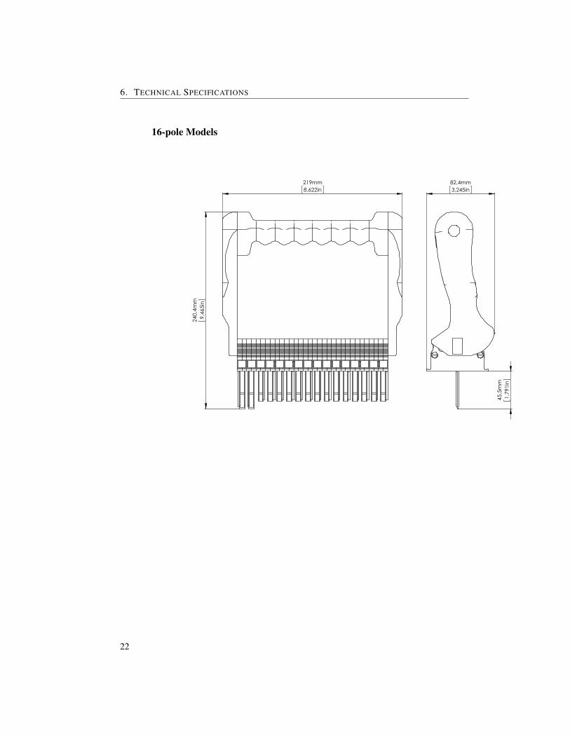
16-pole Models
45,
5mm
1,79
1in
82,4mm3,245in
240
,4m
m9,
465i
n
219mm8,622in
22

Dimensional Drawings FTP
18-pole Models
45,
5mm
1,79
1in
82,4mm3,245in
240
,4m
m9,
465i
n
242mm9,528in
23

6. TECHNICAL SPECIFICATIONS
20-pole Models
45,
5mm
1,79
1in
82,4mm3,245in
240
,4m
m9,
465i
n
265mm10,433in
24

7 Accessories
Cases for FTP Test Plugs
Rugged case for FTP Test Plugs with handle or Test Probes.
Description Order Code
Case for FTP Test Plug CFTP1Case for FTP Test Probes CFTP2
Individual Test Probes
This probes will fit all FTS Test Blocks, regardless of configuration. Keying in theprobes prevents insertion into wrong circuits (i.e., 2-pole current probes can only beinserted into a 2-pole current part of a FTS block).
Current probes include internal shorting bridge.
Description Order Code
Single pole probe (voltages, signals and trips) FTPA01TVSAA2-pole probe (single current and return) FTPA020C2AA
4-pole probe (three currents, common return) FTPA040C4AA
Universal Test Probes Set
Set of individual test probes in a rugged case. Two configurations are available:
“Small” Set
• 3 × 2-pole current probes (for single currents and return)
25

7. ACCESSORIES
• 1 × 4-pole current probes (for three currents and common return)
• 6 × single pole probes (for voltages, trips and signals)
“Large” Set
• 6 × 2-pole current probes (for single currents and return)
• 2 × 4-pole current probes (for three currents and common return)
• 12 × single pole probes (for voltages, trips and signals)
Description Order Code
Universal Test Probe Set “Small” UFTP1Universal Test Probe Set “Large” UFTP2
Current Measurement Probe
This special test probe allows for the connection of a current measurement device or ashunt. The AWG 13 (2.5 mm2) connection cable has a length of 118 inches (3 meters).The test probe is available with c-hook terminals or banana plugs.
The current measurement probe is a special tool that is built for current measurementpurposes. It does NOT automatically short-circuit current transformer circuits uponinsertion into the FTS test block. Instead, current circuits are opened and redirectedvia the attached wires once the probe is entered into the test block. The probe mustalways be correctly connected to a measurement instrument or a shunt before insertioninto the FTS test block, to prevent the creation of an open current transformer circuit.The current measurement probe should be used by properly trained personnel only.
Description Order Code
C-hook connection UTPC1Banana plug connection UTPC2
26

FTS 19” Rack Plates
FTS 19” Rack Plates
SECUCONTROL offers metal plates for installation of FTS test blocks in 19” racksthat come painted in various colors and with various cutouts for FTS test blocks, instandard heights of 2U or 3U. Please contact SECUCONTROL if you require drawingsor special customizations. The picture below shows an ANSI-grey #61 rack plate withthree cutouts for 10-pole FTS test blocks.
F T x 2 U︸︷︷︸height
2 2︸︷︷︸config.
2 2 2 2 2 2︸ ︷︷ ︸cutouts
2 2︸ ︷︷ ︸color
height Rack plates are available in 2U and 3Uconfig. A: standard 19” rack plates, 2mm thick with standard cutouts
B-Z: reserved for special configurationscutout e.g.14xx16 ¿ cutout for one 14-pole (left) and one 16-pole (right)
FTS test blocke.g.14xxxx ¿ cutout for one 14-pole (left) FTS test blocke.g.xxxx18 ¿ cutout for one 18-pole (right) FTS test blocke.g.100810 ¿ cutout for one 10-pole (right), one 8-pole (middle)and one 10-pole (right) FTS test blockmax. modules per rack plate = 30
color These two digits define rack plate colors. Available options canbe found in the table below:
Color Description
AG ANSI-grey #61PG pebble grey RAL 7032LG light grey RAL 7035BK black
For all configurations with 3 cutouts and 30 modules (e.g. 3 x 10-pole cutouts),SECUCONTROL recommends special FTS fitting screws (M5x22). These screws shouldbe mounted on the far left and the far right side of the rack plate, to prevent the tip ofthe screws from touching the mounting frame. Two special screws are included withevery FTS rack plate with 3 cutouts\30 modules. Please use the order codes belowfor reordering.
27

7. ACCESSORIES
Special FTS Fitting Screws
Fitting set to fix the FTS Test Block in the rack plate cutout with 3 cutouts and 30modules. The screw set contains two M5x22 hexagon socket head cap screws (4 mm)
Description Order Code
Special fitting set M5 SCPFT
Covers for 19” FTS Rack Plate Cutouts
Built to cover existing cutouts in rack plates for FTS test blocks, these metal coversare offered for different FTS cutout sizes.
Description Order Code Order Code Order Code Order CodeANSI-grey #61 light grey pebble grey black
8 -pole cover FTBC08AG FTBC08LG FTBC08PG FTBC08BK10-pole cover FTBC10AG FTBC08LG FTBC08PG FTBC08BK12-pole cover FTBC12AG FTBC08LG FTBC08PG FTBC08BK14-pole cover FTBC14AG FTBC08LG FTBC08PG FTBC08BK16-pole cover FTBC16AG FTBC08LG FTBC08PG FTBC08BK18-pole cover FTBC18AG FTBC08LG FTBC08PG FTBC08BK20-pole cover FTBC20AG FTBC08LG FTBC08PG FTBC08BK
28

8 Spare Parts
Dust Covers
# of poles Order Code
8 FTDC0810 FTDC1012 FTDC1214 FTDC1416 FTDC1618 FTDC1820 FTDC20
Fitting Set
Fitting set to fix the FTL Test Block in the panel cutout. The screw set contains twoM5x30 hexagon socket head cap screws (4 mm) and two M5 nuts.
Description Order Code
Fitting set M5 SCSFT
29


9 Ordering Information
Part Numbers for FTS Test Block
F T S A 2 2︸︷︷︸poles
2 2 2︸ ︷︷ ︸config
2 2︸︷︷︸labeling
Part Numbers for FTP Test Plug
F T P P 2 2︸︷︷︸poles
2 2 2︸ ︷︷ ︸config
2 2︸︷︷︸labeling
Available Configurations
A list of available Configurations can be found in the download section of out website.
Should your application require a configuration that is not listed below, please contactSECUCONTROL at any of the addresses listed on the rear cover of this manual, or usethe configurator on our homepage.
31

North AmericaSecuControl Inc.
2873 Duke StreetAlexandria, VA 22314USA
Tel +1 703 838 [email protected]
EuropeSecuControl GmbH
Ascherslebener Str. 3D-06333 HettstedtGermany
Tel +49 3476 550 [email protected]
South AmericaSecuBrasil Ltda
Rod Jose Carlos Daux, 860088050-001 Florianopolis SCBrazil
Tel +55 (48) 3371 [email protected]