Embed Size (px)
Citation preview

1 FToF Design and Overview Report CLAS12 ToF System Review 2009
Requirement and result driven design, construction, quality assurance, man power,
time effort, timeline, and cost estimates
FToF Design and Overview Report
CLAS12 Time-of-Flight System Review 2009
Jefferson Lab, Newport News, VA
Ralf W. Gothe, Evan Phelps, Robert Steiman, and Ye Tian
University of South Carolina

2 FToF Design and Overview Report CLAS12 ToF System Review 2009
Forward Time-of-Flight UpgradeJLab DesignerFTOF Panel 1a
FTOF Panel 1b
Solenoid 5T
CTOF
SVT
Central Detector
DC R1, R2, R3
LTCC
PCAL
EC
HTCC
TORUS
Forward Detector
CLAS12

3 FToF Design and Overview Report CLAS12 ToF System Review 2009
Forward Time-of-Flight UpgradeJLab Designer
2
1

4 FToF Design and Overview Report CLAS12 ToF System Review 2009
Forward Time-of-Flight UpgradeJLab Designer
2
1a&b
Panel 1b

5 FToF Design and Overview Report CLAS12 ToF System Review 2009
Forward Time-of-Flight UpgradeJLab Designer
Panel 1b

6 FToF Design and Overview Report CLAS12 ToF System Review 2009
Forward Time-of-Flight UpgradeJLab Designer
Panel 1b

7 FToF Design and Overview Report CLAS12 ToF System Review 2009
Forward Time-of-Flight Specifcitions
Panel 1b
Hamamatsu R9779: 4.5 in Electron Tubes 9214A: 7.0 in
No light guides!

8 FToF Design and Overview Report CLAS12 ToF System Review 2009
Simulation of Various Light Guides
The plot shows ratio of light that has entered the light guide to the amount that enters the glass envelope of the photomultiplier tube in dependence of the light guide length for two different reflectivities of the wrapping material.
… but penetrating axial magnetic fields
cm
Gordon Mutchler
Reflectivity0.9
0.7

9 FToF Design and Overview Report CLAS12 ToF System Review 2009
Design Requirements
Proton-Pion separation up to 5.3 GeV/c
Kaon-Pion separation up to 2.6 GeV/c
To achieve
and
an improved timing resolution of ~ 80 ps is needed
Proton-Kaon separation up to 4.5 GeV/c

10 FToF Design and Overview Report CLAS12 ToF System Review 2009
The Present Time-of-Flight System
15 cm width (forward angle)22 cm width (large angle)
0 : ElectronicsHas to be optimized!
1 : Scintillator and PMTHas to be optimized!
p : Path-Length VariationHas to be optimized!
Npe: Number of photoelectronsHas to be increased!
Npe increases by 5/2 = (AFTOF6/AFTOF12)(TTOF12/TTOF6)

11 FToF Design and Overview Report CLAS12 ToF System Review 2009
Design Requirements and Results
better than ~ 150 ps for the current FTOF panel
better than ~ 95 ps for the new FTOF panel
With a resolution for the longest scintillators of
and
a combined timing resolution of ~ 80 ps can be accomplishedFTOF12 design counter yields ~ 40 ps (120 cm long)FTOF6 counter yields = 138 ps (213 cm long)
√2/5
BC-404

12 FToF Design and Overview Report CLAS12 ToF System Review 2009
Light Attenuation
BC-404 with 160 cm (Saint Gobain) but 325 cm (measured) BC-408 with 380 cm (Saint Gobain) but 275 cm (measured)
BC-404

13 FToF Design and Overview Report CLAS12 ToF System Review 2009
6 cm 6 cm BC-404/BC-408 Scintillatorstwo sides molded and two diamond-tool finished
Hamamatsu R9779 PMTsactive voltage divider, anode and dynode, inverter, with -shielding, will be glued directly onto the masked scintillator end window
Signal and HV CableRG-174 (BNC) and SCR (SHV) short pigtail, RG-58 (BNC) and RG-59 (SHV) to local sector readout and HV supply
Wrapping aluminized Mylar (scintillator), ligth-tight DuPontTM Tedlar (up to pigtail), black tape (end window mask)
Support Stucturetwo counters will be taped to a support structure as before (CLAS6)
No Detector Calibration System neither Laser nor LED
Current Counter Construction and Design

14 FToF Design and Overview Report CLAS12 ToF System Review 2009
Six Centering Tools
to center PMTs on scintillator end window during 24-hour curing process
Windmill Support Structure
to load horizontally, glue vertically (PMT1), cure, rotate by 180o,
glue vertically (PMT2), cure
Precision Cutter
to cut the Tedlar film
Vacuum Stationto degas the two-component scintillator glue mixture
Black Box
to perform PMT quality assurance in a light-tight environment
Construction Tools
15 FToF Design and Overview Report CLAS12 ToF System Review 2009
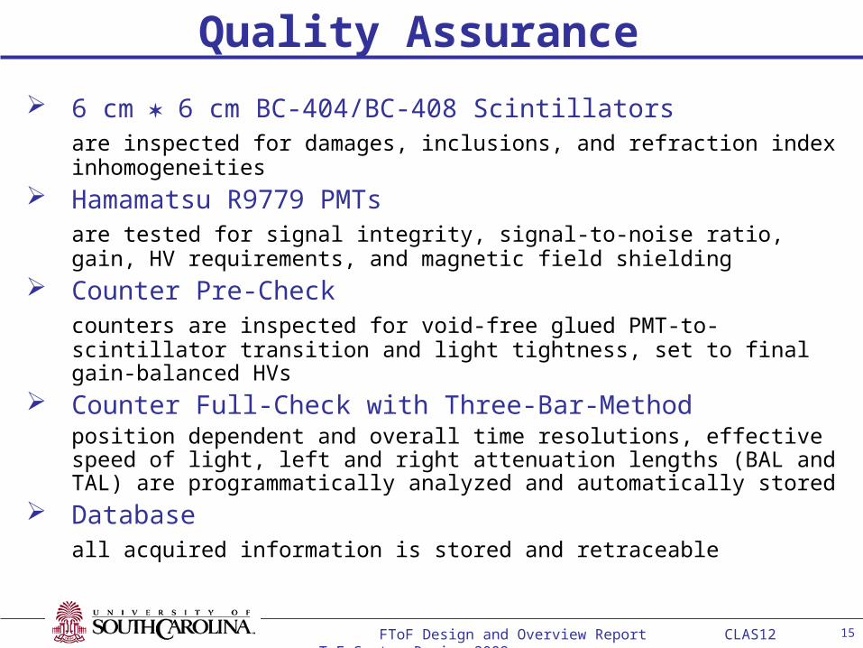
6 cm 6 cm BC-404/BC-408 Scintillatorsare inspected for damages, inclusions, and refraction index inhomogeneities
Hamamatsu R9779 PMTsare tested for signal integrity, signal-to-noise ratio, gain, HV requirements, and magnetic field shielding
Counter Pre-Checkcounters are inspected for void-free glued PMT-to-scintillator transition and light tightness, set to final gain-balanced HVs
Counter Full-Check with Three-Bar-Methodposition dependent and overall time resolutions, effective speed of light, left and right attenuation lengths (BAL and TAL) are programmatically analyzed and automatically stored
Database all acquired information is stored and retraceable
Quality Assurance

16 FToF Design and Overview Report CLAS12 ToF System Review 2009
Assigned USC Manpower 2009/10
FacultyR.W. Gothe (PI)S. Strauch (CoPI)Ch. Djalali, Y. Ilieva, D. Tedeschi
Post DocK. Park (09) G. Fedotov (>10)
Graduate StudentsE. PhelpsL. Graham (MS)H. LuR. Steinman (MS)Y. TianD. Xue
Undergraduate StudentsJ. Giambernadino

17 FToF Design and Overview Report CLAS12 ToF System Review 2009
QA PMT (signal integrity, noise, gain, HV, shielding) 384 mh
C Scintillators (inspect, glue, inspect void-free bond, wrap) 3072 mh
QA Detector (light tightness, gain-balanced HVs, DAQ check) 384 mh
QA TOF, , ceff (10h three-bar method run, comprehensive analysis) 1152 mh
C Pairing (backing structure, storage) 768 mh
C Loading (single layer, individually anchored, foam protected) 288 mh
C Unloading (storage at JLab) 160 mh
C Assembly (assist sector assembly at JLab) 192 mh
QA , HV (sector by sector) 120 mh
Total 6520 mh
USC Time and Effort Estimate
(0.5h*1S*384*2)
(4h*2S*384)
(0.5h*2S*384)
(3h*1S*384)
(2h*2S*384/2)
(0.5h*3S*384/2)
(10’*5S*384/2)
(0.5h*2S*384/2)
(10h*2S*6)
QA PMT (signal integrity, noise, gain, HV, shielding) 384 mh
C Scintillators (inspect, glue, inspect void-free bond, wrap) 3072 mh
QA Detector (light tightness, gain-balanced HVs, DAQ check) 384 mh
QA TOF, , ceff (10h three-bar method run, comprehensive analysis) 1152 mh
C Pairing (backing structure, storage) 768 mh
C Loading (single layer, individually anchored, foam protected) 288 mh
C Unloading (storage at JLab) 160 mh
C Assembly (assist sector assembly at JLab) 192 mh
QA , HV (sector by sector) 120 mh
Total 6520 mh

18 FToF Design and Overview Report CLAS12 ToF System Review 2009
Procurement 1 (PMTs, scintillators, and backing structures) 1/10 – 3/10 FY
Fabrication 1 (PMTs, scintillators, and backing structures) 2/10 – 4/10 FY
Construction 1 (detector assembly at USC) 3/10 – 1/12 FY
QA 1 (concurrent with detector assembly at USC) 3/10 – 1/12 FY
Procurement 2 (PMTs, scintillators, and backing structures) 1/11 – 3/11 FY
Fabrication 2 (PMTs, scintillators, and backing structures) 3/11 – 1/12 FY
Construction 2 (detector assembly at USC) 2/12 – 4/13 FY
QA 2 (concurrent with detector assembly at USC) 2/12 – 4/13 FY
Procurement 3 (cable and sector frames) 2/12 – 3/13 FY
Construction 3 (detector assembly at JLab) 4/13 – 2/14 FY
QA 3 (concurrent with detector assembly at JLab) 4/13 – 2/14 FY
USC Construction Timeline Estimate

19 FToF Design and Overview Report CLAS12 ToF System Review 2009
PMTs (PMT + Inverter) $ 729,300+Tax
Scintillators (Scintillator + Glue) $ 534,800+Tax
Shielding (-metal + active) $ 75,800+Tax
Wrapping (Tedlar + Mylar + Tape + Foam) $ 18,700+Tax
Cable (SHV + BNC + Adapter) $ 136,500+Tax
Tools (Center + Windmill + Cutter + Degas + Black Box) $ 12,800+Tax
Transportation (Packing + Shipping) $ 11,550+Tax
Post Doc (Salary + Fringe) $ 87,150
Students (Man-hours * Wage + Accommodation + Travel) $ 88,700
Total $1,695,300+Tax
Current Cost Estimate
($880+$55)*(384*2+12)
($800/120cm*410cm/2*384)
($100+$100)*384
($11200+$3000+$3000+$1500)
($54524+$47616+$34360)
($1800+$8000+$1500+$1000+$500)
($1050+$5000*2)
($58097/2*3)
(6520h*$12.13+$4612+$5000)
PMTs (PMT + Inverter) $ 729,300+Tax
Scintillators (Scintillator + Glue) $ 534,800+Tax
Shielding (-metal + active) $ 75,800+Tax
Wrapping (Tedlar + Mylar + Tape + Foam) $ 18,700+Tax
Cable (SHV + BNC + Adapter) $ 136,500+Tax
Tools (Center + Windmill + Cutter + Degas + Black Box) $ 12,800+Tax
Transportation (Packing + Shipping) $ 11,550+Tax
Post Doc (Salary + Fringe) $ 87,150
Students (Man-hours * Wage + Accommodation + Travel) $ 88,700
Total $1,695,300+Tax

20 FToF Design and Overview Report CLAS12 ToF System Review 2009
Supplement

21 FToF Design and Overview Report CLAS12 ToF System Review 2009
Acquisitions by 2009
Electronics: NIM (LED, CFD), VME (TDCs), HV (CAEN), Readout (LabView)
Oscilloscopes: DPO 7254 (fast), 1 analog and 2 digital (slow)
PMTs: 2*9214 (Electron Tubes), 2*R9779 (Hamamatsu),
2*XP2020, 2*XP2020UR, 2*XP20Y0, 2*XP20D0 (Photonis)
Voltage Deviders: 2*C638A (Electron Tubes), 2*R9779 (Hamamatsu),
2*VD124KT, 2*VD127KT, 2*XP20Y0, 2*XP20D0 (Photonis)
Scintillators: EJ 204 (50, 100, 250 cm), EJ 200 (50, 100, 250, 400 cm) (ELJEN), BC 404 (20, 50 cm), BC 408 (50, 150, 400 cm) (Saint-Gobain)
Light Guides: 2*BC 802 (UV blind), 2*BC 800 (Saint-Gobain)
Wrapping: Tedlar Film, Aluminized Mylar Film, VM2000, Tape, -Shielding
Others: 2*CLAS ToF Counters, Detector Lab, Assembly Hall, Infrastructure

22 FToF Design and Overview Report CLAS12 ToF System Review 2009
Solenoid (ITK) - Magnetic field distribution
0.00 0.02 0.04 0.06 0.08 0.10 0.120.00
0.02
0.04
0.06
0.08
0.10
0.12
0.0 0.2 0.4 0.6 0.8 1.0 1.20.0
0.2
0.4
0.6
0.8
1.0
1.2
0.0 0.2 0.4 0.6 0.8 1.0 1.20.0
0.2
0.4
0.6
0.8
1.0
1.2
0.0 1.0 2.0 3.0 4.0 5.0 6.00.0
1.0
2.0
3.0
4.0
5.0
6.0
The field maps.
A – General view, the marks are field level (T)B – Field Homogeneity, the marks are non-homogeneity values related to the central field.C – Magnetic flux lines, the marks are magnetic flux confined inside the corresponding surface of revolution (Wb).D – Stray field, the marks are field level (T).
The field homogeneity in a polarized target volume is better than 2.14E-5
A B
C D