Embed Size (px)
Citation preview

1
FTI AIR AODD MODELS FT10P & FT10VAssembly, Installation, & Operation Manual
Record your Model and Serial Number here.
MODEL NUMBER SERIAL NUMBER
P/N 109686 R1

2
EU Declaration of Conformity
FTI Air hereby declares that the following machine(s) fully comply with the applicable health and safety requirements as specified by the EU Directives listed. The complete product complies with the provisions of the EU Directive on machinery safety. This declaration is valid provided that the devices are fully assembled and no modifications are made to these devices.
Type of Device:
Air Operated Double Diaphragm Pumps
Models: FT05P, FT05V, FT05A, FT05S, FT10P, FT10V, FT10A, FT10S FT15P, FT15V, FT15A, FT15S, FT20P, FT20V, FT20A, FT20S
FT30A & FT30S
EU Directives: Machinery Safety (2006/42/EC)
Applied Harmonized Standards:
EN ISO 12100
Manufacturer: FTI Air A Division of Finish Thompson, Inc.
921 Greengarden Road Erie, Pennsylvania 16501-1591 U.S.A
Signed,
President
19 May 2016
Person(s) Authorized to Compile Technical File: FTI Air GmbH
Otto-Hahn-Strasse 16 Maintal, D-63477 DEU Telephone: 49 (0)6181-90878-0

3
Table of Contents
Important Information - READ ME FIRST Export Regulation Notice ........................................................................................................................ 4 Chemical Reaction Disclaimer ................................................................................................................ 4 Safety Precautions ................................................................................................................................. 4-5
Pump Specifications Materials Profiles.................................................................................................................................... 5 Model Number Explanation & Example Part Numbers................................................................................... 6 Dimensional Drawing.............................................................................................................................. 6 Performance Curve................................................................................................................................. 7 Specifications......................................................................................................................................... 7
Installation/Operation Installation Drawing................................................................................................................................ 8 Precautions............................................................................................................................................. 8 Troubleshooting...................................................................................................................................... 9
Maintenance Recommended Tools ............................................................................................................................. 9 Wet End Servicing .................................................................................................................................. 9 Disassembly ................................................................................................................................... 10-11 Reassembly .................................................................................................................................... 12-15 Air End Servicing ................................................................................................................................... 15 Shaft Bushing & O-ring Replacement.............................................................................................. 15-16 Air Valve O-ring Replacement.......................................................................................................... 16-17 Valve & Muffler Gasket Replacement............................................................................................... 17-18 Air Valve Slide, Plate, & Gasket Orientation..................................................................................... 18 Replacement Air Valve Kit Installation.............................................................................................. 19 Exploded View ....................................................................................................................................... 19 Spare Parts List...................................................................................................................................... 19-21
Warranty ....................................................................................................................................................... 22
4
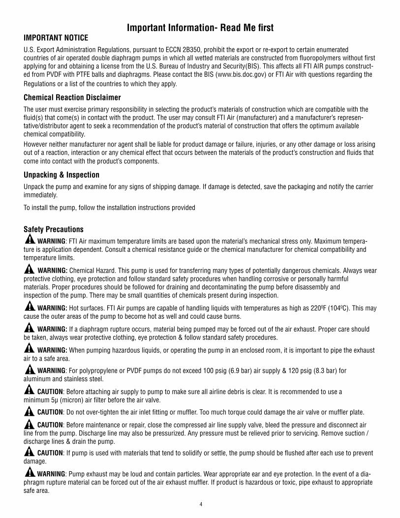
Important Information- Read Me firstIMPORTANT NOTICEU.S. Export Administration Regulations, pursuant to ECCN 2B350, prohibit the export or re-export to certain enumeratedcountries of air operated double diaphragm pumps in which all wetted materials are constructed from fluoropolymers without first applying for and obtaining a license from the U.S. Bureau of Industry and Security(BIS). This affects all FTI AIR pumps construct-ed from PVDF with PTFE balls and diaphragms. Please contact the BIS (www.bis.doc.gov) or FTI Air with questions regarding the Regulations or a list of the countries to which they apply.
Chemical Reaction DisclaimerThe user must exercise primary responsibility in selecting the product’s materials of construction which are compatible with the fluid(s) that come(s) in contact with the product. The user may consult FTI Air (manufacturer) and a manufacturer’s represen-tative/distributor agent to seek a recommendation of the product’s material of construction that offers the optimum available chemical compatibility. However neither manufacturer nor agent shall be liable for product damage or failure, injuries, or any other damage or loss arising out of a reaction, interaction or any chemical effect that occurs between the materials of the product’s construction and fluids that come into contact with the product’s components.
Unpacking & InspectionUnpack the pump and examine for any signs of shipping damage. If damage is detected, save the packaging and notify the carrier immediately.
To install the pump, follow the installation instructions provided
Safety Precautions WARNING: FTI Air maximum temperature limits are based upon the material’s mechanical stress only. Maximum tempera-ture is application dependent. Consult a chemical resistance guide or the chemical manufacturer for chemical compatibility and temperature limits.
WARNING: Chemical Hazard. This pump is used for transferring many types of potentially dangerous chemicals. Always wear protective clothing, eye protection and follow standard safety procedures when handling corrosive or personally harmful materials. Proper procedures should be followed for draining and decontaminating the pump before disassembly and inspection of the pump. There may be small quantities of chemicals present during inspection.
WARNING: Hot surfaces. FTI Air pumps are capable of handling liquids with temperatures as high as 220ºF (104ºC). This may cause the outer areas of the pump to become hot as well and could cause burns.
WARNING: If a diaphragm rupture occurs, material being pumped may be forced out of the air exhaust. Proper care should be taken, always wear protective clothing, eye protection & follow standard safety procedures.
WARNING: When pumping hazardous liquids, or operating the pump in an enclosed room, it is important to pipe the exhaust air to a safe area.
WARNING: For polypropylene or PVDF pumps do not exceed 100 psig (6.9 bar) air supply & 120 psig (8.3 bar) for aluminum and stainless steel.
CAUTION: Before attaching air supply to pump to make sure all airline debris is clear. It is recommended to use a minimum 5µ (micron) air filter before the air valve.
CAUTION: Do not over-tighten the air inlet fitting or muffler. Too much torque could damage the air valve or muffler plate.
CAUTION: Before maintenance or repair, close the compressed air line supply valve, bleed the pressure and disconnect air line from the pump. Discharge line may also be pressurized. Any pressure must be relieved prior to servicing. Remove suction / discharge lines & drain the pump.
CAUTION: If pump is used with materials that tend to solidify or settle, the pump should be flushed after each use to prevent damage.
WARNING: Pump exhaust may be loud and contain particles. Wear appropriate ear and eye protection. In the event of a dia-phragm rupture material can be forced out of the air exhaust muffler. If product is hazardous or toxic, pipe exhaust to appropriate safe area.

5
MaterialChemical
CompositionDescription
Operating Temperature Relative CostMinimum Maximum
Polypropylene Pure Polypropylene Thermoplastic that is resistant to alkali and strong acids.
32°F (0°C)
158°F (70°C) $
PVDF Pure Polyvinylidene Fluoride Strong fluoropolymer with excellent chemical resistance.
10°F (-12°C)
220°F (104°C) $$$
Stainless Steel 316 Stainless Steel Excellent chemical resistance, high tensile and impact strength, abrasion resistant. Limited by other materials used $$
Aluminum ADC 12, LM24, LM25 Moderate chemical resistance with good impact strength and abrasion resistance. Limited by other materials used $
Buna Acrylonitrile-butadiene Rubber
General purpose elastomer.Resistant to oil, water, solvent, and hydraulic fluid.
10°F (-12°C)
190°F (88°C) $
EPDM Ethylene Propylene Diene Rubber
Good resistance to mild acids, detergents, alkalis, ketones, and alcohols.
-40°F (-40°C)
250°F (121°C) $
FKM Fluorocarbon Rubber
Good chemical resistance and high temperature properties. Resistant to most acids, aliphatic, aromatic, and halogenated hydrocarbons, oils, grease, and fuels.
-40°F (-40°C)
350°F (177°C) $$
Neoprene Chloroprene RubberGeneral purpose elastomer with good resistance to moderate chemicals, oils, grease, solvents, and some refrigerants.
0°F (-18°C)
212°F (100°C) $
SantopreneTMFully cured EPDM rubber particles encapsulated in a polypropylene (PP) matrix
Thermoplastic elastomer with good abrasion resis-tance with chemical resistance to a wide range of solvents and chemicals. Injection molded with no fabric layer.
-40°F (-40°C)
225°F (107°C) $
Hytrel® Thermoplastic polyester elastomer
Combines resistance and flexibility of elastomers with the strength of plastics. Resistant to acids, bases, amines, and glycols. Injection molded with no fabric layer.
-20°F (-29°C)
220°F (104°C) $
Polyurethane Polyester Urethane Thermoplastic that exhibits excellent abrasion resistance.Injection molded with no fabric layer.
32°F (0°C)
150°F (66°C) $
PTFE Polytetrafluoroethylene Chemically inert. Resistant to a wide range of chemicals.
40°F (4°C)
225°F (107°C) $$
FEP Fluorinated Ethylene Propylene
Similar to PTFE in composition and chemical resistance. Used to encapsulate FKM o-rings for superior chemical resistance.
40°F (4°C)
225°F (107°C) $$
SantopreneTM is a registered tradename of Exxon Mobil Corp.Hytrel® is a registered tradename of DupontTM
Material Profiles
CAUTION: Use only genuine FTI Air replacement parts to assure compatibility & longest service life.
CAUTION: Check the temperature limits for all wetted components when choosing pump materials. See table below.
EXPLOSION HAZARD! FTI Air pumps with standard materials of construction should not be used with halogenated hydro-carbons. Halogenated hydrocarbon solvents can cause explosion when used with aluminum components in a closed (pressurized) system. FTI Air pumps with standard materials of construction contain aluminum components and will be affected by halogenated hydrocarbon solvents.
1-1-1 Trichloroethane and Methylene Chloride are the most common halogenated hydrocarbons. However, other halogenated hydrocarbon solvents are suspect if used either as part of paint or adhesive formulation, or for clean-up flushing.
For applications that may involve halogenated hydrocarbons, contact FTI Air to discuss the availability of alternative pump materials of construction.

6
Series*FT - Pump EndFW - Wet End
Pump Size*10 - 1”
Wetted Materials*P - Polypropylene V - PVDF
Non-wetted MaterialsP - GFRPP
Air Valve MaterialsA - Aluminum P - GFRPP
Diaphragm Materials*N - Neoprene H - HytrelB - Buna-N U - PolyurethaneE - EPDM 1 - PTFE/NeopreneF - FKM 2 - PTFE/SantopreneR - Santoprene
Check Valve Ball Materials*N - Neoprene F - FKMB - Buna-N R - SantopreneE - EPDM T - PTFE
Check Valve Seat Materials*P - Polypropylene V - PVDF
Check Valve Seat O-Ring Materials*B - Buna-N U - PolyurethaneF - FKM C - FEP/FKMR - Santoprene
ConnectionN - FNPT B - FBSPF - ANSI/DIN/ISO FLANGE (STANDARD)
Porting location1 - End (standard) 2 - Center horizontal3 - Center vertical
SpecialsM1 - Metal muffler
*Required for wet end
Example Pump P/N’s: FT10P-PP-RRPR-N1, FT10P-PA-BBPB-F1, FT10V-PP-1TVC-N2, FT10V-PA-FFVF-B1Example Wet End P/N’s: FW10P-RRPR, FW10P-BBPB, FW10V-1TVC, FW10V-FFVF
Dimensional Drawing
PART # XX XX X - X X - X X X X - X X - X
Non-wetted
Material
Air Valve Material
Diaphragm Material
Check Valve Ball
Check Valve Seat
Seat O-ringSeries Pump
SizeWetted Material Connection Porting
Location
Model Number Explanation & Example Part Numbers
Specials

7
0 25 50 75 100 125 150 175 200 225
0
1
2
3
4
5
6
0
20
40
60
80
100
0 10 20 30 40 50 60
FLOWRATE - LPM
DISC
HARG
E PR
ESSU
RE -
BAR
(MET
ERS)
DISC
HARG
E PR
ESSU
RE -
PSIG
(FEE
T)
FLOWRATE - US GPM
15 (25.5)
AIR CONSUMPTION SCFM (Nm3/hr)
(46)
(92)
(138)
(185)
30 (51.0)
45 (76.5)
60 (102.0)
(231)
(20)
(31)
(41)
(51)
(61)
(10)
FT10P & FT10V Performance
Specifications
Pump Type: Non-Metallic Air Operated Double Diaphragm
Weight: PP - 24.0 lbs (10.9 kgs)PVDF - 34.1 lbs (15.5 kgs)
Air Inlet/Exhaust Size: 1/2” FNPT
Max Air Inlet Pressure: 100 psig (6.9 bar)
Max Material Inlet Pressure: 10 psig (0.7 bar)
Air Consumption @ 100 psi: 52 scfm (88 Nm3/hr)
Noise Level: 73.6 dB(A)
Max Suction Lift: Wet - 28 ft H20 (8.5 m H2O)Dry - 11 ft H20 (3.4 m H2O)
Max Flow Rate: 54 gpm (204 lpm)
Suction/Discharge Size: 1” FNPT/FBSP/FLANGE
Max Particle Size: 0.25” (6.4 mm)
Max Outlet Pressure: 100 psig (6.9 bar)
Displacement Per Stroke: 0.050 gal (0.19 liter)

8
Installation Drawing
Installation and Start upInstall the pump in a vertical position or it may not prime properly. Pump should be located as close to the product being pumped as possible. Suction line length should be as short as possible and limit the number of fittings. Suction line di-ameter should not be reduced smaller than the suction diameter of the pump. When using rigid pipe run short sections of flexible hose or flexible connections between the pump & piping. Secure the pump to a suitable surface.
Air SupplyConnect the pump air inlet to an air supply with sufficient capacity to achieve desired performance. A pressure regulating valve should be installed to insure air supply pressure does not exceed recommended limits.
Air Valve LubricationNo lubrication is required for the air distribution system.
FastenersRe-torque all fasteners before operation. Creep of housing and gasket materials may cause fasteners to loosen. Re-torque all fasteners to the torque specifications listed on the exploded view drawing in this manual.
Air Inlet & PrimingPump will start to operate as soon as the shut-off valve is opened. It is recommended to open the shut-off valve slowly at first. Once the pump primes; the shut-off valve can be opened additionally to increase the pump’s flow. If the pump is oper-ating but not pumping any liquid see the troubleshooting section for tips & suggestions.
Installation / Operation Precautions
9
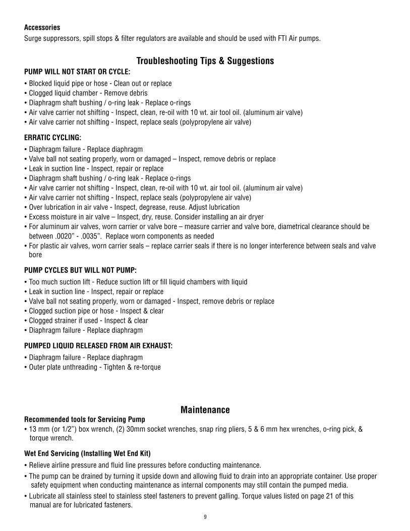
PUMP WILL NOT START OR CYCLE:
• Blocked liquid pipe or hose - Clean out or replace• Clogged liquid chamber - Remove debris• Diaphragm shaft bushing / o-ring leak - Replace o-rings• Air valve carrier not shifting - Inspect, clean, re-oil with 10 wt. air tool oil. (aluminum air valve)• Air valve carrier not shifting - Inspect, replace seals (polypropylene air valve)
ERRATIC CYCLING:
• Diaphragm failure - Replace diaphragm• Valve ball not seating properly, worn or damaged – Inspect, remove debris or replace• Leak in suction line - Inspect, repair or replace• Diaphragm shaft bushing / o-ring leak - Replace o-rings• Air valve carrier not shifting - Inspect, clean, re-oil with 10 wt. air tool oil. (aluminum air valve)• Air valve carrier not shifting - Inspect, replace seals (polypropylene air valve)• Over lubrication in air valve - Inspect, degrease, reuse. Adjust lubrication• Excess moisture in air valve – Inspect, dry, reuse. Consider installing an air dryer• For aluminum air valves, worn carrier or valve bore – measure carrier and valve bore, diametrical clearance should be between .0020” - .0035”. Replace worn components as needed• For plastic air valves, worn carrier seals – replace carrier seals if there is no longer interference between seals and valve bore
PUMP CYCLES BUT WILL NOT PUMP:
• Too much suction lift - Reduce suction lift or fill liquid chambers with liquid• Leak in suction line - Inspect, repair or replace• Valve ball not seating properly, worn or damaged - Inspect, remove debris or replace• Clogged suction pipe or hose - Inspect & clear• Clogged strainer if used - Inspect & clear• Diaphragm failure - Replace diaphragm
PUMPED LIQUID RELEASED FROM AIR EXHAUST:
• Diaphragm failure - Replace diaphragm• Outer plate unthreading - Tighten & re-torque
Troubleshooting Tips & Suggestions
MaintenanceRecommended tools for Servicing Pump• 13 mm (or 1/2”) box wrench, (2) 30mm socket wrenches, snap ring pliers, 5 & 6 mm hex wrenches, o-ring pick, & torque wrench.
Wet End Servicing (Installing Wet End Kit)
• Relieve airline pressure and fluid line pressures before conducting maintenance. • The pump can be drained by turning it upside down and allowing fluid to drain into an appropriate container. Use proper safety equipment when conducting maintenance as internal components may still contain the pumped media.• Lubricate all stainless steel to stainless steel fasteners to prevent galling. Torque values listed on page 21 of this manual are for lubricated fasteners.
AccessoriesSurge suppressors, spill stops & filter regulators are available and should be used with FTI Air pumps.

10
Remove the (8) discharge manifold bolts (item 11) from the discharge manifold (item 32) using a 13mm (or 1/2”) wrench.
Wet End Disassembly
5 To remove the diaphragms (items 20/21), begin by loosening the (2) outer plates (item 19) using (2) 30mm wrenches. Use 6-sided sockets or wrenches to prevent damage to the hex portion of the outer plate.
4 Remove both liquid chambers by removing the (10) bolts (items 17) on each liquid chamber using a 13mm (or ½“) wrench. Inspect and replace diaphragms if needed.
3 Repeat the above steps for the suc-tion manifold (item12). The seat o-rings, valve seats and valve balls (items 13, 14, 15 & 16) are located in the liquid chambers (item 18).
2 The discharge seat o-rings, valve seats, and valve balls (items 13, 14, 15 &16) can now be accessed and replaced if needed.
1
3
2
54
1

11
7 To remove the remaining diaphragm(s) (items 20/21) and plates (items 19 & 22) from the shaft (item 27), place the shaft in a vise fitted with soft jaws. Using a 6-sided 30mm wrench, remove the remaining diaphragm(s) and plates. Soft jaws are required to prevent damaging the shaft. A damaged shaft will result in accelerated o-ring wear. Jaws can be fitted with wood, plastic, rubber, or other soft material to prevent shaft damage.
6 Remove the outer plate, diaphragm(s), and inner plate (items 19, 20/21 & 22) from the side that is loosened. Pull or push the shaft (item 27) and remaining plates and diaphragms out of the center section. If pulling, it may be easier to grip the diaphragm if it is inverted.
After performing required maintenance, the pump can be reassembled. The pump can also be reassembled using the disas-sembly instructions in the reverse order as listed above. For detailed assembly instructions, follow the steps in the Wet End Reassembly section beginning on page 12.
7
6 6

12
Wet End Reassembly
Slide the center hole of one diaphragm (item 21) over the molded in bolt of an outer plate (item 19). The air side of the diaphragm is labeled and should face away from the plastic portion of the outer plate.If the pump is fitted with PTFE diaphragms (item 20), first place a PTFE diaphragm over the molded in bolt of the outer plate (item 19). Then place the backup diaphragm (item 21) on the outer plate. The shape of the PTFE diaphragm and back up dia-phragm should roughly conform to one another. See the exploded view drawing for proper orientation.
Place the inner plate (item 22) over the molded in bolt. Ensure the round recess in the plate faces the diaphragm (item 21).Diaphragms are shown inverted to ease assembly.
Apply a couple drops of a medium strength thread locker, such as Loctite® 246, to the molded in outer plate bolt (item 19). Thread the shaft (item 27) onto the molded in bolt until it is snug to the flat back side of the inner plate (item 22).
32
11
32

13
The shaft (item 27) and shaft o-rings (item 26) should retain the lubricant that was factory applied. If they appear dry, apply a light coat of lithium thick-ened grease. Avoid over lubrication as it can cause decreased performance of the air distribution system.
Push the shaft (item 27) through the center of the shaft bushing (item 24). It is normal for this to be a tight fit, especially if the shaft and shaft o-rings (item 26) are in good condition.
The other diaphragm(s) (items 20/21) and inner/outer plates (items 19 & 22) can be installed onto the opposite end of the shaft (item 27). It may be easier to thread the molded in bolt into the shaft if the dia-phragm(s) is inverted on one or both sides. This can be done by hand.
Tighten and torque the outer plates (item 19). If the pump is fitted with PTFE diaphragms (item 20), it is necessary to restrict their ability to rotate when tightening the outer plates. This can be done by threading the liquid chamber bolts (item 17) through the PTFE diaphragm holes and into the center sec-tion (item 28) on each side. This will ensure that the PTFE diaphragm does not obstruct the bolts ability to thread into the center section when the liquid chambers are installed. Remove these bolts once the outer plates are torqued.
76
54
Note: When installing polytetrafluoroethylene (PTFE) diaphragms, it is important to tighten outer plates simultaneously (turning in opposite directions) to ensure tight fit.
4
7
6
5

14
8 Install the liquid chambers (item 18) by placing one side over the diaphragm. Start all bolts (item 17) before tightening and torqueing. Torque all fasteners in a star pattern. Repeat to install the second liquid chamber. Ensure both chambers are orientated the same and that the inlet and outlet ports are vertical when facing the front of the pump as shown.
9 Flip the pump upside down and drop the suction valve balls (item 16) into the liquid chamber (item 18) ball cages.
10 Place the valve seats (item 15) into the seat bores of the liquid chambers (item 18). The ring gland in the valve seat (item 15) should be fac-ing away from the valve ball. Install the valve seat o-rings (item 13) into the valve seats.
11 Place the manifold o-rings (item 14) into the o-ring gland on the suction manifold (item 12). Place the suction manifold atop the pump and install, tighten, and torque the (8) manifold bolts (item 11).
11
98
10

15
12 Stand the pump upright onto the suction manifold feet (item 12). Place the small valve seat o-rings (item 13) on the flat faces of the liquid chambers (item 18) followed by the valve seats (item 15) on the o-rings, ensuring they are in the gland of the seat. Place the larger o-rings (item 14) into the face glands of the liquid chambers. Place the discharge manifold (item 32) atop the pump, over the components that are stacked on top of the liquid chambers. Install, tighten and torque the (8) manifold bolts.
12
Air End Servicing (Installing Air End Kit)
• Follow steps 1 – 6 in the Wet End Servicing disassembly section to access the shaft bushing (item 24) and o-rings (items 23 & 26), then follow steps below.
1 Remove the shaft bushing retaining ring (item 25) and push the shaft bushing out of the center section.
2 Use the supplied grease packets to lightly grease the OD and ID o-rings (items 23 & 26) that come preinstalled in the new shaft bushing supplied in air end kits.Insert the shaft bushing into the center section (item 28) and reinstall the retaining ring.
21
Shaft, Bushing, & O-ring Replacement
12

16
3 Inspect the shaft (item 27) for damage. It is common for shafts to become grooved during service. Grooving is normally caused by carbonized oil and/or abrasive foreign material getting trapped between the seal and the shaft. Over time, deep grooves can form in the shaft. When that occurs, it is recommended that the shaft be replaced.
3
1 Plastic Air Valve - To replace the valve cap o-ring remove the retaining ring (item 8), then unthread the valve cap (item 6) using a 8mm hex wrench.
1 Aluminum Air Valve - To replace the valve cap o-rings (item 5), remove the (3) button head cap screws (item 7) using a 5mm hex wrench.
1
• After determining if the condition of the shaft is acceptable, follow steps 5 – 12 in the Wet End Servicing – Wet End Reassembly section to rebuild the rest of the pump.
Air Valve O-Ring Replacement
1

17
2 Plastic Air Valve - Remove and replace o-ring (item 5). Install cap (item 6) and tighten until groove for the retaining ring is visible.
2 Aluminum Air Valve - Remove and replace o-ring (item 5). Install cap (item 6), tighten, and torque the valve cap screws (item 7). Repeat for the remaining cap.
22
Valve and Muffler Gasket Replacement
1 Remove the valve body (item 3) by removing the (4) socket head cap screws & washers (items 1 & 2) that attach the valve body to the muffler plate (item 31) with a 6mm hex wrench
2 Pull the valve body and gasket (items 3 & 30) off the front of the center section (item 28) and the muffler plate gasket, muffler plate and muffler (items 29, 31 & 33) off the back.
21

18
3 Place the new gasket (item 30) on the air valve (item 3) and ensure the slots in the gasket align with the slots in the air valve and valve plate (item 10).
Air Valve Slide, Plate & Gasket Orientation: If the valve plate (item 10) and slide valve (item 9) are removed, ensure they are installed in the proper orientation. The flat face of the slide valve sits in the pocket of the valve carrier (item 4) so that the square cut out on the slide valve faces the smooth polished side of the valve plate
3 33
6 Tighten and torque the (4) cap screws into the muffler plate.
5 Place the muffler gasket (item 29) over the (4) cap screws (item 1) on the back side of the center section (item 28) followed by the muffler plate and muffler (items 31 & 33).
4 Insert the (4) cap screws & washers (items 1 & 2) through the valve body and gasket (items 3 & 30) and place onto the center section (item 28). Ensure the slide valve and valve plate (items 9 & 10) are in place and the valve sits flat on the center section.
54 6

19
Replacement Air Valve Kit Installation
1. Remove the valve that is to be replaced by removing the (4) socket head cap screws with a 5mm hex wrench that attaches the valve body to the muffler plate.2. Save the (4) cap screws, (4) lock washers, muffler plate, and muffler. All other valve components can be discarded.3. Remove the packing tape that holds the air valve components in place during shipping.
• Follow steps 3 – 6 in the Valve and Muffler Gaskets section of Air End Servicing above.
Exploded View & Spare Parts List
ITEM DESCRIPTION PART NO. QTY KIT
1 CAP SCREW, SOCKET HD M8X1.25 X 150MM SS 109521 4 -
2 WASHER, LOCK M8 HIGH-COLLAR SS 109518 4 -
3 VALVE BODY SEE AIR VALVE TABLES V1/V2
4 VALVE CARRIER SEE AIR VALVE TABLES V1/V2
5 VALVE CAP O-RING SEE AIR VALVE TABLES A1/A2/V1/V2
6 VALVE CAP SEE AIR VALVE TABLES V1/V2
7 CAP SCREW, SOCKET HD M6X1.0X16MM SS SEE AIR VALVE TABLES V2
8 RETAINING RING, HO-137 SS SEE AIR VALVE TABLES V1
9 SLIDE VALVE 109258 1 V1/V2
10 VALVE PLATE 109262 1 V1/V2
11 CAP SCREW, HEX HD FLNG M8X1.25 X 45MM SS 109508 16 -
12MANIFOLD, SUCTION, POLYPROPYLENE
SEE MANIFOLD TABLES -MANIFOLD, SUCTION, PVDF

20
ITEM DESCRIPTION PART NO. QTY KIT
13
O-RING, VALVE SEAT, BUNA-N 109529
4 W
O-RING, VALVE SEAT, FKM 109322
O-RING, VALVE SEAT, POLYURETHANE 109531
O-RING, VALVE SEAT, SANTOPRENE 109532
O-RING, VALVE SEAT, FEP ENCAPSULATED FKM 109530
14
O-RING, MANIFOLD, BUNA-N 109533
4 W
O-RING, MANIFOLD, FKM J104186
O-RING, MANIFOLD, POLYURETHANE 109534
O-RING, MANIFOLD, SANTOPRENE 109535
O-RING, MANIFOLD, FEP ENCAPSULATED FKM 109327
15VALVE SEAT, POLYPROPYLENE 109292
4 WVALVE SEAT, PVDF 109297
16
VALVE BALL, NEOPRENE (GREEN DOT) 109204
4 W
VALVE BALL, BUNA-N (RED DOT) 109208
VALVE BALL, EPDM (BLUE DOT) 109212
VALVE BALL, FKM (WHITE OR SILVER DOT) 109216
VALVE BALL, SANTOPRENE (RED BALL) 109220
VALVE BALL, PTFE (WHITE BALL) 109200
17 CAP SCREW, M8X1.25 X 45MM 109508 20 -
18LIQUID CHAMBER, POLYPROPYLENE 109103
2 -LIQUID CHAMBER, PVDF 109106
19OUTER PLATE, POLYPROPYLENE 109154
2 -OUTER PLATE, PVDF 109157
20 DIAPHRAGM, PTFE (WHITE) - REQUIRES BACK UP 109183 2 -
21
DIAPHRAGM, NEOPRENE (GREEN DOT) 109187-1
2 W
DIAPHRAGM, BUNA-N (RED DOT) 109187-2
DIAPHRAGM, EPDM (BLUE DOT) 109187-3
DIAPHRAGM, FKM (WHITE OR SILVER DOT) 109187-4
DIAPHRAGM, SANTOPRENE (RED) 109195
DIAPHRAGM, HYTREL (CREAM) 109191
DIAPHRAGM, POLYURETHANE (BEIGE) 109436
22 INNER PLATE 109169 2 -
23 O-RING, BUSHING OD 109416 4 A1/A2
24 SHAFT BUSHING 109179 1 A1/A2
25 RETAINING RING, SH-150 109468 1 A1/A2
26 O-RING, SHAFT 109423 4 A1/A2
27 SHAFT 109174 1 -
28 CENTER SECTION, GF POLYPROPYLENE 109150 1 -
29 GASKET, MUFFLER 109427 1 A1/A2/V1/V2
30 GASKET, AIR VALVE 109266 1 A1/A2/V1/V2
31 MUFFLER PLATE 109270 1 -
32MANIFOLD, DISCHARGE, POLYPROPYLENE
SEE MANIFOLD TABLES -
MANIFOLD, DISCHARGE, PVDF
33 MUFFLER 109561 1 -
21
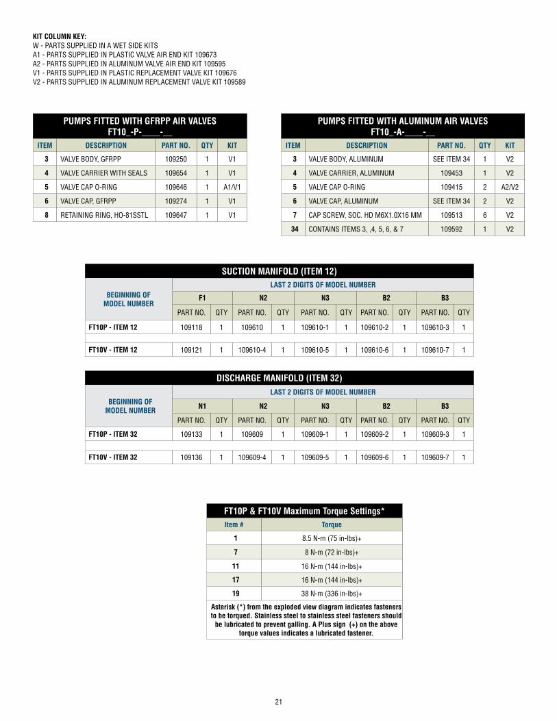
PUMPS FITTED WITH GFRPP AIR VALVESFT10_-P-____-__
ITEM DESCRIPTION PART NO. QTY KIT
3 VALVE BODY, GFRPP 109250 1 V1
4 VALVE CARRIER WITH SEALS 109654 1 V1
5 VALVE CAP O-RING 109646 1 A1/V1
6 VALVE CAP, GFRPP 109274 1 V1
8 RETAINING RING, HO-81SSTL 109647 1 V1
PUMPS FITTED WITH ALUMINUM AIR VALVESFT10_-A-____-__
ITEM DESCRIPTION PART NO. QTY KIT
3 VALVE BODY, ALUMINUM SEE ITEM 34 1 V2
4 VALVE CARRIER, ALUMINUM 109453 1 V2
5 VALVE CAP O-RING 109415 2 A2/V2
6 VALVE CAP, ALUMINUM SEE ITEM 34 2 V2
7 CAP SCREW, SOC. HD M6X1.0X16 MM 109513 6 V2
34 CONTAINS ITEMS 3, ,4, 5, 6, & 7 109592 1 V2
SUCTION MANIFOLD (ITEM 12)
BEGINNING OF MODEL NUMBER
LAST 2 DIGITS OF MODEL NUMBER
F1 N2 N3 B2 B3
PART NO. QTY PART NO. QTY PART NO. QTY PART NO. QTY PART NO. QTY
FT10P - ITEM 12 109118 1 109610 1 109610-1 1 109610-2 1 109610-3 1
FT10V - ITEM 12 109121 1 109610-4 1 109610-5 1 109610-6 1 109610-7 1
DISCHARGE MANIFOLD (ITEM 32)
BEGINNING OF MODEL NUMBER
LAST 2 DIGITS OF MODEL NUMBER
N1 N2 N3 B2 B3
PART NO. QTY PART NO. QTY PART NO. QTY PART NO. QTY PART NO. QTY
FT10P - ITEM 32 109133 1 109609 1 109609-1 1 109609-2 1 109609-3 1
FT10V - ITEM 32 109136 1 109609-4 1 109609-5 1 109609-6 1 109609-7 1
KIT COLUMN KEY:W - PARTS SUPPLIED IN A WET SIDE KITSA1 - PARTS SUPPLIED IN PLASTIC VALVE AIR END KIT 109673A2 - PARTS SUPPLIED IN ALUMINUM VALVE AIR END KIT 109595V1 - PARTS SUPPLIED IN PLASTIC REPLACEMENT VALVE KIT 109676V2 - PARTS SUPPLIED IN ALUMINUM REPLACEMENT VALVE KIT 109589
FT10P & FT10V Maximum Torque Settings*Item # Torque
1 8.5 N-m (75 in-lbs)+
7 8 N-m (72 in-lbs)+
11 16 N-m (144 in-lbs)+
17 16 N-m (144 in-lbs)+
19 38 N-m (336 in-lbs)+
Asterisk (*) from the exploded view diagram indicates fasteners to be torqued. Stainless steel to stainless steel fasteners should
be lubricated to prevent galling. A Plus sign (+) on the above torque values indicates a lubricated fastener.
22
Warranty
FTI Air A Division of Finish Thompson, Inc (manufacturer) warrants this pump product to be free of defects in materials and workmanship for a period of five years from date of purchase by original purchaser. If a warranted defect, which is determined by manufacturer’s inspection, occurs within this period, it will be repaired or replaced at the manufacturer’s option, provided (1) the product is submitted with proof of purchase date and (2) transpor-tation charges are prepaid to the manufacturer.
Liability under this warranty is expressly limited to repairing or replacing the product or parts thereof and is in lieu of any other warranties, either expressed or implied. This warranty does apply only to normal wear of the product or components. This warranty does not apply to products or parts broken due to, in whole or in part, accident, overload, abuse, chemical attack, tampering, or alteration. The warranty does not apply to any other equipment used or purchased in combination with this product. The manufacturer accepts no responsibility for product dam-age or personal injuries sustained when the product is modified in any way. If this warranty does not apply, the purchaser shall bear all cost for labor, material and transportation.
Manufacturer shall not be liable for incidental or consequential damages including, but not limited to process down time, transportation costs, costs associated with replacement or substitution products, labor costs, product installation or removal costs, or loss of profit. In any and all events, manufacturer’s liability shall not exceed the purchase price of the product and/or accessories
FINISH THOMPSON INC. - HEADQUARTERS 921 Greengarden Road | Erie, PA 16501 800.934.9384 | ph 814.455.4478 | fx 814.455.8518email [email protected]
FINISH THOMPSON GMBH - EUROPE CENTEROtto-Hahn-Strasse 16 | Maintal, D-63477 Germany49 (0)6181-90878-0 | fx 49 (0)6181-90878-18email [email protected]