Embed Size (px)
Citation preview
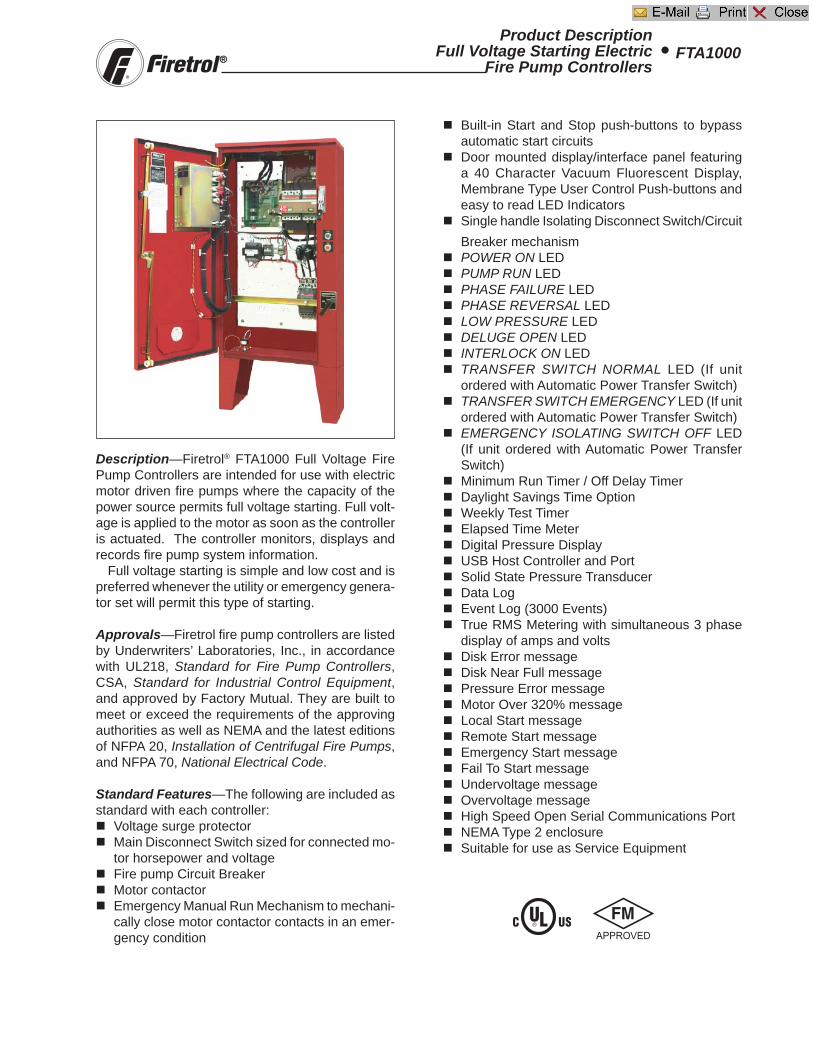
Description—Firetrol® FTA1000 Full Voltage Fire Pump Controllers are intended for use with electric motor driven fi re pumps where the capacity of the power source permits full voltage starting. Full volt-age is applied to the motor as soon as the controller is actuated. The controller monitors, displays and records fi re pump system information.
Full voltage starting is simple and low cost and is preferred whenever the utility or emergency genera-tor set will permit this type of starting.
Approvals—Firetrol fi re pump controllers are listed by Underwriters’ Laboratories, Inc., in accordance with UL218, Standard for Fire Pump Controllers, CSA, Standard for Industrial Control Equipment, and approved by Factory Mutual. They are built to meet or exceed the requirements of the approving authorities as well as NEMA and the latest editions of NFPA 20, Installation of Centrifugal Fire Pumps, and NFPA 70, National Electrical Code.
Standard Features—The following are included as standard with each controller:
Voltage surge protector Main Disconnect Switch sized for connected mo-
tor horsepower and voltage Fire pump Circuit Breaker Motor contactor Emergency Manual Run Mechanism to mechani-
cally close motor contactor contacts in an emer-gency condition
Product DescriptionFull Voltage Starting Electric
Fire Pump ControllersFTA1000•
Built-in Start and Stop push-buttons to bypass automatic start circuits
Door mounted display/interface panel featuring a 40 Character Vacuum Fluorescent Display, Membrane Type User Control Push-buttons and easy to read LED Indicators
Single handle Isolating Disconnect Switch/Circuit Breaker mechanism
POWER ON LED PUMP RUN LED PHASE FAILURE LED PHASE REVERSAL LED LOW PRESSURE LED DELUGE OPEN LED INTERLOCK ON LED TRANSFER SWITCH NORMAL LED (If unit
ordered with Automatic Power Transfer Switch) TRANSFER SWITCH EMERGENCY LED (If unit
ordered with Automatic Power Transfer Switch) EMERGENCY ISOLATING SWITCH OFF LED
(If unit ordered with Automatic Power Transfer Switch)
Minimum Run Timer / Off Delay Timer Daylight Savings Time Option Weekly Test Timer Elapsed Time Meter Digital Pressure Display USB Host Controller and Port Solid State Pressure Transducer Data Log Event Log (3000 Events) True RMS Metering with simultaneous 3 phase
display of amps and volts Disk Error message Disk Near Full message Pressure Error message Motor Over 320% message Local Start message Remote Start message Emergency Start message Fail To Start message Undervoltage message Overvoltage message High Speed Open Serial Communications Port NEMA Type 2 enclosure Suitable for use as Service Equipment
Main Fire Pump ControllerThe main fire pump controller shall be a factory
assembled, wired and tested unit and shall conformto all the requirements of the latest edition of NFPA20, Standard for the Installation of Stationary Pumpsfor Fire Protection and NFPA 70, National ElectricalCode.
The controller shall be listed by Underwriters Labo-ratories, Inc., in accordance with UL218, Standard forFire Pump Controllers, CSA, and Canadian StandardsAssociation CSA-C22.2, Standard for Industrial Con-trol Equipment (cULus), approved by Factory Mutualand approved by the City of New York for fire pumpservice.
Starting MethodThe controller shall be of the combined manual
and automatic type designed for:Full Voltage StartingSolid State Soft StartingWye (Star)-Delta Open Transition StartingWye (Star)-Delta Closed Transition StartingPart Winding StartingPrimary Resistance Reduced Voltage StartingAutotransformer Reduced Voltage Starting
of the fire pump motor having the horsepower, volt-age, phase and frequency rating shown on the plansand drawings. The controller components shall behoused in a NEMA Type 2 (IEC IP11) drip-proof, wallmounted enclosure.
Withstand Ratings (Short Circuit Current Ratings)All controller components shall be front mounted,
wired and front accessible for maintenance. The mini-mum withstand rating of the controllers shall not beless than 100,000 Amps RMS Symmetrical at 200-600 Volts*. If the available system fault current ex-ceeds these ratings, the controllers shall be suppliedwith a withstand rating of 150,000 or 200,000 AmpsRMS Symmetrical, as required.*Note: 100,000 Amp withstand rating not available in
some larger horsepowers. Consult factory fordetails.
Isolation Switch and Circuit BreakerThe controller shall include a motor rated combi-
nation isolating disconnect switch/circuit breaker,mechanically interlocked and operated with a single,externally mounted handle. When moving the handlefrom OFF to ON, the interlocking mechanism shallsequence the isolating disconnect switch ON first, andthen the circuit breaker. When the handle is movedfrom ON to OFF, the interlocking mechanism shallsequence the circuit breaker OFF first, and then theisolating disconnect switch.
The isolating disconnect switch/circuit breakershall be mechanically interlocked so that the enclo-sure door cannot be opened with the handle in theON position except by a hidden tool operated defeatermechanism. The isolating disconnect switch/circuitbreaker shall be capable of being padlocked in theOFF position for installation and maintenance safety,and shall also be capable of being locked in the ON
position without affecting the tripping characteristicsof the circuit breaker. The controller door shall havea locking type handle and three point cam and rollervault type hardware. The circuit breaker trip curveadjustment shall be factory set, tested and sealed forthe full load amps of the connected motor. The circuitbreaker shall be capable of being field tested to verifyactual pick up, locked rotor, and instantaneous trippoints after field installation without disturbing incom-ing line and load conductors.
Operator InterfaceThe fire pump controller shall feature an operator
interface with user keypad. The interface shall moni-tor and display motor operating conditions, includingall alarms, events, and pressure conditions. All alarms,events, and pressure conditions shall be displayedwith a time and date stamp. The display shall be a 2-line, 20-character, vacuum fluorescent, dot matrix typedesigned to allow easy viewing from all angles and inall light conditions. The display and interface shall beNEMA rated for Type 2, 3R, 4, 4X, and 12 protectionand shall be fully accessible without opening the con-troller door. The display and user interface shall uti-lize multiple levels of password protection for systemsecurity. A minimum of 3 password levels shall beprovided. The display shall be capable of being pro-grammed for any language.
Ammeter/VoltmeterThe fire pump controller operator interface shall
be capable of displaying true RMS digital motorvoltage and current measurements for all threephases simultaneously. Displays requiring push-button and selector switches to toggle betweenphases or current and voltage shall not be ac-cepted.
Voltage and current shall be measured by TrueRMS technology to provide the most accuratemeasurement for all sine waves, including non-sinusoidal waveforms. Average responding meterswill not be accepted.
Digital Status/Alarm MessagesThe digital display shall indicate text messages
for the status and alarm conditions of:• Motor On • Sequential Start Time• Minimum Run Time • Local Start / Off Delay Time • Remote Start• Fail to Start • System Battery Low• Under Voltage • Over Voltage• Locked Rotor Trip • Over Frequency• Emergency Start • Motor Over 320%• Drive Not Installed • Motor Overload• Disk Error • Printer Error• Disk Near Full • Pressure Error
The Sequential Start Timer and Minimum Run Timer/Off Delay Timer shall be displayed as numeric valuesreflecting the value of the remaining time.
SpecificationsElectric Fire Pump Controllers • FTA1000
-1900
LED Visual IndicatorsLED indicators, visible with the door closed, shall
indicate:• Power On • Emerg. Isolating Switch Open• Pump Running • Low System Pressure• Alarm • Transfer Switch Normal• Deluge Open • Transfer Switch Emergency• Phase Failure • Phase Reversal• Interlock On
Data LoggingThe digital display shall monitor the system and
log the following data:• Motor Calls/Starts • Elapsed Motor Run Time• Last Trip Currents • Elapsed Power On Time• Last Breaker Trip • Maximum Run Currents• Minimum Voltages • Minimum Run Currents• Maximum Voltages • Last Motor Run Time• Last Phase Failure • Last Start Currents• Last Phase Reversal • Min/Max Frequency• Min/Max Pressure
Event RecordingMemory - The controller shall record all operational
and alarm events to system memory. All events shallbe time and date stamped and include an index num-ber. The system memory shall have the capability ofstoring 3000 events and allow the user access to theevent log via the user interface. The user shall havethe ability to scroll through the stored messages ingroups of 1, 10, or 100. USB Host Controller - The controller shall have abuilt-in USB Host Controller. A USB port capable ofaccepting a USB Flash Memory Disk (aka: flash drive,thumb drive, memory stick, etc..) shall be provided.The controller shall save all operational and alarm eventsto the flash memory on a daily basis. Each savedevent shall be time and date stamped. The total amountof historical data saved shall solely depend on the sizeof the flash disk utilized. The controller shall have thecapability to save settings and values to the flash diskvia the user interface.
Serial Communications - The controller shall fea-ture a RS485 serial communications port for use with2 or 4 wire Modbus RTU communications.
Solid State Pressure TransducerThe controller shall be supplied with a solid state
pressure transducer with a range of 0-300 psi (0-20.7bar) ±1 psi. The solid state pressure switch shall beused for both display of the system pressure and con-trol of the fire pump controller. Systems using analogpressure devices or mercury switches for operationalcontrol will not be accepted.
The START, STOP and SYSTEM PRESSURE shallbe digitally displayed and adjustable through the userinterface. The pressure transducer shall be mountedinside the controller to prevent accidental damage.The pressure transducer shall be directly pipe mountedto a bulkhead pipe coupling without any other support-ing members. Field connections shall be made exter-nally at the controller coupling to prevent distortion ofthe pressure switch element and mechanism.
OperationA digitally set On Delay (Sequential Start) timer
shall be provided as standard. Upon a call to start, theuser interface shall display a message indicating theremaining time value of the On Delay timer.
The controller shall be field programmable formanual stop automatic stop. If set for automatic stop-ping, the controller shall allow the user to select eithera Minimum Run Timer or an Off Delay Timer. Bothtimers shall be programmable through the user inter-face.
SP1000-20 (05-03-07)
Sequence of OperationFull Voltage Fire Pump Controllers FTA1000•
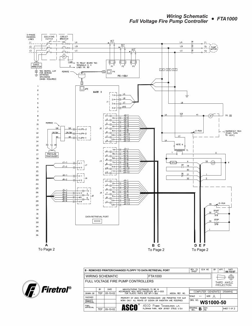
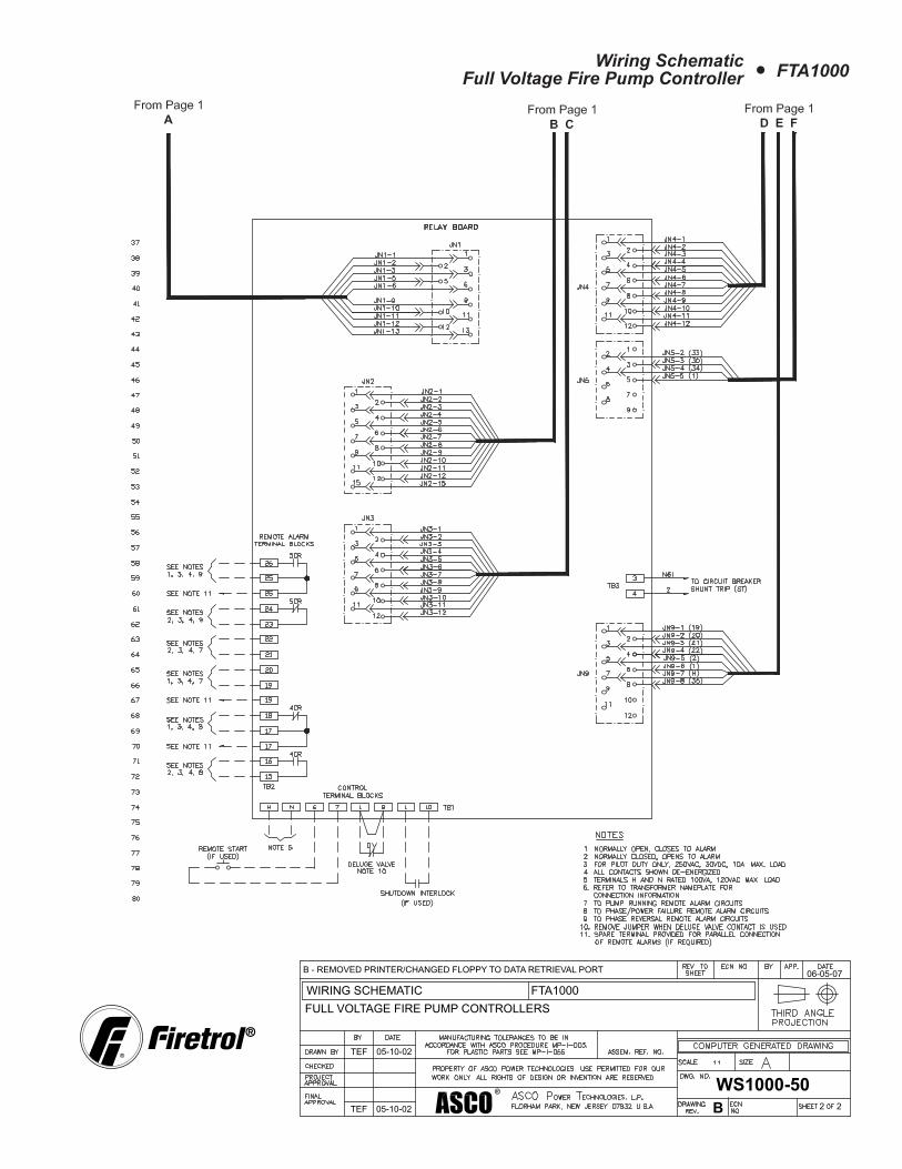
IntroductionThe following information is in reference to Wiring
Schematic, Publication WS1000-50.
Note: Firetrol schematics are drawn showing theequipment in a de-energized state.
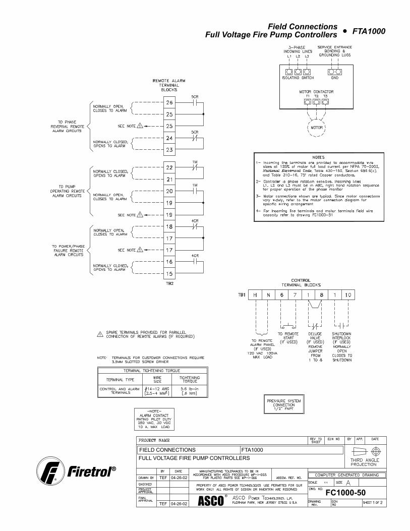
Energizing The Controller1. Close the isolating switch/circuit breaker by movingthe handle to the “ON” position.Note: The unmarked, red, “Interlock” jumper wire, locatedbetween terminals #1 & #10 on the Relay PC board,(TB1), will prevent the MarkII unit from starting the electricmotor automatically. This jumper wire should only beremoved after the pressure settings have been input,and the system pressurized at, or above the Stop setpoint.
2. The factory programmed MarkII unit will begin“initialization”. Upon completion, the display will confirmsystem pressure, the time, date, and “Interlock ON”,which is an alarm condition and will cause the yellowalarm LED to flash. Any other existing alarm conditions(low system pressure, phase reversal, phase failure,deluge open), will also be sequentially and continuouslydisplayed at this time, until each is rectified.
3. With the “interlock” jumper wire still in place, theelectric motor can only be started by depressing theSTART push-button, located on the flange of the controllerenclosure, or by engaging the Emergency RunMechanism. After all alarm conditions have beenrectified, and the system pressurized at or above theStop pressure setting, then the “interlock” jumper maybe removed for the controller’s automatic operation(“standby”). With the “interlock” jumper removed, a dropin system pressure to the MarkII’s set Start point, willstart the electric motor.
4. The deluge valve contacts are only operational if thefactory jumper has been removed and a normally closeddeluge valve contact has been placed between terminals1 and 8 of the Relay PC board, (TB1). The Remote Startis only operational if a normally open, momentarily closedcontact is wired to terminals 6 and 7 of the Relay PCboard, (TB1). If engaged, the Emergency RunMechanism will cause the pump motor to run asdescribed in the Emergency Starting and Stoppingsection.
Automatic Start and Stop1). The controller’s pressure transducer initiates theautomatic start circuits for the pump motor. Whenpressure falls at, or below the MarkII Start setting, relay
1CR is energized. 1CR normally open contact closes,allowing voltage to the motor starter circuits (see sectionPump Motor Starting Sequence for more information)
The minimum run time is a part of the MarkII’s Menu,“Timer Settings” . The minimum run timer’s factory settingis 10 minutes. In this mode, minimum run time beginswhen the pressure falls at or below the “Start” set point,calling for the pump motor to run. When pressure drops,this signals the MarkII to output via the Relay PC board,directly to the 1CR relay coil. The relay’s normally opencontact closes, allowing line voltage to the coil of the1M contactor. The contactor’s 3 normally open contactsclose, allowing 3 phase line voltage to the electric motor,and the motor runs. Simultaneously, the minimum runfunction of the MarkII is activated, maintaining voltageon the 1CR relay coil, and keeping the motor runninguntil the 10 minutes expire. At this time, with pressurerestored at or above the Stop set point, 1CR relay coilwill de-energize, re-opening its normally open contact,de-energizing the 1M contactor coil. It’s 3 normally opencontacts will reopen, causing the motor to de-energizeand stop.
If pressure is restored at, or above the Stop set pointof the MarkII, and even if minimum run time has not yetexpired, the manual STOP push button located on theflange of the controller can be depressed to manuallystop the engine. This also resets the minimum run timefunction of the MarkII.
Manual Start and StopThe pump motor may be manually started by using
either the START push-button mounted on the flange ofthe enclosure or by using a normally open, momentarilyclosed, remote start push-button connected to terminals6 and 7.
When the START push-button is depressed, or aremote start signal is seen through terminals 6 & 7, theMarkII will output through the relay pc board to 1CR relaycoil and the pump motor will be energized and run asdescribed in section “Automatic Start & Stop”. TheMarkII’s minimum run time feature will not be activated.
The pump motor will continue to run until the STOPpush-button is depressed. When the STOP push-buttonis depressed, 1CR relay coil is de-energized, interruptingthe voltage to the 1M contactor coil, which causes themotor to stop.
Deluge Valve OperationTo operate the controller utilizing a deluge valve, the
wire jumper between terminals 1 and 8 must be removedand a normally closed, open to run deluge valve contactwired in its place.
When the deluge valve contact opens, relay 1CR isenergized, closings it’s normally open contact to the1M contactor coil, and the motor runs.
When the deluge valve contact closes, relay 1CR isde-energized, re-opening it’s normally open contact, de-energizing the 1M contactor, and the motor stops.
Shutdown Interlock OperationThe shutdown interlock, if used, is a normally open,
closed to interlock contact wired to terminals 1 and 10.When the interlock contact is closed, relay 1CR
cannot be energized by inputs to the MarkII from thepressure transducer, or the deluge valve. The controllermay be started manually by depressing the manualSTART push button. See the specific starting operationfor more details.
Pump Motor Starting SequenceWhenever relay 1CR is energized, it’s normally open
contact closes, allowing voltage to the coil of the motorstarting contactor. During full voltage starting the followingsequence occurs.
1CR normally open contact closes, energizingcontactor 1M . 1M connects motor terminals T1, T2,and T3 to the power source. This starts the motor in thefull voltage configuration, in which the pump motor draws100% of its normal inrush current and supplies 100% ofits normal starting torque.
Emergency Starting and StoppingThe controller is equipped with an emergency run
mechanism for use in the event of a coil burnout or otherelectrical problem which would prevent normal startingof the pump motor. The mechanism attempts to bothelectrically and mechanically start the pump motor.
When the emergency run mechanism is utilized, ae-run contact is closed, energizing 1M coil. This, ineffect, attempts to electrically start the pump motor.
The emergency run mechanism also manuallycloses the 1M contactor, starting the motor. This willrun the motor as long as the main three phase power isavailable.
If the pump motor is running via the emergency runmechanism, DO NOT release the mechanism to stopthe motor. Place the isolating switch/circuit breakerhandle in the off position, then release the emergencyrun mechanism. Releasing the mechanism while themotor is running could result in damage to the motor orthe motor contactor.Note: The emergency run mechanism is not intendedfor, nor should it be used as a testing device. Its solepurpose is to attempt to start the pump motor in theevent of a failure.
SQ1000-20 (04-12-07)