Embed Size (px)
Citation preview

Installation and Operation Guide
Programmable Electronic Fuel Injection and Ignition System
3
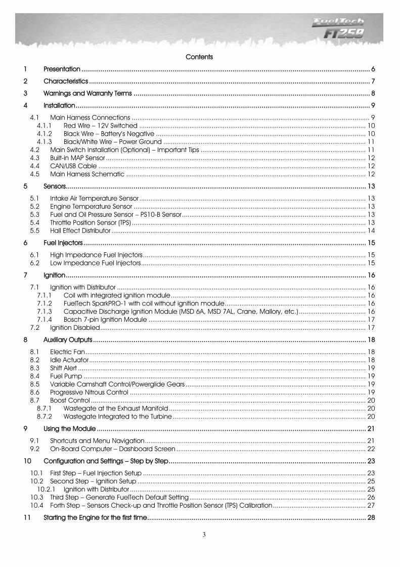
Contents
1 Presentation ..................................................................................................................................................... 6
2 Characteristics ................................................................................................................................................. 7
3 Warnings and Warranty Terms .......................................................................................................................... 8
4 Installation ........................................................................................................................................................ 9
4.1 Main Harness Connections ................................................................................................................................ 9 4.1.1 Red Wire – 12V Switched .......................................................................................................................... 10 4.1.2 Black Wire – Battery’s Negative ................................................................................................................. 10 4.1.3 Black/White Wire – Power Ground ............................................................................................................. 11
4.2 Main Switch Installation (Optional) – Important Tips ......................................................................................... 11 4.3 Built-in MAP Sensor ............................................................................................................................................ 12 4.4 CAN/USB Cable ................................................................................................................................................ 12 4.5 Main Harness Schematic ................................................................................................................................. 12
5 Sensors ........................................................................................................................................................... 13
5.1 Intake Air Temperature Sensor .......................................................................................................................... 13 5.2 Engine Temperature Sensor ............................................................................................................................. 13 5.3 Fuel and Oil Pressure Sensor – PS10-B Sensor ................................................................................................... 13 5.4 Throttle Position Sensor (TPS) .............................................................................................................................. 13 5.5 Hall Effect Distributor ......................................................................................................................................... 14
6 Fuel Injectors .................................................................................................................................................. 15
6.1 High Impedance Fuel Injectors ........................................................................................................................ 15 6.2 Low Impedance Fuel Injectors ......................................................................................................................... 15
7 Ignition ........................................................................................................................................................... 16
7.1 Ignition with Distributor ...................................................................................................................................... 16 7.1.1 Coil with integrated ignition module ......................................................................................................... 16 7.1.2 FuelTech SparkPRO-1 with coil without ignition module ............................................................................ 16 7.1.3 Capacitive Discharge Ignition Module (MSD 6A, MSD 7AL, Crane, Mallory, etc.) .................................... 16 7.1.4 Bosch 7-pin Ignition Module ..................................................................................................................... 17
7.2 Ignition Disabled ............................................................................................................................................... 17
8 Auxiliary Outputs ............................................................................................................................................. 18
8.1 Electric Fan ....................................................................................................................................................... 18 8.2 Idle Actuator ..................................................................................................................................................... 18 8.3 Shift Alert ........................................................................................................................................................... 19 8.4 Fuel Pump ........................................................................................................................................................ 19 8.5 Variable Camshaft Control/Powerglide Gears ................................................................................................. 19 8.6 Progressive Nitrous Control ............................................................................................................................... 19 8.7 Boost Control .................................................................................................................................................... 20
8.7.1 Wastegate at the Exhaust Manifold .......................................................................................................... 20 8.7.2 Wastegate Integrated to the Turbine ........................................................................................................ 20
9 Using the Module ........................................................................................................................................... 21
9.1 Shortcuts and Menu Navigation ....................................................................................................................... 21 9.2 On-Board Computer – Dashboard Screen ...................................................................................................... 22
10 Configuration and Settings – Step by Step ...................................................................................................... 23
10.1 First Step – Fuel Injection Setup ........................................................................................................................ 23 10.2 Second Step – Ignition Setup ........................................................................................................................... 25
10.2.1 Ignition with Distributor ............................................................................................................................... 25 10.3 Third Step – Generate FuelTech Default Setting ............................................................................................... 26 10.4 Forth Step – Sensors Check-up and Throttle Position Sensor (TPS) Calibration .................................................. 27
11 Starting the Engine for the first time ................................................................................................................. 28
4
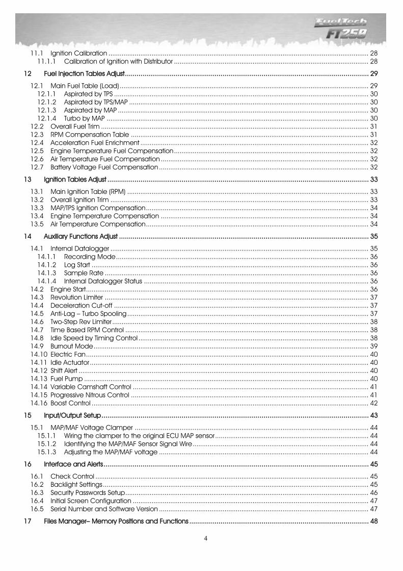
11.1 Ignition Calibration ........................................................................................................................................... 28 11.1.1 Calibration of Ignition with Distributor ........................................................................................................ 28
12 Fuel Injection Tables Adjust ............................................................................................................................. 29
12.1 Main Fuel Table (Load) ..................................................................................................................................... 29 12.1.1 Aspirated by TPS ........................................................................................................................................ 30 12.1.2 Aspirated by TPS/MAP ................................................................................................................................ 30 12.1.3 Aspirated by MAP ...................................................................................................................................... 30 12.1.4 Turbo by MAP ............................................................................................................................................ 30
12.2 Overall Fuel Trim ............................................................................................................................................... 31 12.3 RPM Compensation Table ............................................................................................................................... 31 12.4 Acceleration Fuel Enrichment .......................................................................................................................... 32 12.5 Engine Temperature Fuel Compensation ........................................................................................................ 32 12.6 Air Temperature Fuel Compensation ............................................................................................................... 32 12.7 Battery Voltage Fuel Compensation ................................................................................................................ 32
13 Ignition Tables Adjust ...................................................................................................................................... 33
13.1 Main Ignition Table (RPM) ................................................................................................................................. 33 13.2 Overall Ignition Trim .......................................................................................................................................... 33 13.3 MAP/TPS Ignition Compensation ....................................................................................................................... 34 13.4 Engine Temperature Compensation ............................................................................................................... 34 13.5 Air Temperature Compensation ....................................................................................................................... 34
14 Auxiliary Functions Adjust ................................................................................................................................ 35
14.1 Internal Datalogger .......................................................................................................................................... 35 14.1.1 Recording Mode ....................................................................................................................................... 36 14.1.2 Log Start .................................................................................................................................................... 36 14.1.3 Sample Rate ............................................................................................................................................. 36 14.1.4 Internal Datalogger Status ........................................................................................................................ 36
14.2 Engine Start ....................................................................................................................................................... 36 14.3 Revolution Limiter ............................................................................................................................................. 37 14.4 Deceleration Cut-off ........................................................................................................................................ 37 14.5 Anti-Lag – Turbo Spooling ................................................................................................................................. 37 14.6 Two-Step Rev Limiter ......................................................................................................................................... 38 14.7 Time Based RPM Control .................................................................................................................................. 38 14.8 Idle Speed by Timing Control ........................................................................................................................... 38 14.9 Burnout Mode ................................................................................................................................................... 39 14.10 Electric Fan ....................................................................................................................................................... 40 14.11 Idle Actuator ..................................................................................................................................................... 40 14.12 Shift Alert ........................................................................................................................................................... 40 14.13 Fuel Pump ........................................................................................................................................................ 40 14.14 Variable Camshaft Control .............................................................................................................................. 41 14.15 Progressive Nitrous Control ............................................................................................................................... 41 14.16 Boost Control .................................................................................................................................................... 42
15 Input/Output Setup ......................................................................................................................................... 43
15.1 MAP/MAF Voltage Clamper ............................................................................................................................. 44 15.1.1 Wiring the clamper to the original ECU MAP sensor .................................................................................. 44 15.1.2 Identifying the MAP/MAF Sensor Signal Wire .............................................................................................. 44 15.1.3 Adjusting the MAP/MAF voltage ................................................................................................................ 44
16 Interface and Alerts ........................................................................................................................................ 45
16.1 Check Control .................................................................................................................................................. 45 16.2 Backlight Settings .............................................................................................................................................. 45 16.3 Security Passwords Setup .................................................................................................................................. 46 16.4 Initial Screen Configuration .............................................................................................................................. 47 16.5 Serial Number and Software Version ................................................................................................................ 47
17 Files Manager– Memory Positions and Functions ............................................................................................ 48

5
18 Time-based RPM Control ................................................................................................................................ 49
19 Full Wiring Diagram ........................................................................................................................................ 52

6
1 Presentation
FuelTech FT250 is a fully stand-alone real-time programmable electronic fuel injection system, which allows the adjustment of all injection and ignition maps according to the engine and its characteristics. The programming can be done directly on the module with the use of its buttons, or through the computer software with communication connection via CAN-USB adaptor. With the software, the user has access to 2D and 3D maps that facilitate the visualization and the engine tuning. It can be applied to any type of Otto cycle engines, 2T or 4T engines, motorcycle engines and aquatic crafts with automotive engines, stationary engines, among others. This module features configurable alerts for RPM excess, oil and fuel pressure, air and engine temperature, and others. The alerts can be programmed to cut-off the engine for greater safety. The injection system also has 5 totally independent maps, which allow 5 different configurations for engines and/or cars. Ignition control can be done with the use of a Hall Effect distributor with no need of additional modules, just the ones regarding ignition and driving of low impedance fuel injectors. In order to facilitate the assembly and tuning of 5 and 6-cylinder engines, this module can directly drive up to 12 high impedance fuel injectors. Through the computer software, the user can see all parameters configured and read by real-time fuel injection, as well as save all fuel injection configurations on the computer and transfer them to another module with no information loss.
7
2 Characteristics
Specifications and Inputs Maximum RPM: 16000 Inner MAP Sensor with absolute pressure of 7bar (100psi), (1bar to vacuum and 6bar to positive pressure) 1, 2, 3, 4, 5, 6, 8 and 10-cylinder engines Throttle Position Sensor (TPS) can be calibrated to any linear sensor Engine and Intake Air Temperature Sensor Oil and Fuel Pressure Sensor 4 Configurable Auxiliary Outputs Ignition Control Hall effect distributor Drives up to 12 fuel injectors in 2 independent sets. More fuel injectors can be controlled when using the Peak and
Hold module
Functions Main map options: Aspirated by TPS, Aspirated by TPS/MAP, Aspirated by MAP, Turbo by MAP Idle speed control adjustment options: by MAP or TPS Real-time programmable on the equipment or with the PC software Fuel injection and ignition map based on RPM Main fuel table overall trim function Acceleration fuel enrichment by MAP or by TPS Compensation of ignition timing based on turbo vacuum and pressure or throttle position sensor (TPS) Compensation of fuel injection and ignition based on engine and air temperature (11 temperature points) Compensation of fuel injection based on battery voltage (with 1.0V interval) Rev limiter based on fuel cut-off, ignition cut-off, or ignition and fuel cut-off Deceleration fuel cut-off Two-step with anti-lag Burnout Mode Electronic control of the electric fan based on temperature Idle air valve control based on engine temperature, minimum RPM and after-launch Adjustable engine starting injection based on engine temperature (3 parameters) Electric fuel pump control Variable Valve Timing Control System (VTEC) Progressive nitrous control with mixture enrichment and timing retard Boost pressure control based on RPM, with mixture enrichment Oil and fuel pressure sensors User and tuner protection passwords Fuel injector dead time adjustment for injector’s real duty cycle calculation Visual and sound shift alert and output for external shift light switching Check control with warning and engine cut-off based on exceeded pressure, exceeded RPM, engine
temperature, saturated injectors, oil pressure, fuel pressure and fuel differential pressure LCD Display backlight adjustment 5 memories to save different adjustment from map sets
On-Board Computer – Dashboard Screen Fuel injectors’ current and maximum injection time (in milliseconds, ms) from each set Ignition timing (in oBTDC), injection time (in ms), RPM and TPS (in %) Ignition timing: minimum and maximum values reached (in oBTDC) MAP pressure: current and maximum value reached (in psi) Throttle Position Sensor (TPS): current and maximum value reached (in %) RPM: current and maximum value reached Current Intake Air Temperature: lowest and highest temperatures reached (in oC) Engine Temperature: current and highest temperatures reached (in oC) Oil Pressure: current, lowest and highest (in psi) Fuel Pressure: current, lowest and highest (in psi) Percentage of boost used, ignition timing and boost pressure Percentage of nitro used, ignition timing and enrichment percentage Battery Voltage
Dimensions: 140mm x 80mm x 30mm
8
3 Warnings and Warranty Terms
The use of this equipment implies the total accordance with the terms described in this manual and exempts the manufacturer from any responsibility regarding to product misuse.
Read all the information in this manual before starting the product installation.
This product must be installed and tuned by specialized auto shops and/or personnel with experience on engine preparation and tuning.
Before starting any electric installation, disconnect the battery.
The inobservance of any of the warnings or precautions described in this manual might cause engine
damage and lead to the invalidation of this product warranty. The improper adjustment of the product might cause engine damage.
This product does not have a certification for the use on aircrafts or any flying devices, as it has not been designed for such use purpose.
In some countries where an annual inspection of vehicles is enforced, no modification in the original fuel
injection system is permitted. Be informed about local laws and regulations prior to the product installation.
Important warnings for the proper installation of this product:
Always cut the unused parts of cables off – NEVER roll up the excess as it becomes an interference capturing antenna and it can result on equipment malfunction.
The black wire in the cable MUST be connected directly to the battery’s negative terminal, as well as each one of the sensors’ ground wires.
The black/white wire MUST be connected directly to the engine block or head. By doing so, many interference problems are avoided.
Limited Warranty
This product warranty is limited to one year from the purchase date and covers defects from manufacturing
origin only.
Defects and damages caused by the misuse of this product are not covered by the warranty. This module has a serial number that is linked to the purchase invoice and to the warranty. In case of product exchange, contact FuelTech.
The violation of the seal results in the invalidation of the Product Warranty and the loss of any access to new upgrade releases.
Manual version 1.1 – September/2013
9
4 Installation
For FT250 installation, the electric cable must be disconnected from the module and the vehicle’s battery. It is very important that the cable length is the shortest possible and that exceeding unused parts of wires are cut off. Never roll up the excess of any wire in the cable; by doing so, interference problems, which are very usual with any electronic device, are avoided. Choose an appropriate location to affix the module inside the car, and avoid passing the cable wires close to the ignition wires and cables, ignition coils and other sources of electric noise. Avoid placing the injection module at the engine compartment or where it may be exposed to liquids and heat. DON’T EVER, under any circumstance, install the injection module near the ignition module in order to avoid the risk of interferences. The black wire in the cable is the signal ground wire, and must be connected to the battery’s negative terminal. The black/white wire is the power ground wire, and must be connected to the vehicle’s chassis. The electric cable must be protected from contact with sharp parts on the vehicle’s body that might damage the wires and cause short circuit. Be particularly attentive to wires passing through holes, and use rubber protectors or any other kind of protective material to prevent any damage to the wires. At the engine compartment, pass the wires through places where they will not be subject to excessive heat and will not obstruct any mobile parts in the engine. Always, when possible, use plastic insulation on cables.
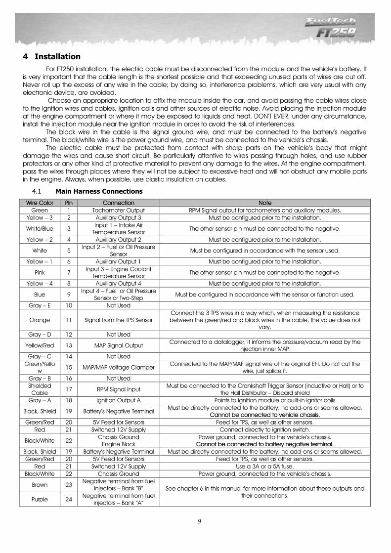
Main Harness Connections 4.1
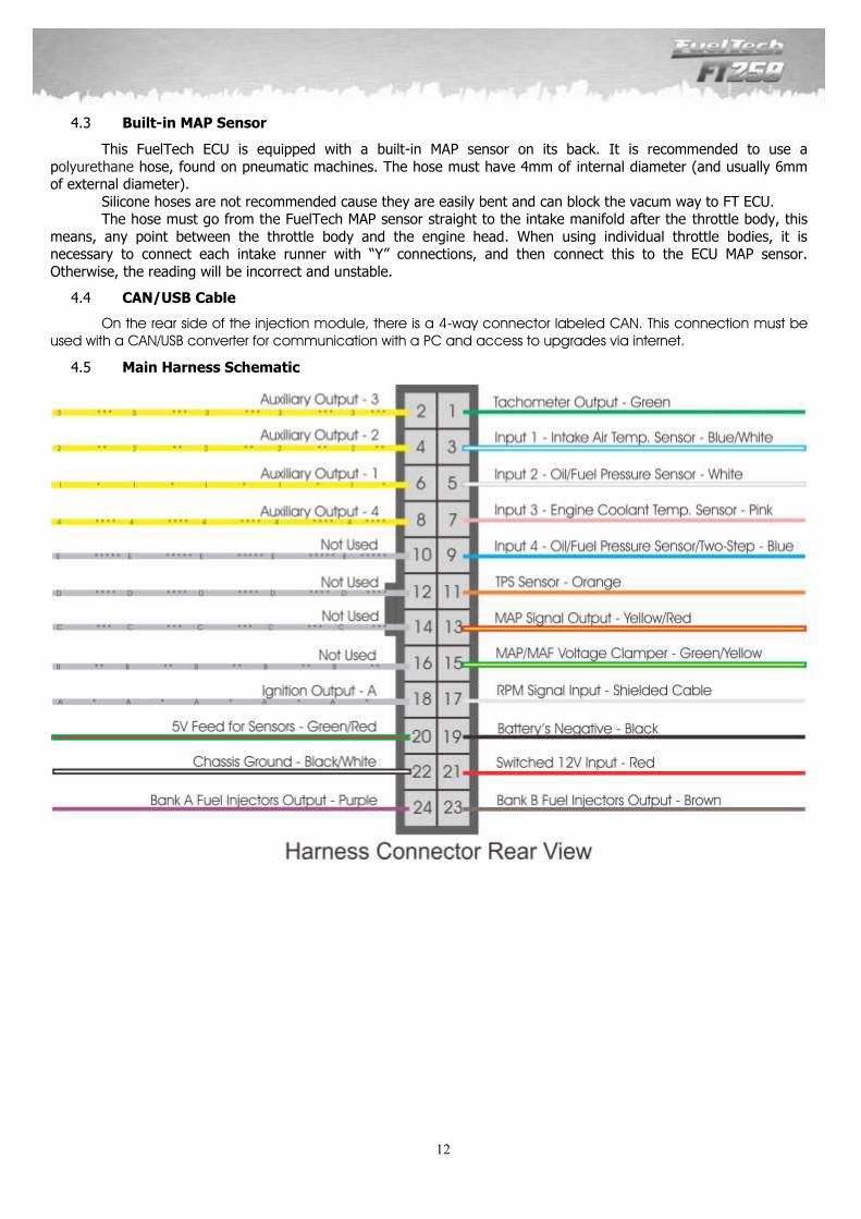
Wire Color Pin Connection Note
Green 1 Tachomoter Output RPM Signal output for tachometers and auxiliary modules.
Yellow – 3 2 Auxiliary Output 3 Must be configured prior to the installation.
White/Blue 3 Input 1 – Intake Air
Temperature Sensor The other sensor pin must be connected to the negative.
Yellow – 2 4 Auxiliary Output 2 Must be configured prior to the installation.
White 5 Input 2 – Fuel or Oil Pressure
Sensor Must be configured in accordance with the sensor used.
Yellow – 1 6 Auxiliary Output 1 Must be configured prior to the installation.
Pink 7 Input 3 – Engine Coolant
Temperature Sensor The other sensor pin must be connected to the negative.
Yellow – 4 8 Auxiliary Output 4 Must be configured prior to the installation.
Blue 9 Input 4 – Fuel or Oil Pressure
Sensor or Two-Step Must be configured in accordance with the sensor or function used.
Gray – E 10 Not Used
Orange 11 Signal from the TPS Sensor Connect the 3 TPS wires in a way which, when measuring the resistance between the green/red and black wires in the cable, the value does not
vary.
Gray – D 12 Not Used
Yellow/Red 13 MAP Signal Output Connected to a datalogger, it informs the pressure/vacuum read by the
injection inner MAP.
Gray – C 14 Not Used
Green/Yellow
15 MAP/MAF Voltage Clamper Connected to the MAP/MAF signal wire of the original EFI. Do not cut the
wire, just splice it.
Gray – B 16 Not Used
Shielded Cable
17 RPM Signal Input Must be connected to the Crankshaft Trigger Sensor (inductive or Hall) or to
the Hall Distributor – Discard shield
Gray – A 18 Ignition Output A Points to ignition module or built-in ignitor coils
Black, Shield 19 Battery’s Negative Terminal Must be directly connected to the battery; no add-ons or seams allowed.
Cannot be connected to vehicle chassis.
Green/Red 20 5V Feed for Sensors Feed for TPS, as well as other sensors.
Red 21 Switched 12V Supply Connect directly to ignition switch.
Black/White 22 Chassis Ground
Engine Block Power ground, connected to the vehicle’s chassis.
Cannot be connected to battery negative terminal.
Black, Shield 19 Battery’s Negative Terminal Must be directly connected to the battery; no add-ons or seams allowed.
Green/Red 20 5V Feed for Sensors Feed for TPS, as well as other sensors.
Red 21 Switched 12V Supply Use a 3A or a 5A fuse.
Black/White 22 Chassis Ground Power ground, connected to the vehicle’s chassis.
Brown 23 Negative terminal from fuel
injectors – Bank “B” See chapter 6 in this manual for more information about these outputs and their connections.
Purple 24 Negative terminal from fuel
injectors – Bank “A”
10
Red Wire – 12V Switched 4.1.1
Being the 12V input to FuelTech ECU, this wire must be connected to a 12V straight from the ignition switch, no relay needed, just a 5A fuse. It cannot be split with a positive to coils or to fuel injectors.
12V for fuel injectors: use a 14 AWG connected to a 40A relay. For up to 4 injectors, a 20A fuse is recommended. For up to 8 injectors, a 30A fuse is recommended. Low impedance injectors (below 10 ohms), when used without a Peak and Hold driver, require a 3,3ohms or 2,7ohms ballast resistor (20W ou 25W), connected in series with each fuel injector to avoid damage to the ECU. But be aware that when using low impedance injectors with ballast resistor, each ECU injector output can drive only two injectors.
12V for hall effect distributor and sensors: use a 24 AWG wire straight from the ignition switch. It can be Split with the ECU 12V. No relay needed. Do not split this wire with a 12V that feeds fuel injectors or coils. Exemples: hall effect sensors, pressure sensors, etc.
12V for coils and fuel pump: use a wire with at least 14 AWG connected to a 40A relay. Each relay can feed up to 2 fuel pumps or 5 coils. A 30A fuse is recommended. When using individual coils (COP), it is recommended a 70A or 80A relay.
NEVER split the 12V that feed injectors, coils or ther accessories, cause, after shutting the engine off, there’s a risk of reverse current that may damage a sensor.
Black Wire – Battery’s Negative 4.1.2
This wire is responsible for signal ground to the ECU so, it must be connected straight to the battery’s negative terminal, with no seams. Under no hypothesis this wire can be connected to the vehicle chassis or split with the ECU black/white wire (power ground). This will cause electromagnetic interference and other problems hard to diagnose and to solve.
The black wire must have permanent contact with the battery’s negative terminal, never being connected to switches, car alarms or others. To turn a FuelTech ECU off, the red wire should be switched on and off.
Negative for sensors (TPS, air temp., pressure, rpm, distributor, etc.): It is vital to use sensors ground straight to
the battery’s negative terminal. Connecting them to chassis may cause electromagnetic interference,
wrong readings or even damage to the sensors.
To attach the negative wires to the battery terminal use ring terminals and avoid soldering them. A well
crimped terminal has better resistance than a soldered one. Besides that, solder makes the seam stiffer, and
less resistant to vibration, typically found on combustion engines.
Use a crimping tool and insulate the wire with insulating tape or heatshrink tubing.
11
Black/White Wire – Power Ground 4.1.3
This is the FuelTech ECU power ground wire. It must be connected to the vehicle chassis, with the same shield that goes from the chassis to the battery’s negative terminal. Under no circumstance this wire can be connected straight to the battery’s negative terminal or in the same point that the ECU black wire. This will cause electromagnetic interference and other problems hard to diagnose and to solve.
The black/white wire must have permanent contact with the vehicle chassis, never being connected to switches, car alarms or others. To turn a FuelTech ECU off, the red wire should be switched on and off.
Power ground to ignition modules (SparkPRO, etc.), Peak and Hold drivers, relays and other accessories, must
be connected to the same point, with the battery’s shield on the chassis.
An important point is that the battery’s shield must be in good shape. It is strongly recommended to replace
it in case of heavy wearing.
A good test to check if the power grounds are with good connection is, using a multimeter, to measure the
resistance between the battery’s negative terminal and the chassis ground. Connect the red probe on the
chassis point that the shield is connected and the black probe on the battery’s negative. With the multimeter
on the 200ohms range, the resistance measured must be below 1 ohm. Remember to touch both probes
to check its resistance. This reading must be subtracted from the first reading to found the correct value.
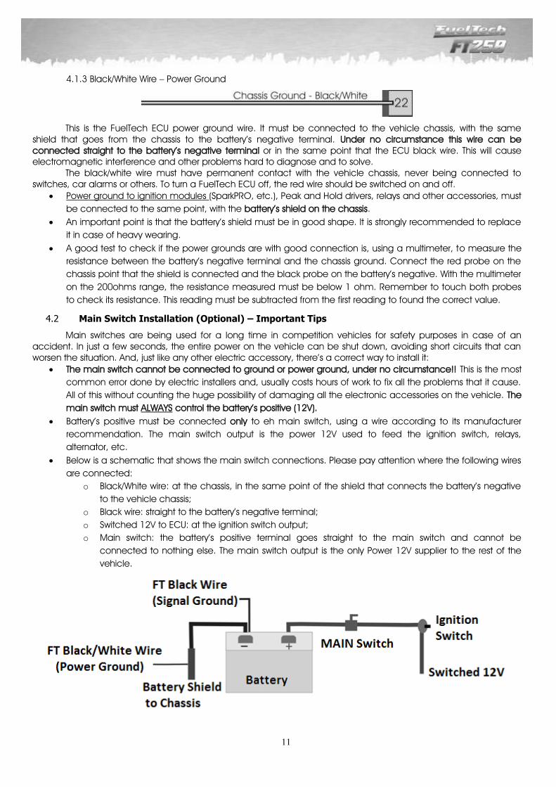
Main Switch Installation (Optional) – Important Tips 4.2
Main switches are being used for a long time in competition vehicles for safety purposes in case of an accident. In just a few seconds, the entire power on the vehicle can be shut down, avoiding short circuits that can worsen the situation. And, just like any other electric accessory, there’s a correct way to install it:
The main switch cannot be connected to ground or power ground, under no circumstance!! This is the most
common error done by electric installers and, usually costs hours of work to fix all the problems that it cause.
All of this without counting the huge possibility of damaging all the electronic accessories on the vehicle. The
main switch must ALWAYS control the battery’s positive (12V).
Battery’s positive must be connected only to eh main switch, using a wire according to its manufacturer
recommendation. The main switch output is the power 12V used to feed the ignition switch, relays,
alternator, etc.
Below is a schematic that shows the main switch connections. Please pay attention where the following wires
are connected:
o Black/White wire: at the chassis, in the same point of the shield that connects the battery’s negative
to the vehicle chassis;
o Black wire: straight to the battery’s negative terminal;
o Switched 12V to ECU: at the ignition switch output;
o Main switch: the battery’s positive terminal goes straight to the main switch and cannot be
connected to nothing else. The main switch output is the only Power 12V supplier to the rest of the
vehicle.
12
Built-in MAP Sensor 4.3
This FuelTech ECU is equipped with a built-in MAP sensor on its back. It is recommended to use a
polyurethane hose, found on pneumatic machines. The hose must have 4mm of internal diameter (and usually 6mm of external diameter).
Silicone hoses are not recommended cause they are easily bent and can block the vacum way to FT ECU. The hose must go from the FuelTech MAP sensor straight to the intake manifold after the throttle body, this
means, any point between the throttle body and the engine head. When using individual throttle bodies, it is necessary to connect each intake runner with “Y” connections, and then connect this to the ECU MAP sensor.
Otherwise, the reading will be incorrect and unstable.
CAN/USB Cable 4.4
On the rear side of the injection module, there is a 4-way connector labeled CAN. This connection must be used with a CAN/USB converter for communication with a PC and access to upgrades via internet.
Main Harness Schematic 4.5

13
5 Sensors
Intake Air Temperature Sensor 5.1
The use of this sensor is optional, but when installed, it is automatically detected by the injection system. It allows to monitor the intake air temperature in real-time through the dashboard screen, verify the highest temperatures reached and compensate the mixture automatically based on air temperature. With this sensor, it is possible to automatically compensate climate variations, from alterations in air temperature between daytime and night time, up to changes between seasons throughout the year. Any temperature difference requires a fine-tuned compensation in the mixture in order to keep the desired performance and efficiency. The sensor that must be used is the Delphi / NTK (3.3kΩ at 20oC) standard, similar to the ones used by the Fiat lines, which has a metal structure and can be fixed to a nut welded to the intake manifold or at the pressurization.
Engine Temperature Sensor 5.2
The use of this sensor is key for the proper operation of the engine in all temperature ranges, especially when running cold, shortly after starting up for launch. In cars with water cooling system, this sensor must be placed near to the engine cylinder head, preferably at an original part, in an originally injected engine. In cars with air cooling system, this sensor can be placed in the engine oil, as the fluid represents the temperature in which the engine works.
The Delphi / NTK (3.3kΩ at 20oC) standard model must be used.
Fuel and Oil Pressure Sensor – PS10-B Sensor 5.3
The use of this sensor is optional, but when installed, it is automatically detected by the ECU. It allows to monitor fuel or oil pressure in real-time through the dashboard screen. With the Check Control function, it is possible to program pressure warnings. When installing this sensor, the ECU must be configured at the “Input/Output Setup” menu.
This pressure sensor performs general pressure readings (fuel, oil, etc.). It can be purchased online (www.fueltechusa.com) or from FuelTech dealers (check the website to locate the dealer nearest to you).
FuelTech PS-10B Sensor Specifications: Output Signal: 1 to 5V Electric Connections:
Pin 1: Battery’s Negative Pin 2: Output Signal 1 to 5V Pin 3: Switched 12V
Connection: 1/8” NPT Pressure Range: 0 to 145psi Feed Voltage: 12V Body structure in stainless steel and IP67 Accuracy (including nonlinearity, hysteresis, and repeatability): +/- 0.5% at maximum readings
range. Electric Connector: 3-way AMP Superseal (FuelTech Code 1014)
Throttle Position Sensor (TPS) 5.4
The Throttle Position Sensor (TPS) is a potentiometer placed on the throttle body in order to inform its angular position. The TPS is the main sensor in the injection system when used in an aspirated engine without steady vacuum. When the engine is an aspirated by MAP, or Turbo by MAP, the TPS can be used to regulate the idle, the acceleration enrichment and the deceleration fuel cut-off. In special cases, the engine can run without this sensor, but all the functions above mentioned will be performed by the MAP (with prejudice to fine-tune adjustment details). All throttle bodies come with a TPS, and it is recommended that the original TPS is used, as its fixation and flow are in perfect fit to the part it came with. In any event, FuelTech products are compatible with any TPS sensor, as they have calibration functions.
Fiat Nº 75.479.76, MTE-5053 ou IG901
Fiat Nº 026.906.161.12, MTE-4053 ou IG802
Electrical Connections – Sensor View
14
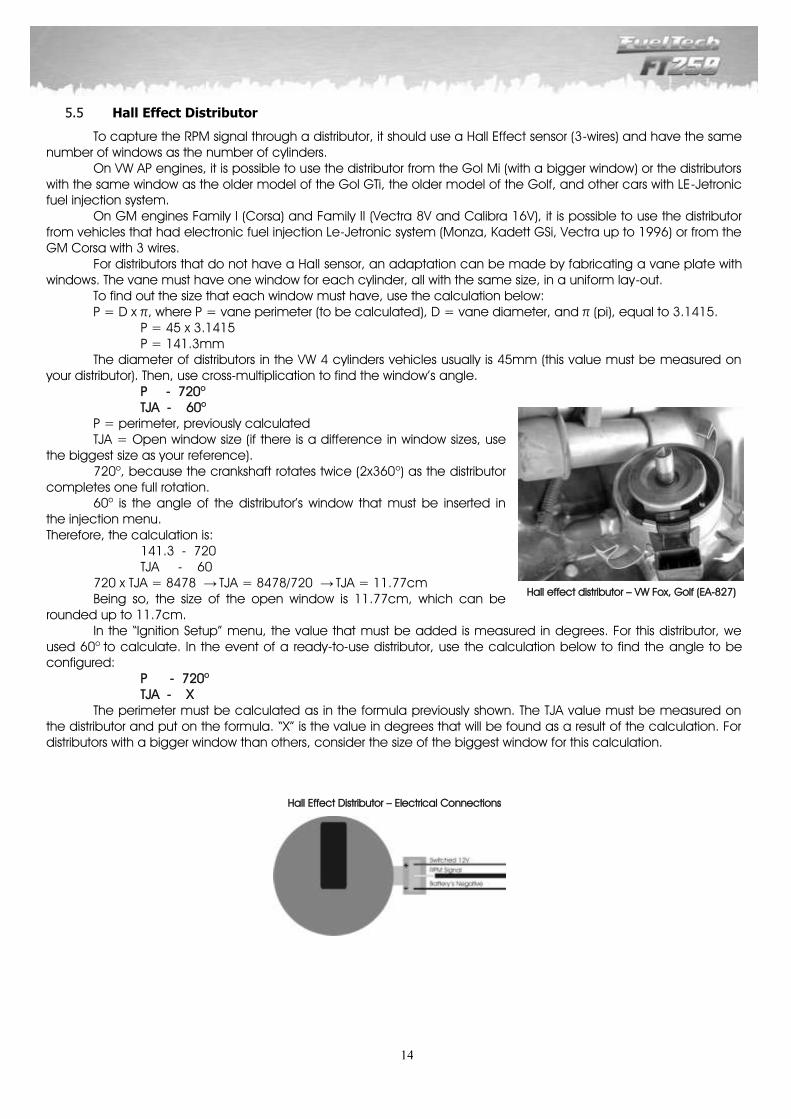
Hall Effect Distributor 5.5
To capture the RPM signal through a distributor, it should use a Hall Effect sensor (3-wires) and have the same number of windows as the number of cylinders. On VW AP engines, it is possible to use the distributor from the Gol Mi (with a bigger window) or the distributors with the same window as the older model of the Gol GTi, the older model of the Golf, and other cars with LE-Jetronic fuel injection system. On GM engines Family I (Corsa) and Family II (Vectra 8V and Calibra 16V), it is possible to use the distributor from vehicles that had electronic fuel injection Le-Jetronic system (Monza, Kadett GSi, Vectra up to 1996) or from the GM Corsa with 3 wires. For distributors that do not have a Hall sensor, an adaptation can be made by fabricating a vane plate with windows. The vane must have one window for each cylinder, all with the same size, in a uniform lay-out. To find out the size that each window must have, use the calculation below: P = D x π, where P = vane perimeter (to be calculated), D = vane diameter, and π (pi), equal to 3.1415. P = 45 x 3.1415 P = 141.3mm The diameter of distributors in the VW 4 cylinders vehicles usually is 45mm (this value must be measured on your distributor). Then, use cross-multiplication to find the window’s angle. P - 720o
TJA - 60o P = perimeter, previously calculated TJA = Open window size (if there is a difference in window sizes, use the biggest size as your reference). 720o, because the crankshaft rotates twice (2x360o) as the distributor completes one full rotation. 60o is the angle of the distributor’s window that must be inserted in the injection menu. Therefore, the calculation is: 141.3 - 720 TJA - 60 720 x TJA = 8478 → TJA = 8478/720 → TJA = 11.77cm Being so, the size of the open window is 11.77cm, which can be rounded up to 11.7cm. In the “Ignition Setup” menu, the value that must be added is measured in degrees. For this distributor, we used 60o to calculate. In the event of a ready-to-use distributor, use the calculation below to find the angle to be configured: P - 720o
TJA - X The perimeter must be calculated as in the formula previously shown. The TJA value must be measured on the distributor and put on the formula. “X” is the value in degrees that will be found as a result of the calculation. For distributors with a bigger window than others, consider the size of the biggest window for this calculation.
Hall effect distributor – VW Fox, Golf (EA-827)
Hall Effect Distributor – Electrical Connections
15
6 Fuel Injectors
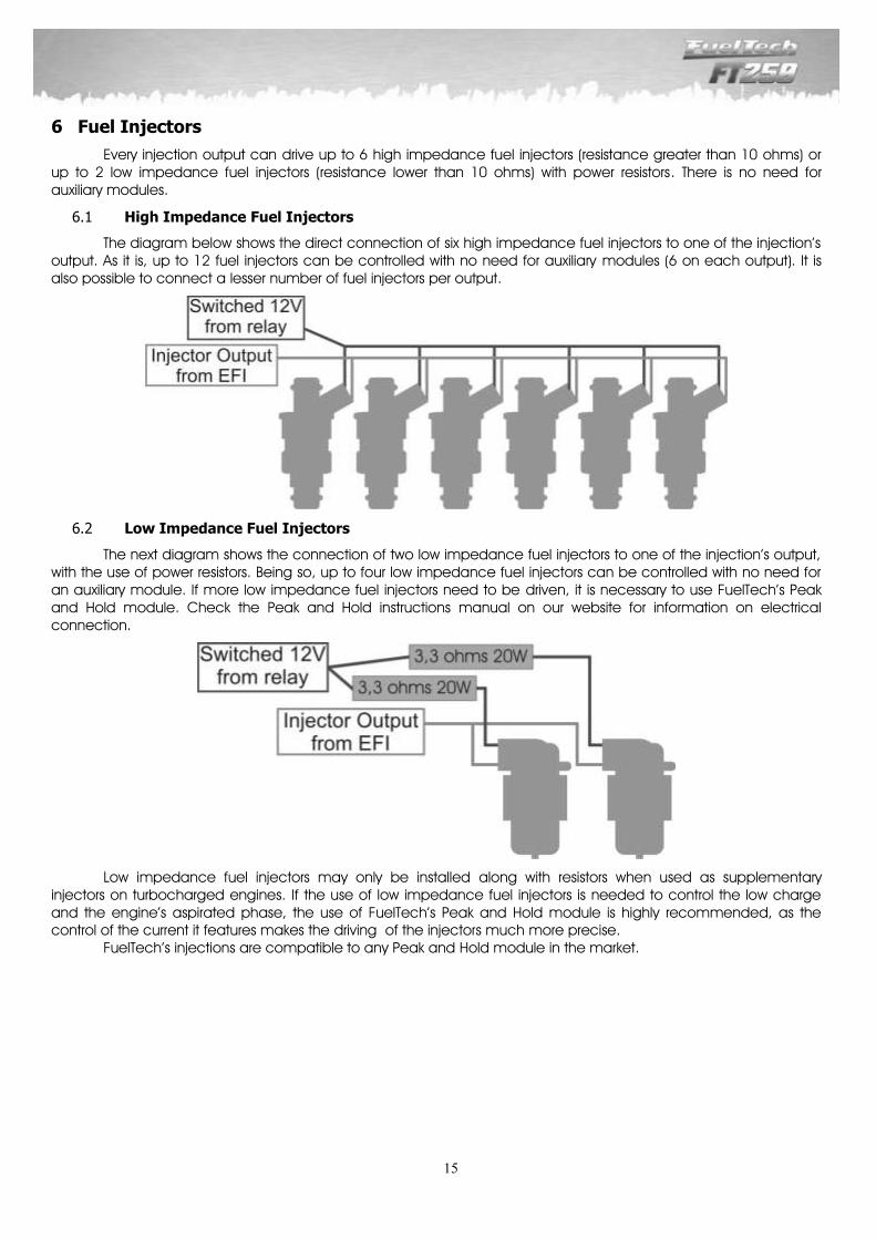
Every injection output can drive up to 6 high impedance fuel injectors (resistance greater than 10 ohms) or up to 2 low impedance fuel injectors (resistance lower than 10 ohms) with power resistors. There is no need for auxiliary modules.
High Impedance Fuel Injectors 6.1
The diagram below shows the direct connection of six high impedance fuel injectors to one of the injection’s output. As it is, up to 12 fuel injectors can be controlled with no need for auxiliary modules (6 on each output). It is also possible to connect a lesser number of fuel injectors per output.
Low Impedance Fuel Injectors 6.2
The next diagram shows the connection of two low impedance fuel injectors to one of the injection’s output, with the use of power resistors. Being so, up to four low impedance fuel injectors can be controlled with no need for an auxiliary module. If more low impedance fuel injectors need to be driven, it is necessary to use FuelTech’s Peak and Hold module. Check the Peak and Hold instructions manual on our website for information on electrical connection.
Low impedance fuel injectors may only be installed along with resistors when used as supplementary injectors on turbocharged engines. If the use of low impedance fuel injectors is needed to control the low charge and the engine’s aspirated phase, the use of FuelTech’s Peak and Hold module is highly recommended, as the control of the current it features makes the driving of the injectors much more precise. FuelTech’s injections are compatible to any Peak and Hold module in the market.
16
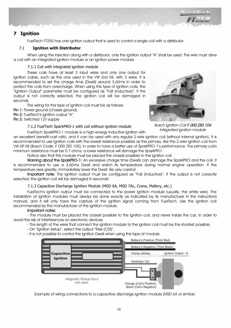
Bosch Ignition Coil F 000 ZS0 104 Integrated ignition module
7 Ignition
FuelTech FT250 has one ignition output that is used to control a single coil with a distributor.
Ignition with Distributor 7.1
When using the injection along with a distributor, only the ignition output “A” shall be used. The wire must drive a coil with an integrated ignition module or an ignition power module.
Coil with integrated ignition module 7.1.1
These coils have at least 3 input wires and only one output for ignition cable, such as the one used in the VW Gol Mi, with 3 wires. It is recommended to set the charge time (Dwell) around 3,60ms in order to protect the coils from overcharge. When using this type of ignition coils, the “Ignition Output” parameter must be configured as “Fall (inductive)”. If the output is not correctly selected, the ignition coil will be damaged in seconds. The wiring for this type of ignition coil must be as follows: Pin 1: Power ground (chassis ground) Pin 2: FuelTech’s ignition output “A” Pin 3: Switched 12V supply
FuelTech SparkPRO-1 with coil without ignition module 7.1.2
FuelTech SparkPRO-1 module is a high-energy inductive ignition with an excellent benefit-cost ratio, and it can be used with any regular 2-wire ignition coil (without internal ignition). It is recommended to use ignition coils with the lowest resistance possible as the primary, like the 2-wire ignition coil from VW AP Mi (Bosch Code: F 000 ZS0 105), in order to have a better use of SparkPRO-1’s performance. The primary coil’s minimum resistance must be 0.7 ohms; a lower resistance will damage the SparkPRO. Notice also that this module must be placed the closest possible to the ignition coil. Warning about the SparkPRO-1: An excessive charge time (Dwell) can damage the SparkPRO and the coil. It is recommended to use a 3,60ms Dwell and watch its temperature during normal engine operation. If the temperature rises greatly, immediately lower the Dwell. Be very careful! Important note: The Ignition output must be configured as “Fall (inductive)”. If the output is not correctly selected, the ignition coil will be damaged in seconds!
Capacitive Discharge Ignition Module (MSD 6A, MSD 7AL, Crane, Mallory, etc.) 7.1.3
FuelTech’s ignition output must be connected to the power ignition module (usually, the white wire). The installation of ignition modules must always be done exactly as indicated by its manufacturer in the instructions manual, and it will only have the capture of the ignition signal coming from FuelTech. Use the ignition coil recommended by the manufacturer of the ignition module. Important notes:
- The module must be placed the closest possible to the ignition coil, and never inside the car, in order to avoid the risk of interferences on electronic devices.
- The length of the wires that connect the ignition module to the ignition coil must be the shortest possible. - On “Ignition Setup”, select the output “Rise (CDI)”. - It is not possible to control the ignition Dwell when using this type of module.
Example of wiring connections to a capacitive discharge ignition module (MSD 6A or similar).
17
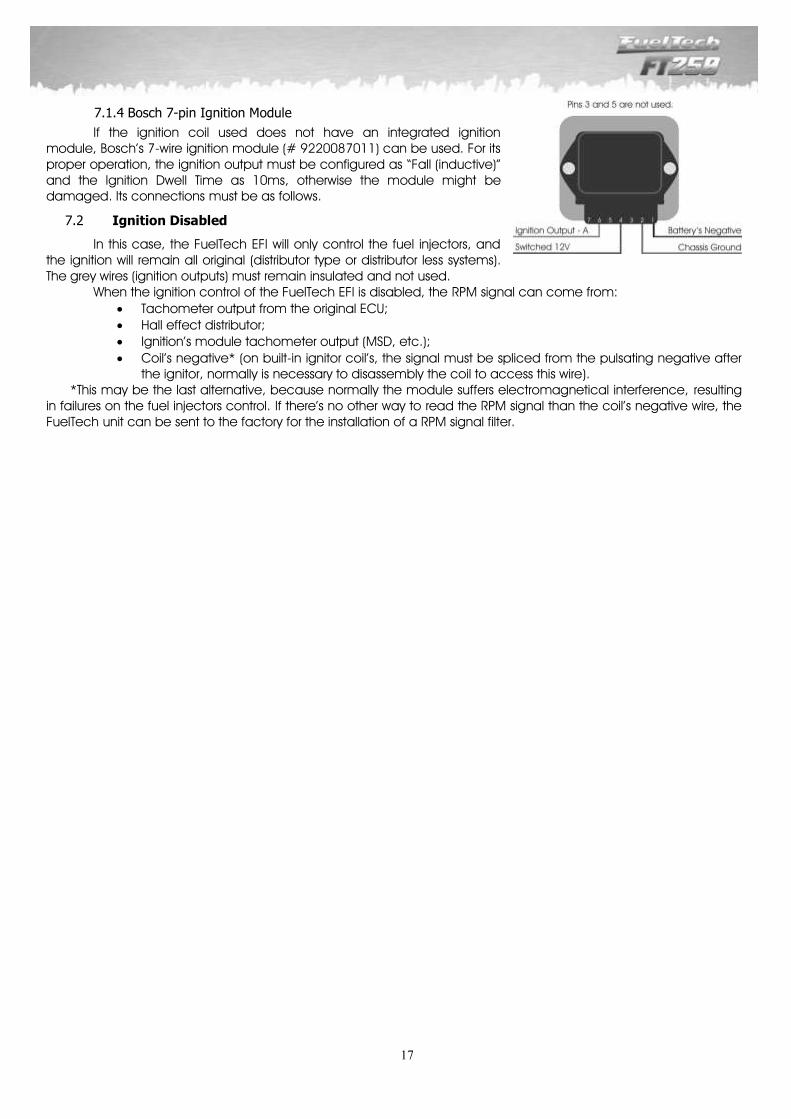
Bosch 7-pin Ignition Module 7.1.4
If the ignition coil used does not have an integrated ignition module, Bosch’s 7-wire ignition module (# 9220087011) can be used. For its proper operation, the ignition output must be configured as “Fall (inductive)” and the Ignition Dwell Time as 10ms, otherwise the module might be damaged. Its connections must be as follows.
Ignition Disabled 7.2
In this case, the FuelTech EFI will only control the fuel injectors, and the ignition will remain all original (distributor type or distributor less systems). The grey wires (ignition outputs) must remain insulated and not used.
When the ignition control of the FuelTech EFI is disabled, the RPM signal can come from:
Tachometer output from the original ECU; Hall effect distributor; Ignition’s module tachometer output (MSD, etc.);
Coil’s negative* (on built-in ignitor coil’s, the signal must be spliced from the pulsating negative after the ignitor, normally is necessary to disassembly the coil to access this wire).
*This may be the last alternative, because normally the module suffers electromagnetical interference, resulting in failures on the fuel injectors control. If there’s no other way to read the RPM signal than the coil’s negative wire, the FuelTech unit can be sent to the factory for the installation of a RPM signal filter.

18
8 Auxiliary Outputs
The current capacity of these outputs is 0.5A, and therefore they can drive solenoids or relays with 25Ω of minimum resistance. The installation of a fuse equivalent to the charge is recommended. The auxiliary outputs have an overcharge protection system, with automatic cut-off of current and the activation of charges (lamps, relays, etc.) always originated from the negative terminal. Thus, the positive terminal must be connected to a switched 12V. The yellow wires numbered 1 to 4 are the configurable auxiliary outputs. Each output must be configured in accordance to its function. For more information about the outputs programming, see chapter 15 in this manual. Notice that the configuration is not lost when the output is deactivated.
Electric Fan 8.1
This output is responsible for switching an electric fan according to the module’s settings. The relay used must be adequate to the electric fan’s current (50A, for example). The relay is switched by negative (sourced by the output), and the positive a switched 12V. Important Note: the electric fan must not be connected directly to the auxiliary output without the use of a relay; otherwise, the output will be damaged.
Idle Actuator 8.2
A valve is used to increase the air flow through intake, and therefore, increase the engine RPM. FuelTech recommends the use of an idle speed actuator that works through PWM, or a valve that is usually closed, as booster and canister solenoid valves, for example.
The relay must be adequate to the valve’s current, driven by the negative sourced by this same output. The positive for the relay must be connected to a switched 12V.
Through this setting, an alternative air passage is created, which increases the air flow to the intake manifold, even when the throttle is closed. A new airway from pressurization or air intake is opened from the engine to the intake manifold, which must pass through a solenoid valve.
As the valve does not let the air through when not activated, the system will not interfere in unwanted situations. When necessary, the valve will open the extra air passage to the engine in order to increase or maintain the idle speed RPM, according to the case.
This idle speed control helps in situations when the engine requires more air to maintain the idle speed RPM to a wanted level, such as: - Engine start: the control is activated for 3 seconds until RPM is stabilized. - Cold engine operation: control in this situation is very important, as the cold engine tends to be turned off because of its need of more air to keep operating than when hot. The opening of the valve can be regulated to a lower rpm level for when the engine is hot. - Engine operation with a higher load: for example, when the electric fan or the air-conditioning is turned on, an extra load is put on the engine, and, consequently, more air intake is needed. This control does not pulsate; therefore, it is necessary to keep a small opening on the air control valve through the screw responsible for its actuation. Such opening must be regulated as to maintain a stable idle speed when the engine is hot. If the engine RPM increases sharply when the valve is switched, a restrictive device must be put on the air passage to the valve, such as a jet hole, similar to the ones used in mechanical booster systems.
19
Shift Alert 8.3
This function activates an external shift light and works by sending negative when turned on. Any of the options below can be used:
12V light bulb up to 5W: switched 12V directly connected to the light bulb and the negative connected to the auxiliary output.
Light bulb over 5W: use a relay to switch the light bulb. LED working as a Shift Light, which must be connected with a serial resistance (if used in 12V, resistance from
390Ω to 1kΩ) to the switched 12V.
Any “Pen” Shift Light – working in the same way as a light bulb.
Fuel Pump 8.4
The fuel pump switching must be done through a relay dimensioned in accordance to the pump’s working current. The output sends out negative to activate the relay, which stays activated for 6 seconds and turns itself off if the injection does not receive any RPM signal. When the injection captures the RPM signal, it activates the fuel pump once again.
Variable Camshaft Control/Powerglide Gears 8.5
The camshaft control systems that use solenoid valve type NA/NF such as Honda’s VTEC, can be controlled through this output. The user only needs to inform the solenoid’s turn on RPM. It is important to notice that the impedance of the variable control system’s solenoid must respect the auxiliary output limits, which requires a minimum impedance of 25Ω, or the use of a relay. For valve timing control systems switched by PWM (such as Toyota’s WTi), it is possible to manage it through the Boost Control function, as long as its characteristics (power, current, etc.) are within the auxiliary output limits. This resource can also be used to switch the control solenoid from the 2-speed automatic gear control, Powerglide type. Inform the RPM to turn on the solenoid responsible for engaging the second gear.
Progressive Nitrous Control 8.6
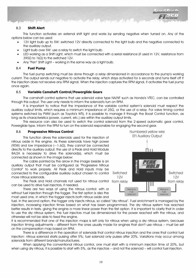
This function drives the solenoids used for the injection of nitrous oxide in the engine. As these solenoids have high power (90W) and low impedance (~1.6Ω), they cannot be connected directly to the auxiliary output; the use of a Peak and Hold Module 8A/2A is necessary to drive the solenoid(s), which must be connected as shown in the image below:
The cable pointed by the arrow in the image beside is an auxiliary output that must be configured as “Progressive Nitrous Control” to work properly. All Peak and Hold inputs may be connected to the configurable auxiliary output chosen to control more nitrous solenoids.
The Peak and Hold channels not used for nitrous control can be used to drive fuel injectors, if needed.
There are two ways of using the nitrous control: with or without fuel injection through the fogger. The first option is also the most used one, in which the fogger injects both nitrous oxide and fuel. In the second option, the fogger only injects nitrous, so called “dry nitrous”. Fuel enr ichment is managed by the injection, increasing injection times based on what has been programmed. The dry nitrous system has reached better results in tests, giving the engine a more linear power than the first option. It is important to clarify that in order to use the dry nitrous system, the fuel injectors must be dimensioned for the power reached with the nitrous, and otherwise will not be able to feed the engine. It is recommended that one of the injection maps is left only for nitrous when using a dry nitrous system, because injection timing adjustments – different from the ones usually made for engines that don’t use nitrous – must be set on the compensation map based on RPM.
There is a difference in the operation of solenoids that control nitrous injection and the ones that control fuel injection: nitrous solenoid starts pulsing after 5%; fuel solenoid only pulses after 20%. Variations may occur among solenoids from different brands/manufacturers.
When applying the conventional nitrous control, one must start with a minimum injection time of 20%, but when using dry nitrous, it is possible to start with 5%, as the injectors – and not the solenoid – will control fuel injection.
20
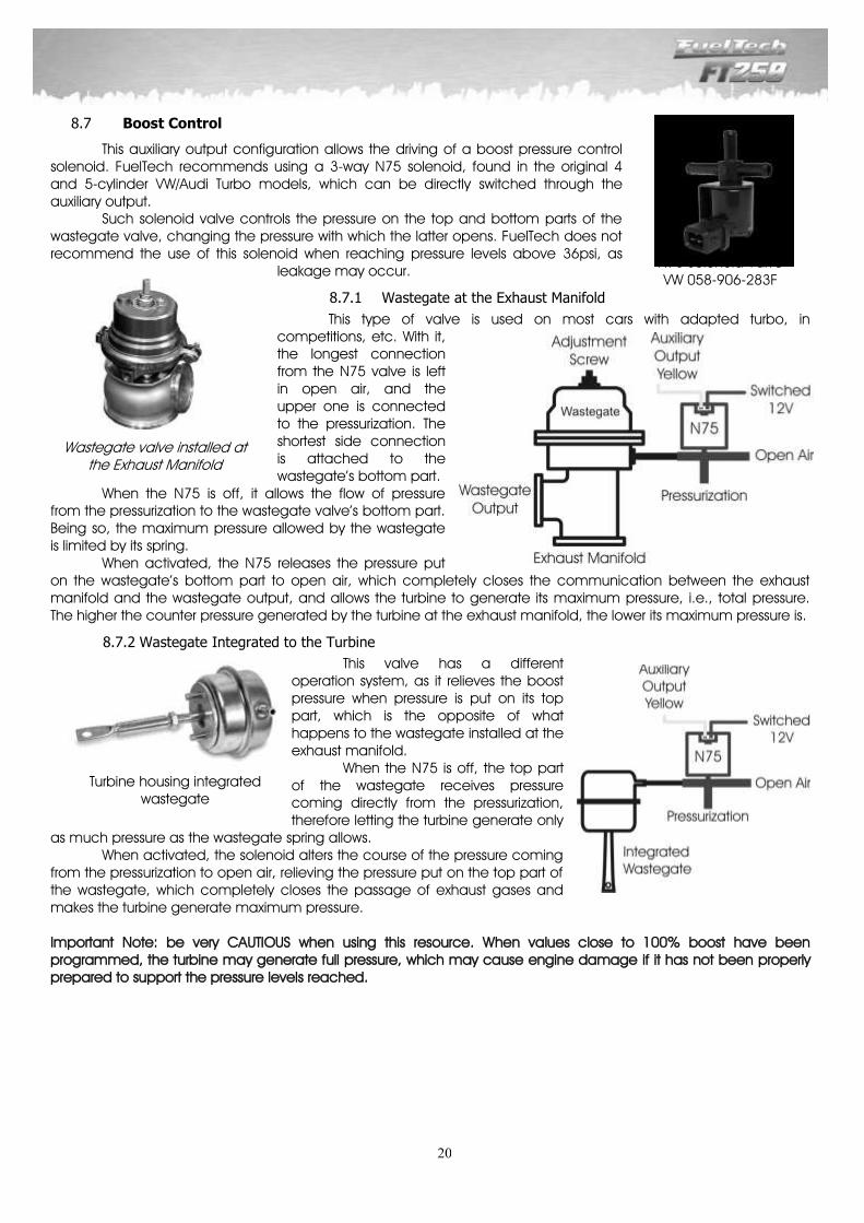
Boost Control 8.7
This auxiliary output configuration allows the driving of a boost pressure control solenoid. FuelTech recommends using a 3-way N75 solenoid, found in the original 4 and 5-cylinder VW/Audi Turbo models, which can be directly switched through the auxiliary output. Such solenoid valve controls the pressure on the top and bottom parts of the wastegate valve, changing the pressure with which the latter opens. FuelTech does not recommend the use of this solenoid when reaching pressure levels above 36psi, as
leakage may occur.
Wastegate at the Exhaust Manifold 8.7.1
This type of valve is used on most cars with adapted turbo, in competitions, etc. With it, the longest connection from the N75 valve is left in open air, and the upper one is connected to the pressurization. The shortest side connection is attached to the wastegate’s bottom part.
When the N75 is off, it allows the flow of pressure from the pressurization to the wastegate valve’s bottom part. Being so, the maximum pressure allowed by the wastegate is limited by its spring. When activated, the N75 releases the pressure put on the wastegate’s bottom part to open air, which completely closes the communication between the exhaust manifold and the wastegate output, and allows the turbine to generate its maximum pressure, i.e., total pressure. The higher the counter pressure generated by the turbine at the exhaust manifold, the lower its maximum pressure is.
Wastegate Integrated to the Turbine 8.7.2
This valve has a different operation system, as it relieves the boost pressure when pressure is put on its top part, which is the opposite of what happens to the wastegate installed at the exhaust manifold. When the N75 is off, the top part of the wastegate receives pressure coming directly from the pressurization, therefore letting the turbine generate only
as much pressure as the wastegate spring allows. When activated, the solenoid alters the course of the pressure coming from the pressurization to open air, relieving the pressure put on the top part of the wastegate, which completely closes the passage of exhaust gases and makes the turbine generate maximum pressure.
Important Note: be very CAUTIOUS when using this resource. When values close to 100% boost have been programmed, the turbine may generate full pressure, which may cause engine damage if it has not been properly prepared to support the pressure levels reached.
N75 Solenoid Valve VW 058-906-283F
Wastegate valve installed at the Exhaust Manifold
Turbine housing integrated wastegate
21
9 Using the Module
Shortcuts and Menu Navigation 9.1
To scroll among the items in the menu and to use the shortcuts, 4 buttons are used (left, right, up and down):
Left Button: used to Return or to answer No. Hold this button for 2 seconds at the dashboard screen to reset maximum and minimum values.
Right Button: used to go Forward, to Select an option or to answer Yes. Hold this button for 2 seconds at the dashboard screen to access the fuel map trim function.
Down Button: used to scroll to the menu below or to lower the selected values. Hold this button for 2 seconds at the dashboard screen to access the file quick change function.
Up Button: used to scroll to the menu above or to increase the selected values. Hold this button for 2 seconds at the dashboard screen to activate or deactivate the night mode or burnout mode.
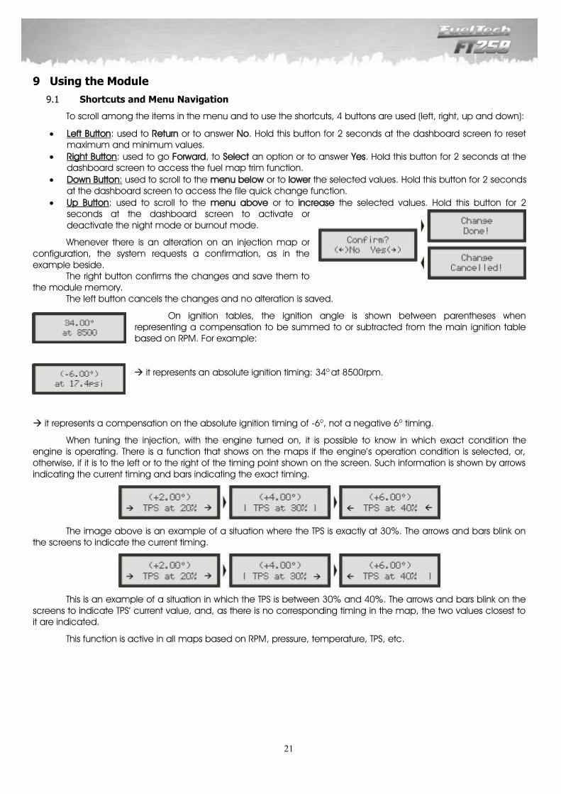
Whenever there is an alteration on an injection map or configuration, the system requests a confirmation, as in the example beside. The right button confirms the changes and save them to the module memory. The left button cancels the changes and no alteration is saved.
On ignition tables, the ignition angle is shown between parentheses when representing a compensation to be summed to or subtracted from the main ignition table based on RPM. For example:
it represents an absolute ignition timing: 34o at 8500rpm.
it represents a compensation on the absolute ignition timing of -6o, not a negative 6o timing.
When tuning the injection, with the engine turned on, it is possible to know in which exact condition the engine is operating. There is a function that shows on the maps if the engine’s operation condition is selected, or, otherwise, if it is to the left or to the right of the timing point shown on the screen. Such information is shown by arrows indicating the current timing and bars indicating the exact timing.
The image above is an example of a situation where the TPS is exactly at 30%. The arrows and bars blink on the screens to indicate the current timing.
This is an example of a situation in which the TPS is between 30% and 40%. The arrows and bars blink on the screens to indicate TPS’ current value, and, as there is no corresponding timing in the map, the two values closest to it are indicated.
This function is active in all maps based on RPM, pressure, temperature, TPS, etc.
22
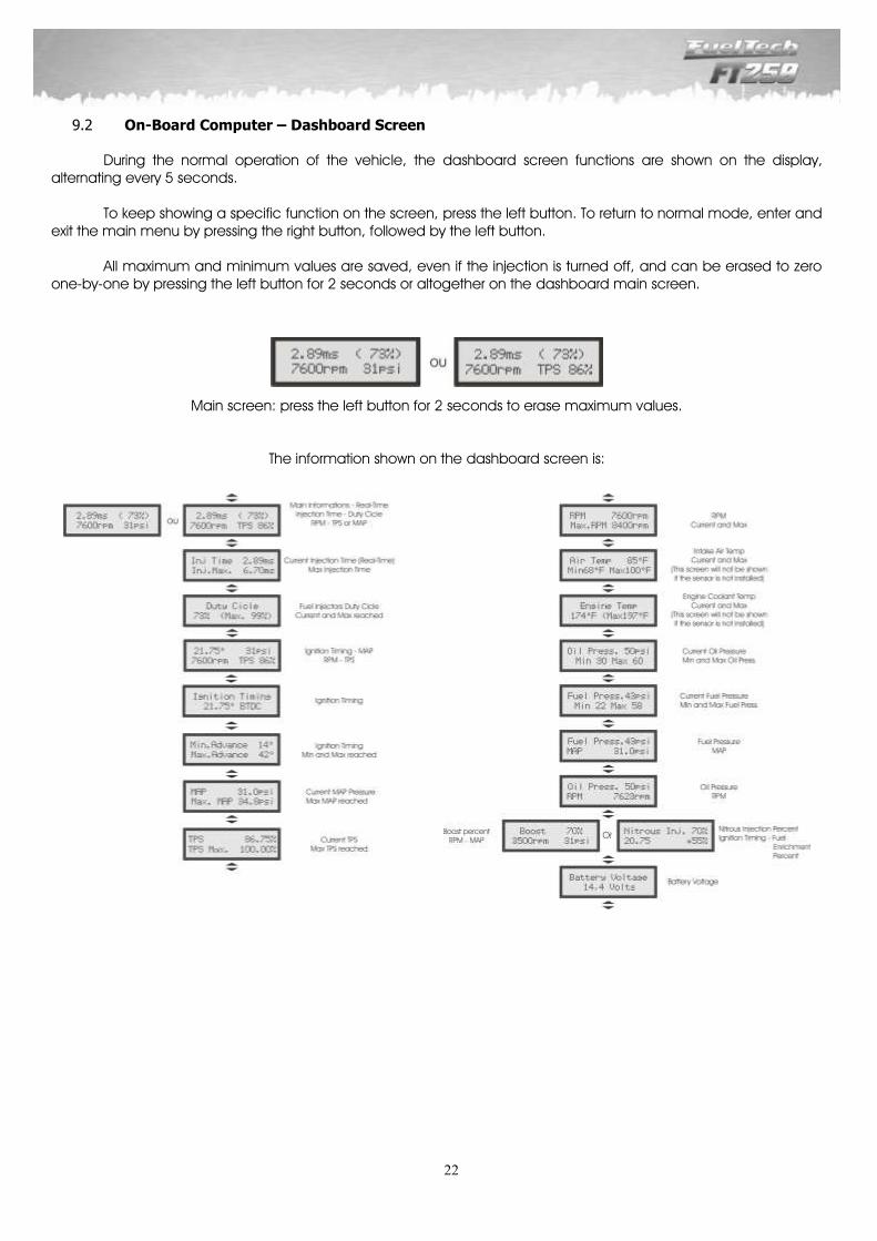
On-Board Computer – Dashboard Screen 9.2
During the normal operation of the vehicle, the dashboard screen functions are shown on the display, alternating every 5 seconds.
To keep showing a specific function on the screen, press the left button. To return to normal mode, enter and exit the main menu by pressing the right button, followed by the left button.
All maximum and minimum values are saved, even if the injection is turned off, and can be erased to zero one-by-one by pressing the left button for 2 seconds or altogether on the dashboard main screen.
Main screen: press the left button for 2 seconds to erase maximum values.
The information shown on the dashboard screen is:
23
10 Configuration and Settings – Step by Step
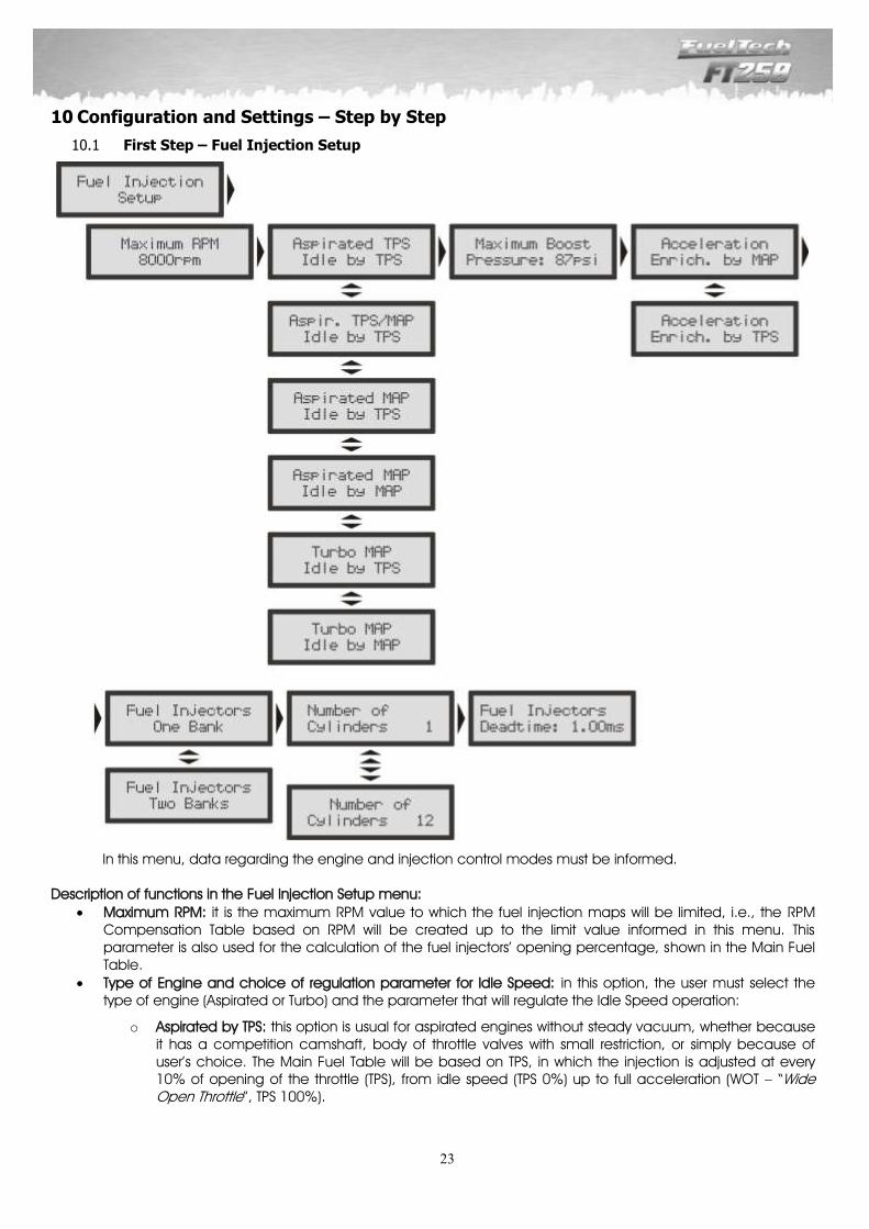
First Step – Fuel Injection Setup 10.1
In this menu, data regarding the engine and injection control modes must be informed. Description of functions in the Fuel Injection Setup menu:
Maximum RPM: it is the maximum RPM value to which the fuel injection maps will be limited, i.e., the RPM Compensation Table based on RPM will be created up to the limit value informed in this menu. This parameter is also used for the calculation of the fuel injectors’ opening percentage, shown in the Main Fuel Table.
Type of Engine and choice of regulation parameter for Idle Speed: in this option, the user must select the type of engine (Aspirated or Turbo) and the parameter that will regulate the Idle Speed operation:
o Aspirated by TPS: this option is usual for aspirated engines without steady vacuum, whether because it has a competition camshaft, body of throttle valves with small restriction, or simply because of user’s choice. The Main Fuel Table will be based on TPS, in which the injection is adjusted at every 10% of opening of the throttle (TPS), from idle speed (TPS 0%) up to full acceleration (WOT – “Wide Open Throttle”, TPS 100%).

24
o Aspirated by TPS/MAP: in this option, the Main Fuel Table will be based on TPS, but there is a compensation (in percentage) of injection by MAP, based on the intake manifold vacuum or on the atmospheric pressure only.
o Aspirated by MAP: this configuration mode is indicated for aspirated engines with steady vacuum, because the readings of the intake manifold vacuum represents the engine charge better than the opening of the throttle, especially in situations when the RPM varies, as the fix opening of the throttle can represent different levels of vacuum in the engine due to differences of flux at the throttle. Cars with competition camshaft in which the Main Fuel Table is done based on MAP, may have unstable vacuum during idle speed; in this case, FuelTech recommends that the “idle speed by TPS” option is chosen, so, when TPS readings are 0%, the fuel injection will start considering the idle speed value from the Main Fuel Table, disregarding the MAP readings.
o Turbo by MAP: in this configuration, the Main Fuel Table is a Fuel Injection x Pressure Map, beginning at -13psi up to the maximum pressure configured (up to 87psi of boost pressure, which means 101psi of absolute pressure). In turbo cars with competition camshaft, one can choose the “idle speed by TPS”, as in the previous option.
o Maximum Boost Pressure: When the car has a turbo or blown engine, this option can be configured so the Main Fuel Table is limited above pressures that will not be used. For example, in a car that will use the maximum boost pressure of 29psi, a value of 36psi can be chosen as the maximum pressure (a margin is given for regulation purposes), therefore, the Main Fuel Table will range between -13psi and 36psi, and for anything above this, the last value in the map will be considered. This parameter does not limit the pressure generated by the turbine, only the maximum value from the Main Fuel Table.
o Acceleration Enrichment: the acceleration enrichment is the increase in the amount of fuel injected when there is a quick variation of air flux in the engine. This alteration can be compensated by the injection through variation in the throttle (TPS) or in readings of vacuum/pressure in the manifold. As the throttle variation is what generates pressure alterations, the Quick Fuel Injection based on TPS tends to be more effective.
o Fuel Injector Sets:
o One Bank: the driving of the two injection outputs will happen at the same time, i.e., all injectors connected to the fuel injection system will pulsate together, at once. Then, one set of injectors can be used to feed the whole engine, from aspirated phase up to turbo maximum pressure.
o Two Banks: the control of the two injection outputs is separate, i.e., each output will have a different behavior, according to what has been programmed in the system. In aspirated engines, the second set can be used to add to or to substitute the first set of injectors (one set next to the cylinder head and the other above the throttle valves, for example). In turbo engines, one set of injectors is used to feed the engine’s aspirated phase, and the other set is used to feed the positive pressure phase.
o Number of Cylinders: the user must inform the number of cylinders in the engine. o Injection Mode: this parameter determines how the driving of injectors occurs.
o Normal: the injection pulses happen along with the ones from ignition; therefore, there is an injection pulse to each ignition pulse. This mode is used when the injectors are installed near the Throttle Body Injection (TBI).
o Alternated (recommended): in this mode, the module will release an injection pulse to every two ignition pulses. This mode must be selected when the injectors are installed near the intake valve (what is usually the standard for cars that were originally manufactured with electronic injection).
o Wasted Spark: this option is used when RPM signal is captured directly from the negative terminal of a coil working on Wasted Spark System in 4-cylinder cars, called Double Ignition Coil. The signal must be captured in this way especially in cases when the ignition system does not feature a normal RPM output. It is only used when the ignition has been disabled. The RPM is doubled as only half of it is captured.
o Synchronized: using this configuration, the fuel injection is synchronized with the engine RPM; therefore, there is one injection pulse for each engine RPM, except when there is an odd number of cylinders. This mode is very much used when the fuel injectors have a high flow rate. Only available on engines with 6 cylinders or more.
o Injectors Dead Time: all fuel injectors, for they are electromechanical valves, have an opening inertia, which means that there is a “dead time”, a moment in which the injector has already received an opening signal, but still has not started to inject fuel. This parameter considers, as a standard value, 1.00ms for high impedance fuel injectors, which is taken into account for the calculation of the injection percentage, especially for compensations or quick adjustments.
25
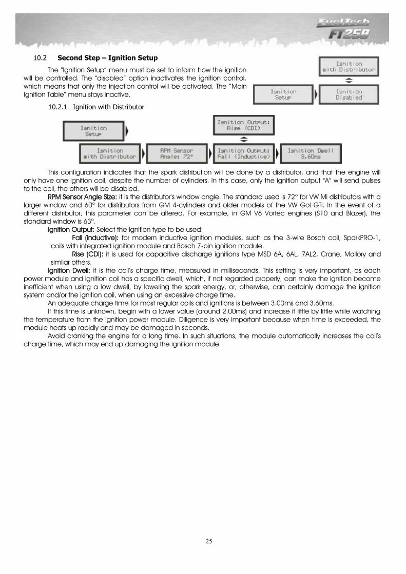
Second Step – Ignition Setup 10.2
The “Ignition Setup” menu must be set to inform how the ignition will be controlled. The “disabled” option inactivates the ignition control, which means that only the injection control will be activated. The “Main Ignition Table” menu stays inactive.
Ignition with Distributor 10.2.1
This configuration indicates that the spark distribution will be done by a distributor, and that the engine will only have one ignition coil, despite the number of cylinders. In this case, only the ignition output “A” will send pulses to the coil, the others will be disabled.
RPM Sensor Angle Size: it is the distributor’s window angle. The standard used is 72o for VW Mi distributors with a larger window and 60o for distributors from GM 4-cylinders and older models of the VW Gol GTi. In the event of a different distributor, this parameter can be altered. For example, in GM V6 Vortec engines (S10 and Blazer), the standard window is 63o.
Ignition Output: Select the ignition type to be used: Fall (inductive): for modern inductive ignition modules, such as the 3-wire Bosch coil, SparkPRO-1,
coils with integrated ignition module and Bosch 7-pin ignition module. Rise (CDI): it is used for capacitive discharge ignitions type MSD 6A, 6AL, 7AL2, Crane, Mallory and
similar others. Ignition Dwell: it is the coil’s charge time, measured in milliseconds. This setting is very important, as each
power module and ignition coil has a specific dwell, which, if not regarded properly, can make the ignition become inefficient when using a low dwell, by lowering the spark energy, or, otherwise, can certainly damage the ignition system and/or the ignition coil, when using an excessive charge time. An adequate charge time for most regular coils and ignitions is between 3.00ms and 3.60ms. If this time is unknown, begin with a lower value (around 2.00ms) and increase it little by little while watching the temperature from the ignition power module. Diligence is very important because when time is exceeded, the module heats up rapidly and may be damaged in seconds. Avoid cranking the engine for a long time. In such situations, the module automatically increases the coil’s charge time, which may end up damaging the ignition module.
26
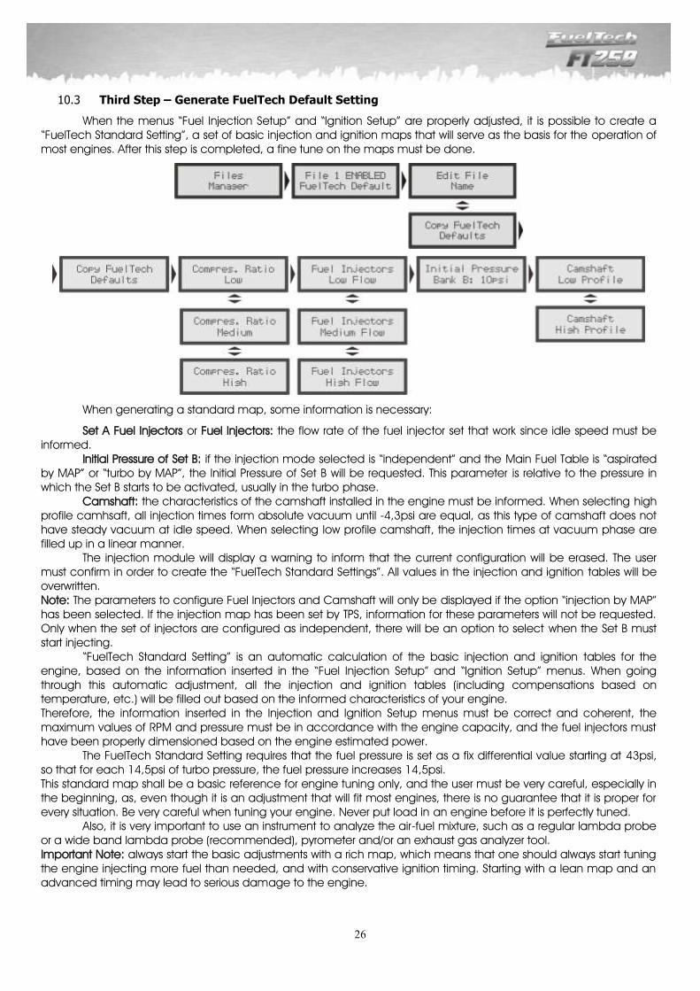
Third Step – Generate FuelTech Default Setting 10.3
When the menus “Fuel Injection Setup” and “Ignition Setup” are properly adjusted, it is possible to create a “FuelTech Standard Setting”, a set of basic injection and ignition maps that will serve as the basis for the operation of most engines. After this step is completed, a fine tune on the maps must be done.
When generating a standard map, some information is necessary:
Set A Fuel Injectors or Fuel Injectors: the flow rate of the fuel injector set that work since idle speed must be informed.
Initial Pressure of Set B: if the injection mode selected is “independent” and the Main Fuel Table is “aspirated by MAP” or “turbo by MAP”, the Initial Pressure of Set B will be requested. This parameter is relative to the pressure in which the Set B starts to be activated, usually in the turbo phase.
Camshaft: the characteristics of the camshaft installed in the engine must be informed. When selecting high profile camhsaft, all injection times form absolute vacuum until -4,3psi are equal, as this type of camshaft does not have steady vacuum at idle speed. When selecting low profile camshaft, the injection times at vacuum phase are filled up in a linear manner.
The injection module will display a warning to inform that the current configuration will be erased. The user must confirm in order to create the “FuelTech Standard Settings”. All values in the injection and ignition tables will be overwritten. Note: The parameters to configure Fuel Injectors and Camshaft will only be displayed if the option “injection by MAP” has been selected. If the injection map has been set by TPS, information for these parameters will not be requested. Only when the set of injectors are configured as independent, there will be an option to select when the Set B must start injecting.
“FuelTech Standard Setting” is an automatic calculation of the basic injection and ignition tables for the engine, based on the information inserted in the “Fuel Injection Setup” and “Ignition Setup” menus. When going through this automatic adjustment, all the injection and ignition tables (including compensations based on temperature, etc.) will be filled out based on the informed characteristics of your engine. Therefore, the information inserted in the Injection and Ignition Setup menus must be correct and coherent, the maximum values of RPM and pressure must be in accordance with the engine capacity, and the fuel injectors must have been properly dimensioned based on the engine estimated power.
The FuelTech Standard Setting requires that the fuel pressure is set as a fix differential value starting at 43psi, so that for each 14,5psi of turbo pressure, the fuel pressure increases 14,5psi. This standard map shall be a basic reference for engine tuning only, and the user must be very careful, especially in the beginning, as, even though it is an adjustment that will fit most engines, there is no guarantee that it is proper for every situation. Be very careful when tuning your engine. Never put load in an engine before it is perfectly tuned.
Also, it is very important to use an instrument to analyze the air-fuel mixture, such as a regular lambda probe or a wide band lambda probe (recommended), pyrometer and/or an exhaust gas analyzer tool. Important Note: always start the basic adjustments with a rich map, which means that one should always start tuning the engine injecting more fuel than needed, and with conservative ignition timing. Starting with a lean map and an advanced timing may lead to serious damage to the engine.
27
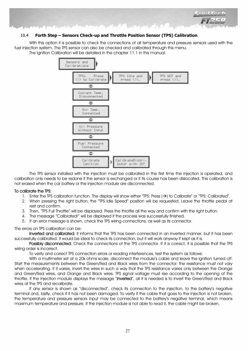
Forth Step – Sensors Check-up and Throttle Position Sensor (TPS) Calibration 10.4
With this option it is possible to check the connections of all temperature and pressure sensors used with the fuel injection system. The TPS sensor can also be checked and calibrated through this menu. The Ignition Calibration will be detailed in the chapter 11.1 in this manual.
The TPS sensor installed with the injection must be calibrated in the first time the injection is operated, and calibration only needs to be redone if the sensor is exchanged or if its course has been dislocated. This calibration is not erased when the car battery or the injection module are disconnected.
To calibrate the TPS: 1. Enter the TPS calibration function. The display will show either “TPS: Press () to Calibrate” or “TPS: Calibrated”. 2. When pressing the right button, the “TPS Idle Speed” position will be requested. Leave the throttle pedal at
rest and confirm. 3. Then, “TPS Full Throttle” will be displayed. Press the throttle all the way and confirm with the right button. 4. The message “Calibrated!” will be displayed if the process was successfully finished. 5. If an error message is shown, check the TPS wiring connections, as well as its connector.
The errors on TPS calibration can be: Inverted and calibrated: it informs that the TPS has been connected in an inverted manner, but it has been
successfully calibrated. It would be ideal to check its connection, but it will work anyway if kept as it is. Possibly disconnected: Check the connections of the TPS connector. If it is correct, it is possible that the TPS
wiring order is incorrect. To verify and correct TPS connection errors or reading interferences, test the system as follows: With a multimeter set at a 20k ohms scale, disconnect the module’s cable and leave the ignition turned off. Start the measurements between the Green/Red and Black wires from the connector: the resistance must not vary when accelerating. If it varies, invert the wires in such a way that the TPS resistance varies only between the Orange and Green/Red wires, and Orange and Black wires. TPS signal voltage must rise according to the opening of the throttle. If the injection module displays the message “inverted”, all it is needed is to invert the Green/Red and Black wires at the TPS and recalibrate. If any sensor is shown as “disconnected”, check its connection to the injection, to the battery’s negative terminal and, lastly, check if it has not been damaged. To verify if the cable that goes to the injection is not broken, the temperature and pressure sensors input may be connected to the battery’s negative terminal, which means maximum temperature and pressure. If the injection module is not able to read it, the cable might be broken.
28
11 Starting the Engine for the first time
The chapter 10 in this manual provides orientation to the user about all the necessary configurations that must be done prior to starting the engine for the first time. Only proceed in this chapter if you have already read the manual thoroughly up to this point. This will facilitate the understanding of the information in the following chapters. If there is any difficulty starting the engine for the first time, especially in cars using ethanol or methanol, inject a little gasoline. If the engine shows that it is difficult to start because of too advanced timing, retard the distributor. Also, carefully check if the ignition order is not incorrect because of an inverted ignition cable or coil connection. When the engine starts, keep it at idle speed and be attentive to the temperature of the ignition coil and the ignition power module. If it heats rapidly, turn off the engine immediately and decrease the ignition coil’s charge time. As a suggestion, the user may want to wait for the temperature to cool down before starting the engine again. Carefully check if RPM is correctly shown by the injection (with an external tachometer) and if the variations in the throttle match with the value displayed for the TPS and the vacuum readings in the dashboard screen. If strange RPM values are noticed, it certainly means that interferences are occurring when the signal is captured.
Ignition Calibration 11.1
As soon as the engine starts, before any adjustment, the ignition calibration must be done. This calibration is to make sure that the timing is happening as expected and it is reaching the engine properly. If the distributor position or any ignition configuration is not right, the ignition timing will be applied incorrectly. With the use of a timing light, it is possible to check the calibration. The ignition calibration function locks the ignition timing applied to the engine at 20o at any given RPM; therefore, if the engine starts and does not maintain at idle speed, it can be accelerated to any RPM and have the calibration done. The RPM can stay at any value, as long as it is kept with the minimum variation possible, as it may cause errors in the timing light readings. When RPM is stabilized, enter the “Ignition Calibration” option, in the “Sensors and Calibration” menu.
Calibration of Ignition with Distributor 11.1.1
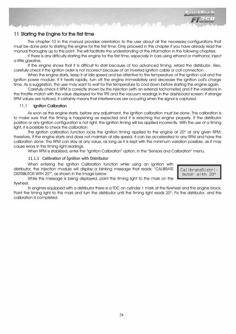
When entering the Ignition Calibration function while using an ignition with distributor, the injection module will display a blinking message that reads: “CALIBRATE DISTRIBUTOR WITH 20o”, as shown in the image below.
While this message is being displayed, point the timing light to the mark on the flywheel. In engines equipped with a distributor there is a TDC on cylinder 1 mark at the flywheel and the engine block. Point the timing light to this mark and turn the distributor until the timing light reads 20o. Fix the distributor, and the calibration is completed.
29
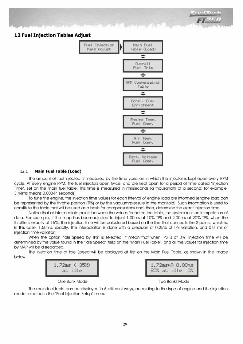
12 Fuel Injection Tables Adjust
Main Fuel Table (Load) 12.1
The amount of fuel injected is measured by the time variation in which the injector is kept open every RPM cycle. At every engine RPM, the fuel injectors open twice, and are kept open for a period of time called “Injection Time”, set on the main fuel table. This time is measured in milliseconds (a thousandth of a second; for example, 3.44ms means 0.00344 seconds). To tune the engine, the injection time values for each interval of engine load are informed (engine load can be represented by the throttle position (TPS) or by the vacuum/pressure in the manifold). Such information is used to constitute the table that will be used as a basis for compensations and, then, determine the exact injection time. Notice that at intermediate points between the values found on the table, the system runs an interpolation of data. For example, if the map has been adjusted to inject 1.00ms at 10% TPS and 2.00ms at 20% TPS, when the throttle is exactly at 15%, the injection time will be calculated based on the line that connects the 2 points, which is, in this case, 1.50ms, exactly. The interpolation is done with a precision of 0.25% of TPS variation, and 0.01ms of injection time variation. When the option “Idle Speed by TPS” is selected, it mean that when TPS is at 0%, injection time will be determined by the value found in the “Idle Speed” field on the “Main Fuel Table”, and all the values for injection time by MAP will be disregarded. The injection time at Idle Speed will be displayed at first on the Main Fuel Table, as shown in the image below.
One Bank Mode Two Banks Mode
The main fuel table can be displayed in 6 different ways, according to the type of engine and the injection mode selected in the “Fuel Injection Setup” menu.
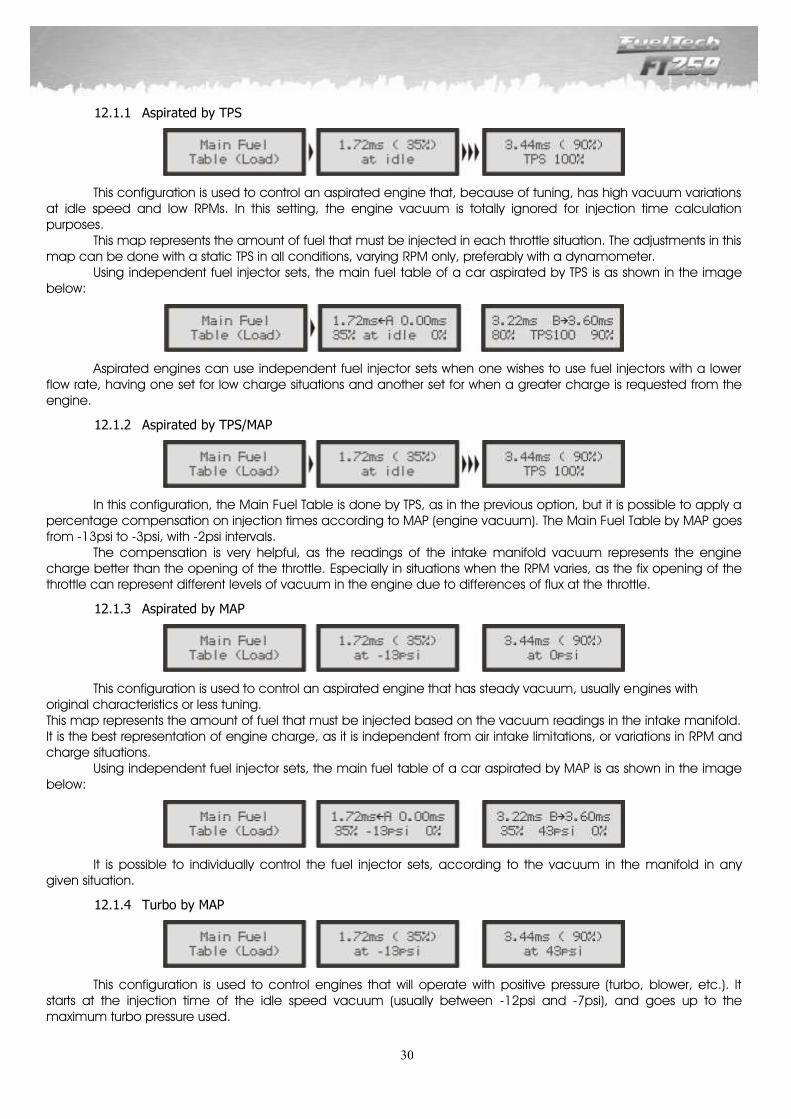
30
Aspirated by TPS 12.1.1
This configuration is used to control an aspirated engine that, because of tuning, has high vacuum variations at idle speed and low RPMs. In this setting, the engine vacuum is totally ignored for injection time calculation purposes. This map represents the amount of fuel that must be injected in each throttle situation. The adjustments in this map can be done with a static TPS in all conditions, varying RPM only, preferably with a dynamometer. Using independent fuel injector sets, the main fuel table of a car aspirated by TPS is as shown in the image below:
Aspirated engines can use independent fuel injector sets when one wishes to use fuel injectors with a lower flow rate, having one set for low charge situations and another set for when a greater charge is requested from the engine.
Aspirated by TPS/MAP 12.1.2
In this configuration, the Main Fuel Table is done by TPS, as in the previous option, but it is possible to apply a percentage compensation on injection times according to MAP (engine vacuum). The Main Fuel Table by MAP goes from -13psi to -3psi, with -2psi intervals. The compensation is very helpful, as the readings of the intake manifold vacuum represents the engine charge better than the opening of the throttle. Especially in situations when the RPM varies, as the fix opening of the throttle can represent different levels of vacuum in the engine due to differences of flux at the throttle.
Aspirated by MAP 12.1.3
This configuration is used to control an aspirated engine that has steady vacuum, usually engines with original characteristics or less tuning. This map represents the amount of fuel that must be injected based on the vacuum readings in the intake manifold. It is the best representation of engine charge, as it is independent from air intake limitations, or variations in RPM and charge situations. Using independent fuel injector sets, the main fuel table of a car aspirated by MAP is as shown in the image below:
It is possible to individually control the fuel injector sets, according to the vacuum in the manifold in any given situation.
Turbo by MAP 12.1.4
This configuration is used to control engines that will operate with positive pressure (turbo, blower, etc.). It starts at the injection time of the idle speed vacuum (usually between -12psi and -7psi), and goes up to the maximum turbo pressure used.
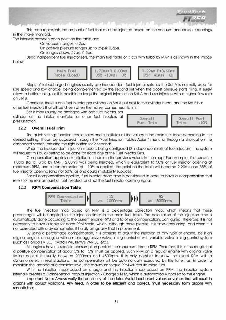
31
This map represents the amount of fuel that must be injected based on the vacuum and pressure readings in the intake manifold. The intervals between each point on the table are:
On vacuum ranges: 0,2psi. On positive pressure ranges up to 29psi: 0,3psi. On ranges above 29psi: 0,5psi.
Using independent fuel injector sets, the main fuel table of a car with turbo by MAP is as shown in the image below:
Maps of turbocharged engines usually use independent fuel injector sets, as the Set A is normally used for idle speed and low charge, being complemented by the second set when the boost pressure starts rising. It surely allows a better tuning, as it is possible to keep the original injectors on Set A and use injectors with a higher flow rate on Set B. Generally, there is one fuel injector per cylinder on Set A put next to the cylinder head, and the Set B has other fuel injectors that will be driven when the first set comes near its limit. Set B may usually be arranged with one fuel injector per cylinder at the intake manifold, or other fuel injectors at pressurization.
Overall Fuel Trim 12.2
The quick settings function recalculates and substitutes all the values in the main fuel table according to the desired setting. It can be accessed through the “Fuel Injection Tables Adjust” menu or through a shortcut on the dashboard screen, pressing the right button for 2 seconds. When the independent injection mode is being configured (2 independent sets of fuel injectors), the system will request this quick setting to be done for each one of the Fuel Injector Sets. Compensation applies a multiplication index to the previous values in the map. For example, if at pressure 1.0bar (for a Turbo by MAP), 2.00ms was being injected, which is equivalent to 50% of fuel injector opening at maximum RPM, and a compensation of +10% is applied, the point on the table will become 2.20ms and 55% of fuel injector opening (and not 60%, as one could mistakenly suppose). For all compensations applied, fuel injector dead time is considered in order to have a compensation that refers to the real amount of fuel injected, and not the fuel injector opening signal.
RPM Compensation Table 12.3
The fuel injection map based on RPM is a percentage correction map, which means that these percentages will be applied to the injection times in the main fuel table. The calculation of the injection time is automatically done according to the current engine RPM and to other compensations configured. Therefore, it is not necessary to have a table for each RPM scale, which, although more precise, it is time-consuming, and when it is not corrected with a dynamometer, it hardly brings any final improvement. By using a percentage compensation, it is possible to adjust the injection of any type of engine, be it an original engine, an engine with a more aggressive valve timing control or with variable valve timing control system (such as Honda’s VTEC, Toyota’s WTi, BMW’s VANOS, etc.). All engines have its specific consumption peak at the maximum torque RPM. Therefore, it is in this range that a positive compensation of about 5% to 15% must be applied. Such RPM on a regular engine with original valve timing control is usually between 2000rpm and 4500rpm. It is only possible to know the exact RPM with a dynamometer. In real situations, the compensation will be automatically executed by the tuner, as, in order to maintain the lambda at a constant level, the maximum torque RPM will require more fuel. With the injection map based on charge and this injection map based on RPM, the injection system internally creates a 3-dimensional map of Injection x Charge x RPM, which is automatically applied to the engine. Important Note: Always verify the continuity of the data. Avoid incoherent values or values that will result in graphs with abrupt variations. Any feed, in order to be efficient and correct, must necessarily form graphs with smooth lines.
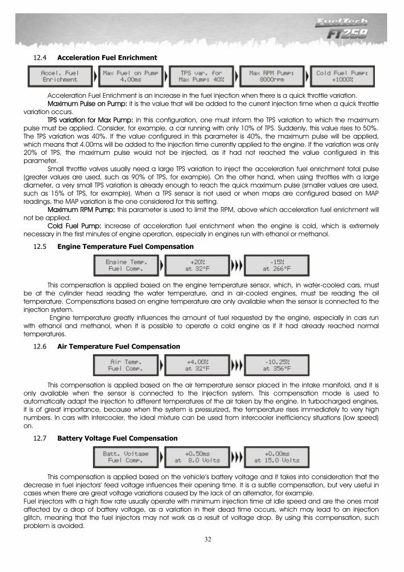
32
Acceleration Fuel Enrichment 12.4
Acceleration Fuel Enrichment is an increase in the fuel injection when there is a quick throttle variation. Maximum Pulse on Pump: it is the value that will be added to the current injection time when a quick throttle
variation occurs. TPS variation for Max Pump: in this configuration, one must inform the TPS variation to which the maximum
pulse must be applied. Consider, for example, a car running with only 10% of TPS. Suddenly, this value rises to 50%. The TPS variation was 40%. If the value configured in this parameter is 40%, the maximum pulse will be applied, which means that 4.00ms will be added to the injection time currently applied to the engine. If the variation was only 20% of TPS, the maximum pulse would not be injected, as it had not reached the value configured in this parameter. Small throttle valves usually need a large TPS variation to inject the acceleration fuel enrichment total pulse (greater values are used, such as 90% of TPS, for example). On the other hand, when using throttles with a large diameter, a very small TPS variation is already enough to reach the quick maximum pulse (smaller values are used, such as 15% of TPS, for example). When a TPS sensor is not used or when maps are configured based on MAP readings, the MAP variation is the one considered for this setting.
Maximum RPM Pump: this parameter is used to limit the RPM, above which acceleration fuel enrichment will not be applied.
Cold Fuel Pump: increase of acceleration fuel enrichment when the engine is cold, which is extremely necessary in the first minutes of engine operation, especially in engines run with ethanol or methanol.
Engine Temperature Fuel Compensation 12.5
This compensation is applied based on the engine temperature sensor, which, in water-cooled cars, must be at the cylinder head reading the water temperature, and in air-cooled engines, must be reading the oil temperature. Compensations based on engine temperature are only available when the sensor is connected to the injection system. Engine temperature greatly influences the amount of fuel requested by the engine, especially in cars run with ethanol and methanol, when it is possible to operate a cold engine as if it had already reached normal temperatures.
Air Temperature Fuel Compensation 12.6
This compensation is applied based on the air temperature sensor placed in the intake manifold, and it is only available when the sensor is connected to the injection system. This compensation mode is used to automatically adapt the injection to different temperatures of the air taken by the engine. In turbocharged engines, it is of great importance, because when the system is pressurized, the temperature rises immediately to very high numbers. In cars with intercooler, the ideal mixture can be used from intercooler inefficiency situations (low speed) on.
Battery Voltage Fuel Compensation 12.7
This compensation is applied based on the vehicle’s battery voltage and it takes into consideration that the decrease in fuel injectors’ feed voltage influences their opening time. It is a subtle compensation, but very useful in cases when there are great voltage variations caused by the lack of an alternator, for example. Fuel injectors with a high flow rate usually operate with minimum injection time at idle speed and are the ones most affected by a drop of battery voltage, as a variation in their dead time occurs, which may lead to an injection glitch, meaning that the fuel injectors may not work as a result of voltage drop. By using this compensation, such problem is avoided.
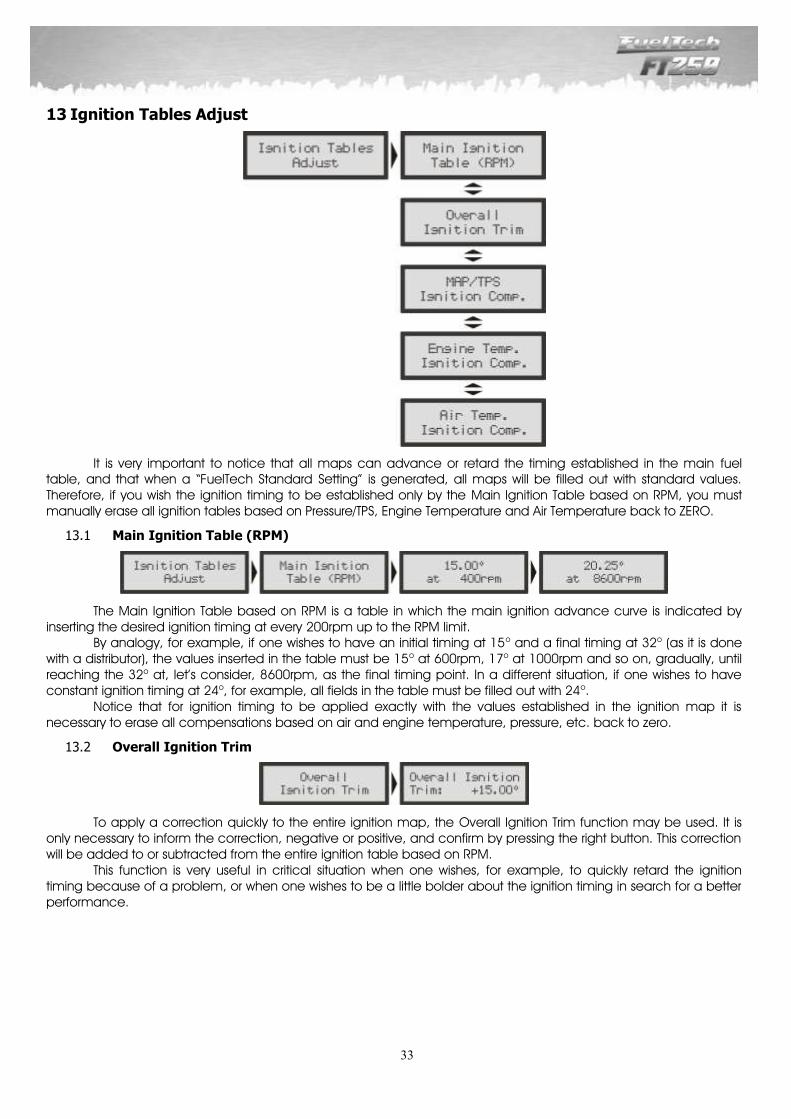
33
13 Ignition Tables Adjust
It is very important to notice that all maps can advance or retard the timing established in the main fuel table, and that when a “FuelTech Standard Setting” is generated, all maps will be filled out with standard values. Therefore, if you wish the ignition timing to be established only by the Main Ignition Table based on RPM, you must manually erase all ignition tables based on Pressure/TPS, Engine Temperature and Air Temperature back to ZERO.
Main Ignition Table (RPM) 13.1
The Main Ignition Table based on RPM is a table in which the main ignition advance curve is indicated by inserting the desired ignition timing at every 200rpm up to the RPM limit. By analogy, for example, if one wishes to have an initial timing at 15o and a final timing at 32o (as it is done with a distributor), the values inserted in the table must be 15o at 600rpm, 17o at 1000rpm and so on, gradually, until reaching the 32o at, let’s consider, 8600rpm, as the final timing point. In a different situation, if one wishes to have constant ignition timing at 24o, for example, all fields in the table must be filled out with 24o. Notice that for ignition timing to be applied exactly with the values established in the ignition map it is necessary to erase all compensations based on air and engine temperature, pressure, etc. back to zero.
Overall Ignition Trim 13.2
To apply a correction quickly to the entire ignition map, the Overall Ignition Trim function may be used. It is only necessary to inform the correction, negative or positive, and confirm by pressing the right button. This correction will be added to or subtracted from the entire ignition table based on RPM. This function is very useful in critical situation when one wishes, for example, to quickly retard the ignition timing because of a problem, or when one wishes to be a little bolder about the ignition timing in search for a better performance.
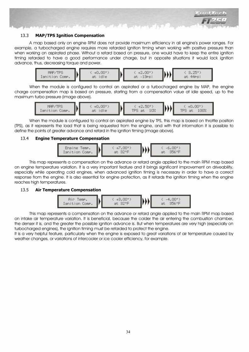
34
MAP/TPS Ignition Compensation 13.3
A map based only on engine RPM does not provide maximum efficiency in all engine’s power ranges. For example, a turbocharged engine requires more retarded ignition timing when working with positive pressure than when working on aspirated phase. Without a retard based on pressure, one would have to keep the entire ignition timing retarded to have a good performance under charge, but in opposite situations it would lack ignition advance, thus, decreasing torque and power.
When the module is configured to control an aspirated or a turbocharged engine by MAP, the engine charge compensation map is based on pressure, starting from a compensation value at idle speed, up to the maximum turbo pressure (image above).
When the module is configured to control an aspirated engine by TPS, this map is based on throttle position (TPS), as it represents the load that is being requested from the engine, and with that information it is possible to define the points of greater advance and retard in the ignition timing (image above).
Engine Temperature Compensation 13.4
This map represents a compensation on the advance or retard angle applied to the main RPM map based on engine temperature variation. It is a very important feature and it brings significant improvement on driveability, especially while operating cold engines, when advanced ignition timing is necessary in order to have a correct response from the engine. It is also essential for engine protection, as it retards the ignition timing when the engine reaches high temperatures.
Air Temperature Compensation 13.5
This map represents a compensation on the advance or retard angle applied to the main RPM map based on intake air temperature variation. It is beneficial, because the colder the air entering the combustion chamber, the denser it is, and the greater the possible ignition advance is. But when temperatures are very high (especially on turbocharged engines), the ignition timing must be retarded to protect the engine. It is a very helpful feature, particularly when the engine is exposed to great variations of air temperature caused by weather changes, or variations of intercooler or ice cooler efficiency, for example.
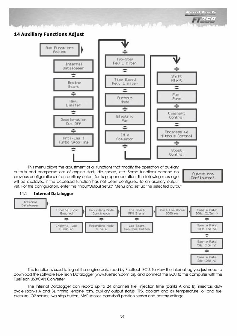
35
14 Auxiliary Functions Adjust
This menu allows the adjustment of all functions that modify the operation of auxiliary outputs and compensations of engine start, idle speed, etc. Some functions depend on previous configurations of an auxiliary output for its proper operation. The following message will be displayed if the accessed function has not been configured to an auxiliary output yet. For this configuration, enter the “Input/Output Setup” Menu and set up the selected output.
Internal Datalogger 14.1
This function is used to log all the engine data read by FuelTech ECU. To view the internal log you just need to download the software FuelTech Datalogger (www.fueltech.com.br), and connect the ECU to the computer with the FuelTech USB/CAN Converter.
The Internal Datalogger can record up to 24 channels like: injection time (banks A and B), injectors duty cycle (banks A and B), timing, engine rpm, auxiliary output status, TPS, coolant and air temperature, oil and fuel pressure, O2 sensor, two-step button, MAP sensor, camshaft position sensor and battery voltage.
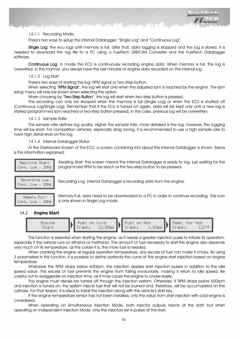
36
Recording Mode 14.1.1
There’s two ways to setup the internal Datalogger: “Single Log” and “Continuous Log”.
Single Log: the ecu logs until memory is full, after that, data logging is stopped and the log is stored. It is needed to download the log file to a PC using a FuelTech USB/CAN Converter and the FuelTech Datalogger software.
Continuous Log: in mode the ECU is continuously recording engine data. When memory is full, the log is overwrited. In this manner, you always have the last minutes of engine data recorded on the internal log.
Log Start 14.1.2
There’s two ways of starting the log: RPM signal or Two-Step button. When selecting “RPM Signal”, the log will start only when the adjusted rpm is reached by the engine. The rpm
setup menu will only be shown when selecting this option. When choosing by “Two-Step Button”, the log will start when two-step button is pressed. The recording can only be stooped when the memory is full (Single Log) or when the ECU is shutted off
(Continuous Log/Single Log). Remember that if the ECU is turned on again, data will be kept only until a new log is started (programmed rpm reached or two-step button pressed), in this case, previous log will be overwritten.
Sample Rate 14.1.3
The sample rate defines log quality. Higher the sample rate, more detailed is the log, however, the logging time will be short. For competition vehicles, especially drag racing, it is recommended to use a high sample rate to have high detail level on the log.
Internal Datalogger Status 14.1.4
At the Dashboard Screen of the ECU, a screen containing info about the Internal Datalogger is shown. Below is this information explained:
Awaiting Start: this screen means the Internal Datalogger is ready to log, just waiting for the programmed RPM to be reach or the two-step button to be pressed. Recording Log: Internal Datalogger is recording data from the engine. Memory Full, data need to be downloaded to a PC in order to continue recording. This icon is only shown in Single Log mode.
Engine Start 14.2
This function is essential when starting the engine, as it needs a greater injection pulse to initiate its operation, especially if the vehicle runs on ethanol or methanol. The amount of fuel necessary to start the engine also depends very much on its temperature, as the colder it is, the more fuel is needed. When cranking the engine at regular operation temperature, any excess of fuel can make it choke. By using 3 parameters in this function, it is possible to define perfectly the curve of the engine start injection based on engine temperature. Whenever the RPM drops below 600rpm, the injection applies start injection pulses in addition to the idle speed value. This excess of fuel prevents the engine from failing involuntarily, making it return to idle speed. Be careful not to exaggerate on injection time, as it may cause the engine to choke easily. The engine must always be turned off through the injection system. Otherwise, if RPM drops below 600rpm and injection is turned on, the system injects fuel that will not be burned and, therefore, will be accumulated on the cylinder. For that reason, it is ideal to install the injection along with the vehicle’s start key. If the engine temperature sensor has not been installed, only the value from start injection with cold engine is considered. When operating on Simultaneous Injection Mode, both injector outputs injects at the start; but when operating on Independent Injection Mode, only the injectors set A pulses at the start.
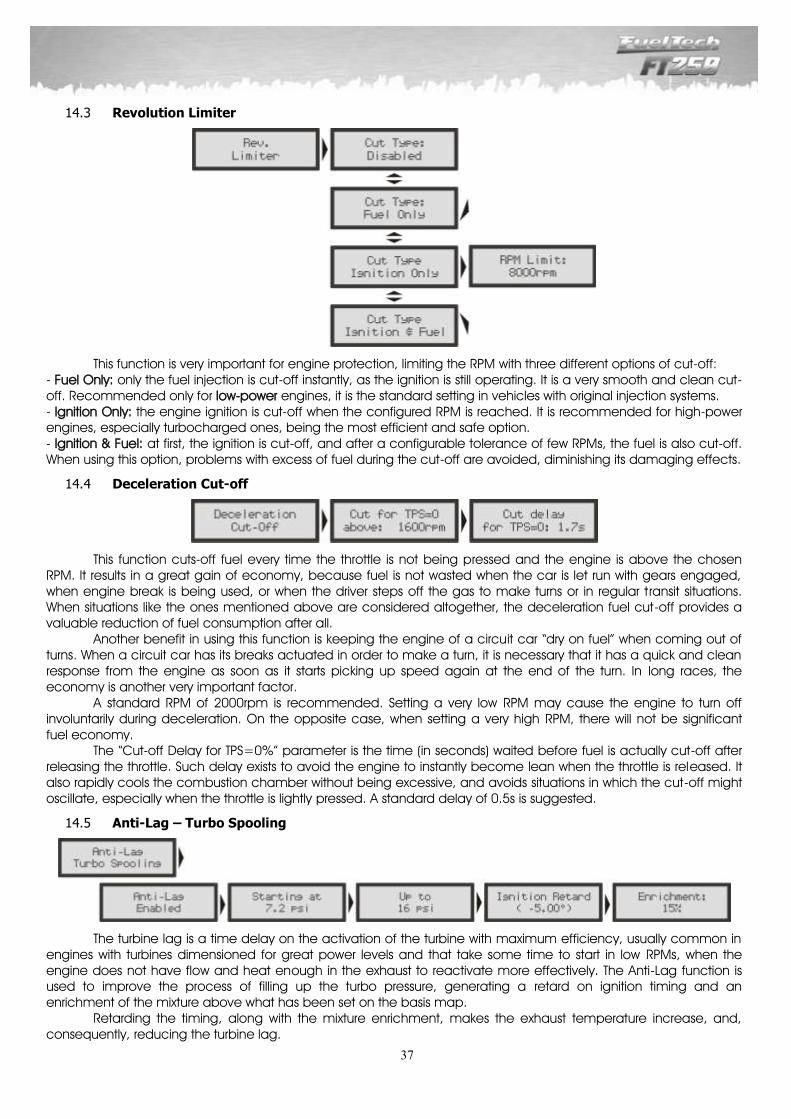
37
Revolution Limiter 14.3
This function is very important for engine protection, limiting the RPM with three different options of cut-off: - Fuel Only: only the fuel injection is cut-off instantly, as the ignition is still operating. It is a very smooth and clean cut-off. Recommended only for low-power engines, it is the standard setting in vehicles with original injection systems. - Ignition Only: the engine ignition is cut-off when the configured RPM is reached. It is recommended for high-power engines, especially turbocharged ones, being the most efficient and safe option. - Ignition & Fuel: at first, the ignition is cut-off, and after a configurable tolerance of few RPMs, the fuel is also cut-off. When using this option, problems with excess of fuel during the cut-off are avoided, diminishing its damaging effects.
Deceleration Cut-off 14.4
This function cuts-off fuel every time the throttle is not being pressed and the engine is above the chosen RPM. It results in a great gain of economy, because fuel is not wasted when the car is let run with gears engaged, when engine break is being used, or when the driver steps off the gas to make turns or in regular transit situations. When situations like the ones mentioned above are considered altogether, the deceleration fuel cut-off provides a valuable reduction of fuel consumption after all. Another benefit in using this function is keeping the engine of a circuit car “dry on fuel” when coming out of turns. When a circuit car has its breaks actuated in order to make a turn, it is necessary that it has a quick and clean response from the engine as soon as it starts picking up speed again at the end of the turn. In long races, the economy is another very important factor. A standard RPM of 2000rpm is recommended. Setting a very low RPM may cause the engine to turn off involuntarily during deceleration. On the opposite case, when setting a very high RPM, there will not be significant fuel economy. The “Cut-off Delay for TPS=0%” parameter is the time (in seconds) waited before fuel is actually cut-off after releasing the throttle. Such delay exists to avoid the engine to instantly become lean when the throttle is released. It also rapidly cools the combustion chamber without being excessive, and avoids situations in which the cut-off might oscillate, especially when the throttle is lightly pressed. A standard delay of 0.5s is suggested.
Anti-Lag – Turbo Spooling 14.5
The turbine lag is a time delay on the activation of the turbine with maximum efficiency, usually common in engines with turbines dimensioned for great power levels and that take some time to start in low RPMs, when the engine does not have flow and heat enough in the exhaust to reactivate more effectively. The Anti-Lag function is used to improve the process of filling up the turbo pressure, generating a retard on ignition timing and an enrichment of the mixture above what has been set on the basis map. Retarding the timing, along with the mixture enrichment, makes the exhaust temperature increase, and, consequently, reducing the turbine lag.
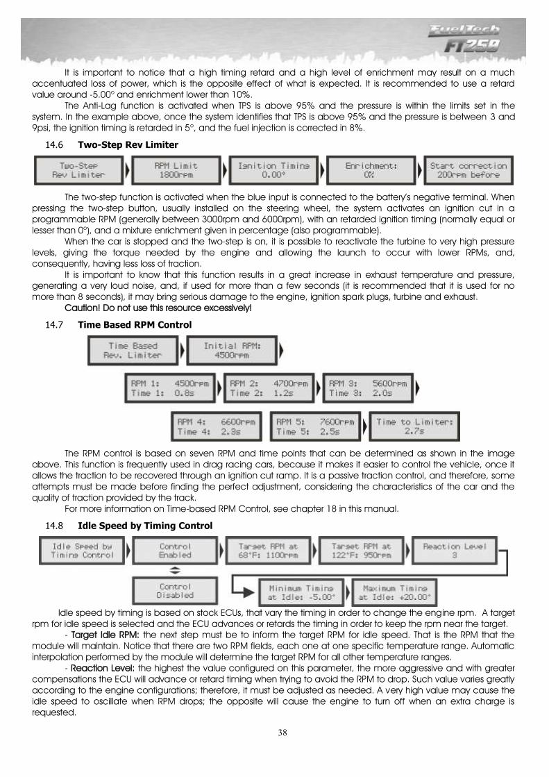
38
It is important to notice that a high timing retard and a high level of enrichment may result on a much accentuated loss of power, which is the opposite effect of what is expected. It is recommended to use a retard value around -5.00o and enrichment lower than 10%. The Anti-Lag function is activated when TPS is above 95% and the pressure is within the limits set in the system. In the example above, once the system identifies that TPS is above 95% and the pressure is between 3 and 9psi, the ignition timing is retarded in 5o, and the fuel injection is corrected in 8%.
Two-Step Rev Limiter 14.6
The two-step function is activated when the blue input is connected to the battery’s negative terminal. When pressing the two-step button, usually installed on the steering wheel, the system activates an ignition cut in a programmable RPM (generally between 3000rpm and 6000rpm), with an retarded ignition timing (normally equal or lesser than 0o), and a mixture enrichment given in percentage (also programmable). When the car is stopped and the two-step is on, it is possible to reactivate the turbine to very high pressure levels, giving the torque needed by the engine and allowing the launch to occur with lower RPMs, and, consequently, having less loss of traction. It is important to know that this function results in a great increase in exhaust temperature and pressure, generating a very loud noise, and, if used for more than a few seconds (it is recommended that it is used for no more than 8 seconds), it may bring serious damage to the engine, ignition spark plugs, turbine and exhaust. Caution! Do not use this resource excessively!
Time Based RPM Control 14.7
The RPM control is based on seven RPM and time points that can be determined as shown in the image above. This function is frequently used in drag racing cars, because it makes it easier to control the vehicle, once it allows the traction to be recovered through an ignition cut ramp. It is a passive traction control, and therefore, some attempts must be made before finding the perfect adjustment, considering the characteristics of the car and the quality of traction provided by the track. For more information on Time-based RPM Control, see chapter 18 in this manual.
Idle Speed by Timing Control 14.8
Idle speed by timing is based on stock ECUs, that vary the timing in order to change the engine rpm. A target
rpm for idle speed is selected and the ECU advances or retards the timing in order to keep the rpm near the target. - Target Idle RPM: the next step must be to inform the target RPM for idle speed. That is the RPM that the
module will maintain. Notice that there are two RPM fields, each one at one specific temperature range. Automatic interpolation performed by the module will determine the target RPM for all other temperature ranges.
- Reaction Level: the highest the value configured on this parameter, the more aggressive and with greater compensations the ECU will advance or retard timing when trying to avoid the RPM to drop. Such value varies greatly according to the engine configurations; therefore, it must be adjusted as needed. A very high value may cause the idle speed to oscillate when RPM drops; the opposite will cause the engine to turn off when an extra charge is requested.
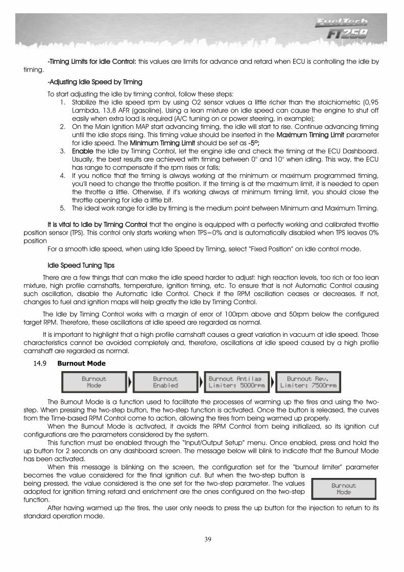
39
-Timing Limits for Idle Control: this values are limits for advance and retard when ECU is controlling the idle by
timing.
-Adjusting Idle Speed by Timing
To start adjusting the idle by timing control, follow these steps: 1. Stabilize the idle speed rpm by using O2 sensor values a little richer than the stoichiometric (0,95
Lambda, 13,8 AFR (gasoline). Using a lean mixture on idle speed can cause the engine to shut off easily when extra load is required (A/C turning on or power steering, in example);
2. On the Main Ignition MAP start advancing timing, the idle will start to rise. Continue advancing timing until the idle stops rising. This timing value should be inserted in the Maximum Timing Limit parameter for idle speed. The Minimum Timing Limit should be set as -5º;
3. Enable the Idle by Timing Control, let the engine idle and check the timing at the ECU Dashboard. Usually, the best results are achieved with timing between 0° and 10° when idling. This way, the ECU has range to compensate if the rpm rises or falls;
4. If you notice that the timing is always working at the minimum or maximum programmed timing, you’ll need to change the throttle position. If the timing is at the maximum limit, it is needed to open the throttle a little. Otherwise, if it’s working always at minimum timing limit, you should close the throttle opening for idle a little bit.
5. The ideal work range for idle by timing is the medium point between Minimum and Maximum Timing. It is vital to Idle by Timing Control that the engine is equipped with a perfectly working and calibrated throttle
position sensor (TPS). This control only starts working when TPS=0% and is automatically disabled when TPS leaves 0% position
For a smooth idle speed, when using Idle Speed by Timing, select “Fixed Position” on idle control mode. Idle Speed Tuning Tips
There are a few things that can make the idle speed harder to adjust: high reaction levels, too rich or too lean mixture, high profile camshafts, temperature, ignition timing, etc. To ensure that is not Automatic Control causing such oscillation, disable the Automatic Idle Control. Check if the RPM oscillation ceases or decreases. If not, changes to fuel and ignition maps will help greatly the Idle by Timing Control.
The Idle by Timing Control works with a margin of error of 100rpm above and 50rpm below the configured target RPM. Therefore, these oscillations at idle speed are regarded as normal.
It is important to highlight that a high profile camshaft causes a great variation in vacuum at idle speed. Those characteristics cannot be avoided completely and, therefore, oscillations at idle speed caused by a high profile camshaft are regarded as normal.
Burnout Mode 14.9
The Burnout Mode is a function used to facilitate the processes of warming up the tires and using the two-step. When pressing the two-step button, the two-step function is activated. Once the button is released, the curves from the Time-based RPM Control come to action, allowing the tires from being warmed up properly. When the Burnout Mode is activated, it avoids the RPM Control from being initialized, so its ignition cut configurations are the parameters considered by the system. This function must be enabled through the “Input/Output Setup” menu. Once enabled, press and hold the up button for 2 seconds on any dashboard screen. The message below will blink to indicate that the Burnout Mode has been activated. When this message is blinking on the screen, the configuration set for the “burnout limiter” parameter becomes the value considered for the final ignition cut. But when the two-step button is being pressed, the value considered is the one set for the two-step parameter. The values adopted for ignition timing retard and enrichment are the ones configured on the two-step function. After having warmed up the tires, the user only needs to press the up button for the injection to return to its standard operation mode.
40
Electric Fan 14.10
The electric fan control in the engine cooling system is based on the temperature in which it is expected to be activated and disabled. One can establish that the electric fan must be activated when the engine reaches 194oF and turned off when it cools to 180oF. At the “Input/Output Setup” menu, select the output that will be used for this actuator and, then, inform the chosen temperatures.
Idle Actuator 14.11
This function activates an idle speed control actuator that opens only to increase the airflow to the engine, consequently increasing RPM. At first, select the auxiliary output that will switch the solenoid at the “Input/Output Setup” menu. Then, configure the parameters shown. To cover all possible situations, there are four configuration parameters and one enrichment setting: - Turn-on actuator on crank: it is the time after starting the engine during which the actuator will be active. This parameter helps starting the engine and stabilizing idle speed after the start, which usually tends to drop, even when the engine temperature is normal. - Turn-on under (Temperature): a temperature – considered to be the one in which the engine normally operates – is chosen. If the engine is below such temperature, the actuator is kept enabled. This helps the engine to operate while cold, and, usually, the engine is not able to maintain a low idle speed. - Turn-on under (RPM): an idle speed RPM – considered to be the minimum engine RPM – is set, so when the engine drops below that, the actuator is activated for as long as what has been set in the next parameter. - Retest RPM every (“x” seconds): this is the time during which the actuator will be active; after elapsing, the actuator will be turned off. Such set up is helpful in situations when more load is put on the engine even if its operating temperature is considered normal, for example, when the electric fan or the air conditioner are turned on. - Enrichment: it controls the mixture enrichment when the valve is opened.
Shift Alert 14.12
When the engine reaches the RPM set in this parameter, the screen will display a blinking message (“SHIFT”) indicating that gear must be shifted. To switch an external shift light, it is necessary to configure an auxiliary output at the “Input/Output Setup” menu. If no auxiliary output has been configured as Shift Light, the message “Output not configured!” will be displayed. Even so, it is possible to set the Shift Light RPM on the screen.
Fuel Pump 14.13
This output activates the fuel pump through the negative terminal, connected to a relay. When starting the ignition, it is activated for six seconds, and it turns itself off if the module does not receive any RPM signal. The relay must be adequate to the current needed to switch the fuel pump.

41
Variable Camshaft Control 14.14
This function allows the control of a variable valve timing control system (or a 2-gear automatic system). Select the output used to control the camshaft solenoid, and then, inform the RPM that the solenoid must be turned on.
Progressive Nitrous Control 14.15
This auxiliary output configuration gives access to setting the ratio for the fuel-nitrous mixture (or nitrous only) through the pulse-width modulation (PWM) sent to the solenoids. The image below shows all the possible settings for this function:
Configure an auxiliary output as “Nitrous” at the “Input/Output Setup” menu. Then, select the option “Progressive Nitrous Control” at the “Input/Output Setup” menu. The first parameter to be configured is the TPS opening percentage, above which the injection of nitrous will be activated. The next parameter is the percentage of fuel enrichment for 100% nitrous. Such percentage is applied to injection times, making them longer in order to keep up with the engine. Ignition retard is a delay applied to the entire ignition table, which is necessary when there is nitrous injection. Next is the nitrous injection map based on RPM. The highest the percentage configured in this map, the greater the amount of nitrous (or nitrous + fuel) injected. The maximum RPM is the same chosen on “Fuel Injection Setup”. When using independent fuel injector sets, enrichment is done over both sets of injectors. The display below contains information about the Progressive Nitrous Control function shown on the injection’s dashboard screen. It is not possible to use Boost Control and Progressive Nitrous Control simultaneously, even when set up on different auxiliary outputs. If trying to do so, the message below is displayed:
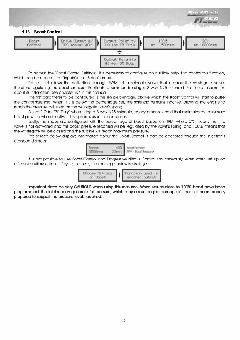
42
Boost Control 14.16
To access the “Boost Control Settings”, it is necessary to configure an auxiliary output to control this function, which can be done at the “Input/Output Setup” menu. This control allows the activation, through PWM, of a solenoid valve that controls the wastegate valve, therefore regulating the boost pressure. FuelTech recommends using a 3-way N75 solenoid. For more information about its installation, see chapter 8.7 in this manual. The first parameter to be configured is the TPS percentage, above which the Boost Control will start to pulse the control solenoid. When TPS is below the percentage set, the solenoid remains inactive, allowing the engine to reach the pressure adjusted on the wastegate valve’s spring. Select “LO for 0% Duty” when using a 3-way N75 solenoid, or any other solenoid that maintains the minimum boost pressure when inactive. This option is used in most cases. Lastly, the maps are configured with the percentage of boost based on RPM, where 0% means that the valve is not activated and the boost pressure reached will be regulated by the valve’s spring, and 100% means that the wastegate will be closed and the turbine will reach maximum pressure. The screen below displays information about the Boost Control. It can be accessed through the injection’s dashboard screen.
It is not possible to use Boost Control and Progressive Nitrous Control simultaneously, even when set up on different auxiliary outputs. If trying to do so, the message below is displayed:
Important Note: be very CAUTIOUS when using this resource. When values close to 100% boost have been programmed, the turbine may generate full pressure, which may cause engine damage if it has not been properly prepared to support the pressure levels reached.

43
15 Input/Output Setup
The “Input/Output Setup” menu includes some adjustments that are usually made by the tuner when installing the module and do not require subsequent modifications, such as the definition of installed auxiliary outputs and sensor inputs, for example. The auxiliary outputs must be previously configured in this menu in order to be accessible through the “Input/Output Setup” menu. The inputs 1 (Blue/White) and 3 (Pink) are permanently set as air temperature sensor and engine temperature sensor, respectively. The input 2 (White) may be configured as oil or fuel pressure sensor. Finally, the input 4 (Blue) can be used as oil or fuel pressure sensor, or for the two-step button (activated by negative). When a pressure sensor is selected in one of the outputs, it is also necessary to inform the type of sensor used. There are three types of pressure sensors: Siemens VDO (2-pin), PS-10A (3-pin and with “PS-10” written on its body) and PS-10B (3-pin, and with “PS-10B” written on its body). The “Engine Protection by Check Control” function automatically turns the engine off in case any warning configured at “Check Control”, under “Interfaces and Alerts”, is reached. The engine can only be turned on again after the module is restarted.

44
MAP/MAF Voltage Clamper 15.1
Wiring the clamper to the original ECU MAP sensor 15.1.1
When installing a turbocharger in an aspirated engine or increasing the pressure of turbocharged engines, some sensors from the original fuel injection control system display a failure alert. That happens because these sensors were not designed to read positive pressures. Electronically speaking, when MAP (or MAF) reads the turbo pressure, its output signal increases to a value with which the original fuel injection system is not used to working. The FT250 integrated MAP/MAF Voltage Clamper must only be used if the original ECU is still controlling some feature of the car like electronic throttle, ignition, etc. and this feature is malfunctioning. When using FT250 all stand alone, there’s no need to use the MAP/MAF Voltage Clamper.
The MAP/MAF Voltage Clamper wire is connected in parallel with the original ECU’s MAP or MAF sensor’s signal wire, preventing the sensor’s output signal from surpassing what has been configured. In other words, the clamper “clamps” the signal from the sensor making it work only within the range in which it was designed to working. If the sensor signal rises above the configured maximum, the voltage clamper drains the exceeding voltage, therefore limiting its variation range.
Identifying the MAP/MAF Sensor Signal Wire 15.1.2
The two images below show how to measure the wires from the sensor in which the clamper will be used. The wires must not be cut and, to avoid the insulation from being damaged, we recommend the use of a pin, as the multimeter leads can damage the insulation and the original wires’ connector.
In order to find the sensor’s signal wire, have the multimeter set to the 20VDC range and connect it as shown in the images above, one lead to the battery’s negative terminal and the other lead to the sensor’s wires. With the engine powered on, set the multimeter and accelerate. The voltage from the signal wire must range between 0 and 5V.
Then, connect the Green/Yellow wire to the sensor’s signal wire.
The sensor’s signal wire must not be cut. Just strip and splice it with the FT250 green/yellow wire.
Adjusting the MAP/MAF voltage 15.1.3
This menu allows the adjusment of the maximum voltage that the MAP/MAF Voltage Clamper will allow the original MAP/MAF sensor to reach. MAP: After the voltage clamper wire is connected (set the clamper voltage to 5V), keep measuring the sensor’s signal voltage with the use of a multimeter, but have the ignition key turned on and the engine powered off. The sensor will be measuring the atmospheric pressure and most likely the signal voltage will be at approximately 4.2V. Decrease the clamper voltage until the voltage read by the multimeter starts lowering. Usually, the value in which failures on MAP sensors are eliminated is a little lower than the value shown when the car is turned off. In this case, the ideal would be 4.1V. MAF: To initiate the adjustment, it is recommended to have the clamper voltage at 3V and to drive the car. In order to define the clamper voltage, the operator must find the position in which the original fuel injection system no longer detects any anomaly in the sensor when the car is moving, both in full and low throttle.
Even when that position is defined, it is still possible to modify a little the position of the regulating screw. That is because the clamper, when limiting the sensor range, induces the original fuel injection system to exclusively read the vacuum, which means that the ignition curves will also vary according to the limit value set by the voltage clamper, therefore changing the engine’s performance. It might be interesting to carry out some tests in fine tuning this adjustment. Significant improvement on the engine performance can be obtained when the MAP/MAF Voltage Clamper is well tuned.
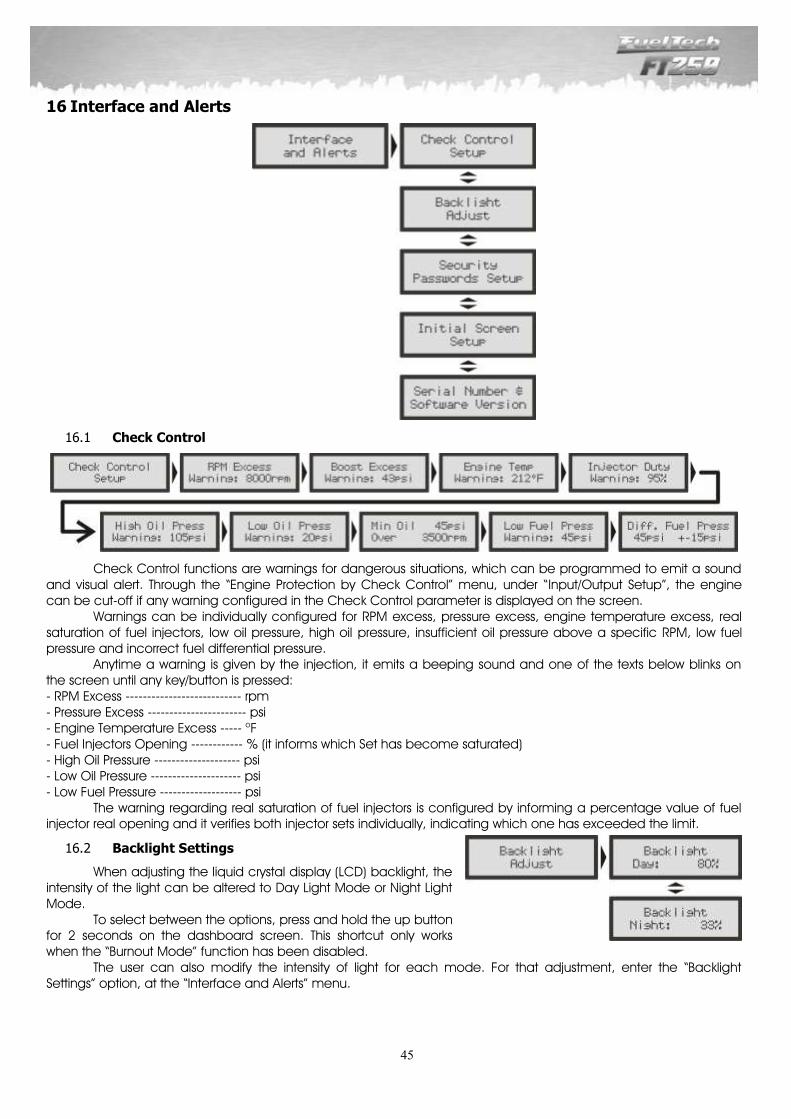
45
16 Interface and Alerts
Check Control 16.1
Check Control functions are warnings for dangerous situations, which can be programmed to emit a sound and visual alert. Through the “Engine Protection by Check Control” menu, under “Input/Output Setup”, the engine can be cut-off if any warning configured in the Check Control parameter is displayed on the screen. Warnings can be individually configured for RPM excess, pressure excess, engine temperature excess, real saturation of fuel injectors, low oil pressure, high oil pressure, insufficient oil pressure above a specific RPM, low fuel pressure and incorrect fuel differential pressure. Anytime a warning is given by the injection, it emits a beeping sound and one of the texts below blinks on the screen until any key/button is pressed: - RPM Excess --------------------------- rpm - Pressure Excess ----------------------- psi - Engine Temperature Excess ----- oF - Fuel Injectors Opening ------------ % (it informs which Set has become saturated) - High Oil Pressure -------------------- psi - Low Oil Pressure --------------------- psi - Low Fuel Pressure ------------------- psi The warning regarding real saturation of fuel injectors is configured by informing a percentage value of fuel injector real opening and it verifies both injector sets individually, indicating which one has exceeded the limit.
Backlight Settings 16.2
When adjusting the liquid crystal display (LCD) backlight, the intensity of the light can be altered to Day Light Mode or Night Light Mode. To select between the options, press and hold the up button for 2 seconds on the dashboard screen. This shortcut only works when the “Burnout Mode” function has been disabled. The user can also modify the intensity of light for each mode. For that adjustment, enter the “Backlight Settings” option, at the “Interface and Alerts” menu.
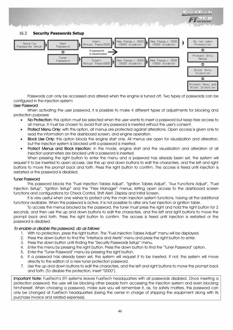
46
Security Passwords Setup 16.3
Passwords can only be accessed and altered when the engine is turned off. Two types of passwords can be configured in the injection system: User Password When activating the user password, it is possible to make 4 different types of adjustments for blocking and protection purposes:
No Protection: this option must be selected when the user wants to insert a password but keep free access to all menus. It must be chosen to avoid that any password is inserted without the user’s consent.
Protect Menu Only: with this option, all menus are protected against alterations. Open access is given only to read the information on the dashboard screen, and engine operation.
Block Use Only: this option blocks the engine start only. All menus are open for visualization and alteration, but the injection system is blocked until a password is inserted.
Protect Menus and Block Injection: in this mode, engine start and the visualization and alteration of all injection parameters are blocked until a password is inserted.
When pressing the right button to enter the menu and a password has already been set, the system will request it to be inserted to open access. Use the up and down buttons to edit the characters, and the left and right buttons to move the prompt back and forth. Press the right button to confirm. The access is freed until injection is restarted or the password is disabled.
Tuner Password This password blocks the “Fuel Injection Tables Adjust”, “Ignition Tables Adjust”, “Aux Functions Adjust”, “Fuel Injection Setup”, “Ignition Setup” and the “Files Manager” menus, letting open access to the dashboard screen functions and configurations for Check Control, Shift Alert, Display and Initial Screen. It is very useful when one wishes to protect only the main injection system functions, having all the additional functions available. When this password is active, it is not possible to alter any fuel injection or ignition table. To access the menus blocked by the password, the tuner must press the right and hold the right button for 2 seconds, and then use the up and down buttons to edit the characters, and the left and right buttons to move the prompt back and forth. Press the right button to confirm. The access is freed until injection is restarted or the password is disabled.
To enable or disable the password, do as follows: 1. With no protection, press the right button. The “Fuel Injection Tables Adjust” menu will be displayed. 2. Press the down button to find the “Interface and Alerts” menu and press the right button to enter. 3. Press the down button until finding the “Security Passwords Setup” menu. 4. Enter the menu by pressing the right button. Press the down button to find the “Tuner Password” option. 5. Enter the “Tuner Password” menu by pressing the right button. 6. If a password has already been set, the system will request it to be inserted. If not, the system will move
directly to the edition of a new tuner protection password. 7. Use the up and down buttons to edit the characters, and the left and right buttons to move the prompt back
and forth. (To disable the protection, insert “0000”).
Important Note: FuelTech’s EFI systems leaves FuelTech headquarters with all passwords disabled. Once inserting a protection password, the user will be blocking other people from accessing the injection system and even blocking him/herself. When choosing a password, make sure you will remember it, as, for safety matters, this password can only be changed at FuelTech headquarters (being the owner in charge of shipping the equipment along with its purchase invoice and related expenses).

47
Initial Screen Configuration 16.4
It is possible to customize the Initial Screen. When the injection system is turned on, the following screen is displayed indicating FuelTech’s Electronic Fuel Injection System model:
Soon after, the screen below is shown, and its standard text that can be customized according to the user’s preferences:
Serial Number and Software Version 16.5
In this menu, it is possible to verify the software version and the equipment’s serial number. Make sure to have these numbers in hand whenever the FuelTech Technical Support is contacted to facilitate and optimize the assistance.

48
17 Files Manager– Memory Positions and Functions
The Files Manager allows the user to alternate between the fuel injection maps saved in five memory positions, each one with different configurations and settings. Therefore, one could, for example, have five different settings for varied weather conditions or use. Another option is to use the same module for up to five different engines which may share the injection module but with their own adjustments and tunings saved. In that case, one or more extra cables may be requested.
File Quick Change When this function is active, through the dashboard screen, it is possible to make a quick change between settings with adjusted maps by pressing and holding the down button for two seconds.
Automatic Calculation of Fuel Injection Tables Function The function “Copy FuelTech’s Defaults” helps greatly when starting to tune a car, as it uses the data obtained from the “Fuel Injection Setup” to estimate a fuel map that will serve as a basis for the adjustments. Before using these functions it is very important that all the information and instructions given on chapter 10 in this manual have been followed thoroughly.
49
18 Time-based RPM Control
This technology results from research and development efforts carried on along with NHRA Sport Compact in the United States, with a special collaboration from Jon Perry (Gary Gardella’s Chevrolet Red Bull Racing’s crew chief), Gary Kubo (Christian Rado’s Scion’s crew chief) and the Brazilian Astra Turbo A’s drag racer Cacá Daud. It is the traction control mechanism used at NHRA Sport Compact. The Time-based RPM Control function can be used in aspirated or turbocharged engines. In the latter, the use of FuelTech BoostController along with the injection system is recommended. It is also recommended that a data acquisition system, such as FuelTech WB-O2 Data Logger, is used, as it makes possible to precisely evaluate the RPM curves, helping on fine tuning adjustments in this technology. The control starts when the two-step function is over. Thus, when the two-step button is pressed, that is the active function, but when the button is released, the time-based RPM control is initialized in accordance to the configuration set. The beginning of this control’s curve is based on a standardization of each launching, resulting on a lesser dependence on the driver’s feel when it comes to controlling the throttle – which has become a more vulnerable skill because of the ever greater engine power and quick response –, as it limits the engine RPM in order to control the wheels and tires from turning well above the vehicle’s real speed. Maximum traction is possible with the tires turning a little above real speed, and therefore, the first gear on a drag racing car is crucial, as speed starts at 0mph. Thus, for a better traction during the first few meters run by the vehicle, one must try to launch with enough engine RPM to make the wheels turn without having the engine dropping out of its torque range. Then, RPM must be maintained on a level in which the engine is still strong enough to keep the wheels turning a bit faster while the car speeds up, and soon after the RPM control must start to gradually free the RPM as the car keeps gaining speed. Without a technology like this, it is up to the driver to control the throttle during the critical moment that is the launching. But when using this function, traction is controlled by the equipment, allowing the driver to keep full throttle without the risk of losing traction. Important Notes:
A) The benefits from this control can only be noticed after some attempts and adjustments, as differences in gear, torque range and RPM range of each engine, track conditions, among other specific characteristics, require a case-by-case tuning effort.
B) When it is used along with a boost control system (FuelTech BoostController), it is recommended to slightly increase pressure on the gears in which the control is applied, as the engine needs to have some power left over so torque is not lost easily, especially because of low RPM. On the other hand, it is not recommended to have a much higher pressure than the one normally used without this resource, as it may cause the control to be too active, which can be noticed through the amount and intensity of cuts on the engine.
C) The two-step RPM is normally increased a little in order to have more power available for when the vehicle starts moving.
D) This function is only activated when the two-step button is held for more than one second. Therefore, it is possible to use the two-step as a limiter for gear shift with full TPS (as used in some cars), with no need to activate the time-based RPM control after every gear shift.
E) When final time has elapsed, the limiter returns to the Rev Limiter value programmed. F) To disable this function, set the Initial RPM as “turned off” by decreasing the RPM parameter to a value
below 1500rpm. By doing so, the Time-based RPM Control will be disabled. G) In situations when there is a session for warming up the tires, in case the two-step is used, the control can
be disabled by following the instructions above. After the warm up, the initial RPM must be set and the change confirmed, so the function will be active for launch.
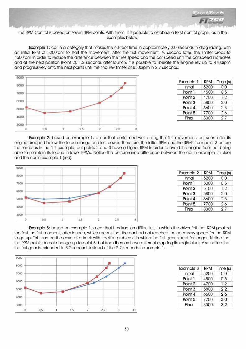
50
The RPM Control is based on seven RPM points. With them, it is possible to establish a RPM control graph, as in the examples below:
Example 1: car in a category that makes the 60-foot time in approximately 2.0 seconds in drag racing, with an initial RPM of 5200rpm to start the movement. After the first movement, ½ second later, the limiter drops to 4500rpm in order to reduce the difference between the tires speed and the car speed until the car speed increases and at the next position (Point 2), 1.2 seconds after launch, it is possible to liberate the engine rev up to 4700rpm and progressively onto the next points until the final rev limiter at 8300rpm in 2.7 seconds.
Example 2: based on example 1, a car that performed well during the first movement, but soon after its engine dropped below the torque range and lost power. Therefore, the initial RPM and the RPMs from point 3 on are the same as in the first example, but points 2 and 3 have a higher RPM in order to avoid the engine from not being able to maintain its torque in lower RPMs. Notice the performance difference between the car in example 2 (blue) and the car in example 1 (red).
Example 3: based on example 1, a car that has traction difficulties, in which the driver felt that RPM peaked too fast the first moments after launch, which means that the car had not reached the necessary speed for the RPM to go up. This can be the case of a track with traction problems in which the first gear is kept for longer. Notice that the RPM points do not change up to point 3, but from then on have different elapsing times (in blue). Also notice that the first gear is extended to 3.2 seconds instead of the 2.7 seconds in example 1.
Example 1 RPM Time (s)
Initial 5200 0.0
Point 1 4500 0.5
Point 2 4700 1.2
Point 3 5800 2.0
Point 4 6600 2.3
Point 5 7700 2.6
Final 8300 2.7
Example 2 RPM Time (s)
Initial 5200 0.0
Point 1 5000 0.5
Point 2 5100 1.2
Point 3 5800 2.0
Point 4 6600 2.3
Point 5 7700 2.6
Final 8300 2.7
Example 3 RPM Time (s)
Initial 5200 0.0
Point 1 4500 0.5
Point 2 4700 1.2
Point 3 5800 2.2
Point 4 6600 2.6
Point 5 7700 3.0
Final 8300 3.2

51
Example 4: this is an improvement of example 1. Considering that the first gear has been correctly detailed, control of the second gear will also be set. To do so, it is necessary to know in which RPM the drop resulting from the shift between first and second gears occurs, and then activate the limiter for a RPM above that level. It is also necessary to know the elapsing time in second gear, as well as the time needed for shifting gears. With that information, the RPM control for second gear makes it possible to increase engine power by increasing boost pressure during second gear, avoiding the car to lose traction when the second gear engages. Notice in the graph that the first gear has been redone with fewer points, and the points left were used for second gear.
Example 4 RPM Time (s) Description
Initial 5200 0.0 Initial movement
Point 1 4500 0.8 RPM reduction for better traction
Point 2 5700 1.2 Gradual increase of RPM with speed
Point 3 8300 2.2 First gear final limiter
Point 4 8300 2.6 Gear shift (from 2.7s to 2.9s)
Point 5 6200 3.0 RPM a little above second gear’s initial RPM
Final 8300 3.2 Second gear final time
Example 5: now, an example of a car that completed the first 60-foot in 1.5 seconds ET using slick tires,
which makes it necessary to launch with a higher RPM because of its need for more torque. So, in comparison with example 1 (of a car with radial tires), the launch RPM will probably be higher and the first gear time shorter.
Example 5 RPM Time (s)
Initial 6000 0.0
Point 1 5600 0.3
Point 2 5700 0.8
Point 3 6000 1.1
Point 4 6500 1.5
Point 5 7400 1.8
Final 8500 2.0
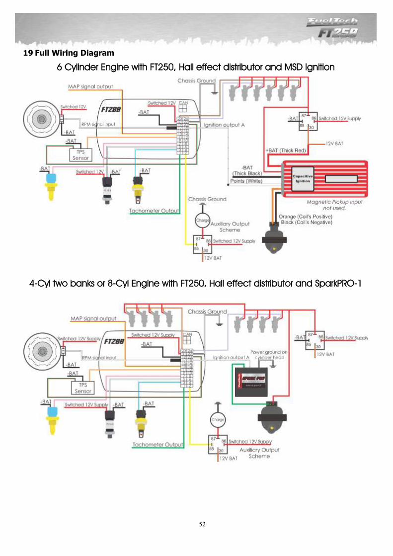
52
19 Full Wiring Diagram
6 Cylinder Engine with FT250, Hall effect distributor and MSD Ignition
4-Cyl two banks or 8-Cyl Engine with FT250, Hall effect distributor and SparkPRO-1

53
Notes
_________________________________________________________________________________________________________________________________________________________________________________________________________________________________________________________________________________________________________________________________________________________________________________________________________________________________________________________________________________________________________________________________________________________________________________________________________________________________________________________________________________________________________________________________________________________________________________________________________________________________________________________________________________________________________________________________________________________________________________________________________________________________________________________________________________________________________________________________________________________________________________________________________________________________________________________________________________________________________________________________________________________________________________________________________________________________________________________________________________________________________________________________________________________________________________________________________________________________________________________________________________________________________________________________________________________________________________________________________________________________________________________________________________________________________________________________________________________________________________________________________________________________________________________________________________________________________________________________________________________________________________________________________________________________ _________________________________________________________________
_________________________________________________________________

54
Notes
_________________________________________________________________________________________________________________________________________________________________________________________________________________________________________________________________________________________________________________________________________________________________________________________________________________________________________________________________________________________________________________________________________________________________________________________________________________________________________________________________________________________________________________________________________________________________________________________________________________________________________________________________________________________________________________________________________________________________________________________________________________________________________________________________________________________________________________________________________________________________________________________________________________________________________________________________________________________________________________________________________________________________________________________________________________________________________________________________________________________________________________________________________________________________________________________________________________________________________________________________________________________________________________________________________________________________________________________________________________________________________________________________________________________________________________________________________________________________________________________________________________________________________________________________________________________________________________________________________________________________________________________________________________________________ _________________________________________________________________
_________________________________________________________________


![[XLS] · Web view1101 0 0 0 0 11 0 0 12 0 0 13 0 0 14 0 0 15 0 0 16 0 0 17 0 0 18 0 0 19 0 0 51 1 1 0 0 81 2 0 0 3 0 0 0 0 0 0 0 0 0 0 0 0 0 0 0 0 0 1 1 0 0 2 0 0 3 0 0 0 0 0 0 0](https://img.pdfslide.us/doc/110x75/5ae8b1767f8b9a8b2b905346/xls-view1101-0-0-0-0-11-0-0-12-0-0-13-0-0-14-0-0-15-0-0-16-0-0-17-0-0-18-0-0-19.jpg)


![Clinical data successes - Joseph Paul Cohen...cat = [0 0 1 0 0 0 0 0 0 0 0 0 0 0 … 0] dog = [0 0 0 0 1 0 0 0 0 0 0 0 0 0 … 0] house = [1 0 0 0 0 0 0 0 0 0 0 0 0 0 … 0] Note!](https://img.pdfslide.us/doc/110x75/5fdf222a2dd17b0d95129a68/clinical-data-successes-joseph-paul-cohen-cat-0-0-1-0-0-0-0-0-0-0-0-0-0.jpg)
![[XLS] · Web view0 0 7/31/2018 10/16/2017 0 0 39 40 41 42 43 0 2 0 0 0 0 2 0 0 0 0 2 0 0 0 0 1 0 0 0 0 2 0 0 0 0 1 0 0 0 0 2 0 0 0 0 2 0 0 0 0 2 0 0 0 0 2 0 0 0 0 2 0 0 0 0 2 0 0](https://img.pdfslide.us/doc/110x75/5afad2057f8b9a32348e4124/xls-view0-0-7312018-10162017-0-0-39-40-41-42-43-0-2-0-0-0-0-2-0-0-0-0-2-0.jpg)


![[XLS] 7-10... · Web view1 0 0 0 2 0 0 0 3 0 0 0 4 0 0 0 5 0 0 0 6 0 0 0 7 0 0 0 8 0 0 0 9 0 0 0 10 0 0 0 11 0 0 0 12 0 0 0 13 0 0 0 14 0 0 0 15 0 0 0 16 0 0 0 17 0 0 0 18 0 0 0 19](https://img.pdfslide.us/doc/110x75/5ae8a6607f8b9a29049069b5/xls-7-10web-view1-0-0-0-2-0-0-0-3-0-0-0-4-0-0-0-5-0-0-0-6-0-0-0-7-0-0-0-8-0.jpg)