Embed Size (px)
Citation preview

Options for ABB drives, converters and inverters
User’s manualFSEA-21 sercos II adapter module

List of related manuals
You can find manuals and other product documents in PDF format on the Internet. See section Document library on the Internet on the inside of the back cover. For manuals not available in the Document library, contact your local ABB representative.
Code (EN/Multilingual)
Drive manuals and guidesACSM1 manuals 00578051
Option manuals and guidesFSEA-21 sercos II adapter module user’s manual
3AUA0000068941

6. Start-up
User’s manual
FSEA-21 sercos II adapter module
3AUA0000068941 Rev BENEFFECTIVE: 2013-11-19
2013 ABB OyAll Rights Reserved.
1. Safety
Table of contents
4. Mechanical installation
5. Electrical installation


Table of contents 5
Table of contents
1. SafetyContents of this chapter . . . . . . . . . . . . . . . . . . . . . . . . . . . . . . . . 9Use of warnings . . . . . . . . . . . . . . . . . . . . . . . . . . . . . . . . . . . . . 10Safety in installation . . . . . . . . . . . . . . . . . . . . . . . . . . . . . . . . . . 11
2. Introduction to the manualContents of this chapter . . . . . . . . . . . . . . . . . . . . . . . . . . . . . . . 13Applicability . . . . . . . . . . . . . . . . . . . . . . . . . . . . . . . . . . . . . . . . 13Compatibility . . . . . . . . . . . . . . . . . . . . . . . . . . . . . . . . . . . . . . . 13Target audience . . . . . . . . . . . . . . . . . . . . . . . . . . . . . . . . . . . . . 13Contents . . . . . . . . . . . . . . . . . . . . . . . . . . . . . . . . . . . . . . . . . . . 14Terms and abbreviations . . . . . . . . . . . . . . . . . . . . . . . . . . . . . . 15
General terms . . . . . . . . . . . . . . . . . . . . . . . . . . . . . . . . . . . 15sercos . . . . . . . . . . . . . . . . . . . . . . . . . . . . . . . . . . . . . . . . . 16General abbreviations . . . . . . . . . . . . . . . . . . . . . . . . . . . . . 18sercos abbreviations . . . . . . . . . . . . . . . . . . . . . . . . . . . . . . 18
3. Overview of the sercos network and the FSEA-21 adapter moduleContents of this chapter . . . . . . . . . . . . . . . . . . . . . . . . . . . . . . . 21sercos network . . . . . . . . . . . . . . . . . . . . . . . . . . . . . . . . . . . . . . 21
Example topology of the sercos link . . . . . . . . . . . . . . . . . . 22FSEA-21 adapter module . . . . . . . . . . . . . . . . . . . . . . . . . . . . . 22
Layout of the adapter module . . . . . . . . . . . . . . . . . . . . . . . 23
4. Mechanical installationContents of this chapter . . . . . . . . . . . . . . . . . . . . . . . . . . . . . . . 25Unpacking and examining the delivery . . . . . . . . . . . . . . . . . . . 25Installing the adapter module . . . . . . . . . . . . . . . . . . . . . . . . . . . 26
5. Electrical installationContents of this chapter . . . . . . . . . . . . . . . . . . . . . . . . . . . . . . . 29Warnings . . . . . . . . . . . . . . . . . . . . . . . . . . . . . . . . . . . . . . . . . . 29

6 Table of contents
General cabling instructions . . . . . . . . . . . . . . . . . . . . . . . . . . . . 30Connecting the FSEA-21 to the sercos network . . . . . . . . . . . . 30
Connection procedure . . . . . . . . . . . . . . . . . . . . . . . . . . . . . 31Cable attenuation . . . . . . . . . . . . . . . . . . . . . . . . . . . . . . . . . 32
6. Start-upContents of this chapter . . . . . . . . . . . . . . . . . . . . . . . . . . . . . . . 33Warnings . . . . . . . . . . . . . . . . . . . . . . . . . . . . . . . . . . . . . . . . . . 33Drive configuration . . . . . . . . . . . . . . . . . . . . . . . . . . . . . . . . . . . 34
sercos connection configuration . . . . . . . . . . . . . . . . . . . . . 34FSEA-21 configuration parameters – group A (group 1) 35
Control locations . . . . . . . . . . . . . . . . . . . . . . . . . . . . . . . . . 46Required drive parameter configuration for ACSM1 drives . . . . 46
General settings . . . . . . . . . . . . . . . . . . . . . . . . . . . . . . . . . . 46Drive-controlled homing procedure parameters . . . . . . . . . . 47Parameter for IDN S-0-0400 Home switch . . . . . . . . . . . . . 47Parameters for drive synchronization . . . . . . . . . . . . . . . . . 48Interpolator settings . . . . . . . . . . . . . . . . . . . . . . . . . . . . . . . 48Default drive control mode . . . . . . . . . . . . . . . . . . . . . . . . . . 48DCU ACT1 and ACT2 data sources . . . . . . . . . . . . . . . . . . 49Position data resolution . . . . . . . . . . . . . . . . . . . . . . . . . . . . 50
Configuring the sercos master . . . . . . . . . . . . . . . . . . . . . . . . . . 50Configuring Beckhoff TwinCAT System Manager . . . . . . . . 51
7. Communication profilesContents of this chapter . . . . . . . . . . . . . . . . . . . . . . . . . . . . . . . 57Communication profiles . . . . . . . . . . . . . . . . . . . . . . . . . . . . . . . 57sercos communication profile . . . . . . . . . . . . . . . . . . . . . . . . . . . 59
Telegram types . . . . . . . . . . . . . . . . . . . . . . . . . . . . . . . . . . 59Supported modes of operation . . . . . . . . . . . . . . . . . . . . . . . 60
Torque control operation mode . . . . . . . . . . . . . . . . . . . 61Velocity control operation mode . . . . . . . . . . . . . . . . . . . 63Position control operation mode . . . . . . . . . . . . . . . . . . . 64
Homing procedure . . . . . . . . . . . . . . . . . . . . . . . . . . . . . . . . 66Acceleration data scaling . . . . . . . . . . . . . . . . . . . . . . . . . . . 69Control word and Status word . . . . . . . . . . . . . . . . . . . . . . . 70

Table of contents 7
Real time bits . . . . . . . . . . . . . . . . . . . . . . . . . . . . . . . . . 72Transparent communication profile . . . . . . . . . . . . . . . . . . . . . . 74
8. Communication protocolContents of this chapter . . . . . . . . . . . . . . . . . . . . . . . . . . . . . . . 75Overview of communication . . . . . . . . . . . . . . . . . . . . . . . . . . . . 75Frame structure . . . . . . . . . . . . . . . . . . . . . . . . . . . . . . . . . . . . . 76Telegrams . . . . . . . . . . . . . . . . . . . . . . . . . . . . . . . . . . . . . . . . . 76
MST . . . . . . . . . . . . . . . . . . . . . . . . . . . . . . . . . . . . . . . . . . . 76MDT . . . . . . . . . . . . . . . . . . . . . . . . . . . . . . . . . . . . . . . . . . . 76AT . . . . . . . . . . . . . . . . . . . . . . . . . . . . . . . . . . . . . . . . . . . . 76
Service channel . . . . . . . . . . . . . . . . . . . . . . . . . . . . . . . . . . . . . 77IDNs . . . . . . . . . . . . . . . . . . . . . . . . . . . . . . . . . . . . . . . . . . . . . . 77sercos cycle and time parameters . . . . . . . . . . . . . . . . . . . . . . . 77Procedure commands . . . . . . . . . . . . . . . . . . . . . . . . . . . . . . . . 78Communication phases . . . . . . . . . . . . . . . . . . . . . . . . . . . . . . . 79
Communication phase 0 (CP0) . . . . . . . . . . . . . . . . . . . . . . 79Communication phase 1 (CP1) . . . . . . . . . . . . . . . . . . . . . . 79Communication phase 2 (CP2) . . . . . . . . . . . . . . . . . . . . . . 79Communication phase 3 (CP3) . . . . . . . . . . . . . . . . . . . . . . 79Communication phase 4 (CP4) . . . . . . . . . . . . . . . . . . . . . . 80
9. DiagnosticsContents of this chapter . . . . . . . . . . . . . . . . . . . . . . . . . . . . . . . 81Fault and warning messages . . . . . . . . . . . . . . . . . . . . . . . . . . . 81LEDs . . . . . . . . . . . . . . . . . . . . . . . . . . . . . . . . . . . . . . . . . . . . . 81Diagnostic IDNs . . . . . . . . . . . . . . . . . . . . . . . . . . . . . . . . . . . . . 84
Class 1 diagnostic (IDN 00011) . . . . . . . . . . . . . . . . . . . . . . 84Manufacturer class 1 diagnostic (IDN 00129) . . . . . . . . . . . 85Interface status (IDN 00014) . . . . . . . . . . . . . . . . . . . . . . . . 86Diagnostic message (IDN 00095) . . . . . . . . . . . . . . . . . . . . 87Diagnostic number (IDN 00390) . . . . . . . . . . . . . . . . . . . . . 87
Status IDNs . . . . . . . . . . . . . . . . . . . . . . . . . . . . . . . . . . . . . . . . 87Class 2 diagnostic (IDN 00012) . . . . . . . . . . . . . . . . . . . . . . 87Class 3 diagnostic (IDN 00013) . . . . . . . . . . . . . . . . . . . . . . 87

8 Table of contents
10. Technical dataContents of this chapter . . . . . . . . . . . . . . . . . . . . . . . . . . . . . . . 89FSEA-21 . . . . . . . . . . . . . . . . . . . . . . . . . . . . . . . . . . . . . . . . . . . 90sercos link . . . . . . . . . . . . . . . . . . . . . . . . . . . . . . . . . . . . . . . . . 91
11. Appendix A – USB interfaceContents of this chapter . . . . . . . . . . . . . . . . . . . . . . . . . . . . . . . 93Overview . . . . . . . . . . . . . . . . . . . . . . . . . . . . . . . . . . . . . . . . . . 93Connecting the USB cable . . . . . . . . . . . . . . . . . . . . . . . . . . . . . 94Accessing the IDN database . . . . . . . . . . . . . . . . . . . . . . . . . . . 95
12. Appendix B – Time offset adjustmentContents of this chapter . . . . . . . . . . . . . . . . . . . . . . . . . . . . . . . 97Overview of time offset adjustment . . . . . . . . . . . . . . . . . . . . . . 97Reference value time offset . . . . . . . . . . . . . . . . . . . . . . . . . . . . 99Actual value time offset . . . . . . . . . . . . . . . . . . . . . . . . . . . . . . . 99Combined effects . . . . . . . . . . . . . . . . . . . . . . . . . . . . . . . . . . . . 99Application example . . . . . . . . . . . . . . . . . . . . . . . . . . . . . . . . . 100
13. Appendix C – sercos IDNsContents of this chapter . . . . . . . . . . . . . . . . . . . . . . . . . . . . . . 103Overview of sercos IDNs . . . . . . . . . . . . . . . . . . . . . . . . . . . . . 103sercos IDNs supported by the adapter module . . . . . . . . . . . . 104IDN value storage . . . . . . . . . . . . . . . . . . . . . . . . . . . . . . . . . . 155
IDNs saved in the flash memory . . . . . . . . . . . . . . . . . . . . 156IDNs that affect ACSM1 parameters . . . . . . . . . . . . . . . . . 158
Further informationProduct and service inquiries . . . . . . . . . . . . . . . . . . . . . . . . . . 161Product training . . . . . . . . . . . . . . . . . . . . . . . . . . . . . . . . . . . . 161Providing feedback on ABB Drives manuals . . . . . . . . . . . . . . 161Document library on the Internet . . . . . . . . . . . . . . . . . . . . . . . 161

Safety 9
1Safety
Contents of this chapter
The chapter contains the warning symbols used in this manual and the safety instructions which you must obey when you install or connect an optional module to a drive, converter or inverter. If you ignore the safety instructions, injury, death or damage can occur. Read this chapter before you start the installation.

10 Safety
Use of warnings
Warnings tell you about conditions which can cause injury or death, or damage to the equipment. They also tell you how to prevent the danger. The manual uses these warning symbols:
Electricity warning tells you about hazards from electricity which can cause injury or death, or damage to the equipment.
General warning tells you about conditions, other than those caused by electricity, which can cause injury or death, or damage to the equipment.

Safety 11
Safety in installation
These warnings are intended for all who install or connect an optional module into a drive, converter or inverter, and need to open its front cover or door to perform the work.
WARNING! Obey these instructions. If you ignore them, injury or death, or damage to the equipment can occur.
• If you are not a qualified electrician, do not do installation or maintenance work.
• Disconnect the drive, converter or inverter from all possible power sources. After you have disconnected the drive, converter or inverter, always wait for 5 minutes to let the intermediate circuit capacitors discharge before you continue.
• Disconnect all dangerous voltages connected to any control signal connectors in reach. For example, it is possible that230 V AC is connected from outside to a relay output of the drive, converter or inverter.
• Always use a multimeter to make sure that there are no parts under voltage in reach. The impedance of the multimeter must be at least 1 Mohm.

12 Safety

Introduction to the manual 13
2Introduction to the manual
Contents of this chapter
This chapter introduces this manual.
Applicability
This manual applies to the FSEA-21 sercos II adapter module, SW version OFCS0125.
Compatibility
The FSEA-21 adapter module is compatible with the ACSM1 motion control program.
Target audience
This manual is intended for people who plan the installation, install, start up, use and service the adapter module. Before you do work on the adapter module, read this manual and the applicable drive/converter/inverter manual that contains the hardware and safety instructions for the product in question.
You are expected to know the fundamentals of electricity, wiring, electrical components and electrical schematic symbols.
The manual is written for readers worldwide. Both SI and imperial units are shown.

14 Introduction to the manual
Contents
The manual consists of the following chapters:• Safety presents the safety instructions which you must follow
when installing a fieldbus adapter module.
• Introduction to the manual introduces this manual.
• Overview of the sercos network and the FSEA-21 adapter module contains a short description of the sercos network and the adapter module.
• Mechanical installation contains a delivery checklist and instructions on mounting the adapter module.
• Electrical installation contains general cabling instructions and instructions on connecting the adapter module to the sercos network.
• Start-up presents the steps to take during the start-up of the drive with the adapter module and gives examples of configuring the master system.
• Communication profiles describes the communication profiles used in the communication between the sercos network, the adapter module and the drive.
• Communication protocol describes the communication on a sercos network.
• Diagnostics explains how to trace faults with the status LEDs on the adapter module.
• Technical data contains the technical data of the adapter module and the sercos link.
• Appendix A – USB interface contains instructions on how to read and write the sercos IDNs of the adapter module directly with the DriveStudio PC tool software in installations where sercos IDNs cannot be accessed through the sercos master.
• Appendix B – Time offset adjustment contains information on the time offset adjustment feature of the adapter module.
Introduction to the manual 15
• Appendix C – sercos IDNs contains a list of all sercos IDNs supported by the adapter module, and the attributes and descriptions of these IDNs.
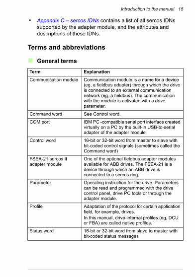
Terms and abbreviations
General terms
Term Explanation
Communication module Communication module is a name for a device (eg, a fieldbus adapter) through which the drive is connected to an external communication network (eg, a fieldbus). The communication with the module is activated with a drive parameter.
Command word See Control word.
COM port IBM PC -compatible serial port interface created virtually on a PC by the built-in USB-to-serial adapter of the adapter module
Control word 16-bit or 32-bit word from master to slave with bit-coded control signals (sometimes called the Command word)
FSEA-21 sercos II adapter module
One of the optional fieldbus adapter modules available for ABB drives. The FSEA-21 is a device through which an ABB drive is connected to a sercos ring.
Parameter Operating instruction for the drive. Parameters can be read and programmed with the drive control panel, drive PC tools or through the adapter module.
Profile Adaptation of the protocol for certain application field, for example, drives.In this manual, drive-internal profiles (eg, DCU or FBA) are called native profiles.
Status word 16-bit or 32-bit word from slave to master with bit-coded status messages

16 Introduction to the manual
sercos
Term Explanation
Attenuation Fact that the optical power at the receiver is less than at the transmitter
Broadcast Transmission to all devices in a network without any acknowledgment by the receivers
Communication cycle Accumulation of all telegrams between two master synchronization telegrams
Cycle time Time span between two consecutive cyclically recurring events
Cyclic communication Periodic exchange of telegrams
Cyclic data Part of the telegram which does not change its meaning during cyclic operation of the interface
Cyclic operation Devices in the communication network are addressed and queried one after the other at fixed, constant time intervals
Drive enable Command that allows the power stage to be activated
Drive on Command to start the drive
Drive (amplifier) telegram (AT)
Telegram sent by the drive (slave)
Identification number (IDN)
Designation of operating data under which a data block is preserved with its attribute, name, unit, minimum and maximum input values, and the data
Machine zero point Machine-related point (in each axis) to which all position data are referred
Master data telegram (MDT)
Telegram transmitted by the master sending data to the slave(s) in a single ring
Master synchronization telegram (MST)
Telegram transmitted by the master, which sends a time synchronization signal to the slave(s) in a single ring
Master Station which assigns the other stations in the ring (ie, slaves) the right to transmit
Non-cyclic transmission Non-periodic exchange of data at the request of the master

Introduction to the manual 17
Operating cycle Period of the control loop within the drive or the control unit
Protocol Convention about the data formats, time sequences, and error correction in the data exchange of communication systems
Reference point Feedback-system -related point (in each axis) to which the feedback and command values are referred to after a homing procedure
Repeater function Telegram that has been received is passed on reclocked and logically unchanged to the next station on the ring.
Ring structure Network topology in which the transmission medium is routed from station to station in the form of a ring. The information is transmitted only in one direction.
Scaling data Data which determines the weight of the transferred operation data
sercos interface Serial real-time communication system interface
Slave Device in the ring which is assigned the right to transmit by the master
Topology Physical network architecture with respect to the connection between the stations of the communication system
Transmission medium Collective term for the real form of the physical connection between the stations of a communication network (eg, fiber optic cable)
Term Explanation

18 Introduction to the manual
General abbreviations
sercos abbreviations
Abbreviation Explanation
DCU Drive Control Unit
EHCI Enhanced Host Controller Interface
FBA Field Bus Adapter
F-SMA Fiber Optic Subminiature Version A
HCS Hard clad silica (glass fiber)
IEC International Electrotechnical Commission
LSB Least significant bit
MSB Most significant bit
OHCI Open Host Controller Interface
PID Proportional / Integral / Derivative
POF Polymer optic fiber (plastic fiber)
UHCI Universal Host Controller Interface
Abbreviation Explanation
AT Drive (amplifier) telegram
C1DC2DC3D
Class 1 diagnosticClass 2 diagnosticClass 3 diagnostic
CP Communication phase
IDN Identification number
IPOSYNC Synchronization for drive interpolator
Kv (Kv-factor)
Gain of the position loop regulator
MDT Master data telegram
MST Master sync telegram
n Velocity
nmin Shut-off velocity in the drive after a C1D error
Introduction to the manual 19
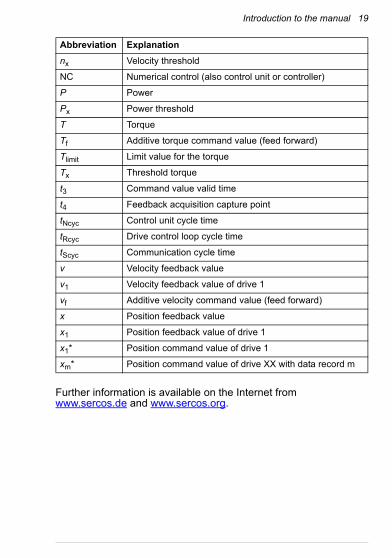
Further information is available on the Internet from www.sercos.de and www.sercos.org.
nx Velocity threshold
NC Numerical control (also control unit or controller)
P Power
Px Power threshold
T Torque
Tf Additive torque command value (feed forward)
Tlimit Limit value for the torque
Tx Threshold torque
t3 Command value valid time
t4 Feedback acquisition capture point
tNcyc Control unit cycle time
tRcyc Drive control loop cycle time
tScyc Communication cycle time
v Velocity feedback value
v1 Velocity feedback value of drive 1
vf Additive velocity command value (feed forward)
x Position feedback value
x1 Position feedback value of drive 1
x1* Position command value of drive 1
xm* Position command value of drive XX with data record m
Abbreviation Explanation

20 Introduction to the manual

Overview of the sercos network and the FSEA-21 adapter module 21
3Overview of the sercos network and the FSEA-21 adapter module
Contents of this chapter
This chapter contains a short description of the sercos network and the FSEA-21 adapter module.
sercos network
The sercos interface is a real-time industrial fieldbus specified in the IEC 61491 standard. sercos is an optical network and it uses plastic (1 mm) or glass (0.23 mm) optical fiber and F-SMA (IEC 60874-2) connectors as the transfer medium.
Optical fiber links form a ring topology, where communication is performed in cycles. The master defines a time-slot for each slave when they are allowed to transmit, at all other times slaves function as repeaters. The communication is initialized in phases from 0 to 4.
The master also defines the exact moments of time for reading the encoder position and delivering the reference value to the drive. The sercos interface provides and requires very small jitter performance at the range of a few microseconds.

22 Overview of the sercos network and the FSEA-21 adapter module
Example topology of the sercos link
An example of an allowable topology is shown below.
FSEA-21 adapter module
The FSEA-21 adapter module is an optional device for ABB drives which enables the connection of the drive to a sercos network.
Through the adapter module you can:• give control commands to the drive (for example, Start, Stop,
Run enable)
• feed a motor speed, torque or position reference to the drive
• give a process actual value or a process reference to the PID controller of the drive
• read status information and actual values from the drive
• change drive parameter values
• reset a drive fault.
The sercos commands and services supported by the adapter module are discussed in chapter Communication protocol. Refer to the user documentation of the drive as to which commands are supported by the drive.
sercos masterOther slave device ABB drive
Tx Rx RxTx

Overview of the sercos network and the FSEA-21 adapter module 23
The adapter module is installed into an option slot on the control unit of the drive. See the drive manuals for module placement options.
Layout of the adapter module
1
2 4
5
1 Mounting screw
2 Transmitter optical output
3 USB connector
4 Receiver optical input
5 Diagnostic LEDs (see chapter Diagnostics)
3

24 Overview of the sercos network and the FSEA-21 adapter module

Mechanical installation 25
4Mechanical installation
Contents of this chapter
This chapter contains a delivery checklist and instructions on mounting the adapter module.
Unpacking and examining the delivery
1. Open the option package.
2. Make sure that the package contains:
• sercos adapter module, type FSEA-21
• this manual.
3. Make sure that there are no signs of damage.

26 Mechanical installation
Installing the adapter module
WARNING! Obey the safety instructions. See chapter Safety on page 9. If you ignore the safety instructions injury or death can occur.
The adapter module is inserted into its specific position in the drive. The adapter module is held in place with plastic pins and one screw. The screw also provides the electrical connection between the adapter module and drive frame for cable shield termination.
When the adapter module is installed, the signal and power connection to the drive is made through a 20-pin connector.
When you install or remove the adapter module from a control unit:
1. Pull out the lock.
2. Insert the adapter module carefully into its position on the drive.
1

Mechanical installation 27
3. Push in the lock.
4. Tighten the screw.
Note: It is essential to install the screw properly to fulfill the EMC requirements and to ensure the proper operation of the adapter module.
See the appropriate drive manual for instructions on how to install the adapter module to the drive.
3
4

28 Mechanical installation

Electrical installation 29
5Electrical installation
Contents of this chapter
This chapter contains:• general cabling instructions
• instructions on connecting the adapter module to the sercos network.
Warnings
WARNING! Obey the safety instructions. See chapter Safety on page 9. If you ignore the safety instructions, injury or death can occur. If you are not a qualified
electrician, do not do electrical work.

30 Electrical installation
General cabling instructions• Route the bus cables as far away from the motor cables as
possible.
• Avoid parallel runs.
• Use bushings at cable entries.
When you connect the network cables, carefully insert the cable so that the plug enters the jack straightly without any misalignment and without applying any twisting or bending moments to the cable or the plug. Do not use excessive force. Make sure that the plug latches into place and finally check that the plug has entered all the way into the jack.
Route the cables so that they do not transmit bending stress to the connector.
The drive must be installed so that there is enough room (15 cm) for the network cables so that the cables can be easily connected and disconnected and the cables need not go through an unreasonably small bending radius.
Connecting the FSEA-21 to the sercos network
The connectors used for sercos fiber optic cables should be F-SMA type with quality level 5 or greater and have a metallic outer ring. It is also recommended that the connectors have a strain relief to protect the cable.
Two types of fiber cables are available for sercos networks: plastic optical fiber (POF) and hard clad glass silica (HCS) fiber cables. The fiber optic cables require special care during installation to ensure reliable operation. Cable manufacturer's guidelines on bend radius, twisting and tensile loads, squeezing and pinching must be followed.
General advice on fiber optic cable handling:• Avoid a small bending radius and sharp corners.
• Do not twist, squeeze or pinch the fibers.
• Protect the connectors from impurities and scratching.
ABB can only guarantee correct and reliable operation of the adapter module if all other equipment installed on the sercos

Electrical installation 31
network has been approved by sercos international and suitable fiber optic cables and connectors are used.
Connection procedure
1. Connect an optical fiber from the TX connector of the previous slave or the master (if this adapter module is the first slave on the ring) to RX connector (V2) of the adapter module.
2. Fasten the tightening nuts.
3. Connect another optical fiber from the TX connector (V1) of the adapter module to the RX connector of the next slave on the ring or the master (if this module is the last slave on the ring).
4. Fasten the tightening nuts.
ABB drive ABB driveABB drive
sercos master
RX TX
TX TXRX RXTX RX

32 Electrical installation
Cable attenuation
Modern optical fiber cables have attenuation of approximately 200…300 dB/km for POF and 7…10 dB/km for HCS at wavelength of 650 nm. Especially when using POF cabling, the connection length dramatically affects transmission power margins. Because of over-drive limitations, too high transmission power is not acceptable either.
sercos does not specify any automatic transmission power adjustment. Therefore, adjust the transmission power to roughly match the length of the cable installed to the transmitter of the adapter module. The adapter module provides four choices for the transmission power which can be adjusted by a drive parameter (par. 51.04 in the ACSM1). See parameter 04 TX POWER.
A small bending radius increases attenuation. For example, a 90-degrees corner with a radius of 15 mm on a 1 mm POF cable may increase attenuation roughly 0.4 dB. Poorly installed fiber connectors or impurities also add attenuation.

Start-up 33
6Start-up
Contents of this chapter
This chapter contains:• information on configuring the drive for operation with the
adapter module
• drive-specific instructions on starting up the drive with the adapter module
• examples of configuring the master station for communication with the adapter module.
Warnings
WARNING! Obey the safety instructions given in this manual and the drive documentation.

34 Start-up
Drive configuration
The following information applies only to ACSM1 drives.
sercos connection configuration
After the adapter module has been mechanically and electrically installed according to the instructions in chapters Mechanical installation and Electrical installation, the drive must be prepared for communication with the module.
The detailed procedure of activating the module for sercos communication with the drive depends on the drive type. Normally, a parameter must be adjusted to activate the communication. See section Required drive parameter configuration for ACSM1 drives.
Once communication between the drive and the adapter module has been established, several configuration parameters are copied to the drive. These parameters are shown in the tables below and must be checked first and adjusted where necessary.
Note: To help you identify the parameters in the ACSM1, the names displayed by the drive are given in grey boxes in the tables.
In addition to the essential communication settings of the sercos ring, some of the sercos IDNs are also stored in the same parameter group so that they can be configured through the drive parameter interface. Other sercos IDNs can be changed and monitored via the sercos master or through the USB interface by using the DriveStudio software.
Note: The new settings take effect only when the adapter module is powered up the next time or when the fieldbus adapter refresh parameter is activated. In the ACSM1, the parameters are refreshed by parameter setting 51.27 FBA PAR REFRESH = REFRESH.
Note: Parameter settings take effect when the corresponding data is used the next time. For example, sercos address and bit rate settings take effect when the sercos interface is re-initialized.
Start-up 35
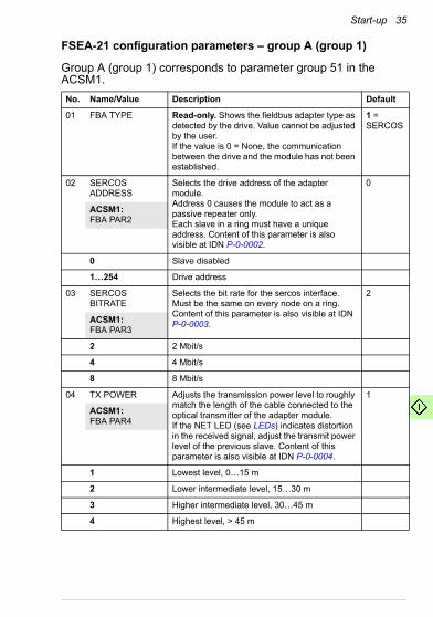
FSEA-21 configuration parameters – group A (group 1)
Group A (group 1) corresponds to parameter group 51 in the ACSM1.
No. Name/Value Description Default
01 FBA TYPE Read-only. Shows the fieldbus adapter type as detected by the drive. Value cannot be adjusted by the user. If the value is 0 = None, the communication between the drive and the module has not been established.
1 = SERCOS
02 SERCOS ADDRESS
Selects the drive address of the adapter module.Address 0 causes the module to act as a passive repeater only.Each slave in a ring must have a unique address. Content of this parameter is also visible at IDN P-0-0002.
0
ACSM1: FBA PAR2
0 Slave disabled
1…254 Drive address
03 SERCOS BITRATE
Selects the bit rate for the sercos interface. Must be the same on every node on a ring.Content of this parameter is also visible at IDN P-0-0003.
2
ACSM1: FBA PAR3
2 2 Mbit/s
4 4 Mbit/s
8 8 Mbit/s
04 TX POWER Adjusts the transmission power level to roughly match the length of the cable connected to the optical transmitter of the adapter module.If the NET LED (see LEDs) indicates distortion in the received signal, adjust the transmit power level of the previous slave. Content of this parameter is also visible at IDN P-0-0004.
1
ACSM1: FBA PAR4
1 Lowest level, 0…15 m
2 Lower intermediate level, 15…30 m
3 Higher intermediate level, 30…45 m
4 Highest level, > 45 m

36 Start-up
05 PROFILE Selects the communication profile used by the adapter module.Note: If mode 1 is selected, the operation is not compliant with the sercos specification.Content of this parameter is also visible at IDN P-0-0005. For more information on the communication profiles, see chapter Communication profiles.
0
ACSM1: FBA PAR5
0 sercos
1 Transparent
06 DRIVE SYNC POS
Selects the point of the sercos cycle, where the drive software is synchronized to. sercos master determines two time instants within the communication cycle, called t3 and t4. Definitions: t3 = command value valid time (the time at which the drive is allowed to access the new command values after reception of the MDT). t4 = feedback acquisition capture time (the sampling point of the feedback, eg, axis actual position).With the ACSM1, only one of these timing requirements can be obeyed at a time. t3 sync means that the reference value is delivered to the drive exactly at the correct time, but feedback acquisition time may not match the time specified by the master. t4 sync means that feedback acquisition takes place exactly at the correct time but the reference values may be taken into use in the drive at a different time than that specified by the master.Content of this parameter is also visible at IDN P-0-0006.
3
ACSM1: FBA PAR6
0 No synchronization
3 Synchronization to t3 point of the sercos cycle
4 Synchronization to t4 point of the sercos cycle
No. Name/Value Description Default

Start-up 37
07 REF SEND TIME sercos time parameters normally determine when the module sends the reference to the drive to meet the timing requirements set forth by the master. However, there are applications where the reference values should be taken into use in the drive as soon as possible, ignoring all the other, possibly slower, drives on the same ring.Selects whether command values are sent to the drive at the time specified by the timing calculation performed by the module to obtain correct drive performance in relation to the selected synchronization mode, or whether they are sent immediately after the MDT – as soon as command values are in the IDN database of the module.Note: If mode 1 is selected, the operation is not compliant with the sercos specification.Content of this parameter is also visible at IDN P-0-0007.
0
ACSM1: FBA PAR7
0 Normal mode (sercos compliant)
1 Immediate (reference sent to the drive as soon as MDT data is received)
08 CP4 TRANSITION MODE
Selects whether to allow switch to CP4 if there are errors in CP4 transition check. Normally the IDN 00128 CP4 transition check fails if there are any errors in the checked IDNs.When mode 1 is selected, the procedure command IDN 00128 CP4 transition check is always properly executed. However if any item in the check fails (ie, the transition check would have failed in the normal mode), then IDN 00129 MC1D bit 15 is set to prevent from starting the drive. Motivation for this feature is compatibility with some non-standard installations in the industry that require transition to CP4 in all circumstances.Note: If mode 1 is selected, the operation is not compliant with the sercos specification.Content of this parameter is also visible at IDN P-0-0008.
0
ACSM1: FBA PAR8
0 Normal (sercos compliant)
1 Ignore errors in the CP4 transition check
No. Name/Value Description Default

38 Start-up
09 ERASE FBA CONFIG
IDN values saved into non-volatile memory of the adapter module can be erased by this parameter.Note: Some non-volatile IDNs are not stored in the adapter module, but their values are calculated from drive parameters. Erasure of the adapter module configuration does not erase those IDNs.After setting the parameter to 1, refresh drive parameters to erase the module configuration. Automatically set back to 0 after erasing the module configuration.
0
ACSM1: FBA PAR9
0 No operation
1 Erase configuration data from the module
10 Primary operation mode
Value for IDNS-0-0032 can also be set by this drive parameter. See Supported modes of operation.
0
ACSM1: FBA PAR10
IDN S-0-0032 Primary operation mode
11 Position data scaling type
Value for IDN S-0-0076 can also be set by this drive parameter. See Position control operation mode.
2
ACSM1: FBA PAR11
IDN S-0-0076 Position data scaling type
No. Name/Value Description Default

Start-up 39
12 Rotational position resolution (MSB)
Value for IDN S-0-0079 can also be set by drive parameters Rotational position resolution (MSB) and Rotational position resolution (LSB). For description of this IDN, see the entry in Appendix C – sercos IDNs.Since these two parameters hold only 16 bits each, 32 bit IDN 00079 must be given in two parts. Parameter 12 holds bits 31…16 and parameter 13 holds bits 15…0 of IDN 00079.Example: Par. 12 = 54 and par. 13 = 61056. Rotational position resolution = 54 * 65536 + 61056 = 3600000.Likewise, calculate the parameter values for Rotational position resolution value of3 600 000 as follows:Par. 12 = INT(3600000 / 65536) = 54. Par. 13 = MOD (3600000 ; 65536) = 61056.Note: This applies only when accessingIDN 00079 via the drive parameters. When accessing the IDN via the sercos interface or the USB interface, no calculations are required.
541)
ACSM1: FBA PAR12
31…16 Bits of IDN S-0-0079 Rotational position resolution
13 Rotational position resolution (LSB)
See the description above. 610561)
ACSM1: FBA PAR13
15…0 Bits of IDN S-0-0079 Rotational position resolution
No. Name/Value Description Default

40 Start-up
14 Reference offset (MSB)
Value for IDN S-0-0150 can also be set by drive parameters Reference offset (MSB) and Reference offset (LSB). For description of this IDN, see the entry in Appendix C – sercos IDNs.Since these two parameters hold only 16 bits each, 32 bit IDN 00150 must be given in two parts. Parameter 14 holds bits 31…16 and parameter 15 holds bits 15…0 of IDN 00150. Furthermore, IDN 00150 is a 2's complement signed integer, whereas the two parameters are displayed as unsigned integers.Example: parameter 14 = 23 and parameter 15 = 52612. Reference offset 1 = 23 * 65536 + 52612 = 1559940.Calculate the parameter values for positive Reference offset 1 value of 1 559 940 as follows: Par.14 = INT (1559940 / 65536) = 23. Par.15 = MOD (1559940 ; 65536) = 52612.As said, IDN 00150 can also have negative values, its range being -231…231 - 1. When converting an unsigned integer which represents a negative value, 232 must be subtracted from it. Likewise, before splitting up negative values, 232 must be added to the negative value. When the value of parameter 14 is equal to or greater than 32768, the resulting IDN 00150 value is negative.Example: Par.14 = 65512 and par.15 = 12924. Reference offset 1 = 65512 * 65536 + 12924 - 232 = -1559940.Calculate the parameter values for negative Reference offset 1 value of -1559940 as follows:First, add 232, ie: -1559940 + 232 = 4293407356. Then: par. 14 = INT (4293407356 / 65536) = 65512. Par. 15 = MOD (4293407356 ; 65536) = 12924.Note: This applies only when accessingIDN 00150 via the drive parameters. When accessing the IDN via the sercos interface or the USB interface, no calculations are required.
0
ACSM1: FBA PAR14
31…16 Bits of IDN S-0-0150 Reference offset 1
No. Name/Value Description Default
Start-up 41
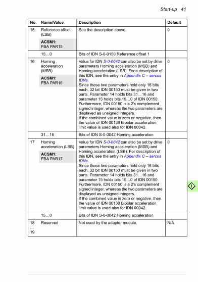
15 Reference offset (LSB)
See the description above. 0
ACSM1: FBA PAR15
15…0 Bits of IDN S-0-0150 Reference offset 1
16 Homing acceleration (MSB)
Value for IDN S-0-0042 can also be set by drive parameters Homing acceleration (MSB) and Homing acceleration (LSB). For a description of this IDN, see the entry in Appendix C – sercos IDNs.Since these two parameters hold only 16 bits each, 32 bit IDN 00150 must be given in two parts. Parameter 14 holds bits 31…16 and parameter 15 holds bits 15…0 of IDN 00150. Furthermore, IDN 00150 is a 2's complement signed integer, whereas the two parameters are displayed as unsigned integers.If the combined value is zero or negative, then the value of IDN 00138 Bipolar acceleration limit value is used also for IDN 00042.
0
ACSM1: FBA PAR16
31…16 Bits of IDN S-0-0042 Homing acceleration
17 Homing acceleration (LSB)
Value for IDN S-0-0042 can also be set by drive parameters Homing acceleration (MSB) and Homing acceleration (LSB). For description of this IDN, see the entry in Appendix C – sercos IDNs. Since these two parameters hold only 16 bits each, 32 bit IDN 00150 must be given in two parts. Parameter 14 holds bits 31…16 and parameter 15 holds bits 15…0 of IDN 00150. Furthermore, IDN 00150 is a 2's complement signed integer, whereas the two parameters are displayed as unsigned integers.If the combined value is zero or negative, then the value of IDN 00138 Bipolar acceleration limit value is used also for IDN 00042.
0
ACSM1: FBA PAR17
15…0 Bits of IDN S-0-0042 Homing acceleration
18…19
Reserved Not used by the adapter module. N/A
No. Name/Value Description Default
42 Start-up
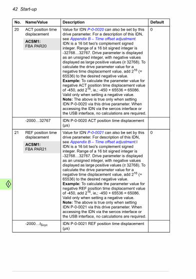
20 ACT position time displacement
Value for IDN P-0-0020 can also be set by this drive parameter. For a description of this IDN, see Appendix B – Time offset adjustment.IDN is a 16 bit two's complement signed integer. Range of a 16 bit signed integer is-32768…32767. Drive parameter is displayed as an unsigned integer, with negative values displayed as large positive values (≥ 32768). To calculate the drive parameter value for a negative time displacement value, add 216 (= 65536) to the desired negative value.Example: To calculate the parameter value for negative ACT position time displacement value of -450, add 216, ie,: -450 + 65536 = 65086. Valid only when setting a negative value.Note: The above is true only when settingIDN P-0-0020 via this drive parameter. When accessing the IDN via the sercos interface or the USB interface, no calculations are required.
0
ACSM1: FBA PAR20
-2000…32767 IDN P-0-0020 ACT position time displacement (µs)
21 REF position time displacement
Value for IDN P-0-0021 can also be set by this drive parameter. For description of this IDN, see Appendix B – Time offset adjustment.IIDN is a 16 bit two's complement signed integer. Range of a 16 bit signed integer is-32768…32767. Drive parameter is displayed as an unsigned integer, with negative values displayed as large positive values (≥ 32768). To calculate the drive parameter value for a negative time displacement value, add 216 (= 65536) to the desired negative value.Example: To calculate the parameter value for negative REF position time displacement value of -450, add 216, ie,: -450 + 65536 = 65086. Valid only when setting a negative value.Note: The above is true only when settingIDN P-0-0021 via this drive parameter. When accessing the IDN via the sercos interface or the USB interface, no calculations are required.
0
ACSM1: FBA PAR21
-2000…tScyc IDN P-0-0021 REF position time displacement (µs)
No. Name/Value Description Default

Start-up 43
22 DRIVE POS CTL MODE
Selects the ACSM1 control mode to be used in the position control operation mode. For information on ACSM1 control modes, see the ACSM1 drive documentation.Content of this parameter is also visible in IDN P-0-0022.
0
ACSM1: FBA PAR22
0 Position control
1 Synchron control
23…24
Reserved Not used by the adapter module. N/A
25 REINIT SERCOS Can be used to force the re-initialization of the sercos interface.After setting the parameter to 1, refresh drive parameters to re-initialize the sercos interface.
0
ACSM1: FBA PAR25
0 No operation
1 Re-initialize sercos interface
26 Reserved Not used by the adapter module. N/A
27 FBA PAR REFRESH
Validates any changed adapter module configuration parameter settings. After refreshing, the value reverts automatically to 0 = Done.Note: This parameter cannot be changed while the drive is running.
0 = Done
ACSM1: FBA PAR REFRESH
0 = Done Refreshing done
1 = Refresh/Configure
Refreshing
No. Name/Value Description Default

44 Start-up
28 PAR TABLE VER Read-only. Displays the parameter table revision of the fieldbus adapter module mapping file stored in the memory of the drive.
In format xyz, where x = major revision numbery = minor revision numberz = correction numberORin format axyz, where a = major revision numberxy = minor revision numbersz = correction number or letter.
N/A
ACSM1: PAR TABLE VER
0x0000…0xFFFF Parameter table revision
29 DRIVE TYPE CODE
Read-only. Displays the drive type code of the fieldbus adapter module mapping file stored in the memory of the drive.
N/A
ACSM1: DRIVE TYPE CODE
0…65535 Drive type code of the fieldbus adapter module mapping file
30 MAPPING FILE VER
Read-only. Displays the fieldbus adapter module mapping file revision stored in the memory of the drive in decimal format. Example: 0x107 = revision 1.07.
N/A
ACSM1: MAPPING FILE VER
0…65535 Mapping file revision
No. Name/Value Description Default

Start-up 45
31 D2FBA COMM STA
Read-only. Displays the status of the fieldbus adapter module communication.Note: The value names may vary by drive.
0 = Idle
ACSM1: D2FBA COMM STA
0 = Idle Adapter is not configured.
1 = Exec.init Adapter is initializing.
2 = Time out Time-out has occurred in the communication between the adapter and the drive.
3 = Conf.err Adapter configuration error: Major or minor revision code of the common program revision in the fieldbus adapter module is not the revision required by the module or mapping file upload has failed more than three times.
4 = Off-line Adapter is off-line.
5 = On-line Adapter is on-line.
6 = Reset Adapter is performing a hardware reset.
32 FBA COMM SW VER
Read-only. Displays the common program revision of the adapter module in format axyz, where:a = major revision numberxy = minor revision numbersz = correction number or letter.Example: 190A = revision 1.90A
N/A
ACSM1: FBA COMM SW VER
0x0000…0xFFFF Common program version of the adapter module
33 FBA APPL SW VER
Read-only. Displays the application program revision of the adapter module.
N/A
ACSM1: FBA COMM APPL VER
0x0000…0xFFFF Application program revision of the adapter module
1) The default value of Rotational position resolution is 0x0036EE80 = 3600000 (decimal).
No. Name/Value Description Default

46 Start-up
Control locations
ABB drives can receive control information from multiple sources including digital inputs, analog inputs, the drive control panel and a communication module (for example, the adapter module). ABB drives allow the user to separately determine the source for each type of control information (Start, Stop, Direction, Reference, Fault reset, etc.).
To give the fieldbus master station the most complete control over the drive, the communication module must be selected as the source for this information. The parameter setting examples below contain the drive control parameters needed in the examples. For a complete parameter list, see the drive documentation.
Required drive parameter configuration for ACSM1 drives
Configure the drive to make it function properly with the adapter module. The required drive parameter settings for the ACSM1 series drives are listed below. Refer to the drive documentation for more information about these parameters.
General settings
Set the following ACSM1 parameters as instructed to ensure proper operation.
No. Parameter name Set to value
10.01 EXT1 START FUNC FBA
24.01 SPEED REF1 SEL FBA REF1
32.01 TORQ REF1 SEL FBA REF1
34.01 EXT1/EXT2 SEL C.False
34.02 EXT1 MODE1/2 SEL C.False
50.01 FBA ENABLE Enable
50.04 FBA REF1 MODESEL Raw data, Torque, Speed or Position (see below)
50.05 FBA REF2 MODESEL Raw data, Torque, Speed or Position (see below)
60.05 POS UNIT Revolution
60.10 POS SPEED UNIT u/s
65.01 POS REFSOURCE Ref table

Start-up 47
Drive-controlled homing procedure parameters
If the drive-controlled homing procedure is used, set the following parameters as shown below.
Note: The adapter module sets the value of parameter 62.01 according to IDN 00147 Homing parameter.
Parameter for IDN S-0-0400 Home switch
If IDN 00400 Home switch is used by the master, the home switch digital input must be routed to the adapter module, as shown below.
Note: Despite the misleading name of parameter 50.11 FBA SW B15 SRC it selects the source for DCU SW bit 31. Bit 10 of parameter 6.11 POS CORR STATUS contains the status of the home switch digital input. The value for IDN 00400 is taken from DCU SW bit 31.
65.02 PROF SET SEL C.False
65.03 POS START 1 P.2.12 FBA MAIN CW.25
65.04 POS REF 1 SEL FBA REF1
65.22 PROF VEL REF SEL FBA REF1
67.01 SYNC REF SEL FBA REF1
70.03 POS REF ENA C.False
No. Parameter name Set to value
62.01 HOMING METHOD 3, 4, 5, 6, 17, 18, 19, 20, 21, 22, 33 or 34
62.02 HOMING START FUNC Normal
62.03 HOMING START P.2.12 FBA MAIN CW.26
No. Parameter name Set to value
50.11 FBA SW B15 SRC P.6.11 POS CORR STATUS.10
No. Parameter name Set to value

48 Start-up
Parameters for drive synchronization
Set the following parameters for the drive synchronization.
Interpolator settings
The interpolator settings are applicable in the ACSM1 synchron control mode. The position reference in this control mode can be interpolated to achieve a smoother motion response. The interpolator cycle time should be set equal to the sercos cycle time.
Default drive control mode
The drive control mode is changed by the adapter module according to the operation mode requested by the sercos master. However, we recommend you to set par. 34.03 EXT1 CTRL MODE1 according to the primary operation mode.
Note: The value of parameter 34.03 EXT1 CTRL MODE1 does not change when the adapter module switches the drive control mode.
No. Parameter name Set to value
57.09 KERNEL SYNC MODE FBsync
57.10 KERNEL SYNC OFFS -0.050 ms
51.06 FBA PAR6 3 or 4
No. Parameter name Set to value
67.03 INTERPOLAT MODE INTERPOLATE
67.04 INTERPOLAT CYCLE Set equal to sercos cycle time (ms)
No. Parameter name Set to value
34.03 EXT1 CTRL MODE1 Speed, Torque, Position or Synchron
Start-up 49
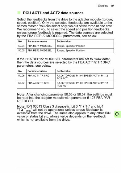
DCU ACT1 and ACT2 data sources
Select the feedbacks from the drive to the adapter module (torque, speed, position). Only the selected feedbacks are available to the sercos master. You can select only two out of the three at one time. We recommend you to select the speed and position feedbacks, unless torque feedback is required. The data sources are selected by the FBA REF1/2 MODESEL parameters, see below.
If the FBA REF1/2 MODESEL parameters are set to "Raw data", then the data sources are selected by the FBA ACT1/2 TR SRC parameters, see below.
Note: After changing parameter 50.06 or 50.07, the settings must be read into the adapter module with parameter 51.27 FBA PAR REFRESH.
Note: IDN 00013 Class 3 diagnostic, bit 3 "T ≥ Tx" and bit 4 "T ≥ Tlimit" will not be operational unless torque feedback is available from the drive. The same also applies to any other IDN value or status bit etc. whose value depends on the feedback which is not available from the drive.
No. Parameter name Set to value
50.04 FBA REF1 MODESEL Torque, Speed or Position
50.05 FBA REF2 MODESEL Torque, Speed or Position
No. Parameter name Set to value
50.06 FBA ACT1 TR SRC P.1.06 TORQUE, P.1.01 SPEED ACT or P.1.12 POS ACT
50.07 FBA ACT2 TR SRC P.1.06 TORQUE, P.1.01 SPEED ACT or P.1.12 POS ACT
50 Start-up
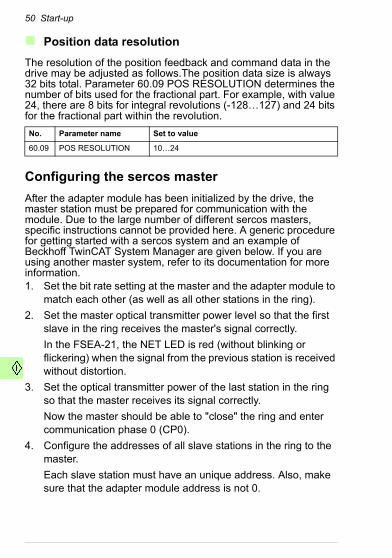
Position data resolution
The resolution of the position feedback and command data in the drive may be adjusted as follows.The position data size is always 32 bits total. Parameter 60.09 POS RESOLUTION determines the number of bits used for the fractional part. For example, with value 24, there are 8 bits for integral revolutions (-128…127) and 24 bits for the fractional part within the revolution.
Configuring the sercos master
After the adapter module has been initialized by the drive, the master station must be prepared for communication with the module. Due to the large number of different sercos masters, specific instructions cannot be provided here. A generic procedure for getting started with a sercos system and an example of Beckhoff TwinCAT System Manager are given below. If you are using another master system, refer to its documentation for more information.1. Set the bit rate setting at the master and the adapter module to
match each other (as well as all other stations in the ring).
2. Set the master optical transmitter power level so that the first slave in the ring receives the master's signal correctly.
In the FSEA-21, the NET LED is red (without blinking or flickering) when the signal from the previous station is received without distortion.
3. Set the optical transmitter power of the last station in the ring so that the master receives its signal correctly.
Now the master should be able to "close" the ring and enter communication phase 0 (CP0).
4. Configure the addresses of all slave stations in the ring to the master.
Each slave station must have an unique address. Also, make sure that the adapter module address is not 0.
No. Parameter name Set to value
60.09 POS RESOLUTION 10…24
Start-up 51
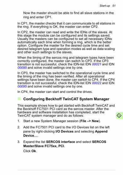
Now the master should be able to find all slave stations in the ring and enter CP1.
In CP1, the master checks that it can communicate to all stations in the ring. If everything is OK, the master can enter CP2.
In CP2, the master can read and write the IDNs of the slaves. At this stage the module can be configured and its settings saved. Usually the masters can be configured to set all necessary IDNs automatically each time when forming a ring, which is the better option. Configure the master for the desired cycle time and set desired telegram type and operation modes as well as data scaling and other such settings to the slaves.
When the timing of the sercos ring and telegram types have been correctly configured, the master can switch to CP3. If the CP3 transition is not successful, check the IDN-list IDN 00021 and IDN 00095 and solve invalid settings one by one.
In CP3, the master has switched to the operational cycle time and the timing of the ring has been verified. After all operational settings have been done, the master can switch to CP4. If the CP4 transition is not successful, check the IDN-list IDN 00022 and IDN 00095 and solve invalid settings one by one.
In CP4, the master can start and control the drives.
Configuring Beckhoff TwinCAT System Manager
This example shows how to get started with Beckhoff TwinCAT and the Beckhoff FC7501 PCI card as the sercos master. After the hardware and software installation has completed, start the TwinCAT system manager and do as follows:
1. Start a new System Manager session (File –> New).
2. Add the FC7501 PCI card to the I/O Devices list on the left pane by right-clicking I/O Devices and selecting Append Device….
3. Expand the list SERCOS interface and select SERCOS Master/Slave FC75xx, PCI.
Click Ok.

52 Start-up
4. On the new device, eg, Device 1 (FC75xx), select the FC 75xx tab and the correct bit rate for the ring in the Data Rate (MBaud) field.
It must match the bit rate set on the adapter module.
5. Select an appropriate value on the Send Power (m) field.
See the figure below.
6. Add the drive to the I/O device by right-clicking, eg, Device 1 (FC75xx) and selecting Append Box….
7. Expand the Miscellaneous list and select Drive Generic (SERCOS).
Click Ok.
8. Select the new drive, eg, Axis 1 (Sercos Drive).

Start-up 53
9. On the SERCOS Drive tab, select the correct drive address matching the address set on the adapter module.
10. Select the operation mode according to the application.
In this example, select the operation mode Position 1. See section Supported modes of operation.
11. Select the telegram type according to the application.
In this example, the telegram type is Configurable Telegram. See section Telegram types.
See the figure below.
12. On the Startup tab, click IDN S-0-0076 Position data scaling type and then Edit….
13. Set value 2 on the Value field and click Ok.
You have now selected rotational scaling, preferred scaling and absolute format for the Position data scaling type. The

54 Start-up
master will automatically make this setting when initializing the ring.
14. Change the S-0-0044 Velocity data scaling type value to 2 in the same way.
15. Verify that value 2 (0x0002) has been set to both IDN S-0-0044 and S-0-0076.
16. On the Inputs and Outputs tabs, verify that at least IDNs S-0-0051 and S-0-0047 have been selected to be transferred cyclically from the drive to the master (Inputs) and from the master to the drive (Outputs).
17. To determine the cycle time, map a variable to a task as follows:
• Add a task by expanding the SYSTEM - Configuration list on the left pane.
• Right-click Additional Tasks and select Append Task….
• Click Ok in the Insert Task dialog box.
In the TwinCAT system, a task defines the cycle time, therefore at least one variable from the Sercos Drive axis must be mapped to a task.
18. On the Task tab, tick the Auto start check box when you have selected, eg, Task 1.
Now you can adjust the cycle time with the Cycle ticks selection.
19. Select, eg, 2 ms cycle time.
20. On the left pane, right-click on Inputs under, eg, Task 1 and select Insert Variable….
21. Select Variable type INT32 and click Ok.
22. To map the task variable to, eg, Axis 1, click the Linked to… button and select Position feedback 1 value.

Start-up 55
Click Ok. See the figure below.
23. Select Activate Configuration from the Actions menu to start the sercos master.
Click Yes and Ok in the dialog boxes to restart the TwinCAT System in Run Mode.
If errors occur, IDN values to be set in startup may be incorrect or not matching the drive configuration. The IDN values of the adapter module can be monitored on the Online tab of, eg, Axis 1 (Sercos Drive) when the master is in CP2, CP3 or CP4.
The current communication phase is visible on the Online tab of, eg, Device 1 (FC75xx). In CP4, the master has control of the drive. The Status and Control words and other cyclic data can be monitored and controlled in the Actual Values and Nominal Values lists under, eg, Axis 1 (Sercos Drive).

56 Start-up

Communication profiles 57
7Communication profiles
Contents of this chapter
This chapter describes the communication profiles used in the communication between the sercos ring, the adapter module and the drive.
Communication profiles
Communication profiles are defined ways of conveying commands and status information, transported over some communication protocol, between the master station and the drive.
The adapter module provides two profile choices. The sercos profile is converted to the drive's native profile (eg, DCU) in the module, whereas in the transparent profile mode no data conversion takes place. Both profiles are transported over the sercos protocol.
58 Communication profiles
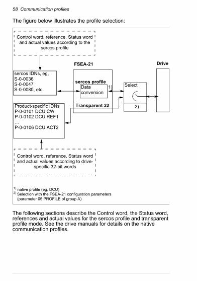
The figure below illustrates the profile selection:
The following sections describe the Control word, the Status word, references and actual values for the sercos profile and transparent profile mode. See the drive manuals for details on the native communication profiles.
Control word, reference, Status word and actual values according to the
sercos profile
sercos profileDataconversion
Transparent 32
FSEA-21 Drive
Product-specific IDNsP-0-0101 DCU CWP-0-0102 DCU REF1…P-0-0106 DCU ACT2
Control word, reference, Status word and actual values according to drive-
specific 32-bit words
sercos IDNs, eg,S-0-0036S-0-0047S-0-0080, etc. 1) Select
2)
1) native profile (eg, DCU)2) Selection with the FSEA-21 configuration parameters
(parameter 05 PROFILE of group A)

Communication profiles 59
sercos communication profile
Telegram types
The telegram types supported by the adapter module are listed in the table below with their contents. The contents of the telegrams in telegram type 7 (Application telegram) are user configurable.
# Name MDT AT
0 Standard telegram 0
- -
1 Standard telegram 1
S-0-0080 Torque command
-
2 Standard telegram 2
S-0-0036 Velocity command
S-0-0040 Velocity feedback
3 Standard telegram 3
S-0-0036 Velocity command
S-0-0051 Position feedback
4 Standard telegram 4
S-0-0047 Position command
S-0-0051 Position feedback
5 Standard telegram 5
S-0-0047 Position commandS-0-0036 Velocity command
S-0-0051 Position feedbackS-0-0040 Velocity feedback
6 Standard telegram 6
S-0-0036 Velocity command
-
7 Application telegram
S-0-0036 Velocity commandS-0-0037 Additive velocity cmd.S-0-0047 Position commandS-0-0080 Torque commandS-0-0081 Additive torque cmd.P-0-0101 DCU CWP-0-0102 DCU REF1P-0-0103 DCU REF2
S-0-0040 Velocity feedbackS-0-0051 Position feedbackS-0-0084 Torque feedbackS-0-0189 Following distanceP-0-0104 DCU SWP-0-0105 DCU ACT1P-0-0106 DCU ACT2

60 Communication profiles
The telegram type is set into IDN 00015, see description below. The master usually handles bits above bit 2 automatically, and therefore you must only specify the telegram type number 0…7 (see the table above). The telegram type must be set in CP2. When telegram type 7 is selected, contents of the telegrams must be specified in CP2 to IDN 00016 and IDN 00024.
Note: Do not write into the IDNs P-0-0101 (32869) DCU CW, P-0-0102 (32870) DCU REF1 or P-0-0103 (32871) DCU REF2 when the sercos profile is selected. You may write into them when the transparent communication profile is selected.
Supported modes of operation
The adapter module supports the following operation modes.
Note: The different operation modes are available only with specified telegram types. The telegram type must be selected according to the operation modes to be used.
Note: No distinction is made between the position control operation modes. IDN S-0-0296 Velocity feed forward gain is
IDN S-0-0015 Telegram type
Bit Meaning
15…12 Reserved
11…10 Length of the AT service channel
9…8 Length of the MDT service channel
7…3 Reserved
2…0 Telegram type (0…7)
Mode Name Telegram types
0 No mode of operation all
1 Torque control 1, 7
2 Velocity control 2, 3, 5, 6, 7
3 Position control, with following error 4, 5, 7
0xB Position control, without following error 4, 5, 7
7 Operation mode without control loops all

Communication profiles 61
operational also in operation mode “position control, with following error”.
The operation modes are configured by bits 9…0 in the IDNs listed below. These IDNs can be set in CP2 and CP3.
During operation, the operation mode (Primary operation mode, Secondary 1…3) is selected by the sercos Control word bits 11, 9, 8.
Torque control operation mode
In the torque control operation mode, the IDNs 00080 and 00081 are used to control the drive. The scaling of torque command and feedback data is determined by IDNs 00085, 00086, 00093 and 00094.
The IDN 00085 may be used to invert (change sign of) the torque command and feedback values.
IDN S-0-0032 Primary operation modeIDN S-0-0033 Secondary operation mode 1IDN S-0-0034 Secondary operation mode 2IDN S-0-0035 Secondary operation mode 3
Bit Meaning
15…10 Reserved
9…0 Operation mode
IDN S-0-0085 Torque polarity parameter
Bit Value Description
15…3 n/a Reserved
2 01
No operationInvert torque feedback value
1 01
No operationInvert additive torque command value
0 01
No operationInvert torque command value

62 Communication profiles
IDN 00086 determines the format of the torque data:• Percentage scaling means that torque command and feedback
data is expressed as percentage of the drive nominal torque with a scale of 0.1%. For example, value 123 = 12.3% torque.
• Rotational scaling means that command and feedback data is expressed as newton meters (Nm).
• Preferred (default) scaling is 10-2 Nm, eg, value 1234 = 12.34 Nm.
• When parameter scaling is selected, the scaling exponent may be changed (IDN 00094 Torque/force data scaling exponent).
The drive nominal torque value (Nm), which the module uses for rotational scaling, is visible at IDN P-0-0200 (32968) Nominal torque.
IDN S-0-0086 Torque/force data scaling type
Bit Value Meaning
15…7 0 Reserved
6 0 Data reference at the motor shaft
5 0 Reserved
4 0 Unit = Nm
3 01
Preferred scalingParameter scaling
2…0 000010
Percentage scalingRotational scaling
Communication profiles 63
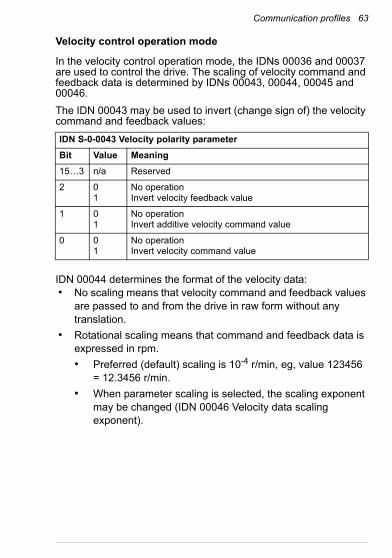
Velocity control operation mode
In the velocity control operation mode, the IDNs 00036 and 00037 are used to control the drive. The scaling of velocity command and feedback data is determined by IDNs 00043, 00044, 00045 and 00046.
The IDN 00043 may be used to invert (change sign of) the velocity command and feedback values:
IDN 00044 determines the format of the velocity data:• No scaling means that velocity command and feedback values
are passed to and from the drive in raw form without any translation.
• Rotational scaling means that command and feedback data is expressed in rpm.
• Preferred (default) scaling is 10-4 r/min, eg, value 123456 = 12.3456 r/min.
• When parameter scaling is selected, the scaling exponent may be changed (IDN 00046 Velocity data scaling exponent).
IDN S-0-0043 Velocity polarity parameter
Bit Value Meaning
15…3 n/a Reserved
2 01
No operationInvert velocity feedback value
1 01
No operationInvert additive velocity command value
0 01
No operationInvert velocity command value
64 Communication profiles
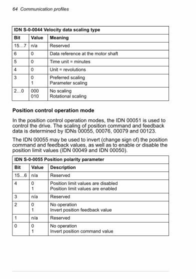
Position control operation mode
In the position control operation modes, the IDN 00051 is used to control the drive. The scaling of position command and feedback data is determined by IDNs 00055, 00076, 00079 and 00123.
The IDN 00055 may be used to invert (change sign of) the position command and feedback values, as well as to enable or disable the position limit values (IDN 00049 and IDN 00050).
IDN S-0-0044 Velocity data scaling type
Bit Value Meaning
15…7 n/a Reserved
6 0 Data reference at the motor shaft
5 0 Time unit = minutes
4 0 Unit = revolutions
3 01
Preferred scalingParameter scaling
2…0 000010
No scalingRotational scaling
IDN S-0-0055 Position polarity parameter
Bit Value Description
15…6 n/a Reserved
4 01
Position limit values are disabledPosition limit values are enabled
3 n/a Reserved
2 01
No operationInvert position feedback value
1 n/a Reserved
0 01
No operationInvert position command value

Communication profiles 65
IDN 00076 determines the format of the position data:• No scaling means that position command and feedback values
are passed to and from the drive in raw form without any translation.
• Linear scaling means that the number of position units per one axis revolution (pu/rev) is determined by the IDN 00123 Feed constant.
• Rotational scaling means that the number of position units per one axis revolution (pu/rev) is determined by the IDN 00079 Rotational position resolution.
• When preferred scaling is selected, the scaling is as follows:
• With linear scaling: 100000 pu/rev (eg, position data value 50000 = 0.5 rev. axis position).
• With rotational scaling: 3600000 pu/rev (eg, position data value 1800000 = 180 degrees).
• When parameter scaling is selected, the scaling may be changed by writing IDN 00123 (linear scaling) or IDN 00079 (rotational scaling).
• If data reference at the motor shaft is selected, the load gear ratio is set to 1 automatically (IDN 00121, IDN 00122). When data reference at the load is selected, the load gear ratio may be modified.
• Absolute format means that the drive position axis mode is set to a linear mode, which means that the position data range is continuous over multiple axis turns.
• Modulo format means that the drive position axis mode is set to a rollover mode, which means that the position data ranges only within one axis revolution, in other words, after full revolution the position data starts again from zero.
Note: When modulo format is selected, the IDN 00103 Modulo value must match the used position data scaling value, in other words, either IDN 00079 (with rotational scaling) or IDN 00123 (with linear scaling). If IDN 00103 Modulo value is left to the default value 0, the modulo value is automatically set correctly according to the selected scaling mode. The limitation stems from the fact

66 Communication profiles
that it is not possible to arbitrarily select the modulo value in the drive.
Note: IDN 00077 Linear position data scaling factor and IDN 00078 Linear position data scaling exponent do not take part in the scaling calculations. Linear position scaling is determined only by IDN 00123 Feed constant (pu/rev).
Note: Since the speed feed forward gain parameter in the drive can be set and it is effective regardless of the sercos operation mode, no functional distinction is made between the two supported position control operation modes ("with following error" and "without following error"). In other words, IDN S-0-0296 Velocity feed forward gain is operational also in operation mode “position control, with following error”. If zero feed forward is desired, set the IDN 00296 value to 0.
Homing procedure
The purpose of the homing procedure is to calibrate the position feedback value with respect to the machine zero point. The homing procedure may employ a home switch to point the home position and the home position may be referred to the encoder index pulse (zero pulse). These are configured by IDN 00147, see description below.
IDN S-0-0076 Position data scaling type
Bit Value Meaning
15…8 0 Reserved
7 01
Absolute formatModulo format (see IDN 00103)
6 01
Data reference at the motor shaftData reference at the load
5 0 Reserved
4 0 Linear scaling: unit meter (m)Rotational scaling: unit degrees
3 01
Preferred scalingParameter scaling
2…0 000001010
No scalingLinear scaling (see IDN 00123)Rotational scaling

Communication profiles 67
The homing procedure is started by setting and enabling the IDN 00148 Drive controlled homing procedure command. The drive must be enabled before executing the procedure command, and must remain enabled for the duration of the homing procedure. The drive ignores command values after the procedure command has been executed until the master cancels the procedure command (by setting IDN 00148 value back to zero).
After the homing procedure is completed successfully, IDN 00403 Position feedback value status is set to 1, which means that the position data is being referred to the machine zero point. IDN 00403 value is reset back to 0 by the IDN 00191 Cancel reference point procedure command, which also aborts the homing procedure.
S-0-0147 Homing parameter
Bit Value Meaning
15…9 n/a Reserved
8 1 Drive-controlled homing, homing distance is not selected
7 0 Drive is positioned at an arbitrary position after a homing procedure
6 0 Marker pulse is evaluated
1 Marker pulse is not evaluated
5 0 Home switch is evaluated
1 Home switch is not evaluated
4 n/a Reserved
3 0 Homing using motor feedback
2 1 Home switch connected to the drive
1 0 First marker pulse after the positive edge of the home switch
1 First marker pulse after the negative edge of the home switch
0 0 Homing direction positive
1 Homing direction negative

68 Communication profiles
The machine zero point is defined in the figure below. IDN 00150 Reference offset 1 is used to set the distance from the home position to the reference point and IDN 00052 Reference distance 1 is used to set the distance from the machine zero point to the reference point:
machine zero point + IDN 00052 - IDN 00150 = home position.
In the figure, the drive moves from left to right. and the homing is configured to stop after the first index marker pulse after the negative edge (falling edge) of the home switch.
IDN 00041 Homing velocity is used as the drive velocity reference during the homing procedure (scaling according to velocity data scaling described above). Drive acceleration is limited by IDN 00042 Homing acceleration. However, if IDN 00138 Bipolar acceleration limit value is less than IDN 00042 value, then it limits the acceleration also during the homing procedure. Scaling of acceleration data is described below.
Reference offset 1(IDN 00150)
Reference distance 1(IDN 00052)
Reference point
Machine zero point
Drive position
0
1
Reference marker pulse
Drive velocity
Position feedbackmarker pulse
Home switchsignal

Communication profiles 69
Note: During the homing procedure, the drive does not follow torque, velocity or position commands.
Acceleration data scaling
The scaling of acceleration data, ie, IDN 00042 and IDN 00138, is configured by IDN 00160:• No scaling means that acceleration data values are passed to
and from the drive in raw form without any translation.
• Rotational scaling means that acceleration data is expressed in rad/s2.
• Preferred (default) scaling is 10-3 rad/s2, for example, value 3142 = 3.142 rad/s2.
• When parameter scaling is selected, the scaling exponent may be changed (IDN 00162 Acceleration data scaling exponent).
S-0-0160 Acceleration data scaling type
Bit Value Meaning
15…7 0 Reserved
6 0 Data reference at the motor shaft
5 0 Time unit = second
4 0 Rotational scaling unit = radian
3 01
Preferred scalingParameter scaling
2…0 000010
No scalingRotational scaling

70 Communication profiles
Control word and Status word
The Control word is the principal means for controlling the drive from the master system. The adapter module receives the sercos Control word, controls the drive accordingly and translates status information from the drive into the sercos Status word which it sends back to the master. Contents of the sercos Control word are described in the table below. The length of the Control word is 16 bits.
Note: Bit 15 is effective only if bit 14 is '1'. Bit 13 is effective only if bits 15…14 are '11'.
Note: The primary operation mode and secondary operation modes are configured by IDN 00032, 00033, 00034 and 00035.
Note: The sercos Control word does not control drive operation if a transparent profile is selected.
Warning! In the torque control mode, bit 13 (Halt) causes only the torque reference to be set to zero, not a drive stop.
MDT Control word
Bit Name Description
15 Drive ON/OFF 0 = Drive OFF - drive is decelerated to stop, power stage remains active for the duration of delay time IDN 00207.1 = Drive ON - drive follows command values after delay time IDN 00206.
14 Enable drive 0 = Not enabled - disable power stage, torque is released immediately.1 = Enable drive - power stage enable.
13 Halt / Restart 0 = Halt drive - decelerate to stop.1 = Restart drive - run drive.
12 Reserved -
11 Operation mode Used in conjunction with bits 9 and 8.
10 IPOSYNC Master toggles this bit every control unit cycle.

Communication profiles 71
The contents of the sercos Status word are described in the table below. The length of the Status word is 16 bits.
98
Operation mode Bits 11, 9, 8 together:000 = Primary operation mode001 = Secondary operation mode 1010 = Secondary operation mode 2011 = Secondary operation mode 3
7 Real-time control bit 2
Destination of this bit is selected by IDN 00303 and IDN 00414.
6 Real-time control bit 1
Destination of this bit is selected by IDN 00301 and IDN 00413.
543
Data block element
Operation data element number of an IDN being accessed via the service channel.
2 Service channel control
0 = Transmission in progress1 = Last transmission
1 Read / Write 0 = Read service INFO1 = Write service INFO
0 MHS Service transport handshake of the master.
AT Status word
Bit Name Description
1514
Ready to operate 00 = Drive not ready for main power on01 = Drive logic ready for main power on10 = Torque free (power stage disabled)11 = Power stage enabled
13 Drive shut down error
0 = No error1 = Drive is shut down due to C1D error
12 C2D change 0 = No change in C2D1 = Bit toggled in C2D
11 C3D change 0 = No change in C3D1 = Bit toggled in C3D
MDT Control word
Bit Name Description

72 Communication profiles
Real time bits
The real-time status bits of the sercos Status word and real-time control bits of the sercos Control word (bits 7 and 6 of the Status and Control words) allow two bits of information to be carried within the Control and Status words to and from user selectable IDNs in the module. The destinations and sources for these bits are configured by the following IDNs:• S-0-0301 Allocation of real-time control bit 1
• S-0-0413 Bit number allocation of real-time control bit 1
• S-0-0303 Allocation of real-time control bit 2
• S-0-0414 Bit number allocation of real-time control bit 2
1098
Actual operation mode
000 = Primary operation mode001 = Secondary operation mode 1010 = Secondary operation mode 2011 = Secondary operation mode 3
7 Real-time status bit 2
Source of this bit is selected by IDN 00307 and IDN 00416.
6 Real-time status bit 1
Source of this bit is selected by IDN 00305 and IDN 00415.
5 Procedure command change
0 = No change in procedure command acknowledgement1 = Changing procedure command acknowledgement
4 Reserved -
3 Status command value processing
0 = Command values ignored1 = Drive follows command values
2 Service channel error
0 = No error1 = Service channel error
1 Busy Service channel status:0 = Step finished, ready for new step1 = Step in progress
0 AHS Service channel handshake of the drive
AT Status word
Bit Name Description

Communication profiles 73
• S-0-0305 Allocation of real-time status bit 1
• S-0-0415 Bit number allocation of real-time status bit 1
• S-0-0307 Allocation of real-time status bit 2
• S-0-0416 Bit number allocation of real-time status bit 2
The only IDN which should be allocated to real-time control bit 1 and 2 is IDN P-0-0101 DCU CW (IDN 32869). Other IDNs have no function. In the DCU CW of the ACSM1 drive, there are four freely configurable bits for the user application, bits 31…28. When assigning DCU CW bits other than the freely configurable bits, make sure that you do not modify any bit used by the sercos profile. The DCU CW bits 31…28 can be used in the drive for example to control digital outputs etc.
Any IDN can be allocated to real-time status bits. One possible use for the real-time status bits would be to route the DCU SW bits 31…28 to the sercos Status word. For example, digital inputs of the drive can be used by the master in this way.
Note: IDN 00400 Home switch value is always taken from DCU SW bit 31. If IDN 00400 is used by the master, the drive must be configured so that the home switch status is routed to DCU SW bit 31. When IDN 00400 is not used, then DCU SW bit 31 may be used for other purposes, but IDN 00400 will display the value of DCU SW bit 31 in any case.

74 Communication profiles
Transparent communication profile
With the transparent profile, the drive can be controlled directly by its native Control and Status words. The drive Control and Status words (DCU CW and DCU SW) and its raw command values ("reference", REF1 and REF2) and feedback values ("actual", ACT1 and ACT2) are available for the master in IDNs P-0-0101 (32869) … P-0-0106 (32874). See the drive documentation on details of the drive's Control and Status words.
To control the drive via cyclic sercos communication in the transparent profile mode, use the configurable telegram ("application telegram") and map the above mentioned IDNs to the MDT and AT telegrams. The settings are described in the table below.
Note: Only one reference value (REF1 or REF2) is required to control the drive, therefore, for example, REF2 may be omitted. The same applies to the actual values.
In the transparent profile mode the sercos Control word does not control drive operation. Likewise, the sercos Status word should be ignored in the transparent profile mode.
IDN Value Description
00015 Telegram type 7 Configurable telegram
00016 Configuration list of AT 32872 P-0-0104 DCU SW
32873 P-0-0105 DCU ACT1
32874 P-0-0106 DCU ACT2
00024 Configuration list of MDT 32869 P-0-0101 DCU CW
32870 P-0-0102 DCU REF1
32871 P-0-0103 DCU REF2

Communication protocol 75
8Communication protocol
Contents of this chapter
This chapter describes the communication on an sercos ring and explains fundamental sercos concepts.
Overview of communication
The sercos interface uses optical fiber as the physical data transfer media. The topology of the network is ring and a sercos network is often called a sercos ring. The line coding is NRZI (non-return-to-zero, inverted) with zero bit stuffing after five consecutive ones to maintain receiver synchronization. A fill signal is transmitted when telegrams are not sent to maintain receiver synchronization. Each slave acts as a regenerator and transmits its own telegrams only when requested by the master or automatically at times specified by the master.
There is one master station and up to 254 slave nodes in the ring. One physical slave station may contain multiple slave nodes. Each slave node has a unique address (1…254). Address 0 means that the slave must act only as a passive regenerator. Address 255 is the broadcast address.

76 Communication protocol
Frame structure
Every telegram starts and ends with delimiter 01111110. The delimiter denoting the beginning of a frame is followed by an 8-bit address field. 0 represents a no-station address and 255 is the broadcast address (all-station address).
After the address field, there is a data section with varying length, a frame check sequence (FCS) and a delimiter denoting the end of a frame.
Telegrams
There are three types of telegrams: master synchronization telegram (MST), master data telegram (MDT), and amplifier telegram (AT).
MST
Master synchronization telegram (MST) is transmitted by the master as a broadcast telegram at fixed, predefined intervals. The MST is used to define the network synchronization cycle ("sercos cycle") which keeps the slave devices synchronized with the master and each other. The start of each cycle is defined to be the end of the MST.
MDT
Master data telegram (MDT) is transmitted by the master as a broadcast telegram once every network cycle, at a specified time (t2) after the end of the last MST. The MDT contains the cyclic command data for each slave. Each slave has its own specified data slot within the MDT.
AT
Amplifier telegram (AT), also called drive telegram, is transmitted by the slave at a specified time (t1) after the end of the last MST. Each slave is assigned a different t1 by the master. The AT contains the cyclic status and feedback data from the slave.

Communication protocol 77
Service channel
Non-cyclic data transfer (the sercos "service channel") is initiated and controlled by the master. A slave cannot start a service channel transfer, it can only respond. The service channel is transported within the normal cyclic traffic; there are data slots reserved in the MDT and the AT for the service channel.
IDNs
The master controls the slaves by reading and writing a predefined set of data objects, called IDNs ("identification numbers"). The IDNs can be read and written by the cyclic transmissions or by the non-cyclic service channel.
sercos cycle and time parameters
The figure below depicts one network cycle in communication phase CP3 or CP4. An MST signifies the start of the cycle, the cycle time (tScyc) is the time between two MSTs. Time instant zero being the end of the MST. In this example, there are five slaves in the ring, with addresses 1…5, and thus there are five ATs (AT1…AT5). The address of the slave in question is 4. Thus the t1 for this slave is the starting time of AT4. Each slave has a unique t1, assigned by the master. MDT starts at time t2. Time t3 is called "command value valid time" and this is the time at which the drive may access the command values sent by the master in the MDT. Time t4 is called "feedback acquisition capture point" and it is the time at which the slave should sample its feedback, for example, encoder position.
Note: t2, t3 and t4 need not occur in numerical order - the master may place them in any order (for example, t3 and t4 may occur before t2 in the cycle).
MST AT1 AT2 AT3 AT4 AT5 MDT MST
t1 t4
t5
t3t2
tMTSY
tMTSG

78 Communication protocol
The slave has multiple IDNs which contain minimum timing requirements for that slave. The master reads these IDNs from each slave and decides the cycle timing for the whole network according to these time parameters, described below. Some of these are also visible in the figure above.
Procedure commands
Procedure commands are IDNs which cause the slave to execute a complex process which may take a long time to complete (significantly longer than one cycle time). Procedure commands are set, enabled, interrupted and cancelled by the master by writing the corresponding IDN. Procedure commands may succeed to be correctly executed or fail to execute correctly. Examples of procedure commands are, for example, IDN 00148 Drive controlled homing procedure command and IDN 00099 Reset class 1 diagnostic, etc.
Timing IDN Function
t1min 00003 The minimum time at which the slave can send its AT.
tMTSG 00090 The minimum time requirement between the end of the MDT and t3.
tMTSY 00088 The minimum time requirement between the end of the MDT and start of the next MST.
t5 00005 The minimum time requirement between t4 and the end of the next MST.
tATMT 00004 The minimum time requirement between the end of the slave's AT and t2.
tATAT 00087 The minimum time requirement between two ATs sent by the same slave station during single network cycle. This applies only for slaves with multiple logical slave nodes in the same physical slave station. The adapter module controls only one drive and thus it has only one slave node.

Communication protocol 79
Communication phases
When the sercos ring is in operation, it is in one the defined states, called communication phases (CP). There are five communication phases, CP0…CP4. The master selects the communication phase. When a communication phase is successfully completed, the master may move on and switch to a higher communication phase.
Communication phase 0 (CP0)
The master transmits MSTs and the slaves simply repeat them around the ring, back to the master. This allows the master to establish that the ring is intact. When the master receives back its own transmission correctly, it can switch to CP1.
Communication phase 1 (CP1)
The master interrogates each slave at a time using the address of each slave. This allows the master to establish that all the slaves are present in the ring. If the master can raise all the slaves that should be present in the ring, it can switch to CP2.
Communication phase 2 (CP2)
In CP2 the master can read and write IDNs of the slaves. In this phase the master reads timing requirements from each slave and writes the network timing and telegram configuration to each slave. After these configurations, the master requests each slave to perform the CP3 transition check (IDN 00127) to check the settings. If the checks are completed without errors, the master can switch to CP3.
Communication phase 3 (CP3)
When entering CP3 the cycle time is switched to the operational cycle time, eg, 1 ms or 500 µs. Also the AT and MDT telegrams are now configured for cyclic operation. In this phase the master usually writes any remaining required settings to each slave. After all slaves have been configured for operation, the master requests each slave to perform the CP4 transition check (IDN 00128) to check that the slave is ready for operation. If the checks are completed without errors, the master can switch to CP4.

80 Communication protocol
Communication phase 4 (CP4)
CP4 is the normal operational state, where the drive is allowed to run.

Diagnostics 81
9Diagnostics
Contents of this chapter
This chapter explains how to trace faults with the status LEDs on the adapter module and diagnostic sercos IDNs.
Fault and warning messages
See the firmware manual for fault and warning messages.
LEDs
The adapter module is equipped with three diagnostic LEDs. The LEDs are described below.
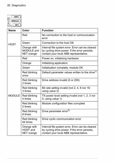
82 Diagnostics
Name Color Function
HOST
Red No connection to the host or communication error
Green Connection to the host OK
Orange with MODULE and NET orange
Internal file system error. Error can be cleared by cycling drive power. If the error persists, contact your local ABB representative.
MODULE
Red Power on, initializing hardware
Orange Initializing application
Green Initialization complete, module OK
Red blinking once
Default parameter values written to the drive1)
Red blinking2 times
Drive address invalid (0 or 255)
Red blinking3 times
Bit rate setting invalid (not 2, 4, 8 nor 16; using value 2)
Red blinking4 times
TX power level setting invalid (not 1, 2, 3 nor 4; using value 1)
Red blinking5 times
Module configuration files corrupted
Red blinking8 times
Drive parameter error2)
Red blinking64 times
Drive cyclic communication error
Orange with HOST and NET orange
Internal file system error. Error can be cleared by cycling drive power. If the error persists, contact your local ABB representative.

Diagnostics 83
Certain error states are reported by the MODULE LED blinking in red color. The number of flashes followed by a pause indicates the cause of the error, as described in the table above. The same error code is visible in IDN 00390 Diagnostic number as a decimal value (eg, 3 red flashes: value = 3).
NET
Off (dark) sercos interface not initialized
Red blinking fast
No signal detected (FIBBR indication)
Red flickering Received signal distorted (RDIST indication). Adjust transmit power level of the previous slave. Check fiber condition.
Red CP0
Orange CP1 or CP2
Blinking green CP3
Green CP41) The module writes default values to the drive when it is connected to the drive for the first time. See FSEA-21 configuration parameters – group A (group 1).2) The drive parameter error means that there is error in drive parameters or other data received from the drive or that reading or writing drive data has failed.
Name Color Function

84 Diagnostics
Diagnostic IDNs
The diagnostic IDNs in the sercos interface that provide error information about the slave are described below.
Class 1 diagnostic (IDN 00011)
IDN S-0-00011 Class 1 diagnostic bits are described below. Any class 1 error causes drive shut down.
Class 1 diagnostic bits are reset by the procedure command IDN 00099 (PC99).
Note: All MODULE LED / IDN 00390 error codes are always reset by PC99.
Note: PC99 overwrites the diagnostic message IDN 00095.
IDN S-0-0011 Class 1 diagnostic
Bit Meaning
15 Manufacturer-specific error (see IDN 00129)
14 Reserved
13 Position limit exceeded1) (see IDNs 00049, 00050)
12 Communication error (see IDN 00014)
11 Excessive position deviation2) (see IDN 00159)
10 Power supply phase error
9 Undervoltage
8 Overvoltage
7 Overcurrent
6 Reserved
5 Feedback loss
4 Reserved

Diagnostics 85
Manufacturer class 1 diagnostic (IDN 00129)
IDN 00129 Manufacturer class 1 diagnostic is an extension of the Class 1 diagnostic. Its bits are described below. Any class 1 error causes drive shut down.
Manufacturer class 1 diagnostic bits are reset by the procedure command IDN 00099 (PC99). However, there are the following exceptions due to safety concerns:
Bit 15 is reset in CP0 and in CP4 transition check.
3 Cooling system failure
2 Motor overtemperature
1 Amplifier overtemperature
0 Reserved1) Position limits are active only when in the position control operation mode and the limits are enabled (see IDN 00055) and when position data is being referred to the machine zero point (see IDN 00403).2) Position window is active only when in the position control operation mode.
IDN S-0-0129 Manufacturer class 1 diagnostic
Bit Meaning
15 Error in CP4 transition check while the Ignore errors mode has been selected (see Drive configuration)
14 Error during initialization
13 Connection to the drive has failed
12 Failed to read fault code from the drive
11, 10 Reserved
9 Drive parameter error
8 Configuration files corrupted
7…2 Reserved
1 Unsupported drive type
0 Drive fault. See IDN P-0-0100 (32868).
IDN S-0-0011 Class 1 diagnostic
Bit Meaning

86 Diagnostics
Bit 14 is reset by re-initialization of the sercos interface.
Bit 9 is reset only when drive parameters are processed after re-initialization of the sercos interface or after parameter refresh.
When bit 14 Error during initialization is asserted, the corresponding diagnostic message (see IDN 00095) is probably already overwritten by PC99 and PC127 results caused by the master executing these procedure commands. In this case the diagnostic message on the error, which causes bit 14 to be asserted, can be read in CP2 by phasing the ring back to CP0 and then to CP2.
Bit 9 Drive parameter error means that there is an error in drive parameters or other data received from the drive or that reading or writing drive data has failed.
Interface status (IDN 00014)
IDN 00014 Interface status contains status and error information on the sercos interface. During normal operation bits 2…0 indicate the current communication phase. All bits are described below.
IDN S-0-0014 Interface status
Bit Meaning
15…12 Reserved
11 IPO-SYNC error
10 Drives with the same address in the ring
9 Switching to the uninitialized operation mode
8 Phase switching without ready acknowledgement
7 Error during phase downshift (not to phase 0)
6 Error during phase upshift (invalid sequence)
5 Invalid phase (phase > 4)
4 MDT failure
3 MST failure
2…0 Communication phase

Diagnostics 87
Diagnostic message (IDN 00095)
IDN 00095 Diagnostic message contains a plain text status or error message from the slave. The message is posted about procedure command results and numerous error situations, etc. It is recommended to read this IDN first when encountering problems during use.
Diagnostic number (IDN 00390)
IDN 00390 Diagnostic number contains the same information as the MODULE LED when it is flashing in red color. See LEDs.
Status IDNs
The following IDNs contain status information other than error information.
Class 2 diagnostic (IDN 00012)
IDN 00012 Class 2 diagnostic contains drive warning flags. There are no active warning flags in the adapter module.
Class 3 diagnostic (IDN 00013)
IDN 00013 Class 3 diagnostic contains multiple drive status flags. When any bit in IDN 00013 is changed, the C3D change bit of the sercos Status word is set (bit 11). The Status word bit is negated when IDN 00013 is read by the master. The effect of IDN 00013 changes to the C3D change bit can be masked by IDN 00098.
The status bits are described below. When the condition is true, the corresponding bit is '1'. Each status flag is functional only if the feedback information it requires is available from the drive to the adapter module. The same status information is also available in IDNs 00330…00336.
IDN S-0-0012 Class 2 diagnostic
Bit Meaning
15…0 Reserved

88 Diagnostics
The following IDNs affect the operation of the status flags:• 00057 Position window
• 00091 Bipolar velocity limit value
• 00092 Bipolar torque limit value
• 00098 Mask class 3 diagnostic
• 00124 Standstill window
• 00125 Velocity threshold (nx)
• 00126 Torque threshold (Tx)
• 00157 Velocity window
IDN S-0-0013 Class 3 diagnostic
Bit Description Notes
15…7 Reserved
6 In position Operational in position control operation modes. See IDN 00336.
5 |ncommand| > |nlimit| Operational in the velocity control operation mode. See IDN 00335.
4 |T| ≥ |Tlimit| Operational when torque feedback available. See IDN 00334.
3 |T| ≥ |Tx| Operational when torque feedback available. See IDN 00333.
2 |nfeedback| < |nx| Operational when velocity feedback available. See IDN 00332.
1 nfeedback = 0 Operational when velocity feedback available. See IDN 00331.
0 nfeedback = ncommand Operational in the velocity control operation mode. See IDN 00330.

Technical data 89
10Technical data
Contents of this chapter
This chapter contains the technical data of the adapter module and the sercos link.

90 Technical data
FSEA-21
The following figure describes the enclosure of the adapter module from the front and side.
Installation Into the option slot on the drive
Degree of protection IP20
Package Antistatic air bubble sheet (PE)
Ambient conditions The applicable ambient conditions specified for the drive in its manuals are in effect.
Indicators Three LEDs: HOST, MODULE and NET
Connectors 20-pin connector to the drive (X2)Optical transmitter for the sercos ring, F-SMA (V1)USB Mini-B type 5-pin connector (X1)Optical receiver for the sercos ring, F-SMA (V2)
Power supply +3.3 V +5% max. 500 mA (supplied by the drive)

Technical data 91
sercos link
Compatibility The adapter module is compatible with:• USB 2.0 Full speed specification,
UHCI/OHCI/EHCI host controller• USB-IF Test-ID (TID) 40000133• FTDI Virtual COM Port (VCP) drivers for
Windows (XP, Vista, 7 and 8).
General Complies with EMC standard EN 61800-3:2004USB connection functionally isolated from the drivePrinted circuit board conformal coated
Compatible devices All sercos-compliant devices (IEC 61491)• Compliance class C (including A and B)
Medium Plastic (1 mm) or glass (0.23 mm) optical fibersercos specifications for plastic optical fibers (POF) and hard clad silica glass (HCS) optical fibers:
Connectors F-SMA (IEC 60874-2) connector, quality level 5 or better, metallic connector ring
Topology Ring
Transfer rate 2, 4 or 8 Mbit/s
Cycle times 500 µs to 65 ms in 500 µs steps
Protocol sercos
Aspect POF HCS
Core diameter
980 microns 200 microns
Cladding diameter
1000 microns 230 microns
Numeric aperture
0.47 0.37
Bandwidth > 5 MHz * 1 km > 10 MHz * 1 km

92 Technical data

Appendix A – USB interface 93
11Appendix A – USB interface
Contents of this chapter
This chapter contains instructions on how to read and write the sercos IDNs of the adapter module directly with the DriveStudio PC tool software in installations where sercos IDNs cannot be accessed through the sercos master.
Overview
Normally the sercos IDNs used for configuring the adapter module are accessed from the sercos master via the sercos interface, see section IDNs. For installations where the sercos master does not support user access to the sercos IDNs, the adapter module is equipped with an USB interface which allows access to the IDN database of the adapter module with the DriveStudio PC tool.

94 Appendix A – USB interface
Connecting the USB cable
When you connect a USB cable from the PC to the adapter module for the first time, install the FTDI virtual COM port driver into your computer to allow it to communicate with the adapter module.
Follow the instructions on the FTDI website (www.ftdichip.com) to install the drivers.
You do not need to power the drive up when you install the drivers to the PC because the USB bus is powered by the PC. However, you must switch the power on before you start DriveStudio.
Use the latest VCP (virtual COM port) drivers that support the operating system of your computer. The correct device type for the adapter module is FT232R.
To use the USB interface, connect the PC with DriveStudio to the adapter module with a USB cable as follows:
1. Make sure that the adapter module is mechanically and electrically properly installed on the drive.
2. Connect the USB cable to the X1 connector of the adapter module.
The X1 connector is a 5-pin USB Mini-B type connector.
3. Start the DriveStudio PC tool.

Appendix A – USB interface 95
Accessing the IDN database
When you have completed the installation, DriveStudio should be able to find the adapter module automatically. If the adapter module is not found:• Check cabling.
• Check the FTDI driver installation.
• Make sure no other application is reserving the COM port of the adapter module.
All IDNs of the adapter module are in parameter group 1. The parameter name consists of a long-form IDN number (such as S-0-0011) and first few letters of the IDN name. The entire name is not displayed as DriveStudio displays only max. 16-character long parameter names as shown in figure below. Refer to chapter Appendix C – sercos IDNs for a detailed description of each IDN.

96 Appendix A – USB interface
Only simple IDNs with data length of 2 or 4 bytes can be accessed with DriveStudio. Lists or strings cannot be read or written.
After configuring the module, remember to save the IDNs by using the IDN 00264 Backup working memory procedure command. The procedure command may be executed by writing value 3 to the IDN. Set the value back to 0 after use.
WARNING! The USB interface is intended only for off-line configuration of the adapter module. Do not write module IDNs via the USB interface when the sercos interface is in
operation.

Appendix B – Time offset adjustment 97
12Appendix B – Time offset adjustment
Contents of this chapter
This chapter contains information on the time offset adjustment feature of the adapter module.
Overview of time offset adjustment
In applications where there are multiple axes which are precisely synchronized to one another, it is vital that every axis drive produces the same positioning result at the same time as every other drive in the ring.
sercos specifies when the command values should be taken into use (t3) and when encoder feedback values should be sampled from the encoder (t4). However, different drive manufacturers have had different interpretations on what exactly is meant by these timing specifications. Some manufacturers may have even ignored these and take command values into use in the drives whenever they like. Furthermore, the actual control performance from command value valid time to actual axis movement varies between different drive types.
If all drives running the synchronized axes are of the same exact type, there are no problems as all drives have identical internal timing performance. However, in retrofit situations where one drive in the ring is replaced with a new, different drive, problems may arise: An increasing position difference between the different drive

98 Appendix B – Time offset adjustment
types can be seen as axis rotation speed increases. This is caused by different internal time delays in the different drive types.
The adapter module provides facilities to adjust the internal time delays for position control applications where the axis rotates:• in one direction only
• at a relatively constant speed (ie, speed changes are slow when compared to the network cycle time).
One such application would be, for example, a printing press. In the figure below, the axis rotates continuously in one direction and the position data wraps around at one full revolution in this example. The axis has reached the operational speed.
In the FSEA-21 it is possible to specify a time offset for the position command value from the adapter module to the drive ("reference value") and for the position feedback value from the drive to the adapter module ("actual value"). A delay can be inserted or alternatively a "negative delay" can also be specified, where the adapter module, in a way, predicts the future by extrapolating a new position value from the previous values. The resolution of the time offsets is one microsecond. In this way the internal performance of the FSEA-21/ACSM1 combination can be matched with that of other types of drives in the same ring and thus it becomes possible to replace old discontinued drives with new ACSM1 drives one by one as the need arises.
Time offset adjustment is only possible in position control operation modes and with rotational scaling selected in IDN 00076 (see Position control operation mode).
1
0Time
Continuousaxis rotation
Axis position(rev)
Position increases monotonously with wrap around at one axis revolution. Axis speed is practically constant.

Appendix B – Time offset adjustment 99
Reference value time offset
The time offset for position reference value (command) is adjusted by IDN P-0-0021 (32789) REF position time displacement. The adjustment range is −2000 µs … tScyc (µs), where tScyc means the sercos cycle time. A positive value means delay, a negative value means prediction for a future position. A zero value means that the reference value time offset system is disabled. If there are no access to the sercos master, the IDN P-0-0021 value can also be set via drive parameters (see Drive configuration).
Actual value time offset
The time offset for actual position value (feedback) is adjusted by IDN P-0-0020 (32788) ACT position time displacement. The adjustment range is −2000 µs … 32767 µs. A positive value means delay, a negative value means prediction for a future position. A zero value means that the actual value time offset system is disabled. If there are no access to the sercos master, the IDN P-0-0020 value can also be set via drive parameters (see Drive configuration).
Combined effects
When adjusting the REF position time displacement value, the adapter module automatically compensates its effect on the actual position value. Thus you can adjust the two time offset values independently. This compensation, however, places restrictions on the time offset calculation. The combined ACT value time offset, which is calculated as shown below, must be equal to or greater than −2000 µs.
Combined ACT time offset = ACT position time displacement − REF position time displacement.
Otherwise the adapter module will not be able to fulfill the specified time offset requirement (the combined ACT time offset will saturate to -2000 µs and the effect of REF position time offset will start to show in the feedback value).
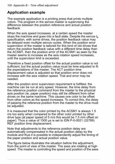
100 Appendix B – Time offset adjustment
Application example
The example application is a printing press that prints multiple colors. The program in the sercos master is supervising the difference between the position reference and actual position feedback.
When the axis speed increases, at a certain speed the master stops the machine and goes into a fault state. Despite the sercos t4 specification, with some drives, the position feedback value may be delayed even multiple sercos cycles. When the position error supervision of the master is tailored for this kind of old drives that return the position feedback value with a different time delay than the ACSM1, then the position error of the ACSM1 as seen by the master seems to increase as the axis rotation speed increases, until the supervision limit is exceeded.
Therefore a fixed position offset for the actual position value is not sufficient, but the actual position value must be time-adjusted to fit the expectations of the master. The ACT position time displacement value is adjusted so that position error does not increase with the axis rotation speed. Trial and error may be needed.
After the position error supervision requirement is fulfilled, the machine can be run at any speed. However, the time delay from the reference position command from the master to the physical axis position (ie, paper position) may still be different from other drives on the same machine. This causes one color to be offset from other colors as the speed increases. To correct this, the delay of passing the reference position from the master to the drive must be adjusted.
It is measured that the color printed by the ACSM1 is always 1.5 ms too early when compared to the other color printed by other drive type (at paper speed of 5 m/s this would be 7.5 mm offset on paper). Thus a value of 1500 µs is set to IDN P-0-0021 (32789) REF position time displacement.
Note that adjustments to the reference position delay are automatically compensated in the actual position delay by the module and thus it is possible to independently adjust the timing of the paper position and actual position value.
The figure below illustrates the situation before the adjustment, from the point of view of the master. The axes are rotating at high speed. The master is controlling the speed and position of the axes

Appendix B – Time offset adjustment 101
by cyclic position commands. At some point, the master issues a position command value of, for example, 0 to all axes. After some time, the axes reach this position. The encoder position is sampled at each drive and the position feedback value is sent back to the master in the next AT telegram. However, there are differences in the results. Due to the different internal workings of the drives, the other drive reaches the axis position slightly later than the ACSM1. Furthermore, the position feedback from the other drive (which should be sampled at the same time in each drive) arrives at the master a full sercos cycle late.
To match the results generated by the two drives, the REF and ACT position time displacement is used to create the necessary delays in the ACSM1. The figure below illustrates the same situation after the adjustments.
ACSM1 drive
time
command value:zero position
axis physicallyat zero position
feedback value:zero position (at master)
other drive
REF positiontime displacement
ACT positiontime displacement
ACSM1 drive
time
other drive

102 Appendix B – Time offset adjustment

Appendix C – sercos IDNs 103
13Appendix C – sercos IDNs
Contents of this chapter
This chapter contains a list of all sercos IDNs supported by the adapter module, and the attributes and descriptions of these IDNs.
Overview of sercos IDNs
The IDNs (identification numbers) are predefined data objects that contain the configuration and operation data of the slave, similar to drive parameters. The actual identification number can be expressed in two formats: short and long.
The short format is the 16-bit number expressed as an unsigned decimal number: 1...65535. Numbers 1...32767 are reserved for the standard IDNs defined by the sercos specification and numbers 32768...65535 are reserved for the product specific IDNs whose content and functions are specific for each device type.
In the long format, the 16-bit number is expressed in the following way: S/P-x-yyyy.
Code Meaning
S Bit 15 = 0: Standard IDN
P Bit 15 = 1: Product-specific IDN
x Bits 14…12, value = 0…7
yyyy Bits 11…0, value = 0000…4095

104 Appendix C – sercos IDNs
Examples: IDN 00123 = S-0-0123. IDN 32770 = P-0-0002. IDN 32968 = P-0-0200.
sercos IDNs supported by the adapter module
The adapter module supports the sercos IDNs listed in the table below.
In the table some of the attributes of each IDN are also listed:• In the header, the IDN number is shown in the short and long
format.
• Display type means the format in which the data value is shown by the master.
• Decimals means the number of digits after the decimal point when the data is shown by the master.
• Writable in shows the communication phases where the IDN can be written to.
• Non-volatile means that the IDN can be saved to non-volatile memory.
00001 S-0-0001 Control unit cycle time (tNcyc)
Display type unsigned decimal Defines the cyclic intervals during which the control unit makes new command values available. tNcyc must be an integer multiple of tScyc.
Decimals 0
Writable in CP2
Unit µs
Min 500
Max 65000
Default -

Appendix C – sercos IDNs 105
00002 S-0-0002 Communication cycle time (tScyc)
Display type unsigned decimal Cycle time of the network. Allowed values are 500 µs … 65 ms in 500 µs increments.
Decimals 0
Writable in CP2
Unit µs
Min 500
Max 65000
Default -
00003 S-0-0003 Shortest AT transmission starting time (t1min)
Display type unsigned decimal Minimum time required by the slave between the end of the MST and the start of the AT transmission.
Decimals 0
Writable in -
Unit µs
Min -
Max -
Default 12
00004 S-0-0004 Transmit/receive transition time (tATMT)
Display type unsigned decimal Minimum time required by the slave to switch from transmitting the AT to receiving the MDT.
Decimals 0
Writable in -
Unit µs
Min -
Max -
Default 0
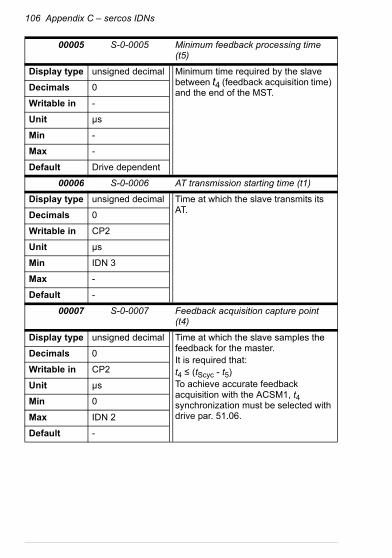
106 Appendix C – sercos IDNs
00005 S-0-0005 Minimum feedback processing time (t5)
Display type unsigned decimal Minimum time required by the slave between t4 (feedback acquisition time) and the end of the MST.
Decimals 0
Writable in -
Unit µs
Min -
Max -
Default Drive dependent
00006 S-0-0006 AT transmission starting time (t1)
Display type unsigned decimal Time at which the slave transmits its AT.
Decimals 0
Writable in CP2
Unit µs
Min IDN 3
Max -
Default -
00007 S-0-0007 Feedback acquisition capture point (t4)
Display type unsigned decimal Time at which the slave samples the feedback for the master.It is required that:t4 ≤ (tScyc - t5)To achieve accurate feedback acquisition with the ACSM1, t4 synchronization must be selected with drive par. 51.06.
Decimals 0
Writable in CP2
Unit µs
Min 0
Max IDN 2
Default -

Appendix C – sercos IDNs 107
00008 S-0-0008 Command value valid time (t3)
Display type unsigned decimal Time at which and after which the drive is allowed to access the command values received in the MDT.To achieve accurate command value latching with the ACSM1, t3 synchronization must be selected with drive par. 51.06.
Decimals 0
Writable in CP2
Unit µs
Min 0
Max IDN 2
Default -
00009 S-0-0009 Position of data record in MDT
Display type unsigned decimal Starting byte position of the data record for the slave within the MDT.
Decimals 0
Writable in CP2
Unit -
Min 1
Max -
Default -
00010 S-0-0010 Length of MDT
Display type unsigned decimal Length of the master data telegram (MDT) in bytes.
Decimals 0
Writable in CP2
Unit Byte
Min 4
Max 65534
Default -

108 Appendix C – sercos IDNs
00011 S-0-0011 Class 1 diagnostic
Display type binary Slave error information. Any class 1 error causes drive shutdown.For an explanation of the bits, see Class 1 diagnostic (IDN 00011).
Decimals 0
Writable in -
Unit -
Min -
Max -
Default 0
00012 S-0-0012 Class 2 diagnostic
Display type binary Drive warning information.For an explanation of the bits, see Manufacturer class 1 diagnostic (IDN 00129).
Decimals 0
Writable in -
Unit -
Min -
Max -
Default 0
00013 S-0-0013 Class 3 diagnostic
Display type binary Drive status information. When any bit in IDN 00013 is changed, the C3D change bit of the Status word is set. Effect of IDN 00013 changes to the C3D change bit can be masked by IDN 00098.For an explanation of the bits, see Class 3 diagnostic (IDN 00013).
Decimals 0
Writable in -
Unit -
Min -
Max -
Default 0
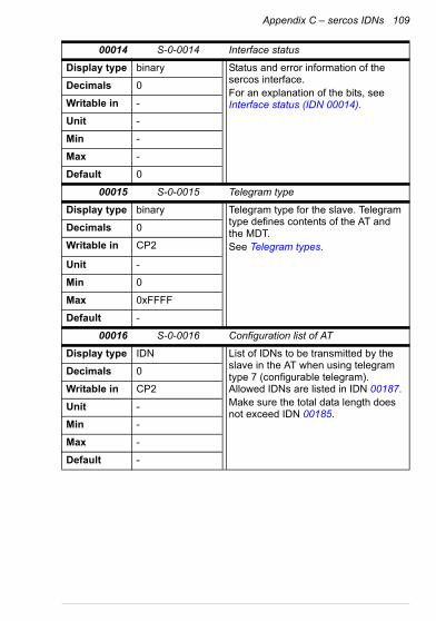
Appendix C – sercos IDNs 109
00014 S-0-0014 Interface status
Display type binary Status and error information of the sercos interface.For an explanation of the bits, see Interface status (IDN 00014).
Decimals 0
Writable in -
Unit -
Min -
Max -
Default 0
00015 S-0-0015 Telegram type
Display type binary Telegram type for the slave. Telegram type defines contents of the AT and the MDT.See Telegram types.
Decimals 0
Writable in CP2
Unit -
Min 0
Max 0xFFFF
Default -
00016 S-0-0016 Configuration list of AT
Display type IDN List of IDNs to be transmitted by the slave in the AT when using telegram type 7 (configurable telegram). Allowed IDNs are listed in IDN 00187.Make sure the total data length does not exceed IDN 00185.
Decimals 0
Writable in CP2
Unit -
Min -
Max -
Default -
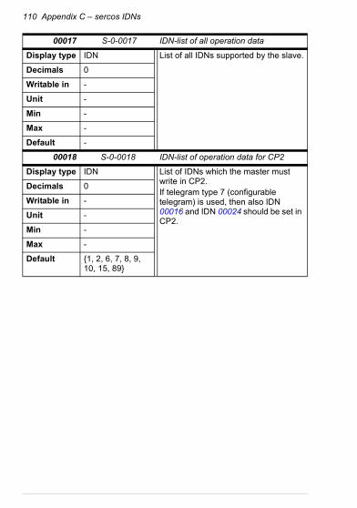
110 Appendix C – sercos IDNs
00017 S-0-0017 IDN-list of all operation data
Display type IDN List of all IDNs supported by the slave.
Decimals 0
Writable in -
Unit -
Min -
Max -
Default -
00018 S-0-0018 IDN-list of operation data for CP2
Display type IDN List of IDNs which the master must write in CP2.If telegram type 7 (configurable telegram) is used, then also IDN 00016 and IDN 00024 should be set in CP2.
Decimals 0
Writable in -
Unit -
Min -
Max -
Default {1, 2, 6, 7, 8, 9, 10, 15, 89}

Appendix C – sercos IDNs 111
00019 S-0-0019 IDN-list of operation data for CP3
Display type IDN List of IDNs which the master must write in CP3.No IDNs are absolutely required to be written in CP3 because all the IDNs, which the slave checks in the CP4 transition check, can be saved in the slave.
Decimals 0
Writable in -
Unit -
Min -
Max -
Default -
00021 S-0-0021 IDN-list of invalid operation data for CP2
Display type IDN If procedure command IDN 00127 (CP3 transition check) fails, then all IDNs which are considered invalid are placed in this list.
Decimals 0
Writable in -
Unit -
Min -
Max -
Default -
00022 S-0-0022 IDN-list of invalid operation data for CP3
Display type IDN If procedure command IDN 00128 (CP4 transition check) fails, then all IDNs which are considered invalid are placed in this list.
Decimals 0
Writable in -
Unit -
Min -
Max -
Default -

112 Appendix C – sercos IDNs
00024 S-0-0024 Configuration list of MDT
Display type IDN List of IDNs which will be transmitted by the master in the MDT when using telegram type 7 (configurable telegram). Allowed IDNs are listed in IDN 00188.Make sure the total data length does not exceed IDN 00186.
Decimals 0
Writable in CP2
Unit -
Min -
Max -
Default -
00025 S-0-0025 IDN-list of all procedure commands
Display type IDN List of all procedure command IDNs supported by the slave.
Decimals 0
Writable in -
Unit -
Min -
Max -
Default -
00028 S-0-0028 MST error counter
Display type unsigned decimal Count of invalid MSTs in CP3 and CP4. Counter is reset to 0 on the CP3 transition. Counter saturates to 65535.After two consecutive invalid MSTs, the slave switches back to CP0. Master can also reset the counter at will by writing any desired value.
Decimals 0
Writable in CP2, CP3, CP4
Unit -
Min 0
Max 65535
Default 0

Appendix C – sercos IDNs 113
00029 S-0-0029 MDT error counter
Display type unsigned decimal Counter of invalid MDTs in CP3 and CP4. Counter is reset to 0 on the CP3 transition. Counter saturates to 65535.Master can also reset the counter at will by writing any desired value.
Decimals 0
Writable in CP2, CP3, CP4
Unit -
Min 0
Max 65535
Default 0
00030 S-0-0030 Manufacturer version
Display type text Name and version of the fieldbus adapter firmware (eg, "OFCS0125").
Decimals 0
Writable in -
Unit -
Min -
Max -
Default OFCSnnnn
00032 S-0-0032 Primary operation mode
Display type binary See Supported modes of operation.
Decimals 0
Writable in CP2, CP3
Unit -
Min -
Max -
Default 0 Non-volatile

114 Appendix C – sercos IDNs
000330003400035
S-0-0033S-0-0034S-0-0035
Secondary operation mode 1Secondary operation mode 2Secondary operation mode 3
Display type binary See Supported modes of operation.
Decimals 0
Writable in CP2, CP3
Unit -
Min -
Max -
Default 0 Non-volatile
00036 S-0-0036 Velocity command value
Display type signed decimal Command value for the drive while in the velocity control operation mode.
Decimals 0
Writable in CP2, CP3, CP4
Unit vu
Min -231
Max 231 - 1
Default 0
00037 S-0-0037 Additive velocity command value
Display type signed decimal Added to the velocity command value IDN 00036. Result is the velocity command sent to the drive.
Decimals 0
Writable in CP2, CP3, CP4
Unit vu
Min -231
Max 231 - 1
Default 0

Appendix C – sercos IDNs 115
00040 S-0-0040 Velocity feedback value 1
Display type signed decimal Velocity feedback value from the drive.Operational only if actual velocity is available from the drive, see Required drive parameter configuration for ACSM1 drives.
Decimals 0
Writable in -
Unit vu
Min -
Max -
Default 0
00041 S-0-0041 Homing velocity
Display type signed decimal Velocity reference to be used by the drive during the drive-controlled homing procedure (see IDN 00148).Actual homing velocity may be limited to a smaller value by drive parameters.
Decimals 0
Writable in CP2, CP3
Unit vu
Min 0
Max 231 - 1
Default - Non-volatile
00042 S-0-0042 Homing acceleration
Display type signed decimal Maximum acceleration and deceleration during the drive-controlled homing procedure.Actual acceleration may be limited to a smaller value by IDN 00138 or drive parameters.
Decimals 0
Writable in CP2, CP3
Unit au
Min 0
Max 231 - 1
Default - Non-volatile

116 Appendix C – sercos IDNs
00043 S-0-0043 Velocity polarity parameter
Display type binary Polarity of the velocity input and output data can be reversed by this IDN.For an explanation of the bits, see Velocity control operation mode.
Decimals 0
Writable in CP2, CP3, CP4
Unit -
Min -
Max -
Default 0 Non-volatile
00044 S-0-0044 Velocity data scaling type
Display type binary See Velocity control operation mode.
Decimals 0
Writable in CP2, CP3
Unit -
Min 2
Max 0xA
Default 2 Non-volatile
00045 S-0-0045 Velocity data scaling factor
Display type unsigned decimal Scaling factor for velocity data when rotational scaling is selected. Value is fixed to 1.
Decimals 0
Writable in -
Unit -
Min -
Max -
Default 1

Appendix C – sercos IDNs 117
00046 S-0-0046 Velocity data scaling exponent
Display type signed decimal Scaling exponent for velocity data when rotational scaling is selected.See Velocity control operation mode.
Decimals 0
Writable in CP2, CP3
Unit -
Min -9
Max 0
Default -4 Non-volatile
00047 S-0-0047 Position command value
Display type signed decimal Command value for the drive while in the position control operation mode.
Decimals 0
Writable in CP2, CP3, CP4
Unit pu
Min -231
Max 231 - 1
Default 0
00049 S-0-0049 Positive position limit value
Display type signed decimal Maximum allowed distance in the positive direction.Position limits are used only when position data is being referred to the machine zero point (see IDN 00403), and position limits are enabled (see IDN 00055).
Decimals 0
Writable in CP2, CP3, CP4
Unit pu
Min -
Max -
Default 231 - 2 Non-volatile

118 Appendix C – sercos IDNs
00050 S-0-0050 Negative position limit value
Display type signed decimal Maximum allowed distance in the negative direction.Position limits are used only when position data is being referred to the machine zero point (see IDN 00403), and position limits are enabled (see IDN 00055).
Decimals 0
Writable in CP2, CP3, CP4
Unit pu
Min -231
Max 231 - 1
Default -231 Non-volatile
00051 S-0-0051 Position feedback value 1
Display type signed decimal Position feedback value from the drive.Operational only if actual position is available from the drive, see Required drive parameter configuration for ACSM1 drives.
Decimals 0
Writable in -
Unit pu
Min -
Max -
Default 0
00052 S-0-0052 Reference distance 1
Display type signed decimal Defines the distance between the machine zero point and the reference point. Master decides the position of the 'machine zero point' in relation to the 'reference point' with this IDN.
Decimals 0
Writable in CP2, CP3, CP4
Unit pu
Min -231
Max 231 - 1
Default 0 Non-volatile

Appendix C – sercos IDNs 119
00055 S-0-0055 Position polarity parameter
Display type binary Polarity of the position input and output data can be reversed by this IDN.For an explanation of the bits, see Position control operation mode.
Decimals 0
Writable in CP2, CP3, CP4
Unit -
Min -
Max -
Default 0 Non-volatile
00057 S-0-0057 Position window
Display type unsigned decimal When the difference between the position command value and the position feedback value is within the range of the position window, the drive sets the status "in position" (IDN 00336).
Decimals 0
Writable in CP2, CP3, CP4
Unit pu
Min 0
Max 231 - 1
Default 231 - 1 Non-volatile
00076 S-0-0076 Position data scaling type
Display type binary See Position control operation mode.Note: If option "Data reference at the motor shaft" is selected, the values of IDN 00121 and IDN 00122 (load gear ratio) are set to 1 automatically by the adapter module.
Decimals 0
Writable in CP2, CP3
Unit -
Min 0
Max 0xCA
Default - Non-volatile

120 Appendix C – sercos IDNs
00077 S-0-0077 Linear position data scaling factor
Display type signed decimal Although this IDN exists and is writable, it is not used in the scaling calculation. Linear position scaling is dictated only by the feed constant (IDN 00123).
Decimals 0
Writable in CP2, CP3, CP4
Unit -
Min 1
Max 1
Default 1
00078 S-0-0078 Linear position data scaling exponent
Display type signed decimal Although this IDN exists and is writable, it is not used in the scaling calculation. Linear position scaling is dictated only by the feed constant (IDN 00123).
Decimals 0
Writable in CP2, CP3, CP4
Unit -
Min -9
Max 0
Default -7 Non-volatile
00079 S-0-0079 Rotational position resolution
Display type unsigned decimal Resolution of position data (pu/rev) when rotational scaling is selected.See Position control operation mode.
Decimals 0
Writable in CP2, CP3, CP4
Unit pu/rev
Min 100
Max 100000000
Default - Non-volatile

Appendix C – sercos IDNs 121
00080 S-0-0080 Torque command value
Display type signed decimal Command value for the drive while in the torque control operation mode.
Decimals 0
Writable in CP2, CP3, CP4
Unit tu
Min -16000
Max 16000
Default 0
00081 S-0-0081 Additive torque command value
Display type signed decimal Added to the torque command value IDN 00080. Result is the torque command sent to the drive.
Decimals 0
Writable in CP2, CP3, CP4
Unit tu
Min -32768
Max 32767
Default 0
00084 S-0-0084 Torque feedback value
Display type signed decimal Torque feedback value from the drive.Operational only if actual torque is available from the drive, see Required drive parameter configuration for ACSM1 drives.
Decimals 0
Writable in -
Unit tu
Min -
Max -
Default 0

122 Appendix C – sercos IDNs
00085 S-0-0085 Torque polarity parameter
Display type binary Polarity of the torque input and output data can be reversed by this IDN.For an explanation of the bits, see Torque control operation mode.
Decimals 0
Writable in CP2, CP3, CP4
Unit -
Min -
Max -
Default 0 Non-volatile
00086 S-0-0086 Torque/force data scaling type
Display type binary See Torque control operation mode.
Decimals 0
Writable in CP2, CP3
Unit -
Min 0
Max 0xA
Default 0 Non-volatile
00087 S-0-0087 Transmit to transmit recovery time (tATAT)
Display type unsigned decimal Time required by the slave between multiple ATs sent by the same slave. Not significant when the slave has only one drive (such as the FSEA-21).
Decimals 0
Writable in -
Unit µs
Min -
Max -
Default 0

Appendix C – sercos IDNs 123
00088 S-0-0088 Receive to receive recovery time (tMTSY)
Display type unsigned decimal Minimum time required by the slave between the end of the MDT and the start of the MST.
Decimals 0
Writable in -
Unit µs
Min -
Max -
Default Drive dependent
00089 S-0-0089 MDT transmission starting time (t2)
Display type unsigned decimal Time at which the master will send the MDT during CP3 and CP4.
Decimals 0
Writable in CP2
Unit µs
Min 0
Max IDN 2
Default -
00090 S-0-0090 Command value proceeding time (tMTSG)
Display type unsigned decimal Minimum time required by the slave between the end of the MDT and t3 (command value valid time).
Decimals 0
Writable in -
Unit µs
Min -
Max -
Default Drive dependent
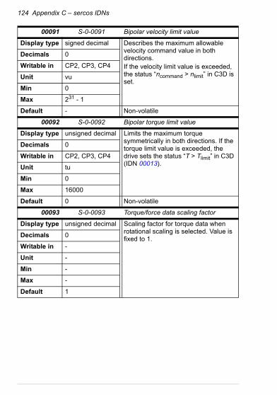
124 Appendix C – sercos IDNs
00091 S-0-0091 Bipolar velocity limit value
Display type signed decimal Describes the maximum allowable velocity command value in both directions.If the velocity limit value is exceeded, the status “ncommand > nlimit” in C3D is set.
Decimals 0
Writable in CP2, CP3, CP4
Unit vu
Min 0
Max 231 - 1
Default - Non-volatile
00092 S-0-0092 Bipolar torque limit value
Display type unsigned decimal Limits the maximum torque symmetrically in both directions. If the torque limit value is exceeded, the drive sets the status “T > Tlimit” in C3D (IDN 00013).
Decimals 0
Writable in CP2, CP3, CP4
Unit tu
Min 0
Max 16000
Default 0 Non-volatile
00093 S-0-0093 Torque/force data scaling factor
Display type unsigned decimal Scaling factor for torque data when rotational scaling is selected. Value is fixed to 1.
Decimals 0
Writable in -
Unit -
Min -
Max -
Default 1
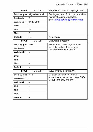
Appendix C – sercos IDNs 125
00094 S-0-0094 Torque/force data scaling exponent
Display type signed decimal Scaling exponent for torque data when rotational scaling is selected.See Torque control operation mode.
Decimals 0
Writable in CP2, CP3
Unit -
Min -4
Max 0
Default -2 Non-volatile
00095 S-0-0095 Diagnostic message
Display type text Status or error message from the slave. Describes, for example, procedure command results.
Decimals 0
Writable in -
Unit -
Min -
Max -
Default -
00096 S-0-0096 Slave arrangement (SLKN)
Display type hex Contains information on drive addresses of the slave's drives. FSEA-21 supports only one drive.
Decimals 0
Writable in -
Unit -
Min -
Max -
Default -

126 Appendix C – sercos IDNs
00097 S-0-0097 Mask class 2 diagnostic
Display type binary Effect of IDN 00012 bit changes to the C2D change bit of the Status word can be enabled or disabled one by one with this IDN.Bit value 1 = corresponding C2D bit is unmasked (enabled). If the C2D bit toggles, then Status word C2D change bit is set.
Decimals 0
Writable in CP2, CP3, CP4
Unit -
Min 0
Max 0xFFFF
Default 0xFFFF Non-volatile
00098 S-0-0098 Mask class 3 diagnostic
Display type binary Effect of IDN 00013 bit changes to the C3D change bit of the Status word can be enabled or disabled one by one with this IDN.Bit value 1 = corresponding C3D bit is unmasked (enabled). If the C3D bit toggles, then Status word C3D change bit is set.
Decimals 0
Writable in CP2, CP3, CP4
Unit -
Min 0
Max 0xFFFF
Default 0xFFFF Non-volatile
00099 S-0-0099 Reset class 1 diagnostic
Display type unsigned decimal Procedure command that attempts to reset:• Class 1 diagnostic (IDN 00011)• Errors in interface status (IDN
00014)• Manufacturer class 1 diagnostic
(IDN 00129)• Drive fault
Decimals 0
Writable in CP2, CP3, CP4
Unit -
Min -
Max -
Default -

Appendix C – sercos IDNs 127
00100 S-0-0100 Velocity loop proportional gain
Display type unsigned decimal Proportional gain (Kp) of the drive's speed controller. Scaling is drive specific.
Decimals 2
Writable in CP2, CP3
Unit -
Min 0
Max 20000
Default - Non-volatile
00101 S-0-0101 Velocity loop integral action time
Display type unsigned decimal Integration time of the drive's speed controller.Setting the maximum value 6553.5 ms causes the integrator to be switched off.
Decimals 1
Writable in CP2, CP3
Unit ms
Min 0
Max 65535
Default - Non-volatile
00103 S-0-0103 Modulo value
Display type signed decimal Active only if modulo format is selected (see IDN 00076). Value must be set according to IDN 00079 or IDN 00123, depending on whether rotational or linear position data scaling is selected. Limitation stems from the fact that it is not possible to arbitrarily select the modulo value in the drive.If the modulo value has not been set by the master, it will be set automatically according to the selected scaling mode.See Position control operation mode.
Decimals 0
Writable in CP2, CP3
Unit pu
Min 1
Max 231 - 1
Default 0 Non-volatile

128 Appendix C – sercos IDNs
00104 S-0-0104 Position loop KV-factor
Display type unsigned decimal Drive position control loop proportional gain.
Decimals 2
Writable in CP2, CP3
Unit (m/min)/mm
Min 0
Max 65535
Default - Non-volatile
00116 S-0-0116 Resolution of feedback 1
Display type unsigned decimal Drive pulse encoder resolution. Applicable only if a pulse encoder is used.Note: It is recommended to do encoder configuration at the drive - not via this IDN.
Decimals 0
Writable in CP2, CP3
Unit -
Min 0
Max 65535
Default - Non-volatile
00121 S-0-0121 Input revolutions of load gear
Display type signed decimal Drive gear ratio multiplier.Note: If option "Data reference at the motor shaft" is selected in IDN 00076, the adapter module sets the value to 1 automatically.
Decimals 0
Writable in CP2, CP3
Unit rev
Min 1
Max 231 - 1
Default 1 Non-volatile

Appendix C – sercos IDNs 129
00122 S-0-0122 Output revolutions of load gear
Display type signed decimal Drive gear ratio denominator.Note: If option "Data reference at the motor shaft" is selected in IDN 00076, the adapter module sets the value to 1 automatically.
Decimals 0
Writable in CP2, CP3
Unit rev
Min -231
Max 231 - 1
Default 1 Non-volatile
00123 S-0-0123 Feed constant
Display type unsigned decimal Resolution of position data (pu/rev) when linear scaling is selected.See Position control operation mode.
Decimals 0
Writable in CP2, CP3
Unit pu/rev
Min 1
Max 10000000
Default 100000 Non-volatile
00124 S-0-0124 Standstill window
Display type signed decimal When the velocity feedback value is less than or equal to the standstill window, the drive sets the status “nfeedback = 0” in C3D (see IDN 00331).
Decimals 0
Writable in CP2, CP3, CP4
Unit vu
Min 0
Max 231 - 1
Default 0 Non-volatile

130 Appendix C – sercos IDNs
00125 S-0-0125 Velocity threshold (nx)
Display type signed decimal If the velocity feedback value falls below the velocity threshold nx, the drive sets the status “nfeedback < nx” (IDN 00332) in C3D.
Decimals 0
Writable in CP2, CP3, CP4
Unit vu
Min 0
Max 231 - 1
Default 0 Non-volatile
00126 S-0-0126 Torque threshold
Display type signed decimal If the torque feedback value exceeds the torque threshold Tx, the drive sets the status “T > Tx” in C3D (IDN 00333).
Decimals 0
Writable in CP2, CP3, CP4
Unit tu
Min 0
Max 32767
Default 0 Non-volatile
00127 S-0-0127 CP3 transition check
Display type unsigned decimal Master uses this procedure command to instruct the slave to check that all necessary IDNs have been transferred before switching from CP2 to CP3. If the procedure command fails, IDN 00021 will contain a list of the invalid IDNs.
Decimals 0
Writable in CP2
Unit -
Min -
Max -
Default -

Appendix C – sercos IDNs 131
00128 S-0-0128 CP4 transition check
Display type unsigned decimal Master uses this procedure command to instruct the slave to check that all necessary IDNs have been transferred before switching from CP3 to CP4. If the procedure command fails, IDN 00022 will contain a list of the invalid IDNs.See also parameter CP4 TRANSITION MODE.
Decimals 0
Writable in CP3
Unit -
Min -
Max -
Default -
00129 S-0-0129 Manufacturer class 1 diagnostic
Display type binary Extension of IDN 00011 Class 1 diagnostic. Any class 1 error causes drive shutdown. For explanation of the bits, see Manufacturer class 1 diagnostic (IDN 00129).
Decimals 0
Writable in -
Unit -
Min -
Max -
Default 0
00134 S-0-0134 Master Control word
Display type binary Master can read the sercos Control word back via the service channel.
Decimals 0
Writable in -
Unit -
Min -
Max -
Default -

132 Appendix C – sercos IDNs
00135 S-0-0135 Drive Status word
Display type binary Master can read the sercos Status word via the service channel.
Decimals 0
Writable in -
Unit -
Min -
Max -
Default -
00138 S-0-0138 Bipolar acceleration limit value
Display type signed decimal Limits the maximum acceleration ability of the drive symmetrically in both directions. Does not affect the torque control or velocity control operation modes, only the position control operation mode or the homing procedure. Actual acceleration may be limited to a smaller value by other parameters.
Decimals 0
Writable in CP2, CP3
Unit au
Min 0
Max 231 - 1
Default - Non-volatile
00142 S-0-0142 Application type
Display type text Master may write and save an arbitrary text string into this IDN. If the master has not written this IDN, then the drive type is displayed.
Decimals 0
Writable in CP2, CP3, CP4
Unit -
Min -
Max -
Default - Non-volatile

Appendix C – sercos IDNs 133
00143 S-0-0143 SERCOS interface version
Display type text Version of the sercos interface.
Decimals 0
Writable in -
Unit -
Min -
Max -
Default V02.01
00147 S-0-0147 Homing parameter
Display type binary Configuration of the drive-controlled homing procedure.See Homing procedure.
Decimals 0
Writable in CP2, CP3
Unit -
Min -
Max -
Default - Non-volatile
00148 S-0-0148 Drive controlled homing procedure command
Display type unsigned decimal Procedure command to start the drive-controlled homing procedure.See Homing procedure.
Decimals 0
Writable in CP2, CP3, CP4
Unit -
Min -
Max -
Default -

134 Appendix C – sercos IDNs
00150 S-0-0150 Reference offset 1
Display type signed decimal Defines the distance between the reference marker pulse of position feedback 1 and the reference point. With absolute encoders this parameter is the distance between the real encoder zero point and the zero point of the position feedback value.
Decimals 0
Writable in CP2, CP3, CP4
Unit pu
Min -231
Max 231 - 1
Default - Non-volatile
00157 S-0-0157 Velocity window
Display type signed decimal If the difference between the total velocity command value and the velocity feedback is less than the velocity window, then the drive sets status “nfeedback = ncommand” in C3D (see IDN 00330).
Decimals 0
Writable in CP2, CP3, CP4
Unit vu
Min 0
Max 231 - 1
Default 0 Non-volatile
00159 S-0-0159 Monitoring window
Display type unsigned decimal Maximum allowable position deviation.If the position error exceeds this value, the drive sets an error "excessive position deviation" in C1D (see IDN 00011).
Decimals 0
Writable in CP2, CP3, CP4
Unit pu
Min 0
Max 231 - 1
Default 536 870 911 Non-volatile

Appendix C – sercos IDNs 135
00160 S-0-0160 Acceleration data scaling type
Display type binary See Acceleration data scaling.
Decimals 0
Writable in CP2, CP3
Unit -
Min 0
Max 0xA
Default 0x2 Non-volatile
00161 S-0-0161 Acceleration data scaling factor
Display type unsigned decimal Scaling factor for acceleration data when rotational scaling is selected. Value is fixed to 1.
Decimals 0
Writable in -
Unit -
Min -
Max -
Default 1
00162 S-0-0162 Acceleration data scaling exponent
Display type signed decimal Scaling exponent for acceleration data when rotational scaling is selected.See Acceleration data scaling.
Decimals 0
Writable in CP2, CP3
Unit -
Min -6
Max 0
Default -3 Non-volatile

136 Appendix C – sercos IDNs
00181 S-0-0181 Manufacturer class 2 diagnostic
Display type binary Fixed value is 0; manufacturer class 2 diagnostic is not used by the adapter module.
Decimals 0
Writable in -
Unit -
Min -
Max -
Default 0
00185 S-0-0185 Length of the configurable data record in the AT
Display type unsigned decimal Maximum AT data length, in bytes, which is supported by the slave when using telegram type 7 (configurable telegram).
Decimals 0
Writable in -
Unit Byte
Min -
Max -
Default 40
00186 S-0-0186 Length of the configurable data record in the MDT
Display type unsigned decimal Maximum MDT data record length for the slave, in bytes, which is supported by the slave when using telegram type 7 (configurable telegram).
Decimals 0
Writable in -
Unit Byte
Min -
Max -
Default 40

Appendix C – sercos IDNs 137
00187 S-0-0187 I IDN-list of configurable data in the AT
Display type IDN List of IDNs which can be configured in the AT when using telegram type 7 (configurable telegram).
Decimals 0
Writable in -
Unit -
Min -
Max -
Default {41, 51, 84, 189, 32872, 32873, 32874}
00188 S-0-0188 IDN-list of configurable data in the MDT
Display type IDN List of IDNs which can be configured in the MDT for the slave when using telegram type 7 (configurable telegram).
Decimals 0
Writable in -
Unit -
Min -
Max -
Default {36, 37, 47, 80, 81, 32869, 32870, 32871}
00189 S-0-0189 Following distance
Display type signed decimal Indicates the current position error.Following distance = position command value - position feedback value.
Decimals 0
Writable in -
Unit pu
Min -
Max -
Default 0

138 Appendix C – sercos IDNs
00191 S-0-0191 Cancel reference point procedure command
Display type unsigned decimal Resets the position feedback value status (see IDN 00403). If executed during the homing procedure, it is also aborted.
Decimals 0
Writable in CP2, CP3, CP4
Unit -
Min -
Max -
Default -
00192 S-0-0192 IDN-list of backup operation data
Display type IDN List of IDNs which determine the configuration of the slave.
Decimals 0
Writable in -
Unit -
Min -
Max -
Default {32, 33, 34, 35, 41, 42, 43, 44, 46, 49, 50, 52, 55, 57, 76, 77, 78, 79, 85, 86, 91, 92, 94, 97, 98, 100, 101, 103, 104, 116, 121, 122, 123, 124, 125, 126, 138, 142, 147, 150, 157, 159, 160, 162, 206, 207, 296, 301, 303, 305, 307, 413, 414, 415, 416, 32773, 32774, 32775, 32776, 32788, 32789, 32790}
00206 S-0-0206 Drive on delay time
Display type unsigned decimal Adjustable delay between drive on command from the master and release of the drive reference.Drive starts to modulate when the master sets Control word bit 15 "drive on", but the drive follows command values after this delay. Note: With the ACSM1 the granularity of this delay is 500 µs.
Decimals 1
Writable in CP2, CP3
Unit ms
Min 0
Max 65535
Default 0

Appendix C – sercos IDNs 139
00207 S-0-0207 Drive off delay time
Display type unsigned decimal Adjustable delay between stopping of the drive and disabling of the power stage.After the master resets Control word bit 15 "drive off command" and the motor actual speed falls below an internal limit, the drive off delay time starts. During this delay the inverter is kept live and the motor magnetized for quick restart.Note: With the ACSM1 the granularity of this delay is 1 ms.
Decimals 1
Writable in CP2, CP3
Unit ms
Min 0
Max 65535
Default - Non-volatile
00264 S-0-0264 Backup working memory procedure command
Display type unsigned decimal Saves all storable IDNs into the fieldbus adapter and the drive.Check IDN 00095 afterwards to verify that all IDNs were successfully saved.
Decimals 0
Writable in CP2, CP3
Unit -
Min -
Max -
Default -
00292 S-0-0292 List of supported operation modes
Display type unsigned decimal List of operation modes supported by the drive.
Decimals 0
Writable in -
Unit -
Min -
Max -
Default -

140 Appendix C – sercos IDNs
00296 S-0-0296 Velocity feed forward gain
Display type unsigned decimal Drive speed feed forward gain.Note: Velocity feed forward gain is effective also in mode “position control, with following error” since the corresponding drive parameter is effective regardless of the operation mode.
Decimals 2
Writable in CP2, CP3
Unit -
Min 0
Max 1000
Default - Non-volatile
00300 S-0-0300 Real-time control bit 1
Display type unsigned decimal State of the real-time control bit 1 is also visible via the service channel.See Real time bits.
Decimals 0
Writable in -
Unit -
Min -
Max -
Default 0
00301 S-0-0301 Allocation of real-time control bit 1
Display type IDN Selects the destination IDN of the Control word real-time control bit 1.See Real time bits.
Decimals 0
Writable in CP2, CP3, CP4
Unit -
Min -
Max -
Default 0 Non-volatile

Appendix C – sercos IDNs 141
00302 S-0-0302 Real-time control bit 2
Display type unsigned decimal State of the real-time control bit 2 is also visible via the service channel.See Real time bits.
Decimals 0
Writable in -
Unit -
Min -
Max -
Default 0
00303 S-0-0303 Allocation of real-time control bit 2
Display type IDN Selects the destination IDN of the Control word real-time control bit 2.See Real time bits.
Decimals 0
Writable in CP2, CP3, CP4
Unit -
Min -
Max -
Default 0 Non-volatile
00304 S-0-0304 Real-time status bit 1
Display type unsigned decimal State of the real-time status bit 1 is also visible via the service channel.See Real time bits.
Decimals 0
Writable in -
Unit -
Min -
Max -
Default 0

142 Appendix C – sercos IDNs
00305 S-0-0305 Allocation of real-time status bit 1
Display type IDN Selects the source IDN for the Status word real-time status bit 1.See Real time bits.
Decimals 0
Writable in CP2, CP3, CP4
Unit -
Min -
Max -
Default 0 Non-volatile
00306 S-0-0306 Real-time status bit 2
Display type unsigned decimal State of the real-time status bit 2 is also visible via the service channel.See Real time bits.
Decimals 0
Writable in -
Unit -
Min -
Max -
Default 0
00307 S-0-0307 Allocation of real-time status bit 2
Display type IDN Selects the source IDN for the Status word real-time status bit 2.See Real time bits.
Decimals 0
Writable in CP2, CP3, CP4
Unit -
Min -
Max -
Default 0 Non-volatile

Appendix C – sercos IDNs 143
00330 S-0-0330 Status “nfeedback = ncommand”
Display type unsigned decimal |velocity command - velocity feedback| ≤ velocity window.Effective in the velocity control operation mode and if actual velocity is available from the drive. See IDN 00157.
Decimals 0
Writable in -
Unit -
Min -
Max -
Default 0
00331 S-0-0331 Status "nfeedback = 0"
Display type unsigned decimal |velocity feedback| ≤ standstill window.Effective if actual velocity is available from the drive. See IDN 00124.
Decimals 0
Writable in -
Unit -
Min -
Max -
Default 0
00332 S-0-0332 Status "nfeedback < nx"
Display type unsigned decimal |velocity feedback| ≤ velocity threshold.Effective if actual velocity is available from the drive.See IDN 00125.
Decimals 0
Writable in -
Unit -
Min -
Max -
Default 0
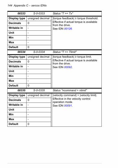
144 Appendix C – sercos IDNs
00333 S-0-0333 Status "T >= Tx"
Display type unsigned decimal |torque feedback| ≥ torque threshold.Effective if actual torque is available from the drive.See IDN 00126.
Decimals 0
Writable in -
Unit -
Min -
Max -
Default 0
00334 S-0-0334 Status "T >= Tlimit"
Display type unsigned decimal |torque feedback| ≥ torque limit.Effective if actual torque is available from the drive.See IDN 00092.
Decimals 0
Writable in -
Unit -
Min -
Max -
Default 0
00335 S-0-0335 Status "ncommand > nlimit"
Display type unsigned decimal |velocity command| > |velocity limit|.Effective in the velocity control operation mode.See IDN 00091.
Decimals 0
Writable in -
Unit -
Min -
Max -
Default 0

Appendix C – sercos IDNs 145
00336 S-0-0336 Status "In position"
Display type unsigned decimal |position error| ≤ position window.Effective in the position control operation mode.See IDN 00057.
Decimals 0
Writable in -
Unit -
Min -
Max -
Default 0
00390 S-0-0390 Diagnostic number
Display type unsigned decimal Provides the same information as the MODULE LED when it is blinking red. Indicates the number of blinks of the red LED.See LEDs for the meaning of the error codes.
Decimals 0
Writable in -
Unit -
Min -
Max -
Default 0
00400 S-0-0400 Home switch
Display type unsigned decimal Value for this IDN is taken from DCU Status word bit 31. Works only if the home switch digital input value is routed to DCU SW bit 31 at the drive. If any other data is routed to DCU SW bit 31, then this IDN is inoperative.For example, in the ACSM1 set par. 50.11 FBA SW B15 SRC = P.6.11 POS CORR STATUS.10.
Decimals 0
Writable in -
Unit -
Min -
Max -
Default 0

146 Appendix C – sercos IDNs
00403 S-0-0403 Position feedback value status
Display type unsigned decimal Bit 0 of this IDN is '1' when the zero point of the position feedback value is the machine zero point, in other words, after a successful homing procedure. Bit 0 is '0' when procedure command IDN 00148 or 00191 is started or the drive has lost its reference to the machine zero point somehow.
Decimals 0
Writable in -
Unit -
Min -
Max -
Default 0
00413 S-0-0413 Bit number allocation of real-time control bit 1
Display type unsigned decimal Selects the destination bit position for the Control word real-time control bit 1.See Real time bits.
Decimals 0
Writable in CP2, CP3, CP4
Unit -
Min 0
Max 31
Default 0 Non-volatile
00414 S-0-0414 Bit number allocation of real-time control bit 2
Display type unsigned decimal Selects the destination bit position for the Control word real-time control bit 2.See Real time bits.
Decimals 0
Writable in CP2, CP3, CP4
Unit -
Min 0
Max 31
Default 0 Non-volatile

Appendix C – sercos IDNs 147
00415 S-0-0415 Bit number allocation of real-time status bit 1
Display type unsigned decimal Selects the source bit position for the Status word real-time status bit 1.See Real time bits.
Decimals 0
Writable in CP2, CP3, CP4
Unit -
Min 0
Max 31
Default 0 Non-volatile
00416 S-0-0416 Bit number allocation of real-time status bit 2
Display type unsigned decimal Selects the source bit position for the Status word real-time status bit 2.See Real time bits.
Decimals 0
Writable in CP2, CP3, CP4
Unit -
Min 0
Max 31
Default 0 Non-volatile
32770 P-0-0002 SERCOS drive address
Display type unsigned decimal Configuration parameter group parameter 02. See the description of the drive parameter in Drive configuration.
Decimals 0
Writable in CP2, CP3, CP4
Unit -
Min 0
Max 254
Default - Non-volatile

148 Appendix C – sercos IDNs
32771 P-0-0003 SERCOS bitrate
Display type unsigned decimal Configuration parameter group parameter 03. See the description of the drive parameter in Drive configuration.
Decimals 0
Writable in CP2, CP3, CP4
Unit -
Min 2
Max 16
Default - Non-volatile
32772 P-0-0004 SERCOS TX power
Display type unsigned decimal Configuration parameter group parameter 04. See the description of the drive parameter in Drive configuration.
Decimals 0
Writable in CP2, CP3, CP4
Unit -
Min 1
Max 4
Default - Non-volatile
32773 P-0-0005 Profile
Display type unsigned decimal Configuration parameter group parameter 05. See the description of the drive parameter in Drive configuration.
Decimals 0
Writable in CP2, CP3, CP4
Unit -
Min 0
Max 1
Default - Non-volatile

Appendix C – sercos IDNs 149
32774 P-0-0006 Drive SW sync position
Display type unsigned decimal Configuration parameter group parameter 06.See the description of the drive parameter in Drive configuration.
Decimals 0
Writable in CP2, CP3, CP4
Unit -
Min 0
Max 4
Default - Non-volatile
32775 P-0-0007 Cyclic high TX position
Display type unsigned decimal Configuration parameter group parameter 07. See the description of the drive parameter in Drive configuration.
Decimals 0
Writable in CP2, CP3, CP4
Unit 0/1
Min 0
Max 1
Default - Non-volatile
32776 P-0-0008 CP4 transition mode
Display type unsigned decimal Configuration parameter group parameter 08. See the description of the drive parameter in Drive configuration.
Decimals 0
Writable in CP2, CP3, CP4
Unit 0/1
Min 0
Max 1
Default - Non-volatile

150 Appendix C – sercos IDNs
32788 P-0-0020 ACT position time displacement
Display type signed decimal Apparent time offset for position feedback values. Usable in certain conditions only, see Appendix B – Time offset adjustment.
Decimals 0
Writable in CP2, CP3, CP4
Unit µs
Min -2000
Max 32767
Default 0 Non-volatile
32789 P-0-0021 REF position time displacement
Display type signed decimal Apparent time offset for position command values. Usable in certain conditions only, see Appendix B – Time offset adjustment.
Decimals 0
Writable in CP2, CP3, CP4
Unit µs
Min -2000
Max IDN 2
Default 0 Non-volatile
32790 P-0-0022 Drive position control mode
Display type unsigned decimal Configuration parameter group parameter 22.See the description of the drive parameter in Drive configuration.
Decimals 0
Writable in CP2, CP3
Unit -
Min 0
Max 1
Default - Non-volatile

Appendix C – sercos IDNs 151
32798 P-0-0030 Parameter number
Display type unsigned decimal Drive parameter number for reading or writing drive parameters. Format: decimal xxyy = P.xx.yy.For example, value 5101 means drive par. 51.01.See IDN 32801 and IDN 32802.
Decimals 2
Writable in CP2, CP3, CP4
Unit -
Min 101
Max 9999
Default 0
32799 P-0-0031 Drive parameter value
Display type unsigned decimal Data value which was read from the drive or value to be written to the drive.See IDN 32801 and IDN 32802.
Decimals 0
Writable in CP2, CP3, CP4
Unit -
Min -
Max -
Default 0
32800 P-0-0032 Drive parameter data type
Display type unsigned decimal Data type code of the last drive parameter read or written by procedure command IDN 32801 or IDN 32802.
Decimals 0
Writable in -
Unit -
Min -
Max -
Default 0

152 Appendix C – sercos IDNs
32801 P-0-0033 Read drive parameter
Display type unsigned decimal Procedure command for reading drive parameters. Parameter to be read is specified by IDN 32798. After reading, the parameter value is placed into IDN 32799 and its data type code is placed into IDN 32800.
Decimals 0
Writable in CP2, CP3, CP4
Unit -
Min -
Max -
Default -
32802 P-0-0034 Write drive parameter
Display type unsigned decimal Procedure command for writing drive parameters. Parameter to be written is specified by IDN 32798 and data is taken from IDN 32799. After writing, the data type code of the parameter is placed into IDN 32800.
Decimals 0
Writable in CP2, CP3, CP4
Unit -
Min -
Max -
Default -
32868 P-0-0100 Last drive fault code
Display type hex Last fault code read from the drive. See the drive manual for explanation of the fault codes.
Decimals 0
Writable in -
Unit -
Min -
Max -
Default 0

Appendix C – sercos IDNs 153
32869 P-0-0101 DCU CW
Display type hex Drive native Control word. Do not write this IDN unless the transparent profile is selected.
Decimals 0
Writable in CP2, CP3, CP4
Unit -
Min -
Max -
Default 0
32870 P-0-0102 DCU REF1
Display type hex Drive native reference value 1. Do not write this IDN unless the transparent profile is selected.
Decimals 0
Writable in CP2, CP3, CP4
Unit -
Min -
Max -
Default 0
32871 P-0-0103 DCU REF2
Display type hex Drive native reference value 2. Do not write this IDN unless the transparent profile is selected.
Decimals 0
Writable in CP2, CP3, CP4
Unit -
Min -
Max -
Default 0

154 Appendix C – sercos IDNs
32872 P-0-0104 DCU SW
Display type hex Drive native Status word.
Decimals 0
Writable in -
Unit -
Min -
Max -
Default 0
32873 P-0-0105 DCU ACT1
Display type hex Drive native actual value 1.
Decimals 0
Writable in -
Unit -
Min -
Max -
Default 0
32874 P-0-0106 DCU ACT2
Display type hex Drive native actual value 2.
Decimals 0
Writable in -
Unit -
Min -
Max -
Default 0

Appendix C – sercos IDNs 155
IDN value storage
The IDNs marked as non-volatile can be saved into the non-volatile memory of the adapter module, or alternatively, some IDNs' values can be kept in the drive parameters. The procedure command IDN 00264 Backup working memory procedure command saves all the non-volatile IDNs. Note that the drive may save its parameters automatically, independently of the adapter module, and thus the IDNs whose values are kept in the drive parameters may be saved even if IDN 00264 has not been invoked. IDNs saved in the adapter module can be removed by parameter 09 ERASE FBA CONFIG but this does not affect the IDNs which are kept in the drive parameters.
32868 P-0-0200 Nominal torque
Display type unsigned decimal Drive nominal torque value that corresponds to 100% torque.Scale is 10-3 Nm, eg, value 1300 = 1.3 Nm.
Decimals 3
Writable in -
Unit Nm
Min -
Max -
Default -

156 Appendix C – sercos IDNs
IDNs saved in the flash memory
The IDNs whose values are saved into the flash memory of the adapter module are listed in the table below.
IDN Name
S-0-0033 Secondary operation mode 1
S-0-0034 Secondary operation mode 2
S-0-0035 Secondary operation mode 3
S-0-0043 Velocity polarity parameter
S-0-0044 Velocity data scaling type
S-0-0046 Velocity data scaling exponent
S-0-0049 Positive position limit value
S-0-0050 Negative position limit value
S-0-0052 Reference distance 1
S-0-0055 Position polarity parameter
S-0-0057 Position window
S-0-0078 Linear position data scaling exponent
S-0-0085 Torque polarity parameter
S-0-0086 Torque/force data scaling type
S-0-0094 Torque/force data scaling exponent
S-0-0097 Mask class 2 diagnostic
S-0-0098 Mask class 3 diagnostic
S-0-0103 Modulo value
S-0-0123 Feed constant
S-0-0124 Standstill window
S-0-0125 Velocity threshold (nx)
S-0-0126 Torque threshold (Tx)
S-0-0142 Application type
S-0-0157 Velocity window
S-0-0159 Monitoring window
S-0-0160 Acceleration data scaling type

Appendix C – sercos IDNs 157
S-0-0162 Acceleration data scaling exponent
S-0-0206 Drive on delay time
S-0-0301 Allocation of real-time control bit 1
S-0-0303 Allocation of real-time control bit 2
S-0-0305 Allocation of real-time status bit 1
S-0-0307 Allocation of real-time status bit 2
S-0-0413 Bit number allocation of real-time control bit 1
S-0-0414 Bit number allocation of real-time control bit 2
S-0-0415 Bit number allocation of real-time status bit 1
S-0-0416 Bit number allocation of real-time status bit 2
IDN Name

158 Appendix C – sercos IDNs
IDNs that affect ACSM1 parameters
The IDNs that affect ACSM1 drive parameters and vice versa are listed in the table below. The table does not include ACSM1 group 51 parameters, see section FSEA-21 configuration parameters – group A (group 1) for these parameters.
Warning! Do not change any of the drive parameters which affect IDN values via a PC tool, a panel or byIDN P-0-0034 (32802) when the sercos ring is in CP4.
After you have changed drive parameters, use parameter 51.27 FBA PAR REFRESH to read the new settings into the adapter module. Failure to comply may cause incorrect operation, such as an improper control response.
IDN Name ACSM1 parameter
S-0-0041 Homing velocity 62.07 HOMING SPEEDREF
S-0-0042 Homing acceleration (ACSM1 fw. versions < UMFI151x)65.06 PROF ACC 165.07 PROF DEC 1
(ACSM1 fw. versions > UMFI151x)62.27 HOMING ACC62.28 HOMING DEC
S-0-0076 Position data scaling type 60.02 POS AXIS MODE
S-0-0091 Bipolar velocity limit value 20.01 MAXIMUM SPEED20.02 MINIMUM SPEED
S-0-0092 Bipolar torque limit value 20.06 MAXIMUM TORQUE20.07 MINIMUM TORQUE
S-0-0100 Velocity loop proportional gain 28.02 PROPORT GAIN
S-0-0101 Velocity loop integral action time
28.03 INTEGRATION TIME

Appendix C – sercos IDNs 159
S-0-0104 Position loop KV-factor 71.03 POS CTRL GAIN
S-0-0116 Resolution of feedback 1 93.01 TTL1 PULSE NR
S-0-0121 Input revolutions of load gear 71.07 GEAR RATIO MUL
S-0-0122 Output revolutions of load gear 71.08 GEAR RATIO DIV
S-0-0138 Bipolar acceleration limit value 70.05 POS ACCEL LIM70.06 POS DECEL LIM
S-0-0147 Homing parameter 62.01 HOMING METHOD
S-0-0207 Drive off delay time 22.06 ZERO SPEED DELAY
S-0-0296 Velocity feed forward gain 71.04 P CTRL FEED GAIN
P-0-0200 Nominal torque 98.01 TORQ NOM SCALE
IDN Name ACSM1 parameter

160 Appendix C – sercos IDNs

Further information
Product and service inquiriesAddress any inquiries about the product to your local ABB representative, quoting the type designation and serial number of the unit in question. A listing of ABB sales, support and service contacts can be found by navigating to www.abb.com/searchchannels.
Product trainingFor information on ABB product training, navigate to www.abb.com/drives and select Training courses.
Providing feedback on ABB Drives manualsYour comments on our manuals are welcome. Go to www.abb.com/drives and select Document Library – Manuals feedback form (LV AC drives).
Document library on the InternetYou can find manuals and other product documents in PDF format on the Internet. Go to www.abb.com/drives and select Document Library. You can browse the library or enter selection criteria, for example a document code, in the search field.

Contact us
www.abb.com/driveswww.abb.com/solarwww.abb.com/windpowerwww.abb.com/drivespartners
3AUA0000068941 Rev B (EN) 2013-11-19