Embed Size (px)
Citation preview
SPECIFICATIONSPowerVoltage . . . . . . . . . . . . . . . . . . . . . . . . . . . . . . . . . . . . . . .24VDCPower Supply . . . . . . . . . . . .Watt Stopper FS-PP Power PackCurrent Consumption . . . . . . . . . . . . . . . . . . . . . . . . . . . .43mATime Delay Adjustment . . . . . . . . . . . . 5, 10, 15 or 30 minutes
Test Mode . . . . . . . . . . .5 second time delay for 5 minutesFS-505 coverage@ 8’ height at 20° angle from vertical . . . . . .
. . . . . . . .24’ min. linear, 6’ min. at 90° on each sideFS-505C coverage@ 10’ height parallel to floor . . . . . . . . . . . .
. . . . . . . . . . . . . . . . . . . . .12’ min. radius from centerOperating Temperature . . . . . . . . . . .32° to 131°F (0° to 55°C)Dimensions (see template)Body . . . 5.2” x 1.25” x 0.62” (132.4mm x 32.2mm x 15.7mm)Mounting base . . . . . . . . .6.125” x 1.25” (155.2mm x 32.2mm)Mounting hole centers . . . .5.75” x 0.8” (145.2mm x 20.0mm)
FS-505C a n d FS - 5 0 540kHz Ultrasonic Occupancy Sensor
L ow Vo l tage • Ceiling/Wall Fixture Mount
US Patents: 4,787,7225,189,393
DESCRIPTION AND OPERATIONThe FS-505 and FS-505C occupancy sensors turn lighting on and off based onoccupancy. The sensors use ultrasonic sensing technology. Once the space isvacant and the time delay elapses (adjustable from 5 to 30 minutes), lightswill turn off.
The FS-505 and FS-505C operate at 24VDC. They are designed for insta l l a t i o nin a light fixture within 2 feet of an ass o c i a ted power supply. The power supply fo rthe sensors is a FS-PP power pack mounted inside a light fixture. Each WattStopper FS-PP power pack can supply power for one FS-505 or FS-505C.
The sensors are equipped with a 2’ long cable fitted with a shielded maleRJ45 plug. The FS-PP has a corresponding female RJ45 receptacle. Thiscable carries power to the sensor and the 24VDC maintained output to thepower pack to signal that lights should be on. Optional cables and connectorsare available for alternate configurations.
Important, there is an initial warm-up period: It may take up to a minute before the lights turn on due to a sensor warm-upperiod required during initial power-up. This occurs during installation orafter a lengthy power failure only.
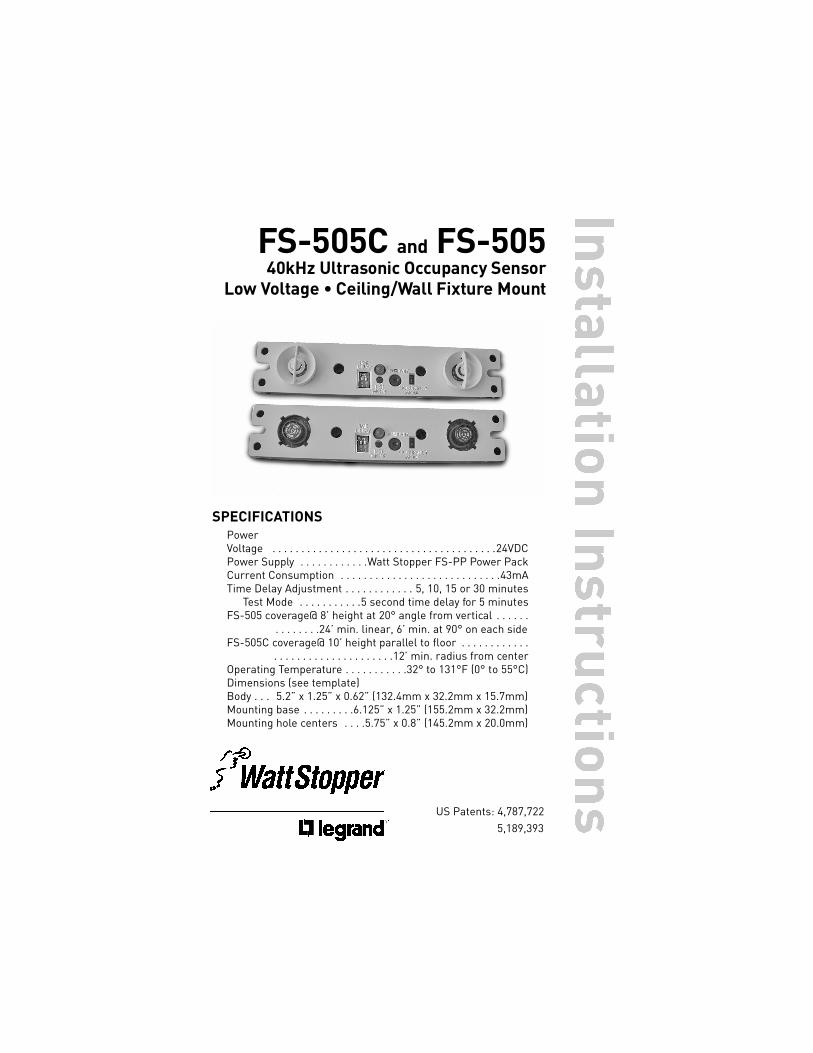
Fig 1a: FS-505C Mounted p a ra llel to floor in ceiling fixture
Call 800.879.8585 or 972.578.1699 for Technical Support
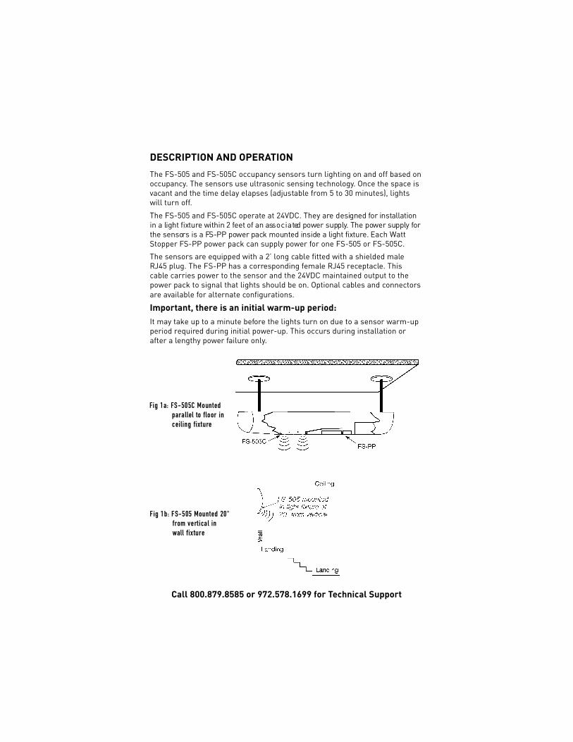
Fig 1b: FS-505 Mounted 20° f rom vert ical in wall fix ture
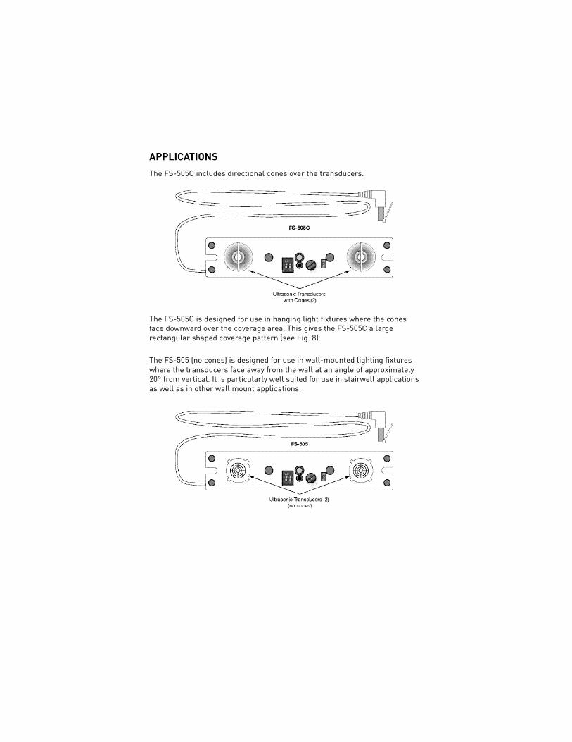
APPLICATIONSThe FS-505C includes directional cones over the transducers.
The FS-505C is designed for use in hanging light fixtures where the conesface downward over the coverage area. This gives the FS-505C a largerectangular shaped coverage pattern (see Fig. 8).
The FS-505 (no cones) is designed for use in wall-mounted lighting fixtureswhere the transducers face away from the wall at an angle of approximately20° from vertical. It is particularly well suited for use in stairwell applicationsas well as in other wall mount applications.
1. Install the FS-PP as directed in the installation instructions provided withthe power pack. Review Figures 2, 3, and 11 to determine appropriate loadwiring to the FS-PP and Occupancy Mode Switch setting for the FS-505.
2. Determine an appropriate mounting location inside the light fixture.
3. See template for dimensions to determine cut-out and mounting holelocations in the fixture.
4. Install the sensor to the inside of the fixture using screws.
5. Plug the FS-505 into the FS-PP.
6. Restore power from the circuit breaker.
INSTALLATION
Visit our website for FAQs: www.wattstopper.com
CAUTIONTURN THE POWER OFF AT THE CIRCUIT BREAKER
BEFORE INSTALLING THE SENSOR.
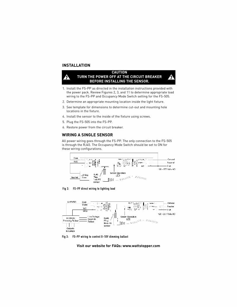
WIRING A SINGLE SENSORAll power wiring goes through the FS-PP. The only connection to the FS-505is through the RJ45. The Occupancy Mode Switch should be set to ON forthese wiring configurations.
Fig 2: FS-PP di rect wi ring to light ing load
Fig 3: FS-PP wiring to control 0-10V dimming ballast
Call 800.879.8585 or 972.578.1699 for Technical Support
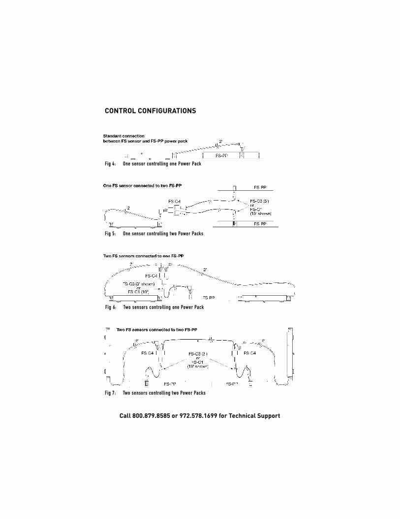
Fig 5: One sensor controlling two Power Pa ck s
CONTROL CONFIGURATIONS
Fig 6: Two sensors controlling one Power Pa ck
Fig 7: Two sensors controlling two Power Pa ck s
Fig 4: One sensor controlling one Power Pa ck
Visit our website for FAQs: www.wattstopper.com
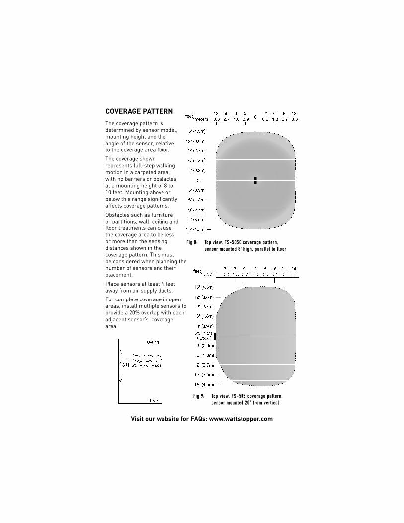
COVERAGE PATTERNThe coverage pattern isdetermined by sensor model,mounting height and theangle of the sensor, relativeto the coverage area floor.
The coverage shownrepresents full-step walkingmotion in a carpeted area,with no barriers or obstaclesat a mounting height of 8 to10 feet. Mounting above orbelow this range significantlyaffects coverage patterns.
Obstacles such as furnitureor partitions, wall, ceiling andfloor treatments can causethe coverage area to be lessor more than the sensingdistances shown in thecoverage pattern. This mustbe considered when planning thenumber of sensors and theirplacement.
Place sensors at least 4 feetaway from air supply ducts.
For complete coverage in openareas, install multiple sensors toprovide a 20% overlap with eachadjacent sensor’s coveragearea.
Fig 9: Top view, FS-505 cove rage pattern,sensor mounted 20° from ve r t i c a l
Fig 8: Top view, FS-505C cove rage pattern, sensor mounted 8’ high, parallel to floor
Before making adjustments, install furniture, turn lighting circuits on, and setHVAC systems to the overridden/on position. VAV systems should be set totheir highest airflow. Set the Time Delay to the desired settings. See “TimeDelay Switches” on the next page.
To Test Occupancy Sensors1. Set the Sensitivity adjustment to about mid-range.2. Activate the Test Mode using the test mode button.3. Move out of the controlled area – the lights will turn off in about 5 seconds
from the last flash of the LED.* If the LED continues to flash, the sensor isdetecting some kind of movement. Change the sensitivity adjustment to alower setting (a few degrees counterclockwise) and repeat this step untilthe LED does not flash and the lights turn off.
* If Reverse-Occupancy is enabled (the lighting load is wired to a normallyclosed contact and the sensor’s Occupancy Mode Switch is ON), operationof the load is also reversed during Test mode. For example, at this stage oftesting, the lights will turn ON in about 5 seconds from the last flash of theLED. See Occupancy Mode Switch for more information.
4. Walk into the controlled area. If the lights don’t turn on, increase thesensitivity (a few degrees clockwise) and try again. Repeat this procedureuntil the LED does not flash and the lights turn off. If the lights turn offwhile the room is occupied, it may be necessary to increase the sensitivity.
5. Allow the test period to expire or push the test button again. The sensorwill now be in its operating mode.
SENSOR ADJUSTMENT
WARNING
DO NOT OVERTURN TRIMPOT WHEN ADJUSTING THE SENSOR.
Visit our website for FAQs: www.wattstopper.com
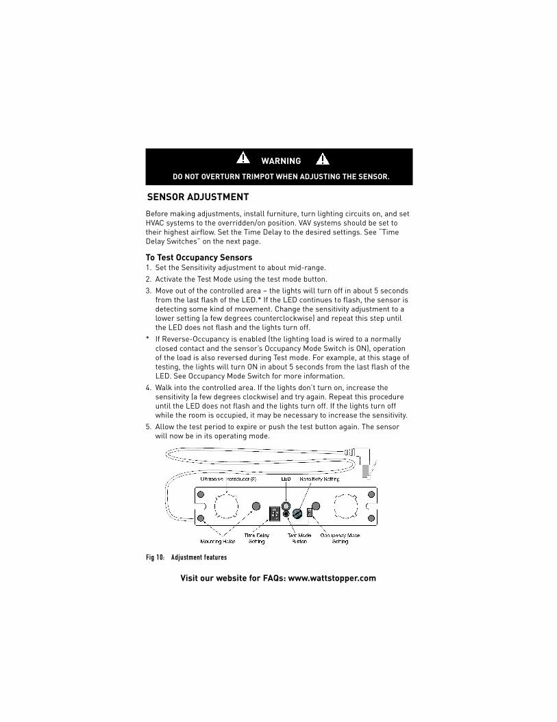
Fig 10: Adjustment features
LEDThe LED flashes every time the sensor detects motion. The LED is also usedto indicate other sensor status such as test mode, lamp burn-in, andoverride. When the LED flashes at a constant rate of one second on then onesecond off, the sensor is in the burn-in mode. When the sensor is in testmode the LED flashes to indicate occupancy detections. When the sensor isin override mode the LED glows steady.
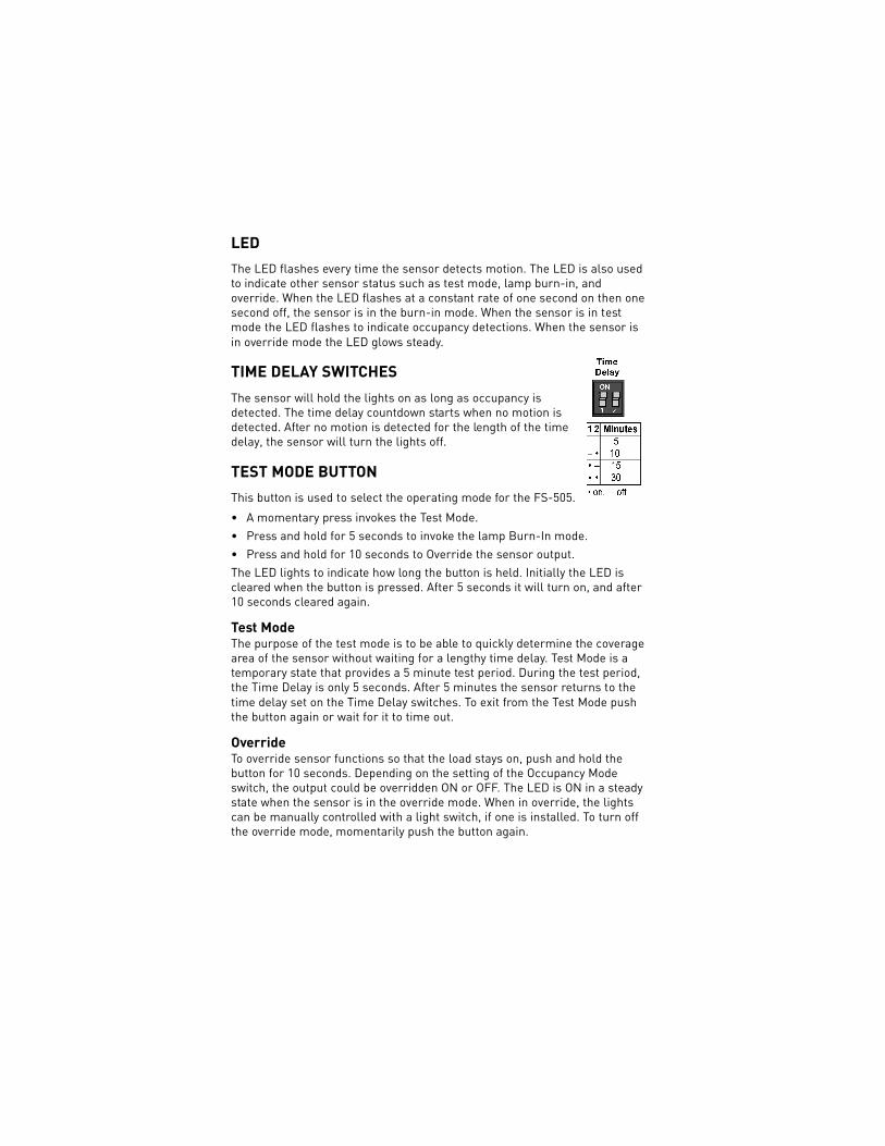
TIME DELAY SWITCHESThe sensor will hold the lights on as long as occupancy isdetected. The time delay countdown starts when no motion isdetected. After no motion is detected for the length of the timedelay, the sensor will turn the lights off.
TEST MODE BUTTONThis button is used to select the operating mode for the FS-505.
• A momentary press invokes the Test Mode.• Press and hold for 5 seconds to invoke the lamp Burn-In mode.• Press and hold for 10 seconds to Override the sensor output.The LED lights to indicate how long the button is held. Initially the LED iscleared when the button is pressed. After 5 seconds it will turn on, and after10 seconds cleared again.
Test Mode The purpose of the test mode is to be able to quickly determine the coveragearea of the sensor without waiting for a lengthy time delay. Test Mode is atemporary state that provides a 5 minute test period. During the test period,the Time Delay is only 5 seconds. After 5 minutes the sensor returns to thetime delay set on the Time Delay switches. To exit from the Test Mode pushthe button again or wait for it to time out.
OverrideTo override sensor functions so that the load stays on, push and hold thebutton for 10 seconds. Depending on the setting of the Occupancy Modeswitch, the output could be overridden ON or OFF. The LED is ON in a steadystate when the sensor is in the override mode. When in override, the lightscan be manually controlled with a light switch, if one is installed. To turn offthe override mode, momentarily push the button again.
Call 800.879.8585 or 972.578.1699 for Technical Support
Burn-In Some lamp and ballast manufacturers recommend running lamps at fulloutput for their first 72 hours of operation. The burn-in function initiates a 72-hour burn-in period. To start the burn-in process, push and hold the buttonfor 5 seconds. The lamps will stay on for 72 hours continuously regardless ofoccupancy status. After 72 hours, the sensor returns to normal function. Toindicate the sensor is in burn-in mode, the LED flashes rapidly andcontinuously for the full 72 hours. To turn off the burn-in mode, momentarilypush the button again.
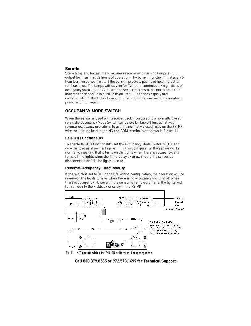
OCCUPANCY MODE SWITCHWhen the sensor is used with a power pack incorporating a normally closedrelay, the Occupancy Mode Switch can be set for fail-ON functionality, orreverse-occupancy operation. To use the normally closed relay on the FS-PP,wire the lighting load to the NC and COM terminals as shown in Figure 11.
Fail-ON FunctionalityTo enable fail-ON functionality, set the Occupancy Mode Switch to OFF andwire the load as shown in Figure 11. In this configuration the sensor worksnormally, meaning that it turns on the lights when there is occupancy, andturns off the lights when the Time Delay expires. Should the sensor bedisconnected or fail, the lights turn on.
Reverse-Occupancy FunctionalityIf the swtich is set to ON in the N/C wiring configuration, the operation will bereversed. The lights turn on when there is no occupancy and turn off whenthere is occupancy. However, if the sensor is removed or fails, the lights willturn on due to the kickback circuitry in the FS-PP.
Fig 11: N/C contact wiring for Fail-ON or Reve r s e - O c c u p a n cy mode.
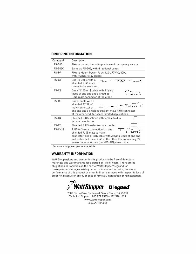
Catalog # DescriptionFS-505 Fixture mount, low voltage ultrasonic occupancy sensorFS-505C Same as FS-505, with directional conesFS-PP Fixture Mount Power Pack: 120-277VAC, 60Hz
with NO/NC Relay outputFS-C1 One 10’ cable with a
shielded RJ45 maleconnector at each end.
FS-C2 One 6” (152mm) cable with 3 flying leads at one end and a shielded RJ45 male connector at the other.
FS-C3 One 3’ cable with ashielded 90° RJ45male connector atone end and a shielded straight male RJ45 connectorat the other end, for space-limited applications.
FS-C4 Shielded RJ45 splitter with female to dualfemale receptacles.
FS-C5 Shielded RJ45 male-to-male coupler.FS-CK-2 RJ45 to 3-wire connection kit: one
shielded RJ45 male to maleconnector, one 6-inch cable with 3 flying leads at one endand a shielded male RJ45 at the other. For connecting FSsensor to an alternate (non-FS-PP) power pack.
ORDERING INFORMATION
Sensors and power packs are White.
WARRANTY INFORMATIONWatt Stopper/Legrand warranties its products to be free of defects inmaterials and workmanship for a period of five (5) years. There are noobligations or liabilities on the part of Watt Stopper/Legrand forconsequential damages arising out of, or in connection with, the use orperformance of this product or other indirect damages with respect to loss ofproperty, revenue or profit, or cost of removal, installation or reinstallation.
2800 De La Cruz Boulevard, Santa Clara, CA 95050Technical Support: 800.879.8585 • 972.578.1699
www.wattstopper.com06074r3 10/2006