Embed Size (px)
Citation preview
1 / 8
FrostGuard 120 V120 V PREASSEMBLED ELECTRIC HEATING CABLES FOR PIPE FREEZE PROTECTION AND ROOF & GUTTER DE-ICING INSTALLATION INSTRUCTIONS
THERMAL BUILDING SOLUTIONS EN-RaychemFrostGuard120V-IM-H59486 05/16
Pipe Freeze Protection
Roof and gutter de-icing: standard roof
Roof and gutter de-icing: standing seam metal roof
DESCRIPTIONFrostGuard 120 V preassembled self-regulating heating cables are designed for residential and light commercial metal and plastic pipe freeze protection and roof & gutter de-icing applications. FrostGuard 120 V heating cables are available in 6, 12, 18, 24, 36, 50, 75 and 100 foot lengths, and each comes assembled with a 6-ft power cord and lighted plug.
KIT CONTENTS1 FrostGuard preassembled electric heating cable
2 Roof and gutter labels
2 Pipe labels
ADDITIONAL ITEMS REQUIRED BUT NOT SUPPLIED FOR PIPE APPLICATIONS• Ground-fault protected outlet (GFCI)• Waterproof thermal insulation (e.g. preformed foam)• Raychem H903 Application Tape and Electric Traced Labels
ADDITIONAL ITEMS REQUIRED BUT NOT SUPPLIED FOR ROOF & GUTTER APPLICATIONS• Raychem H913/H914 Roof Clips (10 clips for each 7 linear feet of
roof edge)• Raychem H915 Hanger Bracket (1 for each downspout, 2 if looping)• UV Resistant cable ties• Ground-fault protected outlet (GFCI)
APPROVALS
-WS
FIRE AND SHOCK HAZARD. This product is an electrical device that must be installed correctly to ensure proper operation and to prevent shock or fire. Read these important warnings and carefully follow all the installation instructions.
• To minimize the danger of fire from sustained electrical arcing if the heating cable is damaged or improperly installed, and to comply with the requirements of Pentair Thermal Building Solutions agency certifications, and national electrical codes,
ground-fault equipment protection must be used on each heating cable branch circuit. Arcing may not be stopped by conventional circuit protection.
• For pipe freeze protection applications, use only fire-resistant insulation materials such as preformed foam or fiberglass.
• Do not damage the heating cable and power cord or plug. Remove any damaged cables from service immediately.
• Do not use any wire or metal clamps to attach the cable to the pipe. Use tape (1/2 inch wide to 1 inch wide) or plastic cable ties.
• Do not install the heating cable underneath any roof covering for roof and gutter de-icing.
• Leave these installation instructions with the user for future reference.
WARNING:

THERMAL BUILDING SOLUTIONS EN-RaychemFrostGuard120V-IM-H59486 05/16 2 / 8
General requirements for pipe freeze protection:
• FrostGuard heating cables may be used on metal and plastic water pipes but not on flexible vinyl tubing (such as garden hoses).
• FrostGuard heating cables are not intended for use inside any pipes, for freeze protection of liquids other than water, or for use in classified hazardous locations.
• Install with a minimum of 1/2” fire-resistant, waterproof thermal insulation.
• Never use on any pipes that may exceed 150°F (65°C).• Do not use an extension cord.
General instructions:
• Install only in accessible locations; do not install behind walls or where the cable would be hidden.
• Do not run the heating cable through walls, ceilings, or floors.• Connect only to ground-fault protected outlets that have been
installed in accordance with all prevailing national and local codes and standards and are protected from rain and other water.
Electrical codes
Articles 422 and 427 of the National Electrical Code (NEC), and Part 1, Section 62 of the Canadian Electrical Code (CEC), govern the installation of FrostGuard heating cable for pipe freeze protec-tion and must be followed.Important: For the Pentair Thermal Building Solutions warranty to be valid, you must comply with all the requirements outlined in these guidelines.
All thermal and design information provided here is based upon a “standard” installation with heating cable fastened to an insulated pipe. For any other application or method of installation, consult Pentair Thermal Building Solutions at (800) 545-6258
FrostGuard 120 V (FG1) heating cable selection for pipe freeze protection:
Use the tables to below to select the correct heating cable. Add 1 foot to your pipe length for each valve or spigot on your pipe system.The charts assume the lowest outside temperature is 0°F (–18°C), with a minimum of 1/2” thick waterproof, fire-resistant thermal insulation (preformed foam). For protection to –20°F (–29°C), use 1” thick insulation.
Important: All thermal and design information provided here is based upon a “standard installation”: heating cable fastened to a pipe and thermally insulated. For any other method of installation or application, consult Pentair Thermal Building Solutions at (800) 545-6258.
Table 1 Metal Pipes Table 2 Plastic Pipes
Table 1 Metal Pipes
Table 2 Plastic Pipes
Add 1 foot to your pipe length for each valve or spigot on your pipe system. If cable selected is longer than the pipe, spiral it evenly along the entire pipe.
Add 1 foot to your pipe length for each valve or spigot on your pipe system. If cable selected is longer than the pipe, spiral it evenly along the entire pipe.
Pipe length (ft)
Pipe
dia
met
er (i
n)
Pipe length (ft)
Pipe
dia
met
er (i
n)
2 1/221 1/211/2
2 1/221 1/211/2
FG2-6L
FG2-12L
FG2-18L
FG2-24L
Pipe
dia
met
er (i
n) 2 1/221 1/211/2
Pipe
dia
met
er (i
n) 2 1/221 1/211/2 FG1-6P FG1-12P FG1-18P FG1-24P FG1-36P FG1-50P FG1-75P FG1-100P
FG1-6P FG1-12P FG1-18P FG1-24P FG1-36P FG1-50P FG1-75P FG1-100P
Pipe length (ft)
Pipe length (ft)
10 20 30 40 50 60 70 80 90 1000
10 20 30 40 50 60 70 80 90 1000
10 20010 200
FG2-6L
FG2-12L
FG2-18L
FG2-24L
Pipe Freeze Protection

3 / 8THERMAL BUILDING SOLUTIONS EN-RaychemFrostGuard120V-IM-H59486 05/16
Tape orcable ties
FG heatingcable
12 inches
Waterproof covering
Pipe label
End view
1/2 in insulation
Figure 1. Straight-traced installation
Tape orcable ties
FG heatingcable
12 inches
10 feetGlass tape(typical)
Heatingcable
Tape after spiralingheating cable on pipe
Wrap loops in opposite directionPull heating cable
loop length
Apply glass tape beforespiraling heating cable on pipe
Waterproof covering1/2 in insulation
Pipe label
Figure 2. Spiral-traced installation
Heating cable installation
1. Prepare for installation.• Store the heating cable in a clean, dry place.• Complete piping pressure test.• Prior to installing the cable, remove any sharp surfaces on
the pipe that might damage the heating cable.• Review the FrostGuard heating cable design and compare
to materials received to verify that you have the proper FrostGuard heating cable.
• Walk the system and plan the routing of the FrostGuard heating cable on the pipe.
2. Position and attach heating cable to pipe.• Be sure all piping to be traced is dry.• Install heating cable, using straight tracing Figure 1, or spiral-
ing Figure 2.• For straight tracing, install the heating cable on a lower half
of the pipe; for example, in the 4 o’clock or 8 o’clock position.• Be sure to install the additional heating cable required for
valves, flanges, etc. as shown in Figures 1 and 2.
• When the design calls for spiraling, begin by suspending a loop every 10 feet as shown in Figure 2. To determine the loop length, divide the FrostGuard length by your pipe length and multiply by 10. For example, if you are using a 50 ft Frost-Guard on a 40 foot pipe, leave a 12-foot loop of heating cable at every 10-foot section of pipe. Grasp the loop in its center and wrap it around the pipe. Even out the distance between spirals by sliding the wraps along the pipe. Use glass tape to secure the center of the loop to the pipe.
• Fasten FrostGuard heating cable to the pipe at 1-foot intervals using H903 fiberglass application tape or nylon cable ties. Do not use vinyl electrical tape, duct tape, metal bands, or wire.
• If excess cable remains at the end of the pipe, double it back along the pipe.
3. Check the installation.• Prior to installing thermal insulation, make sure the heating
cable is free of mechanical damage (from cuts, clamps, etc.) and thermal damage (from solder, overheating, etc.).

THERMAL BUILDING SOLUTIONS EN-RaychemFrostGuard120V-IM-H59486 05/16 4 / 8
Figure 3. Insulation
Cord label
Pipe label
Strain relief
Figure 4. Strain relief Note: Pipes must be fully insulated.
4. Install thermal insulation.• A reliable FrostGuard system depends on properly installed
and dry, weatherproofed thermal insulation.• Ensure that at least 1/2” of preformed foam or equivalent
thermal insulation is used and that all piping, including valves, joints, and wall penetrations, has been fully insulated as shown in Figure 3.
• For protection to -20°F (-29°C), use 1” thick insulation.• Install the insulation on the piping as soon as possible to mini-
mize the potential for mechanical damage after installation.• Be sure the FrostGuard 120 V label is visible on the outside of
the thermal insulation.
5. Finishing the installation.• To prevent damage to the heating cable or cord, secure the
power cord (cold lead) with a plastic cable tie, glass cloth tape, or duct tape as shown in Figure 4.
• Two labels indicating the presence of electric pipe heat-ing cable are included with the heating cable. Attach the two “Electric Traced” labels on the outer surface of the pipe insulation at suitable intervals to indicate the presence of FrostGuard electric heating cable.
6. Starting the system.• Pentair Thermal Building Solutions recommends that the sys-
tem be tested per the “Cable testing and maintenance” section below.
• Plug the heating cable into a 120-V ground-fault protected outlet.
• Check the circuit breaker to verify power to the cable.• Standing water in the pipe should feel warm within an hour.
Cable testing and maintenance
Using a 2500-Vdc megohmmeter, check the insulation resistance between both of the rectangular (power) prongs on the plug and the round (ground) prong after installing the heating cable. Mini-mum reading should be 1000 megohms.
Record the original values for each circuit, and compare subse-quent readings taken during regular maintenance schedules to the original values.
If the readings fall below 1000 megohms, replace the FrostGuard cable with a new unit. Do not attempt to repair the unit.
WARNING: Fire and Shock Hazard. Damaged heating cable can cause electrical shock, arcing, and
fire. Do not attempt to repair or energize damaged heating cable. Remove it at once and replace with a new length.
5 / 8THERMAL BUILDING SOLUTIONS EN-RaychemFrostGuard120V-IM-H59486 05/16
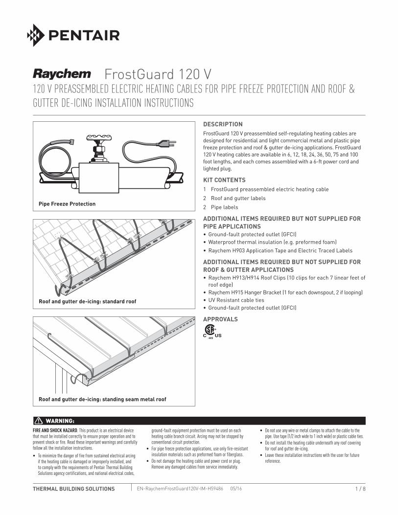
General requirements for roof & gutter de-icing:
• FrostGuard is designed to remove melt water, not accumulated snow.
• FrostGuard heating cable will not keep snow or ice from falling off the roof. Snow fences or snow guards should be used to eliminate snow movement. For the names of manufacturers of snow guards or snow fences, contact Pentair Thermal Building Solutions at (800) 545-6258.
• FrostGuard heating cables may be used on:- Roofs made from all types of standard roofing materials,
including shake, shingle, rubber, tar, wood, metal, and plastic.- Gutters made from standard materials, including metal and
plastic.- Downspouts made from standard materials, including metal
and plastic.
• Do not use an extension cord.• Do not install the heating cable underneath any roof covering for
roof and gutter de-icing.• Install only in accessible locations; do not install behind walls or
where the cable would be hidden.• Do not run the heating cable through walls, ceilings, or floors.• Connect only to ground-fault protected outlets that have been
installed in accordance with all prevailing national and local codes and standards and are protected from rain and other water.
Electrical codes
Article 426 of the National Electrical Code (NEC), and Part 1, Sec-tion 62 of the Canadian Electrical Code (CEC), govern the installa-tion of FrostGuard heating cables for roof and gutter de-icing and must be followed.Important: For the Pentair Thermal Building Solutions warranty to be valid, you must comply with all the requirements outlined in these guidelines.
All design information provided here is based on a “standard” shake or shingle roof application. For any other application or method of installation, consult Pentair Thermal Building Solutions at (800) 545-6258.
Roof & Gutter De-icing
Note: Route and secure the heating cable to avoid possible mechanical damage, such as from ladders, etc.
THERMAL BUILDING SOLUTIONS EN-RaychemFrostGuard120V-IM-H59486 05/16 6 / 8
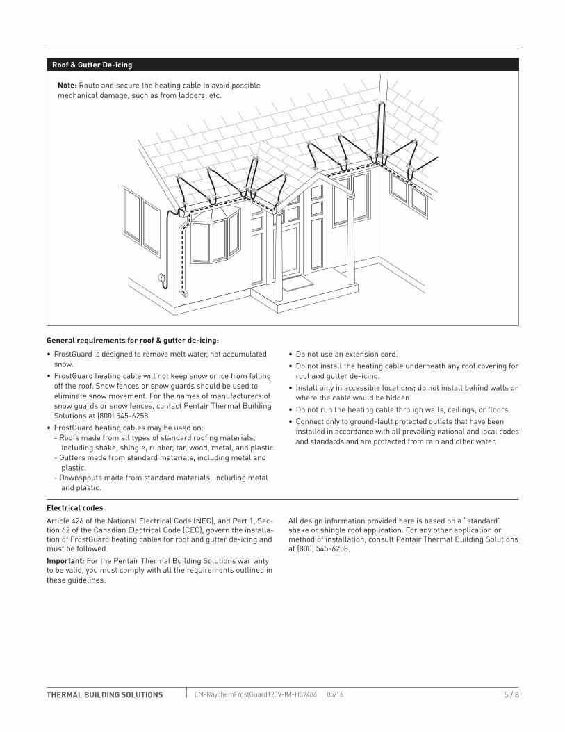
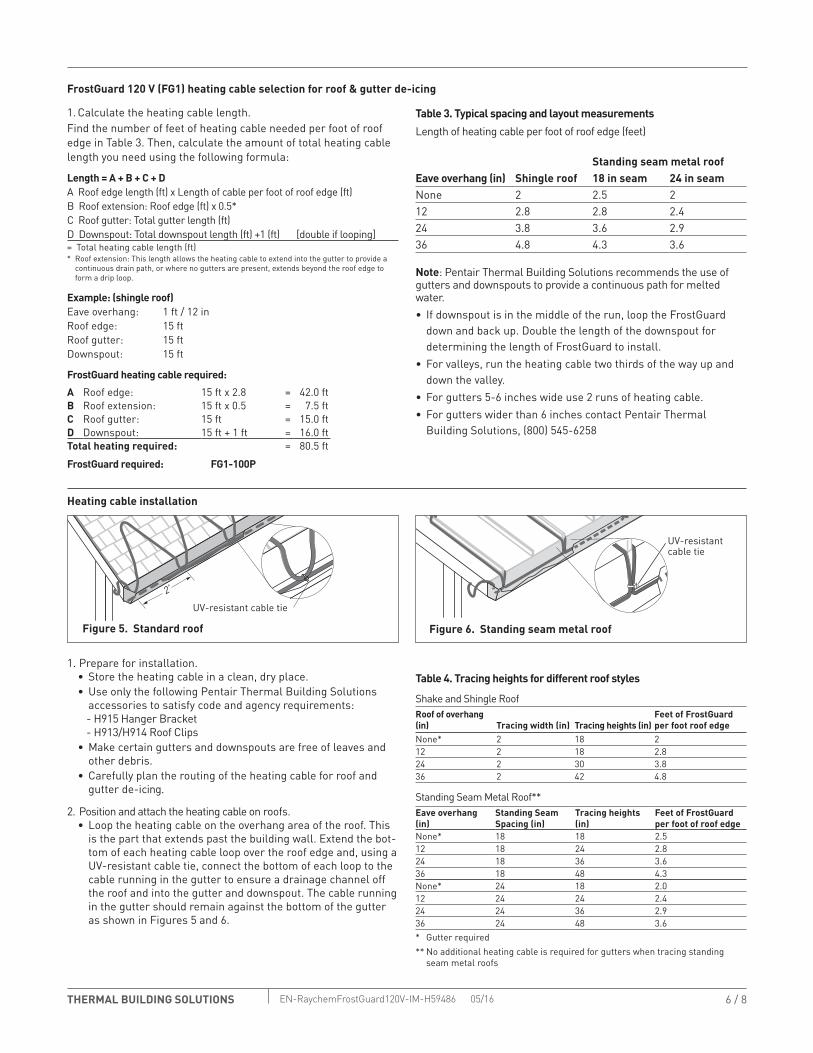
FrostGuard 120 V (FG1) heating cable selection for roof & gutter de-icing
1. Calculate the heating cable length.Find the number of feet of heating cable needed per foot of roof edge in Table 3. Then, calculate the amount of total heating cable length you need using the following formula:
Length = A + B + C + DA Roof edge length (ft) x Length of cable per foot of roof edge (ft)B Roof extension: Roof edge (ft) x 0.5*C Roof gutter: Total gutter length (ft)D Downspout: Total downspout length (ft) +1 (ft) [double if looping]= Total heating cable length (ft)* Roof extension: This length allows the heating cable to extend into the gutter to provide a
continuous drain path, or where no gutters are present, extends beyond the roof edge to form a drip loop.
Example: (shingle roof)Eave overhang: 1 ft / 12 inRoof edge: 15 ftRoof gutter: 15 ftDownspout: 15 ft
FrostGuard heating cable required:
A Roof edge: 15 ft x 2.8 = 42.0 ftB Roof extension: 15 ft x 0.5 = 7.5 ftC Roof gutter: 15 ft = 15.0 ftD Downspout: 15 ft + 1 ft = 16.0 ftTotal heating required: = 80.5 ft
FrostGuard required: FG1-100P
Table 3. Typical spacing and layout measurementsLength of heating cable per foot of roof edge (feet)
Standing seam metal roofEave overhang (in) Shingle roof 18 in seam 24 in seamNone 2 2.5 212 2.8 2.8 2.424 3.8 3.6 2.936 4.8 4.3 3.6
Note: Pentair Thermal Building Solutions recommends the use of gutters and downspouts to provide a continuous path for melted water.• If downspout is in the middle of the run, loop the FrostGuard
down and back up. Double the length of the downspout for determining the length of FrostGuard to install.
• For valleys, run the heating cable two thirds of the way up and down the valley.
• For gutters 5-6 inches wide use 2 runs of heating cable.• For gutters wider than 6 inches contact Pentair Thermal
Building Solutions, (800) 545-6258
Heating cable installation
1. Prepare for installation.• Store the heating cable in a clean, dry place.• Use only the following Pentair Thermal Building Solutions
accessories to satisfy code and agency requirements:- H915 Hanger Bracket- H913/H914 Roof Clips
• Make certain gutters and downspouts are free of leaves and other debris.
• Carefully plan the routing of the heating cable for roof and gutter de-icing.
2. Position and attach the heating cable on roofs.• Loop the heating cable on the overhang area of the roof. This
is the part that extends past the building wall. Extend the bot-tom of each heating cable loop over the roof edge and, using a UV-resistant cable tie, connect the bottom of each loop to the cable running in the gutter to ensure a drainage channel off the roof and into the gutter and downspout. The cable running in the gutter should remain against the bottom of the gutter as shown in Figures 5 and 6.
Table 4. Tracing heights for different roof styles
Shake and Shingle RoofRoof of overhang (in) Tracing width (in) Tracing heights (in)
Feet of FrostGuard per foot roof edge
None* 2 18 212 2 18 2.824 2 30 3.836 2 42 4.8
Standing Seam Metal Roof**Eave overhang (in)
Standing Seam Spacing (in)
Tracing heights (in)
Feet of FrostGuard per foot of roof edge
None* 18 18 2.512 18 24 2.824 18 36 3.636 18 48 4.3None* 24 18 2.012 24 24 2.424 24 36 2.936 24 48 3.6* Gutter required** No additional heating cable is required for gutters when tracing standing
seam metal roofs
2'
UV-resistant cable tie
Figure 5. Standard roof
UV-resistantcable tie
Figure 6. Standing seam metal roof
7 / 8THERMAL BUILDING SOLUTIONS EN-RaychemFrostGuard120V-IM-H59486 05/16
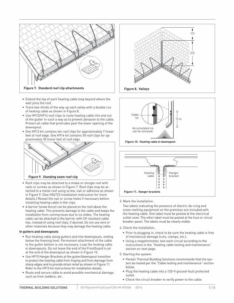
Figure 7. Standard roof clip attachments
2/3
1/3
Figure 8. Valleys
• Extend the top of each heating cable loop beyond where the wall joins the roof.
• Trace two-thirds of the way up each valley with a double run of heating cable as shown in Figure 8.
• Use H913/H914 roof clips to route heating cable into and out of the gutter in such a way as to prevent abrasion to the cable. Protect all cable that protrudes past the lower opening of the downspout.
• One H913 kit contains ten roof clips for approximately 7 linear feet of roof edge. One H914 kit contains 50 roof clips for ap-proximately 35 linear feet of roof edge.
• Roof clips may be attached to a shake or shingle roof with nails or screws as shown in Figure 7. Roof clips may be at-tached to a metal roof using screw, nail or adhesive as shown in Figure 9. (See H56723 installation instruction for more details.) Reseal the nail or screw holes if necessary before installing heating cable in the clips.
• A barrier (snow fence) can be placed on the roof above the heating cable. This prevents damage to the cable and keeps the installation from coming loose due to ice slides. The heating cable can be attached to the barrier with UV-resistant cable ties, instead of using roof clips, if desired. Do not use wire or other materials because they may damage the heating cable.
In gutters and downspouts• Run heating cable along gutters and into downspouts, ending
below the freezing level. Permanent attachment of the cable to the gutter bottom is not necessary. Loop the heating cable in downspouts. Do not leave the end of the FrostGuard in air at the end of the downspout as shown in Figure 10.
• Use H915 Hanger Brackets at the gutter/downspout transition to protect the heating cable from fraying and from damage from sharp edges and to provide strain relief as shown in Figure 11. Refer to the H915 kit instructions for installation details.
• Route and secure cable to avoid possible mechanical damage, such as from ladders, etc.
3. Mark the installation.Two labels indicating the presence of electric de-icing and snow-melting equipment on the premises are included with the heating cable. One label must be posted at the electrical outlet cover. The other label must be posted at the fuse or circuit breaker panel. The labels must be clearly visible.
4. Check the installation.• Prior to plugging in, check to be sure the heating cable is free
of mechanical damage (cuts, clamps, etc.).• Using a megohmmeter, test each circuit according to the
instructions in the “Heating cable testing and maintenance” section on next page.
5. Starting the system.• Pentair Thermal Building Solutions recommends that the sys-
tem be tested per the “Cable testing and maintenance” section below.
• Plug the heating cable into a 120-V ground-fault protected outlet.
• Check the circuit breaker to verify power to the cable.
Figure 9. Standing seam roof clip
Accumulated icecan be removed.
12 in
Figure 10. Heating cable in downspout
Cabletie
Heatingcable
Hangerbracket
Figure 11. Hanger brackets

8 / 8THERMAL BUILDING SOLUTIONS EN-RaychemFrostGuard120V-IM-H59486 05/16 PN P000002072
WWW.PENTAIRTHERMAL.COM
© 2016 Pentair.
NORTH AMERICATel: +1.800.545.6258Fax: +1.800.527.5703Tel: +1.650.216.1526Fax: [email protected]
Pentair and FrostGuard are owned by Pentair or its global affiliates. All other trademarks are the property of their respective owners. Pentair reserves the right to change specifications without prior notice.
Heating cable testing and maintenance
Make sure that gutter and downspouts are free of leaves and other debris prior to the winter season.Using a 2500-Vdc megohmmeter (2500 Vdc minimum), unplug the FrostGuard and test the unit by checking the insulation resistance between the flat blade and the ground pin in the plug. Minimum reading should be 1000 megohms regardless of FrostGuard length.Record the original values for each circuit. Take additional read-ings during regularly scheduled maintenance and compare to the original value. If the readings fall below 1000 megohms, inspect heating cables and insulation for signs of damage.
Product specifications
FG1-6P FG1-12P FG1-18P FG1-24P FG1-36P FG1-50P FG1-75P FG1-100PCable length (ft/m) 6 (1.8) 12 (3.7) 18 (5.5) 24 (7.3) 36 (11) 50 (15) 75 (23) 100 (30)Min. power output at 40°F (4°C) on pipe (watts) 36 72 108 144 216 300 450 600Nominal power output in ice and snow (watts) 48 96 144 192 288 400 600 800
General specifications for all FG1 products
Maximum cable width (inch/mm) 0.45 (11.4) Maximum cable thickness (inch/mm) 0.24 (6.1)Heating cable bus wire gauge (AWG) 16Voltage rating (Vac) 110–120Plug rating (amps) 15Circuit breaker sizing minimum (amps) 15 A max.Cold lead length (ft/m) 6 (1.83)Maximum exposure temperature 150°F (65°C)Minimum installation temperature 5°F (–15°C) Minimum bend radius (inch/mm) 5/8 (16)Electrical classification Nonhazardous areas onlyExposure to chemicals None
WARNING: Fire and Shock Hazard. Damaged heating cable can cause electrical shock, arcing, and
fire. Do not attempt to repair or energize damaged heating cable. Remove it at once and replace with a new length.