Embed Size (px)
Citation preview

EIGHTEENTH EDITION – JUNE 2015
Frontier Boilers®
OWNER AND INSTALLATION MANUAL
OILHEAT EDITION
Manufactured By:
Energy Kinetics, Inc. 51 Molasses Hill Road
Lebanon, NJ 08833 (908) 735-2066
www.energykinetics.com
INSTALLER: HANG THIS INSTRUCTION MANUAL AND ACCESSORY INSTRUCTIONS VISIBLY NEXT TO THE BOILER USING THE SUPPLIED POUCH.
HOMEOWNER/USER: READ AND SAVE THIS INSTRUCTION MANUAL AND ACCESSORY INSTRUCTIONS FOR
FUTURE REFERENCE.
.
MH28303 UL 726;
CAN/CSA-B140.7-05 CAN/CSA-B140.0-03 CAN/CSA-B139-M91
Low-Press Boiler
This product meets the Energy Star®
guidelines for efficiency
®
ASME certified by EKI.
Certificate plate is under the jacket on the steel
vessel.
Oil Heat – Eighteenth Edition – June 2015 1
Please Read This First… Special Attention Flags Please pay particular attention to the following flags when you see them throughout this manual. DANGER: Notifies you of hazards that WILL cause severe personal injury, death or substantial property damage.
WARNING: Notifies you of hazards that CAN cause severe personal injury, death or substantial property damage.
CAUTION: Notifies you of hazards that WILL or CAN cause minor personal injury or property damage.
NOTICE: Notifies you of special instructions on installation, operation, or maintenance that are important, but not normally related to injury or property damage hazards.
Best Practice: Suggestions of best practices developed over many years of experience by professionals.
WARNING: Retain this manual for use by your qualified service technician only. Should you observe unusual or abnormal operation of the burner or boiler, contact your qualified service technician immediately. Do not attempt to service or repair this product yourself.
WARNING:
Have the burner/boiler started up and serviced at least once annually by a qualified service technician. Professional care is necessary to properly service your equipment and verify it is operating reliably. Failure to properly maintain the equipment could result in severe personal injury, death or substantial property damage.
WARNING: You must keep the area around the burner/boiler free from the following. Failure to comply could result in severe personal injury, death or substantial property damage due to potential fire, explosion or equipment damage from corrosive flue products.
Do not store or use gasoline or other flammable vapors or liquids near or in the same room as the burner.
Do not use or store laundry products, paint, varnish, thinner or other such chemicals near or in the same room as the burner/boiler. These chemicals cause creation of acids in the burner, heat exchanger and vent system that can cause severe damage.
Do not store combustible materials near or in the same room as the boiler or any other combustion appliance.
CAUTION: DO NOT TAMPER WITH THE UNIT OR CONTROLS – CALL YOUR SERVICE PERSONNEL. WARNING: Improper installation, adjustment, alteration, service or maintenance can cause property damage,
personal injury (exposure to hazardous materials) or loss of life. Refer to the user’s information manual provided with this boiler. Installation and service must be performed by a qualified installer, service agency or the gas supplier (who must read and follow the supplied instructions before installing, servicing, or removing this boiler. This boiler contains materials that have been identified as carcinogenic, or possibly carcinogenic, to humans).
Homeowner/User: General care and maintenance of your boiler:
Please read through the information provided for you in this manual. Ask your qualified service technician to explain normal operation of your equipment.
Daily inspect the space around the burner/boiler to verify the area is clean and free of the materials listed above.
Monthly watch the operation of your burner/boiler through an operating cycle to verify normal operation. If you notice unusual conditions or equipment behavior, contact your qualified service technician. Follow the instructions on the next page to shut down the burner/boiler while waiting for the technician.
Oil Heat – Eighteenth Edition – June 2015 2
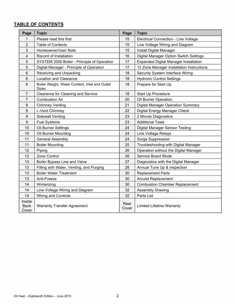
TABLE OF CONTENTS
Page Topic Page Topic
1 Please read this first 15 Electrical Connection - Line Voltage
2 Table of Contents 15 Low Voltage Wiring and Diagram
3 Homeowner/User Note 15 Install Digital Manager
4 Record of Installation 16 Digital Manager Option Switch Settings
5 SYSTEM 2000 Boiler - Principle of Operation 17 Expanded Digital Manager Installation
5 Digital Manager - Principle of Operation 17 12 Zone Manager Installation Instructions
6 Receiving and Unpacking 18 Security System Interface Wiring
6 Location and Clearance 18 Hydronic Control Settings
6 Boiler Weight, Water Content, Inlet and Outlet Sizes
18 Prepare for Start Up
7 Clearance for Cleaning and Service 18 Start Up Procedure
7 Combustion Air 20 Oil Burner Operation
8 Chimney Venting 21 Digital Manager Operation Summary
9 L-Vent Chimney 22 Digital Energy Manager Check
9 Sidewall Venting 23 2 Minute Diagnostics
9 Fuel Systems 23 Additional Tests
10 Oil Burner Settings 24 Digital Manager Sensor Testing
10 Oil Burner Mounting 24 Line Voltage Relays
11 General Assembly 24 Surge Suppression
11 Boiler Mounting 25 Troubleshooting with Digital Manager
12 Piping 26 Operation without the Digital Manager
12 Zone Control 26 Service Board Mode
13 Boiler Bypass Line and Valve 27 Diagnostics with the Digital Manager
13 Filling with Water, Venting, and Purging 28 Annual Tune Up & Inspection
13 Boiler Water Treatment 30 Replacement Parts
13 Anti-Freeze 30 Amulet Replacement
14 Winterizing 30 Combustion Chamber Replacement
14 Line Voltage Wiring and Diagram 32 Assembly Drawing
14 Wiring and Controls 32 Parts List
Inside Back Cover
Warranty Transfer Agreement Rear Cover
Limited Lifetime Warranty
Oil Heat – Eighteenth Edition – June 2015 3
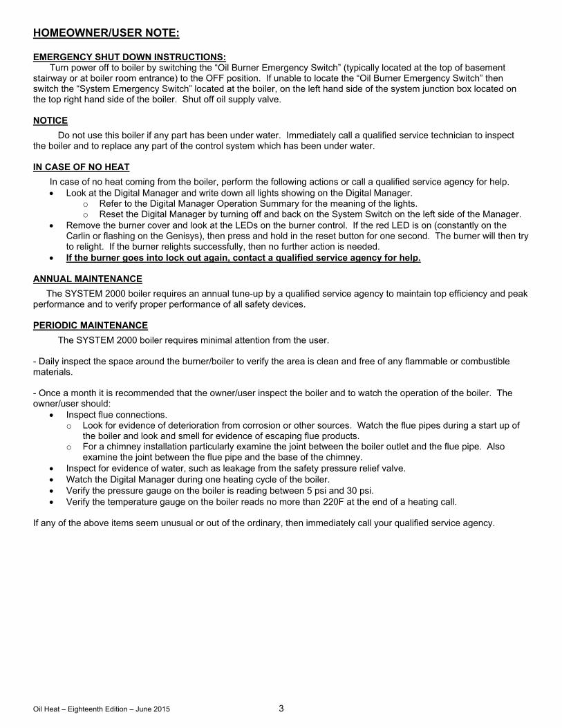
HOMEOWNER/USER NOTE: EMERGENCY SHUT DOWN INSTRUCTIONS:
Turn power off to boiler by switching the “Oil Burner Emergency Switch” (typically located at the top of basement stairway or at boiler room entrance) to the OFF position. If unable to locate the “Oil Burner Emergency Switch” then switch the “System Emergency Switch” located at the boiler, on the left hand side of the system junction box located on the top right hand side of the boiler. Shut off oil supply valve. NOTICE
Do not use this boiler if any part has been under water. Immediately call a qualified service technician to inspect the boiler and to replace any part of the control system which has been under water. IN CASE OF NO HEAT
In case of no heat coming from the boiler, perform the following actions or call a qualified service agency for help. Look at the Digital Manager and write down all lights showing on the Digital Manager.
o Refer to the Digital Manager Operation Summary for the meaning of the lights. o Reset the Digital Manager by turning off and back on the System Switch on the left side of the Manager.
Remove the burner cover and look at the LEDs on the burner control. If the red LED is on (constantly on the Carlin or flashing on the Genisys), then press and hold in the reset button for one second. The burner will then try to relight. If the burner relights successfully, then no further action is needed.
If the burner goes into lock out again, contact a qualified service agency for help. ANNUAL MAINTENANCE
The SYSTEM 2000 boiler requires an annual tune-up by a qualified service agency to maintain top efficiency and peak performance and to verify proper performance of all safety devices. PERIODIC MAINTENANCE
The SYSTEM 2000 boiler requires minimal attention from the user. - Daily inspect the space around the burner/boiler to verify the area is clean and free of any flammable or combustible materials. - Once a month it is recommended that the owner/user inspect the boiler and to watch the operation of the boiler. The owner/user should:
Inspect flue connections. o Look for evidence of deterioration from corrosion or other sources. Watch the flue pipes during a start up of
the boiler and look and smell for evidence of escaping flue products. o For a chimney installation particularly examine the joint between the boiler outlet and the flue pipe. Also
examine the joint between the flue pipe and the base of the chimney. Inspect for evidence of water, such as leakage from the safety pressure relief valve. Watch the Digital Manager during one heating cycle of the boiler. Verify the pressure gauge on the boiler is reading between 5 psi and 30 psi. Verify the temperature gauge on the boiler reads no more than 220F at the end of a heating call.
If any of the above items seem unusual or out of the ordinary, then immediately call your qualified service agency.
Oil Heat – Eighteenth Edition – June 2015 4
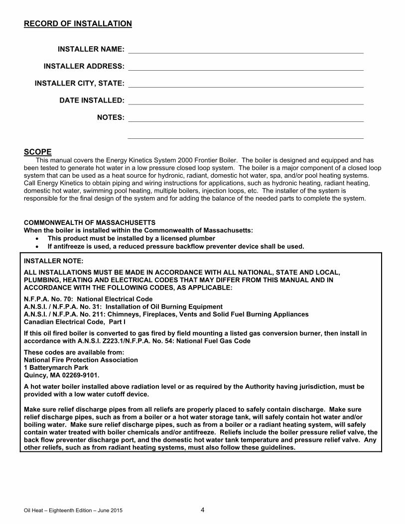
RECORD OF INSTALLATION
INSTALLER NAME:
INSTALLER ADDRESS:
INSTALLER CITY, STATE:
DATE INSTALLED:
NOTES:
SCOPE
This manual covers the Energy Kinetics System 2000 Frontier Boiler. The boiler is designed and equipped and has been tested to generate hot water in a low pressure closed loop system. The boiler is a major component of a closed loop system that can be used as a heat source for hydronic, radiant, domestic hot water, spa, and/or pool heating systems. Call Energy Kinetics to obtain piping and wiring instructions for applications, such as hydronic heating, radiant heating, domestic hot water, swimming pool heating, multiple boilers, injection loops, etc. The installer of the system is responsible for the final design of the system and for adding the balance of the needed parts to complete the system. COMMONWEALTH OF MASSACHUSETTS When the boiler is installed within the Commonwealth of Massachusetts:
This product must be installed by a licensed plumber If antifreeze is used, a reduced pressure backflow preventer device shall be used.
INSTALLER NOTE:
ALL INSTALLATIONS MUST BE MADE IN ACCORDANCE WITH ALL NATIONAL, STATE AND LOCAL, PLUMBING, HEATING AND ELECTRICAL CODES THAT MAY DIFFER FROM THIS MANUAL AND IN ACCORDANCE WITH THE FOLLOWING CODES, AS APPLICABLE:
N.F.P.A. No. 70: National Electrical Code A.N.S.I. / N.F.P.A. No. 31: Installation of Oil Burning Equipment A.N.S.I. / N.F.P.A. No. 211: Chimneys, Fireplaces, Vents and Solid Fuel Burning Appliances Canadian Electrical Code, Part I
If this oil fired boiler is converted to gas fired by field mounting a listed gas conversion burner, then install in accordance with A.N.S.I. Z223.1/N.F.P.A. No. 54: National Fuel Gas Code
These codes are available from: National Fire Protection Association 1 Batterymarch Park Quincy, MA 02269-9101.
A hot water boiler installed above radiation level or as required by the Authority having jurisdiction, must be provided with a low water cutoff device. Make sure relief discharge pipes from all reliefs are properly placed to safely contain discharge. Make sure relief discharge pipes, such as from a boiler or a hot water storage tank, will safely contain hot water and/or boiling water. Make sure relief discharge pipes, such as from a boiler or a radiant heating system, will safely contain water treated with boiler chemicals and/or antifreeze. Reliefs include the boiler pressure relief valve, the back flow preventer discharge port, and the domestic hot water tank temperature and pressure relief valve. Any other reliefs, such as from radiant heating systems, must also follow these guidelines.
Oil Heat – Eighteenth Edition – June 2015 5
SYSTEM 2000® FRONTIER BOILER IMPORTANT MESSAGE TO HOMEOWNER/USER: These instructions should be carefully read and kept for future
reference to gain the best performance from your System 2000 Frontier boiler.
CONGRATULATIONS ON YOUR PURCHASE OF THE SYSTEM 2000 BOILER with its highly efficient low mass hydronic heat exchanger, the Energy Converter. It is the product of years of engineering and advanced design, which brings together in a single system all elements needed to provide efficient home heat and hot water. This operation and maintenance information has been prepared so that you may better understand and use your Energy Kinetics Frontier Boiler and Heating System.
SYSTEM 2000 BOILER - PRINCIPLE OF OPERATION SYSTEM 2000 comprises a heat source, the energy converter, circulating water, and five (or more) zones controlled
by an electronic control, the Digital Manager.
The Boiler sits cold until a thermostat calls for heat. The Digital Manager receives the call for heat and turns on the main circulator and burner. Water circulates within the boiler as it warms up to operating temperature. When ready, the zone valves open and deliver heat to the zones calling for heat. When the thermostats are satisfied, the Digital Manager turns off the burner and enters the energy recovery stage. The circulator and zone valve stay energized to deliver the heat remaining in the boiler to your home or to the domestic hot water storage tank.
When energy recovery is complete and the Boiler has been cooled off, the Digital Manager turns off the system and waits for another thermostat (or tank aquastat) to call for heat. SYSTEM 2000 runs the burner only when you need heat and delivers that heat only where you need heat.
The System 2000 Energy Converter is the product of advanced thermal engineering. It is designed with two separate passageways, nearly 10 feet long, coiled around each other. Water travels along one passageway from your home toward the center of the unit and heated gases travel from the unit center toward the chimney. This is a “forced circulation counter-flow” design and it provides very efficient transfer of heat from the burning fuel to the circulating water. The superior insulation of the boiler minimizes heat losses to the surroundings, resulting in directing heat to your home in an efficient and quiet manner.
SYSTEM 2000 has an extremely high annual efficiency (over 99% of steady state) because it runs only when your home or hot water storage tank needs heat. Energy recovery is completed at the end of each heat call, virtually eliminating off cycle losses.
Your System 2000 holds a minimal quantity of water so it begins to supply heat in about 90 seconds. This rapid response means that your rooms can be heated quickly to temperature. The System 2000 EK1 Frontier can heat water up to 100,000 BTU’s per hour and the EK2 Frontier up to 200,000 BTU/hr.
A modern retention head oil burner fires into the center of System 2000 where a high temperature, light weight ceramic chamber provides ideal conditions for “near perfect” efficient, pollution-free combustion. Your System 2000 is tightly sealed so all products of combustion pass only to the chimney or sidewall vent.
The FRONTIER Boiler is designed with a hinged front cover that allows access to the inside of the boiler for inspection and cleaning. All access for service is from the front, so the FRONTIER Boiler can be placed directly against a wall or into a closet.
DIGITAL MANAGER - PRINCIPLE OF OPERATION The left side of the Manager is the input side, which provides 24-volt power supply and connections for thermostats.
The right side is the output side, which starts the burner, circulator, zone valves or zone circulators and the domestic hot water circulator. See photo of the Manager on the cover.
Lights on the Digital Manager indicate what is calling for heat (left side) and (right side) lights indicate active zone(s), burner operation and circulator operation. These function lights are an aid in servicing. The following is a typical cycle.
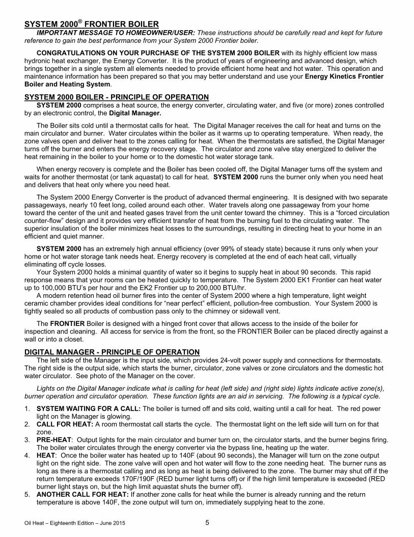
1. SYSTEM WAITING FOR A CALL: The boiler is turned off and sits cold, waiting until a call for heat. The red power light on the Manager is glowing.
2. CALL FOR HEAT: A room thermostat call starts the cycle. The thermostat light on the left side will turn on for that zone.
3. PRE-HEAT: Output lights for the main circulator and burner turn on, the circulator starts, and the burner begins firing. The boiler water circulates through the energy converter via the bypass line, heating up the water.
4. HEAT: Once the boiler water has heated up to 140F (about 90 seconds), the Manager will turn on the zone output light on the right side. The zone valve will open and hot water will flow to the zone needing heat. The burner runs as long as there is a thermostat calling and as long as heat is being delivered to the zone. The burner may shut off if the return temperature exceeds 170F/190F (RED burner light turns off) or if the high limit temperature is exceeded (RED burner light stays on, but the high limit aquastat shuts the burner off).
5. ANOTHER CALL FOR HEAT: If another zone calls for heat while the burner is already running and the return temperature is above 140F, the zone output will turn on, immediately supplying heat to the zone.
Oil Heat – Eighteenth Edition – June 2015 6
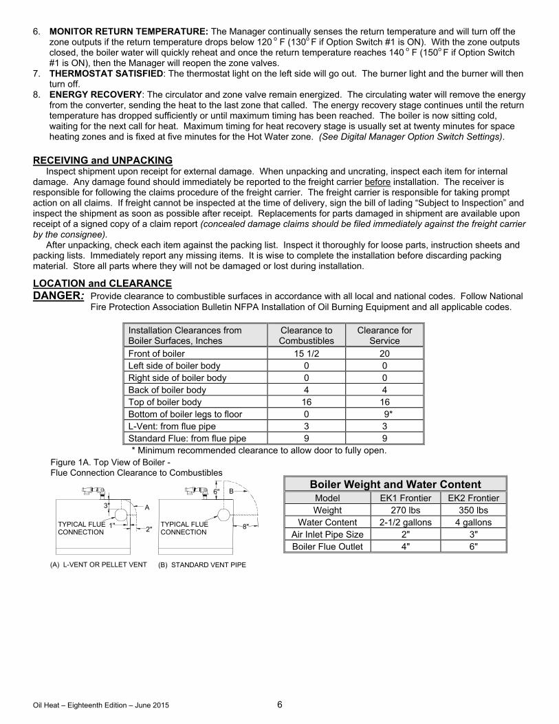
Figure 1A. Top View of Boiler - Flue Connection Clearance to Combustibles
B6"
(B) STANDARD VENT PIPE
TYPICAL FLUE CONNECTION
8"2"1"
A
TYPICAL FLUE CONNECTION
3"
(A) L-VENT OR PELLET VENT
6. MONITOR RETURN TEMPERATURE: The Manager continually senses the return temperature and will turn off the zone outputs if the return temperature drops below 120 o F (130o F if Option Switch #1 is ON). With the zone outputs closed, the boiler water will quickly reheat and once the return temperature reaches 140 o F (150o F if Option Switch #1 is ON), then the Manager will reopen the zone valves.
7. THERMOSTAT SATISFIED: The thermostat light on the left side will go out. The burner light and the burner will then turn off.
8. ENERGY RECOVERY: The circulator and zone valve remain energized. The circulating water will remove the energy from the converter, sending the heat to the last zone that called. The energy recovery stage continues until the return temperature has dropped sufficiently or until maximum timing has been reached. The boiler is now sitting cold, waiting for the next call for heat. Maximum timing for heat recovery stage is usually set at twenty minutes for space heating zones and is fixed at five minutes for the Hot Water zone. (See Digital Manager Option Switch Settings).
RECEIVING and UNPACKING Inspect shipment upon receipt for external damage. When unpacking and uncrating, inspect each item for internal damage. Any damage found should immediately be reported to the freight carrier before installation. The receiver is responsible for following the claims procedure of the freight carrier. The freight carrier is responsible for taking prompt action on all claims. If freight cannot be inspected at the time of delivery, sign the bill of lading “Subject to Inspection” and inspect the shipment as soon as possible after receipt. Replacements for parts damaged in shipment are available upon receipt of a signed copy of a claim report (concealed damage claims should be filed immediately against the freight carrier by the consignee). After unpacking, check each item against the packing list. Inspect it thoroughly for loose parts, instruction sheets and packing lists. Immediately report any missing items. It is wise to complete the installation before discarding packing material. Store all parts where they will not be damaged or lost during installation.
LOCATION and CLEARANCE DANGER: Provide clearance to combustible surfaces in accordance with all local and national codes. Follow National
Fire Protection Association Bulletin NFPA Installation of Oil Burning Equipment and all applicable codes.
Installation Clearances from Boiler Surfaces, Inches
Clearance to Combustibles
Clearance for Service
Front of boiler 15 1/2 20 Left side of boiler body 0 0 Right side of boiler body 0 0 Back of boiler body 4 4 Top of boiler body 16 16 Bottom of boiler legs to floor 0 9* L-Vent: from flue pipe 3 3 Standard Flue: from flue pipe 9 9 * Minimum recommended clearance to allow door to fully open.
Boiler Weight and Water Content Model EK1 Frontier EK2 Frontier Weight 270 lbs 350 lbs
Water Content 2-1/2 gallons 4 gallons Air Inlet Pipe Size 2" 3" Boiler Flue Outlet 4" 6"
Oil Heat – Eighteenth Edition – June 2015 7
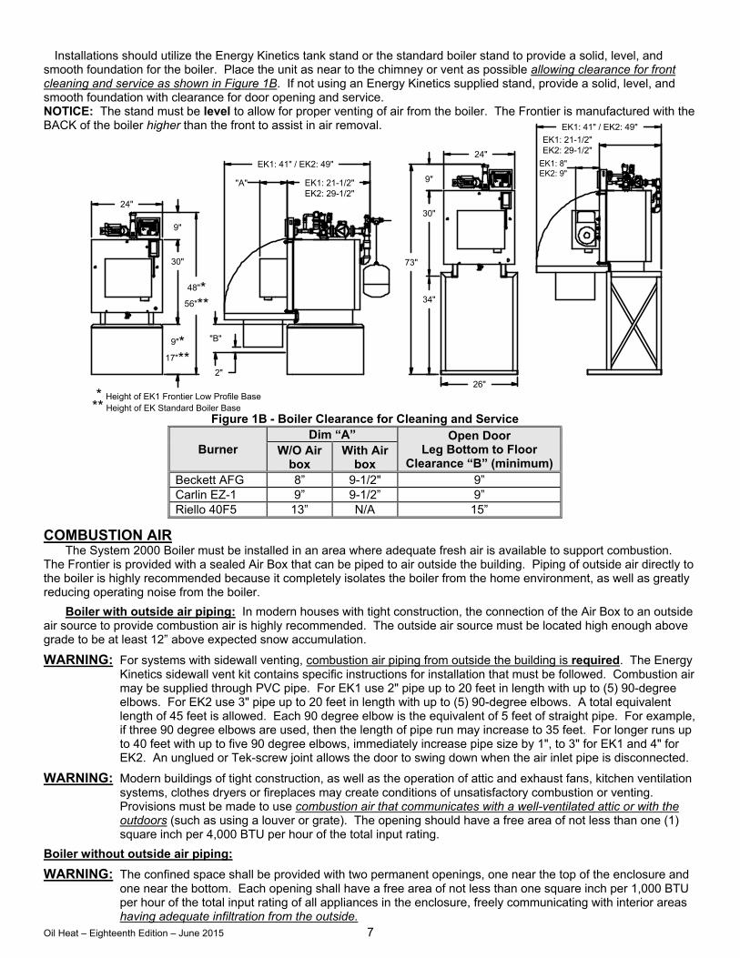
Installations should utilize the Energy Kinetics tank stand or the standard boiler stand to provide a solid, level, and
smooth foundation for the boiler. Place the unit as near to the chimney or vent as possible allowing clearance for front cleaning and service as shown in Figure 1B. If not using an Energy Kinetics supplied stand, provide a solid, level, and smooth foundation with clearance for door opening and service. NOTICE: The stand must be level to allow for proper venting of air from the boiler. The Frontier is manufactured with the BACK of the boiler higher than the front to assist in air removal.
Figure 1B - Boiler Clearance for Cleaning and Service
Burner Dim “A” Open Door
Leg Bottom to Floor Clearance “B” (minimum)
W/O Air box
With Air box
Beckett AFG 8” 9-1/2" 9” Carlin EZ-1 9” 9-1/2” 9” Riello 40F5 13” N/A 15”
COMBUSTION AIR The System 2000 Boiler must be installed in an area where adequate fresh air is available to support combustion.
The Frontier is provided with a sealed Air Box that can be piped to air outside the building. Piping of outside air directly to the boiler is highly recommended because it completely isolates the boiler from the home environment, as well as greatly reducing operating noise from the boiler.
Boiler with outside air piping: In modern houses with tight construction, the connection of the Air Box to an outside air source to provide combustion air is highly recommended. The outside air source must be located high enough above grade to be at least 12” above expected snow accumulation.
WARNING: For systems with sidewall venting, combustion air piping from outside the building is required. The Energy Kinetics sidewall vent kit contains specific instructions for installation that must be followed. Combustion air may be supplied through PVC pipe. For EK1 use 2" pipe up to 20 feet in length with up to (5) 90-degree elbows. For EK2 use 3" pipe up to 20 feet in length with up to (5) 90-degree elbows. A total equivalent length of 45 feet is allowed. Each 90 degree elbow is the equivalent of 5 feet of straight pipe. For example, if three 90 degree elbows are used, then the length of pipe run may increase to 35 feet. For longer runs up to 40 feet with up to five 90 degree elbows, immediately increase pipe size by 1", to 3" for EK1 and 4" for EK2. An unglued or Tek-screw joint allows the door to swing down when the air inlet pipe is disconnected.
WARNING: Modern buildings of tight construction, as well as the operation of attic and exhaust fans, kitchen ventilation systems, clothes dryers or fireplaces may create conditions of unsatisfactory combustion or venting. Provisions must be made to use combustion air that communicates with a well-ventilated attic or with the outdoors (such as using a louver or grate). The opening should have a free area of not less than one (1) square inch per 4,000 BTU per hour of the total input rating.
Boiler without outside air piping:
WARNING: The confined space shall be provided with two permanent openings, one near the top of the enclosure and one near the bottom. Each opening shall have a free area of not less than one square inch per 1,000 BTU per hour of the total input rating of all appliances in the enclosure, freely communicating with interior areas having adequate infiltration from the outside.
T4
R
S
TE
MP
. SE
NS
.
B
120
ALARM
100
Z2
Z324VAC
Z4
Z1ZHW
CIRC
B2
B1
IND
3
INDUCERCHIM NEYLESSONLY
4
HEA TI NG
HOT WATER
2
1
1 4 0
1 3 0
CIRCU LATOR
P OW E R
1 7 0
1 5 0
1 6 0
1 9 0
B URNER
SYSTEM 2000ENERGY MANAGER
ETICS
MA KI NG A NY CO NNECTI ONSRE AD I NST RUCTI ONS B EF ORE
ERGY
Lebanon, New Jersey
3
4
THE RMOST AT
2
1
CAUTION
24 VA C CONNECTI ON ONLY .
KINEN
T3
A1A2
THW
T1T2
T4
R
S
TE
MP
. SE
NS
.
B
1 20
26"
48"*56"**
24"
9"
73"
30"
* Height of EK1 Frontier Low Profile Base** Height of EK Standard Boiler Base
9"*17"**
34"
30"
24"
9"
EK1: 41" / EK2: 49"
2"
"B"
EK1: 41" / EK2: 49"
"A" A LA R M
1 00
Z2
Z324VAC
Z4
Z1ZHW
CIRC
B2
B1
IND
3
IND UCERCHI M NE Y LE S SO NLY
4
HE AT ING
HOT WATER
2
1
1 40
1 30
C IR CULA TO R
P OW E R
1 70
1 50
1 60
1 90
BU RNEREK1: 21-1/2"EK2: 29-1/2"
EK1: 8"EK2: 9"
SYSTEM 2000ENERGY MANAGER
ETICS
MA K ING ANY CONNE CTI ONSRE A D I NS TRUCT IONS BE FORE
ERGY
Lebanon , New Jersey
3
4
T HERMOS TA T
2
1
C AU TION
2 4 VA C CONNE CT I ON ONLY .
KINEN
T3
A1A2
THWT1T2
EK1: 21-1/2"EK2: 29-1/2"
Oil Heat – Eighteenth Edition – June 2015 8
CHIMNEY VENTING DANGER: Improper chimney installation or operation may cause flue gas leakage and/or carbon monoxide leakage,
which may lead to severe injury or death. When connecting an Energy Kinetics System 2000 boiler to an existing chimney, be sure to follow all applicable local,
state, and national codes that may differ from this manual, and in accordance with the following codes, as applicable: NFPA No. 31: Installation of Oil Burning Equipment NFPA No. 211: Chimneys, Fireplaces, Vents and Solid Fuel Burning Appliances If this oil fired boiler is converted to gas fired by field mounting a listed gas conversion burner, then install in
accordance with ANSI Z223.1/NFPA No. 54: National Fuel Gas Code
In retrofit installations, have chimney thoroughly cleaned. Carefully inspect chimney, base of chimney, and liner prior
to installation of System 2000 Boiler. WARNING: Masonry chimneys must have a tile or metal liner. The liner must:
1) Extend above the masonry. 2) Have an insulating air gap, isolating the liner from the chimney, allowing for rapid heat-up and draft
establishment. 3) Be sealed at each joint to prevent air infiltration and damage from condensation.
NOTICE: Inspect Chimney and Chimney base after initial three months of heating season.
The installation of a chimney cap is recommended. The base of the chimney must always have a drop leg below the flue connector to allow scale and condensation to accumulate without blocking the flue pipe. Do not block the flue opening by inserting the flue connecter too deeply into the chimney.
Best Practice: If drop leg is in excess of 12 inches deep, backfill with loose gravel or sand to obtain a maximum of 12-inch depth. Use of fiberglass insulation to backfill the drop leg is also a practical method. All clean out doors should be closed, and if practical also sealed with silicone, to prevent cold air entry into chimney. Clean out doors that are sealed with silicone can still be opened every tune up to inspect and clean the drop leg, and then resealed with silicone for another year. Pay particular attention to clean out doors that are located out of doors.
CAUTION: If liner is not sound or if existing tile liner fails to contain intermittent condensation, or if excessive debris is found at the base of the chimney, then it is recommended to install a properly sized metal liner approved for use with oil heat appliances.
The metal liner diameter and length should be as recommended by the metal liner manufacturer. Corrugated metal liners should be at least 5" diameter for EK1 and 6" diameter for EK2. Energy Kinetics has 5” for EK1 and 6” for EK2 flexible metal chimney connectors available to be used between the boiler flue collar and the chimney. Call Energy Kinetics for details on metal liners.
Chimney connectors should be positioned to create the shortest possible run of flue pipe to the chimney. The overall horizontal length of flue piping should not exceed 15 feet. Long runs or low firing rates may require insulated flue pipe such as L-Vent or All-Fuels to keep the temperature at base of chimney adequate for draft and to prevent corrosion of piping and connectors.
Because the System 2000 boiler uses a power burner, the flue pipe may experience some positive pressure on start up. Energy Kinetics recommends that all pipe joints be sealed with high temperature silicone sealant to ensure passage of all combustion products to the chimney.
Normally, pitch horizontal flue pipe up toward chimney approximately ¼” per foot. For existing installations, it is permissible for the flue connection of the boiler to be higher than the chimney thimble, provided adequate draft is established.
If a minimum of -0.02” w.c. draft overfire is not present after sufficient burner run time to heat up the chimney, there is a problem that will need to be corrected. Call Energy Kinetics for help resolving draft problems. Under normal circumstances, there is NO need for a DRAFT REGULATOR and one should not be installed. Call Energy Kinetics with questions about flue pipe sizing.
WARNING: No solid fuel appliance or fireplace should be installed in a flue common with this heating appliance. The flue gas exit of the venting system must be at least three (3) feet above the point at which it passes through the roof and at least two (2) feet higher than any portion of a building within 10 feet horizontally of its location.
Oil Heat – Eighteenth Edition – June 2015 9
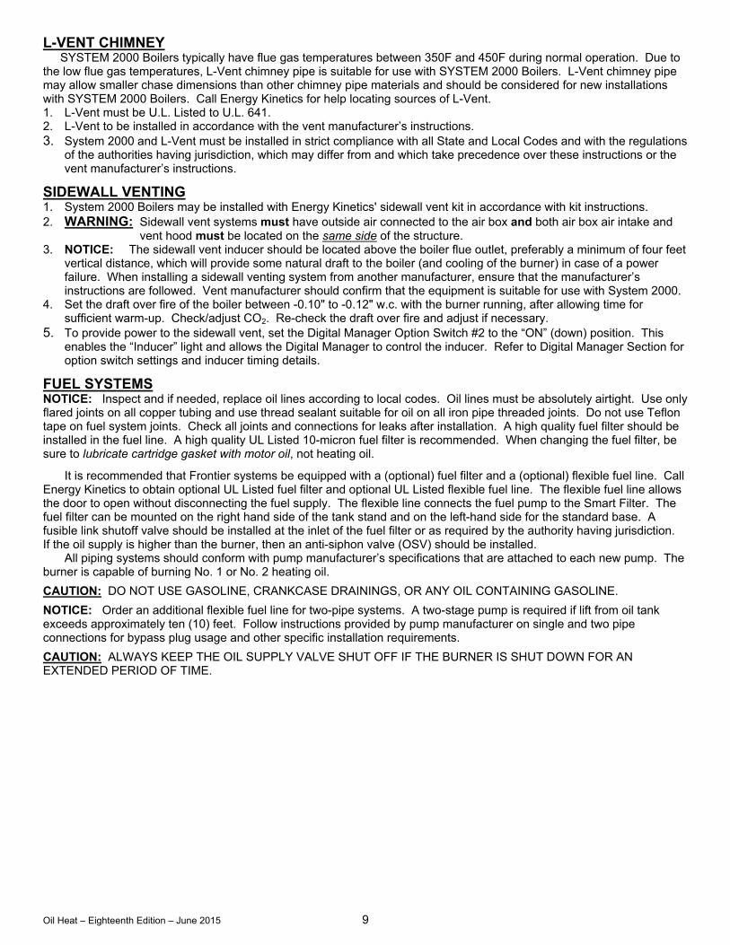
L-VENT CHIMNEY SYSTEM 2000 Boilers typically have flue gas temperatures between 350F and 450F during normal operation. Due to the low flue gas temperatures, L-Vent chimney pipe is suitable for use with SYSTEM 2000 Boilers. L-Vent chimney pipe may allow smaller chase dimensions than other chimney pipe materials and should be considered for new installations with SYSTEM 2000 Boilers. Call Energy Kinetics for help locating sources of L-Vent. 1. L-Vent must be U.L. Listed to U.L. 641. 2. L-Vent to be installed in accordance with the vent manufacturer’s instructions. 3. System 2000 and L-Vent must be installed in strict compliance with all State and Local Codes and with the regulations
of the authorities having jurisdiction, which may differ from and which take precedence over these instructions or the vent manufacturer’s instructions.
SIDEWALL VENTING 1. System 2000 Boilers may be installed with Energy Kinetics' sidewall vent kit in accordance with kit instructions. 2. WARNING: Sidewall vent systems must have outside air connected to the air box and both air box air intake and
vent hood must be located on the same side of the structure. 3. NOTICE: The sidewall vent inducer should be located above the boiler flue outlet, preferably a minimum of four feet
vertical distance, which will provide some natural draft to the boiler (and cooling of the burner) in case of a power failure. When installing a sidewall venting system from another manufacturer, ensure that the manufacturer’s instructions are followed. Vent manufacturer should confirm that the equipment is suitable for use with System 2000.
4. Set the draft over fire of the boiler between -0.10" to -0.12" w.c. with the burner running, after allowing time for sufficient warm-up. Check/adjust CO2. Re-check the draft over fire and adjust if necessary.
5. To provide power to the sidewall vent, set the Digital Manager Option Switch #2 to the “ON” (down) position. This enables the “Inducer” light and allows the Digital Manager to control the inducer. Refer to Digital Manager Section for option switch settings and inducer timing details.
FUEL SYSTEMS NOTICE: Inspect and if needed, replace oil lines according to local codes. Oil lines must be absolutely airtight. Use only flared joints on all copper tubing and use thread sealant suitable for oil on all iron pipe threaded joints. Do not use Teflon tape on fuel system joints. Check all joints and connections for leaks after installation. A high quality fuel filter should be installed in the fuel line. A high quality UL Listed 10-micron fuel filter is recommended. When changing the fuel filter, be sure to lubricate cartridge gasket with motor oil, not heating oil.
It is recommended that Frontier systems be equipped with a (optional) fuel filter and a (optional) flexible fuel line. Call Energy Kinetics to obtain optional UL Listed fuel filter and optional UL Listed flexible fuel line. The flexible fuel line allows the door to open without disconnecting the fuel supply. The flexible line connects the fuel pump to the Smart Filter. The fuel filter can be mounted on the right hand side of the tank stand and on the left-hand side for the standard base. A fusible link shutoff valve should be installed at the inlet of the fuel filter or as required by the authority having jurisdiction. If the oil supply is higher than the burner, then an anti-siphon valve (OSV) should be installed. All piping systems should conform with pump manufacturer’s specifications that are attached to each new pump. The burner is capable of burning No. 1 or No. 2 heating oil.
CAUTION: DO NOT USE GASOLINE, CRANKCASE DRAININGS, OR ANY OIL CONTAINING GASOLINE.
NOTICE: Order an additional flexible fuel line for two-pipe systems. A two-stage pump is required if lift from oil tank exceeds approximately ten (10) feet. Follow instructions provided by pump manufacturer on single and two pipe connections for bypass plug usage and other specific installation requirements.
CAUTION: ALWAYS KEEP THE OIL SUPPLY VALVE SHUT OFF IF THE BURNER IS SHUT DOWN FOR AN EXTENDED PERIOD OF TIME.
Oil Heat – Eighteenth Edition – June 2015 10
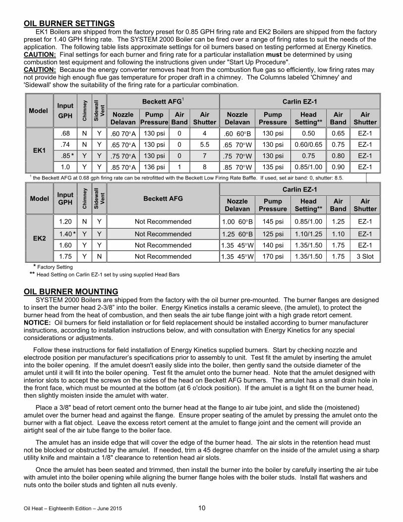
OIL BURNER SETTINGS EK1 Boilers are shipped from the factory preset for 0.85 GPH firing rate and EK2 Boilers are shipped from the factory preset for 1.40 GPH firing rate. The SYSTEM 2000 Boiler can be fired over a range of firing rates to suit the needs of the application. The following table lists approximate settings for oil burners based on testing performed at Energy Kinetics. CAUTION: Final settings for each burner and firing rate for a particular installation must be determined by using combustion test equipment and following the instructions given under "Start Up Procedure". CAUTION: Because the energy converter removes heat from the combustion flue gas so efficiently, low firing rates may not provide high enough flue gas temperature for proper draft in a chimney. The Columns labeled 'Chimney' and 'Sidewall' show the suitability of the firing rate for a particular combination.
Model Input
GPH
Ch
imn
ey
Sid
ewal
l V
ent Beckett AFG1 Carlin EZ-1
Nozzle Delavan
Pump Pressure
Air Band
Air Shutter
Nozzle Delavan
Pump Pressure
Head Setting**
Air Band
Air Shutter
EK1
.68 N Y .60 70A 130 psi 0 4 .60 60B 130 psi 0.50 0.65 EZ-1
.74 N Y .65 70A 130 psi 0 5.5 .65 70W 130 psi 0.60/0.65 0.75 EZ-1
.85 * Y Y .75 70A 130 psi 0 7 .75 70W 130 psi 0.75 0.80 EZ-1
1.0 Y Y .85 70A 136 psi 1 8 .85 70W 135 psi 0.85/1.00 0.90 EZ-1 1 the Beckett AFG at 0.68 gph firing rate can be retrofitted with the Beckett Low Firing Rate Baffle. If used, set air band: 0, shutter: 8.5.
Model Input GPH
Ch
imn
ey
Sid
ewal
l V
ent
Beckett AFG Carlin EZ-1
Nozzle Delavan
Pump Pressure
Head Setting**
Air Band
Air Shutter
EK2
1.20 N Y Not Recommended 1.00 60B 145 psi 0.85/1.00 1.25 EZ-1
1.40 * Y Y Not Recommended 1.25 60B 125 psi 1.10/1.25 1.10 EZ-1
1.60 Y Y Not Recommended 1.35 45W 140 psi 1.35/1.50 1.75 EZ-1
1.75 Y N Not Recommended 1.35 45W 170 psi 1.35/1.50 1.75 3 Slot
* Factory Setting
** Head Setting on Carlin EZ-1 set by using supplied Head Bars OIL BURNER MOUNTING
SYSTEM 2000 Boilers are shipped from the factory with the oil burner pre-mounted. The burner flanges are designed to insert the burner head 2-3/8” into the boiler. Energy Kinetics installs a ceramic sleeve, (the amulet), to protect the burner head from the heat of combustion, and then seals the air tube flange joint with a high grade retort cement. NOTICE: Oil burners for field installation or for field replacement should be installed according to burner manufacturer instructions, according to installation instructions below, and with consultation with Energy Kinetics for any special considerations or adjustments.
Follow these instructions for field installation of Energy Kinetics supplied burners. Start by checking nozzle and electrode position per manufacturer’s specifications prior to assembly to unit. Test fit the amulet by inserting the amulet into the boiler opening. If the amulet doesn't easily slide into the boiler, then gently sand the outside diameter of the amulet until it will fit into the boiler opening. Test fit the amulet onto the burner head. Note that the amulet designed with interior slots to accept the screws on the sides of the head on Beckett AFG burners. The amulet has a small drain hole in the front face, which must be mounted at the bottom (at 6 o'clock position). If the amulet is a tight fit on the burner head, then slightly moisten inside the amulet with water.
Place a 3/8" bead of retort cement onto the burner head at the flange to air tube joint, and slide the (moistened) amulet over the burner head and against the flange. Ensure proper seating of the amulet by pressing the amulet onto the burner with a flat object. Leave the excess retort cement at the amulet to flange joint and the cement will provide an airtight seal of the air tube flange to the boiler face.
The amulet has an inside edge that will cover the edge of the burner head. The air slots in the retention head must not be blocked or obstructed by the amulet. If needed, trim a 45 degree chamfer on the inside of the amulet using a sharp utility knife and maintain a 1/8" clearance to retention head air slots.
Once the amulet has been seated and trimmed, then install the burner into the boiler by carefully inserting the air tube with amulet into the boiler opening while aligning the burner flange holes with the boiler studs. Install flat washers and nuts onto the boiler studs and tighten all nuts evenly.
Oil Heat – Eighteenth Edition – June 2015 11
GENERAL ASSEMBLY Assembly of various packaged units is illustrated throughout this manual. The use of non-Energy Kinetics supplied pump, controls and accessories should follow good practices. The diagrams and locations presented in the manual are recommended.
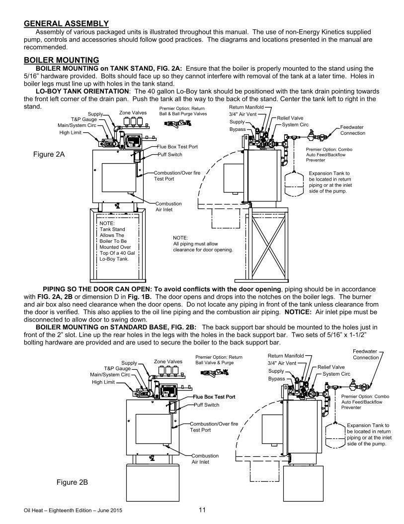
BOILER MOUNTING BOILER MOUNTING on TANK STAND, FIG. 2A: Ensure that the boiler is properly mounted to the stand using the
5/16” hardware provided. Bolts should face up so they cannot interfere with removal of the tank at a later time. Holes in boiler legs must line up with holes in the tank stand.
LO-BOY TANK ORIENTATION: The 40 gallon Lo-Boy tank should be positioned with the tank drain pointing towards the front left corner of the drain pan. Push the tank all the way to the back of the stand. Center the tank left to right in the stand.
PIPING SO THE DOOR CAN OPEN: To avoid conflicts with the door opening, piping should be in accordance
with FIG. 2A, 2B or dimension D in Fig. 1B. The door opens and drops into the notches on the boiler legs. The burner and air box also need clearance when the door opens. Do not locate any piping in front of the tank unless clearance from the door is verified. This also applies to the oil line piping and the combustion air piping. NOTICE: Air inlet pipe must be disconnected to allow door to swing down.
BOILER MOUNTING on STANDARD BASE, FIG. 2B: The back support bar should be mounted to the holes just in front of the 2” slot. Line up the rear holes in the legs with the holes in the back support bar. Two sets of 5/16” x 1-1/2” bolting hardware are provided and are used to secure the boiler to the back support bar.
Figure 2A
Supply
3/4" Air Vent
Bypass
Return Manifold
Relief ValveSystem Circ
Puff Switch
Flue Box Test Port
Combustion/Over fireTest Port
High Limit
Main/System Circ
SupplyT&P Gauge
CombustionAir Inlet
FeedwaterConnection
R
TE
MP
. SE
NS
.
T4
A1
B
S
A2
THW
T1T2
T3
B2
CIRC
ZHW
24VAC
Z3
IND
B1
Z1
Z2
Z4
Premier Option: ReturnBall & Ball Purge Valves
Premier Option: ComboAuto Feed/BackflowPreventer
NOTE:Tank StandAllows TheBoiler To BeMounted OverTop Of a 40 GalLo-Boy Tank.
Zone Valves
NOTE:All piping must allowclearance for door opening.
Expansion Tank tobe located in returnpiping or at the inletside of the pump.
Figure 2B
Supply
3/4" Air Vent
Bypass
Return Manifold
Relief ValveSystem Circ
Premier Option: ReturnBall Valve & Purge
Combustion/Over fireTest Port
CombustionAir Inlet
Flue Box Test Port
Puff Switch
SupplyT&P Gauge
Main/System Circ
High Limit
Zone Valves
Expansion Tank tobe located in returnpiping or at the inletside of the pump.
FeedwaterConnection
Flue Box Test Port24VAC
ZHW
CIRC
T3
A2
S
B
A1
T4
TE
MP
. SE
NS
.R
T2T1
THW
Z2
B1
IND
Z3
B2
Z4
Z1
Premier Option: ComboAuto Feed/BackflowPreventer
Oil Heat – Eighteenth Edition – June 2015 12
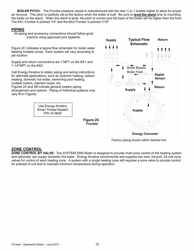
BOILER PITCH: The Frontier pressure vessel is manufactured with the rear ½ to 1 bubble higher to allow for proper air removal. This pitch is carefully set at the factory when the boiler is built. Be sure to level the stand prior to mounting the boiler on the stand. When the stand is level, the pitch is correct and the back of the boiler will be higher than the front. The EK1 Frontier is pitched 1/4" and the EK2 Frontier is pitched 7/16".
PIPING
All piping and accessory connections should follow good practice using approved joint sealants.
Figure 2C indicates a typical flow schematic for boiler water feeding multiple zones. Each system will vary according to job location. Supply and return connections are 1”NPT on the EK1 and 1-1/4”NPT on the EK2. Call Energy Kinetics to obtain piping and wiring instructions for alternate applications, such as hydronic heating, radiant heating, domestic hot water, swimming pool heating, multiple boilers, injection loops, etc. Figures 2A and 2B indicate general system piping arrangement and options. Piping of individual systems may vary from Figures. ZONE CONTROL ZONE CONTROL BY VALVE: The SYSTEM 2000 Boiler is designed to provide multi-zone control of the heating system and optionally can supply domestic hot water. Energy Kinetics recommends and supplies two wire, full port, 24-volt zone valves for control of each heating zone. A system with a single heating zone still requires a zone valve to provide control for preheat of unit and to maintain minimum temperature during operation.
Figure 2C Frontier
Use Energy Kinetics Smart Thread Sealant
P/N 10-0620 Supply
Return
ReturnSupply
Boiler Feed
Energy Converter
Typical FlowSchematic
Factory piping shown within dashed line
Supply
Boiler Bypass
DigitalSensor
Oil Heat – Eighteenth Edition – June 2015 13
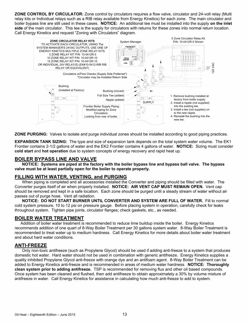
ZONE CONTROL BY CIRCULATOR: Zone control by circulators requires a flow valve, circulator and 24-volt relay (Multi relay kits or Individual relays such as a RIB relay available from Energy Kinetics) for each zone. The main circulator and boiler bypass line are still used in these cases. NOTICE: An additional tee must be installed into the supply on the inlet side of the main circulator. This tee is the supply for circulators with returns for these zones into normal return location. Call Energy Kinetics and request “Zoning with Circulators” diagram.
ZONE PURGING: Valves to isolate and purge individual zones should be installed according to good piping practices.
EXPANSION TANK SIZING: The type and size of expansion tank depends on the total system water volume. The EK1 Frontier contains 2-1/2 gallons of water and the EK2 Frontier contains 4 gallons of water. NOTICE: Sizing must consider cold start and hot operation due to system concepts of energy recovery and rapid heat up.
BOILER BYPASS LINE AND VALVE NOTICE: Systems are piped at the factory with the boiler bypass line and bypass ball valve. The bypass valve must be at least partially open for the boiler to operate properly.
FILLING WITH WATER, VENTING, and PURGING When piping is completed and all accessories installed the Converter and piping should be filled with water. The Converter purges itself of air when properly installed. NOTICE: AIR VENT CAP MUST REMAIN OPEN. Vent cap should be removed and kept in a safe location. Each zone should be purged until a steady stream of water without air passes out of purge hose. Vent all radiation. NOTICE: DO NOT START BURNER UNTIL CONVERTER AND SYSTEM ARE FULL OF WATER. Fill to normal cold system pressure, 10 to 12 psi on pressure gauge. Before placing system in operation, carefully check for leaks throughout system. Tighten pipe joints, circulator flanges; check gaskets, etc., as needed.
BOILER WATER TREATMENT Addition of boiler water treatment is recommended to reduce lime buildup inside the boiler. Energy Kinetics recommends addition of one quart of 8-Way Boiler Treatment per 30 gallons system water. 8-Way Boiler Treatment is recommended to treat water up to medium hardness. Call Energy Kinetics for more details about boiler water treatment and about hard water conditions.
ANTI-FREEZE Only non-toxic antifreeze (such as Propylene Glycol) should be used if adding anti-freeze to a system that produces domestic hot water. Hard water should not be used in combination with generic antifreeze. Energy Kinetics supplies a quality inhibited Propylene Glycol anti-freeze with orange dye and an antifoam agent. 8-Way Boiler Treatment can be added to Energy Kinetics anti-freeze and is recommended in areas of medium water hardness. NOTICE: Thoroughly clean system prior to adding antifreeze. TSP is recommended for removing flux and other oil based compounds. Once system has been cleaned and flushed, then add antifreeze to obtain approximately a 30% by volume mixture of antifreeze in water. Call Energy Kinetics for assistance in calculating how much anti-freeze to add to system.
Bushing
(Installed at Factory)
Full Size Tee (added)
Nipple (added)
Bushing (moved)
1. Remove bushing installed at factory from boiler supply.2. Install a nipple (not supplied) into the existing tee.3. Install a tee (not supplies) on to the new nipple.4. Reinstall the bushing into the new tee.
SUPPLY
THW
TE
MP
. SE
NS
.
T1T2
T3
A2
B
A1
S
R
T4
ZHW
Z1
Z2
24VAC
IND
Z3
B1
B2
CIRC
Z4
GroundNeutralLine
120
VA
C
Frontier Boiler Supply PipingModified piping for Zone
Circulators.Looking from rear of boiler.
Circulators w/Flow Checks (Supply Side Preferred*)*Circulator may be Installed Return Side
System Manager5 Zone Circulator Relay Kit
P/N: 10-0412R-5 ShownZONE CIRCULATOR RELAY KITSTO ACTIVATE EACH CIRCULATOR, USING The
SYSTEM MANAGER'S 24VAC OUTPUTS, USE ONE OFENERGY KINETICS MULTIPLE ZONE RELAY KITS.
5 ZONE RELAY KIT P/N: 10-0412R-510 ZONE RELAY KIT P/N: 10-0412R-1015 ZONE RELAY KIT P/N: 10-0412R-15
OR INDIVIDUAL 24V RELAY(S) (EK#10-0412-RIB RIBRELAY OR EQUIVALENT)
Oil Heat – Eighteenth Edition – June 2015 14
WINTERIZING NOTICE: If the SYSTEM 2000 Boiler may be exposed to freezing temperatures, such as a vacation home shut down for the winter, then anti-freeze should be added. When a home is winterized by draining all domestic water piping, then the SYSTEM 2000 Boiler must be protected. It is not recommended to drain the SYSTEM 2000 Boiler, because introducing air into the boiler can cause rusting inside the boiler shell and also because the Energy Converter has a spiral water passage that cannot be completely drained of water. When draining the domestic water piping system, be sure to drain the domestic side of the plate heat exchanger. If the hydronic system will not be drained, then add enough anti-freeze to protect the entire hydronic system including the boiler, piping, radiation, circulators, etc. If the hydronic system will be drained, then add shut off valves to isolate the boiler and add anti-freeze to the boiler only, as follows. Drain water from the boiler and then add anti-freeze to the boiler. Refill boiler with water and run boiler circulator through the bypass to distribute antifreeze within boiler. Propylene Glycol in water will provide the following freeze protection: 30% down to +8F, 40% to -8F, 50% to -27F. Energy Kinetics recommends using 30% anti-freeze to obtain the best boiler performance. Use over 30% anti-freeze only if lower temperature freeze protection is mandatory. Caution: Always keep the fuel supply valve shutoff if the burner is shut down for an extended period of time.
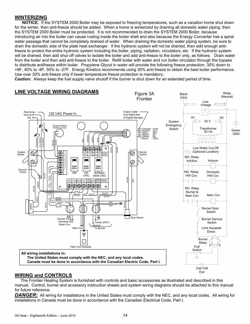
LINE VOLTAGE WIRING DIAGRAMS WIRING and CONTROLS The Frontier Heating System is furnished with controls and basic accessories as illustrated and described in this manual. Control, burner and accessory instruction sheets and system wiring diagrams should be attached to this manual for future reference. DANGER: All wiring for installations in the United States must comply with the NEC, and any local codes. All wiring for installations in Canada must be done in accordance with the Canadian Electrical Code, Part I.
TRANSFORMERPOWER LEADS
WHITEWHITE
WHITE
WHITE
BL
AC
KW
HIT
EOutle
t
BL
AC
K
GR
EE
NG
RE
EN
SwitchSystem
#14
WH
ITE
#1
4 G
RE
EN
WH
ITE
BL
AC
K
#1
4 B
LA
CK
Hot
NeutralGround
BL
AC
K
RED
BL
AC
K
Power (HOT)TT
To BurnerNeutral
Door Switch
BLACK
BLACKBLACK
RED
RE
D
BurnerSwitch
WH
ITE
RE
D
OR
AN
GE
BLA
CK
GR
EE
N
BL
UE
-24 V
-B2-B1-IND
-ZHW
-CIRC
(Green)
(Blue)(White)(Black)(Red)
(Orange)
120 VAC Power InB
LA
CK
BLA
CK
BLACK
BLACK
R
120VCIRCIND CIRCBURNGND PWRXFMR
LA
INDCIRCHW
HW MAIN
MAIN CIRCBURNER
24V1
V
TUEN
02
VACHWIND 24 CIRC
High Limit Aquastat
Main Circ
Domestic HotWater Circ
Inducer Fan
GroundScrew
Output Cablefrom Right Sideof Digital Manager
F F
SystemEmergency
Switch Transformer50 VA
Low Water Cut-Off(Optional Location)
NO. RelayInd/Aux Inducer
DomesticHW Circ
NO. RelayHW Circ
NO. RelayBurner &Main Circ Main Circ
Burner Service
Limit Aquastat
BurnerRelay
PuffSwitch
Cad CellEye
GNDGreen
(Neutral) WhiteBlack
(Hot)Line
Voltage
A124 V
A2
Switch
Burner DoorSwitch
Direct
Figure 3A Frontier
All wiring installations in: The United States must comply with the NEC, and any local codes. Canada must be done in accordance with the Canadian Electric Code, Part I.
Oil Heat – Eighteenth Edition – June 2015 15
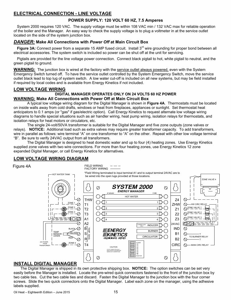
Figure 4A
ELECTRICAL CONNECTION - LINE VOLTAGE
POWER SUPPLY: 120 VOLT 60 HZ, 7.5 Amperes
System 2000 requires 120 VAC. The supply voltage must be within 108 VAC min / 132 VAC max for reliable operation of the boiler and the Manager. An easy way to check the supply voltage is to plug a voltmeter in at the service outlet located on the side of the system junction box.
DANGER: Make All Connections with Power Off at Main Circuit Box
Figure 3A: Connect power from a separate 15 AMP fused circuit. Install 3rd wire grounding for proper bond between all electrical accessories. The system switch is included so power can be shut off at the unit for servicing.
Pigtails are provided for the line voltage power connection. Connect black pigtail to hot, white pigtail to neutral, and the green pigtail to ground.
WARNING: The junction box is wired at the factory with the service outlet always powered, even with the System Emergency Switch turned off. To have the service outlet controlled by the System Emergency Switch, move the service outlet black lead to top lug of system switch. A low water cut-off is included on all new systems, but may be field installed if required by local codes and is available from Energy Kinetics if not included.
LOW VOLTAGE WIRING DIGITAL MANAGER OPERATES ONLY ON 24 VOLTS 60 HZ POWER
WARNING: Make All Connections with Power Off at Main Circuit Box
A typical low voltage wiring diagram for the Digital Manager is shown in Figure 4A. Thermostats must be located on inside walls away from cold drafts, windows or heat from fireplaces, appliances or sunlight. Set thermostat heat anticipators to 0.1 amps (or "gas" if gas/electric option). Call Energy Kinetics to request alternate low voltage wiring diagrams to handle special situations such as air handler wiring, heat pump wiring, isolation relays for thermostats, and isolation relays for heat motors or circulators, etc. The single 24-volt/50VA transformer is suitable for the Digital Manager and five zone outputs (zone valves or relays). NOTICE: Additional load such as extra valves may require greater transformer capacity. To add transformers, wire in parallel as follows: wire terminal “A” on one transformer to “A” on the other. Repeat with other low voltage terminal “B”. Be sure to verify 24VAC output from all transformers. The Digital Manager is designed to heat domestic water and up to four (4) heating zones. Use Energy Kinetics supplied zone valves with two wire connections. For more than four heating zones, use Energy Kinetics 12 zone expanded Digital Manager, or call Energy Kinetics for alternatives.
LOW VOLTAGE WIRING DIAGRAM INSTALL DIGITAL MANAGER
The Digital Manager is shipped in its own protective shipping box. NOTICE: The option switches can be set very easily before the Manager is installed. Locate the pre-wired quick connectors fastened to the front of the junction box by two cable ties. Cut the two cable ties and discard. Fasten the Digital Manager to the junction box with the four corner screws. Slide the two quick connectors onto the Digital Manager. Label each zone on the manager, using the adhesive labels supplied.
ZONE VALVE 3Z3A1
TRANSFORMER
24V POWER
RED
FROM ZONE 4
TEMP
LEADSSENSOR
BLACK
SILVER
TE
MP
. SE
NS
.
T4
R
CAUTION
MAKING ANY CONNECTIONSREAD INSTRUCTIONS BEFORE24 VAC CONNECTION ONLY.
B
S
A24
TO BURNER RELAY
MAIN CIRC RELAY
MONITOR
CIRCULATOR
160
130120100
140150
190POWER
170
ONLYCHIMNEYLESS
BURNER
INDUCER
4
CIRC
B2 T
IND
B1
24VAC
T
FIELD WIRINGFACTORY WIRING
ZONE 3
ZONE 1
ZONE 2
8070
60
90
THW
T2
T3
T12
3
1
HOT WATER TANK
HW CIRC RELAY
ZONE VALVE 2
ZONE VALVE 4
2
3
1
HOT WATER
Z4
Z1
Z2
ZHWZONE VALVE 1
*Field Wiring terminated to input terminal A1 and to output terminal 24VAC are to be wired into the open lugs provided at those locations.
Oil Heat – Eighteenth Edition – June 2015 16
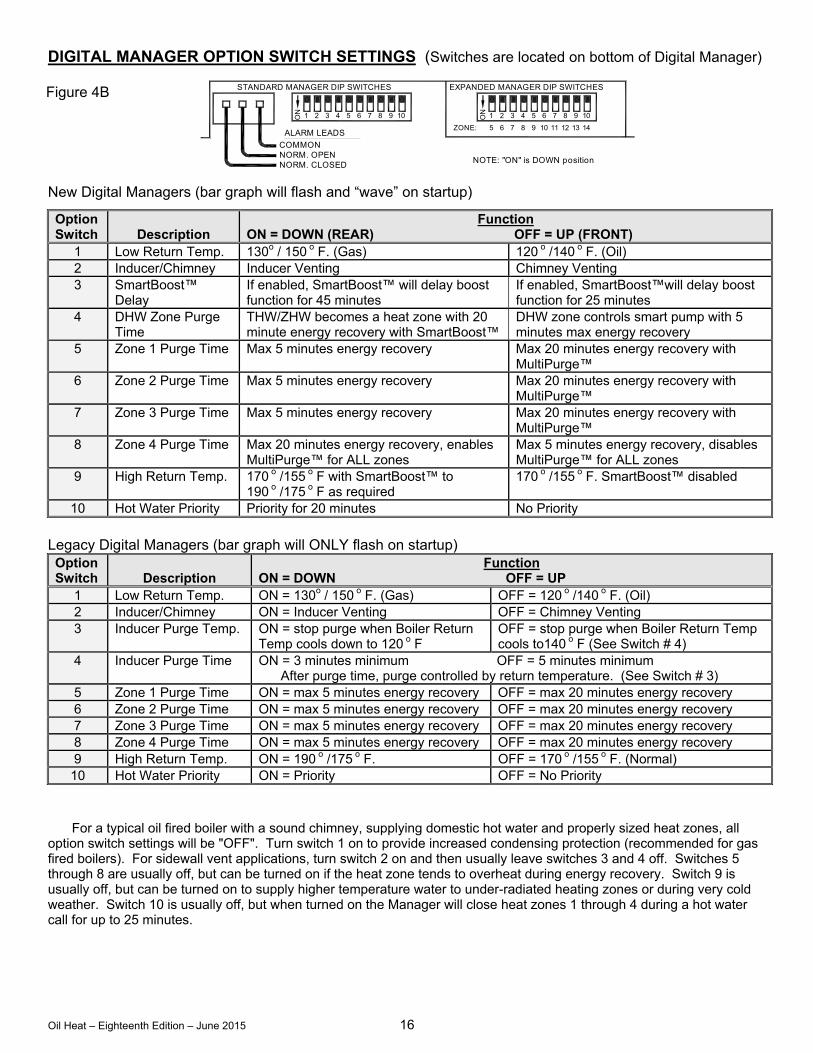
DIGITAL MANAGER OPTION SWITCH SETTINGS (Switches are located on bottom of Digital Manager) New Digital Managers (bar graph will flash and “wave” on startup)
Option Switch
Description
Function ON = DOWN (REAR) OFF = UP (FRONT)
1 Low Return Temp. 130o / 150 o F. (Gas) 120 o /140 o F. (Oil) 2 Inducer/Chimney Inducer Venting Chimney Venting 3 SmartBoost™
Delay If enabled, SmartBoost™ will delay boost function for 45 minutes
If enabled, SmartBoost™will delay boost function for 25 minutes
4 DHW Zone Purge Time
THW/ZHW becomes a heat zone with 20 minute energy recovery with SmartBoost™
DHW zone controls smart pump with 5 minutes max energy recovery
5 Zone 1 Purge Time Max 5 minutes energy recovery Max 20 minutes energy recovery with MultiPurge™
6 Zone 2 Purge Time Max 5 minutes energy recovery Max 20 minutes energy recovery with MultiPurge™
7 Zone 3 Purge Time Max 5 minutes energy recovery Max 20 minutes energy recovery with MultiPurge™
8 Zone 4 Purge Time Max 20 minutes energy recovery, enables MultiPurge™ for ALL zones
Max 5 minutes energy recovery, disables MultiPurge™ for ALL zones
9 High Return Temp. 170 o /155 o F with SmartBoost™ to 190 o /175 o F as required
170 o /155 o F. SmartBoost™ disabled
10 Hot Water Priority Priority for 20 minutes No Priority
Legacy Digital Managers (bar graph will ONLY flash on startup) Option Switch
Description
Function ON = DOWN OFF = UP
1 Low Return Temp. ON = 130o / 150 o F. (Gas) OFF = 120 o /140 o F. (Oil) 2 Inducer/Chimney ON = Inducer Venting OFF = Chimney Venting 3 Inducer Purge Temp. ON = stop purge when Boiler Return
Temp cools down to 120 o F OFF = stop purge when Boiler Return Temp cools to140 o F (See Switch # 4)
4 Inducer Purge Time ON = 3 minutes minimum OFF = 5 minutes minimum After purge time, purge controlled by return temperature. (See Switch # 3)
5 Zone 1 Purge Time ON = max 5 minutes energy recovery OFF = max 20 minutes energy recovery 6 Zone 2 Purge Time ON = max 5 minutes energy recovery OFF = max 20 minutes energy recovery 7 Zone 3 Purge Time ON = max 5 minutes energy recovery OFF = max 20 minutes energy recovery 8 Zone 4 Purge Time ON = max 5 minutes energy recovery OFF = max 20 minutes energy recovery 9 High Return Temp. ON = 190 o /175 o F. OFF = 170 o /155 o F. (Normal) 10 Hot Water Priority ON = Priority OFF = No Priority
For a typical oil fired boiler with a sound chimney, supplying domestic hot water and properly sized heat zones, all option switch settings will be "OFF". Turn switch 1 on to provide increased condensing protection (recommended for gas fired boilers). For sidewall vent applications, turn switch 2 on and then usually leave switches 3 and 4 off. Switches 5 through 8 are usually off, but can be turned on if the heat zone tends to overheat during energy recovery. Switch 9 is usually off, but can be turned on to supply higher temperature water to under-radiated heating zones or during very cold weather. Switch 10 is usually off, but when turned on the Manager will close heat zones 1 through 4 during a hot water call for up to 25 minutes.
Figure 4B EXPANDED MANAGER DIP SWITCHES
NOTE: "ON" is DOWN positionNORM. CLOSED
STANDARD MANAGER DIP SWITCHES
ALARM LEADS
NORM. OPENCOMMON
21ON 1 2 3 4ON019876543
ZONE: 8765
65 017 8 9
10 11 12 13 419
Oil Heat – Eighteenth Edition – June 2015 17
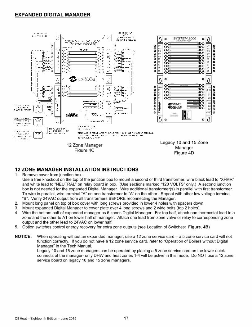
EXPANDED DIGITAL MANAGER
12 ZONE MANAGER INSTALLATION INSTRUCTIONS 1. Remove cover from junction box.
Use a free knockout on the top of the junction box to mount a second or third transformer, wire black lead to “XFMR” and white lead to “NEUTRAL” on relay board in box. (Use sections marked “120 VOLTS” only.) A second junction box is not needed for the expanded Digital Manager. Wire additional transformer(s) in parallel with first transformer. To wire in parallel, wire terminal “A” on one transformer to “A” on the other. Repeat with other low voltage terminal “B”. Verify 24VAC output from all transformers BEFORE reconnecting the Manager.
2. Mount long panel on top of box cover with long screws provided in lower 4 holes with spacers down. 3. Mount expanded Digital Manager to cover plate over 4 long screws and 2 wide bolts (top 2 holes). 4. Wire the bottom half of expanded manager as 5 zones Digital Manager. For top half, attach one thermostat lead to a
zone and the other to A1 on lower half of manager. Attach one lead from zone valve or relay to corresponding zone output and the other lead to 24VAC on lower half.
5. Option switches control energy recovery for extra zone outputs (see Location of Switches: Figure. 4B) NOTICE: When operating without an expanded manager, use a 12 zone service card – a 5 zone service card will not
function correctly. If you do not have a 12 zone service card, refer to “Operation of Boilers without Digital Manager” in the Tech Manual.
Legacy 10 and 15 zone managers can be operated by placing a 5 zone service card on the lower quick connects of the manager- only DHW and heat zones 1-4 will be active in this mode. Do NOT use a 12 zone service board on legacy 10 and 15 zone managers.
12 Zone Manager Figure 4C
Legacy 10 and 15 Zone Manager Figure 4D
T2
T4
A1T3
B
A2
S
R
TE
MP
. SE
NS
.
1010T10
THWT1
T7
T8
T6
T9
T5
7
5
6
8
9
7
5
6
8
9
THERMOSTAT
T13
T11
T14
T1211
12
14
13
11
12
14
13
HEATING
Z1
CIRC
IND
B2
B1
Z2Z3
24VAC
Z10
Z4ZHW
Z5
Z6
Z8
Z7
Z9
Z13Z12Z11
Z14
HEATING
INDUCER
BURNER
CIRCULATOR
140
MAKING ANY CONNECTIONSREAD INSTRUCTIONS BEFORE
MONITOR
120100
130
CHIMNEYLESS
CAUTION24 VAC CONNECTION ONLY.
190
160150
170
POWER
ONLY
4
3
2
1
HOT WATER
THERMOSTAT
4
3
2
1
Oil Heat – Eighteenth Edition – June 2015 18
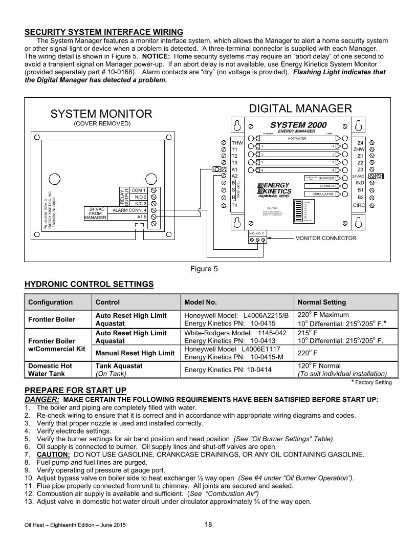
SECURITY SYSTEM INTERFACE WIRING
The System Manager features a monitor interface system, which allows the Manager to alert a home security system or other signal light or device when a problem is detected. A three-terminal connector is supplied with each Manager. The wiring detail is shown in Figure 5. NOTICE: Home security systems may require an “abort delay” of one second to avoid a transient signal on Manager power-up. If an abort delay is not available, use Energy Kinetics System Monitor (provided separately part # 10-0168). Alarm contacts are “dry” (no voltage is provided). Flashing Light indicates that the Digital Manager has detected a problem.
HYDRONIC CONTROL SETTINGS
Configuration Control Model No. Normal Setting
Frontier Boiler Auto Reset High Limit Aquastat
Honeywell Model: L4006A2215/B Energy Kinetics PN: 10-0415
220o F Maximum 10o Differential: 215o/205o F.*
Frontier Boiler w/Commercial Kit
Auto Reset High Limit Aquastat
White-Rodgers Model: 1145-042 Energy Kinetics PN: 10-0413
215o F 10o Differential: 215o/205o F.
Manual Reset High Limit Honeywell Model L4006E1117 Energy Kinetics PN: 10-0415-M
220o F
Domestic Hot Water Tank
Tank Aquastat (On Tank) Energy Kinetics PN: 10-0414 120o F Normal
(To suit individual installation)* Factory Setting
PREPARE FOR START UP DANGER: MAKE CERTAIN THE FOLLOWING REQUIREMENTS HAVE BEEN SATISFIED BEFORE START UP: 1. The boiler and piping are completely filled with water. 2. Re-check wiring to ensure that it is correct and in accordance with appropriate wiring diagrams and codes. 3. Verify that proper nozzle is used and installed correctly. 4. Verify electrode settings. 5. Verify the burner settings for air band position and head position (See "Oil Burner Settings" Table). 6. Oil supply is connected to burner. Oil supply lines and shut-off valves are open. 7. CAUTION: DO NOT USE GASOLINE, CRANKCASE DRAININGS, OR ANY OIL CONTAINING GASOLINE. 8. Fuel pump and fuel lines are purged. 9. Verify operating oil pressure at gauge port. 10. Adjust bypass valve on boiler side to heat exchanger ½ way open (See #4 under “Oil Burner Operation”). 11. Flue pipe properly connected from unit to chimney. All joints are secured and sealed. 12. Combustion air supply is available and sufficient. (See “Combustion Air”) 13. Adjust valve in domestic hot water circuit under circulator approximately ¾ of the way open.
N/C N/O C
A2
T4
S
R
BT
EM
P. S
EN
S.
T2
T3A1
THWT1 ZHW
IND
CIRC
24VAC
MONITOR CONNECTOR
POWER
CHIMNEYLESS
MONITOR
MAKING ANY CONNECTIONSREAD INSTRUCTIONS BEFORE24 VAC CONNECTION ONLY.
CAUTION
140130
100120
190
160150
170
2
4
3
1
HOT WATER
INDUCER
CIRCULATOR
BURNER
ONLY
B1
B2
2
4
3
1
Z1
Z3Z2
Z4
DIGITAL MANAGER
MANAGERFROM24 VAC
(COVER REMOVED)SYSTEM MONITOR
EN
ER
GY
KIN
ET
ICS
, IN
C.
PN
10-
016
8 R
EV
. 0
LE
BA
NO
N,
NJ
0883
3
ALARM CONN. 4
OU
TP
UT
RE
LA
Y
A1 5
N/O 2
COM 1
N/C 3
Figure 5
Oil Heat – Eighteenth Edition – June 2015 19
14. Punch a ¼” sampling hole in flue pipe as near to unit as possible in flue outlet for flue gas temperature and loosen 1/8” NPT hex plug in front jacket (to right of burner) for the over fire sampling location.
15. CAUTION: All covers, enclosures, and guards must be maintained in place at all times, except during maintenance and servicing.
16. CAUTION: Do not start burner unless the front door is closed and the nuts have been properly tightened.
START UP PROCEDURE 1. Turn on system supply switch and burner supply switch. The Digital Manager lights should come on briefly, the
circulator relay should close briefly, and then the Digital Manager should only show one red light next to 'power'. 2. The hot water tank aquastat should call for heat, if not, adjust a thermostat to call for heat. Burner and main circulator
should come on at the same time. If not, check primary control and reset it if necessary. 3. Check for burner light off. On an oil supply system with one pipe, it will be necessary to bleed air from fuel pump. On
a two pipe system, several starts may be required to clear air from fuel pump, or bleed air from pump. 4. On light off, water temperature and chimney temperature will start to rise. A slight odor is common on initial light off
as combustion chamber and converter surfaces warm for the first time. 5. NOTICE: Perform smoke test immediately after light off. Smoke test should show yellow after initial one minute of
operation due to the combustion chamber sizing heating up. If the smoke test shows dark grey or black after one minute of operation, shut off boiler immediately and repeat "Prepare for Start Up" checklist.
6. As Unit reaches temperature, Digital Manager “Heating” light will signal heat distribution to zone(s) calling for heat. (On first start up, this will usually be the hot water storage tank zone.) Once boiler water temperature reaches 160o – 180 o F., adjust hot water temperature flowing to storage tank. With hot water flowing fully from a domestic faucet, adjust valve under domestic circulator pump so water temperature going into tank is approximately 140 o F. (Hand can be held on pipe just briefly.) Water must be flowing fully from a household hot water tap to accurately adjust flow and temperature entering tank.
7. Allow system to run about 15 minutes before testing and recording burner operation. (See "Oil Burner Operation") 8. CAUTION: Do not attempt to start the burner when excess oil has accumulated, when the unit is full of vapor, or
when the combustion chamber is very hot. 9. CAUTION: NEVER BURN GARBAGE OR PAPER IN THE UNIT, AND NEVER LEAVE COMBUSTIBLE MATERIAL
AROUND IT.
Oil Heat – Eighteenth Edition – June 2015 20
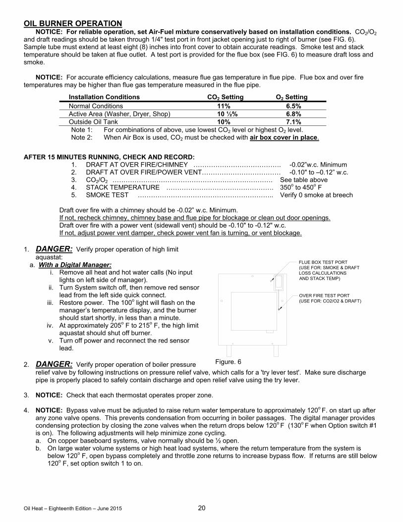
OIL BURNER OPERATION NOTICE: For reliable operation, set Air-Fuel mixture conservatively based on installation conditions. CO2/O2 and draft readings should be taken through 1/4" test port in front jacket opening just to right of burner (see FIG. 6). Sample tube must extend at least eight (8) inches into front cover to obtain accurate readings. Smoke test and stack temperature should be taken at flue outlet. A test port is provided for the flue box (see FIG. 6) to measure draft loss and smoke. NOTICE: For accurate efficiency calculations, measure flue gas temperature in flue pipe. Flue box and over fire temperatures may be higher than flue gas temperature measured in the flue pipe.
Installation Conditions CO2 Setting O2 Setting Normal Conditions 11% 6.5% Active Area (Washer, Dryer, Shop) 10 ½% 6.8% Outside Oil Tank 10% 7.1%
Note 1: For combinations of above, use lowest CO2 level or highest O2 level. Note 2: When Air Box is used, CO2 must be checked with air box cover in place.
AFTER 15 MINUTES RUNNING, CHECK AND RECORD: 1. DRAFT AT OVER FIRE/CHIMNEY …………………………………. -0.02”w.c. Minimum 2. DRAFT AT OVER FIRE/POWER VENT……………………………… -0.10" to –0.12” w.c.
3. CO2/O2 ………………………………………………………………. See table above 4. STACK TEMPERATURE …………………………………………. 350o to 450o F 5. SMOKE TEST …………………………………………………….. Verify 0 smoke at breech
Draft over fire with a chimney should be -0.02” w.c. Minimum. If not, recheck chimney, chimney base and flue pipe for blockage or clean out door openings. Draft over fire with a power vent (sidewall vent) should be -0.10" to -0.12" w.c. If not, adjust power vent damper, check power vent fan is turning, or vent blockage. 1. DANGER: Verify proper operation of high limit
aquastat: a. With a Digital Manager:
i. Remove all heat and hot water calls (No input lights on left side of manager).
ii. Turn System switch off, then remove red sensor lead from the left side quick connect.
iii. Restore power. The 100o light will flash on the manager’s temperature display, and the burner should start shortly, in less than a minute.
iv. At approximately 205o F to 215o F, the high limit aquastat should shut off burner.
v. Turn off power and reconnect the red sensor lead.
2. DANGER: Verify proper operation of boiler pressure
relief valve by following instructions on pressure relief valve, which calls for a 'try lever test'. Make sure discharge pipe is properly placed to safely contain discharge and open relief valve using the try lever.
3. NOTICE: Check that each thermostat operates proper zone. 4. NOTICE: Bypass valve must be adjusted to raise return water temperature to approximately 120o F. on start up after
any zone valve opens. This prevents condensation from occurring in boiler passages. The digital manager provides condensing protection by closing the zone valves when the return drops below 120o F (130o F when Option switch #1 is on). The following adjustments will help minimize zone cycling. a. On copper baseboard systems, valve normally should be ½ open. b. On large water volume systems or high heat load systems, where the return temperature from the system is
below 120o F, open bypass completely and throttle zone returns to increase bypass flow. If returns are still below 120o F, set option switch 1 to on.
OVER FIRE TEST PORT(USE FOR: CO2/O2 & DRAFT)
FLUE BOX TEST PORT(USE FOR: SMOKE & DRAFTLOSS CALCULATIONSAND STACK TEMP)
Figure. 6
Oil Heat – Eighteenth Edition – June 2015 21
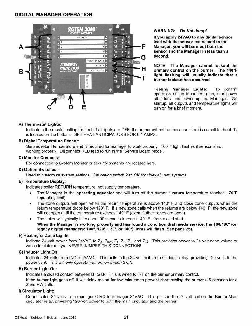
DIGITAL MANAGER OPERATION
WARNING: Do Not Jump!
If you apply 24VAC to any digital sensor lead with the sensor connected to the Manager, you will burn out both the sensor and the Manager in less than a second. NOTE: The Manager cannot lockout the primary control on the burner. The 140°F light flashing will usually indicate that a burner lockout has occurred. Testing Manager Lights: To confirm operation of the Manager lights, turn power off briefly and power up the Manager. On startup, all outputs and temperature lights will turn on for a brief moment.
A) Thermostat Lights: Indicate a thermostat calling for heat. If all lights are OFF, the burner will not run because there is no call for heat. T4
is located on the bottom. SET HEAT ANTICIPATORS FOR 0.1 AMPS.
B) Digital Temperature Sensor: Senses return temperature and is required for manager to work properly. 100°F light flashes if sensor is not working properly. Disconnect RED lead to run in the “Service Board Mode”.
C) Monitor Contacts: For connection to System Monitor or security systems are located here.
D) Option Switches: Used to customize system settings. Set option switch 2 to ON for sidewall vent systems.
E) Temperature Display: Indicates boiler RETURN temperature, not supply temperature.
The Manager is the operating aquastat and will turn off the burner if return temperature reaches 170°F (operating limit).
The zone outputs will open when the return temperature is above 140° F and close zone outputs when the return temperature drops below 120° F. If a new zone calls when the returns are below 140° F, the new zone will not open until the temperature exceeds 140° F (even if other zones are open).
The boiler will typically take about 90 seconds to reach 140° F from a cold start. When the Manager is working properly and has found a condition that needs service, the 100/190º (on legacy digital managers: 100º, 120º, 130º, or 140º) lights will flash (See page 25).
F) Heating or Zone Lights: Indicate 24-volt power from 24VAC to ZX (ZHW, Z1, Z2, Z3, and Z4). This provides power to 24-volt zone valves or zone circulator relays. NEVER JUMPER THIS CONNECTION!
G) Inducer Light On: Indicates 24 volts from IND to 24VAC. This pulls in the 24-volt coil on the inducer relay, providing 120-volts to the power vent. This will only operate with option switch 2 ON.
H) Burner Light On: Indicates a closed contact between B1 to B2. This is wired to T-T on the burner primary control. If the burner light goes off, it will delay restart for two minutes to prevent short-cycling the burner (45 seconds for a Zone HW call).
I) Circulator Light: On indicates 24 volts from manager CIRC to manager 24VAC. This pulls in the 24-volt coil on the Burner/Main circulator relay, providing 120-volt power to both the main circulator and the burner.
A
B
C D E
I
H
G
F
Oil Heat – Eighteenth Edition – June 2015 22
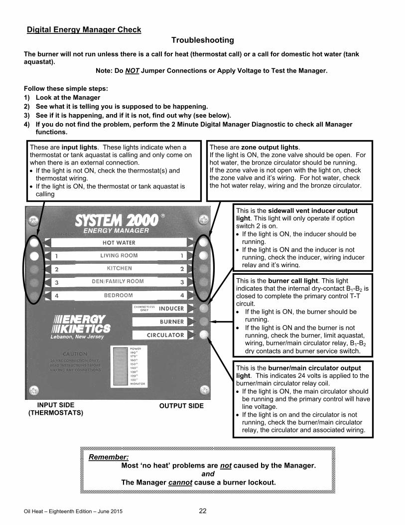
Digital Energy Manager Check Troubleshooting
The burner will not run unless there is a call for heat (thermostat call) or a call for domestic hot water (tank aquastat).
Note: Do NOT Jumper Connections or Apply Voltage to Test the Manager.
Follow these simple steps: 1) Look at the Manager 2) See what it is telling you is supposed to be happening. 3) See if it is happening, and if it is not, find out why (see below). 4) If you do not find the problem, perform the 2 Minute Digital Manager Diagnostic to check all Manager
functions.
These are input lights. These lights indicate when a thermostat or tank aquastat is calling and only come on when there is an external connection. If the light is not ON, check the thermostat(s) and
thermostat wiring. If the light is ON, the thermostat or tank aquastat is
calling
These are zone output lights. If the light is ON, the zone valve should be open. For hot water, the bronze circulator should be running. If the zone valve is not open with the light on, check the zone valve and it’s wiring. For hot water, check the hot water relay, wiring and the bronze circulator.
This is the sidewall vent inducer output light. This light will only operate if option switch 2 is on. If the light is ON, the inducer should be
running. If the light is ON and the inducer is not
running, check the inducer, wiring inducer relay and it’s wiring.
This is the burner call light. This light indicates that the internal dry-contact B1-B2 is closed to complete the primary control T-T circuit. If the light is ON, the burner should be
running. If the light is ON and the burner is not
running, check the burner, limit aquastat, wiring, burner/main circulator relay, B1-B2 dry contacts and burner service switch.
This is the burner/main circulator output light. This indicates 24 volts is applied to the burner/main circulator relay coil. If the light is ON, the main circulator should
be running and the primary control will have line voltage.
If the light is on and the circulator is not running, check the burner/main circulator relay, the circulator and associated wiring.
INPUT SIDE (THERMOSTATS)
OUTPUT SIDE
Remember: Most ‘no heat’ problems are not caused by the Manager.
and The Manager cannot cause a burner lockout.
Oil Heat – Eighteenth Edition – June 2015 23
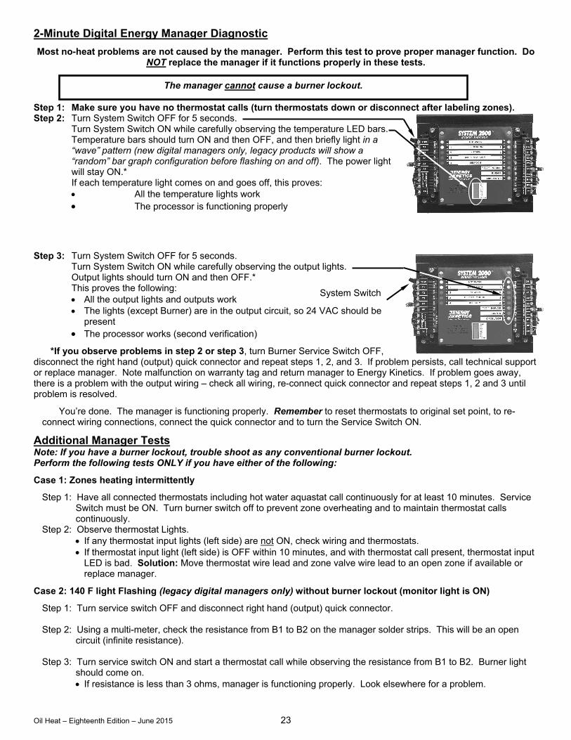
2-Minute Digital Energy Manager Diagnostic
Most no-heat problems are not caused by the manager. Perform this test to prove proper manager function. Do NOT replace the manager if it functions properly in these tests.
Step 1: Make sure you have no thermostat calls (turn thermostats down or disconnect after labeling zones). Step 2: Turn System Switch OFF for 5 seconds.
Turn System Switch ON while carefully observing the temperature LED bars. Temperature bars should turn ON and then OFF, and then briefly light in a “wave” pattern (new digital managers only, legacy products will show a “random” bar graph configuration before flashing on and off). The power light will stay ON.* If each temperature light comes on and goes off, this proves: All the temperature lights work The processor is functioning properly
Step 3: Turn System Switch OFF for 5 seconds.
Turn System Switch ON while carefully observing the output lights. Output lights should turn ON and then OFF.* This proves the following: All the output lights and outputs work The lights (except Burner) are in the output circuit, so 24 VAC should be
present The processor works (second verification)
*If you observe problems in step 2 or step 3, turn Burner Service Switch OFF, disconnect the right hand (output) quick connector and repeat steps 1, 2, and 3. If problem persists, call technical support or replace manager. Note malfunction on warranty tag and return manager to Energy Kinetics. If problem goes away, there is a problem with the output wiring – check all wiring, re-connect quick connector and repeat steps 1, 2 and 3 until problem is resolved.
You’re done. The manager is functioning properly. Remember to reset thermostats to original set point, to re-connect wiring connections, connect the quick connector and to turn the Service Switch ON.
Additional Manager Tests Note: If you have a burner lockout, trouble shoot as any conventional burner lockout. Perform the following tests ONLY if you have either of the following:
Case 1: Zones heating intermittently
Step 1: Have all connected thermostats including hot water aquastat call continuously for at least 10 minutes. Service Switch must be ON. Turn burner switch off to prevent zone overheating and to maintain thermostat calls continuously.
Step 2: Observe thermostat Lights. If any thermostat input lights (left side) are not ON, check wiring and thermostats. If thermostat input light (left side) is OFF within 10 minutes, and with thermostat call present, thermostat input
LED is bad. Solution: Move thermostat wire lead and zone valve wire lead to an open zone if available or replace manager.
Case 2: 140 F light Flashing (legacy digital managers only) without burner lockout (monitor light is ON)
Step 1: Turn service switch OFF and disconnect right hand (output) quick connector. Step 2: Using a multi-meter, check the resistance from B1 to B2 on the manager solder strips. This will be an open
circuit (infinite resistance). Step 3: Turn service switch ON and start a thermostat call while observing the resistance from B1 to B2. Burner light
should come on. If resistance is less than 3 ohms, manager is functioning properly. Look elsewhere for a problem.
The manager cannot cause a burner lockout.
System Switch
Oil Heat – Eighteenth Edition – June 2015 24
If resistance is greater than 3 ohms after 3 seconds of operation, B1-B2 contact is bad. Solution: Replace manager. Note: For 140F light flashing with a good B1-B2 manager relay (step 3 above), see “Trouble Shooting with the Digital Manager”.
Digital Manager Sensor Testing
The temperature sensor in the return line allows better boiler control, and virtually eliminates condensation caused by cold returns.
The temperature sensor is a mini computer chip sealed with epoxy inside a copper well. The chip communicates continuously with the Manager thousands of times a minute.
The Digital Manager is the tester of the digital temperature sensor. It verifies that it is connected and working properly.
The sensor cannot be tested with an ohm meter/volt meter or other device. Doing so could cause it to fail! The sensor operates on 5 volts DC. Never connect 24 volts to the black, silver or red sensor terminals
(labeled B, S, or R.) A caution: T4 thermostat input is adjacent to R, the red sensor terminal. When making thermostat
connections, never do so with power on. Once firm proper connections have been made, power up. We believe many sensors and Managers have been damaged by 24V being jumped or connected to B, S, or R.
Look carefully while making any connections to the Manager.
WARNING: Do Not Jump!
If you apply 24V to any digital sensor lead with the sensor connected to the Manager, you will burn out the sensor, the Manager or both in less than a second.
To test the functioning of each output zone, never apply a jumper to the Digital Manager output terminals. The easiest way to test each zone output is to remove the red sensor lead. The Manager should go into Service Board mode for 10 minutes, followed by Classic Manager mode. Adjust each thermostat to call for heat and the corresponding zone should come on if working properly.
Rule #1: Never use a jumper to test the function of the Digital Manager. Rule #2: Never use a jumper to test the function of the Digital Sensor. Rule #3: Never use a jumper to test the zones outputs. Rule #4: Only use a jumper from A1 to the thermostat inputs, if you can’t reach the thermostats. Rule #5: Always carry a Service Board with you.
Line Voltage Relays
Remember that behind the Manager is the junction box with the line voltage relays. The line voltage relays are controlled by the Manager.
The burner and circulator power is controlled by one line voltage relay. If both burner and circulator are without power, check the relay.
If the domestic hot water circulator does not have power, check the hot water relay. If equipped with an inducer and the inducer does not have power, check the inducer relay. Also check to be sure dip
switch #2 is turned “on”.
Line Voltage System 2000 requires 120 VAC. The supply voltage must be within 108 VAC min / 132 VAC max for reliable
operation of the boiler and the Manager. An easy way to check the supply voltage is to plug a volt meter in at the service outlet located on the system junction box.
Surge Suppression
The Relay Board located in the system junction box is equipped with built-in surge suppression on the 120VAC circuit. Older systems can be retrofitted using a plug-in surge suppressor.
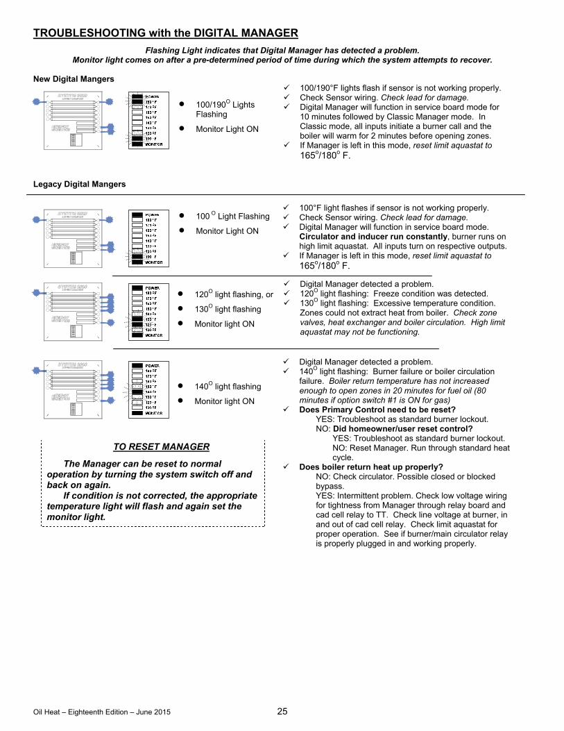
Oil Heat – Eighteenth Edition – June 2015 25
TROUBLESHOOTING with the DIGITAL MANAGER
Flashing Light indicates that Digital Manager has detected a problem. Monitor light comes on after a pre-determined period of time during which the system attempts to recover.
New Digital Mangers
Legacy Digital Mangers
120O light flashing, or 130O light flashing Monitor light ON
140O light flashing
Monitor light ON
100°F light flashes if sensor is not working properly. Check Sensor wiring. Check lead for damage. Digital Manager will function in service board mode.
Circulator and inducer run constantly, burner runs on high limit aquastat. All inputs turn on respective outputs.
If Manager is left in this mode, reset limit aquastat to 165o/180o F.
Digital Manager detected a problem. 140O light flashing: Burner failure or boiler circulation
failure. Boiler return temperature has not increased enough to open zones in 20 minutes for fuel oil (80 minutes if option switch #1 is ON for gas)
Does Primary Control need to be reset? YES: Troubleshoot as standard burner lockout. NO: Did homeowner/user reset control?
YES: Troubleshoot as standard burner lockout. NO: Reset Manager. Run through standard heat cycle.
Does boiler return heat up properly? NO: Check circulator. Possible closed or blocked bypass. YES: Intermittent problem. Check low voltage wiring for tightness from Manager through relay board and cad cell relay to TT. Check line voltage at burner, in and out of cad cell relay. Check limit aquastat for proper operation. See if burner/main circulator relay is properly plugged in and working properly.
Digital Manager detected a problem. 120O light flashing: Freeze condition was detected. 130O light flashing: Excessive temperature condition.
Zones could not extract heat from boiler. Check zone valves, heat exchanger and boiler circulation. High limit aquastat may not be functioning.
TO RESET MANAGER
The Manager can be reset to normal operation by turning the system switch off and back on again.
If condition is not corrected, the appropriate temperature light will flash and again set the monitor light.
100 O Light Flashing
Monitor Light ON
100/190O Lights Flashing
Monitor Light ON
100/190°F lights flash if sensor is not working properly. Check Sensor wiring. Check lead for damage. Digital Manager will function in service board mode for
10 minutes followed by Classic Manager mode. In Classic mode, all inputs initiate a burner call and the boiler will warm for 2 minutes before opening zones.
If Manager is left in this mode, reset limit aquastat to 165o/180o F.
Oil Heat – Eighteenth Edition – June 2015 26
OPERATION WITHOUT the DIGITAL MANAGER SERVICE BOARD MODE:
The Digital Manager can be placed into “SERVICE BOARD MODE” by turning off the system switch and removing the RED temperature sensor lead from the left side input connector, and turning power back on. Removing the RED lead does exactly the same thing as inserting the traditional green “Service Board”. The traditional service board may still be used if desired. SERVICE BOARD MODE allows the boiler to run like a conventional boiler. The burner is controlled by the high limit aquastat and the circulator runs continuously. If this mode is used, temporarily reset high limit aquastat to 165o/180o F.
TEMPORARY OPERATION WITH JUMPERS
(With partially functional Manager still in place and without service board) If a particular function of the Manager fails, use appropriate jumper action below with Manager in place.
BURNER: Jumper BB or TT on burner control. Burner will run on limit whenever Manager calls circulator. The boiler may overheat slightly during energy recovery. Temporarily reset limit aquastat to 165o/180o F.
MAIN CIRCULATOR: Remove blue CIRC lead from right side and connect to A2 on the left side, using an extension lead. The circulator will run constantly and the burner runs on Manager call.
ZONE/HOT WATER CONTROL: Remove zone valve and thermostat leads for zone. Connect a thermostat lead to A1. Connect a zone valve lead to A2. Wire the remaining thermostat and zone valve leads together. Zone valves will open whenever the Thermostat calls but it will not activate manager. If system is active, zone will receive heat when another calls or run system with high limit aquastat set to 165o/180o F and zone will get heat on call.
IF A PLUG-IN RELAY FAILS: Replace with spare relay. If spare is not available, temporarily install a relay with 24VAC coil and 120VAC contacts. Contact Energy Kinetics for connection details.
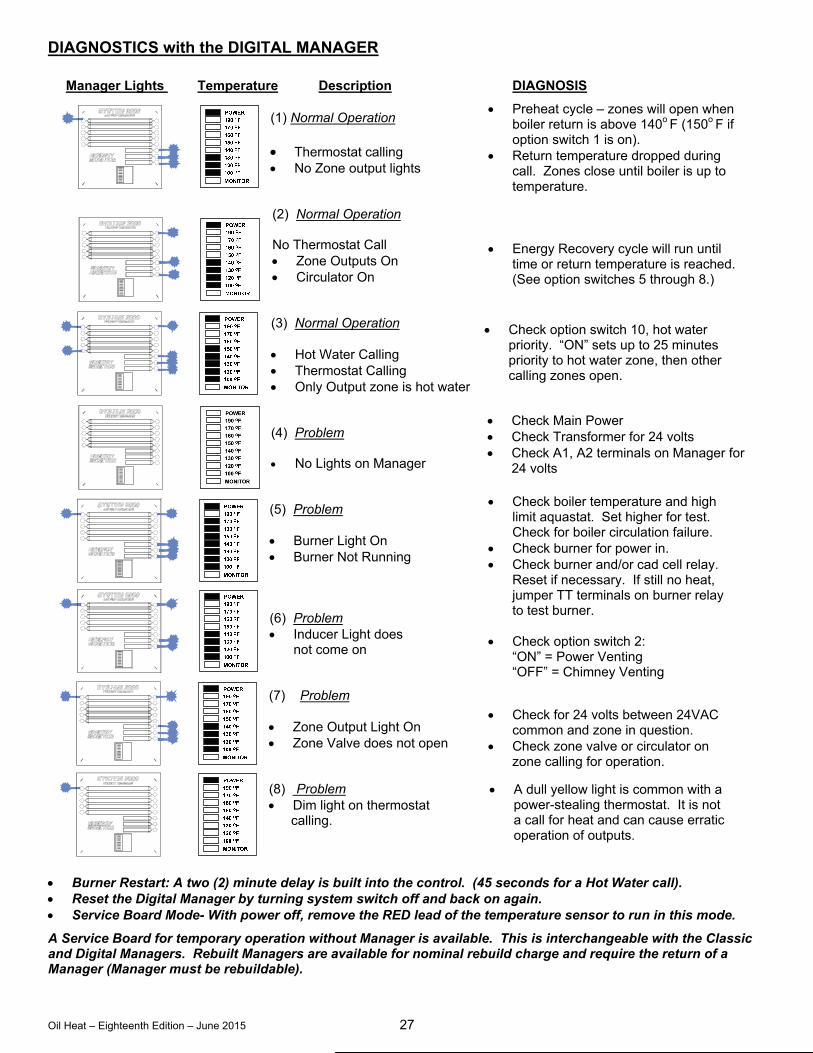
Oil Heat – Eighteenth Edition – June 2015 27
DIAGNOSTICS with the DIGITAL MANAGER
Manager Lights Temperature Description DIAGNOSIS (1) Normal Operation Thermostat calling No Zone output lights
(2) Normal Operation
No Thermostat Call Zone Outputs On Circulator On (3) Normal Operation Hot Water Calling Thermostat Calling Only Output zone is hot water (4) Problem No Lights on Manager (5) Problem Burner Light On Burner Not Running (6) Problem Inducer Light does
not come on (7) Problem Zone Output Light On Zone Valve does not open (8) Problem Dim light on thermostat calling.
Burner Restart: A two (2) minute delay is built into the control. (45 seconds for a Hot Water call). Reset the Digital Manager by turning system switch off and back on again. Service Board Mode- With power off, remove the RED lead of the temperature sensor to run in this mode.
A Service Board for temporary operation without Manager is available. This is interchangeable with the Classic and Digital Managers. Rebuilt Managers are available for nominal rebuild charge and require the return of a Manager (Manager must be rebuildable).
Preheat cycle – zones will open when boiler return is above 140o F (150o F if option switch 1 is on).
Return temperature dropped during call. Zones close until boiler is up to temperature.
Check Main Power Check Transformer for 24 volts Check A1, A2 terminals on Manager for
24 volts
Check boiler temperature and high limit aquastat. Set higher for test. Check for boiler circulation failure.
Check burner for power in. Check burner and/or cad cell relay.
Reset if necessary. If still no heat, jumper TT terminals on burner relay to test burner.
Check option switch 2: “ON” = Power Venting “OFF” = Chimney Venting
Check for 24 volts between 24VAC common and zone in question.
Check zone valve or circulator on zone calling for operation.
A dull yellow light is common with a power-stealing thermostat. It is not a call for heat and can cause erratic operation of outputs.
Check option switch 10, hot water priority. “ON” sets up to 25 minutes priority to hot water zone, then other calling zones open.
Energy Recovery cycle will run until time or return temperature is reached. (See option switches 5 through 8.)
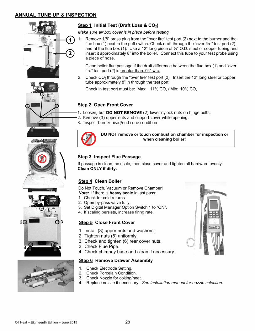
Oil Heat – Eighteenth Edition – June 2015 28
Step 2 Open Front Cover
1. Loosen, but DO NOT REMOVE (2) lower nylock nuts on hinge bolts. 2. Remove (3) upper nuts and support cover while opening. 3. Inspect burner head/end cone condition
ANNUAL TUNE UP & INSPECTION
Step 4 Clean Boiler
Do Not Touch, Vacuum or Remove Chamber! Note: If there is heavy scale in last pass: 1. Check for cold returns. 2. Open by-pass valve fully. 3. Set Digital Manager Option Switch 1 to “ON”. 4. If scaling persists, increase firing rate.
Step 1 Initial Test (Draft Loss & CO2)
Make sure air box cover is in place before testing
1. Remove 1/8” brass plug from the “over fire” test port (2) next to the burner and the flue box (1) next to the puff switch. Check draft through the “over fire” test port (2) and at the flue box (1). Use a 12” long piece of ¼” O.D. steel or copper tubing and insert it approximately 8” into the boiler. Connect this tube to your test probe using a piece of hose.
Clean boiler flue passage if the draft difference between the flue box (1) and “over fire” test port (2) is greater than .04” w.c.
2. Check CO2 through the “over fire” test port (2). Insert the 12” long steel or copper tube approximately 8” in through the test port.
Check in test port must be: Max: 11% CO2 / Min: 10% CO2
Step 6 Remove Drawer Assembly
1. Check Electrode Setting. 2. Check Porcelain Condition. 3. Check Nozzle for coking/heat. 4. Replace nozzle if necessary. See installation manual for nozzle selection.
1
2
Step 5 Close Front Cover
1. Install (3) upper nuts and washers. 2. Tighten nuts (5) uniformly. 3. Check and tighten (6) rear cover nuts. 3. Check Flue Pipe. 4. Check chimney base and clean if necessary.
Step 3 Inspect Flue Passage
If passage is clean, no scale, then close cover and tighten all hardware evenly. Clean ONLY if dirty.
DO NOT remove or touch combustion chamber for inspection or when cleaning boiler!
1
2 3
4 5
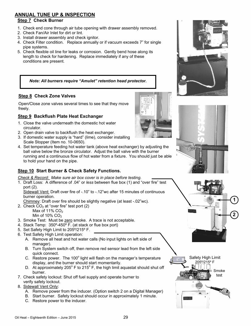
Oil Heat – Eighteenth Edition – June 2015 29
ANNUAL TUNE UP & INSPECTION
Step 10 Start Burner & Check Safety Functions.
Check & Record: Make sure air box cover is in place before testing. 1. Draft Loss: A difference of .04” or less between flue box (1) and “over fire” test
port (2). Sidewall Vent: Draft over fire of -.10” to -.12”wc after 15 minutes of continuous burner operation. Chimney: Draft over fire should be slightly negative (at least -.02”wc).
2. Check CO2 at “over fire” test port (2) Max of 11% CO2 Min of 10% CO2
3. Smoke Test: Must be zero smoke. A trace is not acceptable. 4. Stack Temp: 350º-450º F. (at stack or flue box port) 5. Set Safety High Limit to 205º/215º F. 6. Test Safety High Limit operation:
A. Remove all heat and hot water calls (No input lights on left side of manager).
B. Turn System switch off, then remove red sensor lead from the left side quick connect.
C. Restore power. The 100o light will flash on the manager’s temperature display, and the burner should start momentarily.
D. At approximately 205o F to 215o F, the high limit aquastat should shut off burner.
7. Check safety lockout: Shut off fuel supply and operate burner to verify safety lockout.
8. Sidewall Vent Only: A. Remove power from the inducer. (Option switch 2 on a Digital Manager) B. Start burner. Safety lockout should occur in approximately 1 minute. C. Restore power to the inducer.
Step 8 Check Zone Valves
Open/Close zone valves several times to see that they move freely.
Step 9 Backflush Plate Heat Exchanger
1. Close the valve underneath the domestic hot water circulator.
2. Open drain valve to backflush the heat exchanger. 3. If domestic water supply is “hard” (lime), consider installing
Scale Stopper (Item no. 10-0650). 4. Set temperature feeding hot water tank (above heat exchanger) by adjusting the
ball valve below the bronze circulator. Adjust the ball valve with the burner running and a continuous flow of hot water from a fixture. You should just be able to hold your hand on the pipe.
Step 7 Check Burner
1. Check end cone through air tube opening with drawer assembly removed. 2. Check Fan/Air Inlet for dirt or lint. 3. Install drawer assembly and check ignitor. 4. Check Filter condition. Replace annually or if vacuum exceeds 7” for single
pipe systems. 5. Check flexible oil line for leaks or corrosion. Gently bend hose along its
length to check for hardening. Replace immediately if any of these conditions are present.
Note: All burners require “Amulet” retention head protector.
1
2
Smoke test fl
Safety High Limit 205º/215º F
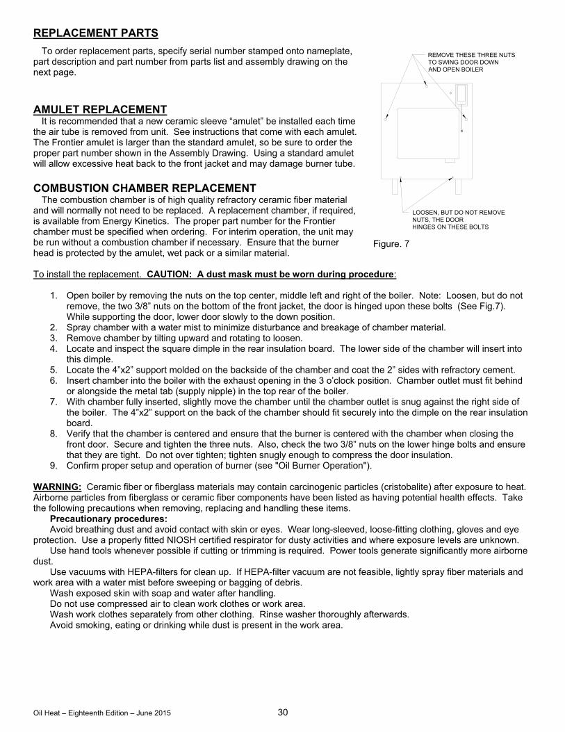
Oil Heat – Eighteenth Edition – June 2015 30
REPLACEMENT PARTS
To order replacement parts, specify serial number stamped onto nameplate, part description and part number from parts list and assembly drawing on the next page. AMULET REPLACEMENT It is recommended that a new ceramic sleeve “amulet” be installed each time the air tube is removed from unit. See instructions that come with each amulet. The Frontier amulet is larger than the standard amulet, so be sure to order the proper part number shown in the Assembly Drawing. Using a standard amulet will allow excessive heat back to the front jacket and may damage burner tube. COMBUSTION CHAMBER REPLACEMENT The combustion chamber is of high quality refractory ceramic fiber material and will normally not need to be replaced. A replacement chamber, if required, is available from Energy Kinetics. The proper part number for the Frontier chamber must be specified when ordering. For interim operation, the unit may be run without a combustion chamber if necessary. Ensure that the burner head is protected by the amulet, wet pack or a similar material. To install the replacement. CAUTION: A dust mask must be worn during procedure:
1. Open boiler by removing the nuts on the top center, middle left and right of the boiler. Note: Loosen, but do not remove, the two 3/8” nuts on the bottom of the front jacket, the door is hinged upon these bolts (See Fig.7). While supporting the door, lower door slowly to the down position.
2. Spray chamber with a water mist to minimize disturbance and breakage of chamber material. 3. Remove chamber by tilting upward and rotating to loosen. 4. Locate and inspect the square dimple in the rear insulation board. The lower side of the chamber will insert into
this dimple. 5. Locate the 4”x2” support molded on the backside of the chamber and coat the 2” sides with refractory cement. 6. Insert chamber into the boiler with the exhaust opening in the 3 o’clock position. Chamber outlet must fit behind
or alongside the metal tab (supply nipple) in the top rear of the boiler. 7. With chamber fully inserted, slightly move the chamber until the chamber outlet is snug against the right side of
the boiler. The 4”x2” support on the back of the chamber should fit securely into the dimple on the rear insulation board.
8. Verify that the chamber is centered and ensure that the burner is centered with the chamber when closing the front door. Secure and tighten the three nuts. Also, check the two 3/8” nuts on the lower hinge bolts and ensure that they are tight. Do not over tighten; tighten snugly enough to compress the door insulation.
9. Confirm proper setup and operation of burner (see "Oil Burner Operation"). WARNING: Ceramic fiber or fiberglass materials may contain carcinogenic particles (cristobalite) after exposure to heat. Airborne particles from fiberglass or ceramic fiber components have been listed as having potential health effects. Take the following precautions when removing, replacing and handling these items. Precautionary procedures: Avoid breathing dust and avoid contact with skin or eyes. Wear long-sleeved, loose-fitting clothing, gloves and eye protection. Use a properly fitted NIOSH certified respirator for dusty activities and where exposure levels are unknown. Use hand tools whenever possible if cutting or trimming is required. Power tools generate significantly more airborne dust. Use vacuums with HEPA-filters for clean up. If HEPA-filter vacuum are not feasible, lightly spray fiber materials and work area with a water mist before sweeping or bagging of debris. Wash exposed skin with soap and water after handling. Do not use compressed air to clean work clothes or work area. Wash work clothes separately from other clothing. Rinse washer thoroughly afterwards. Avoid smoking, eating or drinking while dust is present in the work area.
LOOSEN, BUT DO NOT REMOVENUTS, THE DOORHINGES ON THESE BOLTS
REMOVE THESE THREE NUTSTO SWING DOOR DOWNAND OPEN BOILER
Figure. 7
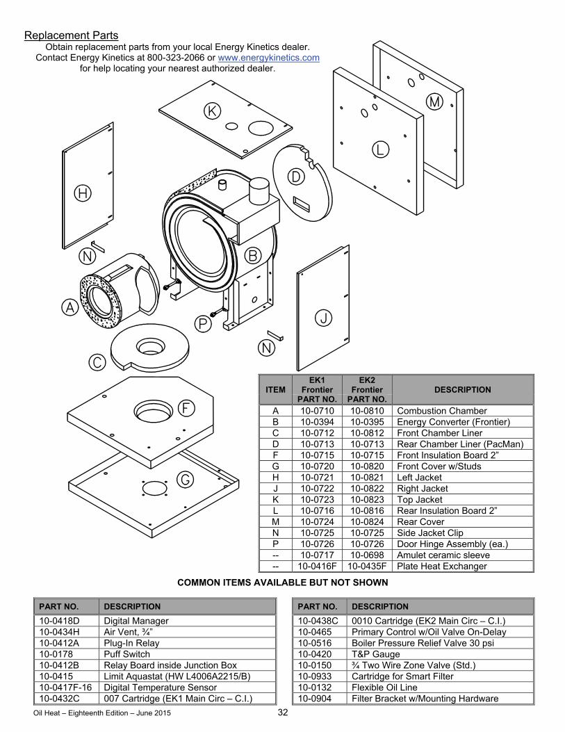
Oil Heat – Eighteenth Edition – June 2015 32
COMMON ITEMS AVAILABLE BUT NOT SHOWN
ITEM EK1
Frontier EK2
Frontier DESCRIPTION PART NO. PART NO.
A 10-0710 10-0810 Combustion Chamber B 10-0394 10-0395 Energy Converter (Frontier) C 10-0712 10-0812 Front Chamber Liner D 10-0713 10-0713 Rear Chamber Liner (PacMan) F 10-0715 10-0715 Front Insulation Board 2” G 10-0720 10-0820 Front Cover w/Studs H 10-0721 10-0821 Left Jacket J 10-0722 10-0822 Right Jacket K 10-0723 10-0823 Top Jacket L 10-0716 10-0816 Rear Insulation Board 2” M 10-0724 10-0824 Rear Cover N 10-0725 10-0725 Side Jacket Clip P 10-0726 10-0726 Door Hinge Assembly (ea.) -- 10-0717 10-0698 Amulet ceramic sleeve -- 10-0416F 10-0435F Plate Heat Exchanger
PART NO. DESCRIPTION PART NO. DESCRIPTION
10-0418D Digital Manager 10-0438C 0010 Cartridge (EK2 Main Circ – C.I.) 10-0434H Air Vent, ¾” 10-0465 Primary Control w/Oil Valve On-Delay 10-0412A Plug-In Relay 10-0516 Boiler Pressure Relief Valve 30 psi 10-0178 Puff Switch 10-0420 T&P Gauge 10-0412B Relay Board inside Junction Box 10-0150 ¾ Two Wire Zone Valve (Std.) 10-0415 Limit Aquastat (HW L4006A2215/B) 10-0933 Cartridge for Smart Filter 10-0417F-16 Digital Temperature Sensor 10-0132 Flexible Oil Line 10-0432C 007 Cartridge (EK1 Main Circ – C.I.) 10-0904 Filter Bracket w/Mounting Hardware
Replacement Parts Obtain replacement parts from your local Energy Kinetics dealer.
Contact Energy Kinetics at 800-323-2066 or www.energykinetics.com for help locating your nearest authorized dealer.
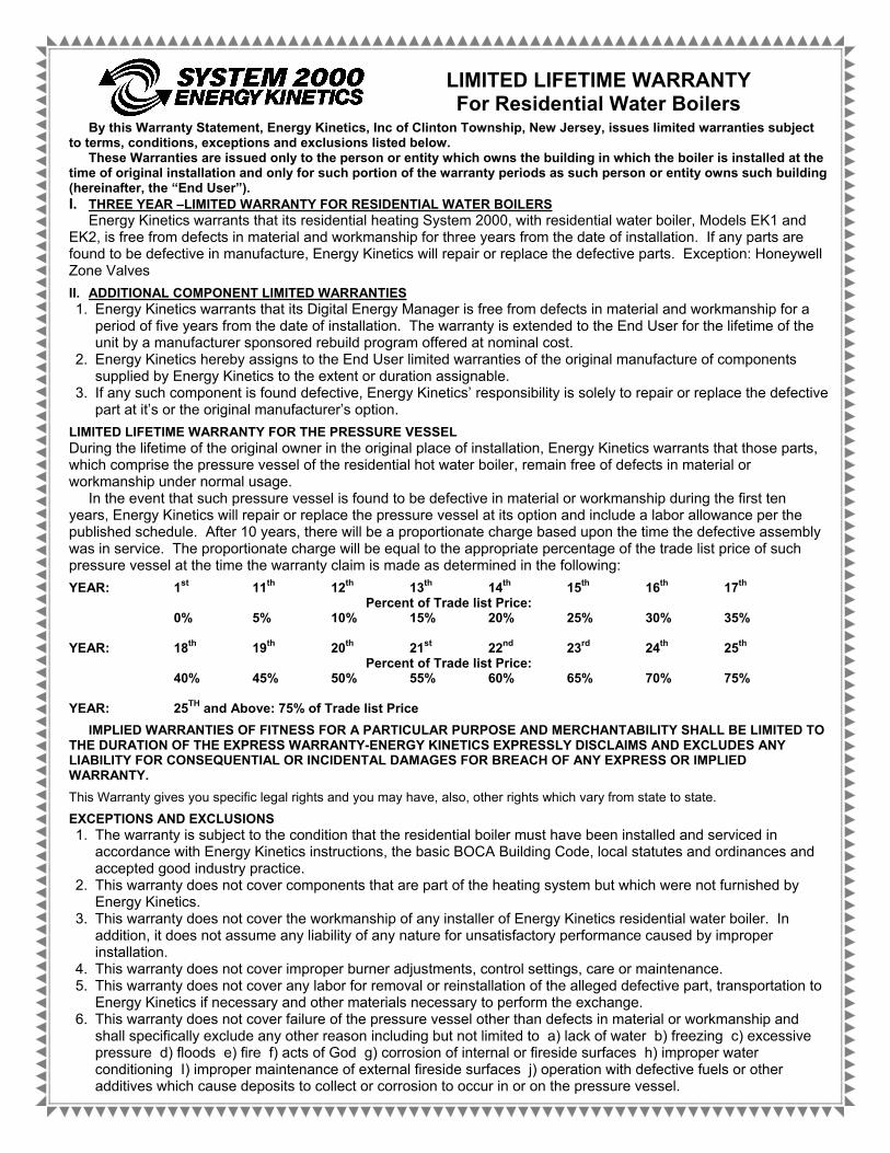
Oil Heat – Eighteenth Edition – June 2015 33
LIMITED LIFETIME WARRANTY For Residential Water Boilers
By this Warranty Statement, Energy Kinetics, Inc of Clinton Township, New Jersey, issues limited warranties subject to terms, conditions, exceptions and exclusions listed below.
These Warranties are issued only to the person or entity which owns the building in which the boiler is installed at the time of original installation and only for such portion of the warranty periods as such person or entity owns such building (hereinafter, the “End User”). I. THREE YEAR –LIMITED WARRANTY FOR RESIDENTIAL WATER BOILERS
Energy Kinetics warrants that its residential heating System 2000, with residential water boiler, Models EK1 and EK2, is free from defects in material and workmanship for three years from the date of installation. If any parts are found to be defective in manufacture, Energy Kinetics will repair or replace the defective parts. Exception: Honeywell Zone Valves
II. ADDITIONAL COMPONENT LIMITED WARRANTIES 1. Energy Kinetics warrants that its Digital Energy Manager is free from defects in material and workmanship for a
period of five years from the date of installation. The warranty is extended to the End User for the lifetime of the unit by a manufacturer sponsored rebuild program offered at nominal cost.
2. Energy Kinetics hereby assigns to the End User limited warranties of the original manufacture of components supplied by Energy Kinetics to the extent or duration assignable.
3. If any such component is found defective, Energy Kinetics’ responsibility is solely to repair or replace the defective part at it’s or the original manufacturer’s option.
LIMITED LIFETIME WARRANTY FOR THE PRESSURE VESSEL During the lifetime of the original owner in the original place of installation, Energy Kinetics warrants that those parts, which comprise the pressure vessel of the residential hot water boiler, remain free of defects in material or workmanship under normal usage.
In the event that such pressure vessel is found to be defective in material or workmanship during the first ten years, Energy Kinetics will repair or replace the pressure vessel at its option and include a labor allowance per the published schedule. After 10 years, there will be a proportionate charge based upon the time the defective assembly was in service. The proportionate charge will be equal to the appropriate percentage of the trade list price of such pressure vessel at the time the warranty claim is made as determined in the following:
YEAR: 1st 11th 12th 13th 14th 15th 16th 17th
Percent of Trade list Price: 0% 5% 10% 15% 20% 25% 30% 35% YEAR: 18th 19th 20th 21st 22nd 23rd 24th 25th
Percent of Trade list Price: 40% 45% 50% 55% 60% 65% 70% 75% YEAR: 25TH and Above: 75% of Trade list Price
IMPLIED WARRANTIES OF FITNESS FOR A PARTICULAR PURPOSE AND MERCHANTABILITY SHALL BE LIMITED TO THE DURATION OF THE EXPRESS WARRANTY-ENERGY KINETICS EXPRESSLY DISCLAIMS AND EXCLUDES ANY LIABILITY FOR CONSEQUENTIAL OR INCIDENTAL DAMAGES FOR BREACH OF ANY EXPRESS OR IMPLIED WARRANTY.
This Warranty gives you specific legal rights and you may have, also, other rights which vary from state to state.
EXCEPTIONS AND EXCLUSIONS 1. The warranty is subject to the condition that the residential boiler must have been installed and serviced in
accordance with Energy Kinetics instructions, the basic BOCA Building Code, local statutes and ordinances and accepted good industry practice.
2. This warranty does not cover components that are part of the heating system but which were not furnished by Energy Kinetics.
3. This warranty does not cover the workmanship of any installer of Energy Kinetics residential water boiler. In addition, it does not assume any liability of any nature for unsatisfactory performance caused by improper installation.
4. This warranty does not cover improper burner adjustments, control settings, care or maintenance. 5. This warranty does not cover any labor for removal or reinstallation of the alleged defective part, transportation to
Energy Kinetics if necessary and other materials necessary to perform the exchange. 6. This warranty does not cover failure of the pressure vessel other than defects in material or workmanship and
shall specifically exclude any other reason including but not limited to a) lack of water b) freezing c) excessive pressure d) floods e) fire f) acts of God g) corrosion of internal or fireside surfaces h) improper water conditioning I) improper maintenance of external fireside surfaces j) operation with defective fuels or other additives which cause deposits to collect or corrosion to occur in or on the pressure vessel.
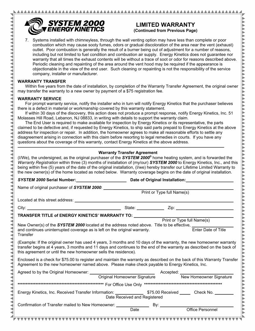
Oil Heat – Eighteenth Edition – June 2015 34
LIMITED WARRANTY (Continued from Previous Page)
7. Systems installed with chimneyless, through the wall venting option may have less than complete or poor
combustion which may cause sooty fumes, odors or gradual discoloration of the area near the vent (exhaust) outlet. Poor combustion is generally the result of a burner being out of adjustment for a number of reasons, including but not limited to fuel condition and combustion air supply. Energy Kinetics does not guarantee nor warranty that all times the exhaust contents will be without a trace of soot or odor for reasons described above. Periodic cleaning and repainting of the area around the vent hood may be required if the appearance is objectionable in the view of the end user. Such cleaning or repainting is not the responsibility of the service company, installer or manufacturer.
WARRANTY TRANSFER Within five years from the date of installation, by completion of the Warranty Transfer Agreement, the original owner
may transfer the warranty to a new owner by payment of a $75 registration fee.
WARRANTY SERVICE For prompt warranty service, notify the installer who in turn will notify Energy Kinetics that the purchaser believes
there is a defect in material or workmanship covered by this warranty statement. If within 30 days of the discovery, this action does not produce a prompt response, notify Energy Kinetics, Inc. 51
Molasses Hill Road, Lebanon, NJ 08833, in writing with details to support the warranty claim. The End User is required to make available for inspection by Energy Kinetics or its representative, the parts
claimed to be defective and, if requested by Energy Kinetics, to ship said parts prepaid to Energy Kinetics at the above address for inspection or repair. In addition, the homeowner agrees to make all reasonable efforts to settle any disagreement arising in connection with this claim before resorting to legal remedies in courts. If you have any questions about the coverage of this warranty, contact Energy Kinetics at the above address.
Warranty Transfer Agreement (I/We), the undersigned, as the original purchaser of the SYSTEM 2000 home heating system, and is forwarded the Warranty Registration within three (3) months of installation of (my/our) SYSTEM 2000 to Energy Kinetics, Inc., and this being within five (5) years of the date of the original installation, (I/we) hereby transfer our Lifetime Limited Warranty to the new owner(s) of the home located as noted below. Warranty coverage begins on the date of original installation.
SYSTEM 2000 Serial Number: Date of Original Installation:
Name of original purchaser of SYSTEM 2000: Print or Type full Name(s)
Located at this street address:
City: State: Zip:
TRANSFER TITLE of ENERGY KINETICS’ WARRANTY TO: Print or Type full Name(s) New Owner(s) of the SYSTEM 2000 located at the address noted above. Title to be effective, and continues uninterrupted coverage as is left on the original warranty. Enter Date of Title Transfer
(Example: If the original owner has used 4 years, 3 months and 10 days of the warranty, the new homeowner warranty transfer begins at 4 years, 3 months and 11 days and continues to the end of the warranty as described on the back of this agreement or until the new homeowner sells the residence).
Enclosed is a check for $75.00 to register and maintain the warranty as described on the back of this Warranty Transfer Agreement to the new homeowner named above. Please make check payable to Energy Kinetics, Inc.
Agreed to by the Original Homeowner: Accepted: Original Homeowner Signature New Homeowner Signature
***************************************************** For Office Use Only ************************************************
Energy Kinetics, Inc. Received Transfer Information: $75.00 Received Check No. Date Received and Registered
Confirmation of Transfer mailed to New Homeowner: By: Date Office Personnel


![Debian Installer Basics - start [Unix-AG-Wiki] · PDF fileDebian Installer Debian Installer I Installationsmedium für Debian I verschiedene Typen: I CD- und DVD-Installer: für Installation](https://img.pdfslide.us/doc/110x75/5a79b7b97f8b9ad7608bc8f9/debian-installer-basics-start-unix-ag-wiki-installer-debian-installer-i-installationsmedium.jpg)