Embed Size (px)
Citation preview

HR3000 SERIES C2FRONT UNIVERSAL HY-RAIL®
GUIDE WHEEL UNIT
HYDRAULICALLY OPERATED
OPERATOR'S SERVICE
AND PARTS MANUAL
ISSUED 10 - 2006 BULLETIN 1526
© 2006 HARSCO TRACK TECHNOLOGIES, HARSCO CORPORATION

�THIS MANUAL CONTAINS VITAL INFORMATION FOR THE SAFE USE AND
EFFICIENT OPERATION OF THE VEHICLE EQUIPPED WITH HY-RAIL®
GUIDE WHEEL EQUIPMENT. CAREFULLY READ THIS OPERATOR'S
MANUAL BEFORE USING THE VEHICLE. FAILURE TO ADHERE TO THE
INSTRUCTIONS COULD RESULT IN BODILY INJURY AND/OR PROPERTY
DAMAGE.
HY-RAIL® is a registered trademark of Harsco Track Technologies, Harsco Corporation.
When this manual is received, record the guide wheel unit serial numbers in the spaces provided in
the General Information and Parts Sections for future reference, in case the serial number tags
ever become unreadable. A Manual must remain with the vehicle. Additional or replacement
manuals may be obtained by calling or writing Harsco Track Technologies, Harsco Corporation.
All information, illustrations and specifications in this manual are based on the latest information
available at the time of publication. Harsco Track Technologies, Harsco Corporation reserves the
right to make changes at any time without notice.
FACILITY LOCATIONS
Harsco Track Technologies
415 North Main Street
Fairmont, MN
56031-1837
Tel: (507) 235-3361
Fax: (507) 235-7370
Harsco Track Technologies
200 South Jackson Road
Ludington, MI
49431
Tel: (231) 843-3431
Fax: (231) 843-4830
Harsco Track Technologies
2401 Edmund Road, Box 20
Cayce-West Columbia, SC
29171-0020
Tel: (803) 822-9160
Fax: (803) 822-7471
Harsco Track Technologies
Giltway, Giltbrook
Nottingham, NG16 2GQ
England
Tel: 0115 938 7000
Fax: 0115 938 7001
Harsco Track Technologies
4 Strathwyn Street, PO Box 5287
Brendale, Queensland 4500
Australia
Tel: 61 7 205 6500
Fax: 61 7 205 7369
Printed in U.S.A.
CAUTION

TABLE OF CONTENTS
GENERAL INFORMATION SECTION
OPERATION SECTION
ADJUSTMENTS SECTION
MAINTENANCE SECTION
TROUBLESHOOTING SECTION
PARTS SECTION
VEHICLE APPLICATIONS SECTION
CONVERSION TABLES APPENDIX
SAE J1273 APPENDIX
1
2
3
4
5
6
7
A
B

NOTES

SECTION 1 - GENERAL INFORMATION
TABLE OF CONTENTS
1.1 Safety Information . . . . . . . . . . . . . . . . . . . . . . . . . . . . . . . . . . . . . . . . . . . . . . . . . 1 - 2
1.1.1 Hazard Seriousness . . . . . . . . . . . . . . . . . . . . . . . . . . . . . . . . . . . . . . . . . . . . . 1 - 2
1.2 Description . . . . . . . . . . . . . . . . . . . . . . . . . . . . . . . . . . . . . . . . . . . . . . . . . . . . . . . 1 - 5
1.3 Vehicle Orientation. . . . . . . . . . . . . . . . . . . . . . . . . . . . . . . . . . . . . . . . . . . . . . . . . 1 - 5
1.4 Serial Numbers . . . . . . . . . . . . . . . . . . . . . . . . . . . . . . . . . . . . . . . . . . . . . . . . . . . 1 - 6
1.5 Specifications . . . . . . . . . . . . . . . . . . . . . . . . . . . . . . . . . . . . . . . . . . . . . . . . . . . . . 1 - 6
1.5.1 Vehicle . . . . . . . . . . . . . . . . . . . . . . . . . . . . . . . . . . . . . . . . . . . . . . . . . . . . . . . 1 - 6
1.5.2 Guide Wheel Unit . . . . . . . . . . . . . . . . . . . . . . . . . . . . . . . . . . . . . . . . . . . . . . . 1 - 6
1
HR3000C2 GENERAL INFORMATION PAGE 1 - 1
BULLETIN 1526 ISSUED 10 - 2006

1.1 Safety Information
SAFETY IS A CRITICAL FACTOR IN THE DESIGN OF HARSCO TRACK TECHNOLOGIES
EQUIPMENT. THE BEST SAFETY PROGRAM STARTS WITH A SAFETY CONSCIOUS
OPERATOR. THE SAFETY INFORMATION HIGHLIGHTED IN THIS BULLETIN DESCRIBES
SAFE OPERATING PRACTICES FOR THE BENEFIT OF THE WORKERS WHO WILL USE
OUR EQUIPMENT IN THEIR DAILY JOBS.
1.1.1 Hazard Seriousness
Signal Words: DANGER, WARNING and CAUTION are used to identify levels of hazard
seriousness.
DANGER - Immediate hazards which WILL result in sever bodily injury or death.
WARNING - Hazards or unsafe practices which COULD result in severe bodily injury
or death.
CAUTION - Hazards or unsafe practices which COULD result in minor bodily injury
and / or product or property damage.
1
PAGE 1 - 2 GENERAL INFORMATION HR3000C2
ISSUED 10 - 2006 BULLETIN 1526
THIS SYMBOL MEANS: ATTENTION! BECOME ALERT!
YOUR SAFETY IS INVOLVED.
DANGER
WARNING
CAUTION

1.1 Safety Information
� APPLY THE VEHICLE PARKING BRAKE AND STOP THE ENGINE WHEN
PERFORMING MAINTENANCE, MAKING ADJUSTMENTS, WORKING
UNDER VEHICLE OR GUIDE WHEEL EQUIPMENT OR WHENEVER
UNINTENDED MOVEMENT OF THE VEHICLE COULD OCCUR, UNLESS
OTHERWISE INSTRUCTED IN THIS MANUAL.
� MAKE SURE ALL PERSONS ARE CLEAR OF VEHICLE BEFORE
PERFORMING ANY OPERATING FUNCTIONS.
� KEEP ALL PARTS OF THE BODY AND LOOSE CLOTHING CLEAR OF ALL
MOVING PARTS OF THE VEHICLE OR GUIDE WHEEL EQUIPMENT.
� UNDERSTAND EQUIPMENT OPERATION AND BE AWARE OF ALL PINCH
POINTS BEFORE OPERATING OR MAKING ADJUSTMENTS TO GUIDE
WHEEL EQUIPMENT.
� IF A DERAILMENT SHOULD OCCUR WHILE VEHICLE IS OPERATING IN
ELECTRIFIED 3RD-RAIL TERRITORY, VEHICLE OR GUIDE WHEEL
EQUIPMENT MIGHT BE IN ELECTRICAL CONTACT WITH ELECTRIFIED
RAIL. DO NOT ATTEMPT TO EXIT FROM VEHICLE UNTIL ELECTRICAL
POWER TO 3RD-RAIL HAS BEEN TURNED OFF.
� DO NOT EXCEED 25 MPH (40 km/h) WHEN OPERATING VEHICLE ON
TRACK. RAILROAD RULES GOVERNING SPEEDS SHOULD BE OBSERVED
AT ALL TIMES. REDUCE SPEED WHEN PROPELLING VEHICLE THROUGH
SWITCHES, CROSSINGS, BRANCH LINES AND ANY SPECIAL TRACK
WORKS. OPERATING VEHICLE AT UNSAFE SPEEDS COULD RESULT IN
DERAILMENT OF VEHICLE.
� CHECK AND CORRECT GUIDE WHEEL EQUIPMENT ALIGNMENT
PROMPTLY IF MISALIGNMENT IS INDICATED.
1
HR3000C2 GENERAL INFORMATION PAGE 1 - 3
BULLETIN 1526 ISSUED 10 - 2006
WARNING

1.1 Safety Information
� AT MAXIMUM LOADED GROSS VEHICLE WEIGHT ON TRACK (including
driver, passengers, equipment, tools, payload, etc.) DO NOT EXCEED ANY
OF THE FOLLOWING:
� VEHICLE'S G.V.W.R. (Gross Vehicle Weight Rating).
� VEHICLE'S FRONT G.A.W.R. (Gross Axle Weight Rating) OR THE FRONT
GUIDE WHEEL UNIT RATED LOAD CAPACITY, WHICHEVER IS LOWER.
� VEHICLE'S REAR G.A.W.R. (Gross Axle Weight Rating) OR THE SUM OF
THE REAR GUIDE WHEEL UNIT RATED LOAD CAPACITY PLUS (+)
VEHICLE'S REAR TIRE/WHEEL RATED LOAD CAPACITY, WHICHEVER IS
LOWER.
� COMPONENTS RATED LOAD CAPACITY:
A. TIRE MANUFACTURER'S RATED LOAD CAPACITY
B. VEHICLE'S WHEEL RATED LOAD CAPACITY
C. FRONT GUIDE WHEEL UNIT RATED LOAD CAPACITY:
13,000 lbs (5,897 kg)
6,500 lbs (2,948 kg) maximum per guide wheel
FAILURE TO HEED THESE WARNINGS COULD RESULT IN SEVERE BODILY
INJURY.
� OBSERVE AND FOLLOW ALL RAILROAD SAFETY RULES AND
REGULATIONS.
� KNOW THE POSITIONS AND FUNCTIONS OF ALL CONTROLS BEFORE
ATTEMPTING TO OPERATE VEHICLE.
� THIS GUIDE WHEEL EQUIPMENT IS DESIGNED WITH YOUR SAFETY IN
MIND. NEVER DISCONNECT AND/OR ATTEMPT TO OVERRIDE SAFETY
FEATURES.
FAILURE TO HEED THESE PRECAUTIONS COULD RESULT IN BODILY
INJURY AND/OR PROPERTY DAMAGE.
Note: To help ensure safe operation of this equipment, keep all safety decals clean andlegible. Replace safety decals when necessary with new decals, listed in the PartsSection of this manual.
1
PAGE 1 - 4 GENERAL INFORMATION HR3000C2
ISSUED 10 - 2006 BULLETIN 1526
WARNING
CAUTION

1.2 Description
The HR3000 Series C2 HY-RAIL® guide wheel equipment can be applied to the front of various
cab chassis trucks with single or tandem rear axles and dual wheels. The vehicle's G.V.W.R.
(gross vehicle weight rating) and/or G.A.W.R. (gross axle weight rating) must comply with
specifications recommended by Harsco Track Technologies. For information regarding special
applications, contact Harsco Track Technologies, Harsco Corporation, Fairmont, Minnesota.
The guide wheel unit is raised and lowered hydraulically. Hydraulic power may be supplied from
the vehicle system or from an optional power pack. The guide wheel unit is mounted onto the
vehicle frame. When the guide wheels are in the "highway" position, the weight of the guide wheel
unit is carried on the vehicle frame, above the springs. Load bearing guide wheels assemblies
guide the vehicle during on track operation. The guide wheel unit is designed to extend under the
vehicle's front suspension, when in the "rail" position and lift the front of the vehicle, raising the
front tires above the rails to ensure that the tires do not come into contact with the rails while the
vehicle is propelling through crossings, switches, etc. The guide wheel unit utilizes the vehicle's
suspension to support the vehicle front load when on track. A steering lock is used during on track
operation. The steering lock holds the vehicle's steering wheel in place to ensure the vehicle's
front tires remain straight.
The vehicle's rear inner dual wheels are used for propulsion on the track. On track braking is
provided by the vehicle's rear brakes, the front guide wheel unit's brakes and the rear guide wheel
unit's brakes, if so equipped. Since the guide wheel unit brakes are air actuated, the vehicle on
which the guide wheel equipment is mounted should be equipped with air brakes. If not, an electric
/ air system is available to provide air for the guide wheel unit brakes.
1.3 Vehicle Orientation
Front - rear and left - right are determined from the vehicle operator's seat.
1
HR3000C2 GENERAL INFORMATION PAGE 1 - 5
BULLETIN 1526 ISSUED 10 - 2006

1.4 Serial Numbers
When this bulletin is received, complete the following record from the serial number tag on the
guide wheel unit. Always provide these factory serial numbers when calling or writing about the
unit. The serial number tag is located on the frame assembly of the unit.
1.5 Specifications
1.5.1 Vehicle
The vehicle's G.V.W.R. (gross vehicle weight rating) and/or G.A.W.R. (gross axle weight rating)
must comply with specifications recommended by Harsco Track Technologies. For information
regarding special applications, contact Harsco Track Technologies, Harsco Corporation,
Fairmont, Minnesota.
1.5.2 Guide Wheel Unit
Track Gauge . . . . . . . . . . . . . . . . . . . . . . . . . . . . . . . . . . . . . . . . . 56-1/2 in (1435 mm)
Guide Wheels - Flange Diameter . . . . . . . . . . . . . . . . . . . . . . . . . 14-3/4 in (375 mm)
- Tread Diameter. . . . . . . . . . . . . . . . . . . . . . . . . . . 12-1/2 in (318 mm)
Weight . . . . . . . . . . . . . . . . . . . . . . . . . . . . . . . . . . . . . . . . . . . . . . . 890 lbs (404 kg)
Maximum Load Capacity. . . . . . . . . . . . . . . . . . . . . . . . . . . . . . . 13,000 lbs (5,896 kg)
Maximum Load Per Guide Wheel . . . . . . . . . . . . . . . . . . . . . . . . . 6,500 lbs (2,948 kg)
1
PAGE 1 - 6 GENERAL INFORMATION HR3000C2
ISSUED 10 - 2006 BULLETIN 1526
FIGURE 1-1
GUIDE WHEEL UNIT SERIAL NUMBER TAG
SECTION 2 - OPERATION
TABLE OF CONTENTS
2.1 Preparing Vehicle For Operation . . . . . . . . . . . . . . . . . . . . . . . . . . . . . . . . . . . . . . 2 - 3
2.2 Preparing Guide Wheel Equipment For Operation. . . . . . . . . . . . . . . . . . . . . . . . . 2 - 4
2.3 Misalignment Indicators . . . . . . . . . . . . . . . . . . . . . . . . . . . . . . . . . . . . . . . . . . . . . 2 - 4
2.4 Placing Vehicle On Track . . . . . . . . . . . . . . . . . . . . . . . . . . . . . . . . . . . . . . . . . . . . 2 - 5
2.4.1 Lower Front Guide Wheels . . . . . . . . . . . . . . . . . . . . . . . . . . . . . . . . . . . . . . . . 2 - 6
2.4.2 Steering Locks . . . . . . . . . . . . . . . . . . . . . . . . . . . . . . . . . . . . . . . . . . . . . . . . . 2 - 8
2.4.3 Rail Brakes . . . . . . . . . . . . . . . . . . . . . . . . . . . . . . . . . . . . . . . . . . . . . . . . . . . . 2 - 9
2.4.4 Checking Vehicle Tire Clearance Above Rails . . . . . . . . . . . . . . . . . . . . . . . . . 2 - 9
2.5 Guide Wheel Load On Track . . . . . . . . . . . . . . . . . . . . . . . . . . . . . . . . . . . . . . . . . 2 - 10
2.5.1 Checking Front Guide Wheel Load On Track . . . . . . . . . . . . . . . . . . . . . . . . . . 2 - 10
2.6 Propelling On Track . . . . . . . . . . . . . . . . . . . . . . . . . . . . . . . . . . . . . . . . . . . . . . . . 2 - 11
2.7 Braking On Track . . . . . . . . . . . . . . . . . . . . . . . . . . . . . . . . . . . . . . . . . . . . . . . . . . 2 - 12
2.7.1 Vehicles with Anti-Lock Brake Systems (ABS) . . . . . . . . . . . . . . . . . . . . . . . . . 2 - 12
2.8 Vehicles Equipped With Crane Or Aerial Lift Device . . . . . . . . . . . . . . . . . . . . . . . 2 - 13
2.9 Removing Vehicle From Track . . . . . . . . . . . . . . . . . . . . . . . . . . . . . . . . . . . . . . . . 2 - 15
2.9.1 Raise Front Guide Wheels . . . . . . . . . . . . . . . . . . . . . . . . . . . . . . . . . . . . . . . . 2 - 16
2.9.2 Steering Locks . . . . . . . . . . . . . . . . . . . . . . . . . . . . . . . . . . . . . . . . . . . . . . . . . 2 - 18
2.10 Highway Operation. . . . . . . . . . . . . . . . . . . . . . . . . . . . . . . . . . . . . . . . . . . . . . . . . 2 - 19
2.11 Towing Trailer / Equipment With Vehicle On Track . . . . . . . . . . . . . . . . . . . . . . . . 2 - 20
2.12 Towing Trailer / Equipment With Vehicle On Road . . . . . . . . . . . . . . . . . . . . . . . . 2 - 23
2.13 Towing Disabled Vehicle On Track . . . . . . . . . . . . . . . . . . . . . . . . . . . . . . . . . . . . 2 - 26
2.14 Towing Disabled Vehicle On Road. . . . . . . . . . . . . . . . . . . . . . . . . . . . . . . . . . . . . 2 - 29
2
HR3000C2 FRONT OPERATION PAGE 2 - 1
BULLETIN 1526 ISSUED 10 - 2006

NOTES
2
PAGE 2 - 2 OPERATION HR3000C2 FRONT
ISSUED 10 - 2006 BULLETIN 1526

2.1 Preparing Vehicle for Operation
Be sure the vehicle is in operating condition by checking the following:
a. Engine oil level.
b. Radiator fluid level.
c. Fuel tank level.
d. Hydraulic reservoir oil level.
e. Brakes work properly.
f. Parking brake works properly.
g. Head, brake and signal lights work properly.
h. Tires properly inflated to the manufacturer's recommended maximum pressure printed
on the sidewall of the tires, or the wheel manufacturer's recommended maximum
pressure stamped on the wheel, whichever is lower.
I. Vehicle wheels: Lug nuts / bolts tightened to the proper torque, inspect vehicle wheels,
lug bolts and lug nuts for wear or damage. For vehicle wheel, lug bolt and lug nut
inspection information refer to the USER'S GUIDE TO WHEELS AND RIMS produced
by THE MAINTENANCE COUNCIL. To obtain this guide, contact:
THE MAINTENANCE COUNCIL
AMERICAN TRUCKING ASSOCIATION
2200 MILL ROAD
ALEXANDRIA, VA. 22314
Phone: (703) 838-1763
j. Any other normal maintenance requirements.
2
HR3000C2 FRONT OPERATION PAGE 2 - 3
BULLETIN 1526 ISSUED 10 - 2006

2.2 Preparing Guide Wheel Equipment For Operation
Be sure the guide wheel equipment is in operating condition by checking the following:
a. Air and hydraulic hoses and fittings for damage, wear or leaks.
b. Overall for damaged or worn parts.
c. Properly lubricated at the recommended operating mileage intervals.
d. Brakes work properly.
e. Hydraulic pressure properly adjusted.
2.3 Misalignment Indicators
� BEFORE OPERATING A VEHICLE WITH NEWLY INSTALLED GUIDE WHEEL
EQUIPMENT ON TRACK, VERIFY THAT THE GUIDE WHEEL EQUIPMENT
ALIGNMENT PROCEDURE HAS BEEN COMPLETED. CHECK AND
CORRECT ALIGNMENT PROMPTLY IF MISALIGNMENT IS INDICATED.
MISALIGNMENT OF GUIDE WHEEL EQUIPMENT COULD RESULT IN
DERAILMENT OF VEHICLE AND SEVERE BODILY INJURY.
The following conditions may indicate that minor adjustments to the guide wheel equipment
alignment are necessary. If any of these conditions occur during operation, perform the Track
Test, see Adjustment Section - Vehicle Track Test and/or complete the Alignment Procedure, see
Adjustment - Guide Wheel Equipment Alignment Procedure.
1. Excessive flange or tread wear on any of the rail guide wheels.
2. Vehicle pulls noticeably to the left or the right during on track operation.
3. Vibration felt throughout the vehicle at various speeds during on track operation.
2
PAGE 2 - 4 OPERATION HR3000C2 FRONT
ISSUED 10 - 2006 BULLETIN 1526
WARNING
2.4 Placing Vehicle On Track
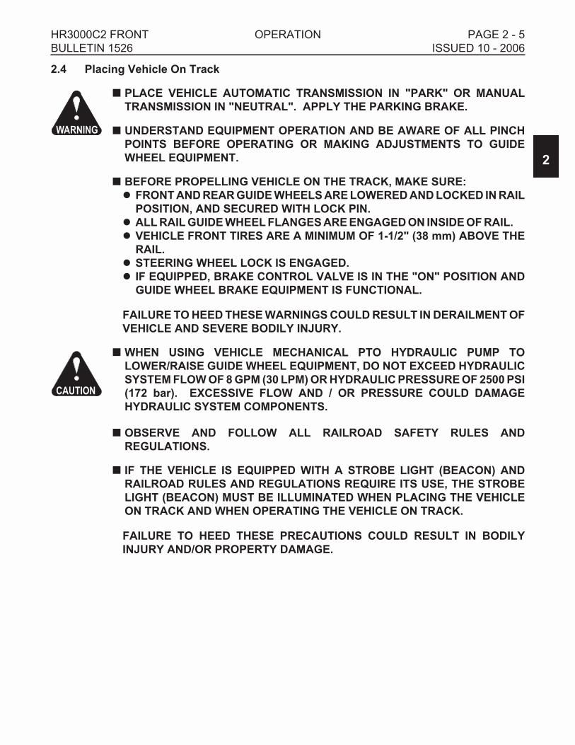
� PLACE VEHICLE AUTOMATIC TRANSMISSION IN "PARK" OR MANUAL
TRANSMISSION IN "NEUTRAL". APPLY THE PARKING BRAKE.
� UNDERSTAND EQUIPMENT OPERATION AND BE AWARE OF ALL PINCH
POINTS BEFORE OPERATING OR MAKING ADJUSTMENTS TO GUIDE
WHEEL EQUIPMENT.
� BEFORE PROPELLING VEHICLE ON THE TRACK, MAKE SURE:
� FRONT AND REAR GUIDE WHEELS ARE LOWERED AND LOCKED IN RAIL
POSITION, AND SECURED WITH LOCK PIN.
� ALL RAIL GUIDE WHEEL FLANGES ARE ENGAGED ON INSIDE OF RAIL.
� VEHICLE FRONT TIRES ARE A MINIMUM OF 1-1/2" (38 mm) ABOVE THE
RAIL.
� STEERING WHEEL LOCK IS ENGAGED.
� IF EQUIPPED, BRAKE CONTROL VALVE IS IN THE "ON" POSITION AND
GUIDE WHEEL BRAKE EQUIPMENT IS FUNCTIONAL.
FAILURE TO HEED THESE WARNINGS COULD RESULT IN DERAILMENT OF
VEHICLE AND SEVERE BODILY INJURY.
�WHEN USING VEHICLE MECHANICAL PTO HYDRAULIC PUMP TO
LOWER/RAISE GUIDE WHEEL EQUIPMENT, DO NOT EXCEED HYDRAULIC
SYSTEM FLOW OF 8 GPM (30 LPM) OR HYDRAULIC PRESSURE OF 2500 PSI
(172 bar). EXCESSIVE FLOW AND / OR PRESSURE COULD DAMAGE
HYDRAULIC SYSTEM COMPONENTS.
� OBSERVE AND FOLLOW ALL RAILROAD SAFETY RULES AND
REGULATIONS.
� IF THE VEHICLE IS EQUIPPED WITH A STROBE LIGHT (BEACON) AND
RAILROAD RULES AND REGULATIONS REQUIRE ITS USE, THE STROBE
LIGHT (BEACON) MUST BE ILLUMINATED WHEN PLACING THE VEHICLE
ON TRACK AND WHEN OPERATING THE VEHICLE ON TRACK.
FAILURE TO HEED THESE PRECAUTIONS COULD RESULT IN BODILY
INJURY AND/OR PROPERTY DAMAGE.
2
HR3000C2 FRONT OPERATION PAGE 2 - 5
BULLETIN 1526 ISSUED 10 - 2006
WARNING
CAUTION

2.4 Placing Vehicle On Track
1. Ensure that highway vehicles are not approaching the grade crossing while placing the
vehicle on track. Flag the crossing per railroad rules and regulations to ensure safety.
2. At a road crossing, drive the vehicle about 25 feet (7.6 m) past the track. Back the vehicle
onto the rails so that the rear vehicle wheels are centered on the rails. On vehicles with
dual rear wheels, the inner dual wheels must be centered on the rails. It may be
necessary to move the vehicle back and forth several times to get the wheels centered on
the rail properly.
3. Place the vehicle automatic transmission in "PARK" or manual transmission in
"NEUTRAL". Apply the parking brake.
4. Engage the mechanical PTO hydraulic pump or start the auxiliary hydraulic power source.
If the vehicle is equipped with an auxiliary control valve, place the valve in the proper
position to direct hydraulic oil flow to the guide wheel equipment.
5. Lower and lock the rear guide wheels first. The rear guide wheels should be lowered first
so the front tires of the vehicle can be maneuvered to align the front guide wheels with the
rails. See the Operator's Service And Parts Manual provided with the rear guide wheel
unit for the procedure to lower the rear guide wheels.
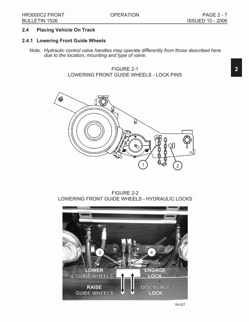
2.4.1 Lowering Front Guide Wheels - See Figures 2-1 and 2-2
1. The front guide wheel unit may be equipped with manual lock pins or hydraulically
actuated lock pins that secure the unit in the "highway" position.
2. Manual Lock Pins: Move Control Valve Handle (3) slightly to raise or lower the guide
wheels to release any tension on the lock pins. Rotate lock pin (1) so the flat on the
washer is in line with the securing angle. Pull the lock pin out and place it in its "rail"
position storage hole (2). Make sure the pin is rotated so the washer is engaged behind
the securing angle.
3. Hydraulic Locks: Move Control Valve Handle (3) slightly to raise or lower the guide wheels
to release any tension on the lock pins. Push Control Valve Handle (4) down to disengage
the locks. Visually check to make sure the locks are disengaged.
4. Pull control valve handle (3) up to lower the guide wheels. Make sure the guide wheels
are fully lowered and the rail guide wheel flanges are engaged on the inside of the rails.
Release the Control Valve Handle.
5. Make sure the vehicle front wheels are raised and suspended at least 1-1/2 inch (38 mm)
above the top of the rails.
6. Disengage the mechanical PTO hydraulic pump or stop the auxiliary hydraulic power
source. If the vehicle is equipped with an auxiliary control valve, place the valve in the
proper position to shut off hydraulic oil flow to the guide wheel equipment.
2
PAGE 2 - 6 OPERATION HR3000C2 FRONT
ISSUED 10 - 2006 BULLETIN 1526
2.4 Placing Vehicle On Track
2.4.1 Lowering Front Guide Wheels
Note: Hydraulic control valve handles may operate differently from those described heredue to the location, mounting and type of valve.
2
HR3000C2 FRONT OPERATION PAGE 2 - 7
BULLETIN 1526 ISSUED 10 - 2006
FIGURE 2-2
LOWERING FRONT GUIDE WHEELS - HYDRAULIC LOCKS
04-227
43
ENGAGE
LOCK
DISENGAGEDISENGAGE
LOCK
LOWER
GUIDE WHEELSGUIDE WHEELS
RAISE
GUIDE WHEELSGUIDE WHEELS
FIGURE 2-1
LOWERING FRONT GUIDE WHEELS - LOCK PINS
1 2
2.4 Placing Vehicle On Track
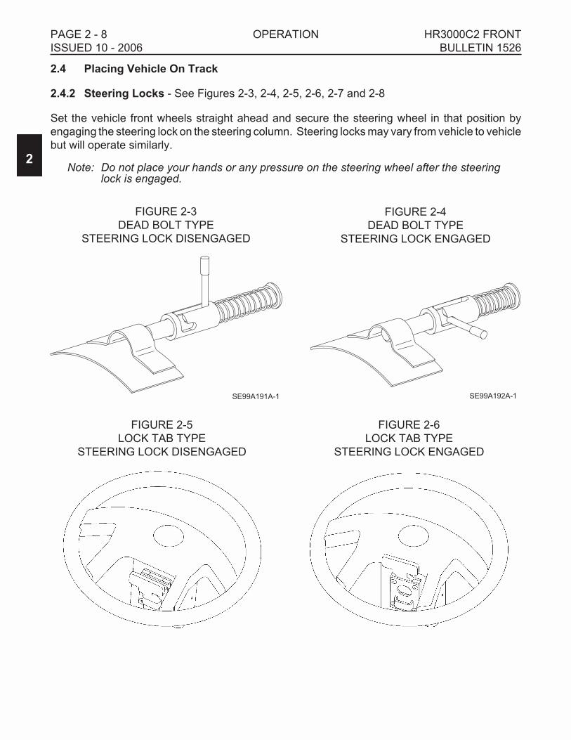
2.4.2 Steering Locks - See Figures 2-3, 2-4, 2-5, 2-6, 2-7 and 2-8
Set the vehicle front wheels straight ahead and secure the steering wheel in that position by
engaging the steering lock on the steering column. Steering locks may vary from vehicle to vehicle
but will operate similarly.
Note: Do not place your hands or any pressure on the steering wheel after the steeringlock is engaged.
2
PAGE 2 - 8 OPERATION HR3000C2 FRONT
ISSUED 10 - 2006 BULLETIN 1526
FIGURE 2-4
DEAD BOLT TYPE
STEERING LOCK ENGAGED
SE99A192A-1
FIGURE 2-3
DEAD BOLT TYPE
STEERING LOCK DISENGAGED
SE99A191A-1
FIGURE 2-5
LOCK TAB TYPE
STEERING LOCK DISENGAGED
FIGURE 2-6
LOCK TAB TYPE
STEERING LOCK ENGAGED

2.4 Placing Vehicle On Track
2.4.2 Steering Locks
2.4.3 Rail Brakes
If so equipped, move the Rail Wheel Brake Control Valve to the ON position to activate the guide
wheel equipment brakes whenever the vehicle is on track. The vehicle brake pedal will actuate the
vehicle brakes and the guide wheel equipment brakes simultaneously.
2.4.4 Check Vehicle Front Tire Clearance Above Rail
If the vehicle's front tire clearance above the rail is less than 1-1/2" (38 mm) the vehicle may be
overloaded or the unit was not properly set-up when it was applied to the vehicle. Never operate
the vehicle on track when the front tire clearance above the rail is less than 1-1/2" (38 mm).
2
HR3000C2 FRONT OPERATION PAGE 2 - 9
BULLETIN 1526 ISSUED 10 - 2006
FIGURE 2-7
VELCRO STEERING LOCK OFF
FIGURE 2-8
VELCRO STEERING LOCK ON

2.5 Guide Wheel Load On Track
� IMPROPER LOADING OF GUIDE WHEEL EQUIPMENT CAN CAUSE
DERAILMENT OF VEHICLE.
� ALWAYS CHECK THE GUIDE WHEEL LOAD BEFORE OPERATING THE
VEHICLE ON TRACK.
� NEVER OPERATE THE VEHICLE ON TRACK IF LOAD EXCEEDS THE
MAXIMUM RATED LOAD OF THE FRONT AND/OR REAR GUIDE WHEEL
UNITS. THE MAXIMUM LOAD ON THE FRONT GUIDE WHEEL UNIT IS 13,000
LBS (5896 kg) OR 6,500 LBS (2948 kg) MAXIMUM PER GUIDE WHEEL.
� NEVER OPERATE THE VEHICLE ON TRACK IF CLEARANCE BETWEEN
VEHICLE FRONT TIRES AND RAIL IS LESS THAN 1-1/2" (38 mm).
FAILURE TO HEED THESE WARNINGS COULD RESULT IN DERAILMENT OF
VEHICLE AND/OR SEVERE BODILY INJURY.
Whenever the vehicle is loaded or additional load is added to the existing vehicle load on track,
check the load on the front guide wheels. The maximum load on the front guide wheel unit is
13,000 lbs (5896 kg) or 6,500 lbs (2948 kg) maximum per guide wheel. Also, check the load on the
rear guide wheel unit. See the Operator's Service And Parts Manual provided with the rear guide
wheel unit for information on checking the load on the rear guide wheel unit.
2.5.1 Checking Front Guide Wheel Load
1. To check the load on the front guide wheels, the guide wheels must be located on a scale.
Check the load on the guide wheel unit and on both guide wheels individually.
2. Apply the parking brake. Stop the engine.
3. The maximum load on the front guide wheel unit is 13,000 lbs (5896 kg) or 6,500 lbs (2948
kg) maximum per guide wheel. The guide wheel load must also be equal or within ± 100
lbs (45 kg) on the both the left and right ends of the guide wheel unit.
If the front guide wheel load does not exceed the maximum load capacity, the load on the
front guide wheel is acceptable.
If the front guide wheel load does exceed the maximum load capacity, the load must be
redistributed or some of the load removed. Never operate the vehicle on track if the load
on the front guide wheel exceeds the maximum load capacity of 13,000 lbs (5896 kg) or
6,500 lbs (2948 kg) maximum per guide wheel.
4. Rear Guide Wheel Load: Whenever the vehicle is loaded, additional load is added to the
existing vehicle load or the load on the vehicle is re-distributed, check the load on the rear
guide wheels. See the Operator's Service And Parts Manual provided with the rear guide
wheel unit for the procedure for checking the load on the rear guide wheel unit.
2
PAGE 2 - 10 OPERATION HR3000C2 FRONT
ISSUED 10 - 2006 BULLETIN 1526
WARNING

2.6 Propelling On Track
� IMPROPER LOADING OF HY-RAIL® EQUIPPED VEHICLE CAN CAUSE
DERAILMENT OF VEHICLE.
� ALWAYS CHECK GUIDE WHEEL LOAD BEFORE OPERATING THE VEHICLE
ON TRACK.
� NEVER OPERATE VEHICLE ON TRACK IF LOAD EXCEEDS MAXIMUM
RATED LOAD OF FRONT AND/OR REAR GUIDE WHEEL UNITS.
� NEVER OPERATE VEHICLE ON TRACK IF CLEARANCE BETWEEN VEHICLE
FRONT TIRE AND RAIL IS LESS THAN 1-1/2" (38 mm).
FAILURE TO HEED THESE WARNINGS COULD RESULT IN DERAILMENT OF
VEHICLE AND/OR SEVERE BODILY INJURY.
� BEFORE OR WHEN PROPELLING ON TRACK:
� OBSERVE AND FOLLOW ALL RAILROAD SAFETY RULES AND
REGULATIONS.
� OPERATOR MUST LOOK IN ALL DIRECTIONS FOR PERSONS OR
OBJECTS ON OR ADJACENT TO THE TRACK.
� DO NOT ACCELERATE SUDDENLY. TRACTION IS REDUCED ON TRACK,
SPINNING VEHICLE TIRES COULD DAMAGE THEM.
� DO NOT EXCEED 25 MPH (40 km/h) WHEN OPERATING VEHICLE ON
TRACK. RAILROAD RULES GOVERNING SPEEDS SHOULD BE
OBSERVED AT ALL TIMES. REDUCE SPEED WHEN PROPELLING
VEHICLE THROUGH SWITCHES, ROAD CROSSINGS, BRANCH LINES
AND ANY SPECIAL TRACK WORKS. OPERATING VEHICLE AT UNSAFE
SPEEDS COULD RESULT IN DERAILMENT OF THE VEHICLE.
� STEERING LOCK MUST BE ENGAGED AT ALL TIMES WHEN OPERATING
VEHICLE ON TRACK.
� IF THE VEHICLE IS EQUIPPED WITH A STROBE LIGHT (BEACON) AND
RAILROAD RULES AND REGULATIONS REQUIRE ITS USE, THE STROBE
LIGHT (BEACON) MUST BE ILLUMINATED WHEN OPERATING THE
VEHICLE ON TRACK.
FAILURE TO HEED THESE PRECAUTIONS COULD RESULT IN BODILY
INJURY AND/OR PROPERTY DAMAGE.
Vehicles equipped with the HR3000 Series C2 HY-RAIL® Guide Wheel Equipment use the
vehicle propulsion system to propel on track. Do not accelerate suddenly. Traction is reduced on
track. Spinning the vehicle tires could damage them.
2
HR3000C2 FRONT OPERATION PAGE 2 - 11
BULLETIN 1526 ISSUED 10 - 2006
WARNING
CAUTION

2.7 Braking On Track
� PERSONS WHO OPERATE THE VEHICLE MUST BE FAMILIAR WITH TRACK
AND WEATHER CONDITIONS THAT MAY AFFECT STOPPING DISTANCE.
BE ALERT TO THESE CONDITIONS AND ALLOW ADEQUATE STOPPING
DISTANCE.
� BE PREPARED TO BRAKE AT ALL HIGHWAY CROSSINGS. THIS VEHICLE
MAY NOT OPERATE TRACK SIGNAL CIRCUITS, AND ONCOMING
VEHICLES OR PEDESTRIANS MAY NOT YIELD THE RIGHT OF WAY.
� IF EQUIPPED, RAIL WHEEL BRAKE CONTROL VALVE MUST BE IN THE
"ON" POSITION WHENEVER VEHICLE IS ON TRACK.
FAILURE TO HEED THESE PRECAUTIONS COULD RESULT IN BODILY
INJURY AND/OR PROPERTY DAMAGE.
The HR3000 Series C2 HY-RAIL® Guide Wheel Equipment may be equipped with brakes. If the
guide wheel unit is equipped with brakes, the vehicle uses a combination of the front guide wheel
unit brakes and the vehicle's rear axle brake system for braking on track. The front guide wheel
unit brakes will apply simultaneously when the vehicle brakes are applied. Stopping distance is
greater on track than on typical road surfaces. Apply the brakes gradually to avoid sliding the
vehicle tires and rail guide wheels.
2.7.1 Vehicles with Anti-Lock Brake Systems (ABS)
While operating on track, the ABS becomes ineffective in brake application at lower speeds. If the
ABS is active and the truck is moving on rail with front wheels elevated, an indicator on the dash
may come on. Since the front wheels are not rotating, the motion sensors may transmit a fault
indication to the ABS Electronic Control Unit (ECU), which signals the dash indicator to illuminate.
This will not affect rear truck braking or rail wheel braking.
When the vehicle is returned to highway operation, the ABS fault must be cleared or the ABS will
not function correctly and the indicator will remain illuminated. The fault can be cleared by
stopping and restarting the vehicle's engine. When the engine is restarted, the ABS ECU will run a
diagnostic check and the fault should be cleared. If the ABS fault does not clear, contact the brake
system manufacture for assistance.
2
PAGE 2 - 12 OPERATION HR3000C2 FRONT
ISSUED 10 - 2006 BULLETIN 1526
CAUTION

2.8 Vehicles Equipped With Crane Or Aerial Lift Device
�WHEN OPERATING CRANE, AERIAL LIFT DEVICE, ETC., WHILE THE
VEHICLE'S GUIDE WHEELS ARE ON THE RAILS, DO NOT OVERLOAD THE
GUIDE WHEEL EQUIPMENT OR EXCEED THE CAPACITY OF ANY OF THE
EQUIPMENT BEING USED.
� THE UNIT SHOULD BE EQUIPPED WITH OUTRIGGERS TO HELP PREVENT
ACCIDENTS AND THE POSSIBILITY OF DAMAGE TO THE GUIDE WHEEL
EQUIPMENT. WHEN USING THE EQUIPMENT TO TRANSFER ANY LOAD,
SET THE OUTRIGGERS ON A STABLE BASE TO PREVENT SETTLING OF
THE OUTRIGGERS AND SHIFTING OF THE VEHICLE.
� IF OPERATING CONDITIONS REQUIRE LIFTING A LOAD WITH THE CRANE
WHILE ON RAIL, BUT WITHOUT THE OUTRIGGERS BEING USED, THE
LOAD APPLIED BY LIFTING WITH THE CRANE MUST NOT OVERLOAD ANY
COMPONENT OF THE GUIDE WHEEL EQUIPMENT.
� CAREFULLY READ THE CRANE OR AERIAL LIFT DEVICE OPERATOR'S
MANUAL FOR THE SAFE USE AND EFFICIENT OPERATION OF THE
EQUIPMENT.
FAILURE TO HEED THESE WARNINGS COULD CAUSE DERAILMENT OF
THE VEHICLE RESULTING IN SEVERE BODILY INJURY AND/OR DEATH.
1. When operating a crane, aerial lift device, etc., while the vehicle's guide wheels are on the
rails, do not overload the guide wheel equipment or exceed the capacity of any of the
equipment being used.
2. The crane, aerial lift device, etc. should be equipped with outriggers to help prevent
accidents and the possibility of damage to the guide wheel equipment. When using the
crane, aerial lift device, etc. to transfer any load, set the outriggers on a stable base to
prevent settling of the outriggers and shifting of the vehicle. Carefully read the crane or
aerial lift equipment operator's manual for the safe use and efficient operation of the
equipment.
3. If operating conditions require lifting a load with the crane while on rail, but without the
outriggers being used, the load applied by lifting with the crane must not overload any
component of the guide wheel equipment.
2
HR3000C2 FRONT OPERATION PAGE 2 - 13
BULLETIN 1526 ISSUED 10 - 2006
WARNING

NOTES
2
PAGE 2 - 14 OPERATION HR3000C2 FRONT
ISSUED 10 - 2006 BULLETIN 1526

2.9 Removing Vehicle From Track
� PLACE VEHICLE AUTOMATIC TRANSMISSION IN "PARK" OR MANUAL
TRANSMISSION IN "NEUTRAL". APPLY THE PARKING BRAKE.
� UNDERSTAND EQUIPMENT OPERATION AND BE AWARE OF ALL PINCH
POINTS BEFORE OPERATING OR MAKING ADJUSTMENTS TO GUIDE
WHEEL EQUIPMENT.
� BEFORE PROPELLING VEHICLE OFF TRACK, MAKE SURE:
� FRONT AND REAR GUIDE WHEELS ARE RAISED, LOCKED IN THE
HIGHWAY POSITION, AND SECURED WITH THE LOCK PINS.
� STEERING WHEEL LOCK IS DISENGAGED.
FAILURE TO HEED THESE WARNINGS COULD RESULT IN SEVERE BODILY
INJURY.
�WHEN USING VEHICLE MECHANICAL PTO HYDRAULIC PUMP TO
LOWER/RAISE GUIDE WHEEL EQUIPMENT, DO NOT EXCEED HYDRAULIC
SYSTEM FLOW OF 8 GPM (30 LPM) OR HYDRAULIC PRESSURE OF 2500 PSI
(172 bar). EXCESSIVE FLOW AND / OR PRESSURE COULD DAMAGE
HYDRAULIC SYSTEM COMPONENTS.
� OBSERVE AND FOLLOW ALL RAILROAD SAFETY RULES AND
REGULATIONS.
� IF THE VEHICLE IS EQUIPPED WITH A STROBE LIGHT (BEACON) AND
RAILROAD RULES AND REGULATIONS REQUIRE ITS USE, THE STROBE
LIGHT (BEACON) MUST BE ILLUMINATED WHEN OPERATING AND
REMOVING THE VEHICLE FROM TRACK.
FAILURE TO HEED THESE PRECAUTIONS COULD RESULT IN BODILY
INJURY AND/OR PROPERTY DAMAGE.
2
HR3000C2 FRONT OPERATION PAGE 2 - 15
BULLETIN 1526 ISSUED 10 - 2006
WARNING
CAUTION

2.9 Removing Vehicle From Track
1. Ensure that highway vehicles are not approaching the grade crossing while placing the
vehicle on track. Flag the crossing per railroad rules and regulations to ensure safety.
2. Approach the crossing and stop with the vehicle front wheels on the crossing.
3. Place the vehicle automatic transmission in "PARK" or manual transmission in
"NEUTRAL". Apply the parking brake.
4. If so equipped, move the Rail Wheel Brake Control Valve to the OFF position, whenever
the vehicle is removed from the track for highway use.
5. Engage the mechanical PTO hydraulic pump or start the auxiliary hydraulic power source.
If the vehicle is equipped with an auxiliary control valve, place the valve in the proper
position to direct hydraulic oil flow to the guide wheel equipment.
2.9.1 Raising Front Guide Wheels - See Figures 2-9 and 2-10
1. The front guide wheel unit may be equipped with manual lock pins or hydraulically
actuated lock pins that secure the unit in the "highway" position.
2. Push control valve handle (3) down to raise the guide wheels. Make sure the guide
wheels are fully raised. Release the Control Valve Handle.
3. Manual Lock Pins: Rotate lock pin (1) so the flat on the washer is in line with the securing
angle. Pull the lock pin out of its "rail" position storage hole (2). Install the lock pin the the
"highway" position hole. Make sure the pin is rotated so the washer is engaged behind the
securing angle. If the lock pins (1) do not easily insert, move Control Valve Handle (3)
slightly to raise or lower the guide wheels to allow the lock pins to insert.
4. Hydraulic Locks: Pull Control Valve Handle (4) up to engage the locks. If the locks do not
readily engage, move Control Valve Handle (3) slightly to raise or lower the guide wheels
to allow the lock pins to engage. Visually check to make sure the locks are engaged.
5. Raise and lock the rear guide wheels in the "highway" position. See the Operator's
Service And Parts Manual provided with the rear guide wheel unit for the procedure to
raise the rear guide wheels.
6. Disengage the mechanical PTO hydraulic pump or stop the auxiliary hydraulic power
source. If the vehicle is equipped with an auxiliary control valve, place the valve in the
proper position to shut off hydraulic oil flow to the guide wheel equipment.
Note: Hydraulic control valve handles may operate differently from those described heredue to location, mounting and type of valve.
2
PAGE 2 - 16 OPERATION HR3000C2 FRONT
ISSUED 10 - 2006 BULLETIN 1526

2.9 Removing Vehicle From Track
2.9.1 Raising Front Guide Wheels
2
HR3000C2 FRONT OPERATION PAGE 2 - 17
BULLETIN 1526 ISSUED 10 - 2006
FIGURE 2-10
LOWERING FRONT GUIDE WHEELS - HYDRAULIC LOCKS
04-227
43
ENGAGE
LOCKLOCK
DISENGAGE
LOCK
LOWER
GUIDE WHEELSGUIDE WHEELS
RAISE
GUIDE WHEELSGUIDE WHEELS
FIGURE 2-9
LOWERING FRONT GUIDE WHEELS - LOCK PINS
1 2

2.9 Removing Vehicle From Track
2.9.2 Steering Locks - See Figures 2-11, 2-12, 2-13, 2-14, 2-15 and 2-16
1 Disengage the vehicle steering lock located on the steering column. Steering locks may
vary from vehicle to vehicle but will operate similarly.
2
PAGE 2 - 18 OPERATION HR3000C2 FRONT
ISSUED 10 - 2006 BULLETIN 1526
FIGURE 2-12
DEAD BOLT TYPE
STEERING LOCK ENGAGED
SE99A192A-1
FIGURE 2-11
DEAD BOLT TYPE
STEERING LOCK DISENGAGED
SE99A191A-1
FIGURE 2-13
LOCK TAB TYPE
STEERING LOCK DISENGAGED
FIGURE 2-14
LOCK TAB TYPE
STEERING LOCK ENGAGED

2.9 Removing Vehicle From Track
2.9.2 Steering Locks
2.10 Highway Operation
� THIS MULTIPURPOSE VEHICLE HAS SPECIAL DESIGN AND EQUIPMENT
FEATURES FOR OFF-ROAD USE. IT HANDLES DIFFERENTLY FROM AN
ORDINARY PASSENGER CAR IN DRIVING CONDITIONS WHICH MAY
OCCUR ON STREETS, HIGHWAYS AND OFF-ROAD. WEIGHT AND
LOCATION OF AVAILABLE PAYLOAD MAY ALSO AFFECT THE HANDLING
OF THIS VEHICLE. DRIVE WITH CARE AND WEAR SAFETY BELTS AT ALL
TIMES. READ VEHICLE OWNER'S MANUAL FOR ADDITIONAL
PRECAUTIONS.
2
HR3000C2 FRONT OPERATION PAGE 2 - 19
BULLETIN 1526 ISSUED 10 - 2006
CAUTION
FIGURE 2-15
VELCRO STEERING LOCK OFF
FIGURE 2-16
VELCRO STEERING LOCK ON

2.11 Towing Trailer / Equipment With Vehicle On Track
� VEHICLE USED FOR TOWING MUST BE RATED BY VEHICLE
MANUFACTURER FOR WEIGHT OF TRAILER / EQUIPMENT TO BE TOWED.
DO NOT EXCEED VEHICLE MANUFACTURER'S MAXIMUM RATED TOWING
CAPACITY.
� TOWING VEHICLE MUST WEIGH AS MUCH OR MORE THAN TRAILER /
EQUIPMENT BEING TOWED.
� VEHICLE USED FOR TOWING MUST HAVE AN ADEQUATE BRAKE SYSTEM
TO SAFELY DECELERATE AND STOP TOWING VEHICLE AND TRAILER /
EQUIPMENT BEING TOWED.
� TOWING TRAILER / EQUIPMENT LENGTHENS STOPPING DISTANCES.
ALLOW ADEQUATE DISTANCE FOR STOPPING. ANTICIPATE STOPS SO
YOU CAN BRAKE GRADUALLY.
� STOPPING DISTANCE IS GREATER ON TRACK THAN ON TYPICAL ROAD
SURFACES. APPLY BRAKES GRADUALLY TO AVOID SLIDING VEHICLE
TIRES AND GUIDE WHEELS.
� TOW TRAILER / EQUIPMENT AT A REASONABLE SPEED (20 MPH
MAXIMUM) TAKING INTO ACCOUNT TRACK CONDITIONS, TRACK GRADE,
WEATHER, VISIBILITY AND STOPPING DISTANCE TO ASSURE SAFE
OPERATION. RAILROAD RULES GOVERNING SPEEDS AND RIGHT OF
WAY SHOULD BE OBSERVED AT ALL TIMES.
� TRAILER / EQUIPMENT BEING TOWED MUST BE IN A SAFE, USABLE
CONDITION TO BE TOWED.
� MAKE SURE THAT VEHICLE'S:
� FRONT AND REAR GUIDE WHEEL ARE LOWERED AND LOCKED IN THE
RAIL POSITION.
� ALL GUIDE WHEEL FLANGES ARE ENGAGED ON INSIDE OF RAILS.
� FRONT TIRES ARE A MINIMUM OF 1-1/2" (38 mm) ABOVE RAIL.
� VEHICLE STEERING WHEEL LOCK ENGAGED WITH FRONT WHEELS
STRAIGHT AHEAD.
FAILURE TO HEED THESE WARNINGS COULD RESULT IN SEVERE BODILY
INJURY.
2
PAGE 2 - 20 OPERATION HR3000C2 FRONT
ISSUED 10 - 2006 BULLETIN 1526
WARNING

2.11 Towing Trailer / Equipment With Vehicle On Track
� CAREFULLY AND THOROUGHLY PREPARE VEHICLE FOR TOWING,
MAKING SURE TO USE THE RIGHT TOWING EQUIPMENT AND TO ATTACH
IT PROPERLY.
� TOWING EQUIPMENT (HITCHES, TOW BARS, ETC.) MUST BE ATTACHED
TO VEHICLE FRAME. DO NOT MOUNT OR ATTACH TOWING EQUIPMENT
TO VEHICLE'S GUIDE WHEEL EQUIPMENT.
� TOWING EQUIPMENT (HITCHES, TOW BARS, ETC.) MUST HAVE A RATED
TOWING CAPACITY EQUAL TO OR GREATER THAN WEIGHT OF TRAILER /
EQUIPMENT BEING TOWED.
� USE A RIGID TYPE TOW BAR WITH SAFETY LOCKING COUPLERS. DO NOT
USE CHAIN, WIRE ROPE ETC.
� OBSERVE AND FOLLOW ALL RAILROAD SAFETY RULES AND
REGULATIONS.
� DO NOT ACCELERATE SUDDENLY. TRACTION IS REDUCED ON RAIL,
SPINNING VEHICLE TIRES COULD DAMAGE THEM.
� ALWAYS CHOCK TRAILER WHEELS BEFORE UNHOOKING TRAILER FROM
TOWING VEHICLE.
FAILURE TO HEED THESE PRECAUTIONS COULD RESULT IN BODILY
INJURY AND/OR PROPERTY DAMAGE.
2
HR3000C2 FRONT OPERATION PAGE 2 - 21
BULLETIN 1526 ISSUED 10 - 2006
CAUTION

2.11 Towing Trailer / Equipment With Vehicle On Track
1. See your vehicle's operators manual for towing information.
2. Use the vehicle manufacturer's recommendations to determine the maximum weight the
towing vehicle can tow. Do not exceed vehicle manufacturer's maximum rated towing
capacity.
3. The towing vehicle must have an adequate brake system to safely decelerate and stop the
towing vehicle and the trailer / equipment being towed. The towing vehicle must weigh as
much or more than the trailer / equipment being towed.
4. Make sure that the vehicle's:
a. Front and rear guide wheels are lowered and locked in the rail position.
b. All guide wheel flanges are engaged on the inside of the rails.
c. Front tires are a minimum of 1-1/2" (38 mm) above the rail.
d. Vehicle front wheels are set straight ahead and the steering wheel lock is engaged on
the steering column.
5. Make sure the towing vehicle and the trailer / equipment are in good working condition
(tires, brakes, lights, etc.) and that current maintenance has been performed on the
vehicle and trailer / equipment.
6. The towing equipment (hitches, tow bars, etc.) on the towing vehicle must have a rating
equal to or greater than the weight of the trailer / equipment being towed.
7. The towing equipment (hitches, tow bars, etc.) must be attached to the towing vehicle
frame. Do not mount or attach the towing equipment to the vehicle's guide wheel
equipment.
8. Observe and follow all railroad safety rules and regulations.
9. Do not accelerate suddenly. Traction is reduced on rail. Spinning the vehicle tires could
damage them.
10. Stopping distance is greater on rail than on typical road surfaces. Apply the vehicle
brakes gradually to avoid sliding the vehicle tires and the guide wheels. Towing trailer /
equipment lengthens stopping distances. Allow adequate distance for stopping.
Anticipate stops so that you can brake gradually.
11. Tow the trailer / equipment on the track at a reasonable speed (20 MPH maximum) taking
into account track conditions, track grade, weather, visibility and stopping distance to
assure safe operation. Railroad rules and regulations governing speed limits and right of
way should be observed at all times.
12. Always chock the trailer wheels before unhooking the trailer from the towing vehicle.
2
PAGE 2 - 22 OPERATION HR3000C2 FRONT
ISSUED 10 - 2006 BULLETIN 1526

2.12 Towing Trailer / Equipment With Vehicle On Road
� VEHICLE USED FOR TOWING MUST BE RATED BY VEHICLE
MANUFACTURER FOR WEIGHT OF TRAILER / EQUIPMENT TO BE TOWED.
DO NOT EXCEED VEHICLE MANUFACTURER'S MAXIMUM RATED TOWING
CAPACITY.
� VEHICLE USED FOR TOWING MUST HAVE AN ADEQUATE BRAKE SYSTEM
TO SAFELY DECELERATE AND STOP TOWING VEHICLE AND TRAILER /
EQUIPMENT BEING TOWED.
� TOWING TRAILER / EQUIPMENT LENGTHENS STOPPING DISTANCES.
ALLOW ADEQUATE DISTANCE FOR STOPPING. ANTICIPATE STOPS SO
YOU CAN BRAKE GRADUALLY.
� TOW TRAILER / EQUIPMENT AT A REASONABLE SPEED TAKING INTO
ACCOUNT ROAD CONDITIONS, ROAD GRADE, WEATHER, VISIBILITY AND
STOPPING DISTANCE TO ASSURE SAFE OPERATION. POSTED SPEED
LIMITS SHOULD BE OBSERVED AT ALL TIMES.
� TRAILER / EQUIPMENT BEING TOWED MUST BE IN A SAFE, USABLE
CONDITION TO BE TOWED.
� MAKE SURE THAT VEHICLE'S:
� FRONT AND REAR GUIDE WHEELS ARE RAISED AND LOCKED IN
HIGHWAY POSITION.
� VEHICLE STEERING WHEEL LOCK DISENGAGED.
FAILURE TO HEED THESE WARNINGS COULD RESULT IN SEVERE BODILY
INJURY.
2
HR3000C2 FRONT OPERATION PAGE 2 - 23
BULLETIN 1526 ISSUED 10 - 2006
WARNING

2.12 Towing Trailer / Equipment With Vehicle On Road
� THIS MULTIPURPOSE VEHICLE HAS SPECIAL DESIGN AND EQUIPMENT
FEATURES FOR OFF-ROAD USE. IT HANDLES DIFFERENTLY FROM AN
ORDINARY PASSENGER CAR IN DRIVING CONDITIONS WHICH MAY
OCCUR ON STREETS, HIGHWAYS AND OFF-ROAD. WEIGHT AND
LOCATION OF AVAILABLE PAYLOAD MAY ALSO AFFECT THE HANDLING
OF THIS VEHICLE. DRIVE WITH CARE AND WEAR SAFETY BELTS AT ALL
TIMES. READ VEHICLE OWNER'S MANUAL FOR ADDITIONAL
PRECAUTIONS.
� OBSERVE AND FOLLOW ALL FEDERAL, STATE AND LOCAL DRIVING
RULES AND REGULATIONS.
� STATE LAWS MAY REQUIRE TOWING VEHICLE AND TRAILER /
EQUIPMENT BEING TOWED TO BE EQUIPPED WITH SPECIAL SAFETY
EQUIPMENT (MIRRORS ON BOTH SIDES OF TOWING VEHICLE, TRAILER
BRAKES, TRAILER LIGHTS, ETC.).
� CAREFULLY AND THOROUGHLY PREPARE YOUR VEHICLE FOR TOWING,
MAKING SURE TO USE THE RIGHT TOWING EQUIPMENT AND TO ATTACH
IT PROPERLY.
� TOWING EQUIPMENT (HITCHES, TOW BARS, ETC.) MUST BE ATTACHED
TO VEHICLE FRAME. DO NOT MOUNT OR ATTACH TOWING EQUIPMENT
TO VEHICLE'S GUIDE WHEEL EQUIPMENT.
� TOWING EQUIPMENT (HITCH, TOW BAR, ETC.) MUST HAVE A RATED
TOWING CAPACITY EQUAL TO OR GREATER THAN WEIGHT OF TRAILER /
EQUIPMENT BEING TOWED.
� ALWAYS CHOCK TRAILER WHEELS BEFORE UNHOOKING TRAILER FROM
TOWING VEHICLE.
FAILURE TO HEED THESE PRECAUTIONS COULD RESULT IN BODILY
INJURY AND/OR PROPERTY DAMAGE.
2
PAGE 2 - 24 OPERATION HR3000C2 FRONT
ISSUED 10 - 2006 BULLETIN 1526
CAUTION

2.12 Towing Trailer / Equipment With Vehicle On Road
1. See your vehicle's operators manual for towing information.
2. Use the vehicle manufacturer's recommendations to determine the maximum weight the
towing vehicle can tow. Do not exceed vehicle manufacturer's maximum rated towing
capacity.
3. The towing vehicle must have an adequate brake system to safely decelerate and stop the
towing vehicle and the trailer / equipment being towed. Towing trailer / equipment
lengthens stopping distances. Allow adequate distance for stopping. Anticipate stops so
that you can brake gradually.
4. Make sure that the vehicle's:
a. Front and rear guide wheels are raised and locked in the highway position.
b. Vehicle steering wheel lock is disengaged on the steering column.
5. Make sure the towing vehicle and the trailer / equipment are in good working condition
(tires, brakes, lights, etc.) and that current maintenance has been performed on the
vehicle and trailer / equipment.
6. The towing equipment (hitches, tow bars, etc.) on the towing vehicle must have a rating
equal to or greater than the weight of the trailer / equipment being towed.
7. The towing equipment (hitches, tow bars, etc.) must be attached to the towing vehicle
frame. Do not mount or attach the towing equipment to the vehicle's guide wheel
equipment.
8. Observe and follow all federal, state and local driving rules, regulations and laws.
9. State laws may require the towing vehicle and/or the trailer / equipment being towed to be
equipped with special safety equipment (mirrors on both sides of the towing vehicle, trailer
brakes, trailer lights, etc.).
10. Tow the trailer / equipment on the road at a reasonable speed taking into account road
conditions, road grade, weather, visibility and stopping distance to assure safe operation.
Always observe posted speed limits.
11. Always chock the trailer wheels before unhooking the trailer from the towing vehicle.
2
HR3000C2 FRONT OPERATION PAGE 2 - 25
BULLETIN 1526 ISSUED 10 - 2006

2.13 Towing Disabled Vehicle On Track
� TOWING VEHICLE / MACHINE MUST WEIGH AS MUCH OR MORE THAN
DISABLED VEHICLE BEING TOWED.
� VEHICLE / MACHINE USED FOR TOWING MUST HAVE AN ADEQUATE
BRAKE SYSTEM TO SAFELY DECELERATE AND STOP TOWING VEHICLE /
MACHINE AND DISABLED VEHICLE BEING TOWED.
� TOWING DISABLED VEHICLE LENGTHENS STOPPING DISTANCES.
ALLOW ADEQUATE DISTANCE FOR STOPPING. ANTICIPATE STOPS SO
YOU CAN BRAKE GRADUALLY.
� TOW DISABLED VEHICLE AT A REASONABLE SPEED (10 MPH MAXIMUM)
TAKING INTO ACCOUNT TRACK CONDITIONS, TRACK GRADE, WEATHER,
VISIBILITY AND STOPPING DISTANCE TO ASSURE SAFE OPERATION.
RAILROAD RULES GOVERNING SPEED LIMITS AND RIGHT OF WAY
SHOULD BE OBSERVED AT ALL TIMES.
� STOPPING DISTANCE IS GREATER ON TRACK THAN ON TYPICAL ROAD
SURFACES. APPLY BRAKES GRADUALLY TO AVOID SLIDING TOWING
VEHICLE / MACHINE WHEELS.
� MAKE SURE THAT DISABLED VEHICLE'S:
� FRONT AND REAR GUIDE WHEELS ARE LOWERED AND LOCKED IN RAIL
POSITION.
� ALL GUIDE WHEEL FLANGES ARE ENGAGED ON INSIDE OF RAILS.
� FRONT TIRES ARE A MINIMUM OF 1-1/2" (38 mm) ABOVE RAIL.
� VEHICLE STEERING WHEEL LOCK ENGAGED WITH FRONT WHEELS
STRAIGHT AHEAD.
FAILURE TO HEED THESE WARNINGS COULD RESULT IN SEVERE BODILY
INJURY.
2
PAGE 2 - 26 OPERATION HR3000C2 FRONT
ISSUED 10 - 2006 BULLETIN 1526
WARNING

2.13 Towing Disabled Vehicle On Track
� TOW BAR MUST BE ATTACHED TO DISABLED VEHICLE'S FRAME. DO NOT
MOUNT OR ATTACH TOW BAR TO DISABLED VEHICLE'S GUIDE WHEEL
EQUIPMENT.
� TOW BAR MUST HAVE A RATED TOWING CAPACITY EQUAL TO OR
GREATER THAN WEIGHT OF DISABLED VEHICLE BEING TOWED.
� USE A RIGID TYPE TOW BAR WITH SAFETY LOCKING COUPLERS. DO NOT
USE CHAIN, WIRE ROPE ETC.
� OBSERVE AND FOLLOW ALL RAILROAD SAFETY RULES AND
REGULATIONS.
� DO NOT ACCELERATE SUDDENLY. TRACTION IS REDUCED ON RAIL,
SPINNING TOWING VEHICLE / MACHINE WHEELS COULD DAMAGE THEM.
� TOW DISABLED VEHICLE TO NEAREST ROAD CROSSING AND REMOVE
FROM TRACK.
FAILURE TO HEED THESE PRECAUTIONS COULD RESULT IN BODILY
INJURY AND/OR PROPERTY DAMAGE.
2
HR3000C2 FRONT OPERATION PAGE 2 - 27
BULLETIN 1526 ISSUED 10 - 2006
CAUTION

2.13 Towing Disabled Vehicle On Track
1. See your vehicle's operators manual for towing information.
2. The towing vehicle / machine must have an adequate brake system to safely decelerate
and stop the towing vehicle / machine and the disabled vehicle being towed. The towing
vehicle / machine must weigh as much or more than the disabled vehicle towed.
3. Make sure that the disabled vehicle's:
a. Front and rear guide wheels are lowered and locked in the rail position.
b. All guide wheel flanges are engaged on the inside of the rails.
c. Front tires are a minimum of 1-1/2" (38 mm) above the rail.
d. Vehicle front wheels are set straight ahead and the steering wheel lock is engaged on
the steering column.
4. Make sure the towing vehicle / machine is in good working condition (tires, brakes, lights,
etc.) and that current maintenance has been performed on the vehicle / machine.
5. The towing equipment (hitches, tow bars, etc.) on the towing vehicle / machine must have
a rating equal to or greater than the weight of the disabled vehicle being towed.
6. The tow bar must be mounted or attached to the disabled vehicle's frame. Do not mount
or attach the tow bar to the disabled vehicle's guide wheel equipment. Use a rigid type
tow bar with safety locking couplers.
7. Observe and follow all railroad safety rules and regulations.
8. Do not accelerate suddenly. Traction is reduced on rail. Spinning the towing vehicle tires
/ machine wheels could damage them.
9. Stopping distance is greater on rail than on typical road surfaces. Apply the towing vehicle
/ machine brakes gradually to avoid sliding the vehicle tires / machine wheels. Towing
disabled vehicle lengthens stopping distances. Allow adequate distance for stopping.
Anticipate stops so that you can brake gradually.
10. Tow the disabled vehicle on the track at a reasonable speed (10 MPH maximum) taking
into account track conditions, track grade, weather, visibility and stopping distance to
assure safe operation. Railroad rules and regulations governing speed limits and right of
way should be observed at all times.
11. Tow the disabled vehicle to the nearest road crossing and remove the vehicle from the
track.
2
PAGE 2 - 28 OPERATION HR3000C2 FRONT
ISSUED 10 - 2006 BULLETIN 1526

2.14 Towing Disabled Vehicle On Road
� TOW DISABLED VEHICLE PER VEHICLE MANUFACTURER'S TOWING
SPECIFICATIONS LISTED IN YOUR VEHICLE'S OPERATORS MANUAL.
� VEHICLE USED FOR TOWING MUST HAVE AN ADEQUATE BRAKE SYSTEM
TO SAFELY DECELERATE AND STOP TOWING VEHICLE AND DISABLED
VEHICLE BEING TOWED.
� TOW DISABLED VEHICLE AT A REASONABLE SPEED TAKING INTO
ACCOUNT ROAD CONDITIONS, ROAD GRADE, WEATHER, VISIBILITY AND
STOPPING DISTANCE TO ASSURE SAFE OPERATION. POSTED SPEED
LIMITS SHOULD BE OBSERVED AT ALL TIMES.
� MAKE SURE DISABLED VEHICLE'S:
� FRONT AND REAR GUIDE WHEELS ARE RAISED AND LOCKED IN
HIGHWAY POSITION.
� VEHICLE STEERING WHEEL LOCK DISENGAGED.
FAILURE TO HEED THESE WARNINGS COULD RESULT IN SEVERE BODILY
INJURY.
� TOWING EQUIPMENT (TOW TRUCK, TOW BARS, ETC.) MUST BE
ATTACHED TO DISABLED VEHICLE'S FRAME. DO NOT MOUNT OR
ATTACH TOWING EQUIPMENT TO DISABLED VEHICLE'S GUIDE WHEEL
EQUIPMENT.
� TOWING EQUIPMENT (TOW TRUCK, TOW BARS, ETC.) MUST HAVE A
RATED TOWING CAPACITY EQUAL TO OR GREATER THAN WEIGHT OF
DISABLED VEHICLE BEING TOWED.
� OBSERVE AND FOLLOW ALL FEDERAL, STATE AND LOCAL DRIVING
RULES AND REGULATIONS.
� STATE LAWS MAY REQUIRE TOWING VEHICLE AND DISABLED VEHICLE
TO BE EQUIPPED WITH SPECIAL SAFETY EQUIPMENT (LIGHTS, ETC.).
FAILURE TO HEED THESE PRECAUTIONS COULD RESULT IN BODILY
INJURY AND/OR PROPERTY DAMAGE.
2
HR3000C2 FRONT OPERATION PAGE 2 - 29
BULLETIN 1526 ISSUED 10 - 2006
WARNING
CAUTION

2.14 Towing Disabled Vehicle On Road
1. See your vehicle's operators manual for towing information.
2. The towing vehicle must have an adequate brake system to safely decelerate and stop the
towing vehicle and the disabled vehicle being towed.
3. Make sure that the disabled vehicle's:
a. Front and rear guide wheels are raised and locked in the highway position.
b. Vehicle steering wheel lock is disengaged on the steering column.
4. Make sure the towing vehicle is in good working condition (tires, brakes, lights, etc.) and
that current maintenance has been performed on the vehicle.
5. The towing equipment (tow truck, tow bars, etc.) on the towing vehicle must have a rating
equal to or greater than the weight of the disabled vehicle being towed.
6. The towing equipment (tow truck, tow bars, etc.) must be mounted or attached to the
disabled vehicle's frame. Do not mount or attach the towing equipment to the disabled
vehicle's guide wheel equipment.
7. Observe and follow all federal, state and local driving rules, regulations and laws.
8. State laws may require the towing vehicle and disabled vehicle being towed to be
equipped with special safety equipment (lights, etc.).
9. Tow the disabled vehicle on the road at a reasonable speed taking into account road
conditions, road grade, weather, visibility and stopping distance to assure safe operation.
Always observe posted speed limits.
2
PAGE 2 - 30 OPERATION HR3000C2 FRONT
ISSUED 10 - 2006 BULLETIN 1526

SECTION 3 - ADJUSTMENTS
TABLE OF CONTENTS
3.1 Guide Wheel Equipment Alignment Procedure . . . . . . . . . . . . . . . . . . . . . . . . . . . 3 - 2
3.1.1 Vehicle Check. . . . . . . . . . . . . . . . . . . . . . . . . . . . . . . . . . . . . . . . . . . . . . . . . . 3 - 2
3.1.2 Placing Vehicle On Track . . . . . . . . . . . . . . . . . . . . . . . . . . . . . . . . . . . . . . . . . 3 - 3
3.1.3 Guide Wheel Back Flange Gauge. . . . . . . . . . . . . . . . . . . . . . . . . . . . . . . . . . . 3 - 4
3.1.4 Guide Wheel Load . . . . . . . . . . . . . . . . . . . . . . . . . . . . . . . . . . . . . . . . . . . . . . 3 - 5
3.1.4.1 Checking Front Guide Wheel Load . . . . . . . . . . . . . . . . . . . . . . . . . . . . . . . 3 - 5
3.1.5 String Lining Set-Up . . . . . . . . . . . . . . . . . . . . . . . . . . . . . . . . . . . . . . . . . . . . . 3 - 7
3.1.6 Guide Wheel Alignment . . . . . . . . . . . . . . . . . . . . . . . . . . . . . . . . . . . . . . . . . . 3 - 8
3.1.6.1 Checking Guide Wheel Side to Side Alignment. . . . . . . . . . . . . . . . . . . . . . 3 - 8
3.1.6.2 Adjusting Guide Wheel Side to Side Alignment . . . . . . . . . . . . . . . . . . . . . . 3 - 8
3.1.6.3 Checking Guide Wheel Tracking . . . . . . . . . . . . . . . . . . . . . . . . . . . . . . . . . 3 - 10
3.1.6.4 Adjusting Guide Wheel Tracking . . . . . . . . . . . . . . . . . . . . . . . . . . . . . . . . . 3 - 10
3.1.7 Vehicle Track Test . . . . . . . . . . . . . . . . . . . . . . . . . . . . . . . . . . . . . . . . . . . . . . 3 - 12
3.2 Adjustments . . . . . . . . . . . . . . . . . . . . . . . . . . . . . . . . . . . . . . . . . . . . . . . . . . . . . . 3 - 14
3.2.1 Checking Wheel Arm Angle - Rail Position . . . . . . . . . . . . . . . . . . . . . . . . . . . . 3 - 14
3.2.2 Adjusting Wheel Arm Angle - Rail Position . . . . . . . . . . . . . . . . . . . . . . . . . . . . 3 - 14
3.2.3 Checking Wheel Arm Stop - Highway Position . . . . . . . . . . . . . . . . . . . . . . . . . 3 - 15
3.2.4 Adjusting Wheel Arm Stop - Highway Position . . . . . . . . . . . . . . . . . . . . . . . . . 3 - 15
3.2.5 Checking Vehicle Front Tire Clearance - Rail Position . . . . . . . . . . . . . . . . . . . 3 - 16
3.2.6 Adjusting Vehicle Front Tire Clearance - Rail Position . . . . . . . . . . . . . . . . . . . 3 - 16
3.2.7 Brake Shoe Clearance . . . . . . . . . . . . . . . . . . . . . . . . . . . . . . . . . . . . . . . . . . . 3 - 18
3.2.7.1 Checking Brake Shoe Clearance. . . . . . . . . . . . . . . . . . . . . . . . . . . . . . . . . 3 - 18
3.2.7.2 Adjusting Brake Shoe Clearance. . . . . . . . . . . . . . . . . . . . . . . . . . . . . . . . . 3 - 18
3.2.8 Rail Sweep Clearance . . . . . . . . . . . . . . . . . . . . . . . . . . . . . . . . . . . . . . . . . . . 3 - 19
3.2.8.1 Checking Rail Sweep Clearance . . . . . . . . . . . . . . . . . . . . . . . . . . . . . . . . . 3 - 19
3.2.8.2 Adjusting Rail Sweep Clearance . . . . . . . . . . . . . . . . . . . . . . . . . . . . . . . . . 3 - 19
3
HR3000C2 FRONT ADJUSTMENTS PAGE 3 - 1
BULLETIN 1526 ISSUED 10 - 2006

3.1 Guide Wheel Equipment Alignment Procedure
� ENGINE MUST BE RUNNING TO OPERATE MECHANICAL PTO HYDRAULIC
PUMP TO RAISE / LOWER THE GUIDE WHEELS. BEFORE PERFORMING
ANY ADJUSTMENTS TO GUIDE WHEEL EQUIPMENT OR VEHICLE,
ALWAYS PLACE AUTOMATIC TRANSMISSION IN "PARK" OR MANUAL
TRANSMISSION IN "NEUTRAL". APPLY THE PARKING BRAKE.
� UNDERSTAND EQUIPMENT OPERATION AND BE AWARE OF ALL PINCH
POINTS BEFORE OPERATING OR MAKING ADJUSTMENTS TO THE GUIDE
WHEEL EQUIPMENT.
FAILURE TO HEED THESE WARNINGS COULD RESULT IN SEVERE BODILY
INJURY.
The Guide Wheel Alignment Check must be completed when any of the misalignment indicators
occur. See Operation - Misalignment Indicators.
See The Operator's Service and Parts Manual provided with the front guide wheel unit for the
proper alignment procedure for the front guide wheel unit.
3.1.1 Vehicle Check
1. The vehicle must be at curb weight with permanent attachments: spare tire, tool box less
tools, utility box, crane, aerial lift boom, etc. and without: passengers, baggage, load, etc.
2. Weigh the entire vehicle and record this weight. Weigh both the front and rear axles of the
vehicle separately and record these weights. These weights will be used when calculating
the guide wheel load.
3. The weight of the vehicle should not exceed the GVWR (Gross Vehicle Weight Rating)
and the weight on the front and rear axles should not exceed their respective GAWR
(Gross Axle Weight Rating).
4. Permanent attachments to the vehicle such as a tool box, utility box, crane, aerial lift
boom, etc. which could cause uneven loading on the guide wheels should be
compensated for by adjusting the vehicle suspension (adding leaf springs, coil springs,
etc).
5. Tires must be inflated to the tire manufacturer's recommended maximum pressure printed
on the sidewalls of the tires or wheel manufacturer's recommended maximum pressure,
stamped on the wheel, whichever is lower.
6. Visually inspect the entire vehicle, especially the guide wheel equipment, for loose or
missing bolts, and bent or damaged components. Tighten, repair, or replace as
necessary.
3
PAGE 3 - 2 ADJUSTMENTS HR3000C2 FRONT
ISSUED 10 - 2006 BULLETIN 1526
WARNING

3.1 Guide Wheel Equipment Alignment Procedure
3.1.1 Vehicle Check
7. Verify that the vehicle the guide wheel equipment is to be mounted to is equipped correctly
(springs, tires, wheels, etc.).
8. Check the following measurements on the vehicle.
a. Frame must be square. Diagonal measurements of the frame should be equal within
1/8 inch (3.2 mm).
b. Wheelbase (as measured on each side) must be equal within 1/16 inch (1.8 mm).
c. Vehicle axles must be square with the frame within 1/64 inch per foot (.4 mm per 304
mm). Harsco Track Technologies, Harsco Corporation recommends that this be
checked by a reputable alignment shop.
9. Follow the mounting instructions on the application drawings which are supplied with each
Guide Wheel Equipment Group.
Note: The applicator of the guide wheel equipment must make sure the applicationdrawings remain with the vehicle for further reference. If the application drawingsare not with the vehicle, contact Harsco Track Technologies, Fairmont MinnesotaFacility to obtain these drawings.
10. Make sure that the applicator of the guide wheel equipment performed a four point
alignment on the vehicle including checking the caster, camber, toe-in on the front wheels
and thrust angle of the rear axle. The thrust angle of the rear axle should be set as close
to zero as possible. If necessary, adjust to vehicle manufacturer's recommendations.
11. Make sure the headlight aim is checked and adjusted.
3.1.2 Placing Vehicle On Track
1. Place the vehicle on straight, level, tangent track or an alignment rack constructed for
guide wheel equipment alignment. If track or an alignment rack is not available, use 4 x 4
inch lumber on a level floor to simulate track. Space the lumber so it measures 56-1/2
inches (1.435 m) between the inside edges.
2. Place the vehicle automatic transmission in "Park" or manual transmission in "Neutral".
Apply the parking brake. Lower and lock the guide wheels in the rail position. See
Operation - Placing Vehicle On Track.
3. Set the vehicle's front wheels straight ahead. Secure the steering wheel using the steering
lock. Stop the engine.
3
HR3000C2 FRONT ADJUSTMENTS PAGE 3 - 3
BULLETIN 1526 ISSUED 10 - 2006

3.1 Guide Wheel Equipment Alignment Procedure
3.1.3 Guide Wheel Back Flange Gauge - See Figure 3-1
1. Measure the back flange gauge on the front guide wheel unit. Measure from the back of
the left wheel flange, directly below the center line of the wheel spindle, to the same point
on the right wheel flange. This dimension must be 53-3/8 to 53-1/2 inches (1356 mm to
1359 mm). The back flange gauge is preset at the factory and is non-adjustable.
3
PAGE 3 - 4 ADJUSTMENTS HR3000C2 FRONT
ISSUED 10 - 2006 BULLETIN 1526
FIGURE 3-1
GUIDE WHEEL BACK FLANGE GAUGE

3.1 Guide Wheel Equipment Alignment Procedure
3.1.4 Guide Wheel Load
� IMPROPER LOADING OF GUIDE WHEEL EQUIPMENT CAN CAUSE
DERAILMENT OF VEHICLE.
� ALWAYS CHECK THE GUIDE WHEEL LOAD BEFORE OPERATING THE
VEHICLE ON TRACK.
� NEVER OPERATE THE VEHICLE ON TRACK IF LOAD EXCEEDS THE
MAXIMUM RATED LOAD OF THE FRONT AND/OR REAR GUIDE WHEEL
UNITS. THE MAXIMUM RATED LOAD ON THE REAR GUIDE WHEEL UNIT IS
13,000 LBS (5,896 kg) OR 6,500 LBS (2,948 kg) MAXIMUM PER GUIDE
WHEEL.
� NEVER OPERATE THE VEHICLE ON TRACK IF CLEARANCE BETWEEN
VEHICLE FRONT TIRES AND RAIL IS LESS THAN 1-1/2" (38 mm).
FAILURE TO HEED THESE WARNINGS COULD RESULT IN DERAILMENT OF
VEHICLE AND/OR SEVERE BODILY INJURY.
3.1.4.1 Checking Front Guide Wheel Load
1. Whenever the vehicle is loaded or additional load is added to the existing vehicle load on
track, check the load on the front guide wheels. The maximum load on the front guide
wheel unit is 13,000 lbs (5,896 kg) or 6,500 lbs (2,948 kg) maximum per guide wheel.
2. To check the load on the front guide wheels, the guide wheels must be located on a scale.
Check the load on the guide wheel unit and on both guide wheels individually. The load
on the guide wheel unit or either guide wheel must not exceed the maximum limits.
3. The load on the guide wheel unit or individual guide wheels is not adjustable. If the load
exceeds the maximum allowable limits, some of the load on the vehicle must be removed
or repositioned until the load on the guide wheel unit and both guide wheels is within the
allowable limits.
4. Also, check the load on the rear guide wheel unit. See the Operator's Service And Parts
Manual provided with the rear guide wheel unit for information on checking the load on the
rear guide wheel unit.
3
HR3000C2 FRONT ADJUSTMENTS PAGE 3 - 5
BULLETIN 1526 ISSUED 10 - 2006
WARNING
3.1 Guide Wheel Equipment Alignment Procedure
3
PAGE 3 - 6 ADJUSTMENTS HR3000C2 FRONT
ISSUED 10 - 2006 BULLETIN 1526
FIGURE 3-2
GUIDE WHEEL EQUIPMENT ALIGNMENT
3.1 Guide Wheel Equipment Alignment Procedure
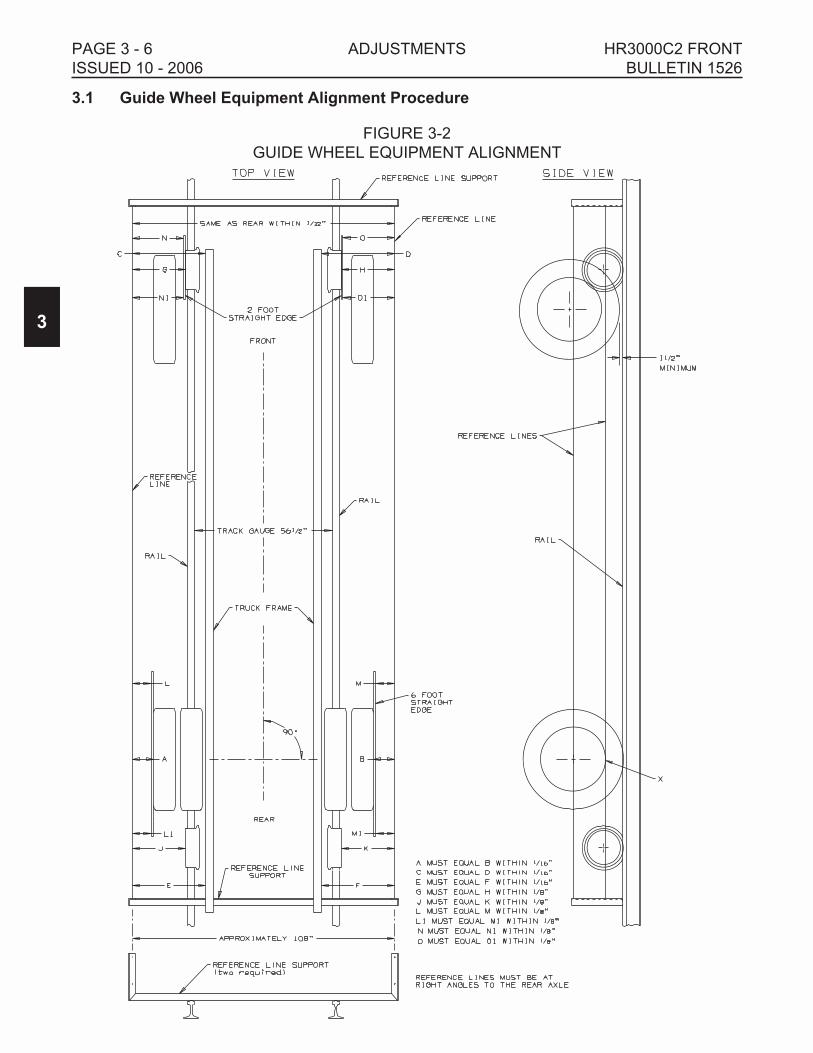
3.1.5 String Lining Set-Up - See Figure 3-2
1. The string lining procedure is only a guide to check and make alignment adjustments to
the guide wheel equipment. String lining the vehicle and guide wheel equipment will not
guarantee that the guide wheel equipped vehicle will track properly. Harsco Track
Technologies recommends that all HY-RAIL® equipped vehicles be track tested. The
vehicle should be at its normal operating load for track testing. The vehicle should be
track tested when:
a. The guide wheel equipment is installed on the vehicle.
b. Any adjustments are made to the guide wheel equipment.
c. The load on the vehicle is changed.
d. Periodically to ensure that the vehicle is tracking properly.
2. Lower and lock both the front and rear guide wheel units in the "rail" position. See
Operation Section - Placing Vehicle On Track. Set the vehicle wheels straight ahead.
Secure the vehicle steering wheel using the steering lock.
3. Establish parallel reference lines on each side of the vehicle as shown in Figure 3-2.
Parallel reference lines can be established by building two supports or brackets. These
can be built out of scrap angle iron or other material. The supports must be high enough
so the top reference line is through the center of the rear axle. The supports need to be a
few inches longer than the width of the vehicle. Wires or cords stretched between the
front and rear supports will be the reference lines. The wires or cords should be spaced
approximately 108 inches (2743 mm) apart. The distance between the wires or cords
must be equal or within 1/32 inch (.8 mm) at each support.
4. Clamp the supports to the rail in front of and behind the vehicle. The supports should be
at right angles to the rail. Stretch the wires or cords between the supports, so the lower
reference line is level with the bottom edge of the rear vehicle wheel rim(s) (point X) and
the upper reference line is through the center of the rear axle(s). The reference lines must
be level.
5. Shift the supports on the rail until dimension A equals (=) B and dimension C equals (=) D
or within 1/16 inch (1.6 mm). Measurements A and B should be taken from the edge of
the rear vehicle rim(s) directly below the axle (point X) to the reference lines.
Measurements C and D are taken from the front of the vehicle frame. When shifting the
supports, keep them at right angles to the rail so the reference lines stay level and parallel
to each other.
6. Hold a six (6) foot straight edge against the outer edge of the rear, outside tires with the
straight edge centered on the tires. Record dimensions L, L1, M and M1 to the reference
line. Rotate the rear tires 180 degrees and record a second set of dimensions at L, L1, M
and M1. Average the two dimensions taken at L, L1, M and M1.
Example: [ L (first dimension) + L (second dimension)] ÷ 2 = L (average dimension)
3
HR3000C2 FRONT ADJUSTMENTS PAGE 3 - 7
BULLETIN 1526 ISSUED 10 - 2006

3.1 Guide Wheel Equipment Alignment Procedure
3.1.5 String Lining Set-Up - See Figure 3-2
7. Shift the supports on the rail until dimension L (average) equals (=) M (average) and
dimension L1 (average) equals (=) M1 (average) or within 1/8 inch (3.2 mm). When
shifting the supports, keep them at right angles to the rail so the reference lines stay level
and parallel to each other. The reference lines will be parallel only when the rear axle is
straight.
8. After the reference lines have been established, measurements can be taken from these
lines to the guide wheels to help ensure correct alignment.
3.1.6 Guide Wheel Alignment
3.1.6.1 Checking Guide Wheel Side to Side Alignment - See Figure 3-2
1. Take measurements G and H. Measure from the outer edge of the guide wheel, directly
below the center line of the wheel spindle, to the reference lines. Check that dimension G
equals (=) H or is within 3/16 inch (4.8 mm). If not, determine the amount of side to side
adjustment that will be required.
3.1.6.2 Adjusting Guide Wheel Side to Side Alignment - See Figures 3-2, 3-3
1. Move the control valve handle to raise the guide wheels until all weight of the vehicle is
removed from the guide wheel unit. Let the guide wheels rest on the rails.
2. Make sure the parking brakes are applied. Stop the vehicle engine.
3. Adjustment is accomplished by loosening the eight axle mounting fasteners (1) and
moving the axle (2). The mounting plates on the axle are slotted for side to side
adjustment.
Note: The axle mounting plates on the wheel arms are slotted for forward and rearwardadjustment. Make sure when moving the axle side to side that the axle forward /rearward position does not change.
4. Adjust the side to side alignment of the front guide wheel unit (dimensions G and H are
equal or within 3/16 inch).
a. If dimension G is greater than dimension H, move the axle to the left one-half (1/2) of
the measured difference between G and H.
b. If dimension H is greater than dimension G, move the axle to the right one-half (1/2) of
the measured difference between G and H.
5. Tighten the eight axle mounting fasteners (1) securely.
6. Start the vehicle engine. Lower the guide wheels to the rail position.
3
PAGE 3 - 8 ADJUSTMENTS HR3000C2 FRONT
ISSUED 10 - 2006 BULLETIN 1526

3.1 Guide Wheel Equipment Alignment Procedure
3.1.6 Guide Wheel Alignment
3.1.6.2 Adjusting Guide Wheel Side to Side Alignment
7. Recheck measurements G and H. Check that dimension G equals (=) H or is within 3/16
inch (4.8 mm). If not, repeat the procedure until dimension G equals (=) H or is within 3/16
inch (4.8 mm).
3
HR3000C2 FRONT ADJUSTMENTS PAGE 3 - 9
BULLETIN 1526 ISSUED 10 - 2006
FIGURE 3-3
GUIDE WHEEL ALIGNMENT
RIGHT SIDE
"H"
LEFT SIDE
"G"
3.1 Guide Wheel Equipment Alignment Procedure
3.1.6 Guide Wheel Alignment
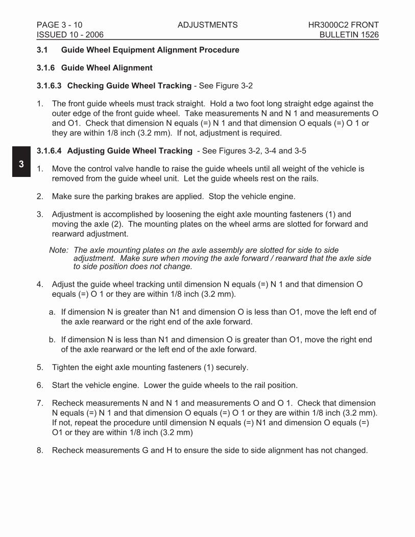
3.1.6.3 Checking Guide Wheel Tracking - See Figure 3-2
1. The front guide wheels must track straight. Hold a two foot long straight edge against the
outer edge of the front guide wheel. Take measurements N and N 1 and measurements O
and O1. Check that dimension N equals (=) N 1 and that dimension O equals (=) O 1 or
they are within 1/8 inch (3.2 mm). If not, adjustment is required.
3.1.6.4 Adjusting Guide Wheel Tracking - See Figures 3-2, 3-4 and 3-5
1. Move the control valve handle to raise the guide wheels until all weight of the vehicle is
removed from the guide wheel unit. Let the guide wheels rest on the rails.
2. Make sure the parking brakes are applied. Stop the vehicle engine.
3. Adjustment is accomplished by loosening the eight axle mounting fasteners (1) and
moving the axle (2). The mounting plates on the wheel arms are slotted for forward and
rearward adjustment.
Note: The axle mounting plates on the axle assembly are slotted for side to sideadjustment. Make sure when moving the axle forward / rearward that the axle sideto side position does not change.
4. Adjust the guide wheel tracking until dimension N equals (=) N 1 and that dimension O
equals (=) O 1 or they are within 1/8 inch (3.2 mm).
a. If dimension N is greater than N1 and dimension O is less than O1, move the left end of
the axle rearward or the right end of the axle forward.
b. If dimension N is less than N1 and dimension O is greater than O1, move the right end
of the axle rearward or the left end of the axle forward.
5. Tighten the eight axle mounting fasteners (1) securely.
6. Start the vehicle engine. Lower the guide wheels to the rail position.
7. Recheck measurements N and N 1 and measurements O and O 1. Check that dimension
N equals (=) N 1 and that dimension O equals (=) O 1 or they are within 1/8 inch (3.2 mm).
If not, repeat the procedure until dimension N equals (=) N1 and dimension O equals (=)
O1 or they are within 1/8 inch (3.2 mm)
8. Recheck measurements G and H to ensure the side to side alignment has not changed.
3
PAGE 3 - 10 ADJUSTMENTS HR3000C2 FRONT
ISSUED 10 - 2006 BULLETIN 1526

3.1 Guide Wheel Equipment Alignment Procedure
3.1.6 Guide Wheel Alignment
3
HR3000C2 FRONT ADJUSTMENTS PAGE 3 - 11
BULLETIN 1526 ISSUED 10 - 2006
FIGURE 3-5
GUIDE WHEEL ALIGNMENT
N1
N
O1
O
FIGURE 3-4
GUIDE WHEEL ALIGNMENT
RIGHT SIDE
"H"
LEFT SIDE
"G"
RIGHT SIDE LEFT SIDE

3.1 Guide Wheel Equipment Alignment Procedure
3.1.7 Vehicle Track Test
� CHECK AND CORRECT ALIGNMENT PROMPTLY IF MISALIGNMENT IS
INDICATED. MISALIGNMENT OF GUIDE WHEEL EQUIPMENT COULD
RESULT IN DERAILMENT OF THE VEHICLE AND SEVERE BODILY INJURY.
1. Harsco Track Technologies recommends that all HY-RAIL® equipped vehicles be track
tested. The vehicle should be at its normal operating load for track testing. The vehicle
should be track tested when:
a. The guide wheel equipment is installed on the vehicle.
b. Any adjustments are made to the guide wheel equipment.
c. The load on the vehicle is changed.
d. Periodically to ensure that the vehicle is tracking properly.
2. The vehicle must be placed on straight, level, tangent track. See Operation Section -
Placing Vehicle On Track.
3. Apply spray paint to the flanges and treads of all guide wheels.
4. Lower and lock both guide wheel units in the "rail" position.
5. Operate the vehicle a minimum of 1/4 mile at a normal operating speed.
6. The paint should wear evenly around the flanges and treads of all guide wheels. If the
paint is worn evenly on all guide wheels, the vehicle and guide wheel equipment is
properly aligned.
7. If the paint wore off the right front guide wheel flange and not off the left front guide wheel
flange, the guide wheel unit is "flanging right".
a. Raise the guide wheel unit from the "rail" position. Let the guide wheels rest on the rail.
See Adjusting Guide Wheel Tracking. Slightly move the right side of the guide wheel
unit forward or the left side of the guide wheel unit rearward.
b. Repaint the flanges and treads on all guide wheels. Lower and lock the guide wheel
unit in the "rail" Position. Operate the vehicle a minimum of 1/4 mile at a normal
operating speed. If the paint is worn evenly on all guide wheels, the vehicle and guide
wheel equipment is properly aligned.
c. If the paint continues to wear off the right front guide wheel flange and not off the left
front guide wheel flange, repeat Steps a. and b.
3
PAGE 3 - 12 ADJUSTMENTS HR3000C2 FRONT
ISSUED 10 - 2006 BULLETIN 1526
WARNING

3.1 Guide Wheel Equipment Alignment Procedure
3.1.7 Vehicle Track Test
8. If the paint wore off the left front guide wheel flange and not off the right front guide wheel
flange, the guide wheel unit is "flanging left".
a. Raise the guide wheel unit from the "rail" position. Let the guide wheels rest on the rail.
See Adjusting Guide Wheel Tracking. Slightly move the left side of the guide wheel unit
forward or the right side of the guide wheel unit rearward.
b. Repaint the flanges and treads on all guide wheels. Lower and lock the guide wheels
in the "rail" Position. Operate the vehicle a minimum of 1/4 mile at a normal operating
speed. If the paint is worn evenly on all guide wheels, the vehicle and guide wheel
equipment is properly aligned.
c. If the paint continues to wear off the left front guide wheel flange and not off the right
front guide wheel flange, repeat Steps a. and b.
9. If the preceding procedure did not correct the tracking problem, note which guide wheels,
flange and/or tread the paint is worn on.
a. Repaint the flanges and treads on all guide wheels.
b. Operate the vehicle in reverse for a short distance at a normal operating speed.
c. Note which guide wheels, flange and/or tread the paint is worn on.
If the paint wore off the right front flange when traveling forward and then off the left rear
flange when traveling in reverse or off the left front flange when traveling forward and
then off the right rear flange when traveling in reverse, the vehicle is probably not
aligned properly. Have the frame checked for proper alignment. See Vehicle Check.
10. If the vehicle continues to track improperly, repeat the String Lining and Guide Wheel
Alignment Procedure.
3
HR3000C2 FRONT ADJUSTMENTS PAGE 3 - 13
BULLETIN 1526 ISSUED 10 - 2006

3.2 Adjustments
3.2.1 Checking Wheel Arm Angle - Rail Position - See Figure 3-6
1. Both wheel arms need to be set to 20° ± 1° rearward from vertical to provide the proper
over-center position. Use an angle measuring device to check the angle on both wheel
arms. If both wheel arms are at 20° ± 1° rearward from vertical, they are set correctly. If
not, adjustment is required.
3.2.2 Adjusting Wheel Arm Angle - Rail Position - See Figure 3-6
1. Move the control valve handle to raise the guide wheels until all weight of the vehicle is
removed from the guide wheel unit. Let the guide wheels rest on the rails.
2. Make sure the parking brakes are applied. Stop the vehicle engine.
3. Adjustment is accomplished by adjusting set screws (2). There are two set screws on
each wheel arm. Loosen jam nut (1).
a. If the measured angle is less than 20° ± 1°, turn the set screws counter-clockwise.
b. If the measured angel is greater than 20° ± 1°, turn the set screw clockwise.
c. Adjust both set screws on the wheel arm equally. Tighten the jam nut.
4. Start the vehicle engine. Lower the guide wheels to the rail position.
5. Make sure both set screws are adjusted equally against the upper structure. Re-check the
angle of the wheel arms. If the wheel arms are at 20° ± 1° rearward from vertical, they are
set correctly. If not, repeat the procedure until the wheel arms are set correctly.
3
PAGE 3 - 14 ADJUSTMENTS HR3000C2 FRONT
ISSUED 10 - 2006 BULLETIN 1526
FIGURE 3-6
WHEEL ARM ANGLE - RAIL POSITION
SE024626-F

3.2 Adjustments
3.2.3 Checking Wheel Arm Stop - Highway Position - See Figure 3-7
1. The wheel arm stop set screws are used to adjust the the wheel arms when they are in the
"highway" position. The wheel arm set screws may need to be adjusted to ensure
clearance of guide wheel unit components and vehicle components when the unit is in the
"highway" position.
2. Slowly raise the guide wheels from the "rail" position. Visually observe the guide wheel
components to ensure they do not interfere with any vehicle components. The wheel arms
must also rest against the set screws to ensure the unit does not bounce when traveling
on the highway. If not, adjustment is required.
3.2.4 Adjusting Wheel Arm Stop - Highway Position - See Figure 3-7
1. Move the control valve handle to lower the guide wheels. Let the guide wheels rest on the
rails.
2. Make sure the parking brakes are applied. Stop the vehicle engine.
3. Adjustment is accomplished by adjusting set screws (2). There are two set screws on
each upper structure. Loosen jam nut (1).
a. To increase the guide wheel raise, turn the set screws counter-clockwise.
b. To decrease the guide wheel raise, turn the set screw clockwise.
c. Adjust both set screws on the wheel arm equally. Tighten the jam nut.
4. Start the vehicle engine. Lower the guide wheels to the rail position.
5. Make sure both set screws are adjusted equally against the wheel arm. Re-check the
guide wheel unit clearance to ensure it is acceptable. If not, repeat the procedure until the
clearance is acceptable.
3
HR3000C2 FRONT ADJUSTMENTS PAGE 3 - 15
BULLETIN 1526 ISSUED 10 - 2006
FIGURE 3-7
WHEEL ARM STOP - HIGHWAY POSITION
SE3409597-A

3.2 Adjustments
3.2.5 Checking Vehicle Front Tire Clearance - Rail Position - See Figure 3-8
The vehicle's front tire clearance should be checked whenever the vehicle is placed on rail or
whenever the load on the vehicle is changed significantly.
1. Place the vehicle on straight, level, tangent track. Place the vehicle automatic
transmission in "Park" or manual transmission in "Neutral". Apply the parking brake.
Lower both guide wheel units in the "rail" position. See Operation Section - Placing
Vehicle On Track.
2. When the front guide wheels are lowered and locked in the "rail" position, the guide wheel
unit suspension linkage will raise the vehicle's front tires above the rails. This is necessary
to ensure clearance when the vehicle passes through switches, turnouts, crossings, frogs,
etc. As the vehicle is loaded, the front tire clearance will decrease. The front tires must
always clear the top of the rails by a minimum of 1-1/2 inches (38 mm) whenever the
vehicle is on track. If not, adjustment is required.
3.2.6 Adjusting Vehicle Front Tire Clearance - Rail Position - See Figure 3-8
1. Determine the amount of shim that will be required to obtain the minimum of 1-1/2 inches
(38 mm) of tire clearance above the rail. As an example: if there is only 1 inch of
clearance, an additional 1/2 inch of shim will need to be added between the unit rear
mounts and the vehicle springs.
2. Move the control valve handle to raise the guide wheels to the "highway" position.
3. Make sure the parking brakes are applied. Stop the vehicle engine.
4. Place floor jack(s) and blocks under the rear of the guide wheel unit to prevent it from
falling. Also, the jack(s) are necessary to lower the rear of the unit to add shims and then
raise it back in place.
5. Loosen and remove the hex nuts (1) from the rod assembly (2). Remove the pads and
any shims (3) from above the springs.
6. Using the jack(s), lower the rear of the unit until the required number of shims (3) can be
added to the rod assembly.
7. Jack the rear of the unit back up until the shims are against the springs. Make sure that
the rod assemblies are located on the springs in the same position (same distance from
the vehicle axle) as they were before being removed.
8. Re-install the pad and any extra shims above the springs. Install the hex nuts and tighten
securely.
3
PAGE 3 - 16 ADJUSTMENTS HR3000C2 FRONT
ISSUED 10 - 2006 BULLETIN 1526
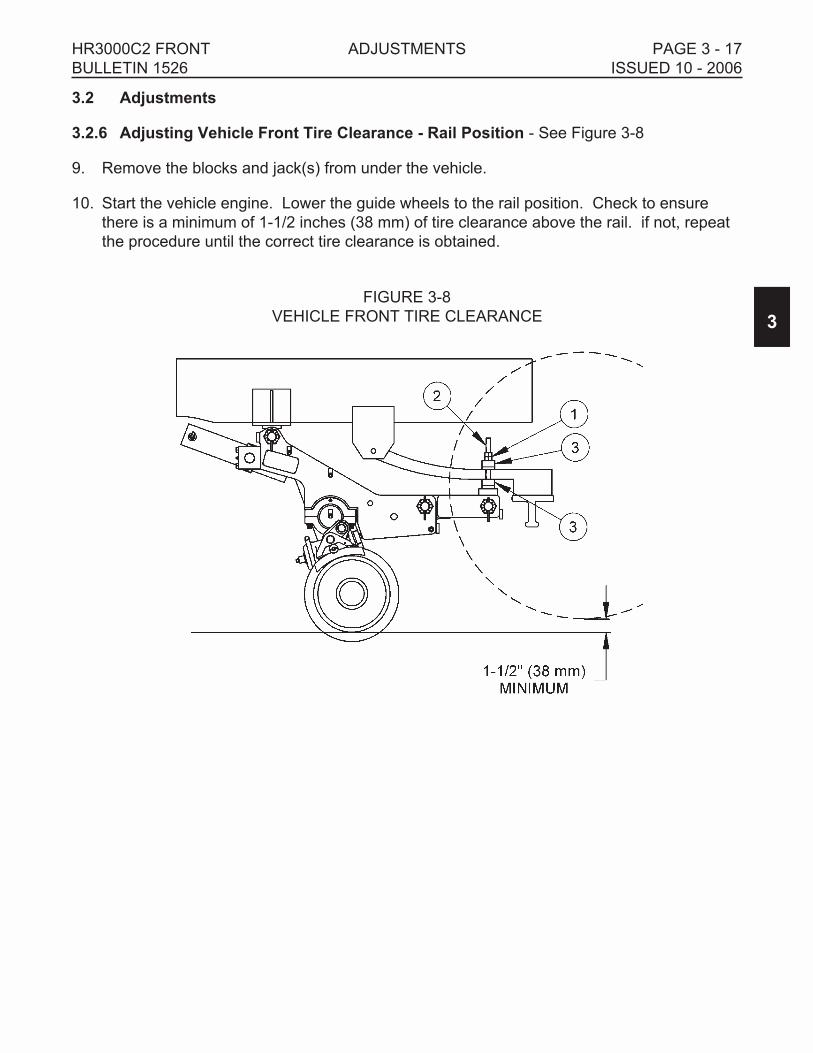
3.2 Adjustments
3.2.6 Adjusting Vehicle Front Tire Clearance - Rail Position - See Figure 3-8
9. Remove the blocks and jack(s) from under the vehicle.
10. Start the vehicle engine. Lower the guide wheels to the rail position. Check to ensure
there is a minimum of 1-1/2 inches (38 mm) of tire clearance above the rail. if not, repeat
the procedure until the correct tire clearance is obtained.
3
HR3000C2 FRONT ADJUSTMENTS PAGE 3 - 17
BULLETIN 1526 ISSUED 10 - 2006
FIGURE 3-8
VEHICLE FRONT TIRE CLEARANCE

3.2 Adjustments
3.2.7 Brake Shoe Clearance
3.2.7.1 Checking Brake Shoe Clearance - See Figure 3-9
1. Place the vehicle automatic transmission in "Park" or manual transmission in "Neutral".
Apply the parking brake.
2. Measure the clearance between the brake shoe and the guide wheel tread. The clearance
must not exceed 1/8 inch (3.2 mm), or adjustment is required.
3. Repeat Step 2 to check the brake shoe clearance on the other guide wheel brake.
3.2.7.2 Adjusting Checking Brake Shoe Clearance - See Figure 3-9
1. Remove the cotter pin from the pin (1). Remove the pin (1) from the yoke (2) on the brake
actuator (3). Loosen jam nut (4) and turn yoke (2) counter-clockwise to adjust the brake
shoe closer to the guide wheel tread or clockwise to adjust the brake shoe away from the
guide wheel tread.
2. Adjust so the brake shoe is 1/32 - 1/16 inch (.8 - 1.6 mm) away from the guide wheel
tread. Install the pin (1) through the yoke (2) and brake arm (5) and secure using the
cotter pin. Tighten jam nut (4) securely. Recheck the brake shoe clearance.
3. Repeat this procedure to adjust the brake shoe clearance on the other guide wheel brake.
3
PAGE 3 - 18 ADJUSTMENTS HR3000C2 FRONT
ISSUED 10 - 2006 BULLETIN 1526
FIGURE 3-9
BRAKE SHOE CLEARANCE

3.2 Adjustments
3.2.8 Rail Sweep Clearance
3.2.8.1 Checking Rail Sweep Clearance - See Figure 3-10
1. Place the vehicle on straight, level track. Place the vehicle automatic transmission in
"Park" or manual transmission in "Neutral". Apply the vehicle parking / emergency brake.
Lower and lock the front and rear guide wheels in the "rail" position.
2. The rubber rail sweeps should clear the top of the rail by 3/16 inch (4.8 mm). If not, see
Adjustment.
3.2.8.2 Adjusting Rail Sweep Clearance - See Figure 3-8
1. Loosen the two hex nuts (1) on cap screws (2). Slide the rubber sweep (3) down until it
clears the top of the rail by 3/16 inch (4.8 mm). Re-tighten the two hex nuts (1) and cap
screws (2).
2. Repeat this procedure to adjust the rail sweep clearance on the other guide wheel.
3. When the rubber sweep is worn so it cannot be adjusted, replace the rubber sweep (3).
3
HR3000C2 FRONT ADJUSTMENTS PAGE 3 - 19
BULLETIN 1526 ISSUED 10 - 2006
FIGURE 3-10
RAIL SWEEP CLEARANCE
SE97A122A-1
3/16"
1
2
3

NOTES
3
PAGE 3 - 20 ADJUSTMENTS HR3000C2 FRONT
ISSUED 10 - 2006 BULLETIN 1526
SECTION 4 - MAINTENANCE
TABLE OF CONTENTS
4.1 Maintenance Schedule. . . . . . . . . . . . . . . . . . . . . . . . . . . . . . . . . . . . . . . . . . . . . . 4 - 2
4.1.1 Daily . . . . . . . . . . . . . . . . . . . . . . . . . . . . . . . . . . . . . . . . . . . . . . . . . . . . . . . . . 4 - 2
4.1.2 Weekly . . . . . . . . . . . . . . . . . . . . . . . . . . . . . . . . . . . . . . . . . . . . . . . . . . . . . . . 4 - 2
4.1.3 At 2,000 Track Miles (3200 km) . . . . . . . . . . . . . . . . . . . . . . . . . . . . . . . . . . . . 4 - 3
4.1.4 At 10,000 Track Miles (16000 km) . . . . . . . . . . . . . . . . . . . . . . . . . . . . . . . . . . 4 - 3
4.2 Waste Disposal . . . . . . . . . . . . . . . . . . . . . . . . . . . . . . . . . . . . . . . . . . . . . . . . . . . 4 - 3
4.3 Guide Wheel Equipment Lubrication . . . . . . . . . . . . . . . . . . . . . . . . . . . . . . . . . . . 4 - 4
4.3.1 Guide Wheel Unit Lubrication . . . . . . . . . . . . . . . . . . . . . . . . . . . . . . . . . . . . . . 4 - 4
4.3.2 Re-Packing Guide Wheel Bearings. . . . . . . . . . . . . . . . . . . . . . . . . . . . . . . . . . 4 - 5
4.4 Guide Wheels. . . . . . . . . . . . . . . . . . . . . . . . . . . . . . . . . . . . . . . . . . . . . . . . . . . . . 4 - 6
4.4.1 Allowable Wear . . . . . . . . . . . . . . . . . . . . . . . . . . . . . . . . . . . . . . . . . . . . . . . . . 4 - 6
4.5 Vehicle Wheels. . . . . . . . . . . . . . . . . . . . . . . . . . . . . . . . . . . . . . . . . . . . . . . . . . . . 4 - 7
4.5.2 Tire Replacement . . . . . . . . . . . . . . . . . . . . . . . . . . . . . . . . . . . . . . . . . . . . . . . 4 - 7
4.6 Bolt Torque Requirements . . . . . . . . . . . . . . . . . . . . . . . . . . . . . . . . . . . . . . . . . . . 4 - 7
4.7 Hoses And Fittings . . . . . . . . . . . . . . . . . . . . . . . . . . . . . . . . . . . . . . . . . . . . . . . . . 4 - 8
4.7.1 Inspection, Maintenance, Replacement And Installation. . . . . . . . . . . . . . . . . . 4 - 8
4.7.2 Hose Band . . . . . . . . . . . . . . . . . . . . . . . . . . . . . . . . . . . . . . . . . . . . . . . . . . . . 4 - 8
4
HR3000C2 FRONT MAINTENANCE PAGE 4 - 1
BULLETIN 1526 ISSUED 10 - 2006

4.1 Maintenance Schedule
� RE-TORQUE VEHICLE WHEEL LUG NUTS AND GUIDE WHEEL LUG NUTS
AFTER THE FIRST 50 MILES OF OPERATION. THEREAFTER TORQUE
WHEEL LUG NUTS ACCORDING TO VEHICLE MANUFACTURER'S WHEEL
TORQUE SPECIFICATIONS. FAILURE TO COMPLY COULD RESULT IN
SEVERE BODILY INJURY.
4.1.1 Daily
1. Inspect the front and rear guide wheel units for damaged, worn or missing parts.
2. Check the mechanical and hydraulic locks and lock pins for ease of operation.
3. Check the hydraulic reservoir to ensure that the oil level is full. If low, fill to the proper
level with the correct fluid.
4. When the vehicle is operated on the track, listen for unusual noises. Unusual noises may
indicate incorrectly lowered guide wheels, damaged or missing parts, or insufficient
lubrication. Pay attention to the quality of the ride. Check the guide wheel equipment
alignment if the vehicle crowds one side of the track instead of floating from side to side.
See Adjustments - Guide Wheel Equipment Alignment Procedure.
4.1.2 Weekly
1. Check the guide wheel equipment alignment. See Adjustment Section, Guide Wheel
Equipment Alignment Procedure - Vehicle Track Test.
2. Inspect the guide wheel tread and flanges for wear or damage. See Maintenance - Guide
Wheel Allowable Wear.
3. Spin each guide wheel by hand, checking for ease of rotation. If the guide wheel does not
rotate easily, the guide wheel bearings may be lacking lubrication or may be damaged.
Inspect, re-pack or replace the bearings if necessary.
4. Inspect the vehicle wheels, studs, lug nuts and tires for wear, damage, cuts etc.
5. Check the vehicle tires for correct inflation pressure. Operate at the tire manufacturer's
recommended maximum pressure printed on the sidewalls of the tires, or the wheel
manufacturer's recommended maximum pressure stamped on the wheel, whichever is
lower.
6. Check all bolts for tightness. See Appendix A for bolt torque specification tables and
grade identification markings used by manufacturers.
4
PAGE 4 - 2 MAINTENANCE HR3000C2 FRONT
ISSUED 10 - 2006 BULLETIN 1526
WARNING

4.1 Maintenance Schedule
4.1.3 Every 2,000 Track Miles (3200 km):
Lubricate the guide wheel unit locations provided with grease fittings. See Guide Wheel
Equipment Lubrication.
4.1.4 At 10,000 Track Miles (16000 km):
Re-pack and adjust the guide wheel bearings. See Re-packing Guide Wheel Bearings.
4.2 Waste Disposal
Dispose of waste properly. Improper disposal of waste can threaten the
environment. The operation and maintenance of Harsco Track Technologies
equipment may involve the use of such items as hydraulic oil, engine oil, fuel,
coolant, brake fluid, filters, batteries, etc.
Use leak proof containers when draining fluids. Do not pour waste onto the
ground, down a drain, or into any water source. Inquire on the proper way to
recycle or dispose of waste according to applicable Federal, State and/or local
regulations.
4
HR3000C2 FRONT MAINTENANCE PAGE 4 - 3
BULLETIN 1526 ISSUED 10 - 2006
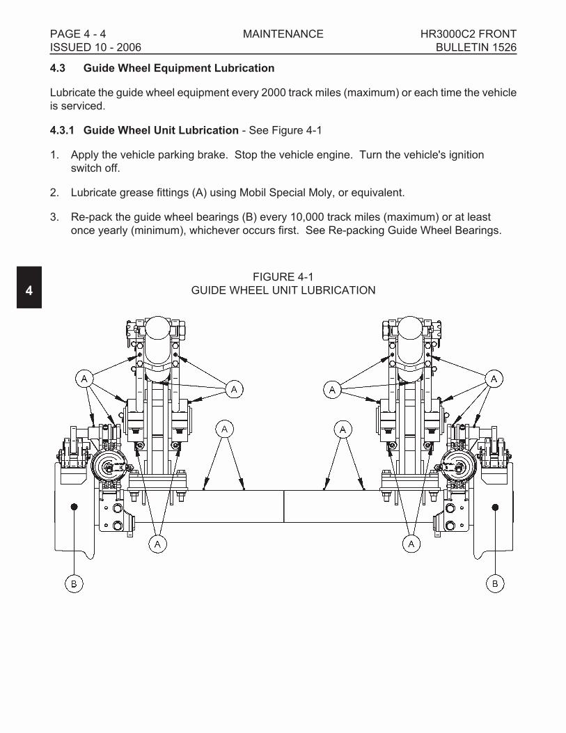
4.3 Guide Wheel Equipment Lubrication
Lubricate the guide wheel equipment every 2000 track miles (maximum) or each time the vehicle
is serviced.
4.3.1 Guide Wheel Unit Lubrication - See Figure 4-1
1. Apply the vehicle parking brake. Stop the vehicle engine. Turn the vehicle's ignition
switch off.
2. Lubricate grease fittings (A) using Mobil Special Moly, or equivalent.
3. Re-pack the guide wheel bearings (B) every 10,000 track miles (maximum) or at least
once yearly (minimum), whichever occurs first. See Re-packing Guide Wheel Bearings.
4
PAGE 4 - 4 MAINTENANCE HR3000C2 FRONT
ISSUED 10 - 2006 BULLETIN 1526
FIGURE 4-1
GUIDE WHEEL UNIT LUBRICATION

4.3 Guide Wheel Equipment Lubrication
4.3.2 Re-Packing Guide Wheel Bearings - See Figure 4-2
Re-pack the guide wheel bearings every 10,000 track miles (maximum) or at least once yearly
(minimum), whichever occurs first.
1. Apply the parking brake. Raise and lock the front and rear guide wheel units in the
"highway" position. Stop the vehicle engine. Shut off the vehicle ignition switch.
2. Remove the hub cap (1). Remove the 3/16 x 2-1/2 inch cotter pin (2), 1-1/2 inch castle nut
(3) and spindle washer (4).
3. Pull the guide wheel (5) from the spindle (6). Remove the outer bearing cone (7) from the
guide wheel (5). Remove the grease seal (11) and inner bearing cone (9) from the guide
wheel (5).
4. Clean all components of old grease and dirt.
5. Inspect the spindle, bearing cones and cups (7 & 8, 9 & 10) for nicks, gouges and wear. If
any of these are evident, replace the component.
6. Measure the guide wheel wear. See Maintenance - Guide Wheels, Allowable Wear.
7. Coat the spindle surface, grease seal surface, both bearing cup surfaces, pack both
bearing cones and fill the guide wheel cavity 1/2 full (50 %) using Mobil HP grease, or
equivalent.
8. Install the inner bearing cone (9) into the guide
wheel (5). Install a new grease seal (11) into
the wheel.
9. Slide the guide wheel (5) with the inner bearing
(9) and grease seal (11) onto the spindle (6).
Install the outer bearing cone (7), spindle
washer (4) and 1-1/2 inch castle nut (3) onto the
spindle (6).
10. Torque the castle nut (3) to approximately 20 ft
lbs. Then loosen the castle nut. This is
especially important if new bearing cups have
been installed.
11. Torque the castle nut (3) to 7 ft lbs (zero
clearance). Then back the castle nut off 1/2 to 1
flat of the nut (.001 - .010 inch clearance).
Secure the castle nut using a new cotter pin (2).
12. Install the hub cap (1) onto the guide wheel.
4
HR3000C2 FRONT MAINTENANCE PAGE 4 - 5
BULLETIN 1526 ISSUED 10 - 2006
FIGURE 4-2
RE-PACKING GUIDE WHEEL
BEARINGS
SE97A124A-1

4.4 Guide Wheels
4.4.1 Allowable Wear - See Figure 4-3
� REPLACE ANY GUIDE WHEEL IMMEDIATELY WHICH SHOWS DAMAGE
AND/OR HAS WORN MORE THAN THE ALLOWABLE LIMITS. FAILURE TO
COMPLY COULD RESULT IN DERAILMENT OF THE VEHICLE, AND SEVERE
BODILY INJURY.
The guide wheels must be checked for allowable wear a minimum of once yearly (every twelve
months). Use the following procedure to check the guide wheel wear.
1. Tools needed: Harsco Track Technologies wheel caliper (M019889), or equivalent.
2. Measure the guide wheel flange at Position "A" with the wheel caliper. The minimum
allowable flange dimension at Position "A" is 7/8 inch (22.2 mm).
If the guide wheel flange dimension is less than the allowable limit, replace the guide
wheel immediately.
3. Measure the guide wheel tread at Position "B" with the wheel caliper. The minimum
allowable tread dimension at Position "B" is 1/2 inch (12.7 mm).
If the guide wheel tread dimension is less than the allowable limit, replace the guide wheel
immediately.
4. The entire guide wheel must not have any gouges or cracks. If any of these are evident,
replace the guide wheel immediately.
4
PAGE 4 - 6 MAINTENANCE HR3000C2 FRONT
ISSUED 10 - 2006 BULLETIN 1526
WARNING
FIGURE 4-3
ALLOWABLE GUIDE WHEEL WEAR
SE93A124A-1

4.5 Vehicle Wheels
4.5.1 Tire Replacement
� USE REPLACEMENT TIRES WITH THE SAME ROLLING RADIUS, TREAD
WIDTH, PLY RATING, AND LOAD RATING AS RECOMMENDED BY THE
VEHICLE MANUFACTURER. FAILURE TO COMPLY COULD RESULT IN
BODILY INJURY AND/OR PROPERTY DAMAGE.
Replacement tires must have the same rolling radius, tread width, ply rating, and load rating as
recommended by the vehicle manufacturer. Using tires of equal diameter will help keep the
speedometer reading and the guide wheel load accurate. Tires must have a minimum 6-1/2
inches of tread width. After installing new tire(s) on the vehicle, check guide wheel load. See the
Adjustment Section - Guide Wheel Equipment Alignment Procedure.
Inflate tires to the tire manufacturer's recommended maximum pressure printed on the sidewalls
of the tires or the wheel manufacturer's recommended maximum pressure stamped on the wheel,
whichever is lower. The wheels and tires should be static balanced or balanced after installation
on the vehicle for the best results. Torque vehicle wheel lug nuts to manufacturer's recommended
specifications.
4.6 Bolt Torque Requirements
� CHECK ALL BOLTS AND NUTS PERIODICALLY. KEEP BOLTS AND NUTS
TIGHTENED TO THE TORQUE SPECIFIED IN APPENDIX A. IF BOLT
REPLACEMENT BECOMES NECESSARY, REPLACE WORN BOLT WITH
EQUAL S.A.E. GRADE NUMBER BOLT. FAILURE TO COMPLY COULD
RESULT IN BODILY INJURY, AND/OR PROPERTY DAMAGE.
See Appendix A for bolt torque specification tables and grade identification markings used by
manufacturers.
4
HR3000C2 FRONT MAINTENANCE PAGE 4 - 7
BULLETIN 1526 ISSUED 10 - 2006
CAUTION
CAUTION

4.7 Hoses and Fittings
� ALL HOSES AND FITTINGS ON THIS EQUIPMENT MUST COMPLY WITH SAE
STANDARD J1273 RECOMMENDED PRACTICE FOR SELECTION,
INSTALLATION AND MAINTENANCE OF HOSE AND HOSE ASSEMBLIES.
FAILURE TO COMPLY TO THIS STANDARD COULD RESULT IN SEVERE
BODILY INJURY.
4.7.1 Inspection, Maintenance, Replacement And Installation
The inspection, maintenance, replacement and installation of hydraulic hose assemblies and
fittings on this equipment must conform with SAE Standard J1273. See Appendix B.
4.7.1 Hose Band - See Figure 4-4
All Harsco Track Technologies original and replacement hose assemblies manufactured for this
equipment at the Harsco Track Technologies, Harsco Corporation Fairmont, Minnesota plant
facility are supplied with a hose band displaying the date of manufacture and the Harsco Track
Technologies part number. The hose assembly illustrated in the example was manufactured in
May 2006 and is Harsco Track Technologies part number 188662.
4
PAGE 4 - 8 MAINTENANCE HR3000C2 FRONT
ISSUED 10 - 2006 BULLETIN 1526
WARNING
188662HARSCO TRACKTECHNOLOGIESPART NUMBER
JANUARYFEBRUARYMARCHAPRILMAYJUNEJULYAUGUSTSEPTEMBEROCTOBERNOVEMBERDECEMBER
= 1= 2= 3= 4= 5= 6= 7= 8= 9= 0= N= D
MONTH YEARLAST TWO DIGITSOF THE YEAR OFMANUFACTURE
5 06
50
6
FIGURE 4-4
HOSE BAND

SECTION 5 - TROUBLESHOOTING
TABLE OF CONTENTS
5.1 Troubleshooting Guide Wheel Equipment . . . . . . . . . . . . . . . . . . . . . . . . . . . . . . . 5 - 2
5
HR3000C2 FRONT TROUBLESHOOTING PAGE 5 - 1
BULLETIN 1526 ISSUED 10 - 2006

5.1 Troubleshooting Guide Wheel Equipment
PROBLEM PROBABLE CAUSE POSSIBLE REMEDY
Hydraulic pump not
delivering oil.
Mechanical PTO not engaged
or control valve not shifted to
direct oil flow to guide wheel
equipment.
Engage mechanical PTO.
Shift control valve to direct oil
flow to guide wheel
equipment.
Switch for auxiliary electric
powered hydraulic pump in
OFF position.
Move switch to ON position.
Hydraulic reservoir oil level
low.
Fill reservoir to full level with
recommended hydraulic oil.
Oil restricted to pump intake. Check all strainers and filters
for dirt and sludge. Clean and
replace if necessary.
Components bent, broken,
worn, etc.
Replace components.
Guide wheel unit does not
lower or raise.
Lock pins engaged. Disengage lock pins. See
Operation Section - Placing
Vehicle On Track or
Removing Vehicle From
Track.
Hydraulic pump not operating. Start hydraulic pump.
Hydraulic reservoir oil level
low.
Fill reservoir to full level with
recommended hydraulic oil.
Components bent, broken,
worn, etc.
Replace components.
Guide wheel unit is difficult
to lower or raise.
Vehicle over-loaded. Remove excess load from
vehicle.
Components bent, broken,
worn, etc.
Replace components.
Lock will not engage when
guide wheel unit is in
"highway" position.
Components bent, broken,
worn, etc.
Replace components.
5
PAGE 5 - 2 TROUBLESHOOTING HR3000C2 FRONT
ISSUED 10 - 2006 BULLETIN 1526

5.1 Troubleshooting Guide Wheel Equipment
PROBLEM PROBABLE CAUSE POSSIBLE REMEDY
Vehicle load exceeds front
Guide wheel unit
maximum rated load.
Vehicle overloaded. Redistribute or remove some
of the load.
Vehicle front tires clear rail
less than 1-1/2" (38 mm)
when vehicle is on track
and loaded.
Vehicle overloaded. Redistribute or remove some
of the load.
Guide wheel unit not adjusted
properly.
See Adjustment Section -
Checking Vehicle Front Tire
Clearance - Rail Position.
Vehicle derails. Guide wheel units, vehicle
rear axle, etc. not aligned with
vehicle frame.
Check alignment. See
Adjustment Section - Guide
Wheel Equipment Alignment
Procedure.
Vehicle pulls noticeably to
the left or right when on
track.
Vehicle loaded heavy on one
side.
Move load to center of
vehicle.
Guide wheel units, vehicle
rear axle, etc. not aligned with
vehicle frame.
Check alignment. See
Adjustment Section - Guide
Wheel Equipment Alignment
Procedure.
Incorrect or worn vehicle rear
tire.
Check for correct rear tire.
Replace if necessary.
Replace worn rear tire.
Vehicle rear tires under
inflated.
Check pressure. Inflate if low.
Do not exceed tire
manufacturer's recommended
maximum pressure printed on
the sidewalls, or wheel
manufacturer's recommended
maximum pressure stamped
on the wheel, whichever is
lower.
Guide wheel brake shoes
dragging.
Re-adjust brake shoes. See
Adjustment Section - Brake
Shoe Clearance.
5
HR3000C2 FRONT TROUBLESHOOTING PAGE 5 - 3
BULLETIN 1526 ISSUED 10 - 2006

5.1 Troubleshooting Guide Wheel Equipment
PROBLEM PROBABLE CAUSE POSSIBLE REMEDY
Vibration felt in the vehicle
when traveling on track.
Guide wheel units mounting
fasteners loose.
Tighten all bolts to
recommended torque.
Guide wheel bearings worn. Replace bearings, wheel or
axle.
Guide wheels worn. Check guide wheel wear. See
Maintenance Section - Guide
Wheels, Allowable Wear.
Vehicle rear rim bent. Replace. See vehicle
manufacturer.
Vehicle rear tires out of
balance.
Balance tires.
Vibration felt in the vehicle
when traveling on
highway.
Guide wheel units mounting
fasteners loose.
Tighten all bolts to
recommended torque.
Guide wheel units not locked
in "highway" position.
STOP IMMEDIATELY. Make
sure both guide wheel units
are locked in "highway"
position.
Vehicle rim bent. Replace. See vehicle
manufacturer.
Vehicle tires out of balance. Balance tires.
5
PAGE 5 - 4 TROUBLESHOOTING HR3000C2 FRONT
ISSUED 10 - 2006 BULLETIN 1526

SECTION 6 - PARTS
TABLE OF CONTENTS
SERIAL NUMBERS . . . . . . . . . . . . . . . . . . . . . . . . . . . . . . . . . . . . . . . . . . . . . . . . . . . . . 6 - 2
INSTRUCTIONS FOR ORDERING PARTS . . . . . . . . . . . . . . . . . . . . . . . . . . . . . . . . . . . 6 - 3
GUIDE WHEEL UNIT - 202600 . . . . . . . . . . . . . . . . . . . . . . . . . . . . . . . . . . . . . . . . . . . . 6 - 4
GUIDE WHEEL ASSEMBLY. . . . . . . . . . . . . . . . . . . . . . . . . . . . . . . . . . . . . . . . . . . . . . . 6 - 8
STEERING LOCK GROUPS . . . . . . . . . . . . . . . . . . . . . . . . . . . . . . . . . . . . . . . . . . . . . . 6 - 8
MANUAL LOCK GROUP - 203174 . . . . . . . . . . . . . . . . . . . . . . . . . . . . . . . . . . . . . . . . . . 6 - 9
HYDRAULIC LOCK GROUP - 203175 . . . . . . . . . . . . . . . . . . . . . . . . . . . . . . . . . . . . . . . 6 - 10
RAIL SWEEP GROUP - 203193. . . . . . . . . . . . . . . . . . . . . . . . . . . . . . . . . . . . . . . . . . . . 6 - 12
TRUCK BRAKE CONNECTION - 162114 . . . . . . . . . . . . . . . . . . . . . . . . . . . . . . . . . . . . 6 - 14
HYDRAULIC POWER PACK, FULL - 137926 . . . . . . . . . . . . . . . . . . . . . . . . . . . . . . . . . 6 - 16
HYDRAULIC POWER PACK, ABBREVIATED - 137927 . . . . . . . . . . . . . . . . . . . . . . . . . 6 - 20
WHEEL LOAD JACK - 159510 . . . . . . . . . . . . . . . . . . . . . . . . . . . . . . . . . . . . . . . . . . . . . 6 - 22
SIGHT ROD EXTENSION GROUP - 164574 . . . . . . . . . . . . . . . . . . . . . . . . . . . . . . . . . . 6 - 23
DECAL SERVICE GROUP - 203157 . . . . . . . . . . . . . . . . . . . . . . . . . . . . . . . . . . . . . . . . 6 - 23
MOUNTING BRACKET GROUPS
203214. . . . . . . . . . . . . . . . . . . . . . . . . . . . . . . . . . . . . . . . . . . . . . . . . . . . . . . . . . . . . 6 - 24
3409597. . . . . . . . . . . . . . . . . . . . . . . . . . . . . . . . . . . . . . . . . . . . . . . . . . . . . . . . . . . . 6 - 24
3410281. . . . . . . . . . . . . . . . . . . . . . . . . . . . . . . . . . . . . . . . . . . . . . . . . . . . . . . . . . . . 6 - 24
6
HR3000C2 FRONT PARTS PAGE 6 - 1
BULLETIN 1526 ISSUED 10 - 2006

Serial Numbers
When this bulletin is received, complete the following record from the serial number tag on the
front guide wheel unit. Always mention these factory serial numbers when calling or writing about
the unit. The serial number tag is located on the frame assembly of the unit.
6
PAGE 6 - 2 PARTS HR3000C2 FRONT
ISSUED 10 - 2006 BULLETIN 1526
FRONT GUIDE WHEEL UNIT SERIAL NUMBER

Instructions For Ordering Parts
1. See Section 7 for the Vehicle Application charts.
2. Find the chart for the make, model and year of the vehicle that the unit is mounted on.
3. Each application consists of required groups, optional groups required and accessory
group options. These are the group numbers that were supplied with, or that were
available for the unit.
4. Locate the appropriate group numbers in the Parts Section to find the individual parts
required.
5. Front - rear and left - right are determined from the operator's position.
6. Assemblies: Items listed in CAPITALS are assemblies which include all parts listed
immediately following and indented to the right. When assemblies can be used, always
order them to save work of fitting separate parts.
7. For convenience in ordering, parts are listed by item number, part number, description,
and quantity in each assembly or group. If in doubt as to any part wanted, send full
description, sketch, or send the old part with the order.
8. To insure prompt and correct shipment of parts on orders, always give:
a. Quantity of each part wanted.
b. Part number of each part as shown in this book. Include any prefix and suffix letters.
c. Description of each part as shown in this book.
d. Factory serial numbers recorded above.
e. Purchase order number (if required).
f. Preferred method of shipment.
9. All parts are shipped F.O.B. factory, transportation charges to be paid by customer.
Terms to be determined by the Credit Department.
6
HR3000C2 FRONT PARTS PAGE 6 - 3
BULLETIN 1526 ISSUED 10 - 2006

202600 GUIDE WHEEL UNIT
6
PAGE 6 - 4 PARTS HR3000C2 FRONT
ISSUED 10 - 2006 BULLETIN 1526
SE202600-E-1

202600 GUIDE WHEEL UNIT
6
HR3000C2 FRONT PARTS PAGE 6 - 5
BULLETIN 1526 ISSUED 10 - 2006
SE202600-E-2

202600 GUIDE WHEEL UNIT
ITEM PART NO DESCRIPTION QTY
1 065824 Washer. . . . . . . . . . . . . . . . . . . . . . . . . . . . . . . . . . . . . . . . . . . . . . . . . 4
2 070238 Pin . . . . . . . . . . . . . . . . . . . . . . . . . . . . . . . . . . . . . . . . . . . . . . . . . 2
3 126846 Pin . . . . . . . . . . . . . . . . . . . . . . . . . . . . . . . . . . . . . . . . . . . . . . . . . 2
4 136922K Brake Shoe Holder. . . . . . . . . . . . . . . . . . . . . . . . . . . . . . . . . . . . . . . . 2
5 202067 Washer. . . . . . . . . . . . . . . . . . . . . . . . . . . . . . . . . . . . . . . . . . . . . . . . 24
6 202576 UPPER STRUCTURE, RIGHT. . . . . . . . . . . . . . . . . . . . . . . . . . . . . . . 1
202579 Trunnion Block . . . . . . . . . . . . . . . . . . . . . . . . . . . . . . . . . . . . . . . . 1
F021862 Cap Screw, 1/2-13 x 5" Hex Hd . . . . . . . . . . . . . . . . . . . . . . . . . . . 4
7 202582 Cross Tube. . . . . . . . . . . . . . . . . . . . . . . . . . . . . . . . . . . . . . . . . . . . . . 2
8 202598 Axle Assembly (includes slotted nuts and cotter pins) . . . . . . . . . . . . . 1
9 202599 HYDRAULIC CYLINDER . . . . . . . . . . . . . . . . . . . . . . . . . . . . . . . . . . . 2
202607 Seal Kit . . . . . . . . . . . . . . . . . . . . . . . . . . . . . . . . . . . . . . . . . . . . . . 1
10 202609 Pin . . . . . . . . . . . . . . . . . . . . . . . . . . . . . . . . . . . . . . . . . . . . . . . . . 2
11 202627 Mounting Block, Front . . . . . . . . . . . . . . . . . . . . . . . . . . . . . . . . . . . . . 2
12 202632 Mounting Block, Rear. . . . . . . . . . . . . . . . . . . . . . . . . . . . . . . . . . . . . . 2
13 202653 Pin . . . . . . . . . . . . . . . . . . . . . . . . . . . . . . . . . . . . . . . . . . . . . . . . . 4
14 203542 Spacer, 1" . . . . . . . . . . . . . . . . . . . . . . . . . . . . . . . . . . . . . . . . . . . . . . 2
15 203543 Spacer, 1/2" . . . . . . . . . . . . . . . . . . . . . . . . . . . . . . . . . . . . . . . . . . . . . 2
16 203731 UPPER STRUCTURE, LEFT . . . . . . . . . . . . . . . . . . . . . . . . . . . . . . . . 1
202579 Trunnion Block . . . . . . . . . . . . . . . . . . . . . . . . . . . . . . . . . . . . . . . . 1
F021862 Cap Screw, 1/2-13 x 5" Hex Hd . . . . . . . . . . . . . . . . . . . . . . . . . . . 4
17 3409092 Brake Arm, Left . . . . . . . . . . . . . . . . . . . . . . . . . . . . . . . . . . . . . . . . . . 1
18 3409093 Brake Arm, Right . . . . . . . . . . . . . . . . . . . . . . . . . . . . . . . . . . . . . . . . . 1
19 3409101 Brake Tower, Left . . . . . . . . . . . . . . . . . . . . . . . . . . . . . . . . . . . . . . . . . 1
20 3409102 Brake Tower, Right . . . . . . . . . . . . . . . . . . . . . . . . . . . . . . . . . . . . . . . 1
21 3409383 Lever . . . . . . . . . . . . . . . . . . . . . . . . . . . . . . . . . . . . . . . . . . . . . . . . . 2
22 F001104 Cotter Pin, 1/8 x 1" . . . . . . . . . . . . . . . . . . . . . . . . . . . . . . . . . . . . . . . . 4
23 F001267 Wrought Washer, 1/2" . . . . . . . . . . . . . . . . . . . . . . . . . . . . . . . . . . . . . 4
24 F001324 Cotter Pin, 3/16 x 1-1/2" . . . . . . . . . . . . . . . . . . . . . . . . . . . . . . . . . . . . 2
25 F001548 Cotter Pin, 1/4 x 3" . . . . . . . . . . . . . . . . . . . . . . . . . . . . . . . . . . . . . . . . 4
26 F002792 Hex Slotted Nut, 1-1/2". . . . . . . . . . . . . . . . . . . . . . . . . . . . . . . . . . . . . 4
27 F003067 Cap Screw, 1/4-20 x 5/8" Hex Hd . . . . . . . . . . . . . . . . . . . . . . . . . . . . 6
28 F003400 Hex Jam Nut, 3/4-10 GR 2. . . . . . . . . . . . . . . . . . . . . . . . . . . . . . . . . . 8
29 F004252 Grease Fitting. . . . . . . . . . . . . . . . . . . . . . . . . . . . . . . . . . . . . . . . . . . . 6
30 F004600 Elastic Stop Nut, 3/8"-16 . . . . . . . . . . . . . . . . . . . . . . . . . . . . . . . . . . . 2
31 F005459 Yoke . . . . . . . . . . . . . . . . . . . . . . . . . . . . . . . . . . . . . . . . . . . . . . . . . 2
32 F005460 Yoke Pin With Cotter Pin . . . . . . . . . . . . . . . . . . . . . . . . . . . . . . . . . . . 2
33 F008014 Grease Fitting. . . . . . . . . . . . . . . . . . . . . . . . . . . . . . . . . . . . . . . . . . . 10
34 F008430 P-Clamp, 5/8" . . . . . . . . . . . . . . . . . . . . . . . . . . . . . . . . . . . . . . . . . . . . 6
35 F009117 Retaining Ring . . . . . . . . . . . . . . . . . . . . . . . . . . . . . . . . . . . . . . . . . . . 4
36 F009217 Grease Fitting. . . . . . . . . . . . . . . . . . . . . . . . . . . . . . . . . . . . . . . . . . . . 6
37 F009681 SAE Washer, 3/8" . . . . . . . . . . . . . . . . . . . . . . . . . . . . . . . . . . . . . . . . 8
38 F011013 Hex Jam Nut, 1/2"-20 GR 2 . . . . . . . . . . . . . . . . . . . . . . . . . . . . . . . . . 2
39 F012055 90° Elbow, 6 x 6 NPT . . . . . . . . . . . . . . . . . . . . . . . . . . . . . . . . . . . . . . 2
6
PAGE 6 - 6 PARTS HR3000C2 FRONT
ISSUED 10 - 2006 BULLETIN 1526

202600 GUIDE WHEEL UNIT
ITEM PART NO DESCRIPTION QTY
40 F013321 Cap Screw, 3/8-16 x 3-1/4" Soc Hd . . . . . . . . . . . . . . . . . . . . . . . . . . . 2
41 F014734 90° Elbow, 4 x 4 SAE . . . . . . . . . . . . . . . . . . . . . . . . . . . . . . . . . . . . . . 2
42 F015106 45° Elbow, 4 x 4 SAE . . . . . . . . . . . . . . . . . . . . . . . . . . . . . . . . . . . . . . 2
43 F019501 Cap Screw, 5/8-11 x 1-3/4" Hex Hd . . . . . . . . . . . . . . . . . . . . . . . . . . . 8
44 F021924 Hex Flg Nut, 5/8"-11 GR 5 . . . . . . . . . . . . . . . . . . . . . . . . . . . . . . . . . . 8
45 F022207 Plug . . . . . . . . . . . . . . . . . . . . . . . . . . . . . . . . . . . . . . . . . . . . . . . . . 2
46 F022274 Brake Shoe . . . . . . . . . . . . . . . . . . . . . . . . . . . . . . . . . . . . . . . . . . . . . 2
47 F023736 Set Screw, 3/4-10 x 1-1/2 Soc Hd Oval Point. . . . . . . . . . . . . . . . . . . . 8
48 F025058 Brake Actuator . . . . . . . . . . . . . . . . . . . . . . . . . . . . . . . . . . . . . . . . . . . 2
49 F025764 Cap Screw, 5/8-11 x 4" GR 8 . . . . . . . . . . . . . . . . . . . . . . . . . . . . . . . . 8
F018510 Hydraulic Control Valve (not illustrated) . . . . . . . . . . . . . . . . . . . . . . . . 1
6
HR3000C2 FRONT PARTS PAGE 6 - 7
BULLETIN 1526 ISSUED 10 - 2006

GUIDE WHEEL ASSEMBLY
Note: Quantities listed are for one wheel only.
ITEM PART NO DESCRIPTION QTY
1 159508 Bearing Cup & Cone, Outside . . . . . . . . . . . . . . . . . . . . . . . . . . . . . . . 1
2 159507 Bearing Cup & Cone, Inside. . . . . . . . . . . . . . . . . . . . . . . . . . . . . . . . . 1
3 F025049 Washer. . . . . . . . . . . . . . . . . . . . . . . . . . . . . . . . . . . . . . . . . . . . . . . . . 1
4 F025249 Hex Slotted Nut, 1-1/2"-12 (part of axle assembly) . . . . . . . . . . . . . . . 1
5 F003150 Cotter Pin, 3/16 x 2-1/2" (part of axle assembly) . . . . . . . . . . . . . . . . . 1
6 F025057 Grease Seal . . . . . . . . . . . . . . . . . . . . . . . . . . . . . . . . . . . . . . . . . . . . . 1
7 F025011 Grease Cap . . . . . . . . . . . . . . . . . . . . . . . . . . . . . . . . . . . . . . . . . . . . . 1
8 175662 Wheel . . . . . . . . . . . . . . . . . . . . . . . . . . . . . . . . . . . . . . . . . . . . . . . . . 1
STEERING LOCK GROUPS
Individual steering lock components are not available as repair parts. Steering lock groups are
sold as complete replacement groups only. See vehicle application charts to find the correct
steering lock group applicable to your make, model and year of vehicle.
6
PAGE 6 - 8 PARTS HR3000C2 FRONT
ISSUED 10 - 2006 BULLETIN 1526
SE179194A-4

203174 MANUAL LOCK GROUP
ITEM PART NO DESCRIPTION QTY
203174 MANUAL LOCK GROUP . . . . . . . . . . . . . . . . . . . . . . . . . . . . . . . . . . . 1
1 203185 Pin, Left. . . . . . . . . . . . . . . . . . . . . . . . . . . . . . . . . . . . . . . . . . . . . . 1
2 203186 Pin, Right . . . . . . . . . . . . . . . . . . . . . . . . . . . . . . . . . . . . . . . . . . . . 1
3 203189 Angle. . . . . . . . . . . . . . . . . . . . . . . . . . . . . . . . . . . . . . . . . . . . . . . . 4
6
HR3000C2 FRONT PARTS PAGE 6 - 9
BULLETIN 1526 ISSUED 10 - 2006
SE203174-C

203175 HYDRAULIC LOCK GROUP
ITEM PART NO DESCRIPTION QTY
203175 HYDRAULIC LOCK GROUP . . . . . . . . . . . . . . . . . . . . . . . . . . . . . . . . 1
1 183744 Hardened Washer, 1" . . . . . . . . . . . . . . . . . . . . . . . . . . . . . . . . . . . 6
2 185380 Cap Screw, 5/16-18 x 2-1/4" GR 8 Hex Hd. . . . . . . . . . . . . . . . . . . 2
3 187099 Hydraulic Cylinder. . . . . . . . . . . . . . . . . . . . . . . . . . . . . . . . . . . . . . 2
4 188894 Cap Screw, 1/2-13 x 7" GR 8 Hex Hd. . . . . . . . . . . . . . . . . . . . . . . 2
5 202610 Pin . . . . . . . . . . . . . . . . . . . . . . . . . . . . . . . . . . . . . . . . . . . . . . . . . 2
6 202611 Hook . . . . . . . . . . . . . . . . . . . . . . . . . . . . . . . . . . . . . . . . . . . . . . . . 2
7 202612 Spacer . . . . . . . . . . . . . . . . . . . . . . . . . . . . . . . . . . . . . . . . . . . . . . 2
8 202625 Spacer . . . . . . . . . . . . . . . . . . . . . . . . . . . . . . . . . . . . . . . . . . . . . . 2
9 F008014 Grease Fitting . . . . . . . . . . . . . . . . . . . . . . . . . . . . . . . . . . . . . . . . . 2
10 F011450 Retaining Ring . . . . . . . . . . . . . . . . . . . . . . . . . . . . . . . . . . . . . . . . 4
11 F013500 Elastic Stop Nut, 1/2" . . . . . . . . . . . . . . . . . . . . . . . . . . . . . . . . . . . 2
12 F014476 Elastic Stop Nut, 5/16" . . . . . . . . . . . . . . . . . . . . . . . . . . . . . . . . . . 2
13 F014734 90° Elbow, 4 x 4 SAE . . . . . . . . . . . . . . . . . . . . . . . . . . . . . . . . . . . 4
14 F018615 SAE Washer, 5/16" . . . . . . . . . . . . . . . . . . . . . . . . . . . . . . . . . . . . . 6
15 F024602 Hardened Washer, 1/2" . . . . . . . . . . . . . . . . . . . . . . . . . . . . . . . . . 6
6
PAGE 6 - 10 PARTS HR3000C2 FRONT
ISSUED 10 - 2006 BULLETIN 1526
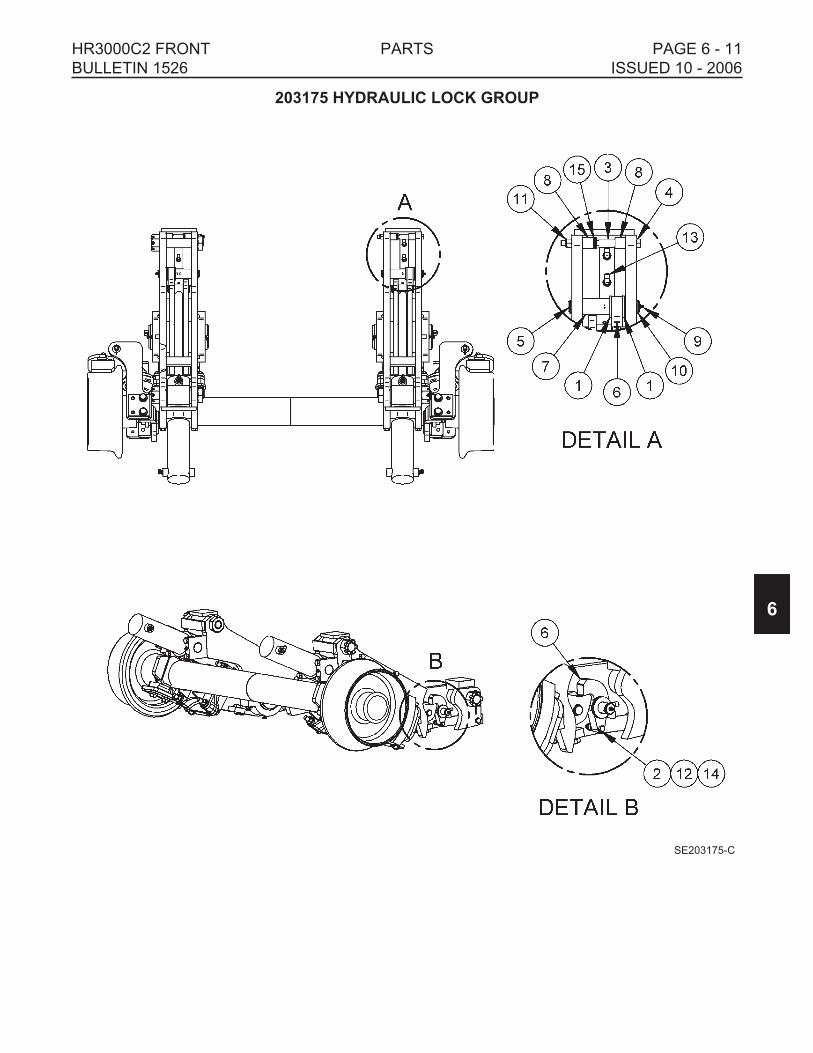
203175 HYDRAULIC LOCK GROUP
6
HR3000C2 FRONT PARTS PAGE 6 - 11
BULLETIN 1526 ISSUED 10 - 2006
SE203175-C

203193 RAIL SWEEP GROUP
ITEM PART NO DESCRIPTION QTY
203193 RAIL SWEEP GROUP . . . . . . . . . . . . . . . . . . . . . . . . . . . . . . . . . . . . . 1
1 203196 RAIL SWEEP ASSEMBLY, LEFT . . . . . . . . . . . . . . . . . . . . . . . . . . . . 1
1a 108509K1 Rail Sweep . . . . . . . . . . . . . . . . . . . . . . . . . . . . . . . . . . . . . . . . . . . 1
1b 108510 Rail Sweep Plate. . . . . . . . . . . . . . . . . . . . . . . . . . . . . . . . . . . . . . . 1
1c 203194 Rail Sweep Bracket, Left. . . . . . . . . . . . . . . . . . . . . . . . . . . . . . . . . 1
1d 202061 Hardened Washer, 3/8" . . . . . . . . . . . . . . . . . . . . . . . . . . . . . . . . . 2
1e F001125 Cap Screw, 3/8-16 x 1-1/4" GR 5 Hex Hd. . . . . . . . . . . . . . . . . . . . 2
1f F015922 Elastic Stop Nut, 3/8"-16. . . . . . . . . . . . . . . . . . . . . . . . . . . . . . . . . 2
2 203197 RAIL SWEEP ASSEMBLY, RIGHT . . . . . . . . . . . . . . . . . . . . . . . . . . . 1
2a 108509K1 Rail Sweep . . . . . . . . . . . . . . . . . . . . . . . . . . . . . . . . . . . . . . . . . . . 1
2b 108510 Rail Sweep Plate. . . . . . . . . . . . . . . . . . . . . . . . . . . . . . . . . . . . . . . 1
2c 203195 Rail Sweep Bracket, Right . . . . . . . . . . . . . . . . . . . . . . . . . . . . . . . 1
2d 202061 Hardened Washer, 3/8" . . . . . . . . . . . . . . . . . . . . . . . . . . . . . . . . . 2
2e F001125 Cap Screw, 3/8-16 x 1-1/4" GR 5 Hex Hd. . . . . . . . . . . . . . . . . . . . 2
2f F015922 Elastic Stop Nut, 3/8"-16. . . . . . . . . . . . . . . . . . . . . . . . . . . . . . . . . 2
3 F018650 Cap Screw, 1/2-13 x 1-1/2" GR 8 Hex Hd . . . . . . . . . . . . . . . . . . . . . . 4
4 202063 Hardened Washer, 1/2" . . . . . . . . . . . . . . . . . . . . . . . . . . . . . . . . . . . . 4
6
PAGE 6 - 12 PARTS HR3000C2 FRONT
ISSUED 10 - 2006 BULLETIN 1526
SE203193-C

NOTES
6
HR3000C2 FRONT PARTS PAGE 6 - 13
BULLETIN 1526 ISSUED 10 - 2006

162114 TRUCK BRAKE CONNECTION
ITEM PART NO DESCRIPTION QTY
162114 TRUCK BRAKE CONNECTION. . . . . . . . . . . . . . . . . . . . . . . . . . . . . . 1
1 F012055 90° Elbow, 9/16 M JIC x 3/8 M NPT . . . . . . . . . . . . . . . . . . . . . . . . 1
2 F018904 Hose, 5/16 x 48" Swivel 9/16 F JIC Both Ends . . . . . . . . . . . . . . . . 1
3 F012587 Grommet. . . . . . . . . . . . . . . . . . . . . . . . . . . . . . . . . . . . . . . . . . . . . 2
4 F010994 Adapter, 9/16 M JIC x 1/4 M NPT . . . . . . . . . . . . . . . . . . . . . . . . . . 1
5 F019332 Air Control Valve. . . . . . . . . . . . . . . . . . . . . . . . . . . . . . . . . . . . . . . 1
6 F010989 Pipe Plug, 1/4 M NPT . . . . . . . . . . . . . . . . . . . . . . . . . . . . . . . . . . . 1
7 120453 Bracket . . . . . . . . . . . . . . . . . . . . . . . . . . . . . . . . . . . . . . . . . . . . . . 1
8 F001113 Cap Screw, 5/16-18 x 1-1/4" Hex Hd . . . . . . . . . . . . . . . . . . . . . . . 2
9 F001100 SAE Lock Washer, 5/16" . . . . . . . . . . . . . . . . . . . . . . . . . . . . . . . . 2
10 F007021 Hex Nut, 5/16"-18 . . . . . . . . . . . . . . . . . . . . . . . . . . . . . . . . . . . . . . 2
11 122583 Instruction Plate, Rail Wheel… . . . . . . . . . . . . . . . . . . . . . . . . . . . . 1
12 F009591 Machine Screw, #10-24 x 3/4" Rd Hd . . . . . . . . . . . . . . . . . . . . . . . 2
13 F010988 90° Elbow, 9/16 M JIC x 1/4 M NPT . . . . . . . . . . . . . . . . . . . . . . . . 1
14 079235 Hose, 5/16 x 51" Swivel 9/16 F JIC Both Ends . . . . . . . . . . . . . . . . 1
15 F011152 Adapter, 9/16 M JIC x 9/16 M JIC. . . . . . . . . . . . . . . . . . . . . . . . . . 1
16 075540 Hose, 5/16 x 76" Swivel 9/16 F JIC Both Ends . . . . . . . . . . . . . . . . 1
17 120457 Decal, Rail Brake Operation… . . . . . . . . . . . . . . . . . . . . . . . . . . . . 1
6
PAGE 6 - 14 PARTS HR3000C2 FRONT
ISSUED 10 - 2006 BULLETIN 1526
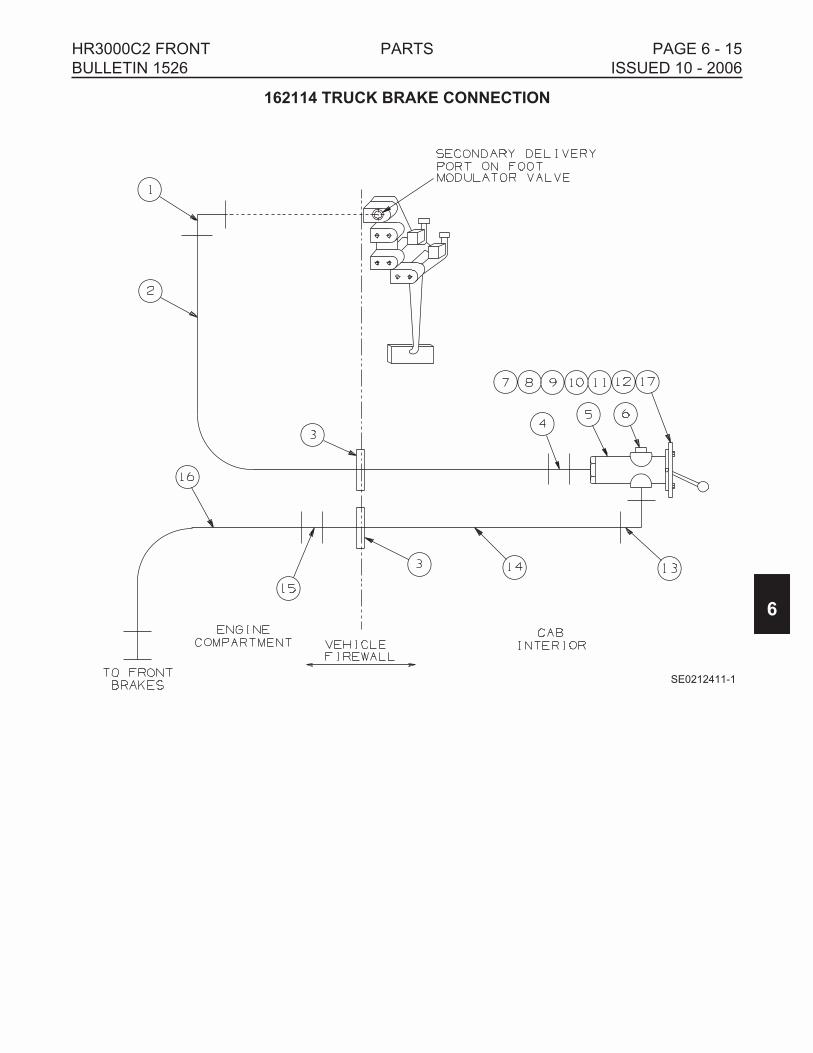
162114 TRUCK BRAKE CONNECTION
6
HR3000C2 FRONT PARTS PAGE 6 - 15
BULLETIN 1526 ISSUED 10 - 2006
SE0212411-1
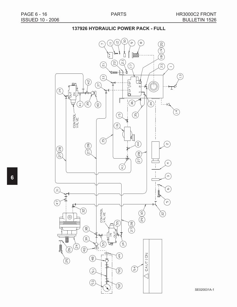
137926 HYDRAULIC POWER PACK - FULL
6
PAGE 6 - 16 PARTS HR3000C2 FRONT
ISSUED 10 - 2006 BULLETIN 1526
SE020031A-1

137926 HYDRAULIC POWER PACK - FULL
ITEM PART NO DESCRIPTION QTY
137926 HYDRAULIC POWER PACK -FULL . . . . . . . . . . . . . . . . . . . . . . . . . . 1
129136 HYDRAULIC RESERVOIR ASSEMBLY. . . . . . . . . . . . . . . . . . . . . 1
1 099444 Reservoir Only. . . . . . . . . . . . . . . . . . . . . . . . . . . . . . . . . . . . . . 1
2 F014155 Filter . . . . . . . . . . . . . . . . . . . . . . . . . . . . . . . . . . . . . . . . . . . . . 1
3 082205 Filter Flange . . . . . . . . . . . . . . . . . . . . . . . . . . . . . . . . . . . . . . . 1
4 077997 Flange Gasket . . . . . . . . . . . . . . . . . . . . . . . . . . . . . . . . . . . . . . 1
5 F001125 Cap Screw, 3/8-16 x 1-1/4" Hex Hd. . . . . . . . . . . . . . . . . . . . . . 4
6 F001025 SAE Lock Washer, 3/8" . . . . . . . . . . . . . . . . . . . . . . . . . . . . . . . 4
7 F022655 FILLER CAP . . . . . . . . . . . . . . . . . . . . . . . . . . . . . . . . . . . . . . . 1
8 F010465 Filler Screen . . . . . . . . . . . . . . . . . . . . . . . . . . . . . . . . . . . . . 1
9 056780 Filler Flange Gasket . . . . . . . . . . . . . . . . . . . . . . . . . . . . . . . 2
10 F010466 Filler Flange. . . . . . . . . . . . . . . . . . . . . . . . . . . . . . . . . . . . . . 1
11 F009723 Machine Screw, 10-24 x 3/8" Rd Hd . . . . . . . . . . . . . . . . . . . 6
12 F009541 SAE Lock Washer, #10 . . . . . . . . . . . . . . . . . . . . . . . . . . . . . 6
13 F010181 Drain Valve, 1/8 M NPT. . . . . . . . . . . . . . . . . . . . . . . . . . . . . . . 2
14 F012702 Pipe Plug, 3/8 M NPT Magnetic. . . . . . . . . . . . . . . . . . . . . . . . . 1
15 F001328 Pipe Nipple, 3/4 M NPT x 1-3/8" . . . . . . . . . . . . . . . . . . . . . . . . 1
16 F015452 FILTER - RETURN . . . . . . . . . . . . . . . . . . . . . . . . . . . . . . . . . . 1
16a F015453 Replacement Filter Element . . . . . . . . . . . . . . . . . . . . . . . . . 1
17 120993 VALVE, FLOW DIVIDER . . . . . . . . . . . . . . . . . . . . . . . . . . . . . . 1
17a F019415 Pressure Relief Washers (set of four) . . . . . . . . . . . . . . . . . . 1
18 F009663 Cap Screw, 5/16-18 x 2" Hex Hd. . . . . . . . . . . . . . . . . . . . . . . . 2
19 F007021 Hex Nut, 5/16"-18 . . . . . . . . . . . . . . . . . . . . . . . . . . . . . . . . . . . 2
20 F001100 SAE Lock Washer, 5/16" . . . . . . . . . . . . . . . . . . . . . . . . . . . . . . 2
21 F001125 Cap Screw, 3/8-16 x 1-1/4" Hex Hd . . . . . . . . . . . . . . . . . . . . . . . . 4
22 F001025 SAE Lock Washer, 3/8" . . . . . . . . . . . . . . . . . . . . . . . . . . . . . . . . . 4
23 F007020 Hex Nut, 3/8"-16 . . . . . . . . . . . . . . . . . . . . . . . . . . . . . . . . . . . . . . . 4
24 F023330 Hydraulic Pump . . . . . . . . . . . . . . . . . . . . . . . . . . . . . . . . . . . . . . . 1
25 F003136 Cap Screw, 1/2-13 x 1" Hex Hd . . . . . . . . . . . . . . . . . . . . . . . . . . . 2
26 F001075 SAE Lock Washer, 1/2" . . . . . . . . . . . . . . . . . . . . . . . . . . . . . . . . . 2
140344 HOSE GROUP . . . . . . . . . . . . . . . . . . . . . . . . . . . . . . . . . . . . . . . . 1
27 F009947 Hose, 13/32 x 960" (cut to length) . . . . . . . . . . . . . . . . . . . . . . . 1
28 F020713 Hose Fitting, Swivel 3/4 F JIC (install on hose F009947) . . . . . 8
29 F010298 Hose, 1-1/8 x 75" (cut to length) . . . . . . . . . . . . . . . . . . . . . . . . 1
30 F014307 Hose Fitting, Swivel 1-5/8 F JIC (install on hose F010298) . . . . 2
31 F013243 90° Elbow, 3/4 M NPT x 3/4 M JIC . . . . . . . . . . . . . . . . . . . . . . . . . 1
32 F021260 90° Elbow, 1 M NPT x 1-5/8 M JIC . . . . . . . . . . . . . . . . . . . . . . . . . 2
33 F012054 90° Elbow, 1/2 M NPT x 3/4 M JIC . . . . . . . . . . . . . . . . . . . . . . . . . 2
34 F011114 90° Elbow, 3/8 M NPT x 3/4 M JIC . . . . . . . . . . . . . . . . . . . . . . . . . 3
35 067736 Hose, 13/32 x 17" Swivel 3/4 F JIC Both Ends . . . . . . . . . . . . . . . . 2
36 F011170 Adapter, 3/8 M NPT x 3/4 M JIC . . . . . . . . . . . . . . . . . . . . . . . . . . . 1
37 F012704 90° Elbow, 3/4 M JIC x 3/8 M NPT . . . . . . . . . . . . . . . . . . . . . . . . . 1
6
HR3000C2 FRONT PARTS PAGE 6 - 17
BULLETIN 1526 ISSUED 10 - 2006

137926 HYDRAULIC POWER PACK - FULL
ITEM PART NO DESCRIPTION QTY
38 F013605 Tee, 3/4 M JIC x 3/8 M NPT x 3/8 M NPT. . . . . . . . . . . . . . . . . . . . 1
39 F015303K Nose Piece, 3/8 F NPT . . . . . . . . . . . . . . . . . . . . . . . . . . . . . . . . . 2
40 F015077 Dust Cap. . . . . . . . . . . . . . . . . . . . . . . . . . . . . . . . . . . . . . . . . . . . . 2
41 F014722 Tee, 3/8 F NPT x 3/4 M JIC x 3/8 M NPT . . . . . . . . . . . . . . . . . . . . 1
42 F011604 Adapter, 3/8 M NPT x 3/8 M NPT . . . . . . . . . . . . . . . . . . . . . . . . . . 1
43 F013629 Tee, 3/4 M JIC x 3/4 M JIC x 3/8 M NPT . . . . . . . . . . . . . . . . . . . . 1
44 F012024 Reducer Bushing, 3/4 M NPT x 3/8 F NPT . . . . . . . . . . . . . . . . . . . 1
45 Not Used
47 F011617 Reducer Bushing, 1 M NPT x 3/4 F NPT . . . . . . . . . . . . . . . . . . . . 1
099137K PRESSURE GAUGE ASSEMBLY. . . . . . . . . . . . . . . . . . . . . . . . . 1
48 F015110K Body, 3/8 F NPT. . . . . . . . . . . . . . . . . . . . . . . . . . . . . . . . . . . . 1
49 F015111 Dust Cap . . . . . . . . . . . . . . . . . . . . . . . . . . . . . . . . . . . . . . . . . . 1
50 F012056 Adapter, 3/8 M NPT x 9/16 M JIC . . . . . . . . . . . . . . . . . . . . . . . 1
51 171878 Hose, 3/8 x 14" Swivel 9/16 F JIC Both Ends . . . . . . . . . . . . . . 1
52 F011109 Adapter, 9/16 M JIC x 1/4 F NPT . . . . . . . . . . . . . . . . . . . . . . . 1
53 F011432K Pressure Gauge, 1/4 M NPT . . . . . . . . . . . . . . . . . . . . . . . . . . . 1
54 137941 Decal, Caution -Recommended… . . . . . . . . . . . . . . . . . . . . . . . . . 1
55 F015103 Adapter, 3/8 F NPT x 3/4 M STR . . . . . . . . . . . . . . . . . . . . . . . . . . 2
6
PAGE 6 - 18 PARTS HR3000C2 FRONT
ISSUED 10 - 2006 BULLETIN 1526

NOTES
6
HR3000C2 FRONT PARTS PAGE 6 - 19
BULLETIN 1526 ISSUED 10 - 2006

137927 HYDRAULIC POWER PACK - ABBREVIATED
6
PAGE 6 - 20 PARTS HR3000C2 FRONT
ISSUED 10 - 2006 BULLETIN 1526
SE137927A-1

137927 HYDRAULIC POWER PACK - ABBREVIATED
ITEM PART NO DESCRIPTION QTY
137927 HYDRAULIC POWER PACK -ABBREVIATED . . . . . . . . . . . . . . . . . . 1
1 F016490 Selector Valve. . . . . . . . . . . . . . . . . . . . . . . . . . . . . . . . . . . . . . . . . 1
2 F002760 Cap Screw, 3/8-16 x 2-1/4" Hex Hd . . . . . . . . . . . . . . . . . . . . . . . . 2
3 F001025 SAE Lock Washer, 3/8" . . . . . . . . . . . . . . . . . . . . . . . . . . . . . . . . . 2
4 F009670 Hex Grip Nut, 3/8"-16. . . . . . . . . . . . . . . . . . . . . . . . . . . . . . . . . . . 2
5 120993 VALVE, FLOW DIVIDER . . . . . . . . . . . . . . . . . . . . . . . . . . . . . . . . 1
F019415 Pressure Relief Washers (set of four) . . . . . . . . . . . . . . . . . . . . 1
6 F009663 Cap Screw, 5/16-18 x 2" Hex Hd . . . . . . . . . . . . . . . . . . . . . . . . . . 2
7 F001100 SAE Lock Washer, 5/16" . . . . . . . . . . . . . . . . . . . . . . . . . . . . . . . . 2
8 F007021 Hex Nut, 5/16"-18 . . . . . . . . . . . . . . . . . . . . . . . . . . . . . . . . . . . . . . 2
9 F012010 90° Elbow Street, 3/4 F NPT x 3/4 M NPT . . . . . . . . . . . . . . . . . . . 1
10 F010584 90° Elbow, 1-1/16 M JIC x 1/2 M NPT . . . . . . . . . . . . . . . . . . . . . . 1
11 F011114 90° Elbow, 3/4 M JIC x 3/8 M NPT . . . . . . . . . . . . . . . . . . . . . . . . . 2
12 F010586 90° Elbow, 1-1/16 M JIC x 3/4 M NPT . . . . . . . . . . . . . . . . . . . . . . 1
13 F010581 Adapter, 1-1/16 M JIC x 3/4 M NPT . . . . . . . . . . . . . . . . . . . . . . . . 2
14 F011170 Adapter, 3/4 M JIC x 3/8 M NPT . . . . . . . . . . . . . . . . . . . . . . . . . . . 2
15 F013210 Adapter, 1-1/16 M JIC x 1/2 M NPT . . . . . . . . . . . . . . . . . . . . . . . . 2
16 F012027 Adapter, 3/4 M JIC x 1/2 M NPT . . . . . . . . . . . . . . . . . . . . . . . . . . . 2
17 F013605 Tee, 3/4 M JIC x 3/8 M NPT x 3/8 M NPT. . . . . . . . . . . . . . . . . . . . 1
18 F014722 Tee, 3/8 F NPT x 3/4 M JIC x 3/8 M NPT . . . . . . . . . . . . . . . . . . . . 1
19 F010692 Tee, 1/2 F NPT x 1/2 M NPT x 1/2 F NPT . . . . . . . . . . . . . . . . . . . 2
20 F015303K Nose Piece, 3/8 F NPT . . . . . . . . . . . . . . . . . . . . . . . . . . . . . . . . . 2
21 F015077 Dust Cap. . . . . . . . . . . . . . . . . . . . . . . . . . . . . . . . . . . . . . . . . . . . . 2
22 F011604 Adapter, 3/8 M NPT x 3/8 M NPT . . . . . . . . . . . . . . . . . . . . . . . . . . 1
23 071692 Hose, 5/16 x 48" Swivel 1-1/16 F JIC Both Ends . . . . . . . . . . . . . . 2
24 111100 Hose, 3/4 x 28" Swivel 1-1/16 F JIC Both Ends . . . . . . . . . . . . . . . 1
25 071867 Hose, 1/2 x 19-3/4" Swivel 3/4 F JIC Both Ends . . . . . . . . . . . . . . . 1
140345 HOSE GROUP . . . . . . . . . . . . . . . . . . . . . . . . . . . . . . . . . . . . . . . . 1
26 F009947 Hose, 13/32 x 960" (cut to length) . . . . . . . . . . . . . . . . . . . . . . . 1
27 F020713 Hose Fitting, Swivel 3/4 F JIC (install on hose F009947) . . . . . 6
099137K PRESSURE GAUGE ASSEMBLY. . . . . . . . . . . . . . . . . . . . . . . . . 1
29 F015110K Body, 3/8 F NPT. . . . . . . . . . . . . . . . . . . . . . . . . . . . . . . . . . . . 1
30 F015111 Dust Cap . . . . . . . . . . . . . . . . . . . . . . . . . . . . . . . . . . . . . . . . . . 1
31 F012056 Adapter, 3/8 M NPT x 9/16 M JIC . . . . . . . . . . . . . . . . . . . . . . . 1
32 171878 Hose, 3/8 x 14" Swivel 9/16 F JIC Both Ends . . . . . . . . . . . . . . 1
33 F011109 Adapter, 9/16 M JIC x 1/4 F NPT . . . . . . . . . . . . . . . . . . . . . . . 1
34 F011432K Pressure Gauge, 1/4 M NPT . . . . . . . . . . . . . . . . . . . . . . . . . . . 1
35 F015103 Adapter, 3/8 F NPT x 3/4 M STR . . . . . . . . . . . . . . . . . . . . . . . . . . 2
6
HR3000C2 FRONT PARTS PAGE 6 - 21
BULLETIN 1526 ISSUED 10 - 2006

159510 WHEEL LOAD JACK GROUP
ITEM PART NO DESCRIPTION QTY
159510 WHEEL LOAD JACK GROUP . . . . . . . . . . . . . . . . . . . . . . . . . . . . . . 1
1 F025272 Hydraulic Jack . . . . . . . . . . . . . . . . . . . . . . . . . . . . . . . . . . . . . . . . 1
2 159512 Gauge Assembly with Decals . . . . . . . . . . . . . . . . . . . . . . . . . . . . . 1
3 146353 90° Elbow, 1/4 F NPT x 1/4 M NPT . . . . . . . . . . . . . . . . . . . . . . . . 1
4 F023088 Adapter, 1/4 F NPT x 1/4 M NPT . . . . . . . . . . . . . . . . . . . . . . . . . . 1
6
PAGE 6 - 22 PARTS HR3000C2 FRONT
ISSUED 10 - 2006 BULLETIN 1526
2
3
4
1
SE021048

164574 SIGHT ROD EXTENSION GROUP
PART NO DESCRIPTION QTY
164574 SIGHT ROD EXTENSION GROUP . . . . . . . . . . . . . . . . . . . . . . . . . . . 1
130195 Sight Rod Kit (includes two sight rods) . . . . . . . . . . . . . . . . . . . . . . 1
135809 Sight Rod Extension . . . . . . . . . . . . . . . . . . . . . . . . . . . . . . . . . . . . 2
161855 Mounting Bar . . . . . . . . . . . . . . . . . . . . . . . . . . . . . . . . . . . . . . . . . 2
F022036 Cap Screw, 1/2-13 x 1-1/4" Hex Flg Hd . . . . . . . . . . . . . . . . . . . . . 2
F022037 Hex Flg Nut, 1/2"-13 . . . . . . . . . . . . . . . . . . . . . . . . . . . . . . . . . . . . 2
203157 DECAL SERVICE GROUP
PART NO DESCRIPTION QTY
203157 DECAL SERVICE GROUP . . . . . . . . . . . . . . . . . . . . . . . . . . . . . . . . . 1
F018082 Decal, Safety Instructions: Lock Front Wheels… . . . . . . . . . . . . . . 1
140220 Decal, Warning: Do Not Operate…. . . . . . . . . . . . . . . . . . . . . . . . . 2
155007 Decal, HY-RAIL® Vehicle Completed By… . . . . . . . . . . . . . . . . . . 1
191761 Decal, Harsco Track Technologies . . . . . . . . . . . . . . . . . . . . . . . . . 2
201564 Decal, Control Valve Operating Instructions . . . . . . . . . . . . . . . . . . 1
201565 Decal, Operating Instructions . . . . . . . . . . . . . . . . . . . . . . . . . . . . . 1
201567 Decal, Operating Instructions . . . . . . . . . . . . . . . . . . . . . . . . . . . . . 1
3410748 Decal, Operating Instructions . . . . . . . . . . . . . . . . . . . . . . . . . . . . . 1
6
HR3000C2 FRONT PARTS PAGE 6 - 23
BULLETIN 1526 ISSUED 10 - 2006
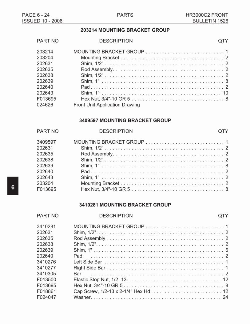
203214 MOUNTING BRACKET GROUP
PART NO DESCRIPTION QTY
203214 MOUNTING BRACKET GROUP . . . . . . . . . . . . . . . . . . . . . . . . . . . . . 1
203204 Mounting Bracket . . . . . . . . . . . . . . . . . . . . . . . . . . . . . . . . . . . . . . 2
202631 Shim, 1/2" . . . . . . . . . . . . . . . . . . . . . . . . . . . . . . . . . . . . . . . . . . . . 2
202635 Rod Assembly. . . . . . . . . . . . . . . . . . . . . . . . . . . . . . . . . . . . . . . . . 2
202638 Shim, 1/2" . . . . . . . . . . . . . . . . . . . . . . . . . . . . . . . . . . . . . . . . . . . . 2
202639 Shim, 1" . . . . . . . . . . . . . . . . . . . . . . . . . . . . . . . . . . . . . . . . . . . . . 8
202640 Pad . . . . . . . . . . . . . . . . . . . . . . . . . . . . . . . . . . . . . . . . . . . . . . . . . 2
202643 Shim, 1" . . . . . . . . . . . . . . . . . . . . . . . . . . . . . . . . . . . . . . . . . . . . 10
F013695 Hex Nut, 3/4"-10 GR 5 . . . . . . . . . . . . . . . . . . . . . . . . . . . . . . . . . . 8
024626 Front Unit Application Drawing
3409597 MOUNTING BRACKET GROUP
PART NO DESCRIPTION QTY
3409597 MOUNTING BRACKET GROUP . . . . . . . . . . . . . . . . . . . . . . . . . . . . . 1
202631 Shim, 1/2" . . . . . . . . . . . . . . . . . . . . . . . . . . . . . . . . . . . . . . . . . . . . 2
202635 Rod Assembly. . . . . . . . . . . . . . . . . . . . . . . . . . . . . . . . . . . . . . . . . 2
202638 Shim, 1/2" . . . . . . . . . . . . . . . . . . . . . . . . . . . . . . . . . . . . . . . . . . . . 2
202639 Shim, 1" . . . . . . . . . . . . . . . . . . . . . . . . . . . . . . . . . . . . . . . . . . . . . 8
202640 Pad . . . . . . . . . . . . . . . . . . . . . . . . . . . . . . . . . . . . . . . . . . . . . . . . . 2
202643 Shim, 1" . . . . . . . . . . . . . . . . . . . . . . . . . . . . . . . . . . . . . . . . . . . . . 2
203204 Mounting Bracket . . . . . . . . . . . . . . . . . . . . . . . . . . . . . . . . . . . . . . 2
F013695 Hex Nut, 3/4"-10 GR 5 . . . . . . . . . . . . . . . . . . . . . . . . . . . . . . . . . . 8
3410281 MOUNTING BRACKET GROUP
PART NO DESCRIPTION QTY
3410281 MOUNTING BRACKET GROUP . . . . . . . . . . . . . . . . . . . . . . . . . . . . . 1
202631 Shim, 1/2". . . . . . . . . . . . . . . . . . . . . . . . . . . . . . . . . . . . . . . . . . . . . . . 2
202635 Rod Assembly . . . . . . . . . . . . . . . . . . . . . . . . . . . . . . . . . . . . . . . . . . . 2
202638 Shim, 1/2". . . . . . . . . . . . . . . . . . . . . . . . . . . . . . . . . . . . . . . . . . . . . . . 2
202639 Shim, 1" . . . . . . . . . . . . . . . . . . . . . . . . . . . . . . . . . . . . . . . . . . . . . . . . 6
202640 Pad . . . . . . . . . . . . . . . . . . . . . . . . . . . . . . . . . . . . . . . . . . . . . . . . . 2
3410276 Left Side Bar . . . . . . . . . . . . . . . . . . . . . . . . . . . . . . . . . . . . . . . . . . . . 1
3410277 Right Side Bar . . . . . . . . . . . . . . . . . . . . . . . . . . . . . . . . . . . . . . . . . . . 1
3410305 Bar . . . . . . . . . . . . . . . . . . . . . . . . . . . . . . . . . . . . . . . . . . . . . . . . . 2
F013500 Elastic Stop Nut, 1/2 -13. . . . . . . . . . . . . . . . . . . . . . . . . . . . . . . . . . . 12
F013695 Hex Nut, 3/4"-10 GR 5 . . . . . . . . . . . . . . . . . . . . . . . . . . . . . . . . . . . . . 8
F018861 Cap Screw, 1/2-13 x 2-1/4" Hex Hd . . . . . . . . . . . . . . . . . . . . . . . . . . 12
F024047 Washer. . . . . . . . . . . . . . . . . . . . . . . . . . . . . . . . . . . . . . . . . . . . . . . . 24
6
PAGE 6 - 24 PARTS HR3000C2 FRONT
ISSUED 10 - 2006 BULLETIN 1526

SECTION 7 - VEHICLE APPLICATIONS
TABLE OF CONTENTS
2004 FREIGHTLINER . . . . . . . . . . . . . . . . . . . . . . . . . . . . . . . . . . . . . . . . . . . . . . . 7 - 2
2006 INTERNATIONAL . . . . . . . . . . . . . . . . . . . . . . . . . . . . . . . . . . . . . . . . . . . . . . 7 - 2
2007 INTERNATIONAL . . . . . . . . . . . . . . . . . . . . . . . . . . . . . . . . . . . . . . . . . . . . . . 7 - 3
7
HR3000C2 FRONT VEHICLE APPLICATIONS PAGE 7 - 1
BULLETIN 1526 ISSUED 10 - 2006

2004 FREIGHTLINER 2006 INTERNATIONAL
M-2 106V 4300 SERIES
12,000 GAWR - FRONT 12,000 GAWR - FRONT
HR3000C2 FRONT HR3000C2 FRONT
HR3000B1 REAR HR3000B1 REAR
REQUIRED GROUPS
Guide Wheel Unit Application . . . . . . . . . . . . . . 203259 . . . . . . . . . . . . . . . 203259
Front Guide Wheel Unit . . . . . . . . . . . . . . . . . . . 202600 . . . . . . . . . . . . . . . 202600
Mounting Brackets . . . . . . . . . . . . . . . . . . . . . . . 203214 . . . . . . . . . . . . . . . 3409597
Lock Group (one required)
Manual Lock . . . . . . . . . . . . . . . . . . . . . . . . . 203174 . . . . . . . . . . . . . . . 203174
Application Drawing. . . . . . . . . . . . . . . . . . 024607 . . . . . . . . . . . . . . . 024607
Hydraulic Lock. . . . . . . . . . . . . . . . . . . . . . . . 203175 . . . . . . . . . . . . . . . 203175
Application Drawing. . . . . . . . . . . . . . . . . . 024608 . . . . . . . . . . . . . . . 024608
Steering Lock. . . . . . . . . . . . . . . . . . . . . . . . . . . 202549 . . . . . . . . . . . . . . . 201711
Application Drawing - Front . . . . . . . . . . . . . . . . 024626 . . . . . . . . . . . . . . . ––––––
ACCESSORY GROUP OPTIONS
Hydraulic Power Pack - Full. . . . . . . . . . . . . . . . 137926 . . . . . . . . . . . . . . . 137926
Hydraulic Power Pack - Abbreviated . . . . . . . . . 137927 . . . . . . . . . . . . . . . 137927
Truck Brake Connection . . . . . . . . . . . . . . . . . . 162114 . . . . . . . . . . . . . . . 162114
* Rail Sweeps - Front . . . . . . . . . . . . . . . . . . . . . . 203193 . . . . . . . . . . . . . . . 203193
Wheel Load Jack . . . . . . . . . . . . . . . . . . . . . . . . 159510 . . . . . . . . . . . . . . . 159510
Sight Rod Kit And Extension . . . . . . . . . . . . . . . 164574 . . . . . . . . . . . . . . . 164574
* Recommended Safety Option
7
PAGE 7 - 2 VEHICLE APPLICATIONS HR3000C2 FRONT
ISSUED 10 - 2006 BULLETIN 1526

2007 INTERNATIONAL 2007 INTERNATIONAL
4200 SERIES 3300 CE SERIES
12,000 GAWR - FRONT 12,000 GAWR - FRONT
HR3000C2 FRONT HR3000C2 FRONT
HR3000A1 REAR HR3000A1 REAR
REQUIRED GROUPS
Guide Wheel Unit Application . . . . . . . . . . . . . . 3410311 . . . . . . . . . . . . . . 3410311
Front Guide Wheel Unit . . . . . . . . . . . . . . . . . . . 202600 . . . . . . . . . . . . . . . 202600
Mounting Brackets . . . . . . . . . . . . . . . . . . . . . . . 3410281 . . . . . . . . . . . . . . 3410281
Lock Group (one required)
Manual Lock . . . . . . . . . . . . . . . . . . . . . . . . . 203174 . . . . . . . . . . . . . . . 203174
Application Drawing. . . . . . . . . . . . . . . . . . 024607 . . . . . . . . . . . . . . . 024607
Hydraulic Lock. . . . . . . . . . . . . . . . . . . . . . . . 203175 . . . . . . . . . . . . . . . 203175
Application Drawing. . . . . . . . . . . . . . . . . . 024608 . . . . . . . . . . . . . . . 024608
Steering Lock. . . . . . . . . . . . . . . . . . . . . . . . . . . 201711 . . . . . . . . . . . . . . . 201711
ACCESSORY GROUP OPTIONS
Hydraulic Power Pack - Full. . . . . . . . . . . . . . . . 137926 . . . . . . . . . . . . . . . 137926
Hydraulic Power Pack - Abbreviated . . . . . . . . . 137927 . . . . . . . . . . . . . . . 137927
Truck Brake Connection . . . . . . . . . . . . . . . . . . 162114 . . . . . . . . . . . . . . . 162114
* Rail Sweeps - Front . . . . . . . . . . . . . . . . . . . . . . 203193 . . . . . . . . . . . . . . . 203193
Wheel Load Jack . . . . . . . . . . . . . . . . . . . . . . . . 159510 . . . . . . . . . . . . . . . 159510
Sight Rod Kit And Extension . . . . . . . . . . . . . . . 164574 . . . . . . . . . . . . . . . 164574
* Recommended Safety Option
7
HR3000C2 FRONT VEHICLE APPLICATIONS PAGE 7 - 3
BULLETIN 1526 ISSUED 10 - 2006

NOTES
7
PAGE 7 - 4 VEHICLE APPLICATIONS HR3000C2 FRONT
ISSUED 10 - 2006 BULLETIN 1526

APPENDIX A - CONVERSION TABLES
TABLE OF CONTENTS
BOLT TORQUE REQUIREMENTS - STANDARD TYPE FASTENERS. . . . . . . . . . . . A - 2
BOLT TORQUE REQUIREMENTS - SERRATED TYPE FLANGE FASTENERS . . . . A - 3
BOLT TORQUE REQUIREMENTS - METRIC TYPE FASTENERS. . . . . . . . . . . . . . . A - 4
INCH TO MILLIMETERS . . . . . . . . . . . . . . . . . . . . . . . . . . . . . . . . . . . . . . . . . . . . . . . A - 6
FEET TO METERS. . . . . . . . . . . . . . . . . . . . . . . . . . . . . . . . . . . . . . . . . . . . . . . . . . . . A - 6
POUNDS TO KILOGRAMS . . . . . . . . . . . . . . . . . . . . . . . . . . . . . . . . . . . . . . . . . . . . . A - 7
POUNDS PER SQUARE INCH TO BAR . . . . . . . . . . . . . . . . . . . . . . . . . . . . . . . . . . . A - 7
POUNDS PER SQUARE INCH TO KILOPASCALS. . . . . . . . . . . . . . . . . . . . . . . . . . . A - 7
FAHRENHEIT TO CELSIUS (Centigrade) . . . . . . . . . . . . . . . . . . . . . . . . . . . . . . . . . . A - 8
MILES PER HOUR TO KILOMETERS PER HOUR . . . . . . . . . . . . . . . . . . . . . . . . . . . A - 9
GALLONS TO LITERS . . . . . . . . . . . . . . . . . . . . . . . . . . . . . . . . . . . . . . . . . . . . . . . . . A - 9
A
HR3000C2 FRONT APPENDIX A PAGE A - 1
BULLETIN 1526 ISSUED 10 - 2006

Appendix A
FIGURE A-1
STANDARD BOLT TORQUE REQUIREMENTS TABLE
STANDARD TYPE FASTENERS
The torque values listed below are for standard-type fasteners only. The torque values listed are based on wet and
(lubricated) dry conditions. The torque values for 1/4 and 5/16 inch size fasteners are listed in lb-in and N-m torque
equivalents. The torque values for all other size fasteners are listed lb-ft and N-m torque equivalents. Use lower grade
torque values if bolt and nut have different SAE grades. Manufacturer’s SAE grade markings may vary.
STANDARD MARKINGS AND TORQUE SPECIFICATIONS
SAE Grade 1 or 2 5 8
FastenerStandard
SAE GradeMarkings
FastenerBody Size
Inch-Thread
Torque Torque Torque
Wet Dry Wet Dry Wet Dry
lb-in N-m lb-in N-m lb-in N-m lb-in N-m lb-in N-m lb-in N-m
1/4 - 20 49 5.5 65 7.3 75 8.5 100 11.3 107 12.0 142 16.0
1/4 - 28 56 6.5 74 8.3 86 9.7 114 12.8 122 13.8 162 18.3
5/16 - 18 103 11.6 137 15.5 157 17.7 208 23.5 220 24.8 293 33.1
5/16 - 24 113 12.7 150 16.9 173 19.5 230 25.9 244 27.5 325 36.7
FastenerBody Size
Inch-Thread
Torque Torque Torque
Wet Dry Wet Dry Wet Dry
lb-ft N-m lb-ft N-m lb-ft N-m lb-ft N-m lb-ft N-m lb-ft N-m
3/8 - 16 15 20 20 27 23 31 31 42 32 43 43 58
3/8 - 24 17 23 23 31 26 35 35 47 37 50 49 66
7/16 - 14 24 32 32 43 37 50 49 66 52 70 69 93
7/16 - 20 27 36 36 49 42 57 56 76 58 78 77 104
1/2 - 13 39 53 52 70 57 77 76 103 80 108 106 144
1/2 - 20 41 55 55 74 64 87 85 115 90 122 120 163
9/16 - 12 53 72 71 96 82 111 109 148 115 156 153 207
9/16 - 18 59 80 78 106 91 123 121 164 129 175 172 233
5/8 - 11 73 99 97 131 113 155 150 203 160 217 213 289
5/8 - 18 83 112 110 149 128 173 170 230 180 244 239 324
3/4 - 10 129 175 172 233 200 271 266 361 282 382 375 508
3/4 - 16 144 195 192 260 223 302 297 403 315 427 419 568
7/8 - 9 124 168 165 224 323 438 430 583 454 615 604 819
7/8 - 14 138 187 184 249 355 481 472 640 501 679 666 903
1 - 8 188 255 250 339 483 655 642 870 681 923 906 1228
1 - 14 210 285 279 378 541 733 720 976 764 1036 1016 1377
1-1/8 - 7 266 361 354 480 596 808 793 1075 966 1310 1285 1742
1-1/8 - 12 297 403 395 535 668 906 888 1204 1083 1468 1440 1952
1-1/4 - 7 375 508 499 676 841 1140 1119 1517 1363 1848 1813 2458
1-1/4 - 12 415 563 552 748 930 1261 1237 1677 1509 2046 2007 2721
1-3/8 - 6 492 667 654 887 1102 1494 1466 1988 1787 2423 2377 3223
1-3/8 - 12 560 759 745 1010 1255 1701 1670 2264 2034 2758 2705 3667
1-1/2 - 6 653 885 868 1177 1463 1983 1946 2638 2371 3215 3153 4275
1-1/2 - 12 734 995 976 1323 1645 2230 2188 2966 2668 3617 3548 4810
A
PAGE A - 2 APPENDIX A HR3000C2 FRONT
ISSUED 10 - 2006 BULLETIN 1526

Appendix A
FIGURE A-2
STANDARD BOLT TORQUE REQUIREMENTS TABLE
SERRATED TYPE FLANGE FASTENERS
The torque values listed below are for serrated-type flange fasteners only. The torque values listed are based on wet
(lubricated) and dry conditions. The torque values for all other size fasteners are listed in lb-ft and N-m torque
equivalents. Use lower grade torque values if bolt and nut have different SAE grades. Manufacturer’s SAE grade
markings may vary.
STANDARD MARKINGS AND TORQUE SPECIFICATIONS
SAE Grade 1 or 2 5
FastenerStandard
SAE GradeMarkings
FastenerBody Size
Inch-Thread
Torque Torque
Wet Dry Wet Dry
lb-ft N-m lb-ft N-m lb-ft N-m lb-ft N-m
1/4 - 20 8 10.8 11 14.9 11 14.9 15 20.3
1/4 - 28 9 12.2 12 16.3 12 16.3 16 21.7
5/16 - 18 13 17.6 17 23.0 20 27.1 27 36.6
5/16 - 24 13 17.6 17 23.0 32 43.3 43 58.3
3/8 - 16 23 31 31 42 40 54 53 72
3/8 - 24 25 34 33 45 43 58 57 77
7/16 - 14 38 51 51 69 55 74 73 99
7/16 - 20 40 54 53 72 60 81 80 108
1/2 - 13 60 81 80 108 95 129 127 172
1/2 - 20 65 88 87 118 100 135 133 180
9/16 - 12 78 106 104 141 140 190 187 253
9/16 - 18 85 115 113 153 150 203 200 271
5/8 - 11 125 169 167 226 190 258 253 343
5/8 - 18 135 183 180 244 220 298 293 397
3/4 - 10 225 305 300 407 350 474 467 633
3/4 - 16 250 339 333 451 400 542 533 723
7/8 - 9 350 474 467 633 550 746 733 994
7/8 - 14 375 508 500 678 600 813 800 1085
1 - 8 480 651 640 868 750 1017 1000 1356
1 - 14 500 678 666 903 800 1085 1066 1445A
HR3000C2 FRONT APPENDIX A PAGE A - 3
BULLETIN 1526 ISSUED 10 - 2006

Appendix A
FIGURE A-3
BOLT TORQUE REQUIREMENTS TABLE
METRIC TYPE FASTENERS
Do not use these values if a different torque value or tightening procedure is given for a specific application. Torque
values listed are for general use only. Check tightness of fasteners periodically. Fasteners should be replaced with the
same or higher property class. If higher property class fasteners are used, these should only be tightened to the
strength of the original. Make sure fastener's threads are clean and that thread engagement is properly started. This
will help prevent them from failing when tightening.
*Lubricated means coated with a lubricant such as engine oil, or fasteners with phosphate and oil coatings. Dry means
plain or zinc plated without any lubrication.
PropertyClass and
HeadMarkings
PropertyClass and
HeadMarkings
Size
Class 4.8 Class 8.8 or 9.8
* Lubricated * Dry * Lubricated * Dry
N - m lb - ft N - m lb - ft N - m lb - ft N - m lb - ft
M 6 4.8 3.5 6 4.5 9 6.5 11 8.5
M 8 12 8.5 15 11 22 16 28 20
M10 23 17 29 21 43 32 55 40
M12 40 29 50 37 75 55 95 70
M14 63 47 80 60 120 88 150 110
M16 100 73 125 92 190 140 240 175
M18 135 100 175 125 260 195 330 250
M20 190 140 240 180 375 275 475 350
M22 260 190 330 250 510 375 650 475
M24 330 250 425 310 650 475 825 600
M27 490 360 625 450 950 700 1200 875
M30 675 490 850 625 1300 950 1650 1200
M33 900 675 1150 850 1750 1300 2200 1650
M36 1150 850 1450 1075 2250 1650 2850 2100
A
PAGE A - 4 APPENDIX A HR3000C2 FRONT
ISSUED 10 - 2006 BULLETIN 1526
4.8
5
8.8 9.8
10

Appendix A
FIGURE A-4
BOLT TORQUE REQUIREMENTS TABLE
METRIC TYPE FASTENERS
Do not use these values if a different torque value or tightening procedure is given for a specific application. Torque
values listed are for general use only. Check tightness of fasteners periodically. Fasteners should be replaced with the
same or higher property class. If higher property class fasteners are used, these should only be tightened to the
strength of the original. Make sure fastener's threads are clean and that thread engagement is properly started. This
will help prevent them from failing when tightening.
*Lubricated means coated with a lubricant such as engine oil, or fasteners with phosphate and oil coatings. Dry means
plain or zinc plated without any lubrication.
PropertyClass and
HeadMarkings
PropertyClass and
HeadMarkings
Size
Class 10.9 Class 12.9
* Lubricated * Dry * Lubricated * Dry
N - m lb - ft N - m lb - ft N - m lb - ft N - m lb - ft
M 6 13 9.5 17 12 15 11.5 19 14.5
M 8 32 24 40 30 37 28 47 35
M10 63 47 80 60 75 55 95 70
M12 110 80 140 105 130 95 165 120
M14 175 130 225 165 205 150 260 190
M16 275 200 350 255 320 240 400 300
M18 375 275 475 350 440 325 560 410
M20 530 400 675 500 625 460 800 580
M22 725 540 925 675 850 625 1075 800
M24 925 675 1150 850 1075 800 1350 1000
M27 1350 1000 1700 1250 1600 1150 2000 1500
M30 1850 1350 2300 1700 2150 1600 2700 2000
M33 2500 1850 3150 2350 2900 2150 3700 2750
M36 3200 2350 4050 3000 3750 2750 4750 3500
A
HR3000C2 FRONT APPENDIX A PAGE A - 5
BULLETIN 1526 ISSUED 10 - 2006
10.9
10
12.9
12

Appendix A
FIGURE A-5
INCH TO MILLIMETER CONVERSION TABLE
1 INCH = 25.4 MILLIMETERS
FRACTIONS DECIMALS MILLIMETERS FRACTIONS DECIMALS MILLIMETERS
1/64 .016 0.397 33/64 .516 13.097
1/32 .031 0.794 17/32 .531 13.494
3/64 .047 1.191 35/64 .547 13.891
1/16 .063 1.588 9/16 .563 14.288
5/64 .078 1.984 37/64 .578 14.684
3/32 .094 2.381 19/32 .594 15.081
7/64 .109 2.778 39/64 .609 15.478
1/8 .125 3.175 5/8 .625 15.875
9/64 .141 3.572 41/64 .641 16.272
5/32 .156 3.969 21/32 .656 16.669
11/64 .172 4.366 43/64 .672 17.066
3/16 .188 4.763 11/16 .688 17.463
13/64 .203 5.159 45/64 .703 17.859
7/32 .219 5.556 23/32 .719 18.256
15/64 .234 5.953 47/64 .734 18.653
1/4 .250 6.350 3/4 .750 19.050
17/64 .266 6.747 49/64 .766 19.447
9/32 .281 7.144 25/32 .781 19.844
19/64 .297 7.541 51/64 .797 20.241
5/16 .313 7.938 13/16 .813 20.638
21/64 .328 8.334 53/64 .828 21.034
11/32 .344 8.731 27/32 .844 21.431
23/64 .359 9.128 55/64 .859 21.828
3/8 .375 9.525 7/8 .875 22.225
25/64 .391 9.922 57/64 .891 22.622
13/32 .406 10.319 29/32 .906 23.019
27/64 .422 10.716 59/64 .922 23.416
7/16 .438 11.113 15/16 .938 23.813
29/64 .453 11.509 61/64 .953 24.209
15/32 .469 11.906 31/32 .969 24.606
31/64 .484 12.303 63/64 .984 25.003
1/2 .500 12.700 1 1.000 25.400
FIGURE A-6
FEET TO METERS CONVERSION TABLE
1 FOOT = 0.3048 METER
FEET METERS FEET METERS FEET METERS FEET METERS FEET METERS
100 30.480 10 3.048 1 0.305 0.1 0.030 0.01 0.003
200 60.960 20 6.096 2 0.610 0.2 0.061 0.02 0.006
300 91.440 30 9.144 3 0.914 0.3 0.091 0.03 0.009
400 121.920 40 12.192 4 1.219 0.4 0.122 0.04 0.012
500 152.400 50 15.240 5 1.524 0.5 0.152 0.05 0.015
600 182.880 60 18.288 6 1.829 0.6 0.183 0.06 0.018
700 213.360 70 21.336 7 2.134 0.7 0.213 0.07 0.021
800 243.840 80 24.384 8 2.438 0.8 0.244 0.08 0.024
900 274.320 90 27.432 9 2.743 0.9 0.274 0.09 0.027
1,000 304.800 100 30.480 10 3.048 1.0 0.305 0.10 0.030
A
PAGE A - 6 APPENDIX A HR3000C2 FRONT
ISSUED 10 - 2006 BULLETIN 1526

Appendix A
FIGURE A-7
POUNDS TO KILOGRAMS CONVERSION TABLE
1 POUND = 0.4536 KILOGRAM
LB KG LB KG LB KG LB KG LB KG
1,000 453.59 100 45.36 10 4.54 1 0.45 0.1 0.05
2,000 907.18 200 90.72 20 9.07 2 0.91 0.2 0.09
3,000 1,360.78 300 136.08 30 13.61 3 1.36 0.3 0.14
4,000 1,814.37 400 181.44 40 18.14 4 1.81 0.4 0.18
5,000 2,267.96 500 226.80 50 22.68 5 2.27 0.5 0.23
6,000 2,721.55 600 272.16 60 27.22 6 2.72 0.6 0.27
7,000 3,175.15 700 317.51 70 31.75 7 3.18 0.7 0.32
8,000 3,628.74 800 362.87 80 36.29 8 3.63 0.8 0.36
9,000 4,082.33 900 408.23 90 40.82 9 4.08 0.9 0.41
10,000 4,535.92 1,000 453.59 100 45.36 10 4.54 1.0 0.45
FIGURE A-8
POUNDS PER SQUARE INCH TO BAR CONVERSION TABLE
1 PSI = 0.06895 BAR
PSI BAR PSI BAR PSI BAR PSI BAR
1,000 68.95 100 6.90 10 0.69 1 0.07
2,000 137.90 200 13.79 20 1.38 2 0.14
3,000 206.84 300 20.68 30 2.07 3 0.21
4,000 275.80 400 27.58 40 2.76 4 0.28
5,000 344.70 500 34.47 50 3.45 5 0.35
6,000 413.64 600 41.36 60 4.14 6 0.41
7,000 482.58 700 48.26 70 4.83 7 0.48
8,000 551.52 800 55.15 80 5.52 8 0.55
9,000 620.46 900 62.05 90 6.21 9 0.62
10,000 689.48 1,000 68.95 100 6.90 10 0.69
FIGURE A-9
POUNDS PER SQUARE INCH TO KILOPASCALS CONVERSION TABLE
1 PSI = 6.895 kPa
PSI kPa PSI kPa
10 68.95 1 6.90
20 137.90 2 13.79
30 206.84 3 20.68
40 275.80 4 27.58
50 344.70 5 34.47
60 413.64 6 41.36
70 482.58 7 48.26
80 551.52 8 55.15
90 620.46 9 62.05
100 689.48 10 68.95
A
HR3000C2 FRONT APPENDIX A PAGE A - 7
BULLETIN 1526 ISSUED 10 - 2006

Appendix A
FIGURE A-10
FAHRENHEIT TO CELSIUS (Centigrade) CONVERSION TABLE
(DEGREES F - 32°) ÷ 1.8 = DEGREES C
deg F deg C deg F deg C deg F deg C deg F deg C
1 -17.2 51 10.6 101 38.3 151 66.1
2 -16.7 52 11.1 102 38.9 152 66.7
3 -16.1 53 11.7 103 39.4 153 67.2
4 -15.6 54 12.2 104 40.0 154 67.8
5 -15.0 55 12.8 105 40.6 155 68.3
6 -14.4 56 13.3 106 41.1 156 68.9
7 -13.9 57 13.9 107 41.7 157 69.4
8 -13.3 58 14.4 108 42.2 158 70.0
9 -12.8 59 15.0 109 42.8 159 70.6
10 -12.2 60 15.6 110 43.3 160 71.1
11 -11.7 61 16.1 111 43.9 161 71.7
12 -11.1 62 16.7 112 44.4 162 72.2
13 -10.6 63 17.2 113 45.0 163 72.8
14 -10.0 64 17.8 114 45.6 164 73.3
15 -9.4 65 18.3 115 46.1 165 73.9
16 -8.9 66 18.9 116 46.7 166 74.4
17 -8.3 67 19.4 117 47.2 167 75.0
18 -7.8 68 20.0 118 47.8 168 75.6
19 -7.2 69 20.6 119 48.3 169 76.1
20 -6.7 70 21.1 120 48.9 170 76.7
21 -6.1 71 21.7 121 49.4 171 77.2
22 -5.6 72 22.2 122 50.0 172 77.8
23 -5.0 73 22.8 123 50.6 173 78.3
24 -4.4 74 23.3 124 51.1 174 78.9
25 -3.9 75 23.9 125 51.7 175 79.4
26 -3.3 76 24.4 126 52.2 176 80.0
27 -2.8 77 25.0 127 52.8 177 80.6
28 -2.2 78 25.6 128 53.3 178 81.1
29 -1.7 79 26.1 129 53.9 179 81.7
30 -1.1 80 26.7 130 54.4 180 82.2
31 -0.6 81 27.2 131 55.0 181 82.8
32 0.0 82 27.8 132 55.6 182 83.3
33 0.6 83 28.3 133 56.1 183 83.9
34 1.1 84 28.9 134 56.7 184 84.4
35 1.7 85 29.4 135 57.2 185 85.0
36 2.2 86 30.0 136 57.8 186 85.6
37 2.7 87 30.6 137 58.3 187 86.1
38 3.3 88 31.1 138 58.9 188 86.7
39 3.9 89 31.7 139 59.4 189 87.2
40 4.4 90 32.2 140 60.0 190 87.8
41 5.0 91 32.8 141 60.6 191 88.3
42 5.6 92 33.3 142 61.1 192 88.9
43 6.1 93 33.9 143 61.7 193 89.4
44 6.7 94 34.4 144 62.2 194 90.0
45 7.2 95 35.0 145 62.8 195 90.6
46 7.8 96 35.6 146 63.3 196 91.1
47 8.3 97 36.1 147 63.9 197 91.7
48 8.9 98 36.7 148 64.4 198 92.2
49 9.4 99 37.2 149 65.0 199 92.8
50 10.0 100 37.8 150 65.5 200 93.3
A
PAGE A - 8 APPENDIX A HR3000C2 FRONT
ISSUED 10 - 2006 BULLETIN 1526

Appendix A
FIGURE A-11
MILES PER HOUR TO KILOMETERS
PER HOUR CONVERSION TABLE
1 MPH = 1.609 KM/H
MPH KM/H MPH KM/H MPH KM/H
10 16.09 1 1.61 0.1 0.16
20 32.19 2 3.22 0.2 0.32
30 48.28 3 4.83 .03 0.48
40 64.37 4 6.44 0.4 0.64
50 80.47 5 8.05 0.5 0.80
60 96.56 6 9.66 0.6 0.97
70 112.65 7 11.27 0.7 1.13
80 128.75 8 12.87 0.8 1.29
90 144.84 9 14.48 0.9 1.45
100 160.93 10 16.09 1.0 1.61
FIGURE A-12
U.S. GALLONS TO LITERS CONVERSION TABLE
1 U.S. GALLON = 3.785 LITERS
GAL LITER GAL LITER GAL LITER GAL LITER
100 378.54 10 37.85 1 3.79 0.1 0.38
200 757.08 20 75.71 2 7.57 0.2 0.76
300 1,135.62 30 113.56 3 11.36 0.3 1.14
400 1,514.16 40 151.42 4 15.14 0.4 1.51
500 1,892.71 50 189.27 5 18.93 0.5 1.89
600 2,271.25 60 227.12 6 22.71 0.6 2.27
700 2,649.79 70 264.98 7 26.50 0.7 2.65
800 3,028.33 80 302.83 8 30.28 0.8 3.03
900 3,406.87 90 340.69 9 34.07 0.9 3.41
1,000 3,785.41 100 378.54 10 37.85 1.0 3.79
A
HR3000C2 FRONT APPENDIX A PAGE A - 9
BULLETIN 1526 ISSUED 10 - 2006

NOTES
A
PAGE A - 10 APPENDIX A HR3000C2 FRONT
ISSUED 10 - 2006 BULLETIN 1526

APPENDIX B - SAE J1273
* SAE J1273 - AUG 2004
Recommended Practices for Hydraulic Hose Assemblies
* Reprinted with permission SAE J1273 AUG 2004 - © 2004 SAE International
DISCLAIMER
HARSCO TRACK TECHNOLOGIES, HARSCO CORPORATION RECOMMENDS THAT ALL
HOSE, HOSE ASSEMBLIES AND/OR FITTINGS REPLACED BY THE CUSTOMER SHOULD
BE EQUAL TO OR EXCEED THE CURRENT SPECIFICATIONS OF THE ORIGINAL
EQUIPMENT SUPPLIED BY HARSCO TRACK TECHNOLOGIES, HARSCO CORPORATION.
HARSCO TRACK TECHNOLOGIES, HARSCO CORPORATION WILL NOT BE LIABLE FOR
ANY CLAIMS OF PERSONAL INJURY RESULTING FROM THE USE OF HOSE, HOSE
ASSEMBLIES AND/OR FITTINGS THAT DO NOT MEET CURRENT ORIGINAL EQUIPMENT
SPECIFICATIONS. THE CUSTOMER IS ADVISED TO COMPLY WITH SAE J1273
DECEMBER 2002, RECOMMENDED PRACTICES FOR HYDRAULIC HOSE ASSEMBLIES.
HR3000C2 FRONT APPENDIX B - SAE J1273 PAGE B - 1
BULLETIN 1526 ISSUED 10 - 2006
B

PAGE B - 2 APPENDIX B - SAE J1273 HR3000C2 FRONT
ISSUED 10 - 2006 BULLETIN 1526
B

HR3000C2 FRONT APPENDIX B - SAE J1273 PAGE B - 3
BULLETIN 1526 ISSUED 10 - 2006
B

PAGE B - 4 APPENDIX B - SAE J1273 HR3000C2 FRONT
ISSUED 10 - 2006 BULLETIN 1526
B

HR3000C2 FRONT APPENDIX B - SAE J1273 PAGE B - 5
BULLETIN 1526 ISSUED 10 - 2006
B
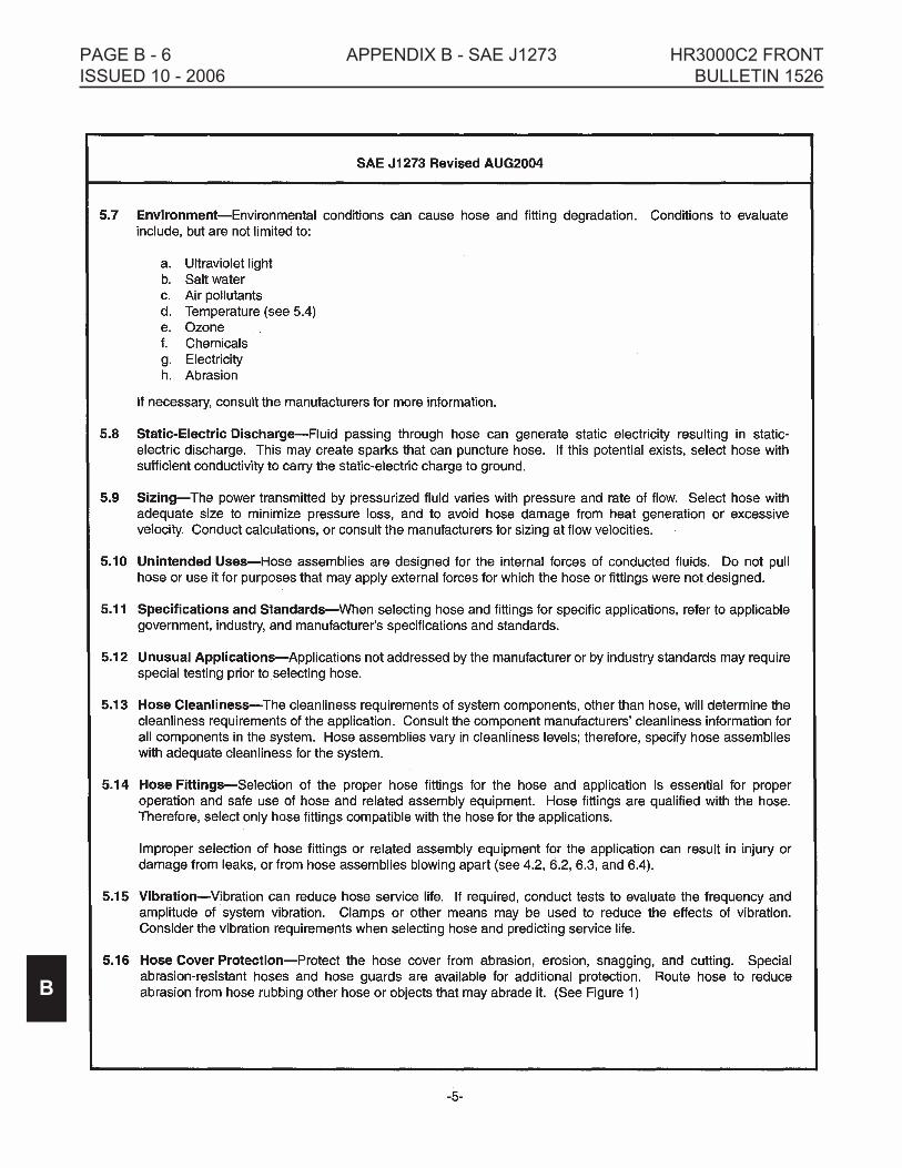
PAGE B - 6 APPENDIX B - SAE J1273 HR3000C2 FRONT
ISSUED 10 - 2006 BULLETIN 1526
B

HR3000C2 FRONT APPENDIX B - SAE J1273 PAGE B - 7
BULLETIN 1526 ISSUED 10 - 2006
B
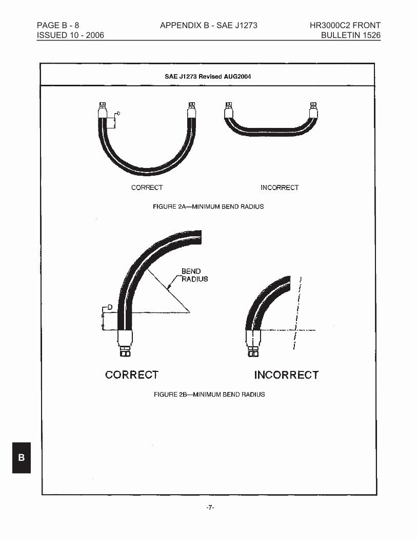
PAGE B - 8 APPENDIX B - SAE J1273 HR3000C2 FRONT
ISSUED 10 - 2006 BULLETIN 1526
B

HR3000C2 FRONT APPENDIX B - SAE J1273 PAGE B - 9
BULLETIN 1526 ISSUED 10 - 2006
B

PAGE B - 10 APPENDIX B - SAE J1273 HR3000C2 FRONT
ISSUED 10 - 2006 BULLETIN 1526
B

HR3000C2 FRONT APPENDIX B - SAE J1273 PAGE B - 11
BULLETIN 1526 ISSUED 10 - 2006
B

PAGE B - 12 APPENDIX B - SAE J1273 HR3000C2 FRONT
ISSUED 10 - 2006 BULLETIN 1526
B

HR3000C2 FRONT APPENDIX B - SAE J1273 PAGE B - 13
BULLETIN 1526 ISSUED 10 - 2006
B

PAGE B - 14 APPENDIX B - SAE J1273 HR3000C2 FRONT
ISSUED 10 - 2006 BULLETIN 1526
B

HR3000C2 FRONT APPENDIX B - SAE J1273 PAGE B - 15
BULLETIN 1526 ISSUED 10 - 2006
B
PAGE B - 16 APPENDIX B - SAE J1273 HR3000C2 FRONT
ISSUED 10 - 2006 BULLETIN 1526
B

HARSCO TRACK TECHNOLOGIES
TERMS AND CONDITIONS OF SALE
1. ACCEPTANCE OF TERMS AND CONDITIONS. The acceptance of the terms and conditions contained herein is an essential prerequisite to
any contract of sale made by HTT, a Division of Harsco Corporation (hereinafter “HTT”). Any offer or acceptance by HTT is made subject to the
terms and conditions contained herein and no additional or different terms offered by Buyer shall become a part of the agreement of sale between
HTT and Buyer unless such terms have been expressly approved in writing by an authorized agent of HTT. If this document is an offer, acceptance
of this offer is expressly limited to the terms hereof, and HTT reserves the right to withdraw this offer at any time before its acceptance by Buyer. If
this document has been issued by HTT in response to a written offer made by Buyer, HTT’s acceptance of Buyer’s offer is expressly conditioned on
Buyer’s assent to the additional or different terms contained herein. If these terms and conditions are not acceptable, Buyer shall notify HTT in
writing at once. Buyer’s action in (a) accepting any goods manufactured and delivered hereunder, or (b) receiving this document without
disaffirmance within three (3) business days of receipt shall constitute an unqualified acceptance by Buyer of the terms and conditions contained
herein.
2. INVOICES AND PAYMENT TERMS. Product shipments shall be invoiced based on the shipment date. Payment terms are as indicated in the
quotation letter and payment is due at HTT’s designated lockbox.
3. TAXES. Buyer shall pay to HTT the amount of any and all taxes, excises, or other charges (except income or gross receipt taxes) which HTT
may be required to pay to or to collect for any government, whether national, state or local, based upon or measured by the sale or use of the
Product sold hereunder provided the amount of the tax or other charge is set forth separately on HTT’s invoice.
4. DELIVERY. All delivery terms and dates are subject to the availability of the necessary shop space, transportation, and production hours.
5. FORCE MAJEURE. Neither HTT nor Buyer shall be liable for delay or failure to perform in whole or in part by reason of contingencies beyond
its control, whether herein specifically enumerated or not, including among others, acts of God, force majeure, war, acts of war, revolution, civil
commotion, riot, acts of public enemies, blockage or embargo, fire, explosion, breakdown of plant, strike, lockout, labor dispute, casualty or
accident, earthquake, epidemic, flood, cyclone, tornado, hurricane or other windstorm, lack or failure of sources of labor, power, supplies; lack, or
failure or excessive cost of raw materials which are used in the manufacture of Product by HTT, or by reason of any law, order, proclamation,
regulation, ordinance, demand, requisition or requirement or any other act of governmental authority, whether national, state or local, including
court orders, judgments, or decrees, or any other cause whatsoever, whether similar or dissimilar to those above enumerated, or actions of any
nature beyond the reasonable control of HTT or Buyer.
6. LIMITED WARRANTY. HTT warrants products of its manufacture to be free of defects in material and workmanship, under normal use and
service for a period of six (6) months from date of delivery to the original user. The obligation of HTT under this warranty is limited to repairing or
replacing at its factories, or other location designated by it, any part or parts thereof which are returned within 30 days of the date when failure occurs
or defect is noted, with transportation charges prepaid, and which upon examination appears to the satisfaction of HTT to have been defective.
Such free repair or replacement does not include transportation charges, or the cost of installing the new part or any other expense incident thereto.
HTT will not be liable for other loss, damage, or expense directly or indirectly arising from the use of its product, nor will HTT be liable for special,
incidental, or consequential damages. Ordinary wear and tear, and damage from abuse, misuse, neglect or alteration are not covered by this
warranty. HTT assumes no liability for expense incurred or repairs made outside its factories except by written consent. This warranty is null and
void if instructions and operating procedures are not followed. Equipment and parts not manufactured by HTT, but which are furnished in
connection with HTT products, are covered directly by the warranty of the manufacturer supplying them. However, HTT will assist in obtaining
adjustment on such equipment or parts when necessary. THIS WARRANTY IS IN LIEU OF ALL OTHER WARRANTIES EXPRESSED OR
IMPLIED INCLUDING ANY IMPLIED WARRANTIES OF MERCHANTABILITY OR FITNESS FOR A PARTICULAR PURPOSE, WHICH ARE
HEREBY DISCLAIMED AND OF ANY OTHER OBLIGATION OR LIABILITY OF HTT. THE REMEDY SET FORTH ABOVE IS BUYER’S
EXCLUSIVE REMEDY FOR A BREACH OF THE WARRANTY. UNDER NO CIRCUMSTANCES WILL HTT BE RESPONSIBLE FOR
INCIDENTAL, CONSEQUENTIAL, SPECIAL OR OTHER INDIRECT DAMAGES.
7. PRODUCT IMPROVEMENT LIABILITY DISCLAIMER. HTT reserves the right to make any changes in or improvements on its products
without incurring any liability or obligation whatsoever and without being required to make any corresponding changes or improvements in products
previously manufactured or sold.
8. INDEMNITY. Buyer agrees to indemnify and hold HTT harmless for all loss, cost including but not limited to legal and other cost of proceedings,
and damages suffered by Buyer or claimed by third parties by or related to Buyer’s use of HTT’s product.
9. HAZARDOUS MATERIAL DISCLAIMER. The parts/assemblies that are used in this Product are classified as “articles” according to 29 CFR
1910.1200 (C). They are formed to a specific shape or design during manufacture, have end use function dependent upon their shape or design,
and do not release any hazardous chemical under normal conditions of use. Accordingly, we are not required to supply Material Safety Data Sheets
(MSDS) or to label shipping containers for “articles”. However, lubricants, liquids, gaseous chemicals and solids used in operation or maintenance
of the product may require that user’s take occupational protective measures. MSDS sheets for such materials will be supplied to your Purchasing
Manager/Safety Director to be used in you employee safety training education and environmental health training.
10. TITLE AND RISK OF LOSS. Title to, ownership of, and risk of loss, destruction or damage to the Product shall pass to Buyer upon loading at
HTT’s plant.
11. CANCELLATION. No accepted purchase order may be modified except with HTT's prior written consent, nor may it be canceled except with
HTT’s prior written consent and by prior payment to HTT of a sum equal to the total of out-of-pocket expenses incurred in connection with the
purchase order, including but not limited to any charges made to HTT by suppliers for cancellation, plus a reasonable sum for overhead expenses
and lost profits, as determined by HTT.
12. SECURITY. HTT reserves the right to require payment in advance or satisfactory security or guaranty that an invoice will be promptly paid
when due if at any time Buyer's financial responsibility becomes impaired or unsatisfactory to HTT.
13. COSTS AND ATTORNEY’S FEES. Buyer shall pay all costs and reasonable attorneys' fees of HTT incurred in connection with the
enforcement of these terms of sale between the parties hereto.
14. EFFECT OF INVALIDITY. The invalidity in whole or in part of any provision hereof shall not affect the validity of any other provision.
15. WAIVER. No waiver by HTT of any breach of contract shall be deemed to be a waiver of any other or subsequent breach. All rights and
remedies available to HTT shall be cumulative and in addition to any other rights and remedies provided herein or by law.
16. Governing Law, Jurisdiction and Venue. These terms of sale between the parties hereto shall be governed by and construed in accordance
with the laws of the State of Pennsylvania. The parties agree that any controversy arising under the contract herein shall be determined by the
Courts of the State of Pennsylvania, and both parties hereby submit and consent to the jurisdiction of said Courts and agree that venue for any
action arising hereunder shall lie in Cumberland County, State of Pennsylvania.
VERSION DATE: June 2004

HARSCO TRACK TECHNOLOGIES
HARSCO CORPORATION
415 North Main Street
Fairmont, Minnesota, 56031-1837 U.S.A.
BULLETIN 1526 Printed In U.S.A. ISSUED 10 - 2006
© 2006 HARSCO TRACK TECHNOLOGIES, HARSCO CORPORATION