Embed Size (px)
Citation preview
FS; Reviewed:
SPOC 12/4/2009
Solution & Interoperability Test Lab Application Notes
©2009 Avaya Inc. All Rights Reserved.
1 of 58
NortelACASMMM
Avaya Solution & Interoperability Test Lab
Front-Ending Nortel Communication Server 1000 with an
AudioCodes Mediant 1000 Modular Media Gateway to
Support SIP Trunks to Avaya Aura™ Session Manager –
Issue 1.0
Abstract
These Application Notes present a sample configuration that uses an AudioCodes Mediant
1000 Modular Media Gateway as a PRI-QSIG/SIP gateway to connect Nortel Communication
Server 1000 with Avaya Aura™ Session Manager, which in turn provides call routing support
to other Avaya SIP products such as Avaya Aura™ Communication Manager 5.2 and Avaya
Modular Messaging.
For the sample configuration, Session Manager runs on an Avaya S8510 Server,
Communication Manager runs on an Avaya S8720 Server with Avaya G650 Media Gateway,
and Nortel Communication Server 1000 runs on Nortel Communication Server 1000S. The
results in these Application Notes should be applicable to other Avaya servers and media
gateways that support Communication Manager.
FS; Reviewed:
SPOC 12/4/2009
Solution & Interoperability Test Lab Application Notes
©2009 Avaya Inc. All Rights Reserved.
2 of 58
NortelACASMMM
1 Introduction Previous Avaya Application Notes [9] describe how Release 4.5 Nortel Communication Server
1000 can be directly integrated with Session Manager using SIP trunks. While effective in terms
of supporting basic and supplementary call features, this configuration does have some
limitations in areas such as DTMF support and call coverage1. There are also many installations
of Nortel Communication Server 1000 which are not SIP or IP capable. In these cases, an
effective solution is to front-end the Nortel Communication Server 1000 with a PRI-QSIG/SIP
gateway, which then signals on SIP trunks to Session Manager. This configuration supports basic
and supplementary call features as well as RFC 2833 DTMF and message-waiting signaling for
applications such as voice messaging.
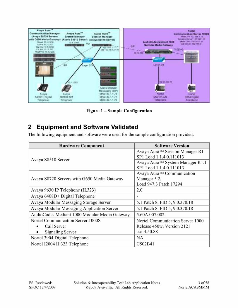
Figure 1 shows a sample configuration that uses an AudioCodes Mediant 1000 Modular Media
Gateway to front-end the Nortel Communication Server 1000 via a T1/PRI QSIG connection.
The Mediant 1000 supports SIP trunks to the SM-100 (Security Module) network interface of
Session Manager, which in turn performs call routing to Communication Manager and Modular
Messaging. Session Manager can support flexible inter-system call routing based on dialed
number, calling number and system location, and can also provide protocol adaptation to allow
multi-vendor systems to interoperate. It is managed by a separate Avaya Aura™ System
Manager, which can manage multiple Session Managers by communicating with their
management network interfaces. Modular Messaging expands the capabilities and features of
messaging services. Centralized messaging enables the local Modular Messaging system to
provide voicemail service to subscribers at both sites in a multi-site configuration.
For the sample configuration, Session Manager runs on an Avaya S8510 Server, Communication
Manager runs on an Avaya S8720 Server with Avaya G650 Media Gateway, and Nortel
Communication Server 1000 runs on Nortel Communication Server 1000S. These Application
Notes should apply to other Avaya servers and Media Gateways.
As shown in Figure 1, the Avaya 9630 IP Telephone (H.323) and 6408D+ Digital Telephone are
supported by Communication Manager. The Nortel i2004 H.323 Telephone and 3904 Digital
Telephone are supported by Nortel Communication Server 1000. A five digit Uniform Dial Plan
(UDP) is used for dialing between systems. Unique extension ranges are associated with
Communication Manager (3xxxx) and Nortel Communication Server 1000 (53xxx). Session
Manager routes calls based on this five digit plan, using an adaptation module to convert to the
normalized eleven digit plan used in Modular Messaging.
These Application Notes will focus on configuration of the QSIG trunks, SIP trunks, dial plan
support, call routing, and call coverage for voice messaging. Detailed administration of the
endpoint telephones will not be described (see the appropriate documentation listed in Section
10). Configurations supporting SIP telephones still require Avaya Aura™ SIP Enablement
Services, and are not addressed here.
1 These limitations may be resolved in later releases of Nortel Communication Server 1000.
FS; Reviewed:
SPOC 12/4/2009
Solution & Interoperability Test Lab Application Notes
©2009 Avaya Inc. All Rights Reserved.
3 of 58
NortelACASMMM
Figure 1 – Sample Configuration
2 Equipment and Software Validated The following equipment and software were used for the sample configuration provided:
Hardware Component Software Version
Avaya S8510 Server
Avaya Aura™ Session Manager R1
SP1 Load 1.1.4.0.111013
Avaya Aura™ System Manager R1.1
SP1 Load 1.1.4.0.111013
Avaya S8720 Servers with G650 Media Gateway
Avaya Aura™ Communication
Manager 5.2,
Load 947.3 Patch 17294
Avaya 9630 IP Telephone (H.323) 2.0
Avaya 6408D+ Digital Telephone -
Avaya Modular Messaging Storage Server 5.1 Patch 8, FID 5, 9.0.370.18
Avaya Modular Messaging Application Server 5.1 Patch 8, FID 5, 9.0.370.18
AudioCodes Mediant 1000 Modular Media Gateway 5.60A.007.002
Nortel Communication Server 1000S
• Call Server
• Signaling Server
Nortel Communication Server 1000
Release 450w, Version 2121
sse-4.50.88
Nortel 3904 Digital Telephone NA
Nortel I2004 H.323 Telephone C502B41
FS; Reviewed:
SPOC 12/4/2009
Solution & Interoperability Test Lab Application Notes
©2009 Avaya Inc. All Rights Reserved.
4 of 58
NortelACASMMM
3 Configure Communication Manager This section describes configuring Communication Manager in the following areas. Some
administration screens have been abbreviated for clarity.
• Communication Manager license
• System parameters features
• IP node names
• IP interface
• IP codec set and network region
• SIP signaling group and trunk group
• Route pattern
• Location and public unknown numbering
• Uniform dial plan and AAR analysis
• Voice messaging hunt group
• Voice messaging coverage path
• Sample station form specifying voice messaging coverage path
3.1 Verify Communication Manager License
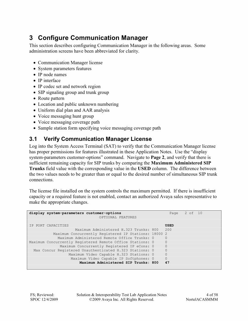
Log into the System Access Terminal (SAT) to verify that the Communication Manager license
has proper permissions for features illustrated in these Application Notes. Use the “display
system-parameters customer-options” command. Navigate to Page 2, and verify that there is
sufficient remaining capacity for SIP trunks by comparing the Maximum Administered SIP
Trunks field value with the corresponding value in the USED column. The difference between
the two values needs to be greater than or equal to the desired number of simultaneous SIP trunk
connections.
The license file installed on the system controls the maximum permitted. If there is insufficient
capacity or a required feature is not enabled, contact an authorized Avaya sales representative to
make the appropriate changes.
display system-parameters customer-options Page 2 of 10 OPTIONAL FEATURES IP PORT CAPACITIES USED Maximum Administered H.323 Trunks: 800 200 Maximum Concurrently Registered IP Stations: 18000 2 Maximum Administered Remote Office Trunks: 0 0 Maximum Concurrently Registered Remote Office Stations: 0 0 Maximum Concurrently Registered IP eCons: 0 0 Max Concur Registered Unauthenticated H.323 Stations: 0 0 Maximum Video Capable H.323 Stations: 0 0 Maximum Video Capable IP Softphones: 0 0 Maximum Administered SIP Trunks: 800 47
FS; Reviewed:
SPOC 12/4/2009
Solution & Interoperability Test Lab Application Notes
©2009 Avaya Inc. All Rights Reserved.
5 of 58
NortelACASMMM
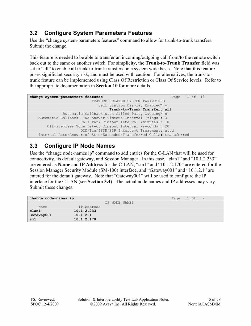
3.2 Configure System Parameters Features
Use the “change system-parameters features” command to allow for trunk-to-trunk transfers.
Submit the change.
This feature is needed to be able to transfer an incoming/outgoing call from/to the remote switch
back out to the same or another switch For simplicity, the Trunk-to-Trunk Transfer field was
set to “all” to enable all trunk-to-trunk transfers on a system wide basis. Note that this feature
poses significant security risk, and must be used with caution. For alternatives, the trunk-to-
trunk feature can be implemented using Class Of Restriction or Class Of Service levels. Refer to
the appropriate documentation in Section 10 for more details.
change system-parameters features Page 1 of 18 FEATURE-RELATED SYSTEM PARAMETERS Self Station Display Enabled? y Trunk-to-Trunk Transfer: all Automatic Callback with Called Party Queuing? n Automatic Callback - No Answer Timeout Interval (rings): 3 Call Park Timeout Interval (minutes): 10 Off-Premises Tone Detect Timeout Interval (seconds): 20 DID/Tie/ISDN/SIP Intercept Treatment: attd Internal Auto-Answer of Attd-Extended/Transferred Calls: transferred
3.3 Configure IP Node Names
Use the “change node-names ip” command to add entries for the C-LAN that will be used for
connectivity, its default gateway, and Session Manager. In this case, “clan1” and “10.1.2.233”
are entered as Name and IP Address for the C-LAN, “sm1” and “10.1.2.170” are entered for the
Session Manager Security Module (SM-100) interface, and “Gateway001” and “10.1.2.1” are
entered for the default gateway. Note that “Gateway001” will be used to configure the IP
interface for the C-LAN (see Section 3.4). The actual node names and IP addresses may vary.
Submit these changes.
change node-names ip Page 1 of 2 IP NODE NAMES Name IP Address clan1 10.1.2.233 Gateway001 10.1.2.1
sm1 10.1.2.170
FS; Reviewed:
SPOC 12/4/2009
Solution & Interoperability Test Lab Application Notes
©2009 Avaya Inc. All Rights Reserved.
6 of 58
NortelACASMMM
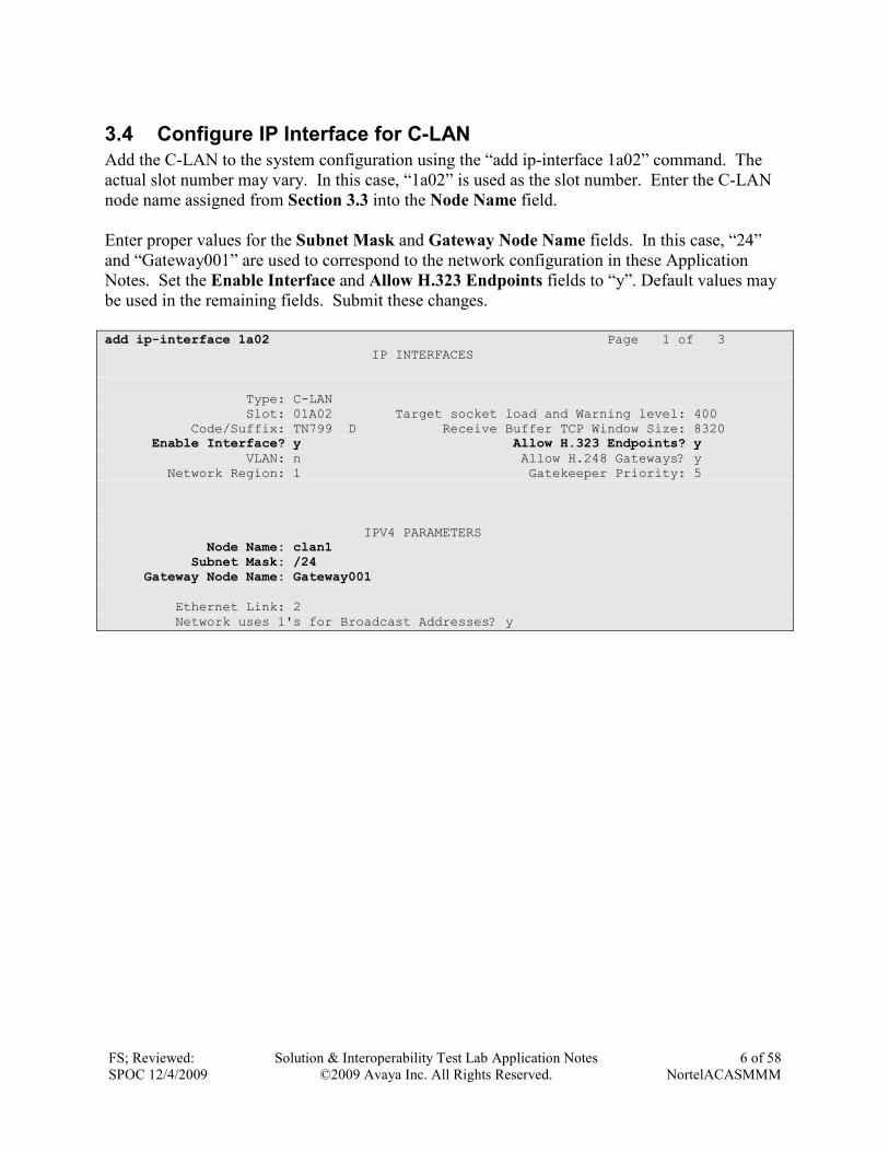
3.4 Configure IP Interface for C-LAN
Add the C-LAN to the system configuration using the “add ip-interface 1a02” command. The
actual slot number may vary. In this case, “1a02” is used as the slot number. Enter the C-LAN
node name assigned from Section 3.3 into the Node Name field.
Enter proper values for the Subnet Mask and Gateway Node Name fields. In this case, “24”
and “Gateway001” are used to correspond to the network configuration in these Application
Notes. Set the Enable Interface and Allow H.323 Endpoints fields to “y”. Default values may
be used in the remaining fields. Submit these changes.
add ip-interface 1a02 Page 1 of 3 IP INTERFACES Type: C-LAN Slot: 01A02 Target socket load and Warning level: 400 Code/Suffix: TN799 D Receive Buffer TCP Window Size: 8320 Enable Interface? y Allow H.323 Endpoints? y VLAN: n Allow H.248 Gateways? y Network Region: 1 Gatekeeper Priority: 5 IPV4 PARAMETERS Node Name: clan1 Subnet Mask: /24 Gateway Node Name: Gateway001
Ethernet Link: 2 Network uses 1's for Broadcast Addresses? y
FS; Reviewed:
SPOC 12/4/2009
Solution & Interoperability Test Lab Application Notes
©2009 Avaya Inc. All Rights Reserved.
7 of 58
NortelACASMMM
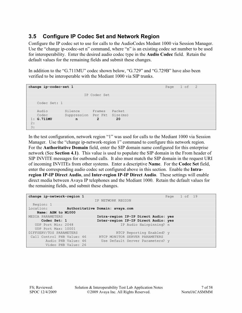
3.5 Configure IP Codec Set and Network Region
Configure the IP codec set to use for calls to the AudioCodes Medant 1000 via Session Manager.
Use the “change ip-codec-set n” command, where “n” is an existing codec set number to be used
for interoperability. Enter the desired audio codec type in the Audio Codec field. Retain the
default values for the remaining fields and submit these changes.
In addition to the “G.711MU” codec shown below, “G.729” and “G.729B” have also been
verified to be interoperable with the Mediant 1000 via SIP trunks.
change ip-codec-set 1 Page 1 of 2 IP Codec Set Codec Set: 1 Audio Silence Frames Packet Codec Suppression Per Pkt Size(ms) 1: G.711MU n 2 20 2: 3:
In the test configuration, network region “1” was used for calls to the Mediant 1000 via Session
Manager. Use the “change ip-network-region 1” command to configure this network region.
For the Authoritative Domain field, enter the SIP domain name configured for this enterprise
network (See Section 4.1). This value is used to populate the SIP domain in the From header of
SIP INVITE messages for outbound calls. It also must match the SIP domain in the request URI
of incoming INVITEs from other systems. Enter a descriptive Name. For the Codec Set field,
enter the corresponding audio codec set configured above in this section. Enable the Intra-
region IP-IP Direct Audio, and Inter-region IP-IP Direct Audio. These settings will enable
direct media between Avaya IP telephones and the Mediant 1000. Retain the default values for
the remaining fields, and submit these changes.
change ip-network-region 1 Page 1 of 19 IP NETWORK REGION Region: 1 Location: Authoritative Domain: avaya.com Name: ASM to M1000 MEDIA PARAMETERS Intra-region IP-IP Direct Audio: yes Codec Set: 1 Inter-region IP-IP Direct Audio: yes UDP Port Min: 2048 IP Audio Hairpinning? n UDP Port Max: 10001 DIFFSERV/TOS PARAMETERS RTCP Reporting Enabled? y Call Control PHB Value: 46 RTCP MONITOR SERVER PARAMETERS Audio PHB Value: 46 Use Default Server Parameters? y Video PHB Value: 26
FS; Reviewed:
SPOC 12/4/2009
Solution & Interoperability Test Lab Application Notes
©2009 Avaya Inc. All Rights Reserved.
8 of 58
NortelACASMMM
3.6 Configure SIP Signaling Group and Trunk Group
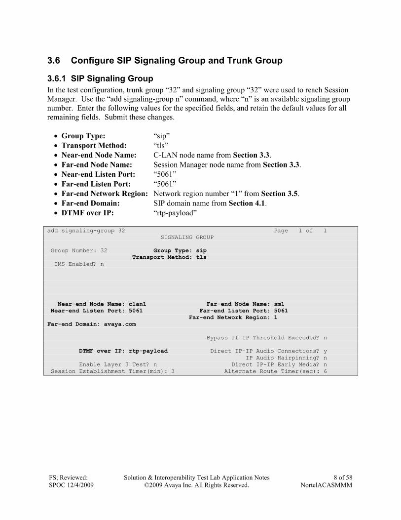
3.6.1 SIP Signaling Group
In the test configuration, trunk group “32” and signaling group “32” were used to reach Session
Manager. Use the “add signaling-group n” command, where “n” is an available signaling group
number. Enter the following values for the specified fields, and retain the default values for all
remaining fields. Submit these changes.
• Group Type: “sip”
• Transport Method: “tls”
• Near-end Node Name: C-LAN node name from Section 3.3.
• Far-end Node Name: Session Manager node name from Section 3.3.
• Near-end Listen Port: “5061”
• Far-end Listen Port: “5061”
• Far-end Network Region: Network region number “1” from Section 3.5.
• Far-end Domain: SIP domain name from Section 4.1.
• DTMF over IP: “rtp-payload”
add signaling-group 32 Page 1 of 1 SIGNALING GROUP Group Number: 32 Group Type: sip Transport Method: tls IMS Enabled? n Near-end Node Name: clan1 Far-end Node Name: sm1 Near-end Listen Port: 5061 Far-end Listen Port: 5061 Far-end Network Region: 1 Far-end Domain: avaya.com
Bypass If IP Threshold Exceeded? n DTMF over IP: rtp-payload Direct IP-IP Audio Connections? y IP Audio Hairpinning? n Enable Layer 3 Test? n Direct IP-IP Early Media? n Session Establishment Timer(min): 3 Alternate Route Timer(sec): 6
FS; Reviewed:
SPOC 12/4/2009
Solution & Interoperability Test Lab Application Notes
©2009 Avaya Inc. All Rights Reserved.
9 of 58
NortelACASMMM
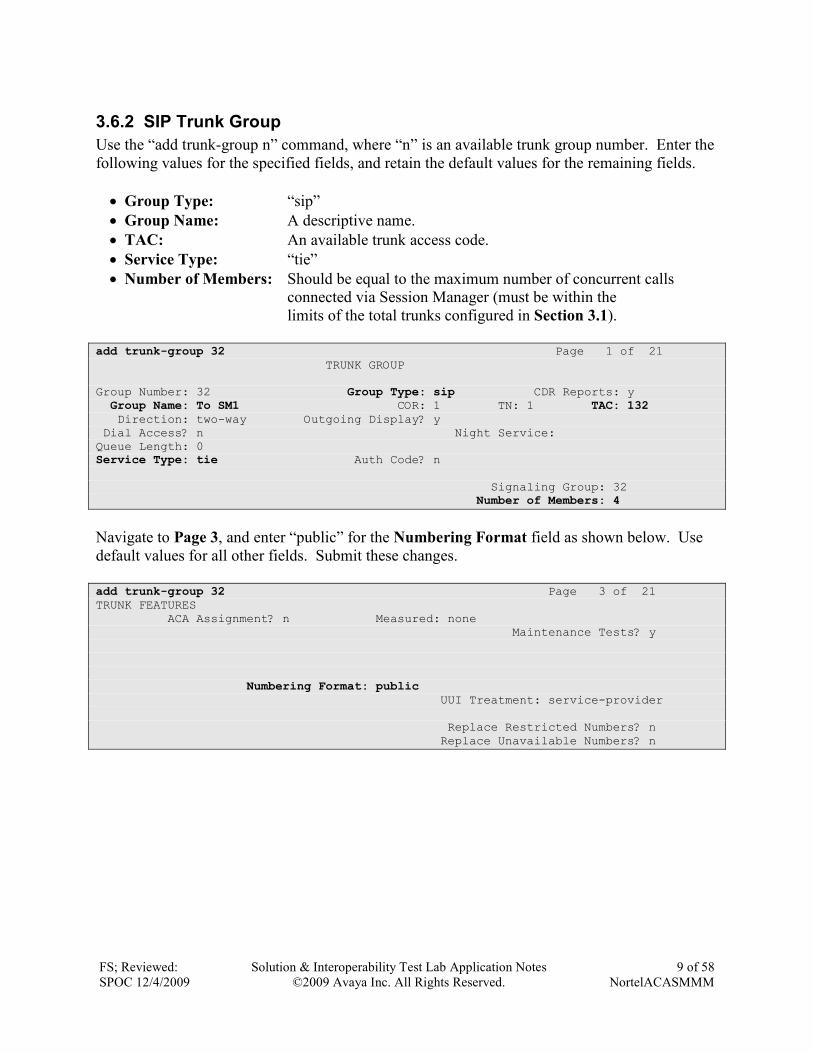
3.6.2 SIP Trunk Group
Use the “add trunk-group n” command, where “n” is an available trunk group number. Enter the
following values for the specified fields, and retain the default values for the remaining fields.
• Group Type: “sip”
• Group Name: A descriptive name.
• TAC: An available trunk access code.
• Service Type: “tie”
• Number of Members: Should be equal to the maximum number of concurrent calls
connected via Session Manager (must be within the
limits of the total trunks configured in Section 3.1).
add trunk-group 32 Page 1 of 21 TRUNK GROUP Group Number: 32 Group Type: sip CDR Reports: y Group Name: To SM1 COR: 1 TN: 1 TAC: 132 Direction: two-way Outgoing Display? y Dial Access? n Night Service: Queue Length: 0 Service Type: tie Auth Code? n Signaling Group: 32 Number of Members: 4
Navigate to Page 3, and enter “public” for the Numbering Format field as shown below. Use
default values for all other fields. Submit these changes.
add trunk-group 32 Page 3 of 21 TRUNK FEATURES ACA Assignment? n Measured: none Maintenance Tests? y Numbering Format: public UUI Treatment: service-provider Replace Restricted Numbers? n Replace Unavailable Numbers? n
FS; Reviewed:
SPOC 12/4/2009
Solution & Interoperability Test Lab Application Notes
©2009 Avaya Inc. All Rights Reserved.
10 of 58
NortelACASMMM
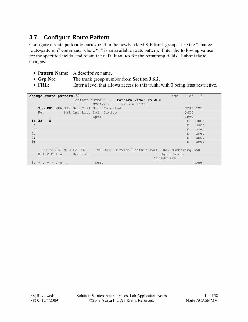
3.7 Configure Route Pattern
Configure a route pattern to correspond to the newly added SIP trunk group. Use the “change
route-pattern n” command, where “n” is an available route pattern. Enter the following values
for the specified fields, and retain the default values for the remaining fields. Submit these
changes.
• Pattern Name: A descriptive name.
• Grp No: The trunk group number from Section 3.6.2.
• FRL: Enter a level that allows access to this trunk, with 0 being least restrictive.
change route-pattern 32 Page 1 of 3 Pattern Number: 32 Pattern Name: To ASM SCCAN? n Secure SIP? n Grp FRL NPA Pfx Hop Toll No. Inserted DCS/ IXC No Mrk Lmt List Del Digits QSIG Dgts Intw 1: 32 0 n user 2: n user 3: n user 4: n user 5: n user 6: n user BCC VALUE TSC CA-TSC ITC BCIE Service/Feature PARM No. Numbering LAR 0 1 2 M 4 W Request Dgts Format Subaddress 1: y y y y y n n rest none
FS; Reviewed:
SPOC 12/4/2009
Solution & Interoperability Test Lab Application Notes
©2009 Avaya Inc. All Rights Reserved.
11 of 58
NortelACASMMM
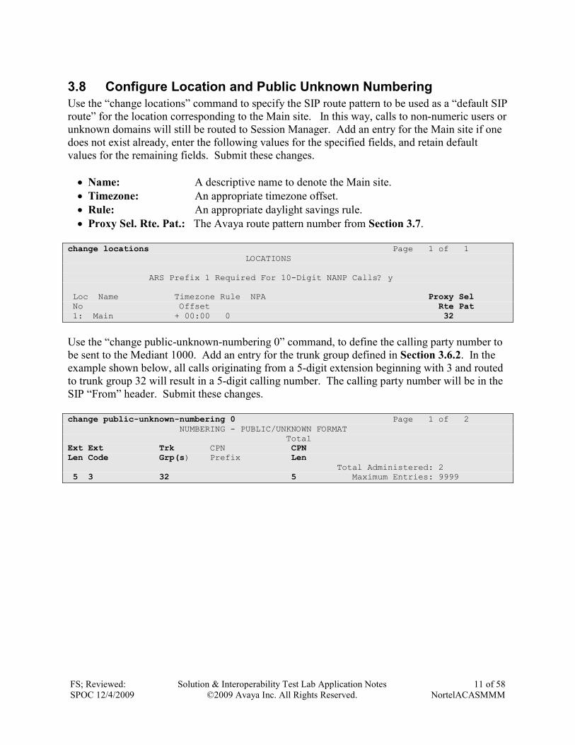
3.8 Configure Location and Public Unknown Numbering
Use the “change locations” command to specify the SIP route pattern to be used as a “default SIP
route” for the location corresponding to the Main site. In this way, calls to non-numeric users or
unknown domains will still be routed to Session Manager. Add an entry for the Main site if one
does not exist already, enter the following values for the specified fields, and retain default
values for the remaining fields. Submit these changes.
• Name: A descriptive name to denote the Main site.
• Timezone: An appropriate timezone offset.
• Rule: An appropriate daylight savings rule.
• Proxy Sel. Rte. Pat.: The Avaya route pattern number from Section 3.7.
change locations Page 1 of 1 LOCATIONS ARS Prefix 1 Required For 10-Digit NANP Calls? y Loc Name Timezone Rule NPA Proxy Sel No Offset Rte Pat 1: Main + 00:00 0 32
Use the “change public-unknown-numbering 0” command, to define the calling party number to
be sent to the Mediant 1000. Add an entry for the trunk group defined in Section 3.6.2. In the
example shown below, all calls originating from a 5-digit extension beginning with 3 and routed
to trunk group 32 will result in a 5-digit calling number. The calling party number will be in the
SIP “From” header. Submit these changes.
change public-unknown-numbering 0 Page 1 of 2 NUMBERING - PUBLIC/UNKNOWN FORMAT Total Ext Ext Trk CPN CPN Len Code Grp(s) Prefix Len Total Administered: 2 5 3 32 5 Maximum Entries: 9999
FS; Reviewed:
SPOC 12/4/2009
Solution & Interoperability Test Lab Application Notes
©2009 Avaya Inc. All Rights Reserved.
12 of 58
NortelACASMMM
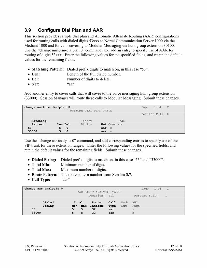
3.9 Configure Dial Plan and AAR
This section provides sample dial plan and Automatic Alternate Routing (AAR) configurations
used for routing calls with dialed digits 53xxx to Nortel Communication Server 1000 via the
Mediant 1000 and for calls covering to Modular Messaging via hunt group extension 30100.
Use the “change uniform-dialplan 0” command, and add an entry to specify use of AAR for
routing of digits 53xxx. Enter the following values for the specified fields, and retain the default
values for the remaining fields.
• Matching Pattern: Dialed prefix digits to match on, in this case “53”.
• Len: Length of the full dialed number.
• Del: Number of digits to delete.
• Net: “aar”
Add another entry to cover calls that will cover to the voice messaging hunt group extension
(33000). Session Manager will route these calls to Modular Messaging. Submit these changes.
change uniform-dialplan 0 Page 1 of 2 UNIFORM DIAL PLAN TABLE Percent Full: 0 Matching Insert Node Pattern Len Del Digits Net Conv Num 53 5 0 aar n 33000 5 0 aar n
Use the “change aar analysis 0” command, and add corresponding entries to specify use of the
SIP trunk for these extension ranges. Enter the following values for the specified fields, and
retain the default values for the remaining fields. Submit these changes.
• Dialed String: Dialed prefix digits to match on, in this case “53” and “33000”.
• Total Min: Minimum number of digts.
• Total Max: Maximum number of digits.
• Route Pattern: The route pattern number from Section 3.7.
• Call Type: “aar”
change aar analysis 0 Page 1 of 2 AAR DIGIT ANALYSIS TABLE Location: all Percent Full: 1 Dialed Total Route Call Node ANI String Min Max Pattern Type Num Reqd 53 5 5 32 aar n 33000 5 5 32 aar n
FS; Reviewed:
SPOC 12/4/2009
Solution & Interoperability Test Lab Application Notes
©2009 Avaya Inc. All Rights Reserved.
13 of 58
NortelACASMMM
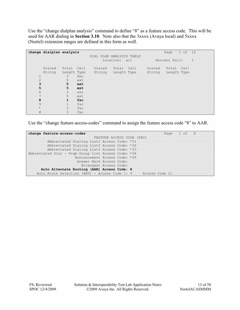
Use the “change dialplan analysis” command to define “8” as a feature access code. This will be
used for AAR dialing in Section 3.10. Note also that the 3xxxx (Avaya local) and 5xxxx
(Nortel) extension ranges are defined in this form as well.
change dialplan analysis Page 1 of 12 DIAL PLAN ANALYSIS TABLE Location: all Percent Full: 1 Dialed Total Call Dialed Total Call Dialed Total Call String Length Type String Length Type String Length Type 1 3 dac 2 5 ext 3 5 ext 5 5 ext
6 5 ext 7 5 ext 8 1 fac 9 1 fac * 3 fac # 3 fac
Use the “change feature-access-codes” command to assign the feature access code “8” to AAR.
change feature-access-codes Page 1 of 8 FEATURE ACCESS CODE (FAC) Abbreviated Dialing List1 Access Code: *01 Abbreviated Dialing List2 Access Code: *02 Abbreviated Dialing List3 Access Code: *03 Abbreviated Dial - Prgm Group List Access Code: *04 Announcement Access Code: *05 Answer Back Access Code: Attendant Access Code: Auto Alternate Routing (AAR) Access Code: 8 Auto Route Selection (ARS) - Access Code 1: 9 Access Code 2:
FS; Reviewed:
SPOC 12/4/2009
Solution & Interoperability Test Lab Application Notes
©2009 Avaya Inc. All Rights Reserved.
14 of 58
NortelACASMMM
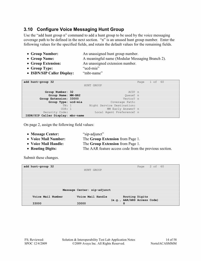
3.10 Configure Voice Messaging Hunt Group
Use the “add hunt group n” command to add a hunt group to be used by the voice messaging
coverage path to be defined in the next section. “n” is an unused hunt group number. Enter the
following values for the specified fields, and retain the default values for the remaining fields.
• Group Number: An unassigned hunt group number.
• Group Name: A meaningful name (Modular Messaging Branch 2).
• Group Extension: An unassigned extension number.
• Group Type: “ucd-mia”
• ISDN/SIP Caller Display: “mbr-name”
add hunt-group 32 Page 1 of 60 HUNT GROUP Group Number: 32 ACD? n Group Name: MM-BR2 Queue? n Group Extension: 33000 Vector? n Group Type: ucd-mia Coverage Path: TN: 1 Night Service Destination: COR: 1 MM Early Answer? n Security Code: Local Agent Preference? n ISDN/SIP Caller Display: mbr-name
On page 2, assign the following field values:
• Message Center: “sip-adjunct”
• Voice Mail Number: The Group Extension from Page 1.
• Voice Mail Handle: The Group Extension from Page 1.
• Routing Digits: The AAR feature access code from the previous section.
Submit these changes.
add hunt-group 32 Page 2 of 60 HUNT GROUP Message Center: sip-adjunct Voice Mail Number Voice Mail Handle Routing Digits (e.g., AAR/ARS Access Code)
33000 33000 8
FS; Reviewed:
SPOC 12/4/2009
Solution & Interoperability Test Lab Application Notes
©2009 Avaya Inc. All Rights Reserved.
15 of 58
NortelACASMMM
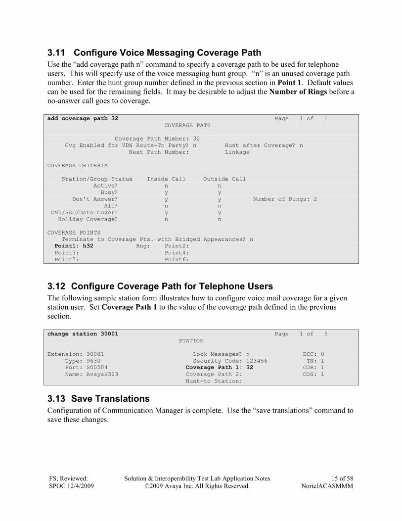
3.11 Configure Voice Messaging Coverage Path
Use the “add coverage path n” command to specify a coverage path to be used for telephone
users. This will specify use of the voice messaging hunt group. “n” is an unused coverage path
number. Enter the hunt group number defined in the previous section in Point 1. Default values
can be used for the remaining fields. It may be desirable to adjust the Number of Rings before a
no-answer call goes to coverage.
add coverage path 32 Page 1 of 1 COVERAGE PATH Coverage Path Number: 32 Cvg Enabled for VDN Route-To Party? n Hunt after Coverage? n Next Path Number: Linkage COVERAGE CRITERIA Station/Group Status Inside Call Outside Call Active? n n Busy? y y Don't Answer? y y Number of Rings: 2 All? n n DND/SAC/Goto Cover? y y Holiday Coverage? n n COVERAGE POINTS Terminate to Coverage Pts. with Bridged Appearances? n Point1: h32 Rng: Point2: Point3: Point4: Point5: Point6:
3.12 Configure Coverage Path for Telephone Users
The following sample station form illustrates how to configure voice mail coverage for a given
station user. Set Coverage Path 1 to the value of the coverage path defined in the previous
section.
change station 30001 Page 1 of 5 STATION Extension: 30001 Lock Messages? n BCC: 0 Type: 9630 Security Code: 123456 TN: 1 Port: S00504 Coverage Path 1: 32 COR: 1 Name: AvayaH323 Coverage Path 2: COS: 1 Hunt-to Station:
3.13 Save Translations
Configuration of Communication Manager is complete. Use the “save translations” command to
save these changes.
FS; Reviewed:
SPOC 12/4/2009
Solution & Interoperability Test Lab Application Notes
©2009 Avaya Inc. All Rights Reserved.
16 of 58
NortelACASMMM
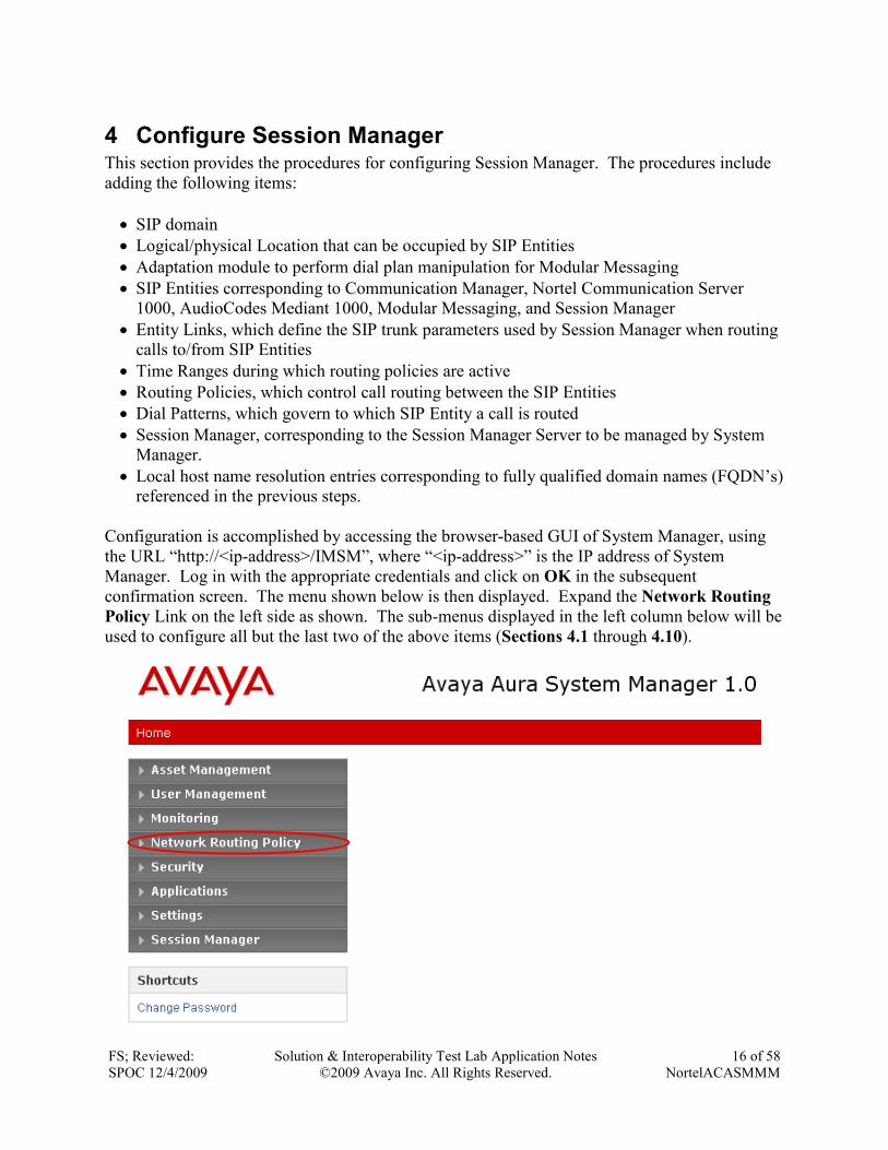
4 Configure Session Manager This section provides the procedures for configuring Session Manager. The procedures include
adding the following items:
• SIP domain
• Logical/physical Location that can be occupied by SIP Entities
• Adaptation module to perform dial plan manipulation for Modular Messaging
• SIP Entities corresponding to Communication Manager, Nortel Communication Server
1000, AudioCodes Mediant 1000, Modular Messaging, and Session Manager
• Entity Links, which define the SIP trunk parameters used by Session Manager when routing
calls to/from SIP Entities
• Time Ranges during which routing policies are active
• Routing Policies, which control call routing between the SIP Entities
• Dial Patterns, which govern to which SIP Entity a call is routed
• Session Manager, corresponding to the Session Manager Server to be managed by System
Manager.
• Local host name resolution entries corresponding to fully qualified domain names (FQDN’s)
referenced in the previous steps.
Configuration is accomplished by accessing the browser-based GUI of System Manager, using
the URL “http://<ip-address>/IMSM”, where “<ip-address>” is the IP address of System
Manager. Log in with the appropriate credentials and click on OK in the subsequent
confirmation screen. The menu shown below is then displayed. Expand the Network Routing
Policy Link on the left side as shown. The sub-menus displayed in the left column below will be
used to configure all but the last two of the above items (Sections 4.1 through 4.10).
FS; Reviewed:
SPOC 12/4/2009
Solution & Interoperability Test Lab Application Notes
©2009 Avaya Inc. All Rights Reserved.
17 of 58
NortelACASMMM
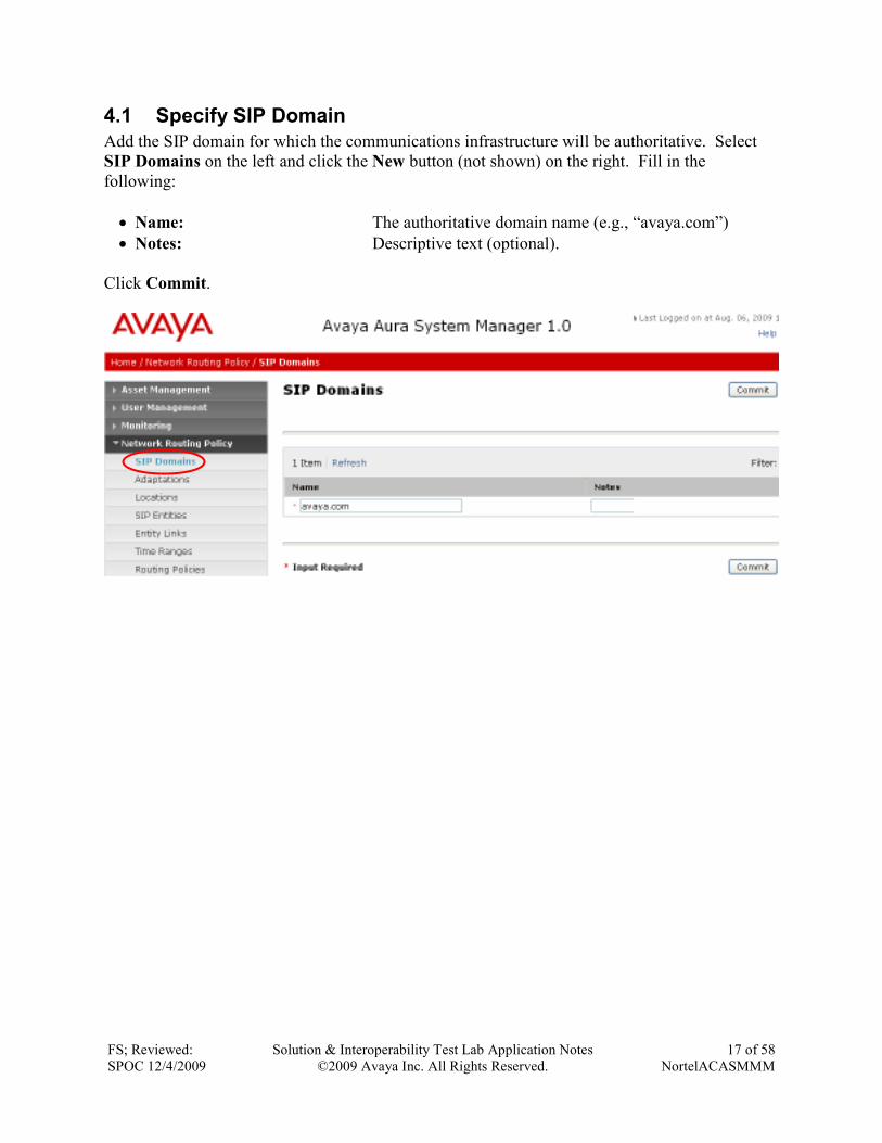
4.1 Specify SIP Domain
Add the SIP domain for which the communications infrastructure will be authoritative. Select
SIP Domains on the left and click the New button (not shown) on the right. Fill in the
following:
• Name: The authoritative domain name (e.g., “avaya.com”)
• Notes: Descriptive text (optional).
Click Commit.
FS; Reviewed:
SPOC 12/4/2009
Solution & Interoperability Test Lab Application Notes
©2009 Avaya Inc. All Rights Reserved.
18 of 58
NortelACASMMM
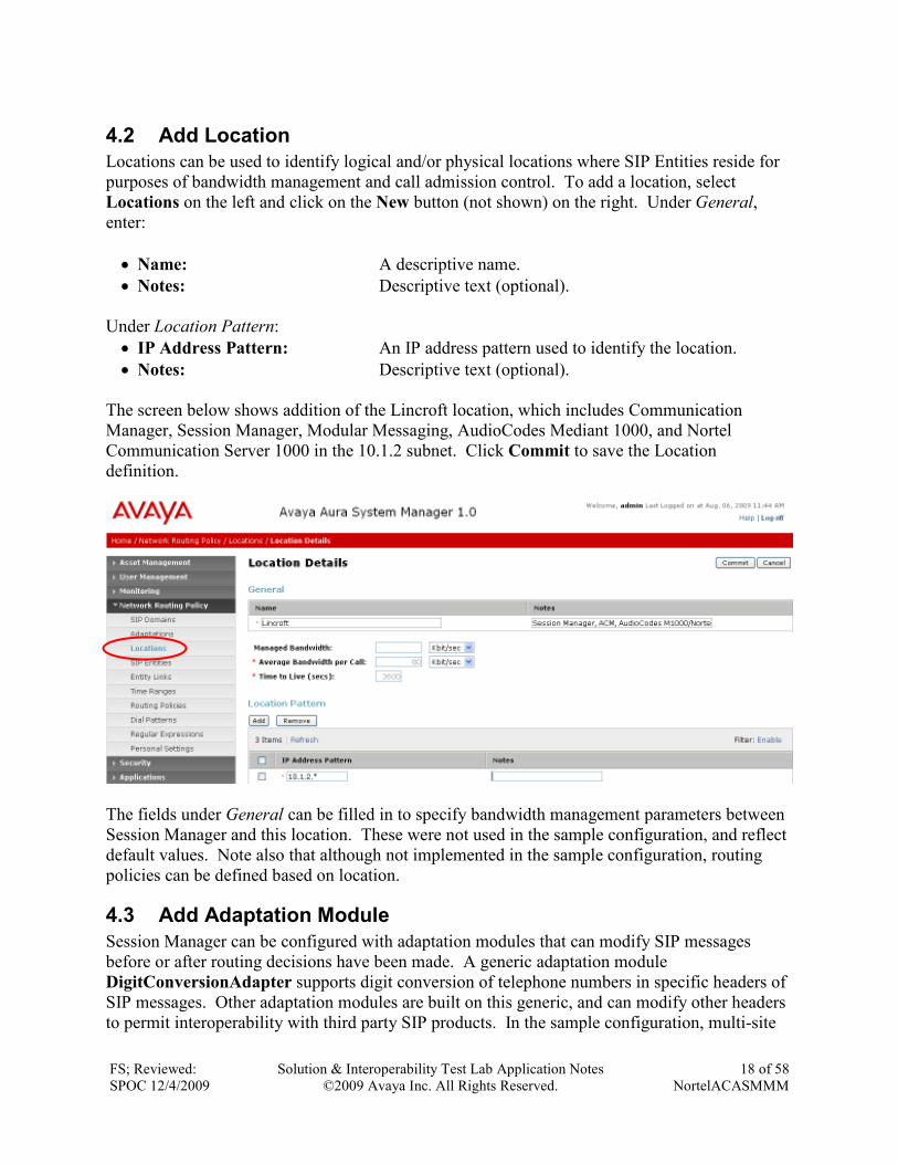
4.2 Add Location
Locations can be used to identify logical and/or physical locations where SIP Entities reside for
purposes of bandwidth management and call admission control. To add a location, select
Locations on the left and click on the New button (not shown) on the right. Under General,
enter:
• Name: A descriptive name.
• Notes: Descriptive text (optional).
Under Location Pattern:
• IP Address Pattern: An IP address pattern used to identify the location.
• Notes: Descriptive text (optional).
The screen below shows addition of the Lincroft location, which includes Communication
Manager, Session Manager, Modular Messaging, AudioCodes Mediant 1000, and Nortel
Communication Server 1000 in the 10.1.2 subnet. Click Commit to save the Location
definition.
The fields under General can be filled in to specify bandwidth management parameters between
Session Manager and this location. These were not used in the sample configuration, and reflect
default values. Note also that although not implemented in the sample configuration, routing
policies can be defined based on location.
4.3 Add Adaptation Module
Session Manager can be configured with adaptation modules that can modify SIP messages
before or after routing decisions have been made. A generic adaptation module
DigitConversionAdapter supports digit conversion of telephone numbers in specific headers of
SIP messages. Other adaptation modules are built on this generic, and can modify other headers
to permit interoperability with third party SIP products. In the sample configuration, multi-site
FS; Reviewed:
SPOC 12/4/2009
Solution & Interoperability Test Lab Application Notes
©2009 Avaya Inc. All Rights Reserved.
19 of 58
NortelACASMMM
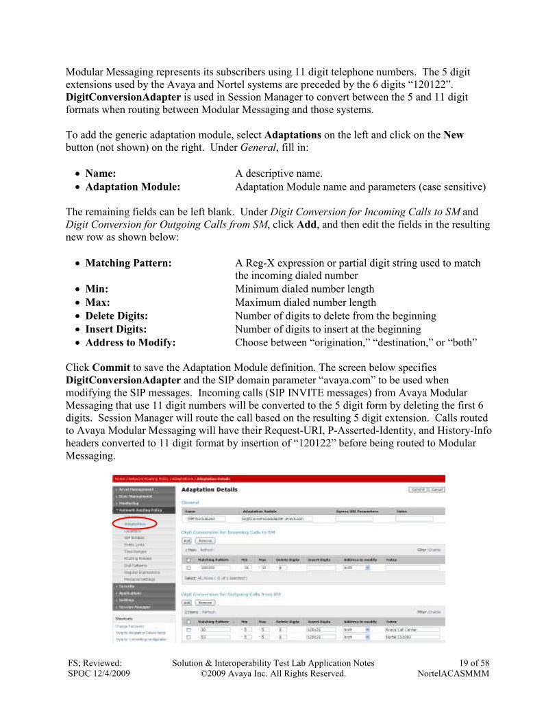
Modular Messaging represents its subscribers using 11 digit telephone numbers. The 5 digit
extensions used by the Avaya and Nortel systems are preceded by the 6 digits “120122”.
DigitConversionAdapter is used in Session Manager to convert between the 5 and 11 digit
formats when routing between Modular Messaging and those systems.
To add the generic adaptation module, select Adaptations on the left and click on the New
button (not shown) on the right. Under General, fill in:
• Name: A descriptive name.
• Adaptation Module: Adaptation Module name and parameters (case sensitive)
The remaining fields can be left blank. Under Digit Conversion for Incoming Calls to SM and
Digit Conversion for Outgoing Calls from SM, click Add, and then edit the fields in the resulting
new row as shown below:
• Matching Pattern: A Reg-X expression or partial digit string used to match
the incoming dialed number
• Min: Minimum dialed number length
• Max: Maximum dialed number length
• Delete Digits: Number of digits to delete from the beginning
• Insert Digits: Number of digits to insert at the beginning
• Address to Modify: Choose between “origination,” “destination,” or “both”
Click Commit to save the Adaptation Module definition. The screen below specifies
DigitConversionAdapter and the SIP domain parameter “avaya.com” to be used when
modifying the SIP messages. Incoming calls (SIP INVITE messages) from Avaya Modular
Messaging that use 11 digit numbers will be converted to the 5 digit form by deleting the first 6
digits. Session Manager will route the call based on the resulting 5 digit extension. Calls routed
to Avaya Modular Messaging will have their Request-URI, P-Asserted-Identity, and History-Info
headers converted to 11 digit format by insertion of “120122” before being routed to Modular
Messaging.
FS; Reviewed:
SPOC 12/4/2009
Solution & Interoperability Test Lab Application Notes
©2009 Avaya Inc. All Rights Reserved.
20 of 58
NortelACASMMM
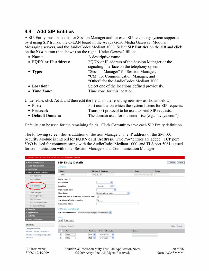
4.4 Add SIP Entities
A SIP Entity must be added for Session Manager and for each SIP telephony system supported
by it using SIP trunks: the C-LAN board in the Avaya G650 Media Gateway, Modular
Messaging servers, and the AudioCodes Mediant 1000. Select SIP Entities on the left and click
on the New button (not shown) on the right. Under General, fill in:
• Name: A descriptive name.
• FQDN or IP Address: FQDN or IP address of the Session Manager or the
signaling interface on the telephony system.
• Type: “Session Manager” for Session Manager,
“CM” for Communication Manager, and
“Other” for the AudioCodes Mediant 1000.
• Location: Select one of the locations defined previously.
• Time Zone: Time zone for this location.
Under Port, click Add, and then edit the fields in the resulting new row as shown below:
• Port: Port number on which the system listens for SIP requests.
• Protocol: Transport protocol to be used to send SIP requests.
• Default Domain: The domain used for the enterprise (e.g., “avaya.com”).
Defaults can be used for the remaining fields. Click Commit to save each SIP Entity definition.
The following screen shows addition of Session Manager. The IP address of the SM-100
Security Module is entered for FQDN or IP Address. Two Port entries are added. TCP port
5060 is used for communicating with the AudioCodes Mediant 1000, and TLS port 5061 is used
for communication with other Session Managers and Communication Manager.
FS; Reviewed:
SPOC 12/4/2009
Solution & Interoperability Test Lab Application Notes
©2009 Avaya Inc. All Rights Reserved.
21 of 58
NortelACASMMM
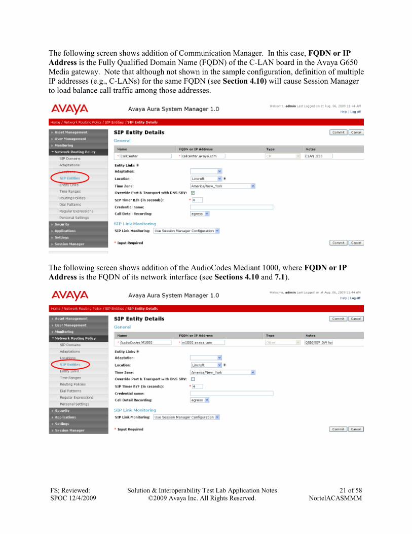
The following screen shows addition of Communication Manager. In this case, FQDN or IP
Address is the Fully Qualified Domain Name (FQDN) of the C-LAN board in the Avaya G650
Media gateway. Note that although not shown in the sample configuration, definition of multiple
IP addresses (e.g., C-LANs) for the same FQDN (see Section 4.10) will cause Session Manager
to load balance call traffic among those addresses.
The following screen shows addition of the AudioCodes Mediant 1000, where FQDN or IP
Address is the FQDN of its network interface (see Sections 4.10 and 7.1).
FS; Reviewed:
SPOC 12/4/2009
Solution & Interoperability Test Lab Application Notes
©2009 Avaya Inc. All Rights Reserved.
22 of 58
NortelACASMMM
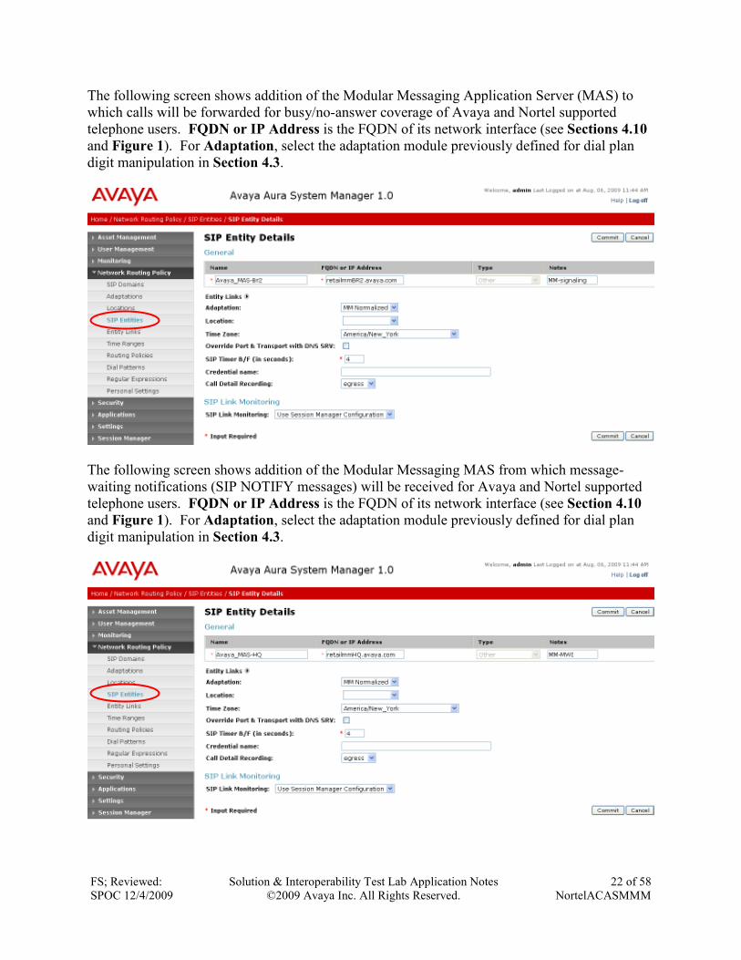
The following screen shows addition of the Modular Messaging Application Server (MAS) to
which calls will be forwarded for busy/no-answer coverage of Avaya and Nortel supported
telephone users. FQDN or IP Address is the FQDN of its network interface (see Sections 4.10
and Figure 1). For Adaptation, select the adaptation module previously defined for dial plan
digit manipulation in Section 4.3.
The following screen shows addition of the Modular Messaging MAS from which message-
waiting notifications (SIP NOTIFY messages) will be received for Avaya and Nortel supported
telephone users. FQDN or IP Address is the FQDN of its network interface (see Section 4.10
and Figure 1). For Adaptation, select the adaptation module previously defined for dial plan
digit manipulation in Section 4.3.
FS; Reviewed:
SPOC 12/4/2009
Solution & Interoperability Test Lab Application Notes
©2009 Avaya Inc. All Rights Reserved.
23 of 58
NortelACASMMM
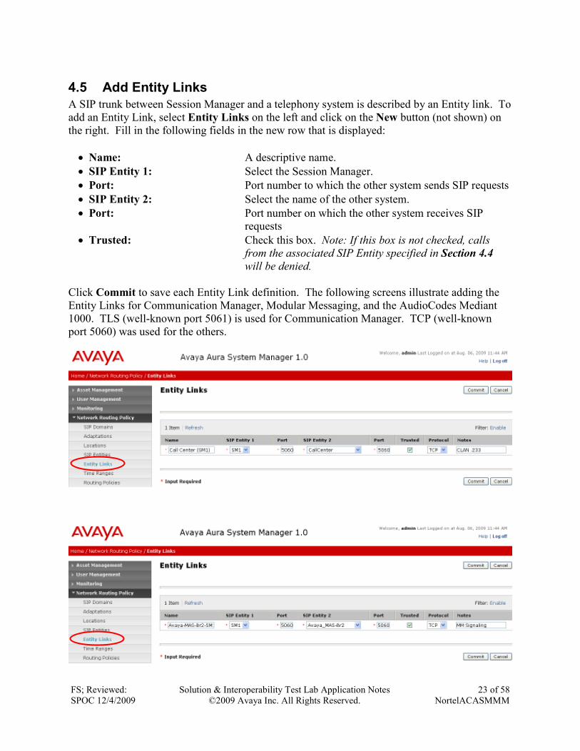
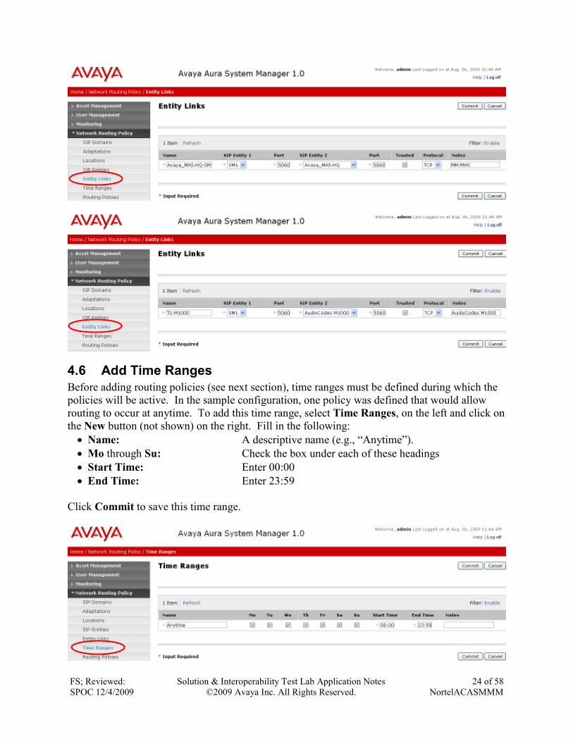
4.5 Add Entity Links
A SIP trunk between Session Manager and a telephony system is described by an Entity link. To
add an Entity Link, select Entity Links on the left and click on the New button (not shown) on
the right. Fill in the following fields in the new row that is displayed:
• Name: A descriptive name.
• SIP Entity 1: Select the Session Manager.
• Port: Port number to which the other system sends SIP requests
• SIP Entity 2: Select the name of the other system.
• Port: Port number on which the other system receives SIP
requests
• Trusted: Check this box. Note: If this box is not checked, calls
from the associated SIP Entity specified in Section 4.4
will be denied.
Click Commit to save each Entity Link definition. The following screens illustrate adding the
Entity Links for Communication Manager, Modular Messaging, and the AudioCodes Mediant
1000. TLS (well-known port 5061) is used for Communication Manager. TCP (well-known
port 5060) was used for the others.
FS; Reviewed:
SPOC 12/4/2009
Solution & Interoperability Test Lab Application Notes
©2009 Avaya Inc. All Rights Reserved.
24 of 58
NortelACASMMM
4.6 Add Time Ranges
Before adding routing policies (see next section), time ranges must be defined during which the
policies will be active. In the sample configuration, one policy was defined that would allow
routing to occur at anytime. To add this time range, select Time Ranges, on the left and click on
the New button (not shown) on the right. Fill in the following:
• Name: A descriptive name (e.g., “Anytime”).
• Mo through Su: Check the box under each of these headings
• Start Time: Enter 00:00
• End Time: Enter 23:59
Click Commit to save this time range.
FS; Reviewed:
SPOC 12/4/2009
Solution & Interoperability Test Lab Application Notes
©2009 Avaya Inc. All Rights Reserved.
25 of 58
NortelACASMMM
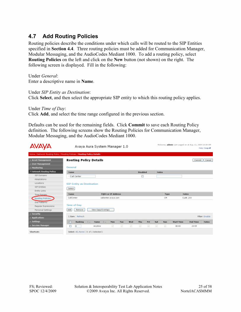
4.7 Add Routing Policies
Routing policies describe the conditions under which calls will be routed to the SIP Entities
specified in Section 4.4. Three routing policies must be added for Communication Manager,
Modular Messaging, and the AudioCodes Mediant 1000. To add a routing policy, select
Routing Policies on the left and click on the New button (not shown) on the right. The
following screen is displayed. Fill in the following:
Under General:
Enter a descriptive name in Name.
Under SIP Entity as Destination:
Click Select, and then select the appropriate SIP entity to which this routing policy applies.
Under Time of Day:
Click Add, and select the time range configured in the previous section.
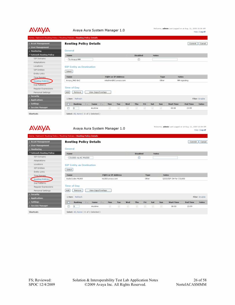
Defaults can be used for the remaining fields. Click Commit to save each Routing Policy
definition. The following screens show the Routing Policies for Communication Manager,
Modular Messaging, and the AudioCodes Mediant 1000.
FS; Reviewed:
SPOC 12/4/2009
Solution & Interoperability Test Lab Application Notes
©2009 Avaya Inc. All Rights Reserved.
26 of 58
NortelACASMMM
FS; Reviewed:
SPOC 12/4/2009
Solution & Interoperability Test Lab Application Notes
©2009 Avaya Inc. All Rights Reserved.
27 of 58
NortelACASMMM
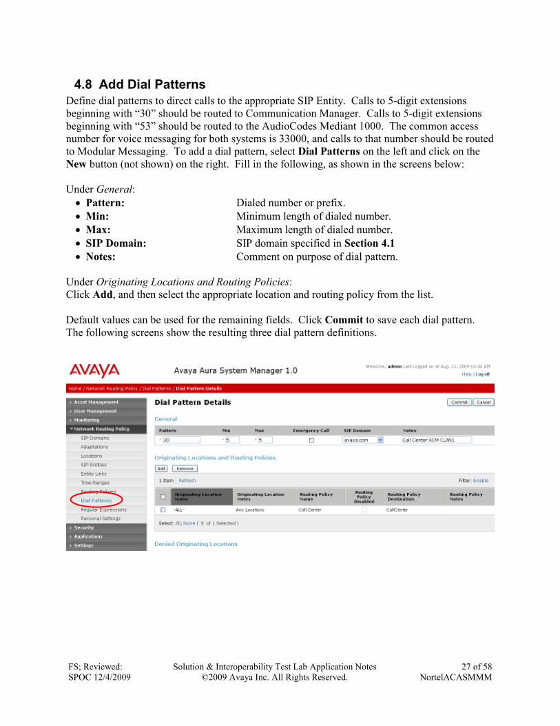
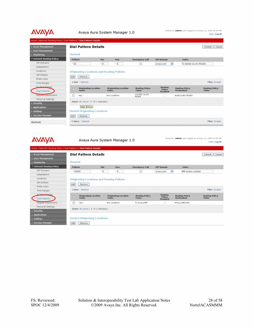
4.8 Add Dial Patterns
Define dial patterns to direct calls to the appropriate SIP Entity. Calls to 5-digit extensions
beginning with “30” should be routed to Communication Manager. Calls to 5-digit extensions
beginning with “53” should be routed to the AudioCodes Mediant 1000. The common access
number for voice messaging for both systems is 33000, and calls to that number should be routed
to Modular Messaging. To add a dial pattern, select Dial Patterns on the left and click on the
New button (not shown) on the right. Fill in the following, as shown in the screens below:
Under General:
• Pattern: Dialed number or prefix.
• Min: Minimum length of dialed number.
• Max: Maximum length of dialed number.
• SIP Domain: SIP domain specified in Section 4.1
• Notes: Comment on purpose of dial pattern.
Under Originating Locations and Routing Policies:
Click Add, and then select the appropriate location and routing policy from the list.
Default values can be used for the remaining fields. Click Commit to save each dial pattern.
The following screens show the resulting three dial pattern definitions.
FS; Reviewed:
SPOC 12/4/2009
Solution & Interoperability Test Lab Application Notes
©2009 Avaya Inc. All Rights Reserved.
28 of 58
NortelACASMMM
FS; Reviewed:
SPOC 12/4/2009
Solution & Interoperability Test Lab Application Notes
©2009 Avaya Inc. All Rights Reserved.
29 of 58
NortelACASMMM
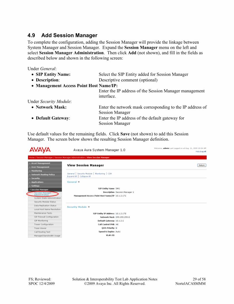
4.9 Add Session Manager
To complete the configuration, adding the Session Manager will provide the linkage between
System Manager and Session Manager. Expand the Session Manager menu on the left and
select Session Manager Administration. Then click Add (not shown), and fill in the fields as
described below and shown in the following screen:
Under General:
• SIP Entity Name: Select the SIP Entity added for Session Manager
• Description: Descriptive comment (optional)
• Management Access Point Host Name/IP:
Enter the IP address of the Session Manager management
interface.
Under Security Module:
• Network Mask: Enter the network mask corresponding to the IP address of
Session Manager
• Default Gateway: Enter the IP address of the default gateway for
Session Manager
Use default values for the remaining fields. Click Save (not shown) to add this Session
Manager. The screen below shows the resulting Session Manager definition.
FS; Reviewed:
SPOC 12/4/2009
Solution & Interoperability Test Lab Application Notes
©2009 Avaya Inc. All Rights Reserved.
30 of 58
NortelACASMMM
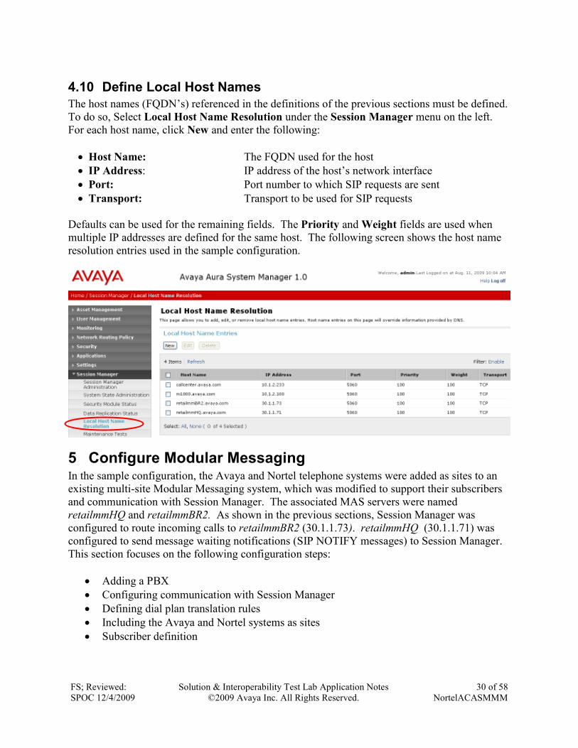
4.10 Define Local Host Names
The host names (FQDN’s) referenced in the definitions of the previous sections must be defined.
To do so, Select Local Host Name Resolution under the Session Manager menu on the left.
For each host name, click New and enter the following:
• Host Name: The FQDN used for the host
• IP Address: IP address of the host’s network interface
• Port: Port number to which SIP requests are sent
• Transport: Transport to be used for SIP requests
Defaults can be used for the remaining fields. The Priority and Weight fields are used when
multiple IP addresses are defined for the same host. The following screen shows the host name
resolution entries used in the sample configuration.
5 Configure Modular Messaging In the sample configuration, the Avaya and Nortel telephone systems were added as sites to an
existing multi-site Modular Messaging system, which was modified to support their subscribers
and communication with Session Manager. The associated MAS servers were named
retailmmHQ and retailmmBR2. As shown in the previous sections, Session Manager was
configured to route incoming calls to retailmmBR2 (30.1.1.73). retailmmHQ (30.1.1.71) was
configured to send message waiting notifications (SIP NOTIFY messages) to Session Manager.
This section focuses on the following configuration steps:
• Adding a PBX
• Configuring communication with Session Manager
• Defining dial plan translation rules
• Including the Avaya and Nortel systems as sites
• Subscriber definition
FS; Reviewed:
SPOC 12/4/2009
Solution & Interoperability Test Lab Application Notes
©2009 Avaya Inc. All Rights Reserved.
31 of 58
NortelACASMMM
See references [6-7] in Section 10 for standard installation and configuration information.
General knowledge of the configuration tools and interfaces is assumed.
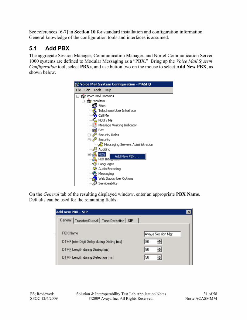
5.1 Add PBX
The aggregate Session Manager, Communication Manager, and Nortel Communication Server
1000 systems are defined to Modular Messaging as a “PBX.” Bring up the Voice Mail System
Configuration tool, select PBXs, and use button two on the mouse to select Add New PBX, as
shown below.
On the General tab of the resulting displayed window, enter an appropriate PBX Name.
Defaults can be used for the remaining fields.
FS; Reviewed:
SPOC 12/4/2009
Solution & Interoperability Test Lab Application Notes
©2009 Avaya Inc. All Rights Reserved.
32 of 58
NortelACASMMM
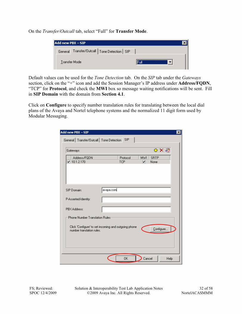
On the Transfer/Outcall tab, select “Full” for Transfer Mode.
Default values can be used for the Tone Detection tab. On the SIP tab under the Gateways
section, click on the “+” icon and add the Session Manager’s IP address under Address/FQDN,
“TCP” for Protocol, and check the MWI box so message waiting notifications will be sent. Fill
in SIP Domain with the domain from Section 4.1.
Click on Configure to specify number translation rules for translating between the local dial
plans of the Avaya and Nortel telephone systems and the normalized 11 digit form used by
Modular Messaging.
FS; Reviewed:
SPOC 12/4/2009
Solution & Interoperability Test Lab Application Notes
©2009 Avaya Inc. All Rights Reserved.
33 of 58
NortelACASMMM
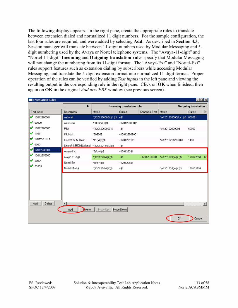
The following display appears. In the right pane, create the appropriate rules to translate
between extension dialed and normalized 11 digit numbers. For the sample configuration, the
last four rules are required, and were added by selecting Add. As described in Section 4.3,
Session manager will translate between 11-digit numbers used by Modular Messaging and 5-
digit numbering used by the Avaya or Nortel telephone systems. The “Avaya-11-digit” and
“Nortel-11-digit” Incoming and Outgoing translation rules specify that Modular Messaging
will not change the numbering from its 11-digit format. The “Avaya-Ext” and “Nortel-Ext”
rules support features such as extension dialing by subscribers while accessing Modular
Messaging, and translate the 5-digit extension format into normalized 11-digit format. Proper
operation of the rules can be verified by adding Test inputs in the left pane and viewing the
resulting output in the corresponding rule in the right pane. Click on OK when finished, then
again on OK in the original Add new PBX window (see previous screen).
FS; Reviewed:
SPOC 12/4/2009
Solution & Interoperability Test Lab Application Notes
©2009 Avaya Inc. All Rights Reserved.
34 of 58
NortelACASMMM
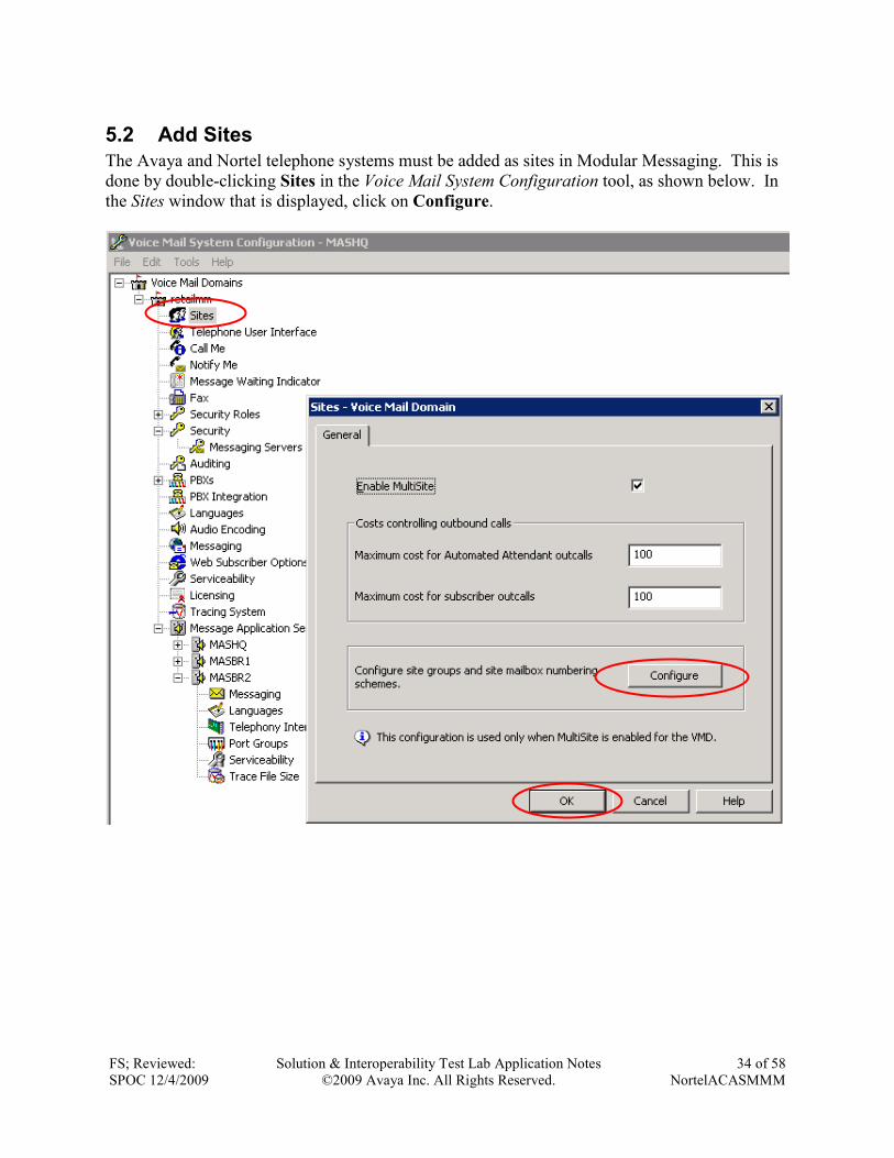
5.2 Add Sites
The Avaya and Nortel telephone systems must be added as sites in Modular Messaging. This is
done by double-clicking Sites in the Voice Mail System Configuration tool, as shown below. In
the Sites window that is displayed, click on Configure.
FS; Reviewed:
SPOC 12/4/2009
Solution & Interoperability Test Lab Application Notes
©2009 Avaya Inc. All Rights Reserved.
35 of 58
NortelACASMMM
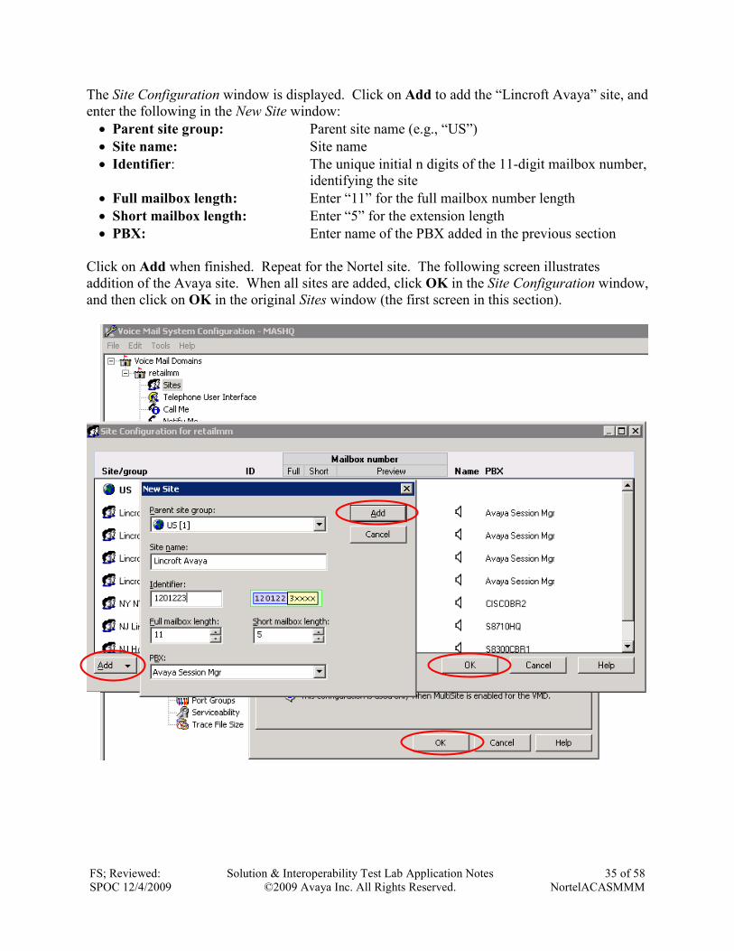
The Site Configuration window is displayed. Click on Add to add the “Lincroft Avaya” site, and
enter the following in the New Site window:
• Parent site group: Parent site name (e.g., “US”)
• Site name: Site name
• Identifier: The unique initial n digits of the 11-digit mailbox number,
identifying the site
• Full mailbox length: Enter “11” for the full mailbox number length
• Short mailbox length: Enter “5” for the extension length
• PBX: Enter name of the PBX added in the previous section
Click on Add when finished. Repeat for the Nortel site. The following screen illustrates
addition of the Avaya site. When all sites are added, click OK in the Site Configuration window,
and then click on OK in the original Sites window (the first screen in this section).
FS; Reviewed:
SPOC 12/4/2009
Solution & Interoperability Test Lab Application Notes
©2009 Avaya Inc. All Rights Reserved.
36 of 58
NortelACASMMM
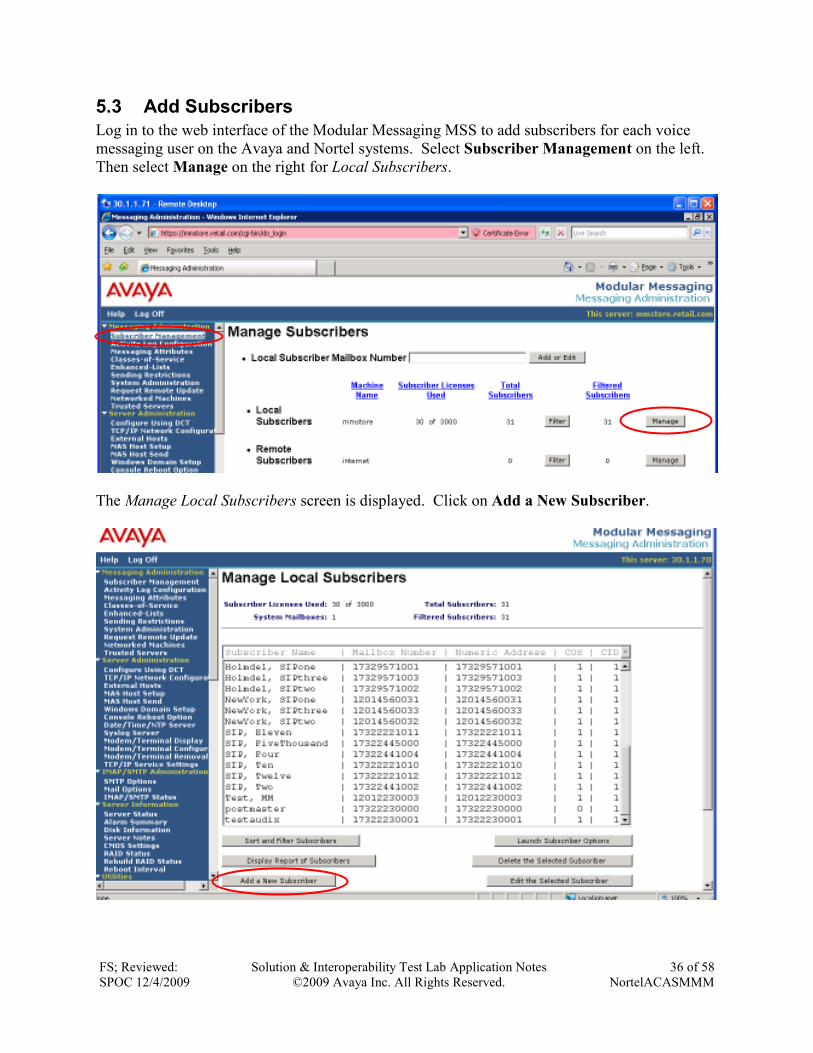
5.3 Add Subscribers
Log in to the web interface of the Modular Messaging MSS to add subscribers for each voice
messaging user on the Avaya and Nortel systems. Select Subscriber Management on the left.
Then select Manage on the right for Local Subscribers.
The Manage Local Subscribers screen is displayed. Click on Add a New Subscriber.
FS; Reviewed:
SPOC 12/4/2009
Solution & Interoperability Test Lab Application Notes
©2009 Avaya Inc. All Rights Reserved.
37 of 58
NortelACASMMM
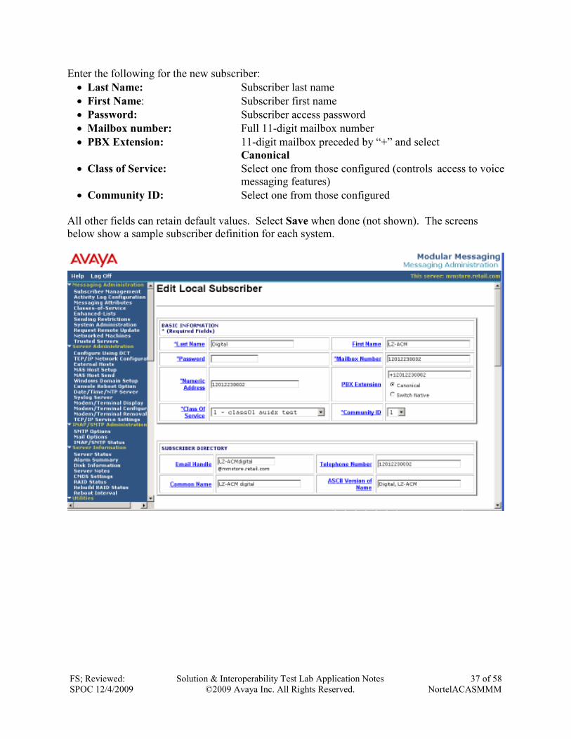
Enter the following for the new subscriber:
• Last Name: Subscriber last name
• First Name: Subscriber first name
• Password: Subscriber access password
• Mailbox number: Full 11-digit mailbox number
• PBX Extension: 11-digit mailbox preceded by “+” and select
Canonical
• Class of Service: Select one from those configured (controls access to voice
messaging features)
• Community ID: Select one from those configured
All other fields can retain default values. Select Save when done (not shown). The screens
below show a sample subscriber definition for each system.
FS; Reviewed:
SPOC 12/4/2009
Solution & Interoperability Test Lab Application Notes
©2009 Avaya Inc. All Rights Reserved.
38 of 58
NortelACASMMM
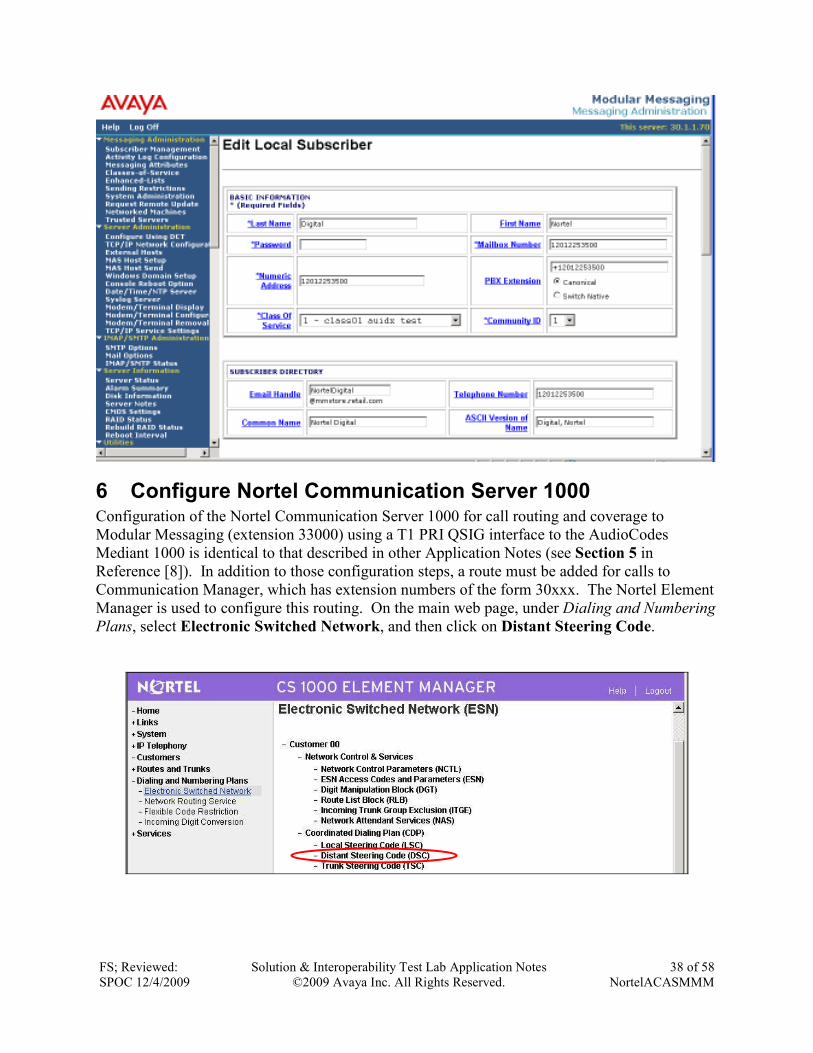
6 Configure Nortel Communication Server 1000 Configuration of the Nortel Communication Server 1000 for call routing and coverage to
Modular Messaging (extension 33000) using a T1 PRI QSIG interface to the AudioCodes
Mediant 1000 is identical to that described in other Application Notes (see Section 5 in
Reference [8]). In addition to those configuration steps, a route must be added for calls to
Communication Manager, which has extension numbers of the form 30xxx. The Nortel Element
Manager is used to configure this routing. On the main web page, under Dialing and Numbering
Plans, select Electronic Switched Network, and then click on Distant Steering Code.
FS; Reviewed:
SPOC 12/4/2009
Solution & Interoperability Test Lab Application Notes
©2009 Avaya Inc. All Rights Reserved.
39 of 58
NortelACASMMM
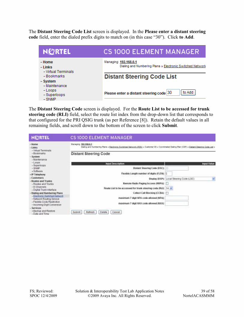
The Distant Steering Code List screen is displayed. In the Please enter a distant steering
code field, enter the dialed prefix digits to match on (in this case “30”). Click to Add.
The Distant Steering Code screen is displayed. For the Route List to be accessed for trunk
steering code (RLI) field, select the route list index from the drop-down list that corresponds to
that configured for the PRI QSIG trunk (as per Reference [8]). Retain the default values in all
remaining fields, and scroll down to the bottom of the screen to click Submit.
FS; Reviewed:
SPOC 12/4/2009
Solution & Interoperability Test Lab Application Notes
©2009 Avaya Inc. All Rights Reserved.
40 of 58
NortelACASMMM
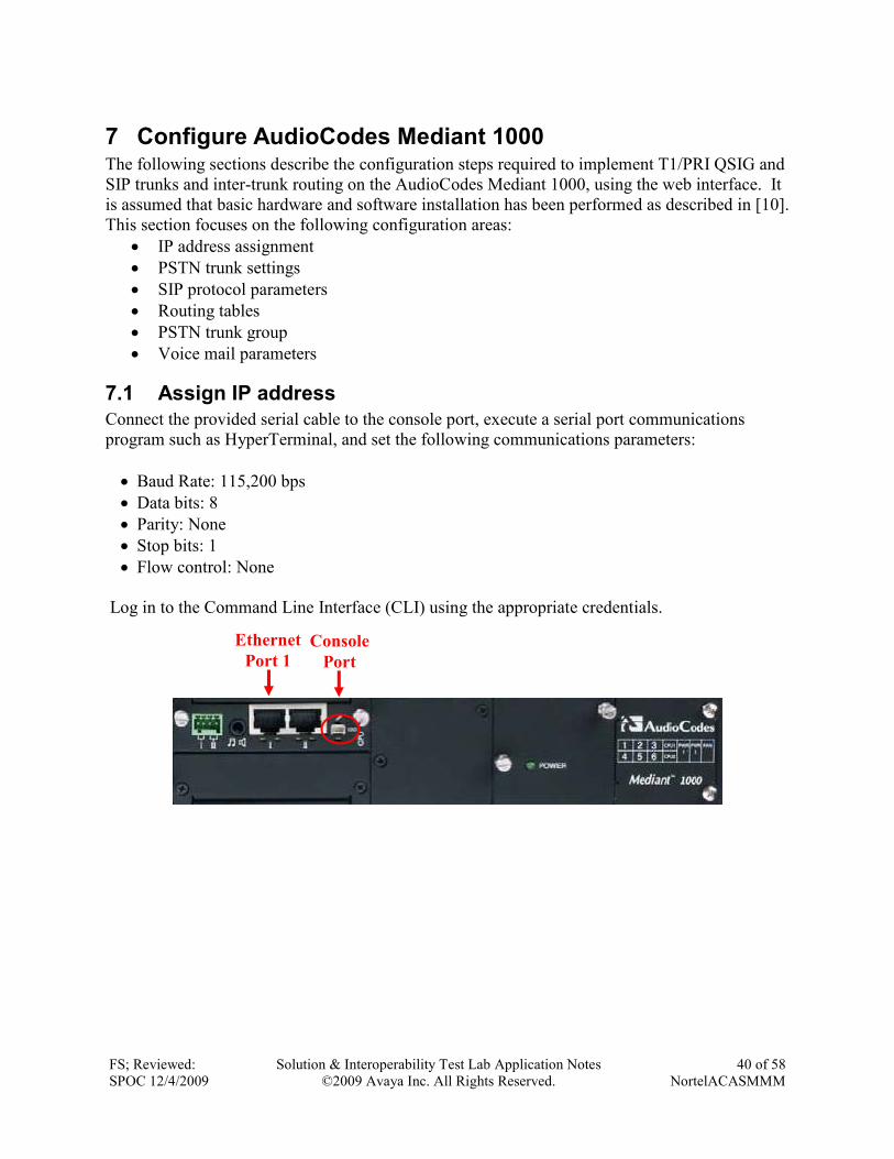
7 Configure AudioCodes Mediant 1000 The following sections describe the configuration steps required to implement T1/PRI QSIG and
SIP trunks and inter-trunk routing on the AudioCodes Mediant 1000, using the web interface. It
is assumed that basic hardware and software installation has been performed as described in [10].
This section focuses on the following configuration areas:
• IP address assignment
• PSTN trunk settings
• SIP protocol parameters
• Routing tables
• PSTN trunk group
• Voice mail parameters
7.1 Assign IP address
Connect the provided serial cable to the console port, execute a serial port communications
program such as HyperTerminal, and set the following communications parameters:
• Baud Rate: 115,200 bps
• Data bits: 8
• Parity: None
• Stop bits: 1
• Flow control: None
Log in to the Command Line Interface (CLI) using the appropriate credentials.
Ethernet
Port 1
Console
Port
FS; Reviewed:
SPOC 12/4/2009
Solution & Interoperability Test Lab Application Notes
©2009 Avaya Inc. All Rights Reserved.
41 of 58
NortelACASMMM
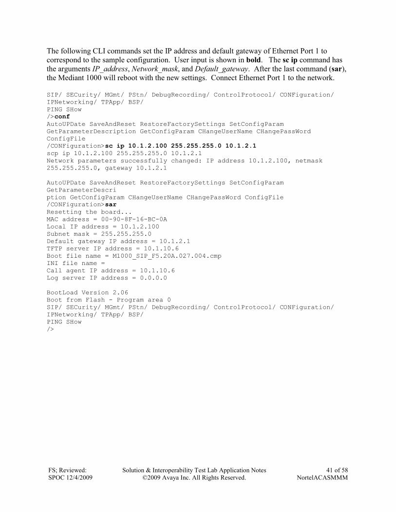
The following CLI commands set the IP address and default gateway of Ethernet Port 1 to
correspond to the sample configuration. User input is shown in bold. The sc ip command has
the arguments IP_address, Network_mask, and Default_gateway. After the last command (sar),
the Mediant 1000 will reboot with the new settings. Connect Ethernet Port 1 to the network.
SIP/ SECurity/ MGmt/ PStn/ DebugRecording/ ControlProtocol/ CONFiguration/ IPNetworking/ TPApp/ BSP/ PING SHow />conf AutoUPDate SaveAndReset RestoreFactorySettings SetConfigParam GetParameterDescription GetConfigParam CHangeUserName CHangePassWord ConfigFile /CONFiguration>sc ip 10.1.2.100 255.255.255.0 10.1.2.1 scp ip 10.1.2.100 255.255.255.0 10.1.2.1 Network parameters successfully changed: IP address 10.1.2.100, netmask 255.255.255.0, gateway 10.1.2.1 AutoUPDate SaveAndReset RestoreFactorySettings SetConfigParam GetParameterDescri ption GetConfigParam CHangeUserName CHangePassWord ConfigFile /CONFiguration>sar Resetting the board... MAC address = 00-90-8F-16-BC-0A Local IP address = 10.1.2.100 Subnet mask = 255.255.255.0 Default gateway IP address = 10.1.2.1 TFTP server IP address = 10.1.10.6 Boot file name = M1000_SIP_F5.20A.027.004.cmp INI file name = Call agent IP address = 10.1.10.6 Log server IP address = 0.0.0.0 BootLoad Version 2.06 Boot from Flash - Program area 0 SIP/ SECurity/ MGmt/ PStn/ DebugRecording/ ControlProtocol/ CONFiguration/ IPNetworking/ TPApp/ BSP/ PING SHow />
FS; Reviewed:
SPOC 12/4/2009
Solution & Interoperability Test Lab Application Notes
©2009 Avaya Inc. All Rights Reserved.
42 of 58
NortelACASMMM
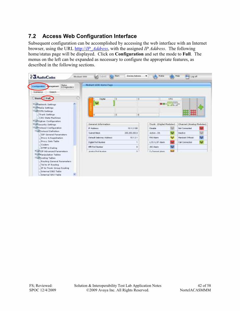
7.2 Access Web Configuration Interface
Subsequent configuration can be accomplished by accessing the web interface with an Internet
browser, using the URL http://IP_Address, with the assigned IP Address. The following
home/status page will be displayed. Click on Configuration and set the mode to Full. The
menus on the left can be expanded as necessary to configure the appropriate features, as
described in the following sections.
FS; Reviewed:
SPOC 12/4/2009
Solution & Interoperability Test Lab Application Notes
©2009 Avaya Inc. All Rights Reserved.
43 of 58
NortelACASMMM
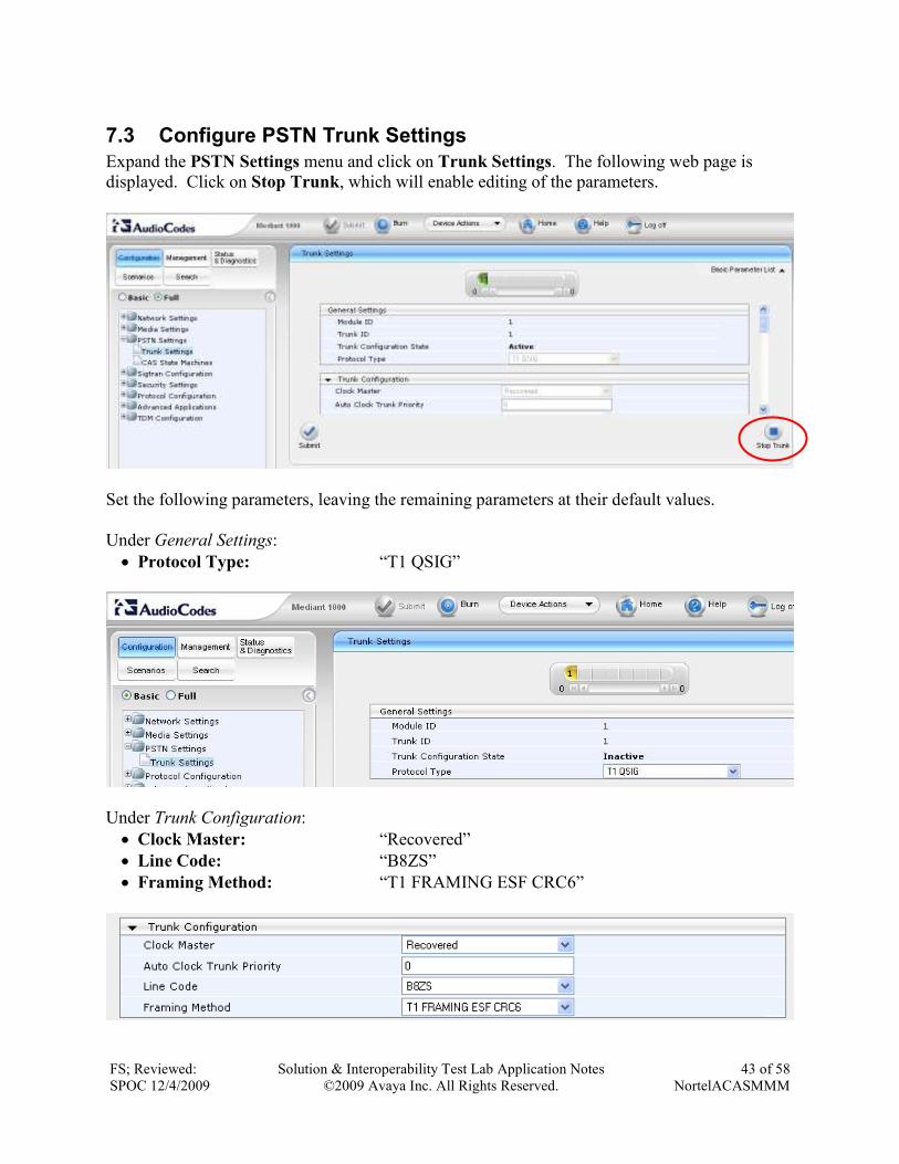
7.3 Configure PSTN Trunk Settings
Expand the PSTN Settings menu and click on Trunk Settings. The following web page is
displayed. Click on Stop Trunk, which will enable editing of the parameters.
Set the following parameters, leaving the remaining parameters at their default values.
Under General Settings:
• Protocol Type: “T1 QSIG”
Under Trunk Configuration:
• Clock Master: “Recovered”
• Line Code: “B8ZS”
• Framing Method: “T1 FRAMING ESF CRC6”
FS; Reviewed:
SPOC 12/4/2009
Solution & Interoperability Test Lab Application Notes
©2009 Avaya Inc. All Rights Reserved.
44 of 58
NortelACASMMM
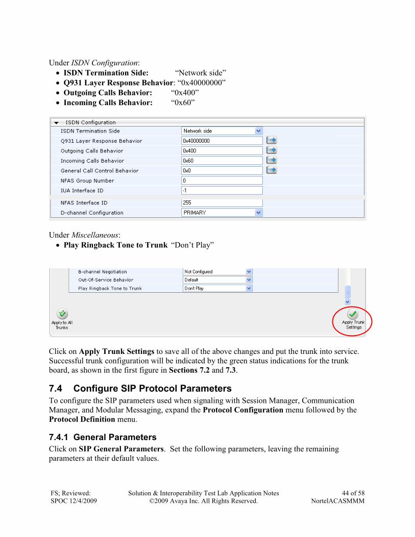
Under ISDN Configuration:
• ISDN Termination Side: “Network side”
• Q931 Layer Response Behavior: “0x40000000”
• Outgoing Calls Behavior: “0x400”
• Incoming Calls Behavior: “0x60”
Under Miscellaneous:
• Play Ringback Tone to Trunk “Don’t Play”
Click on Apply Trunk Settings to save all of the above changes and put the trunk into service.
Successful trunk configuration will be indicated by the green status indications for the trunk
board, as shown in the first figure in Sections 7.2 and 7.3.
7.4 Configure SIP Protocol Parameters
To configure the SIP parameters used when signaling with Session Manager, Communication
Manager, and Modular Messaging, expand the Protocol Configuration menu followed by the
Protocol Definition menu.
7.4.1 General Parameters
Click on SIP General Parameters. Set the following parameters, leaving the remaining
parameters at their default values.
FS; Reviewed:
SPOC 12/4/2009
Solution & Interoperability Test Lab Application Notes
©2009 Avaya Inc. All Rights Reserved.
45 of 58
NortelACASMMM
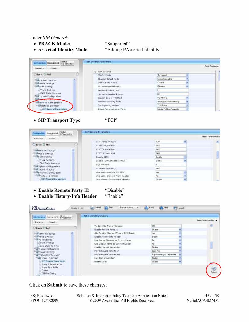
Under SIP General:
• PRACK Mode: “Supported”
• Asserted Identity Mode “Adding PAsserted Identity”
• SIP Transport Type “TCP”
• Enable Remote Party ID “Disable”
• Enable History-Info Header “Enable”
Click on Submit to save these changes.
FS; Reviewed:
SPOC 12/4/2009
Solution & Interoperability Test Lab Application Notes
©2009 Avaya Inc. All Rights Reserved.
46 of 58
NortelACASMMM
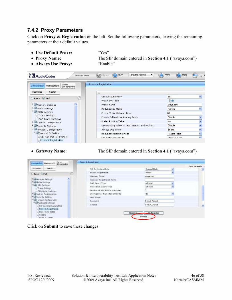
7.4.2 Proxy Parameters
Click on Proxy & Registration on the left. Set the following parameters, leaving the remaining
parameters at their default values.
• Use Default Proxy: “Yes”
• Proxy Name: The SIP domain entered in Section 4.1 (“avaya.com”)
• Always Use Proxy: “Enable”
• Gateway Name: The SIP domain entered in Section 4.1 (“avaya.com”)
Click on Submit to save these changes.
FS; Reviewed:
SPOC 12/4/2009
Solution & Interoperability Test Lab Application Notes
©2009 Avaya Inc. All Rights Reserved.
47 of 58
NortelACASMMM
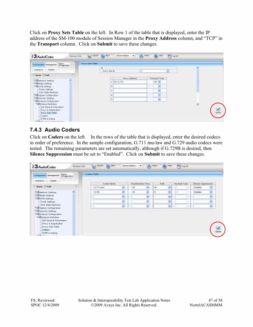
Click on Proxy Sets Table on the left. In Row 1 of the table that is displayed, enter the IP
address of the SM-100 module of Session Manager in the Proxy Address column, and “TCP” in
the Transport column. Click on Submit to save these changes.
7.4.3 Audio Coders
Click on Coders on the left. In the rows of the table that is displayed, enter the desired codecs
in order of preference. In the sample configuration, G.711 mu-law and G.729 audio codecs were
tested. The remaining parameters are set automatically, although if G.729B is desired, then
Silence Suppression must be set to “Enabled”. Click on Submit to save these changes.
FS; Reviewed:
SPOC 12/4/2009
Solution & Interoperability Test Lab Application Notes
©2009 Avaya Inc. All Rights Reserved.
48 of 58
NortelACASMMM
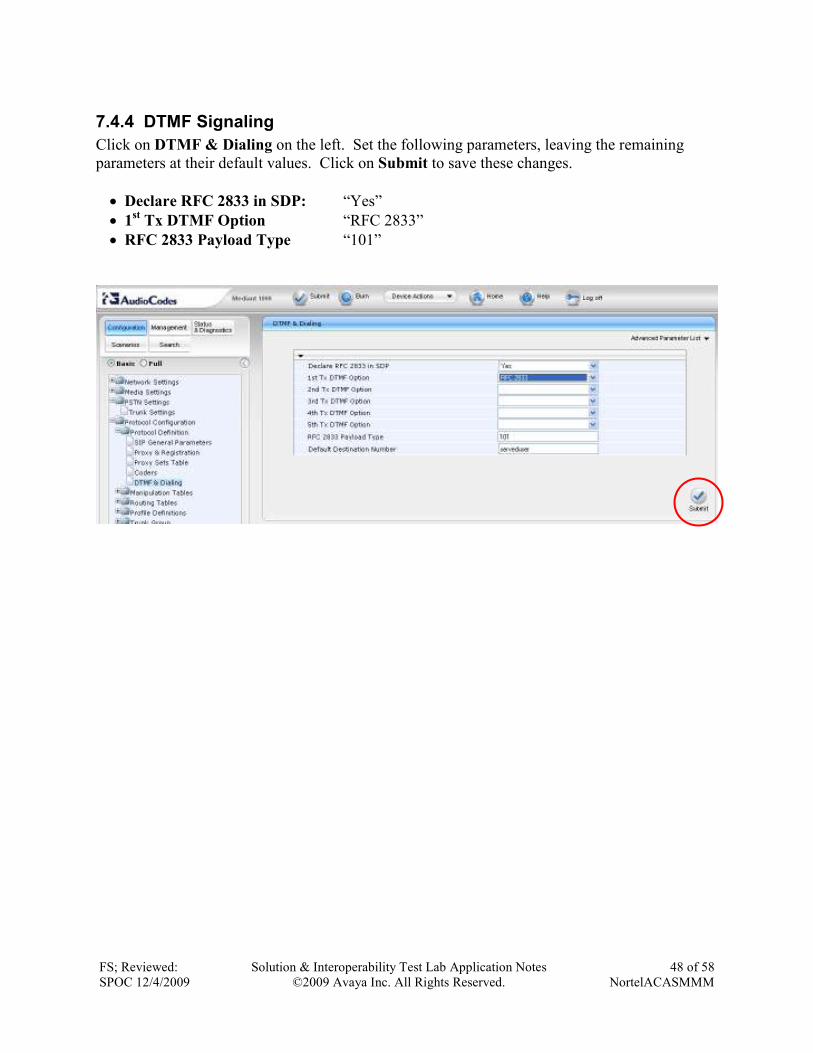
7.4.4 DTMF Signaling
Click on DTMF & Dialing on the left. Set the following parameters, leaving the remaining
parameters at their default values. Click on Submit to save these changes.
• Declare RFC 2833 in SDP: “Yes”
• 1st Tx DTMF Option “RFC 2833”
• RFC 2833 Payload Type “101”
FS; Reviewed:
SPOC 12/4/2009
Solution & Interoperability Test Lab Application Notes
©2009 Avaya Inc. All Rights Reserved.
49 of 58
NortelACASMMM
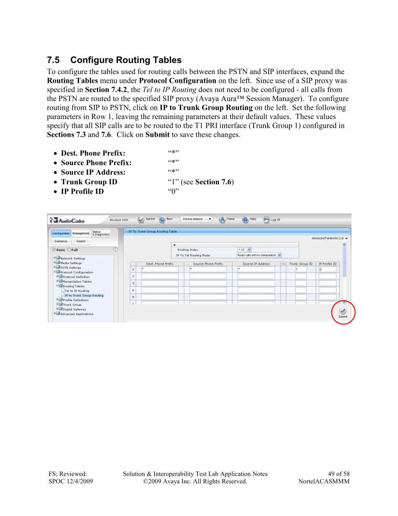
7.5 Configure Routing Tables
To configure the tables used for routing calls between the PSTN and SIP interfaces, expand the
Routing Tables menu under Protocol Configuration on the left. Since use of a SIP proxy was
specified in Section 7.4.2, the Tel to IP Routing does not need to be configured - all calls from
the PSTN are routed to the specified SIP proxy (Avaya Aura™ Session Manager). To configure
routing from SIP to PSTN, click on IP to Trunk Group Routing on the left. Set the following
parameters in Row 1, leaving the remaining parameters at their default values. These values
specify that all SIP calls are to be routed to the T1 PRI interface (Trunk Group 1) configured in
Sections 7.3 and 7.6. Click on Submit to save these changes.
• Dest. Phone Prefix: “*”
• Source Phone Prefix: “*”
• Source IP Address: “*”
• Trunk Group ID “1” (see Section 7.6)
• IP Profile ID “0”
FS; Reviewed:
SPOC 12/4/2009
Solution & Interoperability Test Lab Application Notes
©2009 Avaya Inc. All Rights Reserved.
50 of 58
NortelACASMMM
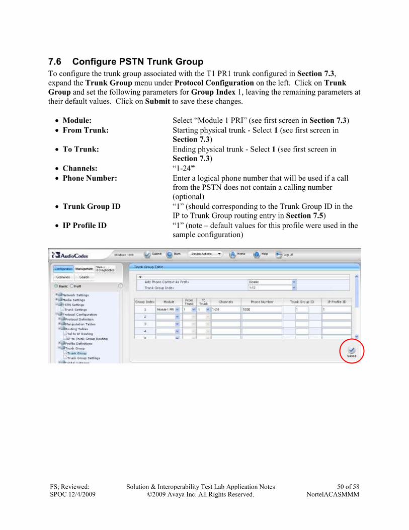
7.6 Configure PSTN Trunk Group
To configure the trunk group associated with the T1 PR1 trunk configured in Section 7.3,
expand the Trunk Group menu under Protocol Configuration on the left. Click on Trunk
Group and set the following parameters for Group Index 1, leaving the remaining parameters at
their default values. Click on Submit to save these changes.
• Module: Select “Module 1 PRI” (see first screen in Section 7.3)
• From Trunk: Starting physical trunk - Select 1 (see first screen in
Section 7.3)
• To Trunk: Ending physical trunk - Select 1 (see first screen in
Section 7.3)
• Channels: “1-24”
• Phone Number: Enter a logical phone number that will be used if a call
from the PSTN does not contain a calling number
(optional)
• Trunk Group ID “1” (should corresponding to the Trunk Group ID in the
IP to Trunk Group routing entry in Section 7.5)
• IP Profile ID “1” (note – default values for this profile were used in the
sample configuration)
FS; Reviewed:
SPOC 12/4/2009
Solution & Interoperability Test Lab Application Notes
©2009 Avaya Inc. All Rights Reserved.
51 of 58
NortelACASMMM
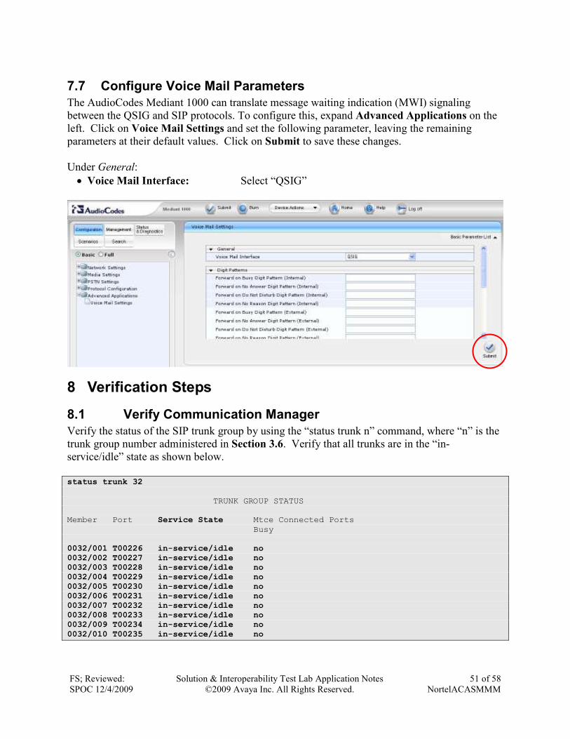
7.7 Configure Voice Mail Parameters
The AudioCodes Mediant 1000 can translate message waiting indication (MWI) signaling
between the QSIG and SIP protocols. To configure this, expand Advanced Applications on the
left. Click on Voice Mail Settings and set the following parameter, leaving the remaining
parameters at their default values. Click on Submit to save these changes.
Under General:
• Voice Mail Interface: Select “QSIG”
8 Verification Steps
8.1 Verify Communication Manager
Verify the status of the SIP trunk group by using the “status trunk n” command, where “n” is the
trunk group number administered in Section 3.6. Verify that all trunks are in the “in-
service/idle” state as shown below.
status trunk 32
TRUNK GROUP STATUS Member Port Service State Mtce Connected Ports Busy 0032/001 T00226 in-service/idle no 0032/002 T00227 in-service/idle no 0032/003 T00228 in-service/idle no 0032/004 T00229 in-service/idle no 0032/005 T00230 in-service/idle no 0032/006 T00231 in-service/idle no 0032/007 T00232 in-service/idle no 0032/008 T00233 in-service/idle no 0032/009 T00234 in-service/idle no
0032/010 T00235 in-service/idle no

FS; Reviewed:
SPOC 12/4/2009
Solution & Interoperability Test Lab Application Notes
©2009 Avaya Inc. All Rights Reserved.
52 of 58
NortelACASMMM
Verify the status of the SIP signaling groups by using the “status signaling-group n” command,
where “n” is the signaling group number administered in Section 3.6. Verify the signaling group
is “in-service” as indicated in the Group State field shown below.
status signaling-group 32
STATUS SIGNALING GROUP Group ID: 32 Active NCA-TSC Count: 0 Group Type: sip Active CA-TSC Count: 0 Signaling Type: facility associated signaling Group State: in-service
Make a call between the Avaya 9600 Series IP Telephone and the Nortel i2004 H.323
Telephone. Verify the status of connected SIP trunks by using the “status trunk x/y”, where “x”
is the number of the SIP trunk group from Section 3.6.2 to reach Session Manager, and “y” is the
member number of a connected trunk. Verify on Page 1 that the Service State is “in-
service/active”. On Page 2, verify that the IP addresses of the C-LAN and Avaya Session
Manager are shown in the Signaling section. In addition, the Audio section shows the correct
Codec Type and the IP addresses of the Avaya telephone and the AudioCodes Mediant 1000.
The Audio Connection Type displays “ip-direct”, indicating direct media between the two
endpoints.
status trunk 32/1 Page 1 of 3 TRUNK STATUS Trunk Group/Member: 0032/001 Service State: in-service/active Port: T00226 Maintenance Busy? no Signaling Group ID: 32 IGAR Connection? no Connected Ports: S00504
status trunk 32/1 Page 2 of 3 CALL CONTROL SIGNALING Near-end Signaling Loc: 01A0217 Signaling IP Address Port Near-end: 10.1.2.233 : 5060 Far-end: 10.1.2.170 : 5060
H.245 Near: H.245 Far: H.245 Signaling Loc: H.245 Tunneled in Q.931? no Audio Connection Type: ip-direct Authentication Type: None Near-end Audio Loc: Codec Type: G.711MU Audio IP Address Port Near-end: 10.1.2.253 : 6646 Far-end: 10.1.2.100 : 5200
Video Near: Video Far: Video Port: Video Near-end Codec: Video Far-end Codec:
FS; Reviewed:
SPOC 12/4/2009
Solution & Interoperability Test Lab Application Notes
©2009 Avaya Inc. All Rights Reserved.
53 of 58
NortelACASMMM
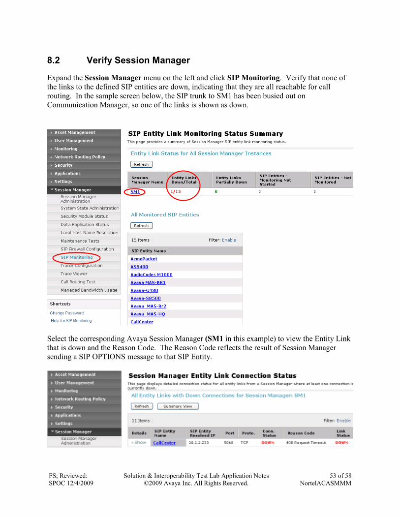
8.2 Verify Session Manager
Expand the Session Manager menu on the left and click SIP Monitoring. Verify that none of
the links to the defined SIP entities are down, indicating that they are all reachable for call
routing. In the sample screen below, the SIP trunk to SM1 has been busied out on
Communication Manager, so one of the links is shown as down.
Select the corresponding Avaya Session Manager (SM1 in this example) to view the Entity Link
that is down and the Reason Code. The Reason Code reflects the result of Session Manager
sending a SIP OPTIONS message to that SIP Entity.
FS; Reviewed:
SPOC 12/4/2009
Solution & Interoperability Test Lab Application Notes
©2009 Avaya Inc. All Rights Reserved.
54 of 58
NortelACASMMM
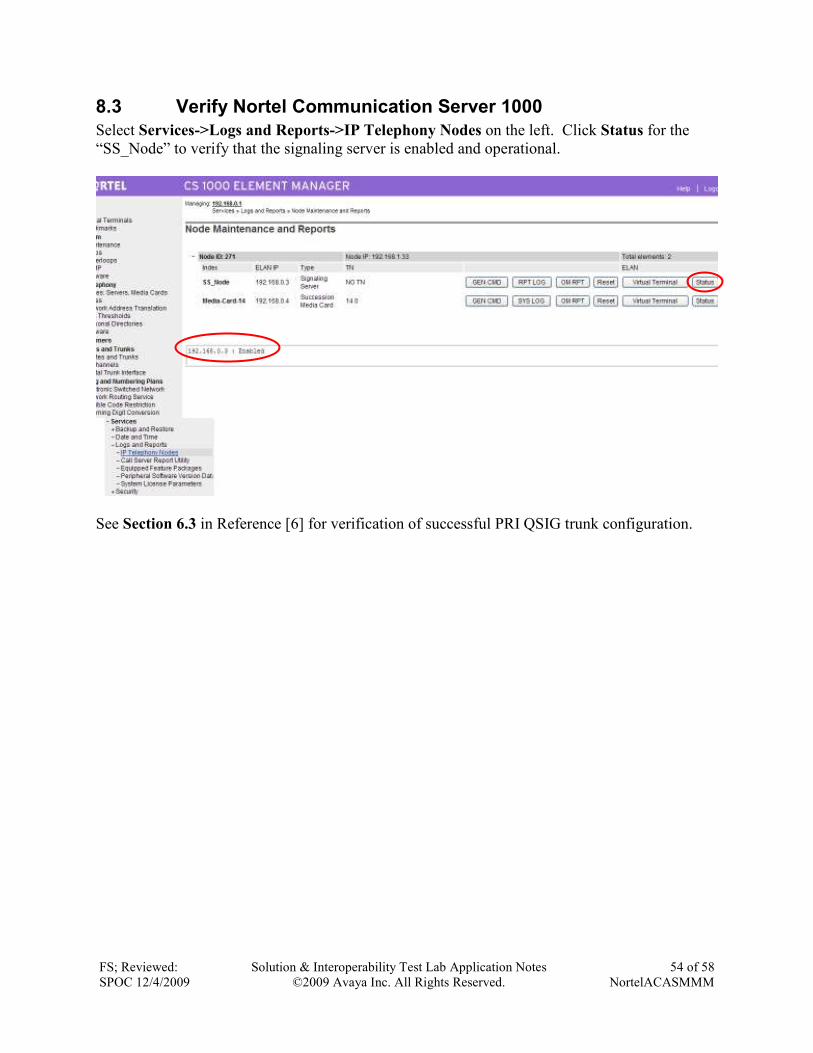
8.3 Verify Nortel Communication Server 1000
Select Services->Logs and Reports->IP Telephony Nodes on the left. Click Status for the
“SS_Node” to verify that the signaling server is enabled and operational.
See Section 6.3 in Reference [6] for verification of successful PRI QSIG trunk configuration.
FS; Reviewed:
SPOC 12/4/2009
Solution & Interoperability Test Lab Application Notes
©2009 Avaya Inc. All Rights Reserved.
55 of 58
NortelACASMMM
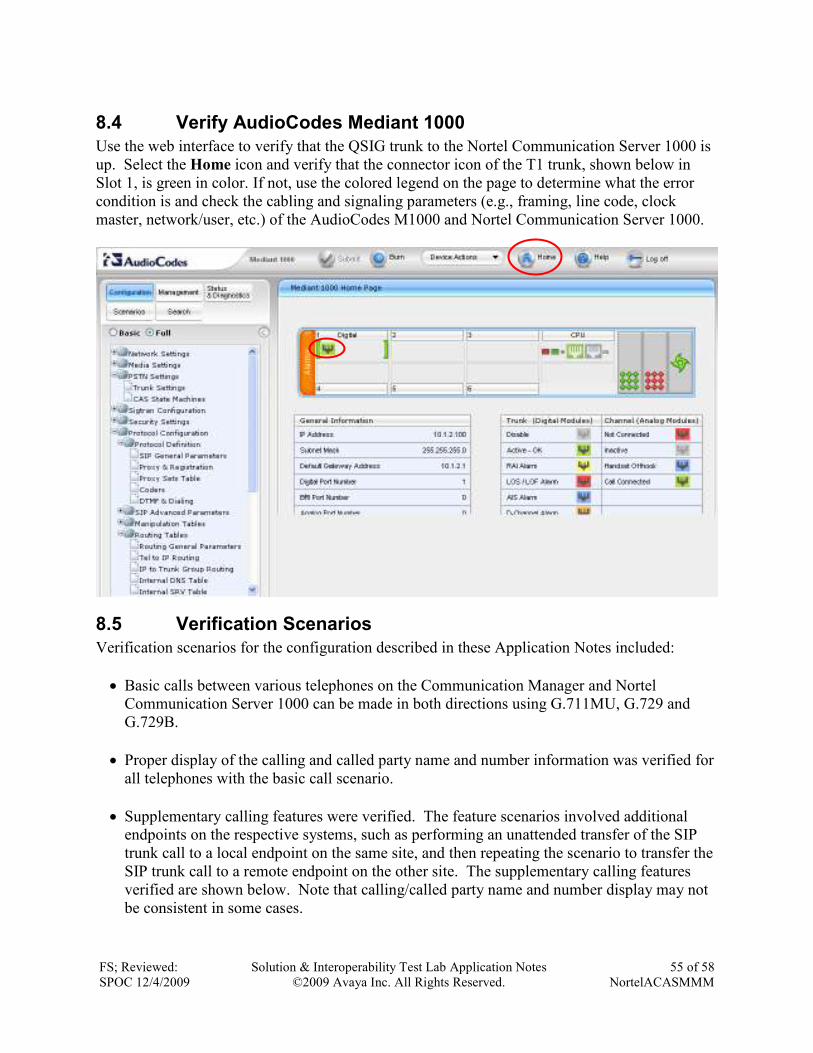
8.4 Verify AudioCodes Mediant 1000
Use the web interface to verify that the QSIG trunk to the Nortel Communication Server 1000 is
up. Select the Home icon and verify that the connector icon of the T1 trunk, shown below in
Slot 1, is green in color. If not, use the colored legend on the page to determine what the error
condition is and check the cabling and signaling parameters (e.g., framing, line code, clock
master, network/user, etc.) of the AudioCodes M1000 and Nortel Communication Server 1000.
8.5 Verification Scenarios
Verification scenarios for the configuration described in these Application Notes included:
• Basic calls between various telephones on the Communication Manager and Nortel
Communication Server 1000 can be made in both directions using G.711MU, G.729 and
G.729B.
• Proper display of the calling and called party name and number information was verified for
all telephones with the basic call scenario.
• Supplementary calling features were verified. The feature scenarios involved additional
endpoints on the respective systems, such as performing an unattended transfer of the SIP
trunk call to a local endpoint on the same site, and then repeating the scenario to transfer the
SIP trunk call to a remote endpoint on the other site. The supplementary calling features
verified are shown below. Note that calling/called party name and number display may not
be consistent in some cases.
FS; Reviewed:
SPOC 12/4/2009
Solution & Interoperability Test Lab Application Notes
©2009 Avaya Inc. All Rights Reserved.
56 of 58
NortelACASMMM
o Unattended transfer
o Attended transfer
o Hold/Unhold
o Consultation hold
o Call forwarding
o Conference
• Voice mail and voice mail calling features supported by Modular Messaging were verified,
including message waiting indicator support for the Avaya and Nortel telephones. Voice
mail calling features included:
o Busy/no answer greetings
o Message Waiting Indicator (MWI)
o Send all calls
o Coverage on call forward
o Personal operator
o Auto-attendant
o Find me
o Call me
o Call sender
o Transfer
9 Conclusion As illustrated in these Application Notes, Nortel Communication Server 1000 front-ended by the
AudioCodes Mediant 1000 can be integrated with Avaya SIP products, including Avaya Aura™
Session Manager, Avaya Aura™ Communication Manager 5.2, and Avaya Modular Messaging.
The following is a list of interoperability items to note:
• Calling/called party name and number display may not be consistent for some calling
features.
• The following voice mail scenarios are not supported:
o Voice mail coverage for calls to an Avaya subscriber with calls forwarded to a
Nortel subscriber
o An Avaya subscriber as personal operator for a Nortel subscriber
o An Avaya subscriber as a find-me destination for a Nortel subscriber
FS; Reviewed:
SPOC 12/4/2009
Solution & Interoperability Test Lab Application Notes
©2009 Avaya Inc. All Rights Reserved.
57 of 58
NortelACASMMM
10 Additional References This section references the product documentation relevant to these Application Notes.
Avaya Aura™ Session Manager:
[1] Avaya Aura™ Session Manager Overview, Doc ID 03-603323, available at
http://support.avaya.com.
[2] Installing and Administering Avaya Aura™ Session Manager, Doc ID 03-603324,
available at http://support.avaya.com.
[3] Maintaining and Troubleshooting Avaya Aura™ Session Manager, Doc ID 03-603325,
available at http://support.avaya.com.
Avaya Aura™ Communication Manager 5.2:
[4] SIP Support in Avaya Aura™ Communication Manager Running on Avaya S8xxx
Servers, Doc ID 555-245-206, May, 2009, available at http://support.avaya.com.
[5] Administering Avaya Aura™ Communication Manager, Doc ID 03-300509, May 2009,
available at http://support.avaya.com.
Avaya Modular Messaging:
[6] Release 5.1 with Avaya MSS – Messaging Application Server (MAS) Administration
Guide, June, 2009, available at http://support.avaya.com.
[7] Avaya Modular Messaging for theAvaya Message Storage Server (MSS) Configuration –
Release 5.1 Installation and Upgrades, June, 2009, available at http://support.avaya.com.
Avaya Application Notes:
[8] Configure an Avaya Centralized Messaging Solution with Avaya Communication
Manager and Nortel Communication Server 1000 – Issue 1.0, available at
http://www.avaya.com.
[9] Configuring SIP Trunks among Avaya Aura™ Session Manager, Avaya Aura™
Communication Manager 5.2, and Nortel Communication Server 1000 – Issue 1.1,
available at http://www.avaya.com.
AudioCodes Mediant 1000:
[10] Mediant 1000 MSBG Installation Manual (SIP) Version 5.6, available at
http://www.audiocodes.com.
FS; Reviewed:
SPOC 12/4/2009
Solution & Interoperability Test Lab Application Notes
©2009 Avaya Inc. All Rights Reserved.
58 of 58
NortelACASMMM
©2009 Avaya Inc. All Rights Reserved.
Avaya and the Avaya Logo are trademarks of Avaya Inc. All trademarks identified by ® and ™
are registered trademarks or trademarks, respectively, of Avaya Inc. All other trademarks are the
property of their respective owners. The information provided in these Application Notes is
subject to change without notice. The configurations, technical data, and recommendations
provided in these Application Notes are believed to be accurate and dependable, but are
presented without express or implied warranty. Users are responsible for their application of any
products specified in these Application Notes.
Please e-mail any questions or comments pertaining to these Application Notes along with the
full title name and filename, located in the lower right corner, directly to the Avaya Solution &
Interoperability Test Lab at [email protected]