Embed Size (px)
Citation preview
I500 (i5MT, i5MR, i5MQ)
Manual
I500
iSTAT Enhanced 3ph Transducer
Publication Reference: I500/EN/M/F
I500/EN/M/F © 2014. ALSTOM, the ALSTOM logo and any alternative version thereof are trademarks and service marks of ALSTOM. The other names mentioned,
registered or not, are the property of their respective companies. The technical and other data contained in this document is provided for information only. Neither
ALSTOM, its officers or employees accept responsibility for, or should be taken as making any representation or warranty (whether express or implied), as to the
accuracy or completeness of such data or the achievement of any projected performance criteria where these are indicated. ALSTOM reserves the right to revise or
change this data at any time without further notice.
GRID

User Manual I500/EN M/F iSTAT I500 3ph Multifunction
Page 1
1. SAFETY SECTION
This Safety Section should be read before commencing any work on the equipment.
1.1 Health and Safety
The information in the Safety Section of the product documentation is intended to ensure that products are properly installed and handled in order to maintain them in a safe condition. It is assumed that everyone who will be associated with the equipment will be familiar with the contents of the Safety Section.
1.2 Explanation of symbols and labels
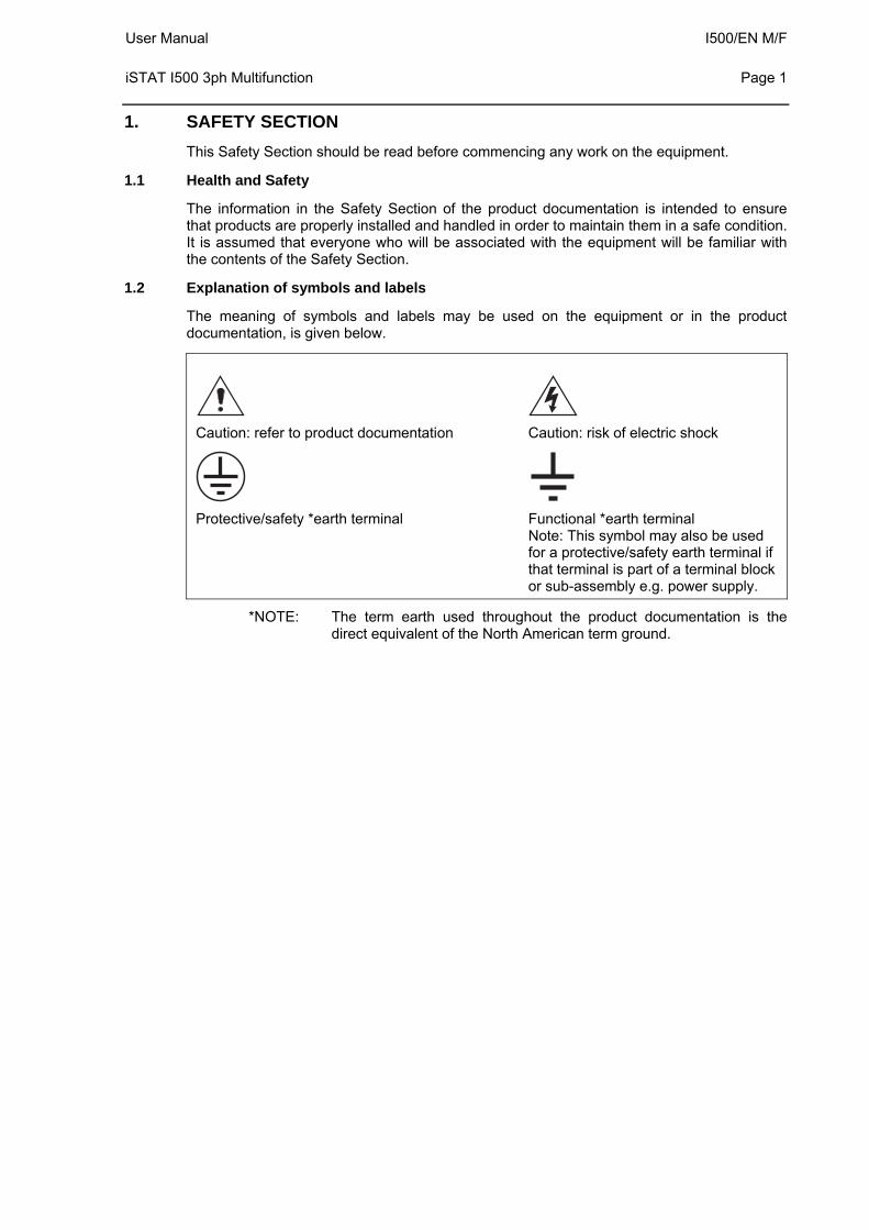
The meaning of symbols and labels may be used on the equipment or in the product documentation, is given below.
Caution: refer to product documentation Caution: risk of electric shock
Protective/safety *earth terminal Functional *earth terminal Note: This symbol may also be used for a protective/safety earth terminal if that terminal is part of a terminal block or sub-assembly e.g. power supply.
*NOTE: The term earth used throughout the product documentation is the direct equivalent of the North American term ground.
I500/EN M/F User Manual Page 2
iSTAT I500 3ph Multifunction
2. INSTALLING, COMMISSIONING AND SERVICING
Equipment connections
Personnel undertaking installation, commissioning or servicing work on this equipment should be aware of the correct working procedures to ensure safety. The product documentation should be consulted before installing, commissioning or servicing the equipment.
Terminals exposed during installation, commissioning and maintenance may present a hazardous voltage unless the equipment is electrically isolated.
If there is unlocked access to the rear of the equipment, care should be taken by all personnel to avoid electrical shock or energy hazards.
Voltage and current connections should be made using insulated crimp terminations to ensure that terminal block insulation requirements are maintained for safety. To ensure that wires are correctly terminated the correct crimp terminal and tool for the wire size should be used.
Before energising the equipment it must be earthed using the protective earth terminal, or the appropriate termination of the supply plug in the case of plug connected equipment. Omitting or disconnecting the equipment earth may cause a safety hazard.
The recommended minimum earth wire size is 2.5mm2, unless otherwise stated in the technical data section of the product documentation.
Before energising the equipment, the following should be checked:
Voltage rating, frequency and polarity
VT ratio and phase sequence
CT circuit rating and integrity of connections;
Protective fuse rating;
Integrity of earth connection (where applicable)
Supply voltage
User Manual I500/EN M/F iSTAT I500 3ph Multifunction
Page 3
3. EQUIPMENT OPERATING CONDITIONS
The equipment should be operated within the specified electrical and environmental limits.
3.1 Current transformer circuits
Do not open the secondary circuit of a live CT since the high level voltage produced may be lethal to personnel and could damage insulation.
3.2 Battery Replacement
Where internal batteries are fitted they should be replaced with the recommended type and be installed with the correct polarity, to avoid possible damage to the equipment.
3.3 Insulation and dielectric strength testing
Insulation testing may leave capacitors charged up to a hazardous voltage. At the end of each part of the test, the voltage should be gradually reduced to zero, to discharge capacitors, before the test leads are disconnected.
3.4 Opening enclosure
There are no customer replaceable PCB cards or components within the enclosure, so the enclosure should not be opened.
4. DECOMMISSIONING AND DISPOSAL
Decommissioning: The auxiliary supply circuit in the relay may include capacitors across the supply or to earth. To avoid electric shock or energy hazards, after completely isolating the supplies to the relay (both poles of any dc supply), the capacitors should be safely discharged via the external terminals prior to decommissioning.
Disposal: It is recommended that incineration and disposal to water courses is avoided. The product should be disposed of in a safe manner. Any products containing batteries should have them removed before disposal, taking precautions to avoid short circuits. Particular regulations within the country of operation, may apply to the disposal of lithium batteries.
I500/EN M/F User Manual Page 4
iSTAT I500 3ph Multifunction
5. TECHNICAL SPECIFICATIONS
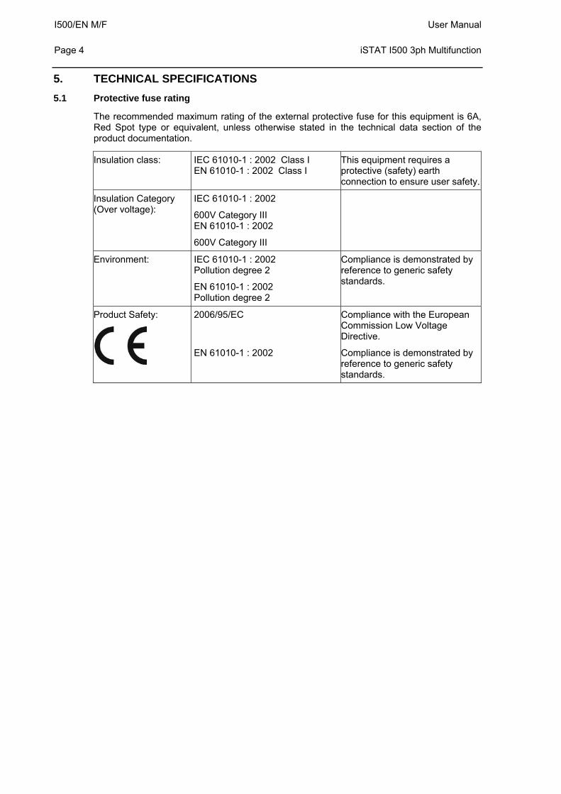
5.1 Protective fuse rating
The recommended maximum rating of the external protective fuse for this equipment is 6A, Red Spot type or equivalent, unless otherwise stated in the technical data section of the product documentation.
Insulation class: IEC 61010-1 : 2002 Class I EN 61010-1 : 2002 Class I
This equipment requires a protective (safety) earth connection to ensure user safety.
Insulation Category (Over voltage):
IEC 61010-1 : 2002
600V Category III EN 61010-1 : 2002
600V Category III
Environment: IEC 61010-1 : 2002 Pollution degree 2
EN 61010-1 : 2002 Pollution degree 2
Compliance is demonstrated by reference to generic safety standards.
Product Safety:
2006/95/EC
EN 61010-1 : 2002
Compliance with the European Commission Low Voltage Directive.
Compliance is demonstrated by reference to generic safety standards.
User Manual I500/EN M/F iSTAT I500 3ph Multifunction
Page 5
CONTENT
1. 1 SAFETY SECTION
1.1 1 Health and Safety
1.2 1 Explanation of symbols and labels
2. 2 INSTALLING, COMMISSIONING AND SERVICING
3. 3 EQUIPMENT OPERATING CONDITIONS
3.1 3 Current transformer circuits
3.2 3 Battery Replacement
3.3 3 Insulation and dielectric strength testing
3.4 3 Opening enclosure
4. 3 DECOMMISSIONING AND DISPOSAL
5. 4 TECHNICAL SPECIFICATIONS
5.1 4 Protective fuse rating
6. 11 INTRODUCTION
6.1 11 General
6.2 11 KEY MESSAGES
6.3 12 iSTAT I500 Family
6.3.1 12 i5MT class 0.2 multifunction communicating Transducer.
6.3.2 12 i5MR class 0.2 communicating Network Recorder
6.3.3 12 i5MQ class 0.2 communicating Network Analyser.
6.3.4 13 Remote display i5RD
6.3.5 13 Software:
6.4 13 Measurements
6.5 14 Hardware features
6.6 14 Communications
6.7 15 Inputs and Outputs
6.8 15 Applications
7. 17 HARDWARE
7.1 17 Communications
7.1.1 17 RS232 /RS485 communications
7.1.2 18 Ethernet and USB communications
7.1.3 19 Communication connection details
7.2 20 Inputs and Outputs
I500/EN M/F User Manual Page 6
iSTAT I500 3ph Multifunction
7.2.1 20 Energy Contacts (Pulse outputs)
7.2.2 21 Tariff (inputs)
7.2.3 21 Alarm (outputs)
7.2.4 22 Analogue (outputs)
7.2.5 22 Digital Input
7.2.6 22 Watchdog Output
7.2.7 23 Analogue Input
7.2.8 23 Pulse Input
7.2.9 23 COM2 RS485 port
7.3 24 Auxiliary Supply
7.4 24 Measurement Inputs
8. 25 SETTINGS
8.1 25 Introduction
8.2 25 QDSP Software
8.2.1 25 Devices Management
8.2.2 25 Instrument settings
8.2.3 25 Real time measurements
8.2.4 25 Data Analysis
8.2.5 25 Software upgrading
8.3 26 Setting Procedure
8.4 26 General Settings
8.4.1 26 Description and Location
8.4.2 26 Average Interval
8.4.3 27 Currency (RD)
8.4.4 27 Temperature unit (RD)
8.4.5 27 Date Format (RD)
8.4.6 27 Date and Time (RD)
8.4.7 27 Auto Summer/Winter time (RD)
8.4.8 27 Maximum Demand calculation (MD mode) (RD)
8.4.9 27 Resetting Min/Max (RD)
8.4.10 27 Starting Current for PF and PA (mA)
8.4.11 28 Starting current for all powers (mA)
8.4.12 28 Calculation of Harmonics
8.4.13 28 Reactive power calculation
8.5 28 Connection
8.5.1 29 Connection (RD)
8.5.2 29 Setting of current and voltage ratios (RD)
8.5.3 29 Used Voltage and Current Range
8.5.4 30 Nominal Frequency
8.6 30 Communication
User Manual I500/EN M/F iSTAT I500 3ph Multifunction
Page 7
8.6.1 30 Serial Communication parameters (COM1) (RD)
8.6.2 30 Ethernet Communication
8.6.3 30 USB
8.7 31 Security
8.7.1 31 Password setting (RD)
8.7.2 31 Password modification (RD)
8.8 31 Energy
8.8.1 32 Active Tariff (RD)
8.8.2 32 Common Energy Exponent
8.8.3 32 Common exponent of energy cost
8.8.4 32 Common exponent of tariff price and energy price in tariffs
8.8.5 32 Measured Energy
8.8.6 33 Counter Divider
8.8.7 33 Tariff selector
8.8.8 34 Tariff Clock
8.9 36 Inputs and Outputs
8.9.1 36 Analogue output module
8.9.2 37 Alarm/Digital Output Module (RD)
8.9.3 37 Pulse Output Module (RD)
8.9.4 37 Tariff input module
8.9.5 38 Digital Input module
8.9.6 38 Watchdog Output module
8.9.7 38 Analogue Input module
8.9.8 38 Pulse Input module
8.9.9 38 2 Communications module (COM2) (RD)nd
8.10 39 Alarms
8.10.1 39 Alarm setting
8.10.2 39 Types of Alarm
8.11 40 Memory
8.11.1 41 Memory division
8.11.2 41 Memory clearing
8.12 41 Data Recorders
8.12.1 41 Storage interval
8.12.2 42 MD Time constant
8.12.3 42 Recorded quantities
8.13 42 Power Quality Recorder Report
I500/EN M/F User Manual Page 8
iSTAT I500 3ph Multifunction
8.13.1 43 Power Supply Quality
8.13.2 44 Frequency Variations
8.13.3 44 Voltage Variations
8.13.4 44 Dips and Interruptions
8.13.5 44 Rapid Voltage Changes
8.13.6 44 Temporary overvoltages, flickers.
8.13.7 44 Harmonics and THD
8.13.8 44 Reseting quality parameter reports
8.14 44 Reset Operations
8.14.1 44 Reset Min/Max values (RD)
8.14.2 44 Set energy counters (RD)
8.14.3 44 Reset Energy counter costs (RD)
8.14.4 44 Reset maximal MD values (RD)
8.14.5 45 Reset the last MD period (RD)
8.14.6 45 MD synchronization (RD)
8.14.7 45 Reset alarm output (RD)
9. 46 SYSTEM MODES
9.1 46 Connection mode
9.1.1 46 Valid measurements
9.2 50 Power mode
9.3 50 Operating energy quadrants
10. 51 INSTRUMENTATION
10.1 51 Measurements
10.2 51 Glossary
10.3 53 Supported Measurements
10.3.1 55 Voltage
10.3.2 56 Current
10.3.3 56 Angles between Phases
10.3.4 56 Frequency
10.3.5 57 Harmonics
10.4 58 Power, power factor and energy
10.4.1 58 Power
10.4.2 60 Power factor
10.4.3 60 Energy
10.4.4 60 Real time clock (energy clock)
10.4.5 60 Maximum demands (MDs)
10.4.6 60 Average demands
10.5 63 Power Quality
User Manual I500/EN M/F iSTAT I500 3ph Multifunction
Page 9
10.5.1 63 Frequency and Voltage variations
10.5.2 63 Voltage Interruptions and dips
10.5.3 63 Fast Voltage changes
10.5.4 63 Flicker – short term
10.5.5 63 Flicker – long term
11. 64 COMMUNICATIONS
11.1 64 Communications ports
11.2 64 QDSP Setting and Monitoring Software
11.3 64 MODBUS
11.4 64 DNP3
12. 65 BATTERY REPLACEMENT
13. 66 REMOTE DISPLAY FEATURES
13.1 66 Hardware
13.2 66 Programming i500
13.3 67 Remote display settings
13.3.1 67 General settings
13.4 68 Remote mode
13.4.1 68 Entering to remote mode
13.4.2 68 Displaying device information’s
13.4.3 69 Installation wizard
13.4.4 69 Device settings
13.4.5 70 Exiting from remote mode
14. 71 TECHNICAL DATA
15. 78 WIRING DIAGRAMS
16. 84 RELATED DOCUMENTS

I500/EN M/F User Manual Page 10
iSTAT I500 3ph Multifunction
BLANK PAGE
User Manual I500/EN M/F iSTAT I500 3ph Multifunction
Page 11
6. INTRODUCTION
6.1 General
The I500 is a multifunction transducer family aimed at the high and medium voltage and industrial market segments throughout the world. It allows the user to select the most appropriate model from the family and customise the features to suit the particular application.
The I500 multifunction transducer family integrates a number of measurements, monitoring, recording and metering functions in the same unit for comprehensive power system management. The I500 offers:
High accuracy measurements
A cost-effective solution for High, Medium Voltage and Industrial markets
Power Quality analysis to EN50160
Modbus protocol for integrating into energy management and control systems.
Tariff and cost management functions for use in sub metering applications.
Digital inputs and outputs and analogue inputs and outputs
CE certification
6.2 KEY MESSAGES
The iSTAT I500 provides Class 0.2 measurement of Volts, Current and Power and Class 0.5S for Energy measurement.
The iSTAT I500 is an economical choice for measurements, with a family that allows the user to tailor the transducer and functions to the application.
The comprehensive Energy Cost Management Library of functions enables the I500 to store energy readings in 4 registers and programme tariff structures and costs. This data can be recorded, communicated or read via pulse outputs
I500 offers multiple communication hardware options to allow integration in to a wide range of applications.
I500 allows communication to MODBUS based systems that are widely used by industrial and utility customers worldwide.
I500 is available with either Ring or Pin terminals to suit the installation requirements.
iSTAT – THE standard measurement platform
Multiple advanced configuration features fitted as standard.
Comprehensive choice of features for measurement applications – to satisfy all metering, measurement and data recording and power quality applications
Flexible programmable software (QDSP) allows off line and on line settings and data interpretation
Complete and informative documentation, QDSP also includes help information.
A choice of different input and output options.
Simple to fit, simple to set, simple to connect
I500/EN M/F User Manual Page 12
iSTAT I500 3ph Multifunction
6.3 iSTAT I500 Family
The I500 family consists of 3-phase and single phase transducers all of which are 0.2% multifunction instruments. This manual details the 3-phase transducer models and the Remote Display that can be connected to them.
6.3.1 i5MT class 0.2 multifunction communicating Transducer.
The transducer is used for monitoring and measuring electric quantities of single or three-phase electrical power distribution systems. The meter is provided with 32 program adjustable alarms, up to four input or output modules and communication. With the RS232/RS485, Ethernet or USB communication, the meter can be set and measurements can be checked.
The meter also functions as an energy counter, with the additional function of cost management by tariffs. A tariff input or a tariff clock can be set. When using tariff clock setting, four seasons and four day groups as well as energy cost for each period and a day group (16 different cost periods) are available. Additionally, the instrument can store up to 20 holidays. As an energy counter it can record energy in four tariffs in all four quadrants of the load power diagram.
The i5MT can be used as a
Power Meter for monitoring and measuring electrical parameters in a power system.
Class 0.5S Energy Meter with measurement in all 4 quadrants, suitable for secondary-metering applications (not revenue metering).
6.3.2 i5MR class 0.2 communicating Network Recorder
The transducer is used for monitoring, measuring and recording measurements of electric quantities of electrical power distribution systems. The i5MR measures all the same parameters as the i5MT and up to 64 measurements and up to 32 alarms can be recorded in the internal 8MB memory. The memory is separated into up to 4 sections for measurements and one section for recording alarms. The memory division is defined by the user via communication.
6.3.3 i5MQ class 0.2 communicating Network Analyser.
The transducer measures all the same parameters and includes the data logger as in the i5MR, and is used also for permanent analysis of electricity supply quality in compliance with the EN 50160 standard. A partition in the internal memory is reserved for storing reports for a period of the last seven years. The internal memory capacity enables storing of more than 170,000 variations of the measurements from the standard values, which enables fault analysis for problems in the network. Limits and required quality in a monitored period can be defined for each monitored characteristic. The following characteristics are measured and recorded:
Frequency variations
Voltage variations
Voltage unbalances
Voltage dips
Voltage interruptions
Rapid voltage changes
Flickers Pst & Plt
Temporary overvoltage’s
THD's
Harmonics
User Manual I500/EN M/F iSTAT I500 3ph Multifunction
Page 13
6.3.4 Remote display i5RD
The transducers can be connected to the i5RD Remote display, with up to 31 transducers connected to a single display. The Remote display is very useful for a quick look-up to all measured parameters or to set up the I500 measuring transducers without the PC. A graphical display with the resolution of 128x64 enables graphical representation of signals and parameters. With five select buttons it is possible to browse through the user-friendly menu.
6.3.5 Software:
The same QDSP software is used for configuring the devices as on all iSTAT communicating products.
The QDSP software is used for configuration and to browse the measurement values. In addition it is used to configure the data recorders and Power Quality analyser and to download and analyse the data stored.
6.4 Measurements
The I500 family is ideally suited to applications where continuous monitoring of a single or three-phase system is required:
i5MT: local and remote indication for ac switchboard power measurements, energy metering into a remote energy management system
i5MR: System monitoring and alarm recording, local and remote indication for ac switchboard power measurements, energy metering into a remote energy management system,
i5MQ: Quality of supply compliance monitoring, system monitoring and alarm recording, local and remote indication for ac switchboard power measurements, energy metering into a remote energy management system.
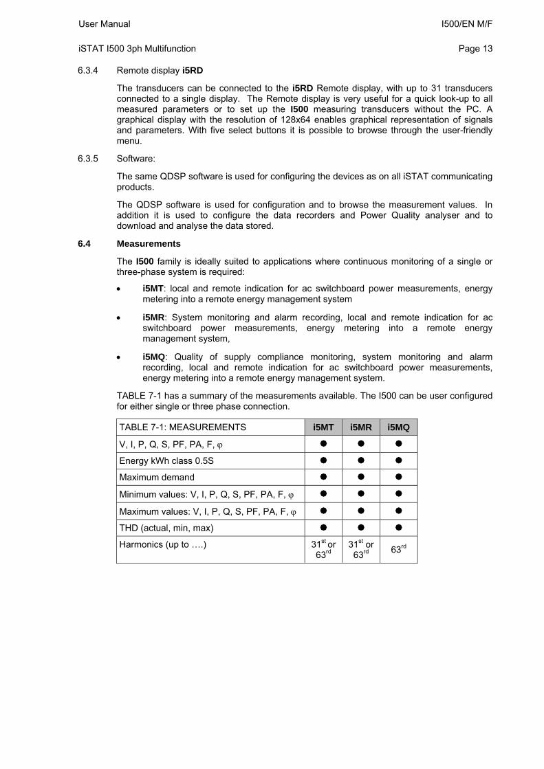
TABLE 7-1 has a summary of the measurements available. The I500 can be user configured for either single or three phase connection.
TABLE 7-1: MEASUREMENTS i5MT i5MR i5MQ
V, I, P, Q, S, PF, PA, F,
Energy kWh class 0.5S
Maximum demand
Minimum values: V, I, P, Q, S, PF, PA, F,
Maximum values: V, I, P, Q, S, PF, PA, F,
THD (actual, min, max)
Harmonics (up to ….) 31st or 63rd
31st or 63rd
63rd
I500/EN M/F User Manual Page 14
iSTAT I500 3ph Multifunction
6.5 Hardware features
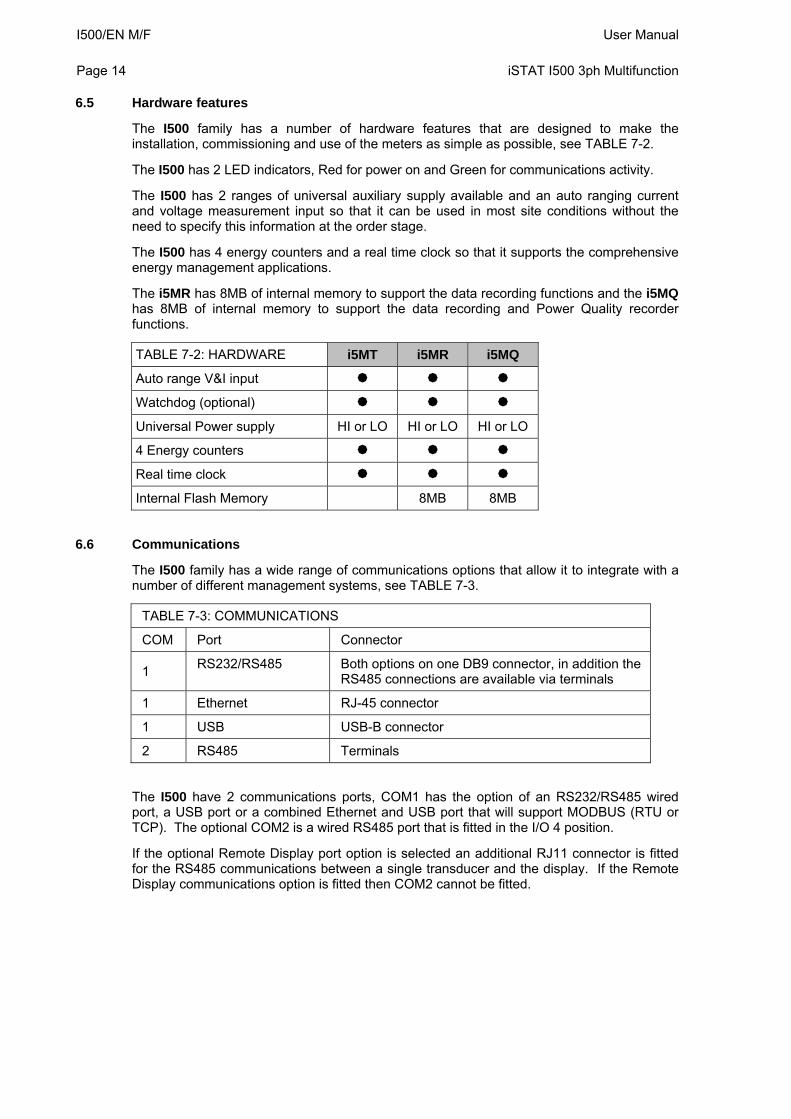
The I500 family has a number of hardware features that are designed to make the installation, commissioning and use of the meters as simple as possible, see TABLE 7-2.
The I500 has 2 LED indicators, Red for power on and Green for communications activity.
The I500 has 2 ranges of universal auxiliary supply available and an auto ranging current and voltage measurement input so that it can be used in most site conditions without the need to specify this information at the order stage.
The I500 has 4 energy counters and a real time clock so that it supports the comprehensive energy management applications.
The i5MR has 8MB of internal memory to support the data recording functions and the i5MQ has 8MB of internal memory to support the data recording and Power Quality recorder functions.
TABLE 7-2: HARDWARE i5MT i5MR i5MQ
Auto range V&I input
Watchdog (optional)
Universal Power supply HI or LO HI or LO HI or LO
4 Energy counters
Real time clock
Internal Flash Memory 8MB 8MB
6.6 Communications
The I500 family has a wide range of communications options that allow it to integrate with a number of different management systems, see TABLE 7-3.
TABLE 7-3: COMMUNICATIONS
COM Port Connector
1 RS232/RS485 Both options on one DB9 connector, in addition the
RS485 connections are available via terminals
1 Ethernet RJ-45 connector
1 USB USB-B connector
2 RS485 Terminals
The I500 have 2 communications ports, COM1 has the option of an RS232/RS485 wired port, a USB port or a combined Ethernet and USB port that will support MODBUS (RTU or TCP). The optional COM2 is a wired RS485 port that is fitted in the I/O 4 position.
If the optional Remote Display port option is selected an additional RJ11 connector is fitted for the RS485 communications between a single transducer and the display. If the Remote Display communications option is fitted then COM2 cannot be fitted.
User Manual I500/EN M/F iSTAT I500 3ph Multifunction
Page 15
6.7 Inputs and Outputs
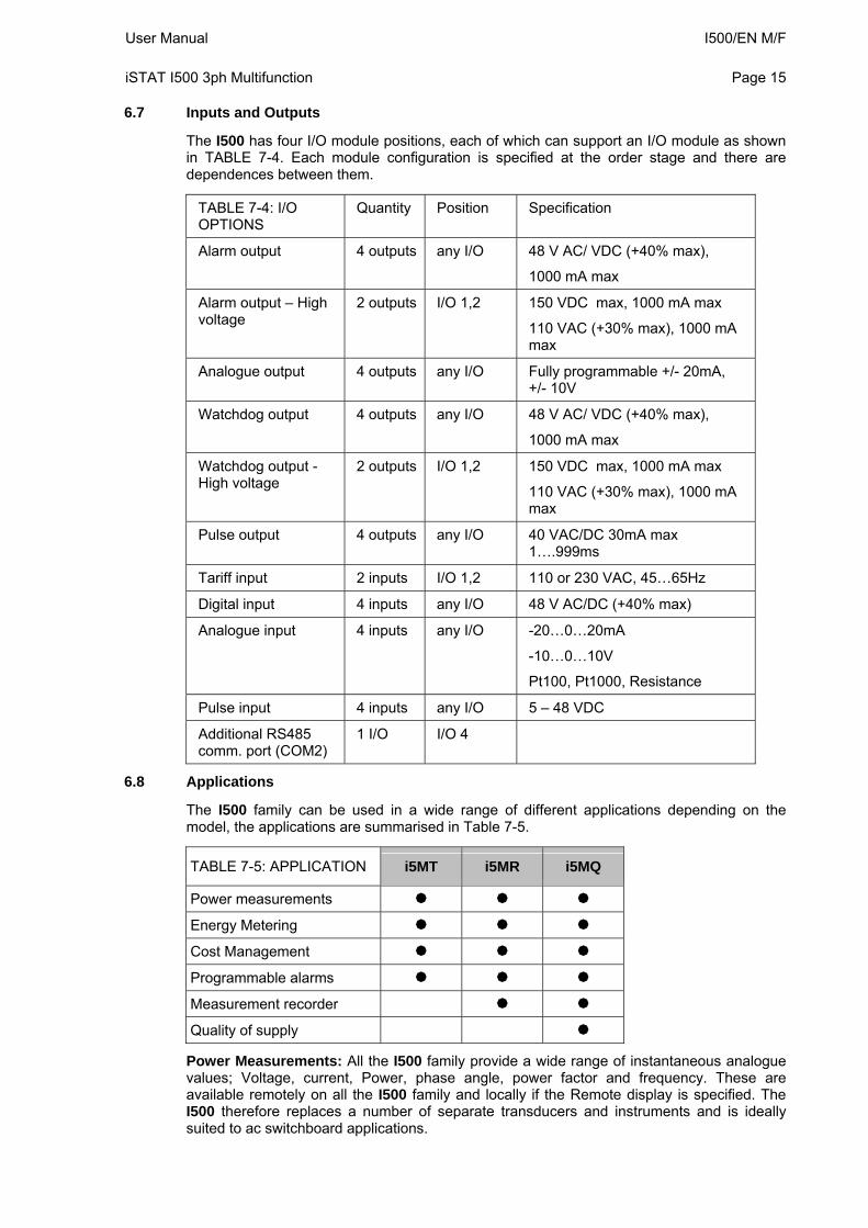
The I500 has four I/O module positions, each of which can support an I/O module as shown in TABLE 7-4. Each module configuration is specified at the order stage and there are dependences between them.
TABLE 7-4: I/O OPTIONS
Quantity Position Specification
Alarm output 4 outputs any I/O 48 V AC/ VDC (+40% max),
1000 mA max
Alarm output – High voltage
2 outputs I/O 1,2 150 VDC max, 1000 mA max
110 VAC (+30% max), 1000 mA max
Analogue output 4 outputs any I/O Fully programmable +/- 20mA, +/- 10V
Watchdog output 4 outputs any I/O 48 V AC/ VDC (+40% max),
1000 mA max
Watchdog output - High voltage
2 outputs I/O 1,2 150 VDC max, 1000 mA max
110 VAC (+30% max), 1000 mA max
Pulse output 4 outputs any I/O 40 VAC/DC 30mA max 1….999ms
Tariff input 2 inputs I/O 1,2 110 or 230 VAC, 45…65Hz
Digital input 4 inputs any I/O 48 V AC/DC (+40% max)
Analogue input 4 inputs any I/O -20…0…20mA
-10…0…10V
Pt100, Pt1000, Resistance
Pulse input 4 inputs any I/O 5 – 48 VDC
Additional RS485 comm. port (COM2)
1 I/O I/O 4
6.8 Applications
The I500 family can be used in a wide range of different applications depending on the model, the applications are summarised in Table 7-5.
TABLE 7-5: APPLICATION i5MT i5MR i5MQ
Power measurements
Energy Metering
Cost Management
Programmable alarms
Measurement recorder
Quality of supply
Power Measurements: All the I500 family provide a wide range of instantaneous analogue values; Voltage, current, Power, phase angle, power factor and frequency. These are available remotely on all the I500 family and locally if the Remote display is specified. The I500 therefore replaces a number of separate transducers and instruments and is ideally suited to ac switchboard applications.
I500/EN M/F User Manual Page 16
iSTAT I500 3ph Multifunction
Energy and sub Metering: With addition of 4 quadrant energy measurement, the I500 can be used in sub metering applications where information is passed to an energy management system to monitor the performance of the ac power system. Depending on the I500 model and options selected, the I500 can use a combination of pulsed energy contacts, tariff inputs and communications to integrate with and provide this data to the control system.
In addition, measurements such as maximum and minimum values and maximum demand information provide valuable information on the operation of plant and system monitoring to ensure that it is performing correctly.
Cost Management: The addition of a real time clock and a tariff structure means that the I500 can be used in stand-alone tariff or revenue sub metering applications. This allows the energy consumed to be given a financial cost that can vary depending on the time of day and season of the year. This provides information on the cost of plant operation and can be used to ensure that equipment and processes are used in the most financially efficient manner.
Measurement Recorder: The i5MR and i5MQ have up to 4 independent data recorders that provide trending information on up to 64 different analogue values. The type of value can be defined for each parameter, i.e. minimum, maximum, or average. Maximum demand and maximum and minimum instantaneous (every cycle) values can also be recorded. The status of all of the 32 software alarms can also be recorded within a separate alarm recorder. This provides a comprehensive record of the status of the monitoring system and a timed record of events.
Quality of supply: The i5MQ provides a quality of supply monitor that complies with the European standard EN50160. This power quality standard is used to monitor electrical systems and ensure that it falls within a number of different limits ensuring that the user has a consistent and correct supply of electricity.
User Manual I500/EN M/F iSTAT I500 3ph Multifunction
Page 17
7. HARDWARE
7.1 Communications
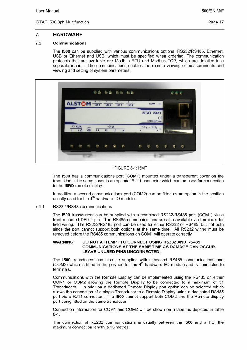
The I500 can be supplied with various communications options: RS232/RS485, Ethernet, USB or Ethernet and USB, which must be specified when ordering. The communication protocols that are available are Modbus RTU and Modbus TCP, which are detailed in a separate manual. The communications enables the remote viewing of measurements and viewing and setting of system parameters.
FIGURE 8-1: I5MT
The I500 has a communications port (COM1) mounted under a transparent cover on the front. Under the same cover is an optional RJ11 connector which can be used for connection to the i5RD remote display.
In addition a second communications port (COM2) can be fitted as an option in the position usually used for the 4th hardware I/O module.
7.1.1 RS232 /RS485 communications
The I500 transducers can be supplied with a combined RS232/RS485 port (COM1) via a front mounted DB9 9 pin. The RS485 communications are also available via terminals for field wiring. The RS232/RS485 port can be used for either RS232 or RS485, but not both since the port cannot support both options at the same time. All RS232 wiring must be removed before the RS485 communications on COM1 will operate correctly
WARNING: DO NOT ATTEMPT TO CONNECT USING RS232 AND RS485 COMMUNICATIONS AT THE SAME TIME AS DAMAGE CAN OCCUR. LEAVE UNUSED PINS UNCONNECTED.
The I500 transducers can also be supplied with a second RS485 communications port (COM2) which is fitted in the position for the 4th hardware I/O module and is connected to terminals.
Communications with the Remote Display can be implemented using the RS485 on either COM1 or COM2 allowing the Remote Display to be connected to a maximum of 31 Transducers. In addition a dedicated Remote Display port option can be selected which allows the connection of a single Transducer to a Remote Display using a dedicated RS485 port via a RJ11 connector. The I500 cannot support both COM2 and the Remote display port being fitted on the same transducer.
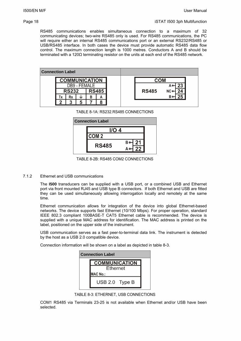
Connection information for COM1 and COM2 will be shown on a label as depicted in table 8-1.
The connection of RS232 communications is usually between the I500 and a PC, the maximum connection length is 15 metres.
I500/EN M/F User Manual Page 18
iSTAT I500 3ph Multifunction
RS485 communications enables simultaneous connection to a maximum of 32 communicating devices; two-wire RS485 only is used. For RS485 communications, the PC will require either an internal RS485 communications port or an external RS232/RS485 or USB/RS485 interface. In both cases the device must provide automatic RS485 data flow control. The maximum connection length is 1000 metres. Conductors A and B should be terminated with a 120Ω terminating resistor on the units at each end of the RS485 network.
Connection Label
TABLE 8-1A: RS232.RS485 CONNECTIONS
Connection Label
TABLE 8-2B: RS485 COM2 CONNECTIONS
7.1.2 Ethernet and USB communications
The I500 transducers can be supplied with a USB port, or a combined USB and Ethernet port via front mounted RJ45 and USB type B connectors. If both Ethernet and USB are fitted they can be used simultaneously allowing interrogation locally and remotely at the same time.
Ethernet communication allows for integration of the device into global Ethernet-based networks. The device supports fast Ethernet (10/100 Mbps). For proper operation, standard IEEE 802.3 compliant 100BASE-T CAT5 Ethernet cable is recommended. The device is supplied with a unique MAC address for identification. The MAC address is printed on the label, positioned on the upper side of the instrument.
USB communication serves as a fast peer-to-terminal data link. The instrument is detected by the host as a USB 2.0 compatible device.
Connection information will be shown on a label as depicted in table 8-3.
Connection Label
TABLE 8-3: ETHERNET, USB CONNECTIONS
COM1 RS485 via Terminals 23-25 is not available when Ethernet and/or USB have been selected.
User Manual I500/EN M/F iSTAT I500 3ph Multifunction
Page 19
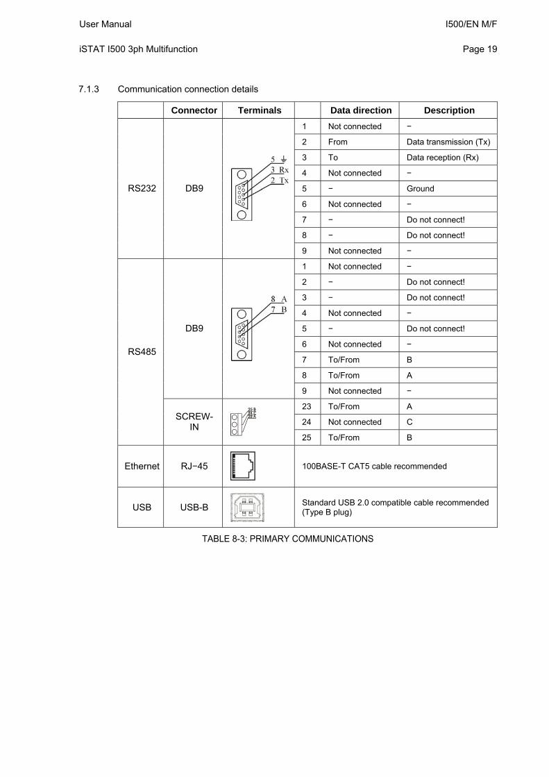
7.1.3 Communication connection details
Connector Terminals Data direction Description
1 Not connected −
2 From Data transmission (Tx)
3 To Data reception (Rx)
4 Not connected −
5 − Ground
6 Not connected −
7 − Do not connect!
8 − Do not connect!
RS232 DB9
9 Not connected −
1 Not connected −
2 − Do not connect!
3 − Do not connect!
4 Not connected −
5 − Do not connect!
6 Not connected −
7 To/From B
8 To/From A
DB9
9 Not connected −
23 To/From A
24 Not connected C
RS485
SCREW-IN
25 To/From B
Ethernet RJ−45
100BASE-T CAT5 cable recommended
USB USB-B
Standard USB 2.0 compatible cable recommended (Type B plug)
TABLE 8-3: PRIMARY COMMUNICATIONS
I500/EN M/F User Manual Page 20
iSTAT I500 3ph Multifunction
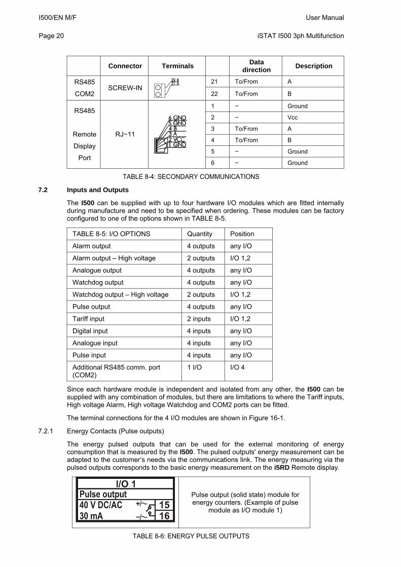
Connector Terminals
Data direction
Description
21 To/From A RS485
COM2 SCREW-IN
22 To/From B
1 − Ground
2 − Vcc
3 To/From A
4 To/From B
5 − Ground
RS485
Remote
Display
Port
RJ−11
6 − Ground
TABLE 8-4: SECONDARY COMMUNICATIONS
7.2 Inputs and Outputs
The I500 can be supplied with up to four hardware I/O modules which are fitted internally during manufacture and need to be specified when ordering. These modules can be factory configured to one of the options shown in TABLE 8-5.
TABLE 8-5: I/O OPTIONS Quantity Position
Alarm output 4 outputs any I/O
Alarm output – High voltage 2 outputs I/O 1,2
Analogue output 4 outputs any I/O
Watchdog output 4 outputs any I/O
Watchdog output – High voltage 2 outputs I/O 1,2
Pulse output 4 outputs any I/O
Tariff input 2 inputs I/O 1,2
Digital input 4 inputs any I/O
Analogue input 4 inputs any I/O
Pulse input 4 inputs any I/O
Additional RS485 comm. port (COM2)
1 I/O I/O 4
Since each hardware module is independent and isolated from any other, the I500 can be supplied with any combination of modules, but there are limitations to where the Tariff inputs, High voltage Alarm, High voltage Watchdog and COM2 ports can be fitted.
The terminal connections for the 4 I/O modules are shown in Figure 16-1.
7.2.1 Energy Contacts (Pulse outputs)
The energy pulsed outputs that can be used for the external monitoring of energy consumption that is measured by the I500. The pulsed outputs' energy measurement can be adapted to the customer’s needs via the communications link. The energy measuring via the pulsed outputs corresponds to the basic energy measurement on the i5RD Remote display.
Pulse output (solid state) module for energy counters. (Example of pulse
module as I/O module 1)
TABLE 8-6: ENERGY PULSE OUTPUTS
User Manual I500/EN M/F iSTAT I500 3ph Multifunction
Page 21
When all hardware modules are used for energy contacts, the I500 will provide a maximum of 4 independent pulse outputs.
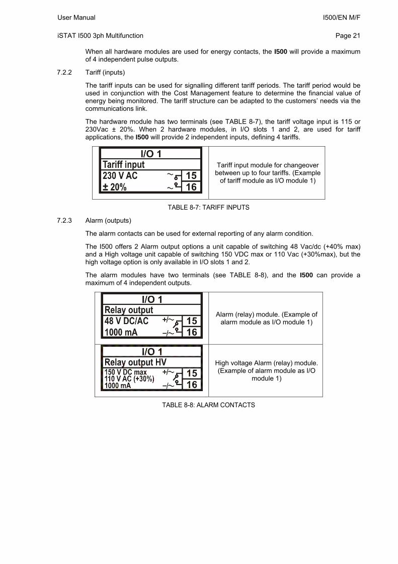
7.2.2 Tariff (inputs)
The tariff inputs can be used for signalling different tariff periods. The tariff period would be used in conjunction with the Cost Management feature to determine the financial value of energy being monitored. The tariff structure can be adapted to the customers’ needs via the communications link.
The hardware module has two terminals (see TABLE 8-7), the tariff voltage input is 115 or 230Vac ± 20%. When 2 hardware modules, in I/O slots 1 and 2, are used for tariff applications, the I500 will provide 2 independent inputs, defining 4 tariffs.
Tariff input module for changeover between up to four tariffs. (Example
of tariff module as I/O module 1)
TABLE 8-7: TARIFF INPUTS
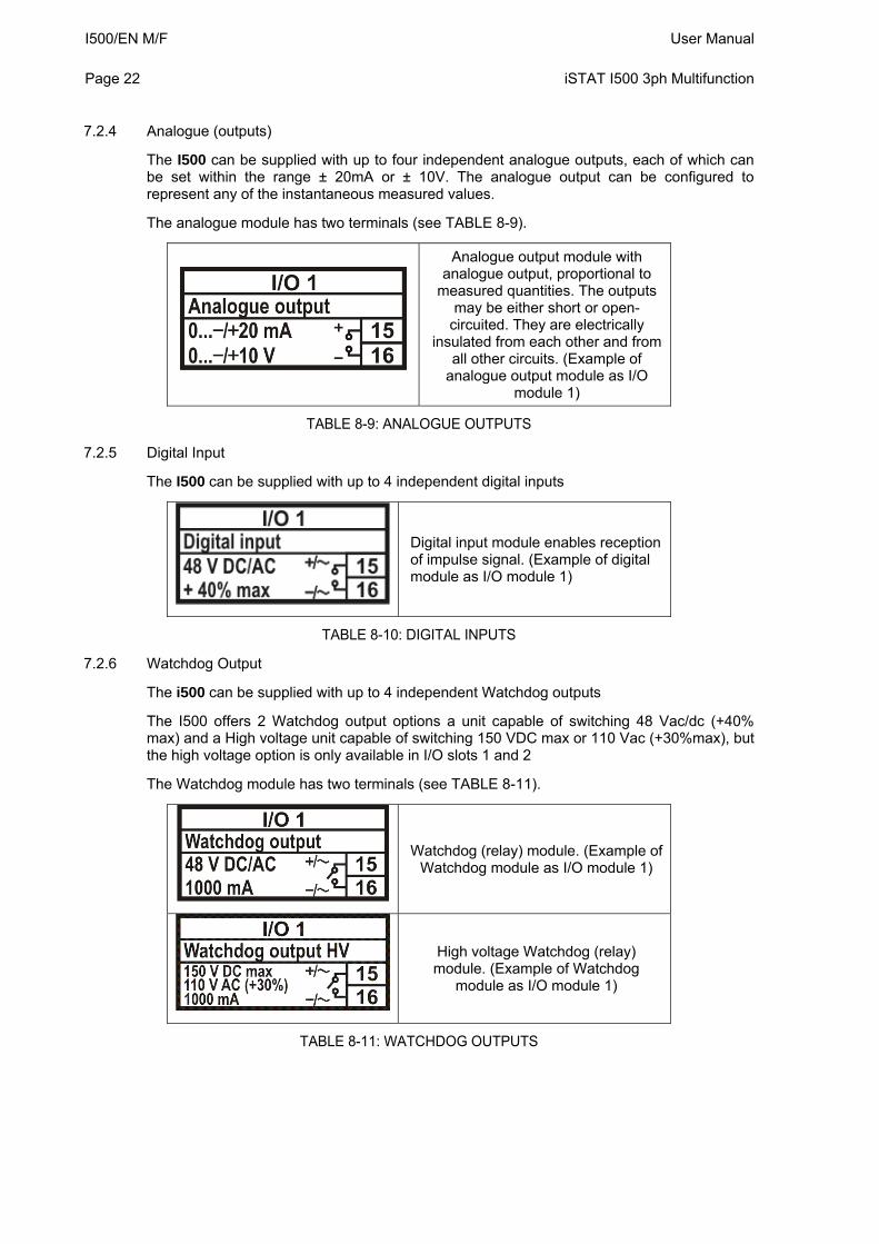
7.2.3 Alarm (outputs)
The alarm contacts can be used for external reporting of any alarm condition.
The I500 offers 2 Alarm output options a unit capable of switching 48 Vac/dc (+40% max) and a High voltage unit capable of switching 150 VDC max or 110 Vac (+30%max), but the high voltage option is only available in I/O slots 1 and 2.
The alarm modules have two terminals (see TABLE 8-8), and the I500 can provide a maximum of 4 independent outputs.
Alarm (relay) module. (Example of alarm module as I/O module 1)
High voltage Alarm (relay) module. (Example of alarm module as I/O
module 1)
TABLE 8-8: ALARM CONTACTS
I500/EN M/F User Manual Page 22
iSTAT I500 3ph Multifunction
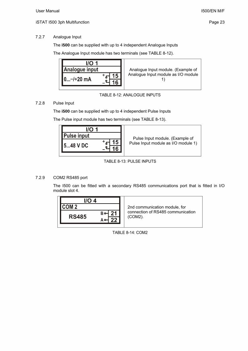
7.2.4 Analogue (outputs)
The I500 can be supplied with up to four independent analogue outputs, each of which can be set within the range ± 20mA or ± 10V. The analogue output can be configured to represent any of the instantaneous measured values.
The analogue module has two terminals (see TABLE 8-9).
Analogue output module with analogue output, proportional to
measured quantities. The outputs may be either short or open-
circuited. They are electrically insulated from each other and from
all other circuits. (Example of analogue output module as I/O
module 1)
TABLE 8-9: ANALOGUE OUTPUTS
7.2.5 Digital Input
The I500 can be supplied with up to 4 independent digital inputs
Digital input module enables reception of impulse signal. (Example of digital module as I/O module 1)
TABLE 8-10: DIGITAL INPUTS
7.2.6 Watchdog Output
The i500 can be supplied with up to 4 independent Watchdog outputs
The I500 offers 2 Watchdog output options a unit capable of switching 48 Vac/dc (+40% max) and a High voltage unit capable of switching 150 VDC max or 110 Vac (+30%max), but the high voltage option is only available in I/O slots 1 and 2
The Watchdog module has two terminals (see TABLE 8-11).
Watchdog (relay) module. (Example of Watchdog module as I/O module 1)
High voltage Watchdog (relay) module. (Example of Watchdog
module as I/O module 1)
TABLE 8-11: WATCHDOG OUTPUTS
User Manual I500/EN M/F iSTAT I500 3ph Multifunction
Page 23
7.2.7 Analogue Input
The i500 can be supplied with up to 4 independent Analogue Inputs
The Analogue Input module has two terminals (see TABLE 8-12).
Analogue Input module. (Example of Analogue Input module as I/O module
1)
TABLE 8-12: ANALOGUE INPUTS
7.2.8 Pulse Input
The i500 can be supplied with up to 4 independent Pulse Inputs
The Pulse input module has two terminals (see TABLE 8-13).
Pulse Input module. (Example of Pulse Input module as I/O module 1)
TABLE 8-13: PULSE INPUTS
7.2.9 COM2 RS485 port
The I500 can be fitted with a secondary RS485 communications port that is fitted in I/O module slot 4.
2nd communication module, for connection of RS485 communication (COM2).
TABLE 8-14: COM2
I500/EN M/F User Manual Page 24
iSTAT I500 3ph Multifunction
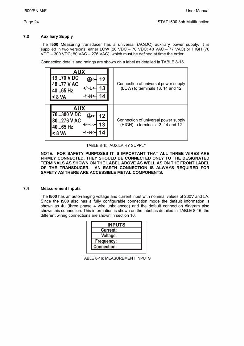
7.3 Auxiliary Supply
The I500 Measuring transducer has a universal (AC/DC) auxiliary power supply. It is supplied in two versions, either LOW (20 VDC – 70 VDC; 48 VAC – 77 VAC) or HIGH (70 VDC – 300 VDC; 80 VAC – 276 VAC), which must be defined at time the order.
Connection details and ratings are shown on a label as detailed in TABLE 8-15.
Connection of universal power supply (LOW) to terminals 13, 14 and 12
Connection of universal power supply (HIGH) to terminals 13, 14 and 12
TABLE 8-15: AUXILAIRY SUPPLY
NOTE: FOR SAFETY PURPOSES IT IS IMPORTANT THAT ALL THREE WIRES ARE FIRMLY CONNECTED. THEY SHOULD BE CONNECTED ONLY TO THE DESIGNATED TERMINALS AS SHOWN ON THE LABEL ABOVE AS WELL AS ON THE FRONT LABEL OF THE TRANSDUCER. AN EARTH CONNECTION IS ALWAYS REQUIRED FOR SAFETY AS THERE ARE ACCESSIBLE METAL COMPONENTS.
7.4 Measurement Inputs
The I500 has an auto-ranging voltage and current input with nominal values of 230V and 5A. Since the I500 also has a fully configurable connection mode the default information is shown as 4u (three phase 4 wire unbalanced) and the default connection diagram also shows this connection. This information is shown on the label as detailed in TABLE 8-16, the different wiring connections are shown in section 16.
TABLE 8-16: MEASUREMENT INPUTS
User Manual I500/EN M/F iSTAT I500 3ph Multifunction
Page 25
8. SETTINGS
8.1 Introduction
Instrument settings can be remotely modified with the QDSP software, when connected to a PC, or with the use of the keyboard on the i5RD Remote display if fitted. The settings that can be modified using the i5RD Remote display are indicated by (RD) in the sections below.
8.2 QDSP Software
QDSP is a software tool for complete monitoring of measuring instruments, connected to a PC via serial or TCP/IP communication. A user-friendly interface consists of five segments: devices management, instrument settings, real-time measurements, data analysis and software upgrading.
A separate QDSP manual is available that defines the operation of QDSP in detail.
8.2.1 Devices Management
The communications parameters for any connected device can be modified. Also included are browsers which scan the communications networks attached to the PC and identify all of the devices connected with their addresses and communications parameters. This can be done on RS232, RS485, USB and Ethernet connections.
8.2.2 Instrument settings
The instrument settings are organized in a tree structure and they can be modified simply as required. In addition to transferring settings to the instrument, QDSP can also store the data to settings files and read it back when required.
8.2.3 Real time measurements
All measurements can be displayed in real time in a table. Harmonics and their time-reconstruct signals are displayed graphically.
If further processing of the measurement data is required it can be copied via a clipboard and inserted into standard Windows formats.
8.2.4 Data Analysis
Analysis can be performed on the recorded data in the i5MR and i5MQ. Recorded values can be displayed in a tabular or graphical form. The events that triggered alarms can be analysed or a report on supply voltage quality can be made. All data can be exported to an Access database, Excel worksheet or a text file.
8.2.5 Software upgrading
It is suggested that the latest version of QDSP should always be used and if the system is also connected to the internet if will define if an upgrade is available for download.
I500/EN M/F User Manual Page 26
iSTAT I500 3ph Multifunction
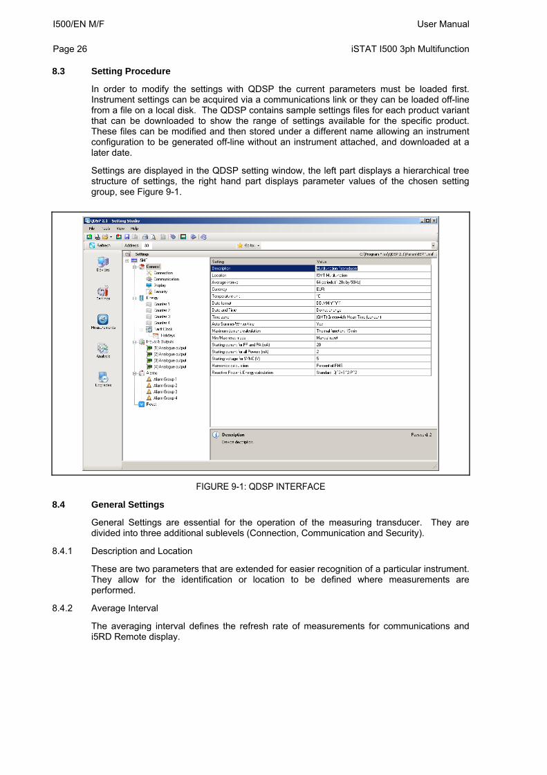
8.3 Setting Procedure
In order to modify the settings with QDSP the current parameters must be loaded first. Instrument settings can be acquired via a communications link or they can be loaded off-line from a file on a local disk. The QDSP contains sample settings files for each product variant that can be downloaded to show the range of settings available for the specific product. These files can be modified and then stored under a different name allowing an instrument configuration to be generated off-line without an instrument attached, and downloaded at a later date.
Settings are displayed in the QDSP setting window, the left part displays a hierarchical tree structure of settings, the right hand part displays parameter values of the chosen setting group, see Figure 9-1.
FIGURE 9-1: QDSP INTERFACE
8.4 General Settings
General Settings are essential for the operation of the measuring transducer. They are divided into three additional sublevels (Connection, Communication and Security).
8.4.1 Description and Location
These are two parameters that are extended for easier recognition of a particular instrument. They allow for the identification or location to be defined where measurements are performed.
8.4.2 Average Interval
The averaging interval defines the refresh rate of measurements for communications and i5RD Remote display.
User Manual I500/EN M/F iSTAT I500 3ph Multifunction
Page 27
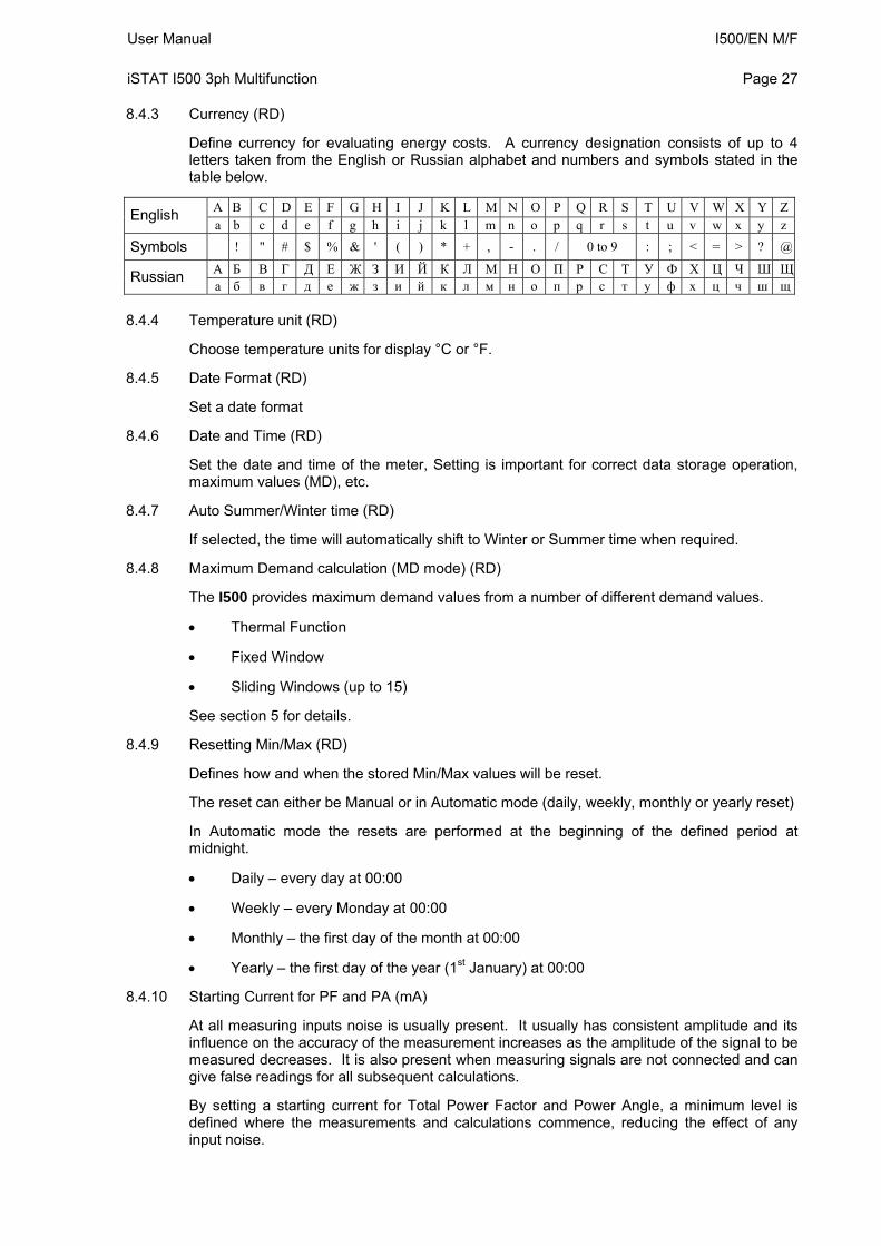
8.4.3 Currency (RD)
Define currency for evaluating energy costs. A currency designation consists of up to 4 letters taken from the English or Russian alphabet and numbers and symbols stated in the table below.
A B C D E F G H I J K L M N O P Q R S T U V W X Y ZEnglish
a b c d e f g h i j k l m n o p q r s t u v w x y z
Symbols ! " # $ % & ' ( ) * + , - . / 0 to 9 : ; < = > ? @
А Б В Г Д Е Ж З И Й К Л М Н O П P С Т У Ф Х Ц Ч Ш ЩRussian
а б в г д е ж з и й к л м н o п p с т у ф х ц ч ш щ 8.4.4 Temperature unit (RD)
Choose temperature units for display °C or °F.
8.4.5 Date Format (RD)
Set a date format
8.4.6 Date and Time (RD)
Set the date and time of the meter, Setting is important for correct data storage operation, maximum values (MD), etc.
8.4.7 Auto Summer/Winter time (RD)
If selected, the time will automatically shift to Winter or Summer time when required.
8.4.8 Maximum Demand calculation (MD mode) (RD)
The I500 provides maximum demand values from a number of different demand values.
Thermal Function
Fixed Window
Sliding Windows (up to 15)
See section 5 for details.
8.4.9 Resetting Min/Max (RD)
Defines how and when the stored Min/Max values will be reset.
The reset can either be Manual or in Automatic mode (daily, weekly, monthly or yearly reset)
In Automatic mode the resets are performed at the beginning of the defined period at midnight.
Daily – every day at 00:00
Weekly – every Monday at 00:00
Monthly – the first day of the month at 00:00
Yearly – the first day of the year (1st January) at 00:00
8.4.10 Starting Current for PF and PA (mA)
At all measuring inputs noise is usually present. It usually has consistent amplitude and its influence on the accuracy of the measurement increases as the amplitude of the signal to be measured decreases. It is also present when measuring signals are not connected and can give false readings for all subsequent calculations.
By setting a starting current for Total Power Factor and Power Angle, a minimum level is defined where the measurements and calculations commence, reducing the effect of any input noise.
I500/EN M/F User Manual Page 28
iSTAT I500 3ph Multifunction
8.4.11 Starting current for all powers (mA)
By setting a Minimum Starting Current, a level is defined where the measurements of Current and calculation of all powers commence, reducing the effect of any input noise.
8.4.12 Calculation of Harmonics
The selection of the reference for the calculation of harmonics is important for the calculation of the absolute values. It is possible to select harmonics
As a percentage of the RMS signal value where a value is calculated for all harmonics
Or relative to the fundamental (first harmonic) where all other harmonics are calculated relative to the 1st harmonic.
8.4.13 Reactive power calculation
Two different principles of reactive power and energy calculation are used:
Standard method:
With this method a reactive power and energy are calculated based on assumption that all power (energy) that is not active is reactive.
Q2 = S2 – P2
This means also that all higher harmonics will be measured as reactive power (energy).
Delayed current method:
With this method, reactive power (energy) is calculated by multiplication of voltage samples and delayed current samples.
Q = U × I|+90°
With this method, reactive power (energy) represents only true reactive component of apparent power (energy).
8.5 Connection
The setting of the connection parameters must reflect the actual applications or the measurements will not be valid.
All of the settings in this section should be defined before the settings for the analogue and alarm outputs, as changes to this section may automatically change the measurements and output settings.
User Manual I500/EN M/F iSTAT I500 3ph Multifunction
Page 29
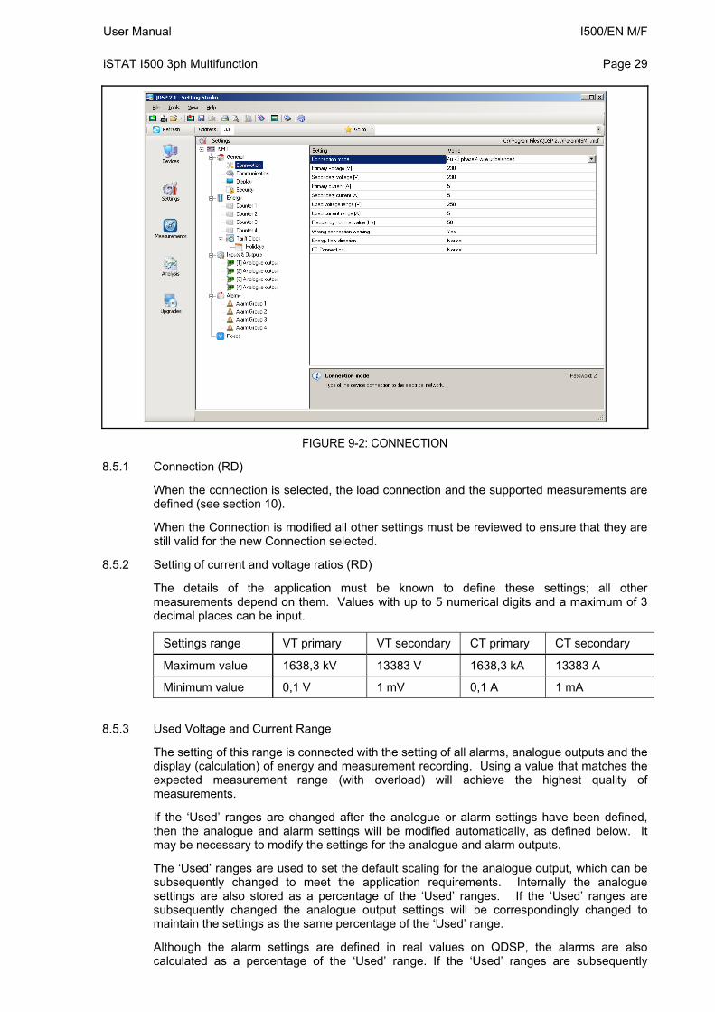
FIGURE 9-2: CONNECTION
8.5.1 Connection (RD)
When the connection is selected, the load connection and the supported measurements are defined (see section 10).
When the Connection is modified all other settings must be reviewed to ensure that they are still valid for the new Connection selected.
8.5.2 Setting of current and voltage ratios (RD)
The details of the application must be known to define these settings; all other measurements depend on them. Values with up to 5 numerical digits and a maximum of 3 decimal places can be input.
Settings range VT primary VT secondary CT primary CT secondary
Maximum value 1638,3 kV 13383 V 1638,3 kA 13383 A
Minimum value 0,1 V 1 mV 0,1 A 1 mA
8.5.3 Used Voltage and Current Range
The setting of this range is connected with the setting of all alarms, analogue outputs and the display (calculation) of energy and measurement recording. Using a value that matches the expected measurement range (with overload) will achieve the highest quality of measurements.
If the ‘Used’ ranges are changed after the analogue or alarm settings have been defined, then the analogue and alarm settings will be modified automatically, as defined below. It may be necessary to modify the settings for the analogue and alarm outputs.
The ‘Used’ ranges are used to set the default scaling for the analogue output, which can be subsequently changed to meet the application requirements. Internally the analogue settings are also stored as a percentage of the ‘Used’ ranges. If the ‘Used’ ranges are subsequently changed the analogue output settings will be correspondingly changed to maintain the settings as the same percentage of the ‘Used’ range.
Although the alarm settings are defined in real values on QDSP, the alarms are also calculated as a percentage of the ‘Used’ range. If the ‘Used’ ranges are subsequently
I500/EN M/F User Manual Page 30
iSTAT I500 3ph Multifunction
changed the alarm settings will be correspondingly changed to maintain the settings as the same percentage of the ‘Used’ range.
8.5.4 Nominal Frequency
A valid frequency measurement is within ± 32Hz of the nominal frequency. This setting is only used for alarms and recorders.
8.6 Communication
The settings displayed depend on the hardware options on the specific instrument connected or the settings in the specific settings file that is being worked on off-line.
8.6.1 Serial Communication parameters (COM1) (RD)
These parameters are important for the correct operation in RS485 networks or connections with PC via RS232 communications. Factory settings for communication are #33\19200,n,8,2 (previous default #33\115200,n,8,2) (address 1 to 247\data rate 2400 to 115200 b/s, parity, data bits, stop bit). To find the communications parameters of a specific product use the ‘Scan the Network’ feature on QDSP.
8.6.2 Ethernet Communication
8.6.2.1 Device Address (RD)
The device address should be maintained at the default value of 33.
8.6.2.2 IP address (RD)
The communication interface should have a unique IP address in the Ethernet network. Two modes for assigning IP are described
Fixed IP address: In most installations a fixed IP address is required. A system provider usually defines IP addresses. An IP address should be within a valid IP range, unique for your network and in the same sub-network as your PC.
DHCP: An automatic method of assigning IP addresses (DHCP) is used in most networks. If you are not sure if DHCP is used on your network, check it with your system provider.
8.6.2.3 Local Port (RD)
Use a non-reserved port number from 1025 to 65535. Do not set the Local Port to any of the reserved port numbers.
If using Redirector software, the port number should be between 14000 and 14009.
Port numbers Function
1 – 1024, 9999, 30718, 33333 Reserved numbers
14000 – 14009 Reserved for Redirector
Factory settings for Ethernet Communications are:
IP Address DHCP (automatically)
TCP Port 10001
Subnet Mask 255.255.255.0
8.6.3 USB
The transducer will be identified as a USB device when connected to a USB port on the PC, refer to the separate QDSP manual for details of the driver installation.
User Manual I500/EN M/F iSTAT I500 3ph Multifunction
Page 31
8.7 Security
Parameter settings are divided into 2 groups for regarding security level:
1. If the passwords are set to ‘AAAA’ (default) there is no restriction to the access of parameter settings.
2. At the first level (PL1), the settings for the real time clock and the reset of the energy registers and MD can be accessed.
3. At the second level (PL2), access is given to all parameter settings.
4. Change to the language setting is possible without inputting a password. When language is changed to or from Russian, character transformation has to be taken in to account, see section 6.2.
5. A Backup password (BP) is used if the passwords at level 1 (PL1) and level2 (PL2) have been forgotten, and it is different for each device depending on the serial number of the instrument. The BP password is available from the customer support department of Alstom Grid, and is entered instead of password PL1 and/or PL2. The serial number is stated on the product label or can be read with QDSP and must be supplied when requesting the BP.
6. Passwords are the same regardless of which communications port (COM1 or COM2) the user is accessing for the settings. But unlocking the access via COM1 doesn’t unlock the access via COM2 and vice versa.
8.7.1 Password setting (RD)
A password consists of four capital letters taken from the British alphabet from A to Z. When setting a password, only the letter being set is visible, while the others are covered with an asterisk.
Two passwords (PL1, PL2) and the time after which they become active, can be set.
8.7.2 Password modification (RD)
A password can be modified; however only the password whose access has been unlocked (password entered) can be modified.
To disable a password previously set, modify the password back to ‘AAAA’.
8.8 Energy
The parameters defining the energy measurement and totalising can be modified. After modifications have been done the energy meters must be reset or all subsequent energy measurements will be incorrect.
I500/EN M/F User Manual Page 32
iSTAT I500 3ph Multifunction
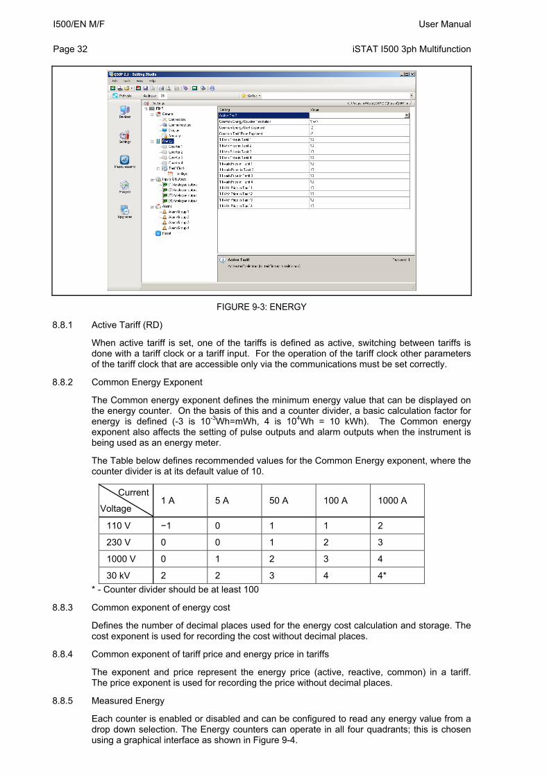
FIGURE 9-3: ENERGY
8.8.1 Active Tariff (RD)
When active tariff is set, one of the tariffs is defined as active, switching between tariffs is done with a tariff clock or a tariff input. For the operation of the tariff clock other parameters of the tariff clock that are accessible only via the communications must be set correctly.
8.8.2 Common Energy Exponent
The Common energy exponent defines the minimum energy value that can be displayed on the energy counter. On the basis of this and a counter divider, a basic calculation factor for energy is defined (-3 is 10-3Wh=mWh, 4 is 104Wh = 10 kWh). The Common energy exponent also affects the setting of pulse outputs and alarm outputs when the instrument is being used as an energy meter.
The Table below defines recommended values for the Common Energy exponent, where the counter divider is at its default value of 10.
Current
Voltage 1 A 5 A 50 A 100 A 1000 A
110 V −1 0 1 1 2
230 V 0 0 1 2 3
1000 V 0 1 2 3 4
30 kV 2 2 3 4 4*
* - Counter divider should be at least 100
8.8.3 Common exponent of energy cost
Defines the number of decimal places used for the energy cost calculation and storage. The cost exponent is used for recording the cost without decimal places.
8.8.4 Common exponent of tariff price and energy price in tariffs
The exponent and price represent the energy price (active, reactive, common) in a tariff. The price exponent is used for recording the price without decimal places.
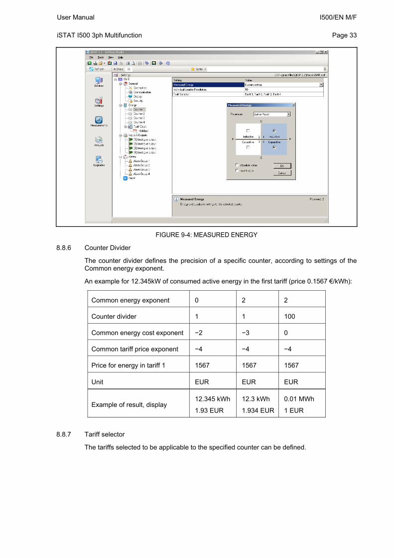
8.8.5 Measured Energy
Each counter is enabled or disabled and can be configured to read any energy value from a drop down selection. The Energy counters can operate in all four quadrants; this is chosen using a graphical interface as shown in Figure 9-4.
User Manual I500/EN M/F iSTAT I500 3ph Multifunction
Page 33
FIGURE 9-4: MEASURED ENERGY
8.8.6 Counter Divider
The counter divider defines the precision of a specific counter, according to settings of the Common energy exponent.
An example for 12.345kW of consumed active energy in the first tariff (price 0.1567 €/kWh):
Common energy exponent 0 2 2
Counter divider 1 1 100
Common energy cost exponent −2 −3 0
Common tariff price exponent −4 −4 −4
Price for energy in tariff 1 1567 1567 1567
Unit EUR EUR EUR
Example of result, display 12.345 kWh
1.93 EUR
12.3 kWh
1.934 EUR
0.01 MWh
1 EUR
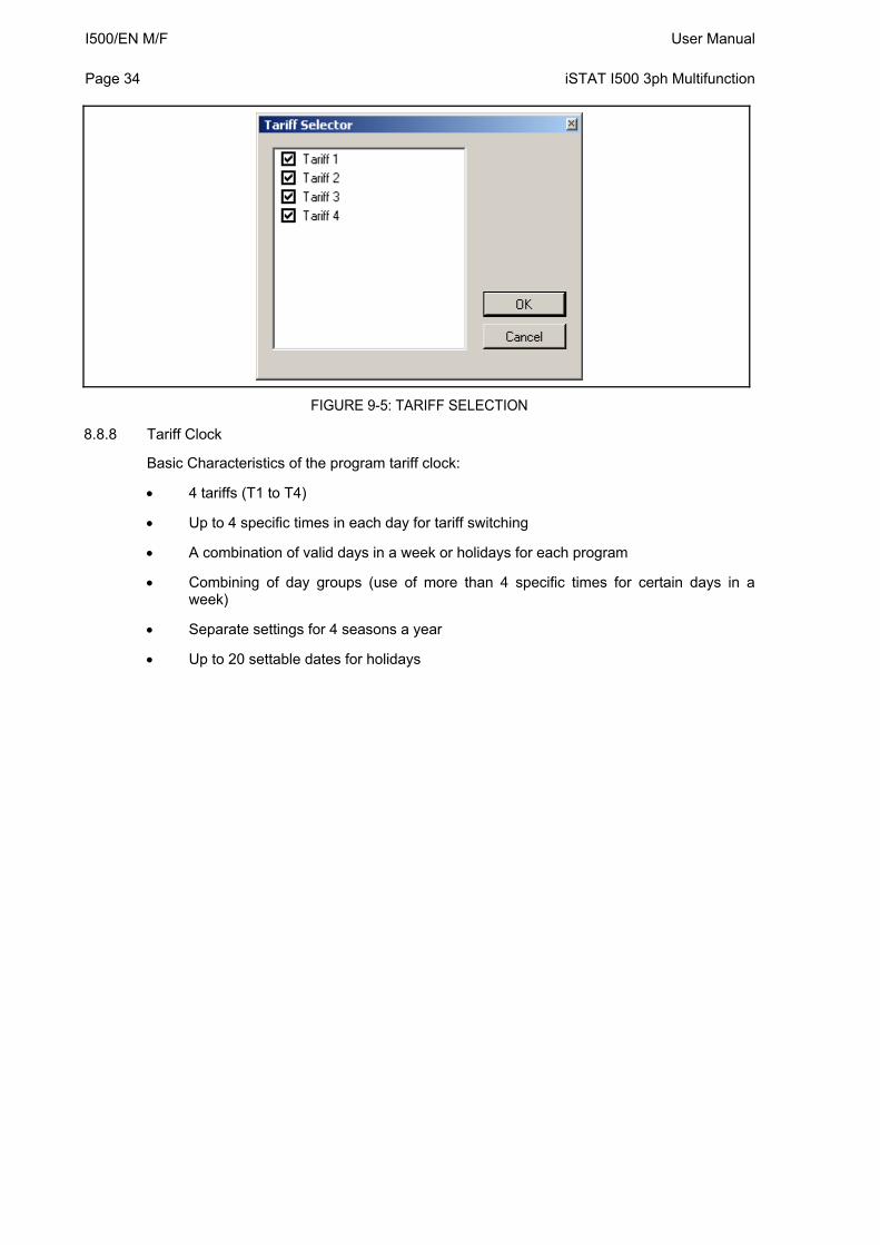
8.8.7 Tariff selector
The tariffs selected to be applicable to the specified counter can be defined.
I500/EN M/F User Manual Page 34
iSTAT I500 3ph Multifunction
FIGURE 9-5: TARIFF SELECTION
8.8.8 Tariff Clock
Basic Characteristics of the program tariff clock:
4 tariffs (T1 to T4)
Up to 4 specific times in each day for tariff switching
A combination of valid days in a week or holidays for each program
Combining of day groups (use of more than 4 specific times for certain days in a week)
Separate settings for 4 seasons a year
Up to 20 settable dates for holidays
User Manual I500/EN M/F iSTAT I500 3ph Multifunction
Page 35
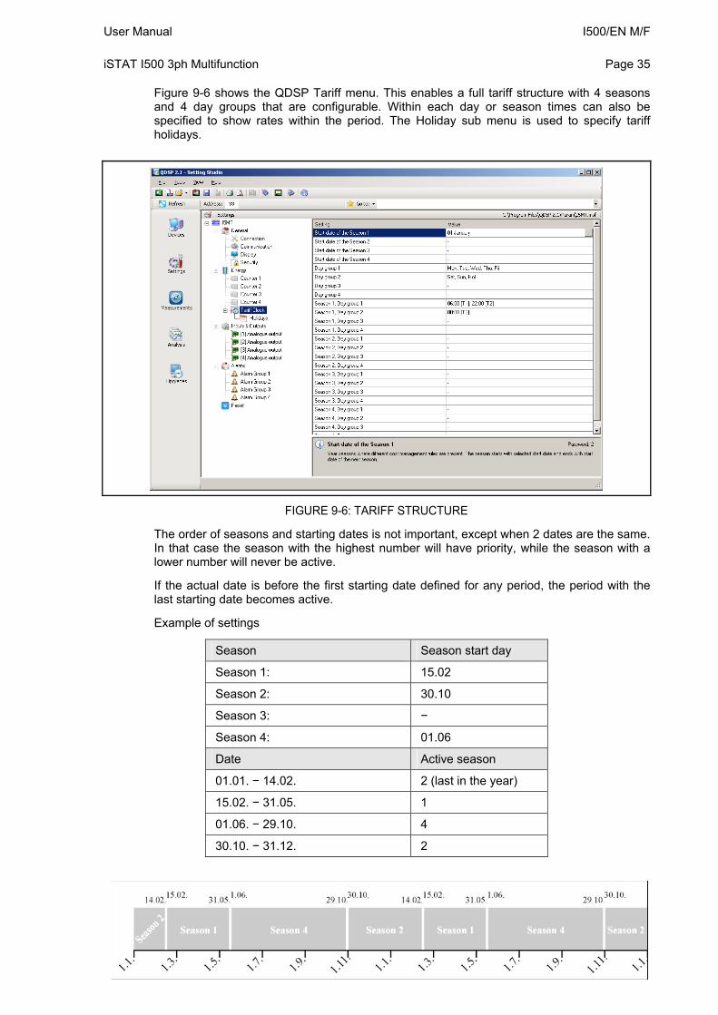
Figure 9-6 shows the QDSP Tariff menu. This enables a full tariff structure with 4 seasons and 4 day groups that are configurable. Within each day or season times can also be specified to show rates within the period. The Holiday sub menu is used to specify tariff holidays.
FIGURE 9-6: TARIFF STRUCTURE
The order of seasons and starting dates is not important, except when 2 dates are the same. In that case the season with the highest number will have priority, while the season with a lower number will never be active.
If the actual date is before the first starting date defined for any period, the period with the last starting date becomes active.
Example of settings
Season Season start day
Season 1: 15.02
Season 2: 30.10
Season 3: −
Season 4: 01.06
Date Active season
01.01. − 14.02. 2 (last in the year)
15.02. − 31.05. 1
01.06. − 29.10. 4
30.10. − 31.12. 2
I500/EN M/F User Manual Page 36
iSTAT I500 3ph Multifunction
Several daily groups can be active simultaneously, which enables more than 4 time slots in one day (Combination of day programs)
8.9 Inputs and Outputs
The module settings displayed will depend on the I/O modules built in to the instrument or defined in the settings file if working off-line.
8.9.1 Analogue output module
Each of the analogue outputs is fully programmable.
8.9.1.1 Output parameter
Define the Measured or calculated parameter that is to be output on the specific analogue output. This can include the value from an analogue input channel.
8.9.1.2 Output range
The analogue output can be configured to one of six hardware output ranges within which the analogue output will operate. To ensure the highest accuracy for the output, the range selected should be the lowest that covers the required analogue output range.
DC current output DC voltage output
-1…0…1 mA -1…0…1 V
-5…0…5 mA
-10...0...10 mA -10…0…10 V
-20...0...20 mA
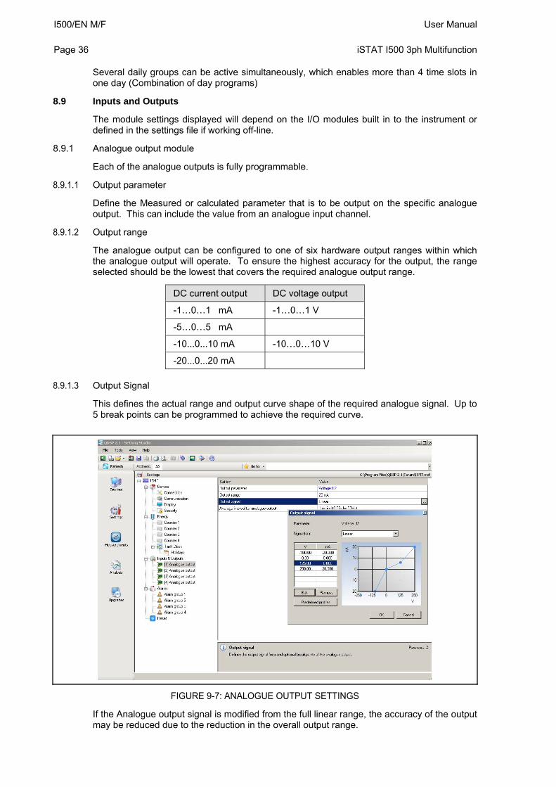
8.9.1.3 Output Signal
This defines the actual range and output curve shape of the required analogue signal. Up to 5 break points can be programmed to achieve the required curve.
FIGURE 9-7: ANALOGUE OUTPUT SETTINGS
If the Analogue output signal is modified from the full linear range, the accuracy of the output may be reduced due to the reduction in the overall output range.
User Manual I500/EN M/F iSTAT I500 3ph Multifunction
Page 37
Note: If the ‘Used’ ranges are changed after the analogue settings have been defined, then the analogue settings will be modified automatically, see section 9.5.3. It may be necessary to subsequently modify the settings for the analogue outputs.
8.9.1.4 Average interval for analogue output
Defines the time interval over which the measurement used for an analogue output will be averaged.
8.9.2 Alarm/Digital Output Module (RD)
Alarm groups that are connected with an alarm module and a signal shape are defined
An alarm module can also function as a pulse output with limited pulse length (min 10ms) or a general purpose digital output. The settings for the pulse option are defined in the same way as for the pulse module. A parallel RC filter with a time constant of at least 150 µs (R*C ≥ 250 µs) should be fitted when connected to a sensitive pulse counter, to attenuate the relay transient signals.
8.9.2.1 Output signal
The alarm/digital output can be configured for a number of different signal shapes:
Normal – The relay is closed until the alarm condition is fulfilled.
Normal Inverse – The relay is open until the alarm condition is fulfilled.
Holds – The relay is closed when the alarm condition is fulfilled, and remains closed until it is reset via communication.
Pulse – an impulse of the defined length is sent when the alarm condition is fulfilled.
Always switched ON / OFF – The relay is switched ON or OFF irrespective of the alarm condition. This enables remote control via communication to be implemented.
8.9.3 Pulse Output Module (RD)
The pulse output module is either defined to an Energy counter or it can be used as an alarm output with limited current load (max 20mA).
When used as a pulse output the number of pulses per energy unit, pulse length and the tariffs in which the output is active are set.
Pulse parameters are defined in EN 62053 – 31, and the following is a simplified rule that satisfies the specification, where ‘e’ is multiplier.
eWh1p100eW155,1 Examples
Expected power Pulse output settings
150 − 1500 kW 1 p/1kWh
1,5 − 15 MW 100 p/1MWh
15 − 150 MW 10 p/1MWh
150 − 1500 MW 1 p/1MWh
8.9.4 Tariff input module
There are no settings for the tariff input; they operate by setting the active tariff. With two tariff inputs available a maximum of 4 tariffs can be selected.
I500/EN M/F User Manual Page 38
iSTAT I500 3ph Multifunction
8.9.5 Digital Input module
There are no settings for the digital input; they operate by acting as an input to the Alarms 1 to 32. The input therefore can be used to trigger a software alarm and is available via the communications.
8.9.6 Watchdog Output module
The purpose is to detect potential malfunction of the transducer or auxiliary power supply failure. This module can be set for normal operation (relay in close position) or for test purposes to open position (manual activation). After test the module should be set back to normal operation.
8.9.7 Analogue Input module
Three analogue input options are available for acquisition of low voltage DC signals from external sensors. According to the application requirements it is possible to choose current, voltage or resistance (temperature) analogue input options. They all use the same input terminals.
QDSP allows setting of an appropriate calculation factor, exponent and required unit for representation of primary measured value (temperature, pressure, flux…etc.)
DC current range:
Range setting allows bipolar ±20 mA or ±2 mA maximum input value
DC voltage range:
Range setting allows bipolar ±10 V or ±1 V maximum input value
Resistance / temperature range:
Range setting allows 2000Ω or 200 Ω maximum input values.
It is also possible to choose temperature sensor (PT100 or PT1000) with direct translation into temperature (-200°C to +850°C). Since only two-wire connection is possible it is recommended that the wire resistance is also set, when long leads are used
8.9.8 Pulse Input module
There are no settings for the Pulse Input module. It acts as a general purpose pulse counter from external meters (water, gas, heat …). Its value can be assigned to any of the four energy counters.
8.9.9 2nd Communications module (COM2) (RD)
The module is pre-set as RS485 communications and is fitted as I/O 4.
The module settings define parameters that are important for the operation in a RS485 network. Factory settings for the communication parameters are #33\19200,n,8,2 (previous default #33\115200,n,8,2) (address 1 to 247\rate 2400 to 115200, parity, data bits, stop bit). To find the communications parameters of a specific product use the ‘Scan the Network’ feature on QDSP.
The COM2 communications port has a device address that is set independently of that used by COM1. This allows two independent communications networks to be connected to the same transducer.
User Manual I500/EN M/F iSTAT I500 3ph Multifunction
Page 39
8.10 Alarms
There are 32 alarms available split into 4 alarm groups. On the i5MR and i5MQ the alarm status can be stored in a recorder.
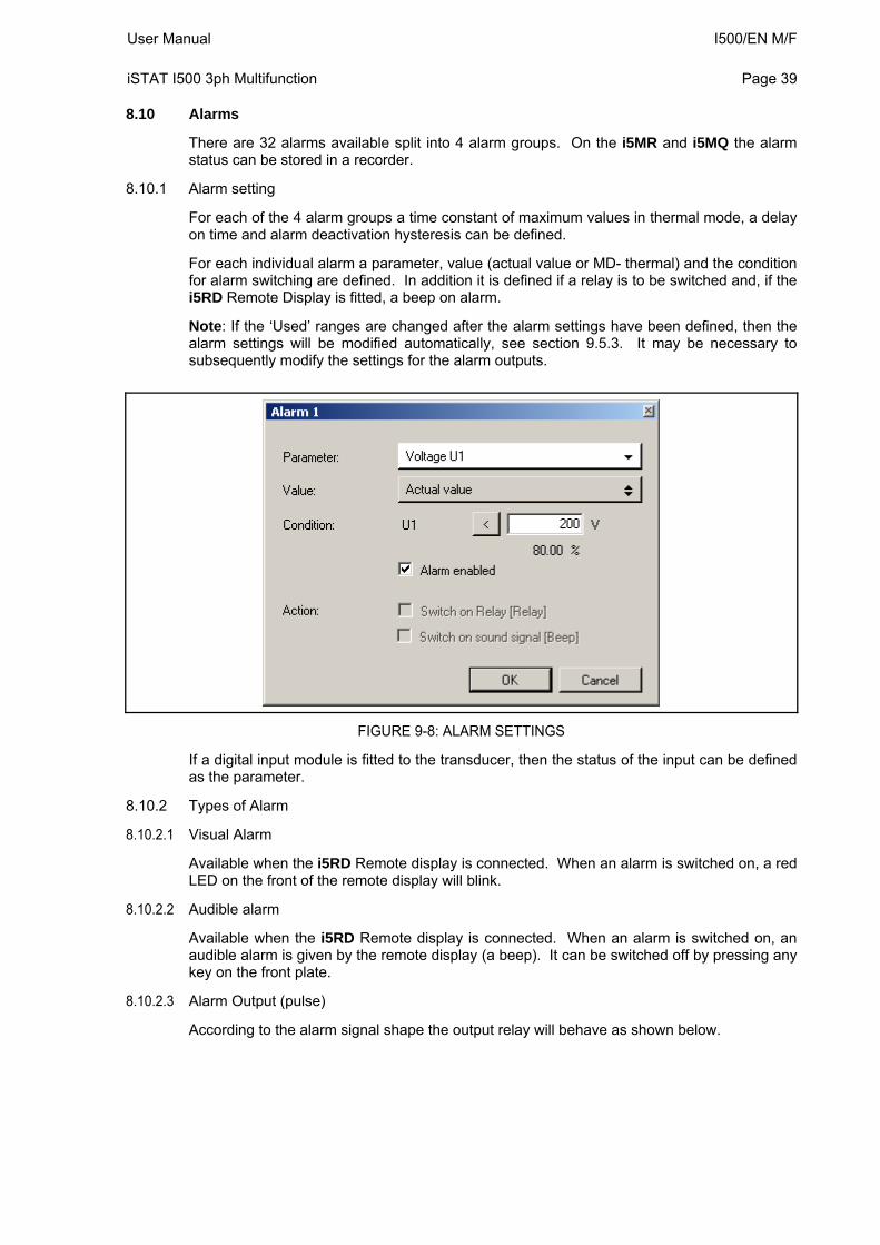
8.10.1 Alarm setting
For each of the 4 alarm groups a time constant of maximum values in thermal mode, a delay on time and alarm deactivation hysteresis can be defined.
For each individual alarm a parameter, value (actual value or MD- thermal) and the condition for alarm switching are defined. In addition it is defined if a relay is to be switched and, if the i5RD Remote Display is fitted, a beep on alarm.
Note: If the ‘Used’ ranges are changed after the alarm settings have been defined, then the alarm settings will be modified automatically, see section 9.5.3. It may be necessary to subsequently modify the settings for the alarm outputs.
FIGURE 9-8: ALARM SETTINGS
If a digital input module is fitted to the transducer, then the status of the input can be defined as the parameter.
8.10.2 Types of Alarm
8.10.2.1 Visual Alarm
Available when the i5RD Remote display is connected. When an alarm is switched on, a red LED on the front of the remote display will blink.
8.10.2.2 Audible alarm
Available when the i5RD Remote display is connected. When an alarm is switched on, an audible alarm is given by the remote display (a beep). It can be switched off by pressing any key on the front plate.
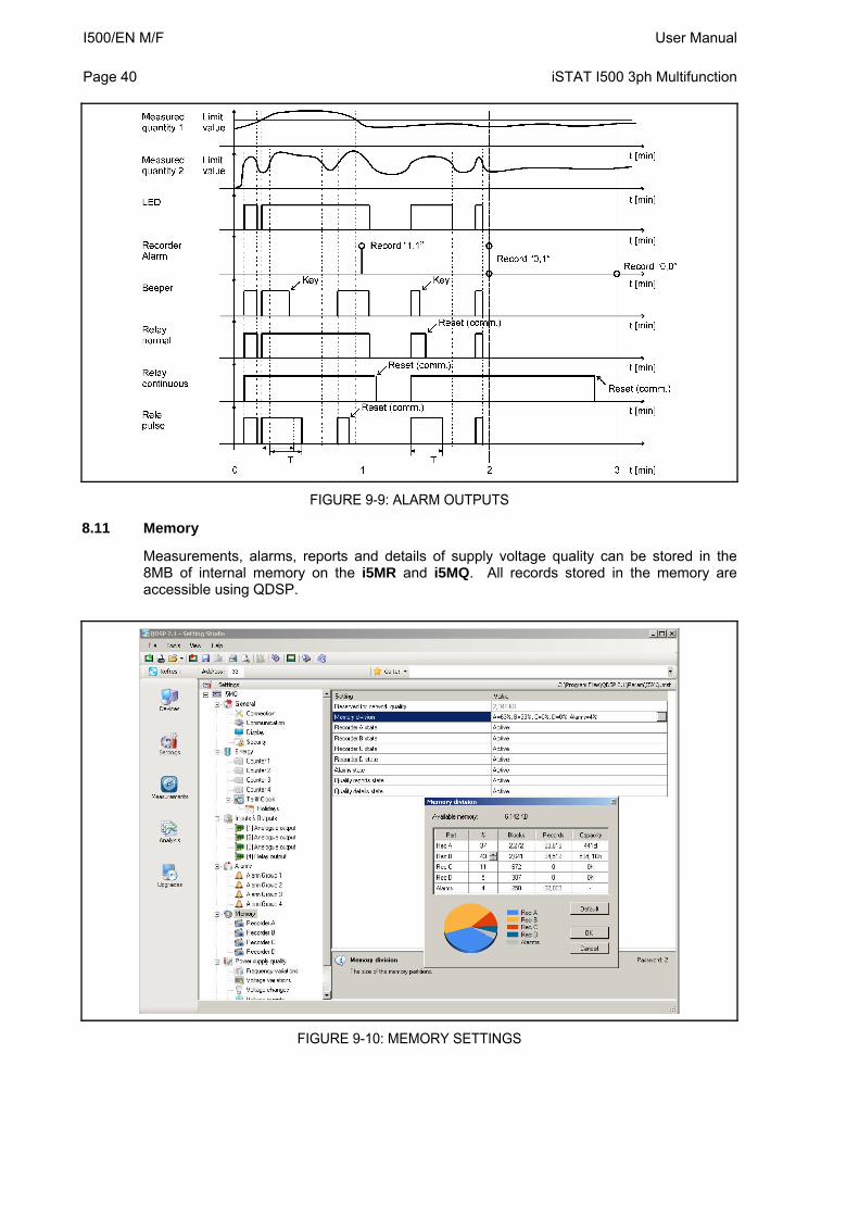
8.10.2.3 Alarm Output (pulse)
According to the alarm signal shape the output relay will behave as shown below.
I500/EN M/F User Manual Page 40
iSTAT I500 3ph Multifunction
FIGURE 9-9: ALARM OUTPUTS
8.11 Memory
Measurements, alarms, reports and details of supply voltage quality can be stored in the 8MB of internal memory on the i5MR and i5MQ. All records stored in the memory are accessible using QDSP.
FIGURE 9-10: MEMORY SETTINGS
User Manual I500/EN M/F iSTAT I500 3ph Multifunction
Page 41
8.11.1 Memory division
The internal memory is divided into up to 5 partitions, whose size can be defined by the customer, see Figure 9-10. The recorders are intended for recording measurements, while alarms are recorded in a separate partition. The i5MQ has 2 additional partitions for recording reports and details on the quality of supply voltage.
8.11.2 Memory clearing
There is usually no need to clear the memory as it works in cyclic mode in FIFO method with the oldest records being overwritten when new records are stored. If you need to clear memory then follow these steps:
Read the instrument readings with QDSP and set “Recorder state” in Memory to ‘stopped’.
Download the changes to the device and open Memory info form and then click on Clear memory button.
Select memory partitions to be cleared on Memory form and click OK.
Set “Recorder state” setting back to ‘Active’.
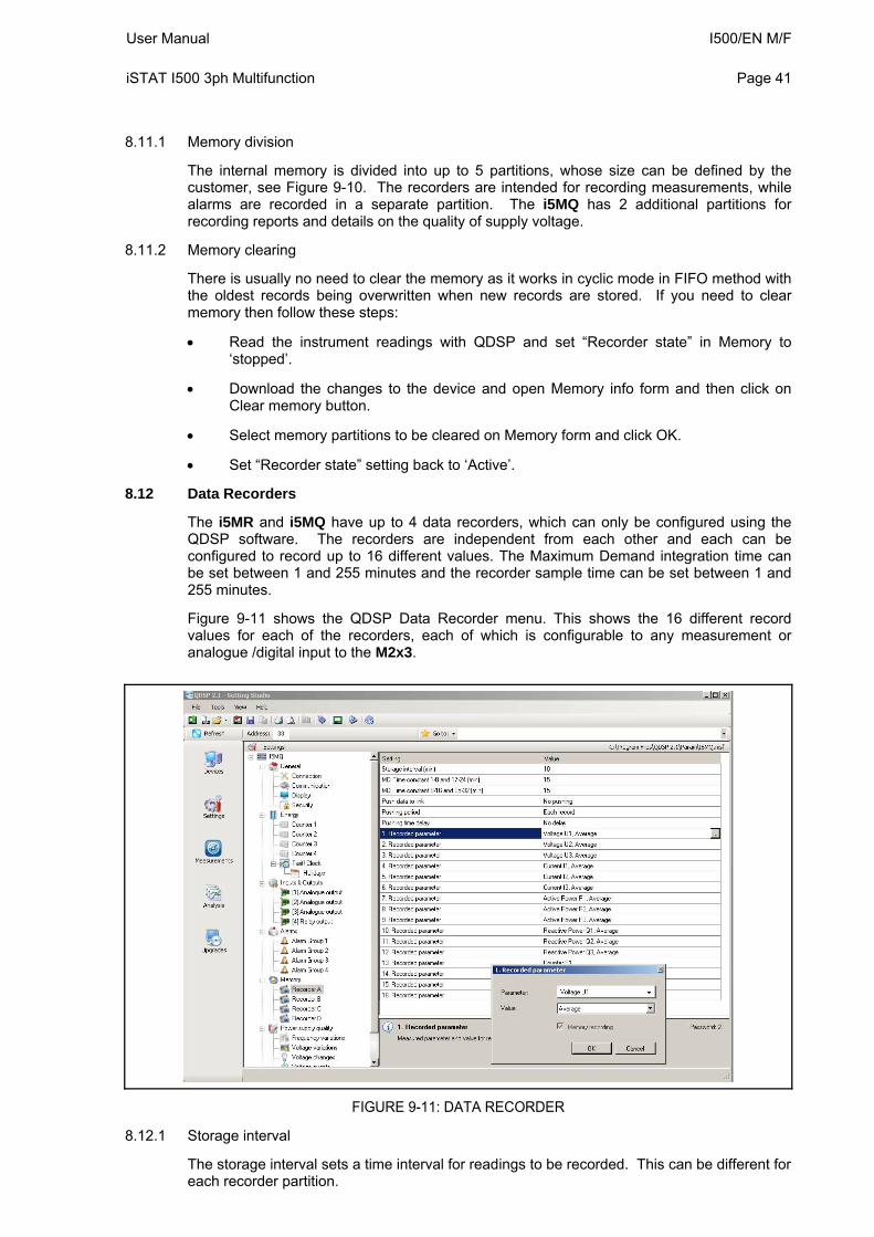
8.12 Data Recorders
The i5MR and i5MQ have up to 4 data recorders, which can only be configured using the QDSP software. The recorders are independent from each other and each can be configured to record up to 16 different values. The Maximum Demand integration time can be set between 1 and 255 minutes and the recorder sample time can be set between 1 and 255 minutes.
Figure 9-11 shows the QDSP Data Recorder menu. This shows the 16 different record values for each of the recorders, each of which is configurable to any measurement or analogue /digital input to the M2x3.
FIGURE 9-11: DATA RECORDER
8.12.1 Storage interval
The storage interval sets a time interval for readings to be recorded. This can be different for each recorder partition.
I500/EN M/F User Manual Page 42
iSTAT I500 3ph Multifunction
8.12.2 MD Time constant
When maximum demand values are to be recorded, this setting sets a period for calculation of maximum and minimum value in thermal mode (Minimum (MD) or Maximum (MD)). Different parameters can be set for Recorded parameters 1-8 and 9-16.
8.12.3 Recorded quantities
For each measurement to be recorded it is possible to set the required quantity and its type. Parameter The required monitoring quantity can be selected from a list of supported measurements. Besides the primary electrical quantities, auxiliary quantities from the input modules can also be selected. Value The type of the selected quantity to be recorded can be defined.
Minimum and Maximum value represents minimum or maximum of the recorded averaged values within the selected storage interval. Note that the minimum and maximum values are not single period values but an average (0.1 s to 5 s).
Minimum (MD) and Maximum (MD) value represents the calculation of a MD value with applied thermal function.
Average value represents the calculated average value within the selected storage interval
Actual value represents the first momentary value within the selected storage interval. Note that momentary values are not a single period value but an average (0.1 s to 5 s). (recommended for Pst and Plt measurements)
Minimum and Maximum (Period) values represent the minimum or maximum values within the selected storage interval calculated in a single period. This function allows recording of very fast changes.
8.13 Power Quality Recorder Report
The I5MQ has a power quality measurement function that monitors compliance to the European standard EN50160. The power quality features can be set on the i5MQ and this then determines what data is communicated.
The EN 50160 standard deals with voltage characteristics of electricity supplied by public distribution systems. This specifies the limits or values within which a customer can expect voltage characteristics to lie. Within this definition the i5MQ Network Analyser supervises the compliance of distribution systems with the EN 50160 standard.
Based on the requirements stated in the standard, default parameters are set in the meter according to which supervision of all required parameters is done. Parameters can also be changed in detailed setting of individual characteristics.
The i5MQ has 2MB of non-volatile memory reserved for storing power quality data with a capacity for storing 170,000 variations from standard.
The EN50160 standard monitors the following electrical characteristics:
Frequency and voltage variations
Voltage unbalances, interruptions and dips
Long and Transient (fast) interruptions
Flicker, short and long term
Individual Harmonics and %THD
All the Power Quality settings, extraction and tabulation of findings are done using the QDSP software.
User Manual I500/EN M/F iSTAT I500 3ph Multifunction
Page 43
The following definitions are used in Power Quality applications:
Un = nominal supply voltage for the electrical system
Uc = agreed supply voltage for the electrical system, this may be the same as Un.
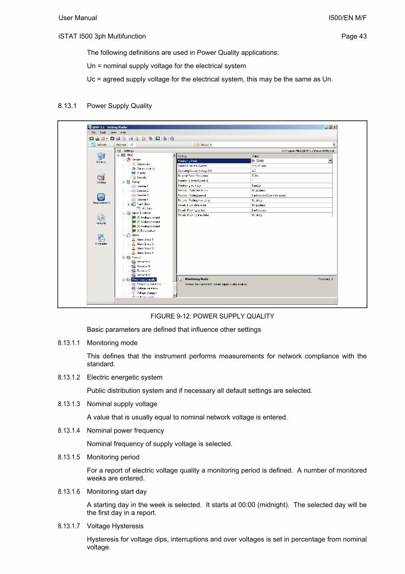
8.13.1 Power Supply Quality
FIGURE 9-12: POWER SUPPLY QUALITY
Basic parameters are defined that influence other settings
8.13.1.1 Monitoring mode
This defines that the instrument performs measurements for network compliance with the standard.
8.13.1.2 Electric energetic system
Public distribution system and if necessary all default settings are selected.
8.13.1.3 Nominal supply voltage
A value that is usually equal to nominal network voltage is entered.
8.13.1.4 Nominal power frequency
Nominal frequency of supply voltage is selected.
8.13.1.5 Monitoring period
For a report of electric voltage quality a monitoring period is defined. A number of monitored weeks are entered.
8.13.1.6 Monitoring start day
A starting day in the week is selected. It starts at 00:00 (midnight). The selected day will be the first day in a report.
8.13.1.7 Voltage Hysteresis
Hysteresis for voltage dips, interruptions and over voltages is set in percentage from nominal voltage.
I500/EN M/F User Manual Page 44
iSTAT I500 3ph Multifunction
8.13.2 Frequency Variations
All frequency measurements are performed in 10-second averaging intervals. There are two variation classes and for each a variation is defined as a percentage of nominal and also the percentage of measurements which have to be within the variation limits (required quality).
8.13.3 Voltage Variations
All Voltage measurements are performed in 10-second averaging intervals. There are two variation classes and for each a variation is defined as a percentage of nominal and also the percentage of measurements which have to be within the variation limits (required quality).
8.13.4 Dips and Interruptions
Limits for voltage dips and interruptions are defined as a percentage of the nominal voltage. A threshold between short-term and long-term interruptions is defined in seconds. And also the allowable number of dips and interruptions are defined by other parameters.
8.13.5 Rapid Voltage Changes
The limits and the number of allowable changes are defined.
8.13.6 Temporary overvoltages, flickers.
There are two types of flicker: short-term flicker intensity (Pst) and long-term flicker intensity (Plt) for each a monitoring period, performance limit and required signal quality are defined.
8.13.7 Harmonics and THD
The permitted limits for the first 25 harmonic components and the THD are defined with the required quality in the monitoring period.
8.13.8 Reseting quality parameter reports
Some quality parameter reports are made on a weekly basis and other on yearly basis. The parameter reports are reset at the end of each observed period. Weekly based reports will be reset every week. Even if the instruments’ location or mode of operation is altered, the weekly report will reset at the end of the week. But yearly reports will not be reset until the end of the year. Therefore when required the yearly reports must be reset manually.
In order to reset reports choose setting <Power supply quality>< Monitoring mode> and change the value to “No monitoring”. Download settings to instrument. Then choose the same setting and change the value back to “EN50160”. Again download the settings to the instrument. Then all yearly reports (anomaly counters) will have been reset.
8.14 Reset Operations
8.14.1 Reset Min/Max values (RD)
All Min/Max values are reset.
8.14.2 Set energy counters (RD)
All or individual energy counters are reset.
8.14.3 Reset Energy counter costs (RD)
All or individual energy costs are reset.
8.14.4 Reset maximal MD values (RD)
8.14.4.1 Thermal mode
Current and stored MD’s are reset.
8.14.4.2 Fixed Interval / Sliding Window
The values in the current time interval, in all sub-windows and stored MD are reset. At the same time, synchronization of the time interval to the beginning of the first sub-window is also performed.
User Manual I500/EN M/F iSTAT I500 3ph Multifunction
Page 45
8.14.5 Reset the last MD period (RD)
8.14.5.1 Thermal mode
Current MD value is reset.
8.14.5.2 Fixed interval / Sliding windows
Values in the current time interval and in all sub-windows for sliding windows are reset. In the same time, synchronization of the time interval is also performed.
8.14.6 MD synchronization (RD)
8.14.6.1 Thermal mode
In this mode, synchronization does not have any influence.
8.14.6.2 Fixed interval / Sliding Windows
Synchronisation sets time in a period or a sub-period for sliding windows to 0 (zero). If the interval is set to 2, 3, 4, 5, 6, 10, 12, 15, 20, 30 or 60 minutes, time set in a period is set to such a value that some intervals will be terminated at completed hour.
Example:
Time constant (interval) 15 min 10 min 7 min
Synchronization start time 10:42 10:42 10:42
Time in a period 12 min 2 min 0 min
First final interval 10:45 10:50 10:49
8.14.7 Reset alarm output (RD)
All alarm outputs are reset.
I500/EN M/F User Manual Page 46
iSTAT I500 3ph Multifunction
9. SYSTEM MODES
9.1 Connection mode
The connection mode of the I500 is configurable. The following options are available:
1b - single phase connection,
3b - three-phase, three-wire connection with balanced load,
4b - three-phase, four-wire connection with balanced load,
3u - three-phase, three-wire connection with unbalanced load
4u - three-phase, four-wire connection with unbalanced load.
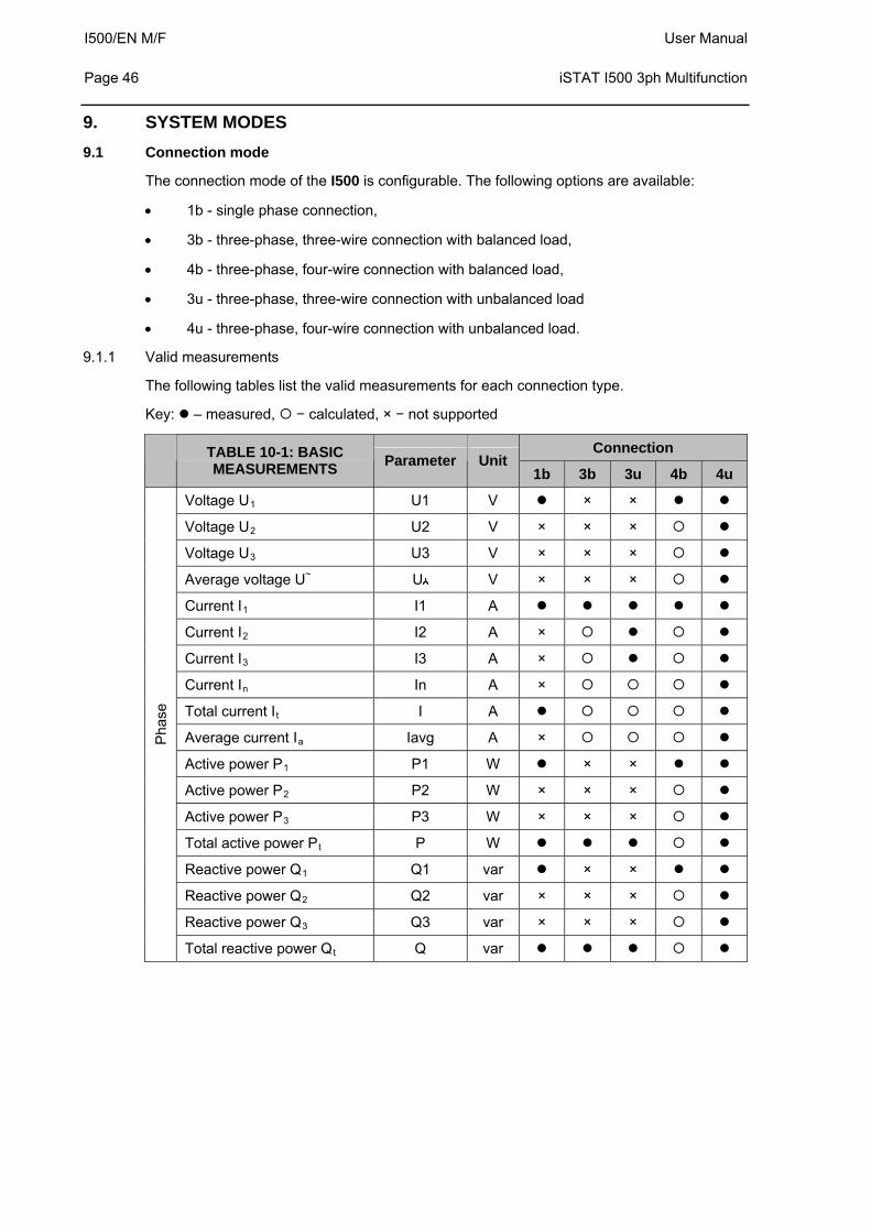
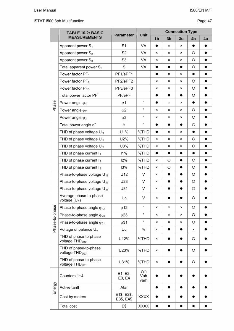
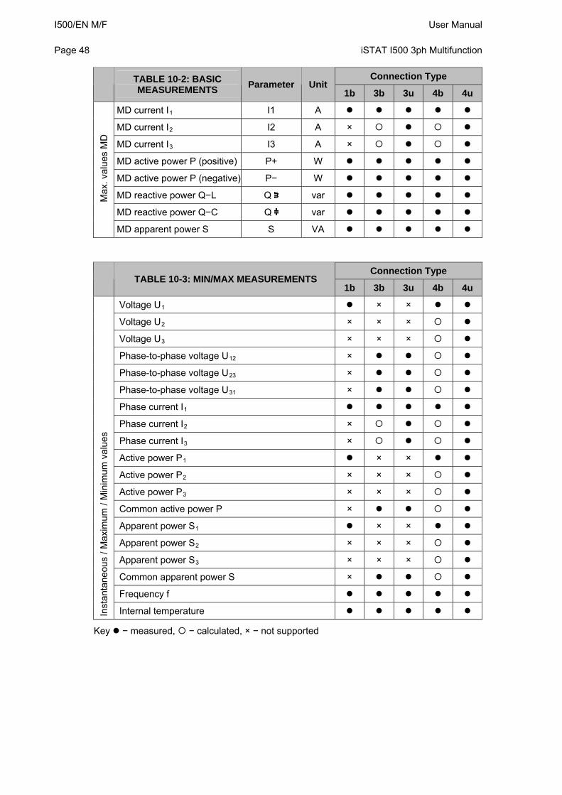
9.1.1 Valid measurements
The following tables list the valid measurements for each connection type.
Key: – measured, − calculated, × − not supported
Connection TABLE 10-1: BASIC MEASUREMENTS
Parameter Unit 1b 3b 3u 4b 4u
Voltage U1 U1 V × ×
Voltage U2 U2 V × × ×
Voltage U3 U3 V × × ×
Average voltage U~ U V × × ×
Current I1 I1 A
Current I2 I2 A ×
Current I3 I3 A ×
Current In In A ×
Total current It I A
Average current Ia Iavg A ×
Active power P1 P1 W × ×
Active power P2 P2 W × × ×
Active power P3 P3 W × × ×
Total active power Pt P W
Reactive power Q1 Q1 var × ×
Reactive power Q2 Q2 var × × ×
Reactive power Q3 Q3 var × × ×
Pha
se
Total reactive power Qt Q var
User Manual I500/EN M/F iSTAT I500 3ph Multifunction
Page 47
Connection Type TABLE 10-2: BASIC MEASUREMENTS
Parameter Unit 1b 3b 3u 4b 4u
Apparent power S1 S1 VA × ×
Apparent power S2 S2 VA × × ×
Apparent power S3 S3 VA × × ×
Total apparent power St S VA
Power factor PF1 PF1/ePF1 × ×
Power factor PF2 PF2/ePF2 × × ×
Power factor PF3 PF3/ePF3 × × ×
Total power factor PF~ PF/ePF
Power angle 1 1 ° × ×
Power angle 2 2 ° × × ×
Power angle 3 3 ° × × ×
Total power angle ~ °
THD of phase voltage Uf1 U1% %THD × ×
THD of phase voltage Uf2 U2% %THD × × ×
THD of phase voltage Uf3 U3% %THD × × ×
THD of phase current I1 I1% %THD
THD of phase current I2 I2% %THD ×
Pha
se
THD of phase current I3 I3% %THD ×
Phase-to-phase voltage U12 U12 V ×
Phase-to-phase voltage U23 U23 V ×
Phase-to-phase voltage U31 U31 V ×
Average phase-to-phase voltage (Uff)
U V ×
Phase-to-phase angle 12 12 ° × × ×
Phase-to-phase angle 23 23 ° × × ×
Phase-to-phase angle 31 31 ° × × ×
Voltage unbalance Uu Uu % × ×
THD of phase-to-phase voltage THDU12
U12% %THD ×
THD of phase-to-phase voltage THDU23
U23% %THD ×
Pha
se-t
o-ph
ase
THD of phase-to-phase voltage THDU31
U31% %THD ×
Counters 1−4 E1, E2, E3, E4
Wh Vahvarh
Active tariff Atar
Cost by meters E1$, E2$, E3$, E4$
XXXX
Ene
rgy
Total cost E$ XXXX
I500/EN M/F User Manual Page 48
iSTAT I500 3ph Multifunction
Connection Type TABLE 10-2: BASIC Parameter Unit
MEASUREMENTS 1b 3b 3u 4b 4u
MD current I1 I1 A
MD current I2 I2 A ×
MD current I3 I3 A ×
MD active power P (positive) P+ W
MD active power P (negative) P− W
MD reactive power Q−L Q var
MD reactive power Q−C Q var
Max
. val
ues
MD
MD apparent power S S VA
Connection Type TABLE 10-3: MIN/MAX MEASUREMENTS
1b 3b 3u 4b 4u
Voltage U1 × ×
Voltage U2 × × ×
Voltage U3 × × ×
Phase-to-phase voltage U12 ×
Phase-to-phase voltage U23 ×
Phase-to-phase voltage U31 ×
Phase current I1
Phase current I2 ×
Phase current I3 ×
Active power P1 × ×
Active power P2 × × ×
Active power P3 × × ×
Common active power P ×
Apparent power S1 × ×
Apparent power S2 × × ×
Apparent power S3 × × ×
Common apparent power S ×
Frequency f
Inst
anta
neou
s / M
axim
um /
Min
imum
val
ues
Internal temperature
Key − measured, − calculated, × − not supported
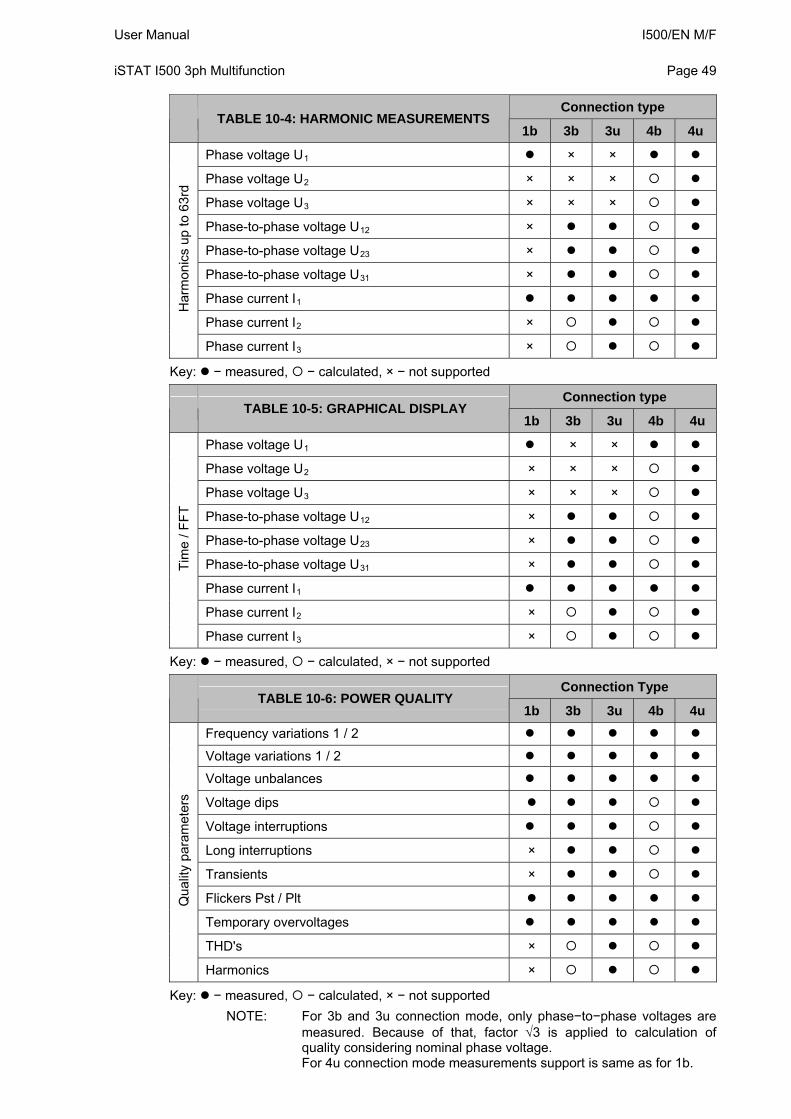
User Manual I500/EN M/F iSTAT I500 3ph Multifunction
Page 49
Connection type TABLE 10-4: HARMONIC MEASUREMENTS
1b 3b 3u 4b 4u
Phase voltage U1 × ×
Phase voltage U2 × × ×
Phase voltage U3 × × ×
Phase-to-phase voltage U12 ×
Phase-to-phase voltage U23 ×
Phase-to-phase voltage U31 ×
Phase current I1
Phase current I2 ×
Har
mon
ics
up to
63r
d
Phase current I3 ×
Key: − measured, − calculated, × − not supported
Connection type TABLE 10-5: GRAPHICAL DISPLAY
1b 3b 3u 4b 4u
Phase voltage U1 × ×
Phase voltage U2 × × ×
Phase voltage U3 × × ×
Phase-to-phase voltage U12 ×
Phase-to-phase voltage U23 ×
Phase-to-phase voltage U31 ×
Phase current I1
Phase current I2 ×
Tim
e / F
FT
Phase current I3 ×
Key: − measured, − calculated, × − not supported
Connection Type TABLE 10-6: POWER QUALITY
1b 3b 3u 4b 4u
Frequency variations 1 / 2
Voltage variations 1 / 2
Voltage unbalances
Voltage dips
Voltage interruptions
Long interruptions ×
Transients ×
Flickers Pst / Plt
Temporary overvoltages
THD's ×
Qua
lity
para
met
ers
Harmonics ×
Key: − measured, − calculated, × − not supported
NOTE: For 3b and 3u connection mode, only phase−to−phase voltages are measured. Because of that, factor 3 is applied to calculation of quality considering nominal phase voltage. For 4u connection mode measurements support is same as for 1b.
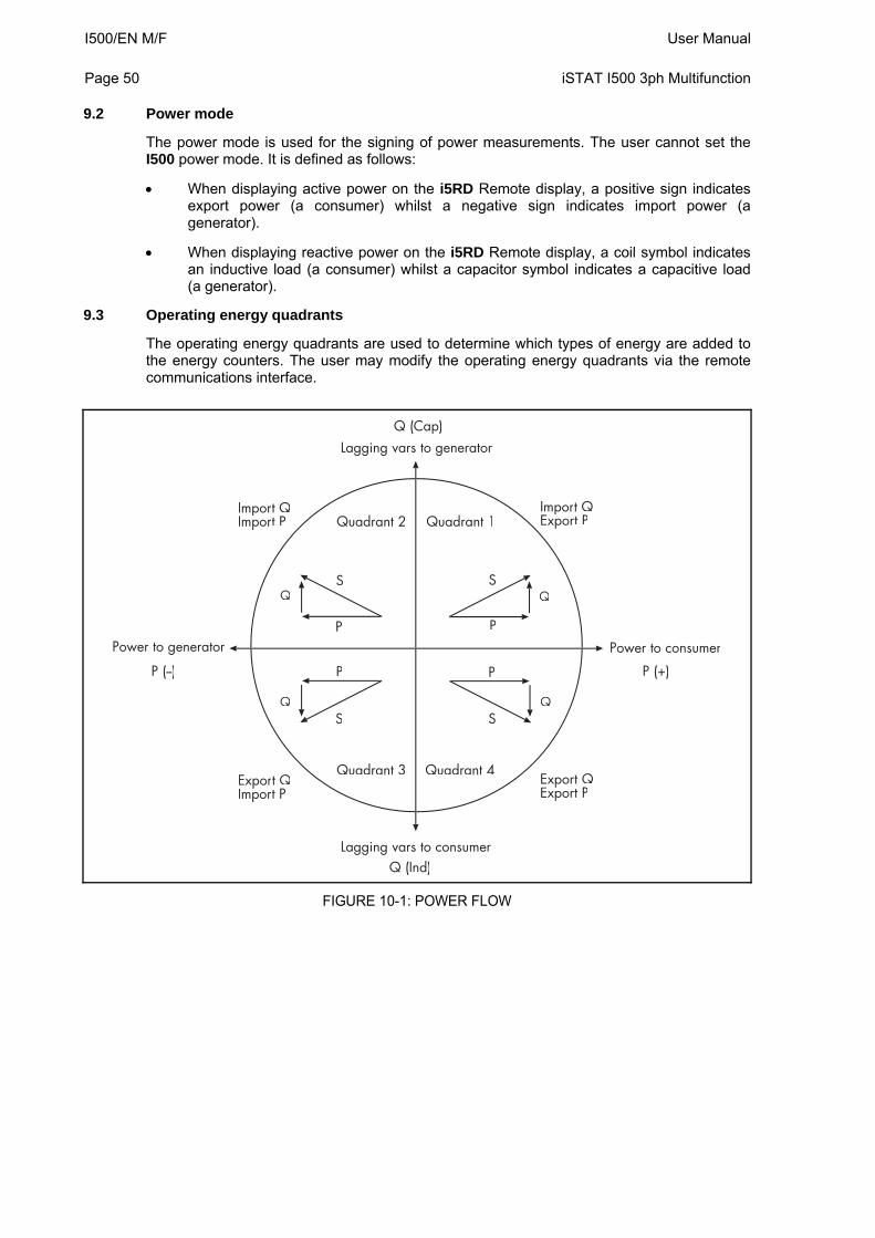
I500/EN M/F User Manual Page 50
iSTAT I500 3ph Multifunction
9.2 Power mode
The power mode is used for the signing of power measurements. The user cannot set the I500 power mode. It is defined as follows:
When displaying active power on the i5RD Remote display, a positive sign indicates export power (a consumer) whilst a negative sign indicates import power (a generator).
When displaying reactive power on the i5RD Remote display, a coil symbol indicates an inductive load (a consumer) whilst a capacitor symbol indicates a capacitive load (a generator).
9.3 Operating energy quadrants
The operating energy quadrants are used to determine which types of energy are added to the energy counters. The user may modify the operating energy quadrants via the remote communications interface.
S
SS
S
P P
PP
Q
Q
Q
Q
Quadrant 2 Quadrant 1
Quadrant 3 Quadrant 4
Import QImpor
pt P
Import QExpor
pt P
Export QExpor
pt P
Export QImpor
pt P
Lagging vars to generator
Lagging vars to consumer
Power to consumerPower to generator
Q (Cap)
Q (Ind)
P (--) P (+)
FIGURE 10-1: POWER FLOW
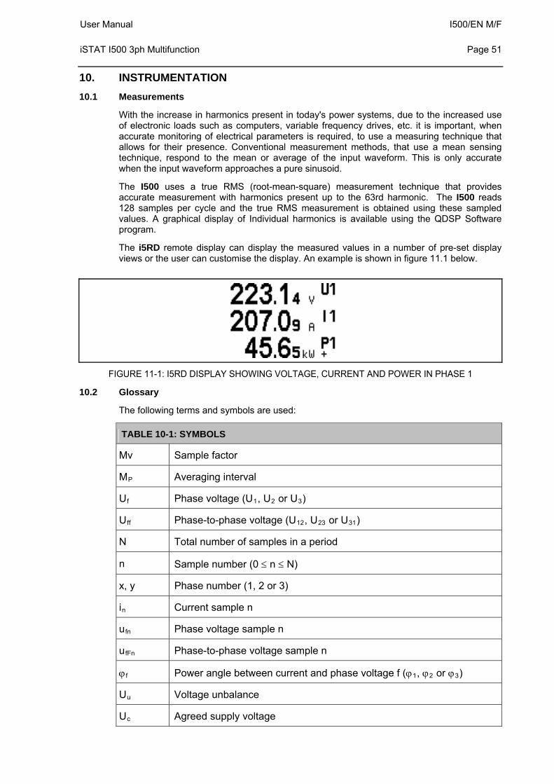
User Manual I500/EN M/F iSTAT I500 3ph Multifunction
Page 51
10. INSTRUMENTATION
10.1 Measurements
With the increase in harmonics present in today's power systems, due to the increased use of electronic loads such as computers, variable frequency drives, etc. it is important, when accurate monitoring of electrical parameters is required, to use a measuring technique that allows for their presence. Conventional measurement methods, that use a mean sensing technique, respond to the mean or average of the input waveform. This is only accurate when the input waveform approaches a pure sinusoid.
The I500 uses a true RMS (root-mean-square) measurement technique that provides accurate measurement with harmonics present up to the 63rd harmonic. The I500 reads 128 samples per cycle and the true RMS measurement is obtained using these sampled values. A graphical display of Individual harmonics is available using the QDSP Software program.
The i5RD remote display can display the measured values in a number of pre-set display views or the user can customise the display. An example is shown in figure 11.1 below.
FIGURE 11-1: I5RD DISPLAY SHOWING VOLTAGE, CURRENT AND POWER IN PHASE 1
10.2 Glossary
The following terms and symbols are used:
TABLE 10-1: SYMBOLS
Mv Sample factor
MP Averaging interval
Uf Phase voltage (U1, U2 or U3)
Uff Phase-to-phase voltage (U12, U23 or U31)
N Total number of samples in a period
n Sample number (0 n N)
x, y Phase number (1, 2 or 3)
in Current sample n
ufn Phase voltage sample n
ufFn Phase-to-phase voltage sample n
f Power angle between current and phase voltage f (1, 2 or 3)
Uu Voltage unbalance
Uc Agreed supply voltage
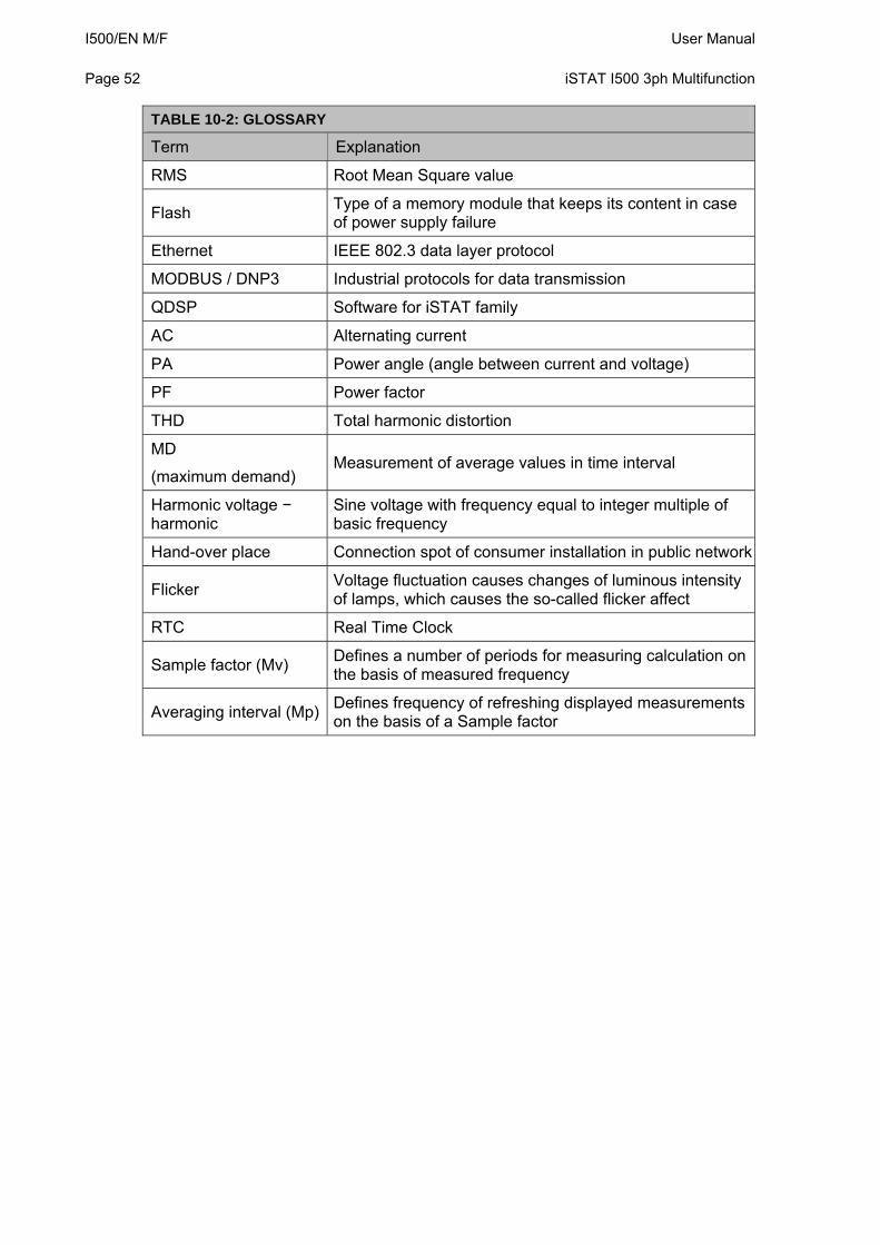
I500/EN M/F User Manual Page 52
iSTAT I500 3ph Multifunction
TABLE 10-2: GLOSSARY
Term Explanation
RMS Root Mean Square value
Flash Type of a memory module that keeps its content in case of power supply failure
Ethernet IEEE 802.3 data layer protocol
MODBUS / DNP3 Industrial protocols for data transmission
QDSP Software for iSTAT family
AC Alternating current
PA Power angle (angle between current and voltage)
PF Power factor
THD Total harmonic distortion
MD
(maximum demand) Measurement of average values in time interval
Harmonic voltage − harmonic
Sine voltage with frequency equal to integer multiple of basic frequency
Hand-over place Connection spot of consumer installation in public network
Flicker Voltage fluctuation causes changes of luminous intensity of lamps, which causes the so-called flicker affect
RTC Real Time Clock
Sample factor (Mv) Defines a number of periods for measuring calculation on the basis of measured frequency
Averaging interval (Mp) Defines frequency of refreshing displayed measurements on the basis of a Sample factor
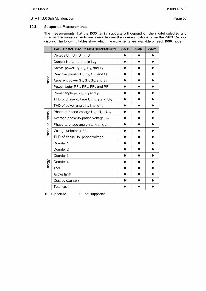
User Manual I500/EN M/F iSTAT I500 3ph Multifunction
Page 53
10.3 Supported Measurements
The measurements that the I500 family supports will depend on the model selected and whether the measurements are available over the communications or on the i5RD Remote display. The following tables show which measurements are available on each I500 model.
TABLE 10-3: BASIC MEASUREMENTS i5MT i5MR i5MQ
Voltage U1, U2, U3 in U~
Current I1, I2, I3, In, It in Iavg
Active power P1, P2, P3, and Pt
Reactive power Q1, Q2, Q3, and Qt
Apparent power S1, S2, S3, and St
Power factor PF1, PF2, PF3 and PF~
Power angle 1, 2, 3 and ~
THD of phase voltage Uf1, Uf2 and Uf3
Pha
se
THD of power angle I1, I2 and I3
Phase-to-phase voltage U12, U23, U31
Average phase-to-phase voltage Uff
Phase-to-phase angle 12, 23, 31
Voltage unbalance Uu
Pha
se−
to−
phas
e
THD of phase−to−phase voltage
Counter 1
Counter 2
Counter 3
Counter 4
Total
Active tariff
Cost by counters
Ene
rgy
Total cost
− supported × − not supported
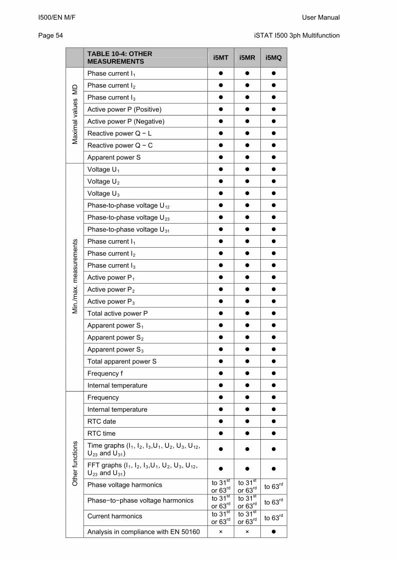
I500/EN M/F User Manual Page 54
iSTAT I500 3ph Multifunction
TABLE 10-4: OTHER MEASUREMENTS
i5MT i5MR i5MQ
Phase current I1
Phase current I2
Phase current I3
Active power P (Positive)
Active power P (Negative)
Reactive power Q − L
Reactive power Q − C Max
imal
val
ues
MD
Apparent power S
Voltage U1
Voltage U2
Voltage U3
Phase-to-phase voltage U12
Phase-to-phase voltage U23
Phase-to-phase voltage U31
Phase current I1
Phase current I2
Phase current I3
Active power P1
Active power P2
Active power P3
Total active power P
Apparent power S1
Apparent power S2
Apparent power S3
Total apparent power S
Frequency f
Min
./max
. mea
sure
men
ts
Internal temperature
Frequency
Internal temperature
RTC date
RTC time
Time graphs (I1, I2, I3,U1, U2, U3, U12, U23 and U31)
FFT graphs (I1, I2, I3,U1, U2, U3, U12, U23 and U31)
Phase voltage harmonics to 31st or 63rd
to 31st or 63rd
to 63rd
Phase−to−phase voltage harmonics to 31st or 63rd
to 31st or 63rd
to 63rd
Current harmonics to 31st or 63rd
to 31st or 63rd
to 63rd
Oth
er fu
nctio
ns
Analysis in compliance with EN 50160 × ×
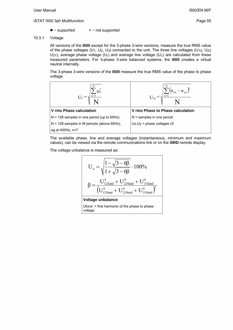
User Manual I500/EN M/F iSTAT I500 3ph Multifunction
Page 55
− supported × − not supported
10.3.1 Voltage
All versions of the I500 except for the 3-phase 3-wire versions, measure the true RMS value of the phase voltages (U1, U2, U3) connected to the unit. The three line voltages (U12, U23 U31), average phase voltage (Uf) and average line voltage (U) are calculated from these measured parameters. For 3-phase 3-wire balanced systems, the I500 creates a virtual neutral internally.
The 3-phase 3-wire versions of the I500 measure the true RMS value of the phase to phase voltage.
N
u = U
2n
N
1=nf
N
2ynxn
N
1=nxy
uu = U
V rms Phase calculation
N = 128 samples in one period (up to 65Hz)
N = 128 samples in M periods (above 65Hz),
eg at 400Hz, n=7
V rms Phase to Phase calculation
N = samples in one period
Ux,Uy = phase voltages Uf
The available phase, line and average voltages (instantaneous, minimum and maximum values), can be viewed via the remote communications link or on the i5RD remote display.
The voltage unbalance is measured as:
24fund31
4fund23
4fund12
4fund31
4fund23
4fund12
u
UUU
UUU
%100631
631U
Voltage unbalance
Ufund = first harmonic of the phase to phase voltage
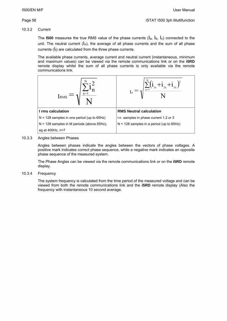
I500/EN M/F User Manual Page 56
iSTAT I500 3ph Multifunction
10.3.2 Current
The I500 measures the true RMS value of the phase currents (Ia, Ib, Ic) connected to the
unit. The neutral current (In), the average of all phase currents and the sum of all phase
currents (It) are calculated from the three phase currents.
The available phase currents, average current and neutral current (instantaneous, minimum and maximum values) can be viewed via the remote communications link or on the i5RD remote display whilst the sum of all phase currents is only available via the remote communications link.
N
i =
2n
I
N
1=nRMS
N
iii =
2
n3n2n1
N
1=nnI
I rms calculation
N = 128 samples in one period (up to 65Hz)
N = 128 samples in M periods (above 65Hz),
eg at 400Hz, n=7
RMS Neutral calculation
i-n samples in phase current 1,2 or 3
N = 128 samples in a period (up to 65Hz)
10.3.3 Angles between Phases
Angles between phases indicate the angles between the vectors of phase voltages. A positive mark indicates correct phase sequence, while a negative mark indicates an opposite phase sequence of the measured system.
The Phase Angles can be viewed via the remote communications link or on the i5RD remote display.
10.3.4 Frequency
The system frequency is calculated from the time period of the measured voltage and can be viewed from both the remote communications link and the i5RD remote display (Also the frequency with instantaneous 10 second average.
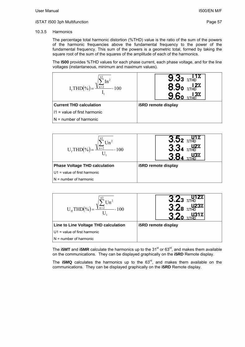
User Manual I500/EN M/F iSTAT I500 3ph Multifunction
Page 57
10.3.5 Harmonics
The percentage total harmonic distortion (%THD) value is the ratio of the sum of the powers of the harmonic frequencies above the fundamental frequency to the power of the fundamental frequency. This sum of the powers is a geometric total, formed by taking the square root of the sum of the squares of the amplitude of each of the harmonics.
The I500 provides %THD values for each phase current, each phase voltage, and for the line voltages (instantaneous, minimum and maximum values).
100I
In
%THDI1
63
2n
2
f
Current THD calculation
I1 = value of first harmonic
N = number of harmonic
i5RD remote display
100U
Un
%THDU1
63
2n
2
f
Phase Voltage THD calculation
U1 = value of first harmonic
N = number of harmonic
i5RD remote display
100U
Un
%THDU1
63
2n
2
ff
Line to Line Voltage THD calculation
U1 = value of first harmonic
N = number of harmonic
i5RD remote display
The i5MT and i5MR calculate the harmonics up to the 31st or 63rd, and makes them available on the communications. They can be displayed graphically on the i5RD Remote display.
The i5MQ calculates the harmonics up to the 63rd, and makes them available on the communications. They can be displayed graphically on the i5RD Remote display.
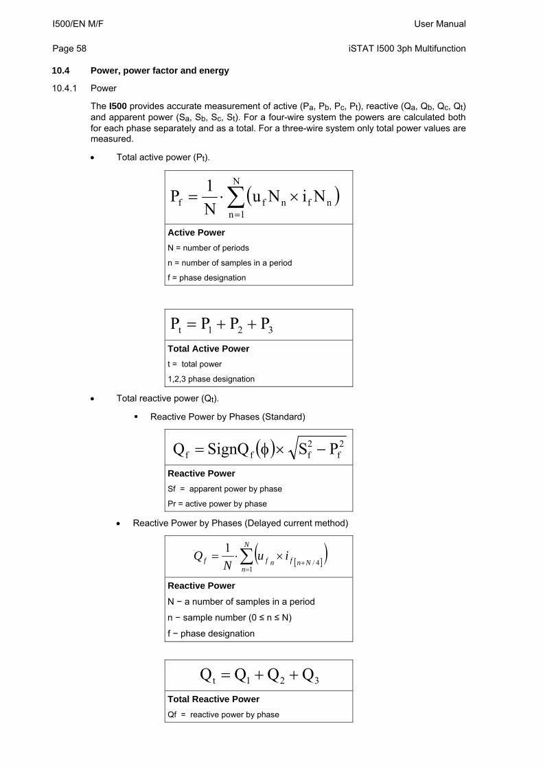
I500/EN M/F User Manual Page 58
iSTAT I500 3ph Multifunction
10.4 Power, power factor and energy
10.4.1 Power
The I500 provides accurate measurement of active (Pa, Pb, Pc, Pt), reactive (Qa, Qb, Qc, Qt) and apparent power (Sa, Sb, Sc, St). For a four-wire system the powers are calculated both for each phase separately and as a total. For a three-wire system only total power values are measured.
Total active power (Pt).
N
1nnfnff NiNu
N
1P
Active Power
N = number of periods
n = number of samples in a period
f = phase designation
321t PPPP
Total Active Power
t = total power
1,2,3 phase designation
Total reactive power (Qt).
Reactive Power by Phases (Standard)
2f
2fff PSSignQQ
Reactive Power
Sf = apparent power by phase
Pr = active power by phase
Reactive Power by Phases (Delayed current method)
N
nNnfnff iu
NQ
14/
1
Reactive Power
N − a number of samples in a period
n − sample number (0 ≤ n ≤ N)
f − phase designation
321t QQQQ
Total Reactive Power
Qf = reactive power by phase
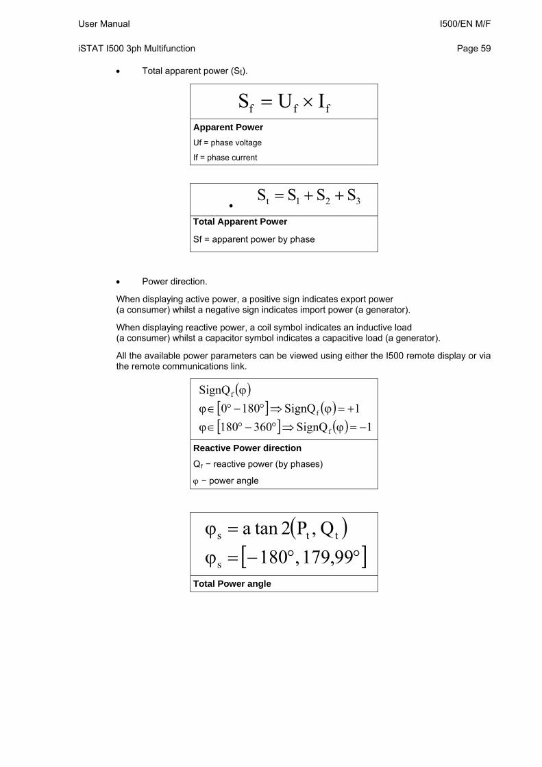
User Manual I500/EN M/F iSTAT I500 3ph Multifunction
Page 59
Total apparent power (St).
fff IUS
Apparent Power
Uf = phase voltage
If = phase current
321t SSSS
Total Apparent Power
Sf = apparent power by phase
Power direction.
When displaying active power, a positive sign indicates export power (a consumer) whilst a negative sign indicates import power (a generator).
When displaying reactive power, a coil symbol indicates an inductive load (a consumer) whilst a capacitor symbol indicates a capacitive load (a generator).
All the available power parameters can be viewed using either the I500 remote display or via the remote communications link.
1SignQ360801
1SignQ1800
SignQ
f
f
f
Reactive Power direction
Qf − reactive power (by phases)
− power angle
99,179,180
Q,P2tana
s
tts
Total Power angle
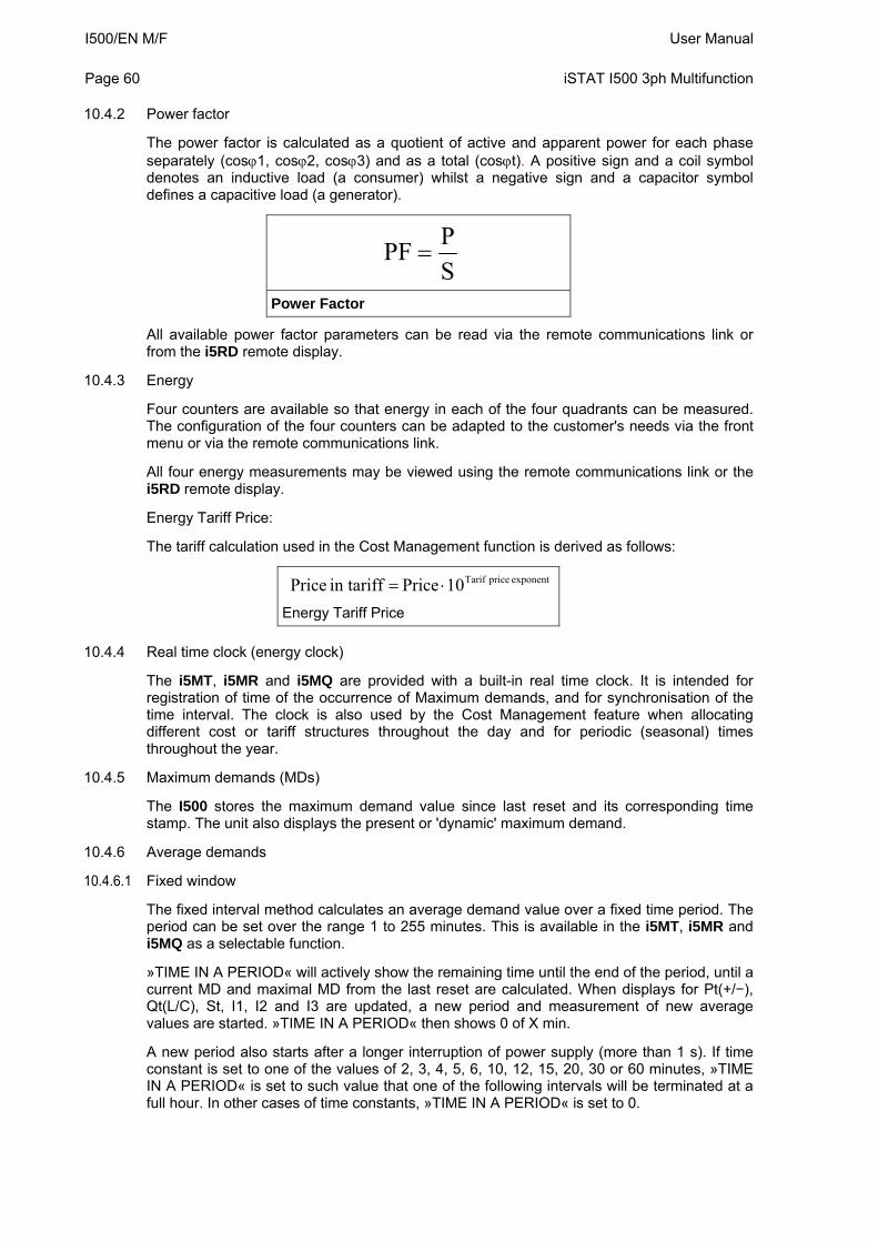
I500/EN M/F User Manual Page 60
iSTAT I500 3ph Multifunction
10.4.2 Power factor
The power factor is calculated as a quotient of active and apparent power for each phase separately (cos1, cos2, cos3) and as a total (cost). A positive sign and a coil symbol denotes an inductive load (a consumer) whilst a negative sign and a capacitor symbol defines a capacitive load (a generator).
S
PPF
Power Factor
All available power factor parameters can be read via the remote communications link or from the i5RD remote display.
10.4.3 Energy
Four counters are available so that energy in each of the four quadrants can be measured. The configuration of the four counters can be adapted to the customer's needs via the front menu or via the remote communications link.
All four energy measurements may be viewed using the remote communications link or the i5RD remote display.
Energy Tariff Price:
The tariff calculation used in the Cost Management function is derived as follows:
exponent price Tarif10 Price in tariff Price Energy Tariff Price
10.4.4 Real time clock (energy clock)
The i5MT, i5MR and i5MQ are provided with a built-in real time clock. It is intended for registration of time of the occurrence of Maximum demands, and for synchronisation of the time interval. The clock is also used by the Cost Management feature when allocating different cost or tariff structures throughout the day and for periodic (seasonal) times throughout the year.
10.4.5 Maximum demands (MDs)
The I500 stores the maximum demand value since last reset and its corresponding time stamp. The unit also displays the present or 'dynamic' maximum demand.
10.4.6 Average demands
10.4.6.1 Fixed window
The fixed interval method calculates an average demand value over a fixed time period. The period can be set over the range 1 to 255 minutes. This is available in the i5MT, i5MR and i5MQ as a selectable function.
»TIME IN A PERIOD« will actively show the remaining time until the end of the period, until a current MD and maximal MD from the last reset are calculated. When displays for Pt(+/−), Qt(L/C), St, I1, I2 and I3 are updated, a new period and measurement of new average values are started. »TIME IN A PERIOD« then shows 0 of X min.
A new period also starts after a longer interruption of power supply (more than 1 s). If time constant is set to one of the values of 2, 3, 4, 5, 6, 10, 12, 15, 20, 30 or 60 minutes, »TIME IN A PERIOD« is set to such value that one of the following intervals will be terminated at a full hour. In other cases of time constants, »TIME IN A PERIOD« is set to 0.
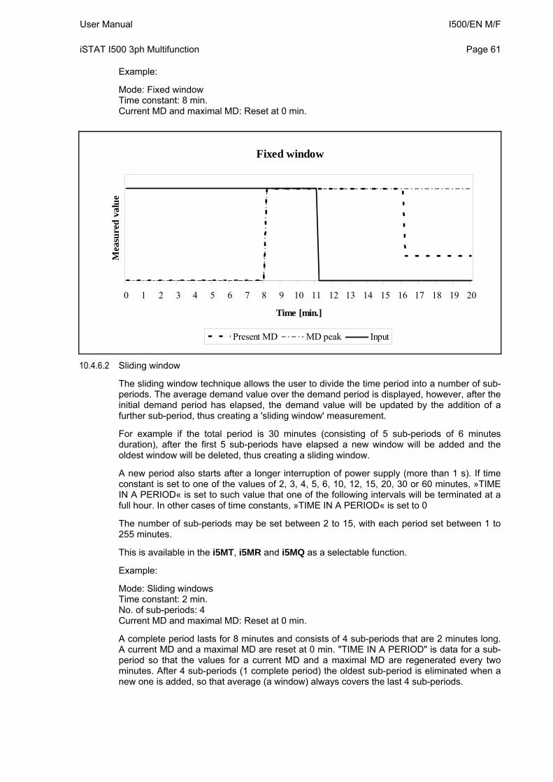
User Manual I500/EN M/F iSTAT I500 3ph Multifunction
Page 61
Example:
Mode: Fixed window Time constant: 8 min. Current MD and maximal MD: Reset at 0 min.
Fixed window
0 1 2 3 4 5 6 7 8 9 10 11 12 13 14 15 16 17 18 19 20
Time [min.]
Mea
sure
d v
alu
e
Present MD MD peak Input
10.4.6.2 Sliding window
The sliding window technique allows the user to divide the time period into a number of sub-periods. The average demand value over the demand period is displayed, however, after the initial demand period has elapsed, the demand value will be updated by the addition of a further sub-period, thus creating a 'sliding window' measurement.
For example if the total period is 30 minutes (consisting of 5 sub-periods of 6 minutes duration), after the first 5 sub-periods have elapsed a new window will be added and the oldest window will be deleted, thus creating a sliding window.
A new period also starts after a longer interruption of power supply (more than 1 s). If time constant is set to one of the values of 2, 3, 4, 5, 6, 10, 12, 15, 20, 30 or 60 minutes, »TIME IN A PERIOD« is set to such value that one of the following intervals will be terminated at a full hour. In other cases of time constants, »TIME IN A PERIOD« is set to 0
The number of sub-periods may be set between 2 to 15, with each period set between 1 to 255 minutes.
This is available in the i5MT, i5MR and i5MQ as a selectable function.
Example:
Mode: Sliding windows Time constant: 2 min. No. of sub-periods: 4 Current MD and maximal MD: Reset at 0 min.
A complete period lasts for 8 minutes and consists of 4 sub-periods that are 2 minutes long. A current MD and a maximal MD are reset at 0 min. "TIME IN A PERIOD" is data for a sub-period so that the values for a current MD and a maximal MD are regenerated every two minutes. After 4 sub-periods (1 complete period) the oldest sub-period is eliminated when a new one is added, so that average (a window) always covers the last 4 sub-periods.
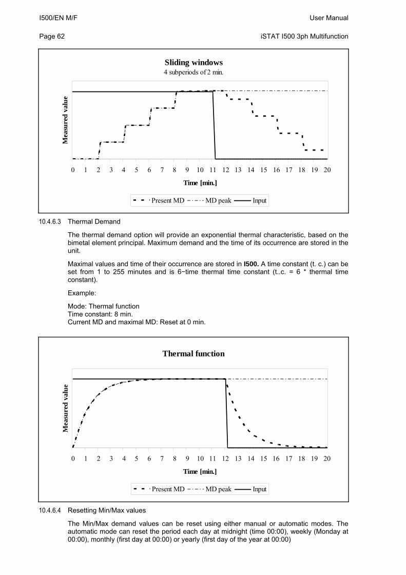
I500/EN M/F User Manual Page 62
iSTAT I500 3ph Multifunction
Sliding windows4 subperiods of 2 min.
0 1 2 3 4 5 6 7 8 9 10 11 12 13 14 15 16 17 18 19 20
Time [min.]
Mea
sure
d v
alu
e
Present MD MD peak Input
10.4.6.3 Thermal Demand
The thermal demand option will provide an exponential thermal characteristic, based on the bimetal element principal. Maximum demand and the time of its occurrence are stored in the unit.
Maximal values and time of their occurrence are stored in I500. A time constant (t. c.) can be set from 1 to 255 minutes and is 6−time thermal time constant (t..c. = 6 * thermal time constant).
Example:
Mode: Thermal function Time constant: 8 min. Current MD and maximal MD: Reset at 0 min.
Thermal function
0 1 2 3 4 5 6 7 8 9 10 11 12 13 14 15 16 17 18 19 20
Time [min.]
Mea
sure
d v
alu
e
Present MD MD peak Input
10.4.6.4 Resetting Min/Max values
The Min/Max demand values can be reset using either manual or automatic modes. The automatic mode can reset the period each day at midnight (time 00:00), weekly (Monday at 00:00), monthly (first day at 00:00) or yearly (first day of the year at 00:00)
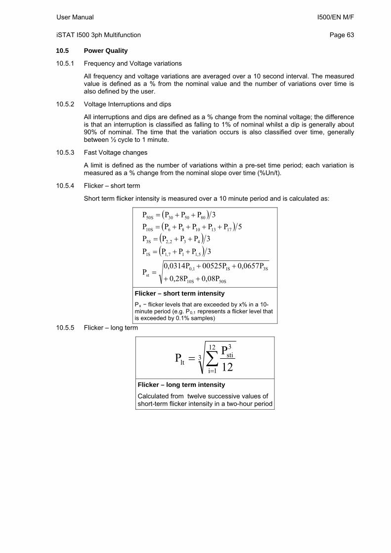
User Manual I500/EN M/F iSTAT I500 3ph Multifunction
Page 63
10.5 Power Quality
10.5.1 Frequency and Voltage variations
All frequency and voltage variations are averaged over a 10 second interval. The measured value is defined as a % from the nominal value and the number of variations over time is also defined by the user.
10.5.2 Voltage Interruptions and dips
All interruptions and dips are defined as a % change from the nominal voltage; the difference is that an interruption is classified as falling to 1% of nominal whilst a dip is generally about 90% of nominal. The time that the variation occurs is also classified over time, generally between ½ cycle to 1 minute.
10.5.3 Fast Voltage changes
A limit is defined as the number of variations within a pre-set time period; each variation is measured as a % change from the nominal slope over time (%Un/t).
10.5.4 Flicker – short term
Short term flicker intensity is measured over a 10 minute period and is calculated as:
S50S10
S3S11,0st
5,117,1S1
432,2S3
17131086S10
805030S50
P08,0P28,0
P0657,0P00525P0314,0P
3PPPP
3PPPP
5PPPPPP
3PPPP
Flicker – short term intensity
Px − flicker levels that are exceeded by x% in a 10-minute period (e.g. P0,1 represents a flicker level that is exceeded by 0.1% samples)
10.5.5 Flicker – long term
3
12
1i
3sti
lt 12
PP
Flicker – long term intensity
Calculated from twelve successive values of short-term flicker intensity in a two-hour period
I500/EN M/F User Manual Page 64
iSTAT I500 3ph Multifunction
11. COMMUNICATIONS
11.1 Communications ports
The i5MT/MR/MQ are fitted with a primary communications (COM1) port and an optional secondary port (COM2).
COM1 can be RS232/RS485, USB, or Ethernet and USB
COM2 can be RS485
Both communications ports can be used for settings and the monitoring of data, they operate completely independently of each other.
The communication parameters of the i500 can be obtained by using the ‘Scan the network’ feature in the QDSP setting software.
11.2 QDSP Setting and Monitoring Software
See the separate QDSP Manual for details of how to Install and use the QDSP Software.
11.3 MODBUS
For details, see the separate M2x3 & I500 Communications Manual.
11.4 DNP3
The implementation of DNP3 in the i5MT/MR/MQ is basic and some DNP3 Masters may have difficulty interfacing to the i5MT/MR/MQ.
For details, see the separate M2x3 & I500 Communications Manual.
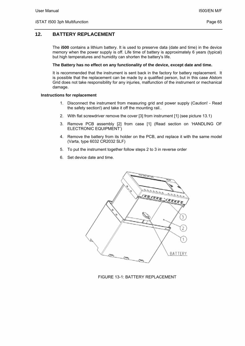
User Manual I500/EN M/F iSTAT I500 3ph Multifunction
Page 65
12. BATTERY REPLACEMENT
The i500 contains a lithium battery. It is used to preserve data (date and time) in the device memory when the power supply is off. Life time of battery is approximately 6 years (typical) but high temperatures and humidity can shorten the battery's life.
The Battery has no effect on any functionality of the device, except date and time.
It is recommended that the instrument is sent back in the factory for battery replacement. It is possible that the replacement can be made by a qualified person, but in this case Alstom Grid does not take responsibility for any injuries, malfunction of the instrument or mechanical damage.
Instructions for replacement
1. Disconnect the instrument from measuring grid and power supply (Caution! - Read the safety section!) and take it off the mounting rail..
2. With flat screwdriver remove the cover [3] from instrument [1] (see picture 13.1)
3. Remove PCB assembly [2] from case [1] (Read section on ‘HANDLING OF ELECTRONIC EQUIPMENT’)
4. Remove the battery from its holder on the PCB, and replace it with the same model (Varta, type 6032 CR2032 SLF)
5. To put the instrument together follow steps 2 to 3 in reverse order
6. Set device date and time.
FIGURE 13-1: BATTERY REPLACEMENT
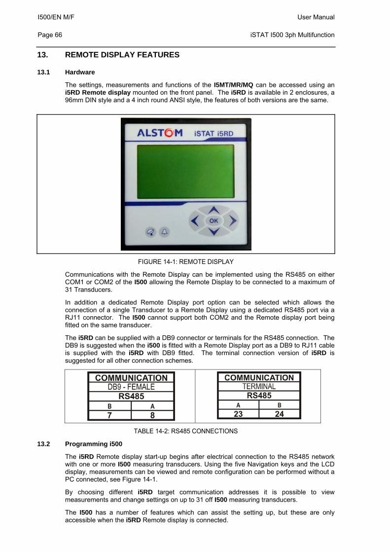
I500/EN M/F User Manual Page 66
iSTAT I500 3ph Multifunction
13. REMOTE DISPLAY FEATURES
13.1 Hardware
The settings, measurements and functions of the I5MT/MR/MQ can be accessed using an i5RD Remote display mounted on the front panel. The i5RD is available in 2 enclosures, a 96mm DIN style and a 4 inch round ANSI style, the features of both versions are the same.
FIGURE 14-1: REMOTE DISPLAY
Communications with the Remote Display can be implemented using the RS485 on either COM1 or COM2 of the I500 allowing the Remote Display to be connected to a maximum of 31 Transducers.
In addition a dedicated Remote Display port option can be selected which allows the connection of a single Transducer to a Remote Display using a dedicated RS485 port via a RJ11 connector. The I500 cannot support both COM2 and the Remote display port being fitted on the same transducer.
The i5RD can be supplied with a DB9 connector or terminals for the RS485 connection. The DB9 is suggested when the i500 is fitted with a Remote Display port as a DB9 to RJ11 cable is supplied with the i5RD with DB9 fitted. The terminal connection version of i5RD is suggested for all other connection schemes.
TABLE 14-2: RS485 CONNECTIONS
13.2 Programming i500
The i5RD Remote display start-up begins after electrical connection to the RS485 network with one or more I500 measuring transducers. Using the five Navigation keys and the LCD display, measurements can be viewed and remote configuration can be performed without a PC connected, see Figure 14-1.
By choosing different i5RD target communication addresses it is possible to view measurements and change settings on up to 31 off I500 measuring transducers.
The I500 has a number of features which can assist the setting up, but these are only accessible when the i5RD Remote display is connected.
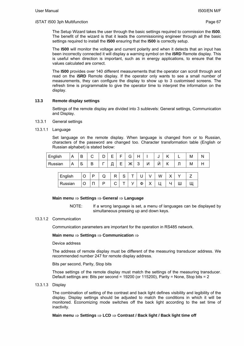
User Manual I500/EN M/F iSTAT I500 3ph Multifunction
Page 67
The Setup Wizard takes the user through the basic settings required to commission the I500. The benefit of the wizard is that it leads the commissioning engineer through all the basic settings required to install the I500 ensuring that the I500 is correctly setup.
The I500 will monitor the voltage and current polarity and when it detects that an input has been incorrectly connected it will display a warning symbol on the i5RD Remote display. This is useful when direction is important, such as in energy applications, to ensure that the values calculated are correct.
The I500 provides over 140 different measurements that the operator can scroll through and read on the i5RD Remote display. If the operator only wants to see a small number of measurements, they can configure the display to show up to 3 customised screens. The refresh time is programmable to give the operator time to interpret the information on the display.
13.3 Remote display settings
Settings of the remote display are divided into 3 sublevels: General settings, Communication and Display.
13.3.1 General settings
13.3.1.1 Language
Set language on the remote display. When language is changed from or to Russian, characters of the password are changed too. Character transformation table (English or Russian alphabet) is stated below:
English A B C D E F G H I J K L M N
Russian А Б В Г Д Е Ж З И Й К Л М Н
English O P Q R S T U V W X Y Z
Russian O П P С Т У Ф Х Ц Ч Ш Щ
Main menu Settings General Language
NOTE: If a wrong language is set, a menu of languages can be displayed by simultaneous pressing up and down keys.
13.3.1.2 Communication
Communication parameters are important for the operation in RS485 network.
Main menu Settings Communication
Device address
The address of remote display must be different of the measuring transducer address. We recommended number 247 for remote display address.
Bits per second, Parity, Stop bits
Those settings of the remote display must match the settings of the measuring transducer. Default settings are: Bits per second = 19200 (or 115200), Parity = None, Stop bits = 2
13.3.1.3 Display
The combination of setting of the contrast and back light defines visibility and legibility of the display. Display settings should be adjusted to match the conditions in which it will be monitored. Economizing mode switches off the back light according to the set time of inactivity.
Main menu Settings LCD Contrast / Back light / Back light time off
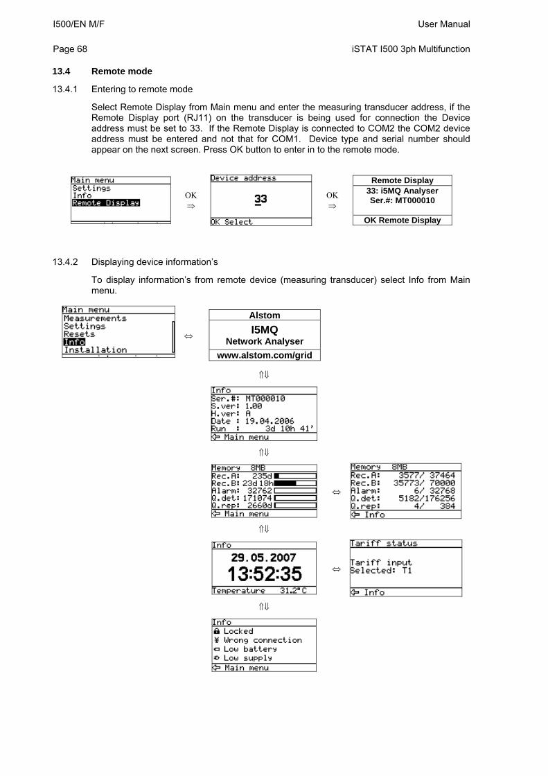
I500/EN M/F User Manual Page 68
iSTAT I500 3ph Multifunction
13.4 Remote mode
13.4.1 Entering to remote mode
Select Remote Display from Main menu and enter the measuring transducer address, if the Remote Display port (RJ11) on the transducer is being used for connection the Device address must be set to 33. If the Remote Display is connected to COM2 the COM2 device address must be entered and not that for COM1. Device type and serial number should appear on the next screen. Press OK button to enter in to the remote mode.
OK
OK
Remote Display 33: i5MQ Analyser Ser.#: MT000010
OK Remote Display
13.4.2 Displaying device information’s
To display information’s from remote device (measuring transducer) select Info from Main menu.
Alstom
I5MQ Network Analyser
www.alsto .com/grid m
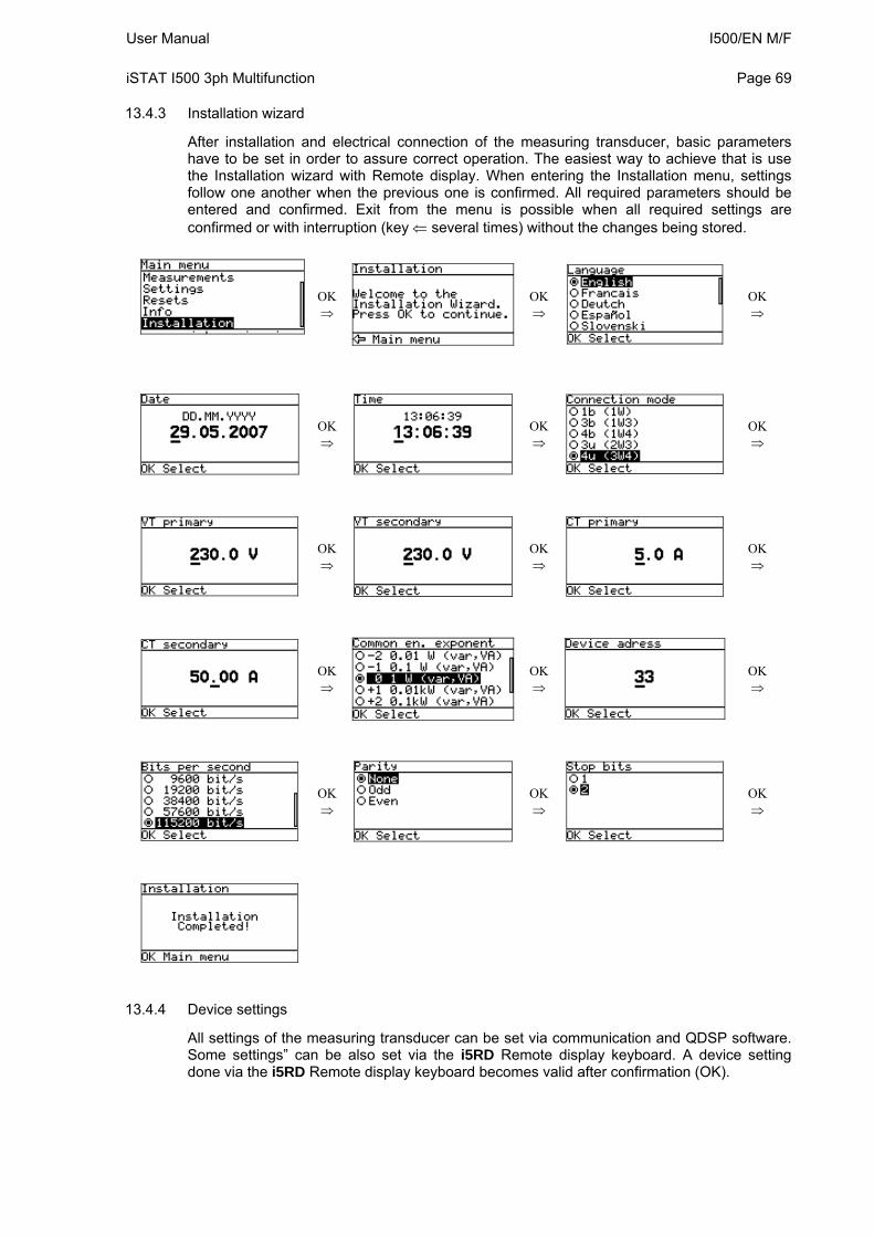
User Manual I500/EN M/F iSTAT I500 3ph Multifunction
Page 69
13.4.3 Installation wizard
After installation and electrical connection of the measuring transducer, basic parameters have to be set in order to assure correct operation. The easiest way to achieve that is use the Installation wizard with Remote display. When entering the Installation menu, settings follow one another when the previous one is confirmed. All required parameters should be entered and confirmed. Exit from the menu is possible when all required settings are confirmed or with interruption (key several times) without the changes being stored.
OK
OK
OK
OK
OK
OK
OK
OK
OK
OK
OK
OK
OK
OK
OK
13.4.4 Device settings
All settings of the measuring transducer can be set via communication and QDSP software. Some settings” can be also set via the i5RD Remote display keyboard. A device setting done via the i5RD Remote display keyboard becomes valid after confirmation (OK).
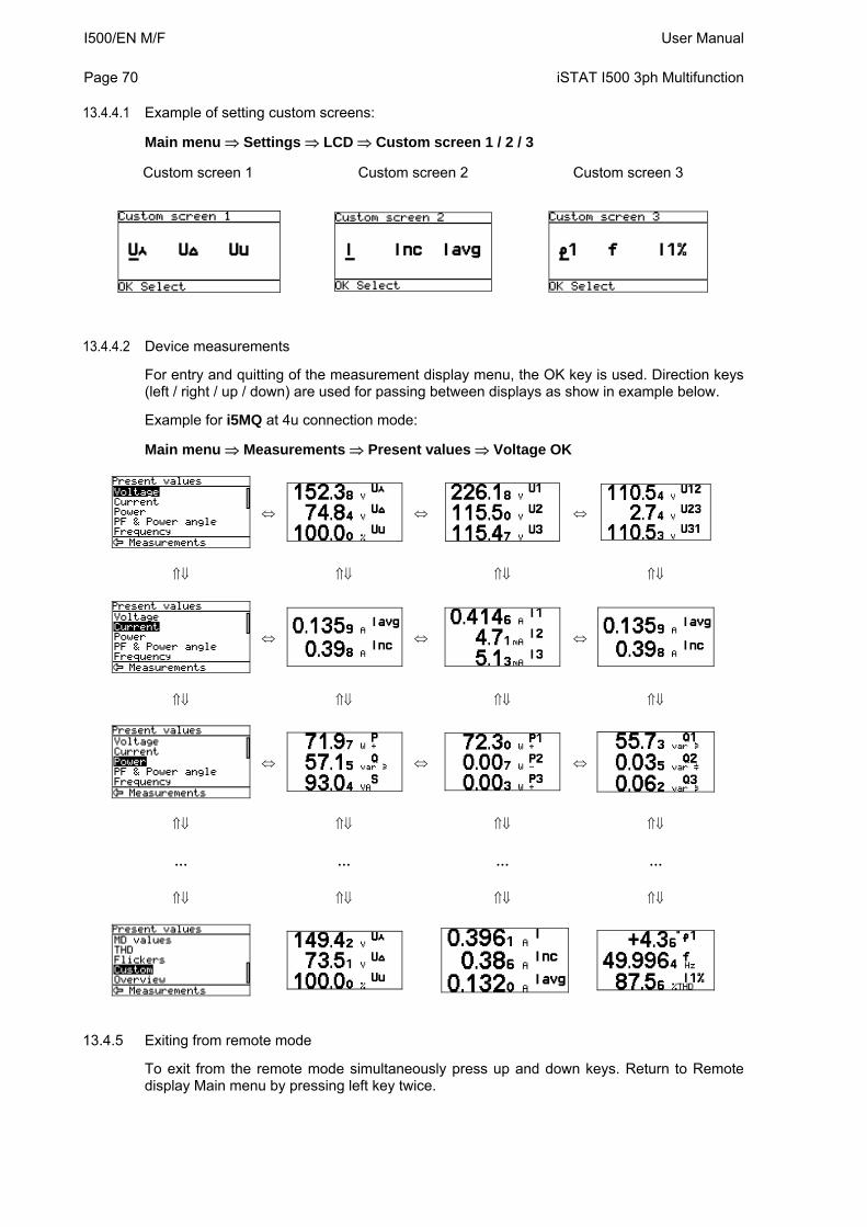
I500/EN M/F User Manual Page 70
iSTAT I500 3ph Multifunction
13.4.4.1 Example of setting custom screens:
Main menu Settings LCD Custom screen 1 / 2 / 3
Custom screen 1 Custom screen 2 Custom screen 3
13.4.4.2 Device measurements
For entry and quitting of the measurement display menu, the OK key is used. Direction keys (left / right / up / down) are used for passing between displays as show in example below.
Example for i5MQ at 4u connection mode:
Main menu Measurements Present values Voltage OK
… … … …
13.4.5 Exiting from remote mode
To exit from the remote mode simultaneously press up and down keys. Return to Remote display Main menu by pressing left key twice.
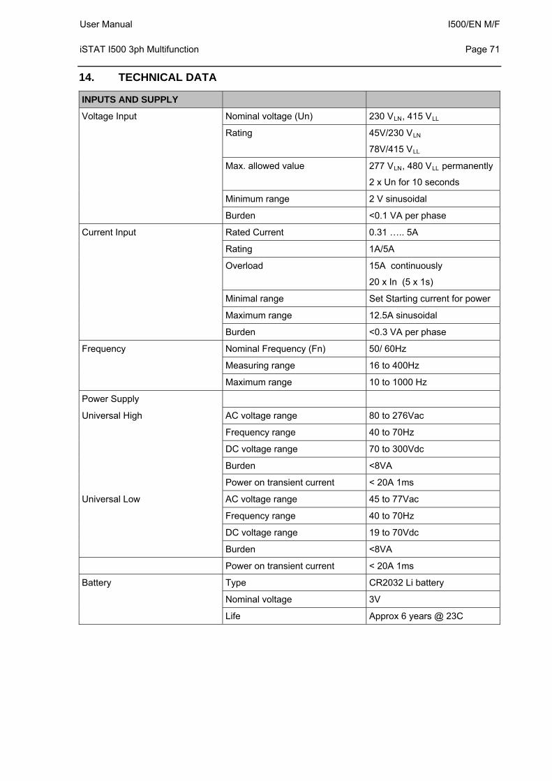
User Manual I500/EN M/F iSTAT I500 3ph Multifunction
Page 71
14. TECHNICAL DATA
INPUTS AND SUPPLY
Voltage Input Nominal voltage (Un) 230 VLN, 415 VLL
Rating 45V/230 VLN
78V/415 VLL
Max. allowed value 277 VLN, 480 VLL permanently
2 x Un for 10 seconds
Minimum range 2 V sinusoidal
Burden <0.1 VA per phase
Current Input Rated Current 0.31 ….. 5A
Rating 1A/5A
Overload 15A continuously
20 x In (5 x 1s)
Minimal range Set Starting current for power
Maximum range 12.5A sinusoidal
Burden <0.3 VA per phase
Frequency Nominal Frequency (Fn) 50/ 60Hz
Measuring range 16 to 400Hz
Maximum range 10 to 1000 Hz
Power Supply
Universal High AC voltage range 80 to 276Vac
Frequency range 40 to 70Hz
DC voltage range 70 to 300Vdc
Burden <8VA
Power on transient current < 20A 1ms
Universal Low AC voltage range 45 to 77Vac
Frequency range 40 to 70Hz
DC voltage range 19 to 70Vdc
Burden <8VA
Power on transient current < 20A 1ms
Battery Type CR2032 Li battery
Nominal voltage 3V
Life Approx 6 years @ 23C
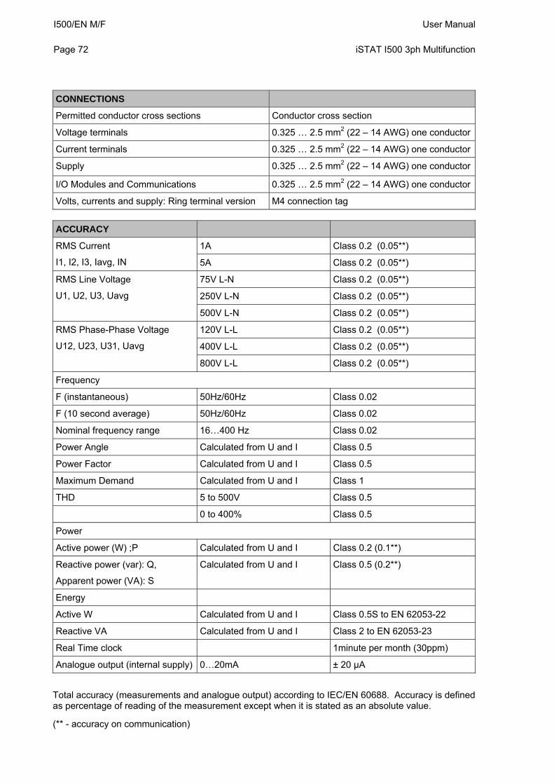
I500/EN M/F User Manual Page 72
iSTAT I500 3ph Multifunction
CONNECTIONS
Permitted conductor cross sections Conductor cross section
Voltage terminals 0.325 … 2.5 mm2 (22 – 14 AWG) one conductor
Current terminals 0.325 … 2.5 mm2 (22 – 14 AWG) one conductor
Supply 0.325 … 2.5 mm2 (22 – 14 AWG) one conductor
I/O Modules and Communications 0.325 … 2.5 mm2 (22 – 14 AWG) one conductor
Volts, currents and supply: Ring terminal version M4 connection tag
ACCURACY
1A Class 0.2 (0.05**) RMS Current
I1, I2, I3, Iavg, IN 5A Class 0.2 (0.05**)
75V L-N Class 0.2 (0.05**)
250V L-N Class 0.2 (0.05**)
RMS Line Voltage
U1, U2, U3, Uavg
500V L-N Class 0.2 (0.05**)
120V L-L Class 0.2 (0.05**)
400V L-L Class 0.2 (0.05**)
RMS Phase-Phase Voltage
U12, U23, U31, Uavg
800V L-L Class 0.2 (0.05**)
Frequency
F (instantaneous) 50Hz/60Hz Class 0.02
F (10 second average) 50Hz/60Hz Class 0.02
Nominal frequency range 16…400 Hz Class 0.02
Power Angle Calculated from U and I Class 0.5
Power Factor Calculated from U and I Class 0.5
Maximum Demand Calculated from U and I Class 1
THD 5 to 500V Class 0.5
0 to 400% Class 0.5
Power
Active power (W) ;P Calculated from U and I Class 0.2 (0.1**)
Reactive power (var): Q,
Apparent power (VA): S
Calculated from U and I Class 0.5 (0.2**)
Energy
Active W Calculated from U and I Class 0.5S to EN 62053-22
Reactive VA Calculated from U and I Class 2 to EN 62053-23
Real Time clock 1minute per month (30ppm)
Analogue output (internal supply) 0…20mA ± 20 µA
Total accuracy (measurements and analogue output) according to IEC/EN 60688. Accuracy is defined as percentage of reading of the measurement except when it is stated as an absolute value.
(** - accuracy on communication)
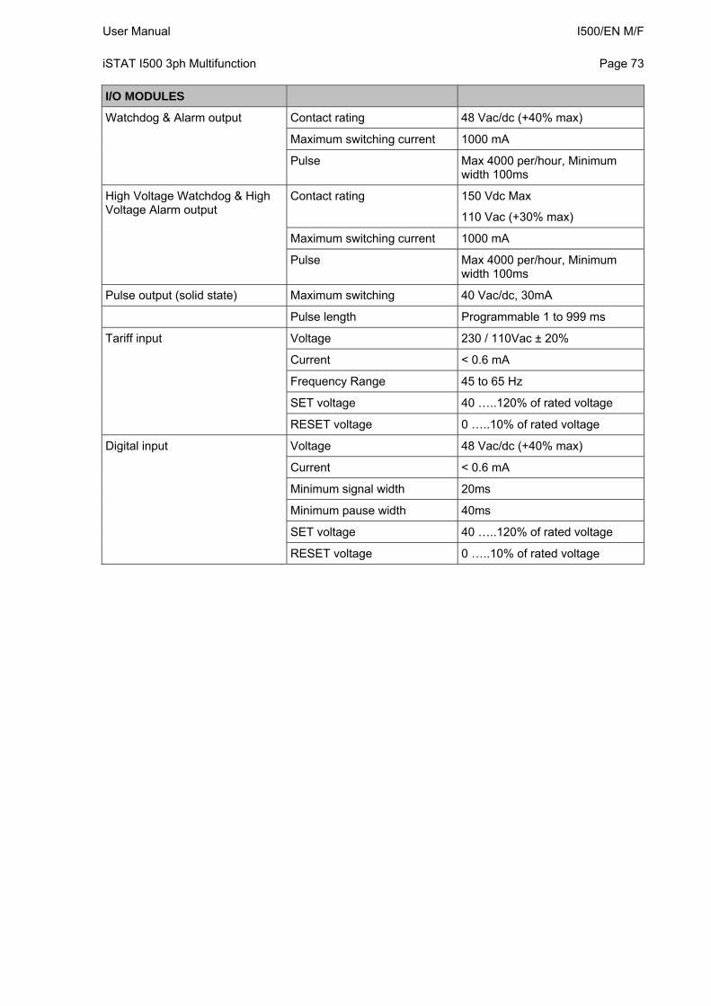
User Manual I500/EN M/F iSTAT I500 3ph Multifunction
Page 73
I/O MODULES
Watchdog & Alarm output Contact rating 48 Vac/dc (+40% max)
Maximum switching current 1000 mA
Pulse Max 4000 per/hour, Minimum width 100ms
High Voltage Watchdog & High Voltage Alarm output
Contact rating 150 Vdc Max
110 Vac (+30% max)
Maximum switching current 1000 mA
Pulse Max 4000 per/hour, Minimum width 100ms
Pulse output (solid state) Maximum switching 40 Vac/dc, 30mA
Pulse length Programmable 1 to 999 ms
Tariff input Voltage 230 / 110Vac ± 20%
Current < 0.6 mA
Frequency Range 45 to 65 Hz
SET voltage 40 …..120% of rated voltage
RESET voltage 0 …..10% of rated voltage
Digital input Voltage 48 Vac/dc (+40% max)
Current < 0.6 mA
Minimum signal width 20ms
Minimum pause width 40ms
SET voltage 40 …..120% of rated voltage
RESET voltage 0 …..10% of rated voltage
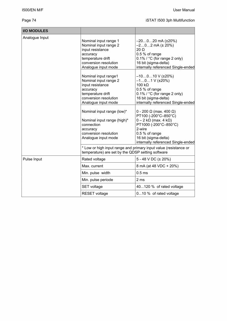
I500/EN M/F User Manual Page 74
iSTAT I500 3ph Multifunction
I/O MODULES
Analogue Input Nominal input range 1 Nominal input range 2 input resistance accuracy temperature drift conversion resolution Analogue input mode
–20…0…20 mA (±20%) –2…0…2 mA (± 20%) 20 Ω 0.5 % of range 0.1% / °C (for range 2 only) 16 bit (sigma-delta) internally referenced Single-ended
Nominal input range1 Nominal input range 2 input resistance accuracy temperature drift conversion resolution Analogue input mode
–10…0…10 V (±20%) –1…0…1 V (±20%) 100 kΩ 0.5 % of range 0.1% / °C (for range 2 only) 16 bit (sigma-delta) internally referenced Single-ended
Nominal input range (low)* Nominal input range (high)* connection accuracy conversion resolution Analogue input mode
0 - 200 Ω (max. 400 Ω) PT100 (-200°C–850°C) 0 – 2 kΩ (max. 4 kΩ) PT1000 (-200°C–850°C) 2-wire 0.5 % of range 16 bit (sigma-delta) internally referenced Single-ended
* Low or high input range and primary input value (resistance or temperature) are set by the QDSP setting software
Pulse Input Rated voltage 5 - 48 V DC (± 20%)
Max. current 8 mA (at 48 VDC + 20%)
Min. pulse width 0.5 ms
Min. pulse periode 2 ms
SET voltage 40...120 % of rated voltage
RESET voltage 0...10 % of rated voltage
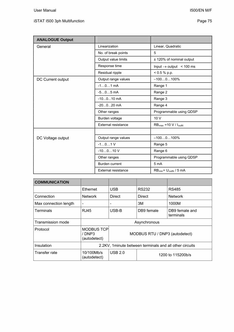
User Manual I500/EN M/F iSTAT I500 3ph Multifunction
Page 75
ANALOGUE Output
General Linearization Linear, Quadratic
No. of break points 5
Output value limits ± 120% of nominal output
Response time Input output < 100 ms
Residual ripple < 0.5 % p.p.
DC Current output Output range values –100…0…100%
-1…0…1 mA Range 1
-5…0…5 mA Range 2
-10...0...10 mA Range 3
-20...0...20 mA Range 4
Other ranges Programmable using QDSP
Burden voltage 10 V
External resistance RBmax =10 V / IoutN
DC Voltage output Output range values –100…0…100%
-1…0…1 V Range 5
-10…0…10 V Range 6
Other ranges Programmable using QDSP
Burden current 5 mA
External resistance RBmin= UoutN / 5 mA
COMMUNICATION
Ethernet USB RS232 RS485
Connection Network Direct Direct Network
Max connection length - - 3M 1000M
Terminals RJ45 USB-B DB9 female DB9 female and terminals
Transmission mode Asynchronous
Protocol MODBUS TCP / DNP3 (autodetect)
MODBUS RTU / DNP3 (autodetect)
Insulation 2.2KV, 1minute between terminals and all other circuits
Transfer rate 10/100Mb/s (autodetect)
USB 2.0 1200 to 115200b/s
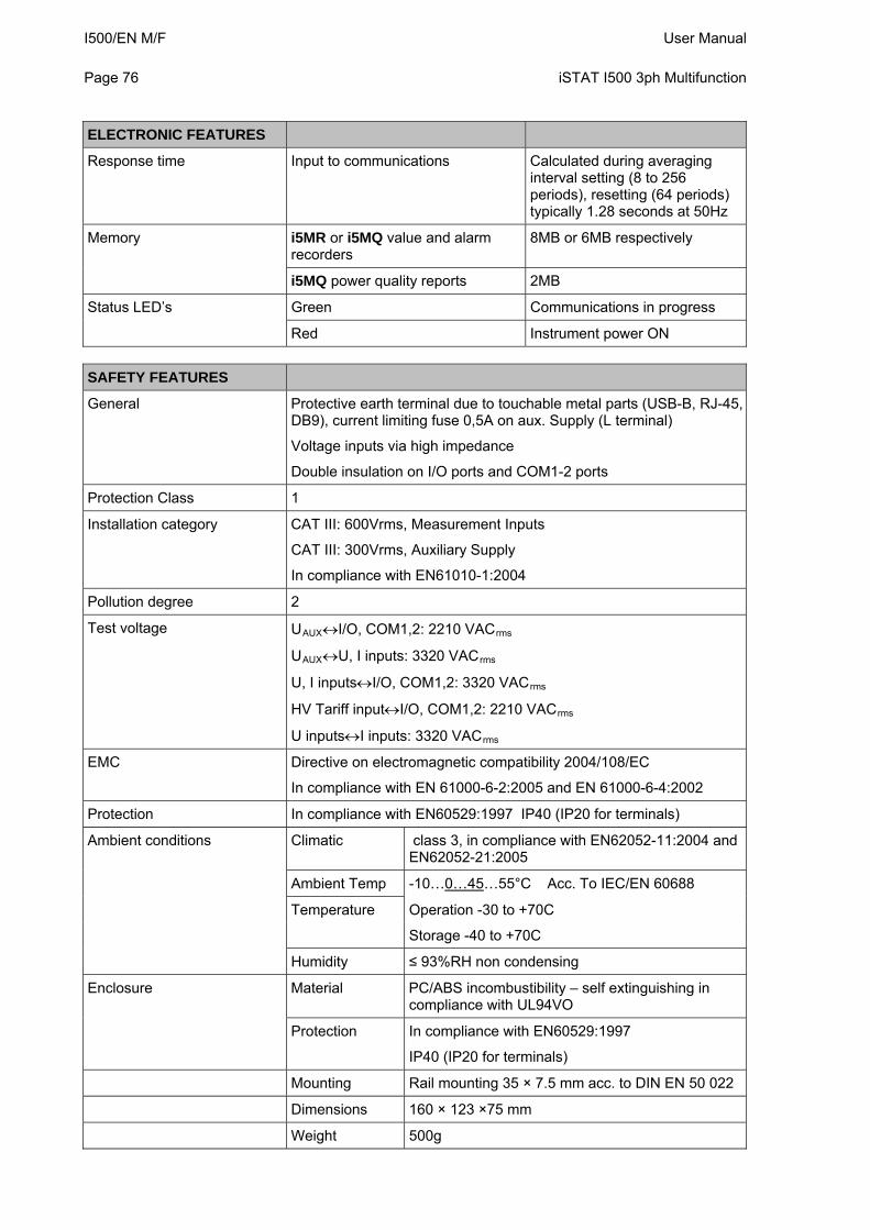
I500/EN M/F User Manual Page 76
iSTAT I500 3ph Multifunction
ELECTRONIC FEATURES
Response time Input to communications Calculated during averaging interval setting (8 to 256 periods), resetting (64 periods) typically 1.28 seconds at 50Hz
Memory i5MR or i5MQ value and alarm recorders
8MB or 6MB respectively
i5MQ power quality reports 2MB
Status LED’s Green Communications in progress
Red Instrument power ON
SAFETY FEATURES
General Protective earth terminal due to touchable metal parts (USB-B, RJ-45, DB9), current limiting fuse 0,5A on aux. Supply (L terminal)
Voltage inputs via high impedance
Double insulation on I/O ports and COM1-2 ports
Protection Class 1
Installation category CAT III: 600Vrms, Measurement Inputs
CAT III: 300Vrms, Auxiliary Supply
In compliance with EN61010-1:2004
Pollution degree 2
Test voltage UAUXI/O, COM1,2: 2210 VACrms
UAUXU, I inputs: 3320 VACrms
U, I inputsI/O, COM1,2: 3320 VACrms
HV Tariff inputI/O, COM1,2: 2210 VACrms
U inputsI inputs: 3320 VACrms
EMC Directive on electromagnetic compatibility 2004/108/EC
In compliance with EN 61000-6-2:2005 and EN 61000-6-4:2002
Protection In compliance with EN60529:1997 IP40 (IP20 for terminals)
Ambient conditions Climatic class 3, in compliance with EN62052-11:2004 and EN62052-21:2005
Ambient Temp -10…0…45…55°C Acc. To IEC/EN 60688
Temperature Operation -30 to +70C
Storage -40 to +70C
Humidity ≤ 93%RH non condensing
Enclosure Material PC/ABS incombustibility – self extinguishing in compliance with UL94VO
Protection In compliance with EN60529:1997
IP40 (IP20 for terminals)
Mounting Rail mounting 35 × 7.5 mm acc. to DIN EN 50 022
Dimensions 160 × 123 ×75 mm
Weight 500g
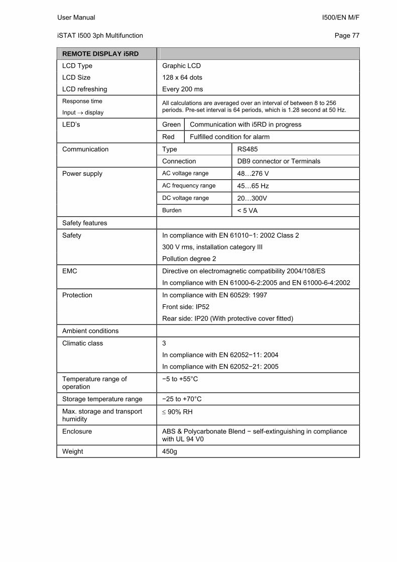
User Manual I500/EN M/F iSTAT I500 3ph Multifunction
Page 77
REMOTE DISPLAY i5RD
LCD Type Graphic LCD
LCD Size 128 x 64 dots
LCD refreshing Every 200 ms
Response time
Input display
All calculations are averaged over an interval of between 8 to 256 periods. Pre-set interval is 64 periods, which is 1.28 second at 50 Hz.
LED’s Green Communication with i5RD in progress
Red Fulfilled condition for alarm
Communication Type RS485
Connection DB9 connector or Terminals
Power supply AC voltage range 48…276 V
AC frequency range 45…65 Hz
DC voltage range 20…300V
Burden < 5 VA
Safety features
Safety In compliance with EN 61010−1: 2002 Class 2
300 V rms, installation category III
Pollution degree 2
EMC Directive on electromagnetic compatibility 2004/108/ES
In compliance with EN 61000-6-2:2005 and EN 61000-6-4:2002
Protection In compliance with EN 60529: 1997
Front side: IP52
Rear side: IP20 (With protective cover fitted)
Ambient conditions
Climatic class 3
In compliance with EN 62052−11: 2004
In compliance with EN 62052−21: 2005
Temperature range of operation
−5 to +55°C
Storage temperature range −25 to +70°C
Max. storage and transport humidity
90% RH
Enclosure ABS & Polycarbonate Blend − self-extinguishing in compliance with UL 94 V0
Weight 450g
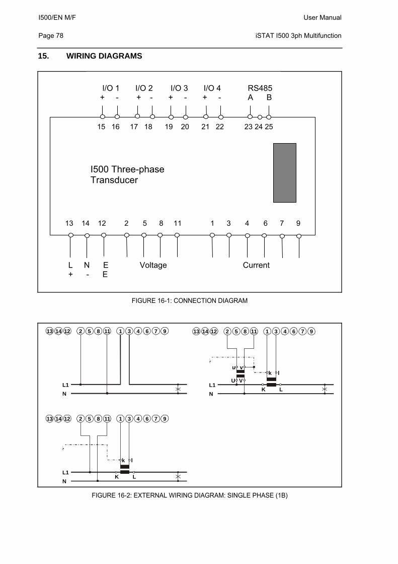
I500/EN M/F User Manual Page 78
iSTAT I500 3ph Multifunction
15. WIRING DIAGRAMS
FIGURE 16-1: CONNECTION DIAGRAM
U
u
V
v
N
N
N
L1
L1
L1
K
K
L
L
k
k
l
l
2
2
25
5
58
8
811
11
111
1
13
3
34
4
47
7
76
6
69
9
914
14
1413
13
1312
12
12
FIGURE 16-2: EXTERNAL WIRING DIAGRAM: SINGLE PHASE (1B)
15 16 17 18 19 20 21 22 23 24 25
I500 Three-phase Transducer
13 14 12 2 5 8 11 1 3 4 6 7 9
I/O 1 I/O 2 I/O 3 I/O 4 RS485 + - + - + - + - A B
L N E Voltage Current + - E
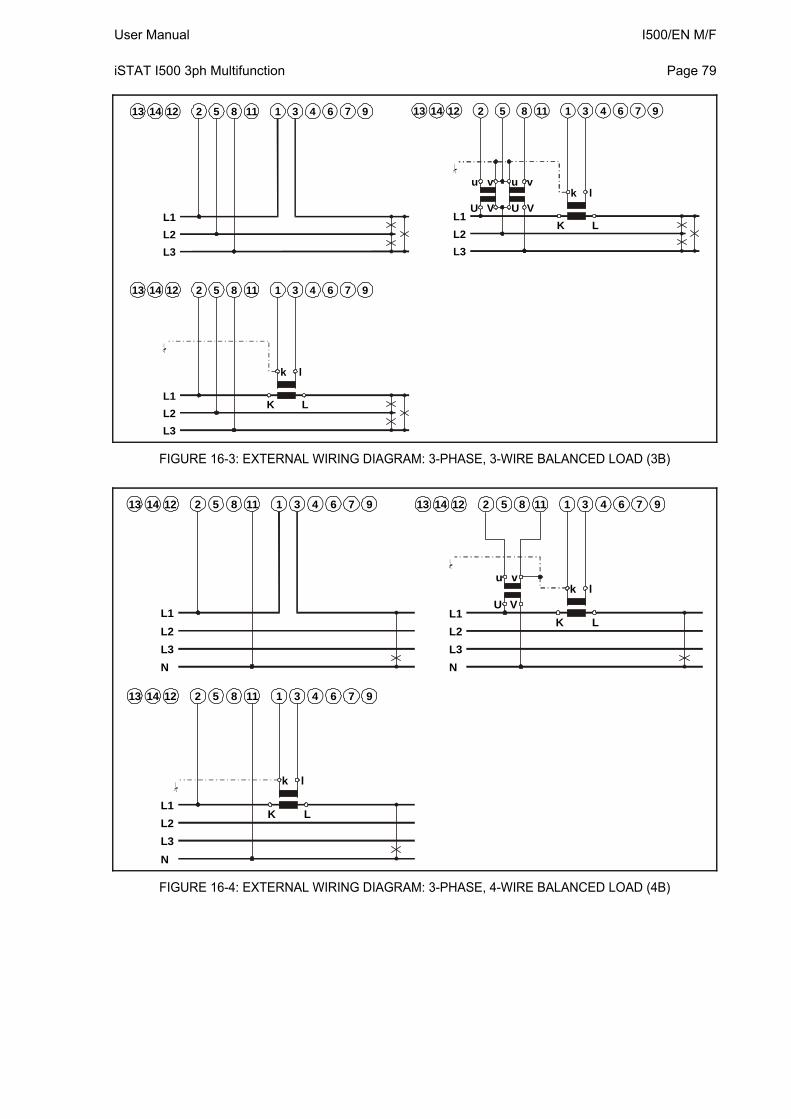
User Manual I500/EN M/F iSTAT I500 3ph Multifunction
Page 79
U
u
V
v
L3
L3
L3
L2
L2
L2
L1
L1
L1U
u
V
v
K
K
L
L
k
k
l
l
2
2
25
5
58
8
811
11
111
1
13
3
34
4
47
7
76
6
69
9
914
14
1413
13
1312
12
12
FIGURE 16-3: EXTERNAL WIRING DIAGRAM: 3-PHASE, 3-WIRE BALANCED LOAD (3B)
U
u
V
v
N
N
N
L1
L2
L2
L2
L3
L3
L3
L1
L1
K
K
L
L
k
k
l
l
2
2
25
5
58
8
811
11
111
1
13
3
34
4
47
7
76
6
69
9
914
14
1413
13
1312
12
12
FIGURE 16-4: EXTERNAL WIRING DIAGRAM: 3-PHASE, 4-WIRE BALANCED LOAD (4B)
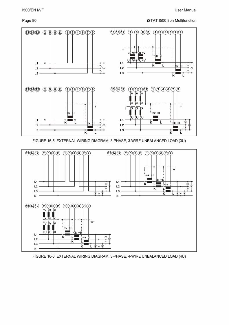
I500/EN M/F User Manual Page 80
iSTAT I500 3ph Multifunction
X X
x x
X
x
U
U
u
U
V
v
u u
L3
L3
L3
L3
L2
L2
L2
L2
L1
L1
L1
L1U
U
u
V
v
u
l
l
lk
k
k
L
L
LK
K
K
K
K
KL
L
L
k
k
kl
l
l
2
2
2
2
5
5
5
5
8
8
8
8
11
11
11
11
1
1
1
1
3
3
3
3
4
4
4
4
7
7
7
7
6
6
6
6
9
9
9
9
14
14
14
14
13
13
13
13
12
12
12
12
FIGURE 16-5: EXTERNAL WIRING DIAGRAM: 3-PHASE, 3-WIRE UNBALANCED LOAD (3U)
FIGURE 16-6: EXTERNAL WIRING DIAGRAM: 3-PHASE, 4-WIRE UNBALANCED LOAD (4U)
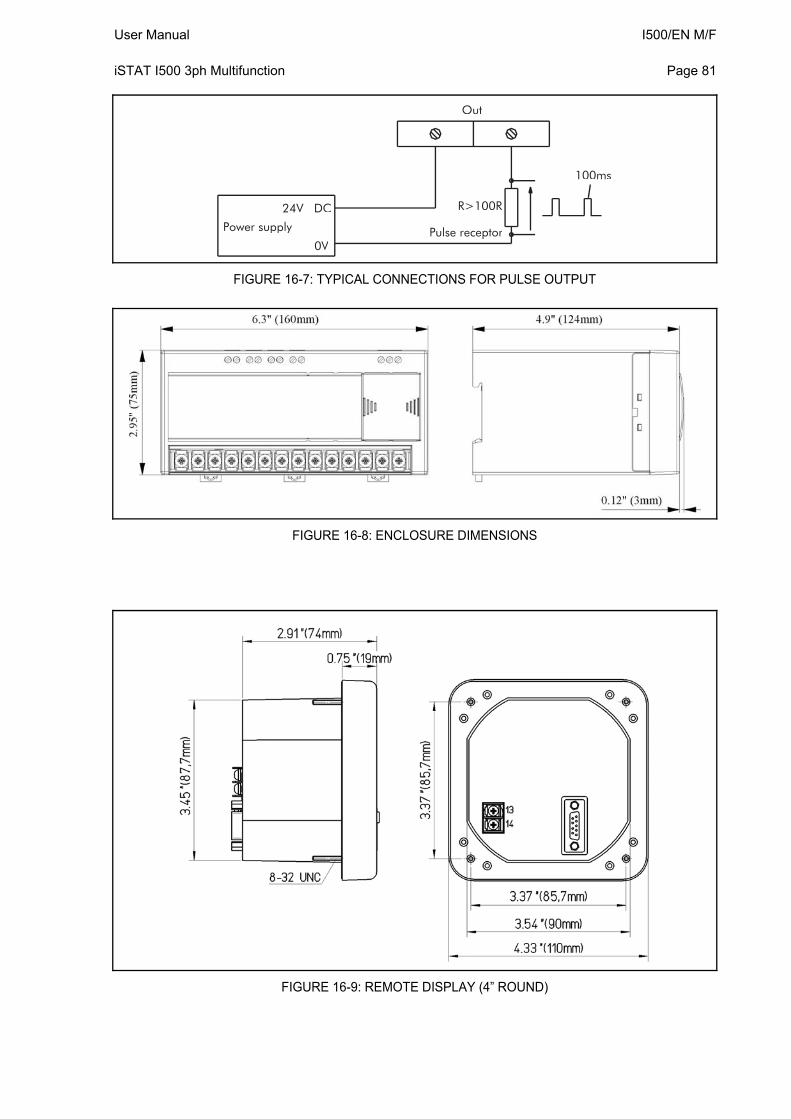
User Manual I500/EN M/F iSTAT I500 3ph Multifunction
Page 81
100ms
Out
R>100R
Pulse receptor
24V DC
0V
Power supply
FIGURE 16-7: TYPICAL CONNECTIONS FOR PULSE OUTPUT
FIGURE 16-8: ENCLOSURE DIMENSIONS
FIGURE 16-9: REMOTE DISPLAY (4” ROUND)
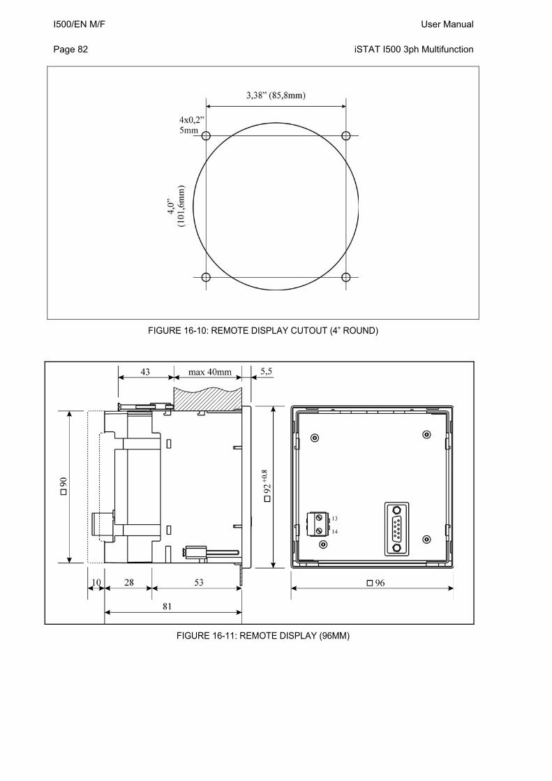
I500/EN M/F User Manual Page 82
iSTAT I500 3ph Multifunction
FIGURE 16-10: REMOTE DISPLAY CUTOUT (4” ROUND)
FIGURE 16-11: REMOTE DISPLAY (96MM)
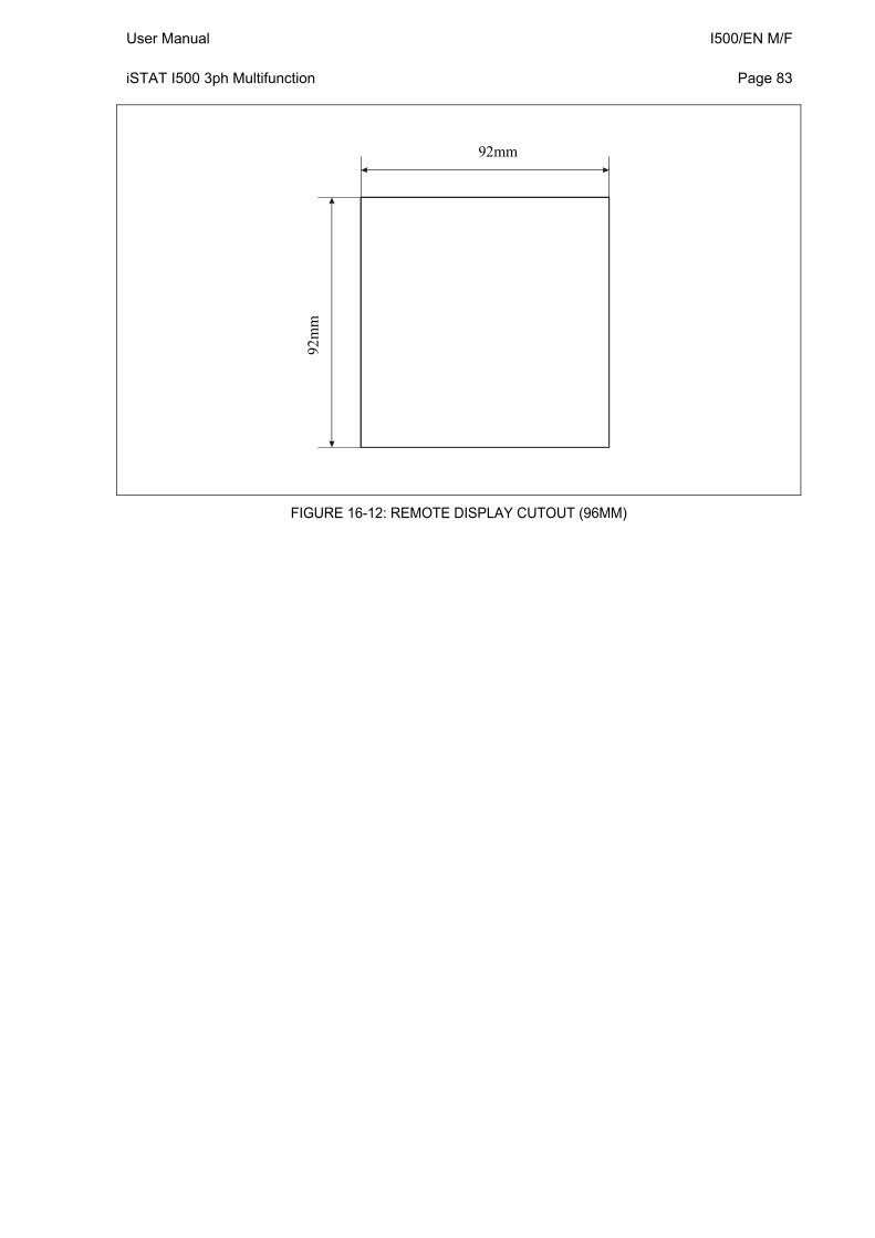
User Manual I500/EN M/F iSTAT I500 3ph Multifunction
Page 83
92mm
92m
m
FIGURE 16-12: REMOTE DISPLAY CUTOUT (96MM)

I500/EN M/F User Manual Page 84
iSTAT I500 3ph Multifunction
16. RELATED DOCUMENTS
Ref Document
1 I500 Single Phase Transducer Manual
2 I500 and M2x3 Communications Manual
3 QDSP Technical Manual


PXXX Product Description
Alstom Grid
© - ALSTOM 2014. ALSTOM, the ALSTOM logo and any alternative version thereof are trademarks and service marks of ALSTOM. The other names mentioned, registered or not, are the property of their respective companies. The technical and other data contained in this document is provided for information only. Neither ALSTOM, its officers or employees accept responsibility for, or should be taken as making any representation or warranty (whether express or implied), as to the accuracy or completeness of such data or the achievement of any projected performance criteria where these are indicated. ALSTOM reserves the right to revise or change this data at any time without further notice.
Alstom Grid Worldwide Contact Centre
www.grid.alstom.com/contactcentre/
Tel: +44 (0) 1785 250 070
www.alstom.com
GRID