Embed Size (px)
Citation preview

ibm.com/redbooks
LPAR Configuration and ManagementWorking with IBM iSeries Logical Partitions
Nick HarrisDale Barrick
Ian CaiPeter G Croes
Adriel JohndroBob Klingelhoets
Steve MannNihal Perera
Robert Taylor
Learn how to use the new V5R1 dynamic resource movements in LPAR
See how to use the new GUI interface for LPAR
Use the V5R1 LAN console and virtual LAN facilities
Front cover


International Technical Support Organization SG24-6251-00
LPAR Configuration and Management: Working with IBM ~ iSeries Logical Partitions
April 2002

© Copyright International Business Machines Corporation 2002. All rights reserved.Note to U.S Government Users - Documentation related to restricted rights - Use, duplication or disclosure is subject to restrictionsset forth in GSA ADP Schedule Contract with IBM Corp.
First Edition (April 2002)
This edition applies to OS/400 Version 5, Release 1.
Comments may be addressed to:IBM Corporation, International Technical Support OrganizationDept. JLU Building 107-23605 Highway 52NRochester, Minnesota 55901-7829
When you send information to IBM, you grant IBM a non-exclusive right to use or distribute the information in any way it believes appropriate without incurring any obligation to you.
Before using this information and the product it supports, be sure to read the general information in “Special notices” on page xi.
Take Note!

Contents
Contents . . . . . . . . . . . . . . . . . . . . . . . . . . . . . . . . . . . . . . . . . . . . . . . . . . . . . . . . . . . . . . . . iii
Special notices . . . . . . . . . . . . . . . . . . . . . . . . . . . . . . . . . . . . . . . . . . . . . . . . . . . . . . . . . . . xi
IBM trademarks . . . . . . . . . . . . . . . . . . . . . . . . . . . . . . . . . . . . . . . . . . . . . . . . . . . . . . . . . . xii
Preface . . . . . . . . . . . . . . . . . . . . . . . . . . . . . . . . . . . . . . . . . . . . . . . . . . . . . . . . . . . . . . . . xiiiThe team that wrote this redbook. . . . . . . . . . . . . . . . . . . . . . . . . . . . . . . . . . . . . . . . . . . . . xiiiNotice . . . . . . . . . . . . . . . . . . . . . . . . . . . . . . . . . . . . . . . . . . . . . . . . . . . . . . . . . . . . . . . . . . .xvComments welcome. . . . . . . . . . . . . . . . . . . . . . . . . . . . . . . . . . . . . . . . . . . . . . . . . . . . . . . .xv
Chapter 1. Logical partitioning concepts . . . . . . . . . . . . . . . . . . . . . . . . . . . . . . . . . . . . . 11.1 Logical partitioning introduction. . . . . . . . . . . . . . . . . . . . . . . . . . . . . . . . . . . . . . . . . . . . 2
1.1.1 Logical partitioning history . . . . . . . . . . . . . . . . . . . . . . . . . . . . . . . . . . . . . . . . . . . 21.1.2 LPAR at V4R4 and V4R5 . . . . . . . . . . . . . . . . . . . . . . . . . . . . . . . . . . . . . . . . . . . . 21.1.3 What’s new with V5R1 . . . . . . . . . . . . . . . . . . . . . . . . . . . . . . . . . . . . . . . . . . . . . . 3
1.2 Shared versus dedicated processors . . . . . . . . . . . . . . . . . . . . . . . . . . . . . . . . . . . . . . . 41.2.1 Dedicated processors . . . . . . . . . . . . . . . . . . . . . . . . . . . . . . . . . . . . . . . . . . . . . . . 41.2.2 Shared processors . . . . . . . . . . . . . . . . . . . . . . . . . . . . . . . . . . . . . . . . . . . . . . . . . 5
1.3 Server consolidation . . . . . . . . . . . . . . . . . . . . . . . . . . . . . . . . . . . . . . . . . . . . . . . . . . . . 61.4 Logical partitioning scenarios . . . . . . . . . . . . . . . . . . . . . . . . . . . . . . . . . . . . . . . . . . . . . 7
1.4.1 Workload consolidation . . . . . . . . . . . . . . . . . . . . . . . . . . . . . . . . . . . . . . . . . . . . . . 71.4.2 Global server consolidation. . . . . . . . . . . . . . . . . . . . . . . . . . . . . . . . . . . . . . . . . . . 81.4.3 Domino partitions and iSeries logical partitions . . . . . . . . . . . . . . . . . . . . . . . . . . . 91.4.4 Linux as a guest on iSeries. . . . . . . . . . . . . . . . . . . . . . . . . . . . . . . . . . . . . . . . . . . 91.4.5 Granular failover and backup scenarios in LPAR . . . . . . . . . . . . . . . . . . . . . . . . . 10
1.5 Upgrading an existing LPAR . . . . . . . . . . . . . . . . . . . . . . . . . . . . . . . . . . . . . . . . . . . . . 121.5.1 Thin primary . . . . . . . . . . . . . . . . . . . . . . . . . . . . . . . . . . . . . . . . . . . . . . . . . . . . . 12
1.6 LPAR and iSeries clusters . . . . . . . . . . . . . . . . . . . . . . . . . . . . . . . . . . . . . . . . . . . . . . 121.7 Independent auxiliary storage pools (IASPs) . . . . . . . . . . . . . . . . . . . . . . . . . . . . . . . . 13
Chapter 2. Understanding logical partitioning . . . . . . . . . . . . . . . . . . . . . . . . . . . . . . . . 152.1 LPAR basics . . . . . . . . . . . . . . . . . . . . . . . . . . . . . . . . . . . . . . . . . . . . . . . . . . . . . . . . . 16
2.1.1 Available hardware function, listed by model . . . . . . . . . . . . . . . . . . . . . . . . . . . . 162.1.2 Hardware and software support . . . . . . . . . . . . . . . . . . . . . . . . . . . . . . . . . . . . . . 172.1.3 Partition support by model . . . . . . . . . . . . . . . . . . . . . . . . . . . . . . . . . . . . . . . . . . 182.1.4 Minimum hardware requirements . . . . . . . . . . . . . . . . . . . . . . . . . . . . . . . . . . . . . 202.1.5 Component minimum and maximum values . . . . . . . . . . . . . . . . . . . . . . . . . . . . . 212.1.6 Processors . . . . . . . . . . . . . . . . . . . . . . . . . . . . . . . . . . . . . . . . . . . . . . . . . . . . . . 212.1.7 Examples in shared processing . . . . . . . . . . . . . . . . . . . . . . . . . . . . . . . . . . . . . . 242.1.8 Single processor shared pool with multiple partitions . . . . . . . . . . . . . . . . . . . . . . 242.1.9 Multiple processor shared pool with multiple partitions. . . . . . . . . . . . . . . . . . . . . 252.1.10 Multiple shared processors, partitions, and virtual processors . . . . . . . . . . . . . . 272.1.11 Batch workloads: More details . . . . . . . . . . . . . . . . . . . . . . . . . . . . . . . . . . . . . . 28
2.2 Logical partition arrangement . . . . . . . . . . . . . . . . . . . . . . . . . . . . . . . . . . . . . . . . . . . . 292.2.1 Hardware assignment to partitions . . . . . . . . . . . . . . . . . . . . . . . . . . . . . . . . . . . . 312.2.2 Partitioning levels: Bus ownership . . . . . . . . . . . . . . . . . . . . . . . . . . . . . . . . . . . . 332.2.3 Bus ownership . . . . . . . . . . . . . . . . . . . . . . . . . . . . . . . . . . . . . . . . . . . . . . . . . . . 332.2.4 IOP in logical partitions . . . . . . . . . . . . . . . . . . . . . . . . . . . . . . . . . . . . . . . . . . . . . 34
© Copyright IBM Corp. 2002 iii

2.2.5 Memory . . . . . . . . . . . . . . . . . . . . . . . . . . . . . . . . . . . . . . . . . . . . . . . . . . . . . . . . . 352.2.6 Interactive performance . . . . . . . . . . . . . . . . . . . . . . . . . . . . . . . . . . . . . . . . . . . . 352.2.7 Console options . . . . . . . . . . . . . . . . . . . . . . . . . . . . . . . . . . . . . . . . . . . . . . . . . . 362.2.8 Upgrade considerations . . . . . . . . . . . . . . . . . . . . . . . . . . . . . . . . . . . . . . . . . . . . 38
2.3 Software requirements . . . . . . . . . . . . . . . . . . . . . . . . . . . . . . . . . . . . . . . . . . . . . . . . . 392.3.1 OS/400 release support for the n-way Sx0, 6xx, and 7xx models . . . . . . . . . . . . 392.3.2 OS/400 release support for the n-way 8xx models . . . . . . . . . . . . . . . . . . . . . . . . 392.3.3 OS/400 release support for the new 270 and 8xx models . . . . . . . . . . . . . . . . . . 402.3.4 Available LPAR function listed by release. . . . . . . . . . . . . . . . . . . . . . . . . . . . . . . 402.3.5 Application workload analysis . . . . . . . . . . . . . . . . . . . . . . . . . . . . . . . . . . . . . . . . 41
Chapter 3. Planning for logical partitions . . . . . . . . . . . . . . . . . . . . . . . . . . . . . . . . . . . . 433.1 Planning and data collection . . . . . . . . . . . . . . . . . . . . . . . . . . . . . . . . . . . . . . . . . . . . . 44
3.1.1 Hardware and software assessment and system design . . . . . . . . . . . . . . . . . . . 453.1.2 Planning the implementation. . . . . . . . . . . . . . . . . . . . . . . . . . . . . . . . . . . . . . . . . 46
3.2 Planning examples . . . . . . . . . . . . . . . . . . . . . . . . . . . . . . . . . . . . . . . . . . . . . . . . . . . . 463.2.1 Example 1: Implement LPAR on a new/existing Model 270 . . . . . . . . . . . . . . . . . 473.2.2 Example 2: Implementing LPAR on a 720 with MES upgrade to an 830 . . . . . . . 483.2.3 Example 3: Implementing LPAR on 730 to 830 MES upgrade with a thin primary 503.2.4 Example 4: Implementing LPAR on an existing 830 with a thin primary. . . . . . . . 523.2.5 Example 5: Implementing a shell LPAR as part of an LPAR configuration. . . . . . 54
3.3 Complexity . . . . . . . . . . . . . . . . . . . . . . . . . . . . . . . . . . . . . . . . . . . . . . . . . . . . . . . . . . 563.3.1 Operations management . . . . . . . . . . . . . . . . . . . . . . . . . . . . . . . . . . . . . . . . . . . 563.3.2 Change management . . . . . . . . . . . . . . . . . . . . . . . . . . . . . . . . . . . . . . . . . . . . . . 563.3.3 Configuration management. . . . . . . . . . . . . . . . . . . . . . . . . . . . . . . . . . . . . . . . . . 573.3.4 Security management . . . . . . . . . . . . . . . . . . . . . . . . . . . . . . . . . . . . . . . . . . . . . . 573.3.5 Problem management. . . . . . . . . . . . . . . . . . . . . . . . . . . . . . . . . . . . . . . . . . . . . . 573.3.6 Performance management . . . . . . . . . . . . . . . . . . . . . . . . . . . . . . . . . . . . . . . . . . 57
3.4 LPAR configuration and order process . . . . . . . . . . . . . . . . . . . . . . . . . . . . . . . . . . . . . 603.4.1 iSeries Technology Center (ITC). . . . . . . . . . . . . . . . . . . . . . . . . . . . . . . . . . . . . . 613.4.2 LPAR Validation Tool . . . . . . . . . . . . . . . . . . . . . . . . . . . . . . . . . . . . . . . . . . . . . . 61
3.5 Conventions in LPAR . . . . . . . . . . . . . . . . . . . . . . . . . . . . . . . . . . . . . . . . . . . . . . . . . . 613.5.1 System naming . . . . . . . . . . . . . . . . . . . . . . . . . . . . . . . . . . . . . . . . . . . . . . . . . . . 623.5.2 Serial numbers . . . . . . . . . . . . . . . . . . . . . . . . . . . . . . . . . . . . . . . . . . . . . . . . . . . 623.5.3 Security . . . . . . . . . . . . . . . . . . . . . . . . . . . . . . . . . . . . . . . . . . . . . . . . . . . . . . . . . 62
Chapter 4. Logical partition setup . . . . . . . . . . . . . . . . . . . . . . . . . . . . . . . . . . . . . . . . . . 634.1 Pre-setup tasks . . . . . . . . . . . . . . . . . . . . . . . . . . . . . . . . . . . . . . . . . . . . . . . . . . . . . . . 64
4.1.1 Hardware installation . . . . . . . . . . . . . . . . . . . . . . . . . . . . . . . . . . . . . . . . . . . . . . 644.1.2 Installing Client Access Express for Windows V5R1 . . . . . . . . . . . . . . . . . . . . . . 644.1.3 System Service Tools (SST). . . . . . . . . . . . . . . . . . . . . . . . . . . . . . . . . . . . . . . . . 644.1.4 Changing from dedicated to shared processors . . . . . . . . . . . . . . . . . . . . . . . . . . 65
4.2 Creating logical partitions using the new wizard GUI . . . . . . . . . . . . . . . . . . . . . . . . . . 684.3 Creating partitions on a green screen . . . . . . . . . . . . . . . . . . . . . . . . . . . . . . . . . . . . . . 804.4 Creating a shell partition . . . . . . . . . . . . . . . . . . . . . . . . . . . . . . . . . . . . . . . . . . . . . . . . 88
Chapter 5. Migrating logical partitions . . . . . . . . . . . . . . . . . . . . . . . . . . . . . . . . . . . . . . 935.1 LPAR with migrated systems . . . . . . . . . . . . . . . . . . . . . . . . . . . . . . . . . . . . . . . . . . . . 945.2 7xx LPAR to 8xx LPAR without a managing partition . . . . . . . . . . . . . . . . . . . . . . . . . . 945.3 7xx LPAR to 8xx LPAR with a managing partition (primary) . . . . . . . . . . . . . . . . . . . . . 965.4 Inserting a thin primary on an existing 8xx partitioned system . . . . . . . . . . . . . . . . . . . 99
Chapter 6. Operating LPAR environments . . . . . . . . . . . . . . . . . . . . . . . . . . . . . . . . . . 1036.1 All about consoles on iSeries . . . . . . . . . . . . . . . . . . . . . . . . . . . . . . . . . . . . . . . . . . . 104
iv LPAR Configuration and Management: Working with iSeries Logical Partitions

6.1.1 iSeries console options available at V5R1 . . . . . . . . . . . . . . . . . . . . . . . . . . . . . 1046.1.2 iSeries console options available at V4R5 . . . . . . . . . . . . . . . . . . . . . . . . . . . . . 104
6.2 Choosing a system console . . . . . . . . . . . . . . . . . . . . . . . . . . . . . . . . . . . . . . . . . . . . 1046.3 Console recommendations . . . . . . . . . . . . . . . . . . . . . . . . . . . . . . . . . . . . . . . . . . . . . 1056.4 Console requirements . . . . . . . . . . . . . . . . . . . . . . . . . . . . . . . . . . . . . . . . . . . . . . . . . 106
6.4.1 Operations Console . . . . . . . . . . . . . . . . . . . . . . . . . . . . . . . . . . . . . . . . . . . . . . 1066.4.2 LAN console . . . . . . . . . . . . . . . . . . . . . . . . . . . . . . . . . . . . . . . . . . . . . . . . . . . . 1086.4.3 Twinaxial console . . . . . . . . . . . . . . . . . . . . . . . . . . . . . . . . . . . . . . . . . . . . . . . . 109
6.5 Working with Operations Navigator along with DST/SST . . . . . . . . . . . . . . . . . . . . . . 1106.5.1 Graphical partition management . . . . . . . . . . . . . . . . . . . . . . . . . . . . . . . . . . . . . 1106.5.2 Operations Navigator (GUI) versus DST/SST functions . . . . . . . . . . . . . . . . . . . 1106.5.3 Security considerations . . . . . . . . . . . . . . . . . . . . . . . . . . . . . . . . . . . . . . . . . . . . 112
6.6 Printing system configuration for logical partitions . . . . . . . . . . . . . . . . . . . . . . . . . . . 1126.7 Resource management . . . . . . . . . . . . . . . . . . . . . . . . . . . . . . . . . . . . . . . . . . . . . . . . 1136.8 Saving and restoring partitions . . . . . . . . . . . . . . . . . . . . . . . . . . . . . . . . . . . . . . . . . . 113
6.8.1 Saving the logical partition configuration. . . . . . . . . . . . . . . . . . . . . . . . . . . . . . . 1136.9 System values. . . . . . . . . . . . . . . . . . . . . . . . . . . . . . . . . . . . . . . . . . . . . . . . . . . . . . . 114
6.9.1 QPRCMLTTSK: Processor multi-tasking . . . . . . . . . . . . . . . . . . . . . . . . . . . . . . 1146.9.2 QPWRRSTIPL: Automatic IPL after power restored. . . . . . . . . . . . . . . . . . . . . . 1146.9.3 QRMTIPL: Remote power on and IPL . . . . . . . . . . . . . . . . . . . . . . . . . . . . . . . . 1156.9.4 QUPSDLYTIM: Uninterruptible Power Supply delay time. . . . . . . . . . . . . . . . . . 1156.9.5 QUTCOFFSET: Coordinated Universal Time offset . . . . . . . . . . . . . . . . . . . . . . 1156.9.6 Other related system values and commands . . . . . . . . . . . . . . . . . . . . . . . . . . . 115
6.10 Security . . . . . . . . . . . . . . . . . . . . . . . . . . . . . . . . . . . . . . . . . . . . . . . . . . . . . . . . . . . 1166.10.1 Security considerations . . . . . . . . . . . . . . . . . . . . . . . . . . . . . . . . . . . . . . . . . . . 1166.10.2 Security changes in V5R1. . . . . . . . . . . . . . . . . . . . . . . . . . . . . . . . . . . . . . . . . 1176.10.3 Service tools security . . . . . . . . . . . . . . . . . . . . . . . . . . . . . . . . . . . . . . . . . . . . 1176.10.4 Authority levels for Service tools profiles . . . . . . . . . . . . . . . . . . . . . . . . . . . . . 1176.10.5 System partitions operator and administrator . . . . . . . . . . . . . . . . . . . . . . . . . . 1186.10.6 Creating Service tools profiles . . . . . . . . . . . . . . . . . . . . . . . . . . . . . . . . . . . . . 1196.10.7 Device profiles . . . . . . . . . . . . . . . . . . . . . . . . . . . . . . . . . . . . . . . . . . . . . . . . . 1326.10.8 Security data . . . . . . . . . . . . . . . . . . . . . . . . . . . . . . . . . . . . . . . . . . . . . . . . . . . 1326.10.9 Security system values . . . . . . . . . . . . . . . . . . . . . . . . . . . . . . . . . . . . . . . . . . . 1386.10.10 Starting SST and DST for logical partitions. . . . . . . . . . . . . . . . . . . . . . . . . . . 138
6.11 IPL process . . . . . . . . . . . . . . . . . . . . . . . . . . . . . . . . . . . . . . . . . . . . . . . . . . . . . . . . 1396.12 Licensed key management . . . . . . . . . . . . . . . . . . . . . . . . . . . . . . . . . . . . . . . . . . . . 145
6.12.1 Software licensing and software keys with LPAR . . . . . . . . . . . . . . . . . . . . . . . 145
Chapter 7. LAN console . . . . . . . . . . . . . . . . . . . . . . . . . . . . . . . . . . . . . . . . . . . . . . . . . 1477.1 iSeries LAN console overview. . . . . . . . . . . . . . . . . . . . . . . . . . . . . . . . . . . . . . . . . . . 1487.2 PC and iSeries hardware requirements . . . . . . . . . . . . . . . . . . . . . . . . . . . . . . . . . . . 1497.3 PC and iSeries software requirements . . . . . . . . . . . . . . . . . . . . . . . . . . . . . . . . . . . . 1517.4 iSeries configuration . . . . . . . . . . . . . . . . . . . . . . . . . . . . . . . . . . . . . . . . . . . . . . . . . . 151
7.4.1 Creating additional DST/SST profiles . . . . . . . . . . . . . . . . . . . . . . . . . . . . . . . . . 1517.4.2 Creating additional DST/SST device profiles . . . . . . . . . . . . . . . . . . . . . . . . . . . 1527.4.3 Defining LAN IOA/IOP as the console IOP to partition configuration . . . . . . . . . 1547.4.4 Changing or defining console mode to Operations Console (LAN) . . . . . . . . . . 158
7.5 Client Access Express configuration . . . . . . . . . . . . . . . . . . . . . . . . . . . . . . . . . . . . . . 1617.5.1 Installing Client Access Express . . . . . . . . . . . . . . . . . . . . . . . . . . . . . . . . . . . . . 1617.5.2 Installing Client Access Express with a minimum configuration . . . . . . . . . . . . . 162
7.6 LAN console configuration wizard. . . . . . . . . . . . . . . . . . . . . . . . . . . . . . . . . . . . . . . . 1627.6.1 LAN console configuration wizard: Primary partition. . . . . . . . . . . . . . . . . . . . . . 1627.6.2 LAN console configuration wizard: Secondary partition . . . . . . . . . . . . . . . . . . . 169
v

Chapter 8. Dynamic resource management . . . . . . . . . . . . . . . . . . . . . . . . . . . . . . . . . 1778.1 Dynamic resource management . . . . . . . . . . . . . . . . . . . . . . . . . . . . . . . . . . . . . . . . . 178
8.1.1 Dynamic resource movement . . . . . . . . . . . . . . . . . . . . . . . . . . . . . . . . . . . . . . . 1798.1.2 Shared pool virtual processors considerations . . . . . . . . . . . . . . . . . . . . . . . . . . 1798.1.3 Example 1: Dynamic processor resource movement . . . . . . . . . . . . . . . . . . . . . 1818.1.4 Example 2: Dynamic processor resource movement . . . . . . . . . . . . . . . . . . . . . 1838.1.5 Dynamic memory resource movement . . . . . . . . . . . . . . . . . . . . . . . . . . . . . . . . 1858.1.6 Dynamic interactive performance resource movement. . . . . . . . . . . . . . . . . . . . 1868.1.7 Dynamic change of bus ownership . . . . . . . . . . . . . . . . . . . . . . . . . . . . . . . . . . . 1888.1.8 Dynamic movement of an IOP . . . . . . . . . . . . . . . . . . . . . . . . . . . . . . . . . . . . . . 1908.1.9 Dynamic allocation and enablement of virtual LAN or OptiConnect . . . . . . . . . . 193
8.2 Scheduling resource movements . . . . . . . . . . . . . . . . . . . . . . . . . . . . . . . . . . . . . . . . 1938.2.1 Software requirements . . . . . . . . . . . . . . . . . . . . . . . . . . . . . . . . . . . . . . . . . . . . 1948.2.2 DST/SST password level . . . . . . . . . . . . . . . . . . . . . . . . . . . . . . . . . . . . . . . . . . 1948.2.3 DST and OS/400 profiles synchronization . . . . . . . . . . . . . . . . . . . . . . . . . . . . . 1958.2.4 Additional security requirements . . . . . . . . . . . . . . . . . . . . . . . . . . . . . . . . . . . . . 1968.2.5 Time zone considerations . . . . . . . . . . . . . . . . . . . . . . . . . . . . . . . . . . . . . . . . . . 1968.2.6 Scheduling processor resource movement. . . . . . . . . . . . . . . . . . . . . . . . . . . . . 1978.2.7 Scheduling memory or interactive performance resource movement. . . . . . . . . 2028.2.8 Scheduling IOP resource movement . . . . . . . . . . . . . . . . . . . . . . . . . . . . . . . . . 2028.2.9 Scheduling of OS/400 commands . . . . . . . . . . . . . . . . . . . . . . . . . . . . . . . . . . . 2078.2.10 Validating scheduled resource movement: Management Central. . . . . . . . . . . 2108.2.11 Validating scheduled resource movement (QHST). . . . . . . . . . . . . . . . . . . . . . 212
Chapter 9. Logical partition problem management . . . . . . . . . . . . . . . . . . . . . . . . . . . 2139.1 Problem management . . . . . . . . . . . . . . . . . . . . . . . . . . . . . . . . . . . . . . . . . . . . . . . . . 2149.2 Working with your logical partitions . . . . . . . . . . . . . . . . . . . . . . . . . . . . . . . . . . . . . . . 214
9.2.1 Working with SRCs in logical partitions. . . . . . . . . . . . . . . . . . . . . . . . . . . . . . . . 2159.2.2 Viewing the product activity log for logical partitions. . . . . . . . . . . . . . . . . . . . . . 218
9.3 Logical partition troubleshooting advisor . . . . . . . . . . . . . . . . . . . . . . . . . . . . . . . . . . . 2209.4 Working with configuration data for logical partitions . . . . . . . . . . . . . . . . . . . . . . . . . 221
9.4.1 Recovering logical partition configuration data . . . . . . . . . . . . . . . . . . . . . . . . . . 2219.4.2 Clearing partition configuration data for logical partitions . . . . . . . . . . . . . . . . . . 2229.4.3 Clearing partition configuration data from nonconfigured disk units . . . . . . . . . . 2229.4.4 Clearing nonreporting resources on logical partitions. . . . . . . . . . . . . . . . . . . . . 2239.4.5 Accepting a disk unit as load source for a logical partition . . . . . . . . . . . . . . . . . 2239.4.6 Copying partition configuration data between IPL sources . . . . . . . . . . . . . . . . . 2249.4.7 Deleting all of your logical partitions . . . . . . . . . . . . . . . . . . . . . . . . . . . . . . . . . . 224
9.5 Situations requiring the assistance of a service representative . . . . . . . . . . . . . . . . . 2259.5.1 Performing main storage dump on servers with logical partitions. . . . . . . . . . . . 2259.5.2 Main storage dump of the server . . . . . . . . . . . . . . . . . . . . . . . . . . . . . . . . . . . . 2269.5.3 Main storage dump of a secondary partition . . . . . . . . . . . . . . . . . . . . . . . . . . . . 2269.5.4 Using remote service with logical partitions . . . . . . . . . . . . . . . . . . . . . . . . . . . . 2269.5.5 Powering on and off a domain with logical partitions . . . . . . . . . . . . . . . . . . . . . 2279.5.6 Resetting a disk unit IOP with logical partitions . . . . . . . . . . . . . . . . . . . . . . . . . 227
Chapter 10. Interpartition communications . . . . . . . . . . . . . . . . . . . . . . . . . . . . . . . . . 22910.1 What the options are . . . . . . . . . . . . . . . . . . . . . . . . . . . . . . . . . . . . . . . . . . . . . . . . . 230
10.1.1 External LAN. . . . . . . . . . . . . . . . . . . . . . . . . . . . . . . . . . . . . . . . . . . . . . . . . . . 23010.1.2 SPD OptiConnect . . . . . . . . . . . . . . . . . . . . . . . . . . . . . . . . . . . . . . . . . . . . . . . 23010.1.3 Virtual OptiConnect . . . . . . . . . . . . . . . . . . . . . . . . . . . . . . . . . . . . . . . . . . . . . . 23110.1.4 High Speed Link OptiConnect. . . . . . . . . . . . . . . . . . . . . . . . . . . . . . . . . . . . . . 23110.1.5 Virtual LAN . . . . . . . . . . . . . . . . . . . . . . . . . . . . . . . . . . . . . . . . . . . . . . . . . . . . 232
10.2 Planning considerations for interpartition communications . . . . . . . . . . . . . . . . . . . . 233
vi LPAR Configuration and Management: Working with iSeries Logical Partitions

10.3 Implementing interpartition communications . . . . . . . . . . . . . . . . . . . . . . . . . . . . . . . 23310.3.1 Traditional OS/400 communications using DST and SST . . . . . . . . . . . . . . . . 23310.3.2 Enabling interpartition communications options via GUI . . . . . . . . . . . . . . . . . 236
10.4 Creating the interpartition connections . . . . . . . . . . . . . . . . . . . . . . . . . . . . . . . . . . . 238
Chapter 11. Configuring Linux in a guest partition . . . . . . . . . . . . . . . . . . . . . . . . . . . 24111.1 Planning to run in a guest partition . . . . . . . . . . . . . . . . . . . . . . . . . . . . . . . . . . . . . . 242
11.1.1 What is possible . . . . . . . . . . . . . . . . . . . . . . . . . . . . . . . . . . . . . . . . . . . . . . . . 24211.1.2 Who benefits . . . . . . . . . . . . . . . . . . . . . . . . . . . . . . . . . . . . . . . . . . . . . . . . . . . 24211.1.3 System requirement . . . . . . . . . . . . . . . . . . . . . . . . . . . . . . . . . . . . . . . . . . . . . 24311.1.4 Hosted versus nonhosted guest partition running Linux . . . . . . . . . . . . . . . . . . 24511.1.5 Virtual I/O in a guest partition running Linux . . . . . . . . . . . . . . . . . . . . . . . . . . . 24611.1.6 Direct attached I/O in a guest partition running Linux . . . . . . . . . . . . . . . . . . . . 24811.1.7 Identifying I/O adapters in a guest partition . . . . . . . . . . . . . . . . . . . . . . . . . . . 24911.1.8 iSeries I/O adapters supported by Linux . . . . . . . . . . . . . . . . . . . . . . . . . . . . . . 25011.1.9 Obtaining Linux for iSeries . . . . . . . . . . . . . . . . . . . . . . . . . . . . . . . . . . . . . . . . 25011.1.10 Ordering a new server or upgrading an existing server to run Linux . . . . . . . 251
11.2 Creating a guest partition to run Linux . . . . . . . . . . . . . . . . . . . . . . . . . . . . . . . . . . . 25111.2.1 Creating a guest partition on your iSeries . . . . . . . . . . . . . . . . . . . . . . . . . . . . . 251
11.3 Linux installation . . . . . . . . . . . . . . . . . . . . . . . . . . . . . . . . . . . . . . . . . . . . . . . . . . . . 25711.3.1 Installing Linux system notes . . . . . . . . . . . . . . . . . . . . . . . . . . . . . . . . . . . . . . 26511.3.2 Virtual I/O . . . . . . . . . . . . . . . . . . . . . . . . . . . . . . . . . . . . . . . . . . . . . . . . . . . . . 27311.3.3 Native I/O (hosted or non-hosted partitions) . . . . . . . . . . . . . . . . . . . . . . . . . . . 28711.3.4 General operations . . . . . . . . . . . . . . . . . . . . . . . . . . . . . . . . . . . . . . . . . . . . . . 311
11.4 Managing Linux in a guest partition . . . . . . . . . . . . . . . . . . . . . . . . . . . . . . . . . . . . . 31311.4.1 Displaying the console log for the guest partition . . . . . . . . . . . . . . . . . . . . . . . 31411.4.2 Displaying guest partition host information . . . . . . . . . . . . . . . . . . . . . . . . . . . . 31411.4.3 Displaying operating environment of secondary partitions . . . . . . . . . . . . . . . . 31411.4.4 Displaying reference code history for secondary partitions. . . . . . . . . . . . . . . . 31511.4.5 Using virtual LAN in a guest partition . . . . . . . . . . . . . . . . . . . . . . . . . . . . . . . . 31511.4.6 Creating an Ethernet line description for virtual LAN . . . . . . . . . . . . . . . . . . . . 31511.4.7 Printing system configuration for logical partitions . . . . . . . . . . . . . . . . . . . . . . 31611.4.8 Deciding what IPL type to use when running Linux . . . . . . . . . . . . . . . . . . . . . 317
11.5 Troubleshooting the iSeries with Linux running in a guest partition . . . . . . . . . . . . . 31911.5.1 Debugging NWSD error messages. . . . . . . . . . . . . . . . . . . . . . . . . . . . . . . . . . 31911.5.2 Debugging the processor multitasking error . . . . . . . . . . . . . . . . . . . . . . . . . . . 32011.5.3 Resolving system reference codes for Linux . . . . . . . . . . . . . . . . . . . . . . . . . . 321
11.6 Summary . . . . . . . . . . . . . . . . . . . . . . . . . . . . . . . . . . . . . . . . . . . . . . . . . . . . . . . . . . 322
Chapter 12. Basics of using the LPAR Validation Tool (LVT) . . . . . . . . . . . . . . . . . . . 32512.1 LVT . . . . . . . . . . . . . . . . . . . . . . . . . . . . . . . . . . . . . . . . . . . . . . . . . . . . . . . . . . . . . . 326
12.1.1 Starting LVT from the desktop . . . . . . . . . . . . . . . . . . . . . . . . . . . . . . . . . . . . . 32612.1.2 Designing a new system or open a saved design. . . . . . . . . . . . . . . . . . . . . . . 32712.1.3 Specifying the system information . . . . . . . . . . . . . . . . . . . . . . . . . . . . . . . . . . 32712.1.4 Defining partition specification . . . . . . . . . . . . . . . . . . . . . . . . . . . . . . . . . . . . . 32812.1.5 Specifying hardware placements . . . . . . . . . . . . . . . . . . . . . . . . . . . . . . . . . . . 33012.1.6 Adding towers to the configuration . . . . . . . . . . . . . . . . . . . . . . . . . . . . . . . . . . 33312.1.7 Performing the configuration validation. . . . . . . . . . . . . . . . . . . . . . . . . . . . . . . 33312.1.8 Saving the configuration . . . . . . . . . . . . . . . . . . . . . . . . . . . . . . . . . . . . . . . . . . 33412.1.9 Printing the configuration report . . . . . . . . . . . . . . . . . . . . . . . . . . . . . . . . . . . . 335
12.2 Sample LVT reports . . . . . . . . . . . . . . . . . . . . . . . . . . . . . . . . . . . . . . . . . . . . . . . . . 33612.2.1 Example 1: Three partitions on a 2-way Model 270 . . . . . . . . . . . . . . . . . . . . . 33612.2.2 Example 2: Four partitions on a 4-way Model 830 . . . . . . . . . . . . . . . . . . . . . . 339
vii

Appendix A. LPAR planning worksheets . . . . . . . . . . . . . . . . . . . . . . . . . . . . . . . . . . . 343Section 1: Summary of hardware resources required . . . . . . . . . . . . . . . . . . . . . . . . . . . . 345Section 2: Configuration . . . . . . . . . . . . . . . . . . . . . . . . . . . . . . . . . . . . . . . . . . . . . . . . . . . 348Section 3: Schematic of the system configured . . . . . . . . . . . . . . . . . . . . . . . . . . . . . . . . . 349
270 System Unit . . . . . . . . . . . . . . . . . . . . . . . . . . . . . . . . . . . . . . . . . . . . . . . . . . . . . . 350820 System Unit . . . . . . . . . . . . . . . . . . . . . . . . . . . . . . . . . . . . . . . . . . . . . . . . . . . . . . 351830 System Unit (9074 Base I/O Tower) . . . . . . . . . . . . . . . . . . . . . . . . . . . . . . . . . . . 353840 System Unit (9079 Base I/O Tower) . . . . . . . . . . . . . . . . . . . . . . . . . . . . . . . . . . . 3555074/5079 Expansion Tower . . . . . . . . . . . . . . . . . . . . . . . . . . . . . . . . . . . . . . . . . . . . 3570578/5078 Expansion Tower . . . . . . . . . . . . . . . . . . . . . . . . . . . . . . . . . . . . . . . . . . . . 3595075 Expansion Tower . . . . . . . . . . . . . . . . . . . . . . . . . . . . . . . . . . . . . . . . . . . . . . . . . 3605033/5034/5035 Migration Tower . . . . . . . . . . . . . . . . . . . . . . . . . . . . . . . . . . . . . . . . . 3615077 Migration Tower (SPD). . . . . . . . . . . . . . . . . . . . . . . . . . . . . . . . . . . . . . . . . . . . . 3629364/5064 Migration Tower (PCI) . . . . . . . . . . . . . . . . . . . . . . . . . . . . . . . . . . . . . . . . . 3639364/5064 Migration Tower (SPD) . . . . . . . . . . . . . . . . . . . . . . . . . . . . . . . . . . . . . . . . 365PCI System Unit Expansion 5065/5066 (Migration Only) . . . . . . . . . . . . . . . . . . . . . . . 366SPD System Unit Expansion 5072/5073 (Migration Only) . . . . . . . . . . . . . . . . . . . . . . 367SPD System Unit Expansion 5082/5083 (Migrations Only) . . . . . . . . . . . . . . . . . . . . . 368
Additional partition placement information . . . . . . . . . . . . . . . . . . . . . . . . . . . . . . . . . . . . . 369Primary Partition (0) . . . . . . . . . . . . . . . . . . . . . . . . . . . . . . . . . . . . . . . . . . . . . . . . . . . 369Secondary Partition (1) . . . . . . . . . . . . . . . . . . . . . . . . . . . . . . . . . . . . . . . . . . . . . . . . . 370Secondary Partition (2) . . . . . . . . . . . . . . . . . . . . . . . . . . . . . . . . . . . . . . . . . . . . . . . . . 371Secondary Partition (3) . . . . . . . . . . . . . . . . . . . . . . . . . . . . . . . . . . . . . . . . . . . . . . . . . 372Secondary Partition (4) . . . . . . . . . . . . . . . . . . . . . . . . . . . . . . . . . . . . . . . . . . . . . . . . . 373Secondary Partition (5) . . . . . . . . . . . . . . . . . . . . . . . . . . . . . . . . . . . . . . . . . . . . . . . . . 374
Section 1: Summary of hardware resources required . . . . . . . . . . . . . . . . . . . . . . . . . . . . 376Section 2: Configuration . . . . . . . . . . . . . . . . . . . . . . . . . . . . . . . . . . . . . . . . . . . . . . . . . . . 379Section 3: Schematic of the system configured . . . . . . . . . . . . . . . . . . . . . . . . . . . . . . . . . 380
720 System Unit . . . . . . . . . . . . . . . . . . . . . . . . . . . . . . . . . . . . . . . . . . . . . . . . . . . . . . 3819329/9330 Expansion Unit (PCI) . . . . . . . . . . . . . . . . . . . . . . . . . . . . . . . . . . . . . . . . . 3829331 Expansion Unit (SPD) . . . . . . . . . . . . . . . . . . . . . . . . . . . . . . . . . . . . . . . . . . . . . 384730 System Unit . . . . . . . . . . . . . . . . . . . . . . . . . . . . . . . . . . . . . . . . . . . . . . . . . . . . . . 385740 System Unit (with base 9251) . . . . . . . . . . . . . . . . . . . . . . . . . . . . . . . . . . . . . . . . 386PCI System Unit Expansion 5065/5066 . . . . . . . . . . . . . . . . . . . . . . . . . . . . . . . . . . . . 387SPD System Unit Expansion 5072/5073. . . . . . . . . . . . . . . . . . . . . . . . . . . . . . . . . . . . 388SPD System Expansion Unit 5082/5083. . . . . . . . . . . . . . . . . . . . . . . . . . . . . . . . . . . . 389
Additional partition placement information . . . . . . . . . . . . . . . . . . . . . . . . . . . . . . . . . . . . . 390Primary Partition (0) . . . . . . . . . . . . . . . . . . . . . . . . . . . . . . . . . . . . . . . . . . . . . . . . . . . 390Secondary Partition (1) . . . . . . . . . . . . . . . . . . . . . . . . . . . . . . . . . . . . . . . . . . . . . . . . . 391Secondary Partition (2) . . . . . . . . . . . . . . . . . . . . . . . . . . . . . . . . . . . . . . . . . . . . . . . . . 392Secondary Partition (3) . . . . . . . . . . . . . . . . . . . . . . . . . . . . . . . . . . . . . . . . . . . . . . . . . 393Secondary Partition (4) . . . . . . . . . . . . . . . . . . . . . . . . . . . . . . . . . . . . . . . . . . . . . . . . . 394Secondary Partition (5) . . . . . . . . . . . . . . . . . . . . . . . . . . . . . . . . . . . . . . . . . . . . . . . . . 395
Appendix B. System reference codes (SRCs) and messages . . . . . . . . . . . . . . . . . . 397System reference codes . . . . . . . . . . . . . . . . . . . . . . . . . . . . . . . . . . . . . . . . . . . . . . . . . . 398Logical partition error messages . . . . . . . . . . . . . . . . . . . . . . . . . . . . . . . . . . . . . . . . . . . . 404Messages in the error report . . . . . . . . . . . . . . . . . . . . . . . . . . . . . . . . . . . . . . . . . . . . . . . 419
Appendix C. Sample code . . . . . . . . . . . . . . . . . . . . . . . . . . . . . . . . . . . . . . . . . . . . . . . 423Sample program. . . . . . . . . . . . . . . . . . . . . . . . . . . . . . . . . . . . . . . . . . . . . . . . . . . . . . . . . 424Partitioning information . . . . . . . . . . . . . . . . . . . . . . . . . . . . . . . . . . . . . . . . . . . . . . . . . . . 427
Appendix D. Additional material . . . . . . . . . . . . . . . . . . . . . . . . . . . . . . . . . . . . . . . . . . 433
viii LPAR Configuration and Management: Working with iSeries Logical Partitions

Locating the Web material . . . . . . . . . . . . . . . . . . . . . . . . . . . . . . . . . . . . . . . . . . . . . . . . . 433Using the Web material . . . . . . . . . . . . . . . . . . . . . . . . . . . . . . . . . . . . . . . . . . . . . . . . . . . 433
System requirements for downloading the Web material . . . . . . . . . . . . . . . . . . . . . . . 433How to use the Web material . . . . . . . . . . . . . . . . . . . . . . . . . . . . . . . . . . . . . . . . . . . . 434
Related publications . . . . . . . . . . . . . . . . . . . . . . . . . . . . . . . . . . . . . . . . . . . . . . . . . . . . 435IBM Redbooks . . . . . . . . . . . . . . . . . . . . . . . . . . . . . . . . . . . . . . . . . . . . . . . . . . . . . . . . . . 435
Other resources . . . . . . . . . . . . . . . . . . . . . . . . . . . . . . . . . . . . . . . . . . . . . . . . . . . . . . 435Referenced Web sites . . . . . . . . . . . . . . . . . . . . . . . . . . . . . . . . . . . . . . . . . . . . . . . . . . . . 435How to get IBM Redbooks . . . . . . . . . . . . . . . . . . . . . . . . . . . . . . . . . . . . . . . . . . . . . . . . . 436
IBM Redbooks collections. . . . . . . . . . . . . . . . . . . . . . . . . . . . . . . . . . . . . . . . . . . . . . . 436
Index . . . . . . . . . . . . . . . . . . . . . . . . . . . . . . . . . . . . . . . . . . . . . . . . . . . . . . . . . . . . . . . . . 437
ix

x LPAR Configuration and Management: Working with iSeries Logical Partitions

Special notices
References in this publication to IBM products, programs or services do not imply that IBM intends to make these available in all countries in which IBM operates. Any reference to an IBM product, program, or service is not intended to state or imply that only IBM's product, program, or service may be used. Any functionally equivalent program that does not infringe any of IBM's intellectual property rights may be used instead of the IBM product, program or service.
Information in this book was developed in conjunction with use of the equipment specified, and is limited in application to those specific hardware and software products and levels.
IBM may have patents or pending patent applications covering subject matter in this document. The furnishing of this document does not give you any license to these patents. You can send license inquiries, in writing, to the IBM Director of Licensing, IBM Corporation, North Castle Drive, Armonk, NY 10504-1785.
Licensees of this program who wish to have information about it for the purpose of enabling: (i) the exchange of information between independently created programs and other programs (including this one) and (ii) the mutual use of the information which has been exchanged, should contact IBM Corporation, Dept. 600A, Mail Drop 1329, Somers, NY 10589 USA.
Such information may be available, subject to appropriate terms and conditions, including in some cases, payment of a fee.
The information contained in this document has not been submitted to any formal IBM test and is distributed AS IS. The use of this information or the implementation of any of these techniques is a customer responsibility and depends on the customer's ability to evaluate and integrate them into the customer's operational environment. While each item may have been reviewed by IBM for accuracy in a specific situation, there is no guarantee that the same or similar results will be obtained elsewhere. Customers attempting to adapt these techniques to their own environments do so at their own risk.
Any pointers in this publication to external Web sites are provided for convenience only and do not in any manner serve as an endorsement of these Web sites.
© Copyright IBM Corp. 2002 xi

IBM trademarks
The following terms are trademarks of the International Business Machines Corporation in the United States and/or other countries:
e (logo)® AS/400®AS/400e™DB2®DFS™Enterprise Storage Server™IBM®iSeries™Netfinity®
OS/400®PAL®Perform™PowerPC®Redbooks™S/370™S/390®SP™System/38™
Tivoli®xSeries™Lotus®Approach®Notes®Domino™Redbooks (logo)™
Other company trademarksThe following terms are trademarks of other companies:
C-bus is a trademark of Corollary, Inc. in the United States and/or other countries.
Java and all Java-based trademarks and logos are trademarks or registered trademarks of Sun Microsystems, Inc. in the United States and/or other countries.
Microsoft, Windows, Windows NT, and the Windows logo are trademarks of Microsoft Corporation in the United States and/or other countries.
PC Direct is a trademark of Ziff Communications Company in the United States and/or other countries and is used by IBM Corporation under license.
ActionMedia, LANDesk, MMX, Pentium and ProShare are trademarks of Intel Corporation in the United States and/or other countries.
UNIX is a registered trademark in the United States and other countries licensed exclusively through The Open Group.
SET, SET Secure Electronic Transaction, and the SET Logo are trademarks owned by SET Secure Electronic Transaction LLC.
Other company, product, and service names may be trademarks or service marks of others.
xii LPAR Configuration and Management: Working with iSeries Logical Partitions

Preface
Since its introduction with OS/400 V4R4 in 1999, logical partitioning (LPAR) has re-energized server consolidation strategies both for IBM ~ iSeries and AS/400 customers. It continues to take full advantage of the innovative hardware and software technologies that are made available with the iSeries and OS/400 V5R1.
Customers that have successfully implemented LPAR with OS/400 V4R4 and V4R5 have also awaited the enhancements to perform resource movement without requiring an Initial Program Load (IPL). OS/400 V5R1 provides this ability. It allows dynamic movement of resources such as CPU, memory, and interactive performance. V5R1 also extends LPAR support to the new iSeries Model 270 SStar processor features, including the ability to partition a uniprocessor to support both OS/400 V5R1 and Linux partitions.
OS/400 V5R1 with iSeries provides an environment to optimize IT hardware infrastructure through server consolidation and LPAR. This is made possible with the combined support for High Speed Links (HSL), independent auxiliary storage pools (IASP), Integrated xSeries Adapters, fibre channel support for Enterprise Storage Server (ESS), and high speed disk and LAN adapters.
This IBM Redbook is intended to help you with V5R1 LPAR planning and implementing considerations. It looks at various scenarios that implement LPAR. This redbook complements the LPAR information provided in the iSeries Information Center (http://publib.boulder.ibm.com/pubs/html/as400/infocenter.html). Plus, it includes additional practical scenarios for implementing LPAR with OS/400 V5R1.
The team that wrote this redbookThis redbook was produced by a team of specialists from around the world working at the International Technical Support Organization Rochester Center.
Nick Harris is an Senior Systems Specialist for the iSeries and has spent the last three years in the International Technical Support Organization, Rochester Center. He specializes in LPAR, iSeries hardware and software, Integrated xSeries Server for iSeries, and Linux. He also writes and teaches IBM classes worldwide on areas of iSeries and AS/400 system design and server consolidation. He spent 14 years in the United Kingdom AS/400 business, and has experience in S/36, S/38, and the AS/400 system.
Dale Barrick is an AS/400 Techline Specialist with IBM in Atlanta, Georgia, with 24 years of service. As a Systems Engineer, his background is S/36, AS/400, and iSeries. He is currently the AS/400 Techline Focal Point for the Southeastern Area and the national lead for the LPAR Solutions Initiative team. He also works with the iTC performing LPAR plan validations and has assisted the iTC in the V4R5 and V5R1 LPAR class rewrite. During the past year, he worked on the LPAR Validation Tool project with them.
Ian Cai is a Technical Consultant for ASTECH Solutions, an IBM Business Partner in Canada. He has 13 years of experience in the AS/400 and iSeries field. Before joining ASTECH, he worked at IBM for 12 years. His areas of expertise include OS/400, system upgrade project planning and implementation, network, problem determination, e-business solutions and Linux, and Windows NT administration.
© Copyright IBM Corp. 2002 xiii

Peter G Croes is an iSeries I/T Specialist for IBM Netherlands. He has worked for IBM since 1989. He started as a Field Customer Engineer and changed to OS/400 software support in 1996. He has done many CISC to RISC migrations and has been involved in a couple of Domino for AS/400 (iSeries) projects. His areas of expertise include logical partitioning planning and implementation, server consolidation, and software service support.
Adriel Johndro is a Senior I/T Specialist for IBM in Fort Worth, Texas. He has 28 years of experience in communications and the I/T industry. He started working with System/38 in 1985 and the AS/400 in 1988. He has worked at IBM for 21 years. His areas of expertise include communications, performance analysis, and capacity planning.
Bob Klingelhoets is a consulting level AS/400 and iSeries IT/Specialist in Milwaukee, Wisconsin. He has 12 years of experience in consulting with AS/400 and iSeries customers. He has worked at IBM for 27 years. His areas of expertise include consulting with many customers on logical partitioning planning and implementation, system upgrade project planning, communications implementation, and numerous CISC-to-RISC implementations. He is frequently asked to consult with IBM Rochester field support organizations on customer situations throughout the midwest.
Steve Mann is an iSeries advisory I/T specialist working for IBM Switzerland. He has 12 years experience in working with the AS/400 and iSeries. He is an IBM Certified Solutions Expert. His areas of expertise include logical partitioning planning and implementation, system management, Business Recovery Media Services (BRMS), Tivoli Storage Manager, and system recovery.
Nihal Perera is a advisory IT specialist in IBM Singapore. He has 12 years of experience in AS/400 and iSeries field. His areas of expertise include application development, e-business consulting, LPAR implementation planning, HA implementation, and server consolidation.
Robert Taylor is a AS/400 and iSeries Technical specialist for IBM Australia in Sydney. He has been with IBM for three years. He has also worked for several major IT consulting companies in the UK on the AS/400 and iSeries platform over the last ten years. His areas of expertise include AS/400 and iSeries LPAR implementation and consulting with customers about IT direction, system recovery, management, and migration. He is currently working on a major LPAR consolidation project for a major financial institution based in the Asia Pacific region. He is also working on a major LPAR project for the IBM Centre of Competency.
Thanks to the following people for their invaluable contributions to this project:
Amit DaveJohn DavenportSelwyn DickeyKevin CroalTanya HoltMark MangesRandal MassotNaresh NayarJohn ReichelJeff ScheelBrad VoigtCraig WilcoxIBM Rochester
Louis CuypersIBM Belgium
xiv LPAR Configuration and Management: Working with iSeries Logical Partitions

Graham HopeGEAC, IBM Business Partner, United Kingdom
NoticeThis publication is intended to help IBM, Business Partners, and Customer who are planning and implementing logical partitions in iSeries servers. The information in this publication is not intended as the specification of any programming interfaces that are provided by iSeries servers or OS/400.
Comments welcomeYour comments are important to us!
We want our Redbooks to be as helpful as possible. Send us your comments about this or other Redbooks in one of the following ways:
� Use the online Contact us review redbook form found at:
ibm.com/redbooks
� Send your comments in an Internet note to:
� Mail your comments to the address on page ii.
xv

xvi LPAR Configuration and Management: Working with iSeries Logical Partitions
Chapter 1. Logical partitioning concepts
This chapter explains the basic concepts of iSeries logical partitioning (LPAR). The objective of LPAR, released with OS/400 V5R1, is to provide users with the ability to split a single iSeries server into several independent systems capable of running applications in multiple, independent environments simultaneously.
This chapter includes the following main topics:
� “Shared versus dedicated processors” on page 4� “Logical partitioning scenarios” on page 7� “Server consolidation” on page 6� “Upgrading an existing LPAR” on page 12� “LPAR and iSeries clusters” on page 12� “Independent auxiliary storage pools (IASPs)” on page 13
1
© Copyright IBM Corp. 2002 1

1.1 Logical partitioning introductionTo give you a brief overview of logical partitioning, this chapter begins with some background information on where the partitioning of servers originated.
1.1.1 Logical partitioning historyIBM began the study of logical partitioning for the S/370 architecture in Poughkeepsie, New York, in 1976. The project proved that logical partitioning was a workable concept. In 1988, LPAR was first implemented on S/390 and has been available on IBM mainframes for more than a decade.
Over that period, it evolved from a predominantly physical partitioning scheme, based on hardware boundaries, to one that allows for virtual and shared resources, with dynamic load balancing. In today’s marketplace, partitioning has become a requirement. All of the major mainframe players, including IBM, offer some form of partitioning.
The factors that have driven the evolution of mainframe partitioning over the past decade are now at work in the server system arena. Partitioning is fast becoming a necessity there too. It was estimated that during 2001, all of the major players in the server marketplace offered some degree of partitioning.
The iSeries server delivers its own version of partitioning. Logical partitioning implementation on an iSeries server is an adaptation of the System/390 logical partitions concept, with flexible and granular allocation of system resources. It also offers flexibility in allocating interactive performance along with high-speed internal communications between partitions.
1.1.2 LPAR at V4R4 and V4R5Logical partitioning was first introduced with OS/400 V4R4 back in 1999. It required an n-way symmetric multiprocessing AS/400 Model Sx0, 6xx, or 7xx supporting a maximum of 12 partitions. At a very minimum, each partition required its own dedicated processor, memory, interactive performance, disk storage pool, and I/O processors such as console, tape, and LAN/WAN communications. It also contained its own copy of Licensed Internal Code (LIC), OS/400 and Licensed Program Products.
In May 2000, LPAR support was extended to the iSeries Model 8xx n-way processors, increasing the maximum number of partitions from 12 to 24. OS/400 V4R5 was required as the enabling software release for iSeries servers, and the logical partitioning implementation essentially remained the same as in OS/400 V4R4 where each partition required its own dedicated processor, memory, interactive performance, and I/O processors.
Customers with AS/400 systems could take advantage of being able to load multiple versions of OS/400 (either V4R4 or V4R5) in any of the partitions. Customers with iSeries models required that OS/400 V4R5 was installed in all the partitions.
Figure 1-1 shows the division of system resources on a system that has two partitions.
Note: In October 2000, IBM rebranded its entire server line. This means that the 270 and 8xx models are now called iSeries servers. Older models are still referred to as AS/400s.
2 LPAR Configuration and Management: Working with iSeries Logical Partitions

Figure 1-1 Primary resources in your system
Resource movement between partitions such as processor, memory, interactive performance, changes to bus ownership, and virtual OptiConnect selection required the affected partitions to restart (Initial Program Load) on both the iSeries or the AS/400 systems. However, customers were able to perform dynamic IOP movement for selected I/O processors such as tape storage I/O processor, or communication I/O processors. This allowed customers, for example, to switch high speed tape drives and the associated I/O processor between partitions. They also benefitted from the potential cost reduction of the number of dedicated I/O processors and tape devices that were required to support multiple partitions.
1.1.3 What’s new with V5R1Logical partitioning is enhanced with OS/400 V5R1. It provides customers the ability to perform dynamic resource movement on most iSeries Models 270, 8xx, and n-way AS/400 Models Sx0, 6xx, and 7xx (see 2.1.3, “Partition support by model” on page 18). Dynamic resource movement between partitions, such as processor, memory, interactive performance, changes to bus ownership, and virtual OptiConnect selection, do not require the affected partitions to be restarted.
Logical partitioning granularity is improved with the introduction of shared processors for iSeries Models 270 and all 8xx models (see 2.1.3, “Partition support by model” on page 18). This allows customers to create a primary partition with partial processor allocation, thereby removing the requirement to allocate a full processor on iSeries server for partition management functions.
OS/400 V5R1 logical partitions also benefit from the new Virtual Ethernet LAN capability, which emulates a 1Gb Ethernet. It is used to establish multiple high speed TCP/IP connections between logical partitions without additional communication hardware and software.
Note: Customers with AS/400 models will continue to require a minimum of one processor per partition, regardless of whether they have OS/400 V5R1.
Chapter 1. Logical partitioning concepts 3

iSeries servers are enhanced to support Linux running in a secondary partition on Models 270 and 8xx, including uniprocessor features. In addition, it also supports Linux in a secondary partition on n-way Models 820, 830, and 840. You can find out more about specific models and features that support Linux shared processor pool in 2.1.3, “Partition support by model” on page 18.
In V5R1, Operations Navigator is enhanced to include OS/400 LPAR support. Operations Navigator comes packaged with iSeries Client Access Express for Windows and does not require a Client Access license to use. You can use a graphical wizard to help you create logical partitions and easily configure and manage OS/400 logical partitions. Using the Operations Navigator GUI allows you to dynamically move processors, memory, interactive performance, and I/O processors for any partitions in the new shared processor pool. In addition, you can enable or disable virtual OptiConnect, virtual Ethernet LAN, and HSL OptiConnect. Or, you can change the status of the system bus to dedicated or shared mode without requiring a system restart. With each logical partition function, Operations Navigator provides you with detailed help text that corresponds with each task.
1.2 Shared versus dedicated processorsIn V5R1, the physical system processors can be allocated to partitions as resources dedicated to one partition or as resources shared between partitions on a whole or partial basis.
1.2.1 Dedicated processorsDedicated processor means you are working with whole processors that are dedicated to a single partition. The dedicated processor handles the processing for one specific logical partition. If you choose to assign dedicated processors to a logical partition, you must assign at least one processor to that partition. Likewise, if you choose to remove processor resources from a dedicated partition, you must remove at least one processor from the partition.
Each partition has resources assigned within a minimum and maximum value. This allows you to adjust to the changing workloads.
These values enable you to establish a range within which you can dynamically move the resources without needing to restart the logical partition. When you change the minimum/maximum values, you must restart the primary partition. Minimum values should dictate what is required to restart the partition. If the minimum processor value is not met for a logical partition, that partition will not restart.
In general, dedicated processor implementation is similar to how you would set up your partitions with OS/400 V4R5 and V4R4. The exception here is that with V5R1, you can move CPU resources dynamically between V5R1 partitions.
For example, a server with four physical processors could have three logical partitions. The primary would have one dedicated processor, the first secondary would have one dedicated processor, and a third partition would have two dedicated processors. Figure 1-2 shows this example. The first partition cannot move out the single processor because it is the primary partition, and its minimum should always be one in a dedicated environment. The maximum could be any value up to four, since the other partitions could be powered off and their resources relocated. The third partition could have a processor removed without restarting if its minimum was set to 0 or 1.
4 LPAR Configuration and Management: Working with iSeries Logical Partitions

Figure 1-2 Dedicated processor example
1.2.2 Shared processorsThe shared processing pool allows you to assign partial processors to a logical partition. The physical processors are held in the shared processing pool and are shared among logical partitions. At partition creation time, the shared processing units can be defined as 0.1.
If a system’s processors are defined as shared, the processing power of a server can be conceptualized as being divided equally among the number of configured virtual processors.
Selecting the optimal number of virtual processors depends on the workload in the partition. Some partitions benefit from greater concurrence, where other partitions require greater power. We recommend that you maintain a balance of virtual processors to processors units. If less than or equal to 1.00 processing units are specified, one virtual processor should be used. If less than or equal to 2.00 processing units are specified, two virtual processors should be used. You cannot specify a number of virtual processor that is less than the rounded up value of the total shared processors in any one partition. For example, 1.5 processing units must be configured with a minimum of two virtual processors.
The number of virtual processors in a partition must be carefully considered, especially when looking at partition batch performance. Configuring virtual processors for applications with single threaded batch streams may degrade the performance.
Note: You can specify processing power in capacity increments of 0.01 processing units once the partition is created. The power of 1.00 processing unit is approximately equivalent to one dedicated processor. There is an overhead associated with shared processors.
Important: We recommend that you use 0.25 as the minimum processing units per partition. While it is possible to reduce the managing partition to 0.1, we recommend that you do not use this as your starting point. You should gradually reduce your processing units in a managing partition to 0.1, testing it at each change. Use care to ensure that productive work is not and will not be running in a managing partition when the processing power has been damatically reduced.
Chapter 1. Logical partitioning concepts 5

To accommodate changing workloads, you can adjust shared processing units within the minimum/maximum values you configured without needing to restart the partition. These values enable you to establish a range within which you can dynamically move resources without needing to restart the logical partition. When you need to move resources beyond the range or need to change the minimum/maximum values, you must restart the primary partition. Minimum values dictate what is required to restart the partition. If the minimum value is not met for all logical partitions, only the primary will restart.
For example, a system with four processors in the shared pool provides 4.00 processing units. Five logical partitions could distribute the processing power in the following way:
� Partition 0 has 2.00 processing units and 2 virtual processors.� Partition 1 has 0.50 processing units and 1 virtual processor.� Partition 2 has 0.50 processing units and 1 virtual processor.� Partition 3 has 0.75 processing units and 1 virtual processor.� Partition 4 has 0.25 processing units and 1 virtual processor.
The sum of the five logical partitions’ processing units is less than or equal to the total number of processing units in the shared pool. But the total number of virtual processors is 6. Figure 1-3 shows this example.
Figure 1-3 Shared processor example
1.3 Server consolidationServer consolidation with the iSeries offers an uncomplicated approach to cutting costs, allowing corporations to focus on business not technology. Regardless of your technology approach, centralized or distributed, the iSeries server consolidation solutions can help streamline your company’s information technology (IT) operations.
In a single, flexible server, you can run your OS/400 core business and e-business applications, Lotus Domino, Linux, selected UNIX applications and Microsoft Windows 2000 and Windows NT servers.
The iSeries offers consolidation options for up to 32 logical partitions for core business applications and an unlimited number of Domino partitions. It also offers up to 31 Linux partitions and up to 32 Windows 2000 and NT servers on the Integrated xSeries Server for iSeries or the Integrated xSeries Adapter.
6 LPAR Configuration and Management: Working with iSeries Logical Partitions

Consolidating all applications, file/print, e-mail, and Web serving on the iSeries can avoid the necessity of building server farms of multiple under-utilized PC servers, each running a single application or service. Not only does having fewer servers translate into the opportunity to more efficiently manage human, financial, and IT resources, it also helps you optimize server capacity. Server consolidation can also help reduce your total cost of ownership.
IBM offers a range of consolidation solutions to match your business requirements from expert advice in assessment and planning, to optimizing and benchmarking consolidated applications. Some firms may prefer to have servers distributed in multiple sites; others may prefer a more centralized approach. In either case, the iSeries can play a vital role for companies that are eager to reduce server administration costs and gain efficiency in running multiple applications.
IBM also offers a wide range of IBM Global Services specialists who have the practical experience and expertise to help you with both the planning and the project management of iSeries consolidations. By consolidating critical data and applications on the iSeries, you can do more than cut costs, you can create a total business solution that's greater than the sum of its parts. That, in turn, means you can go to market faster, smarter, and more efficiently than the competition.
You can find additional information on server consolidation, including a reference to independent consultant reports on the Web at: http://www-1.ibm.com/servers/eserver/iseries/scon/
Figure 1-4 shows how you can easily consolidate different workloads on a single iSeries.
Figure 1-4 Different server types all running on an iSeries
1.4 Logical partitioning scenariosThe following scenarios present different ways to take advantage of the new LPAR features in V5R1.
1.4.1 Workload consolidationFigure 1-5 demonstrates how shared or dedicated processors may be combined to achieve workload consolidation, as well as carry on support for previous versions of OS/400.
ERP
LPAR1
07:00
NT
Server
Subsystem Subsystem
ILE
WebSphereSupplyChain
OS/400PASE
Java
Groupware
Domino
W2000
Exchange
Server
W2000
Term inal
Server
W2000
File
Server
Integrated xSeries ServersIntegrated xSeries Servers
Internet
Linux
LPAR2
14:00
LPAR3
07:00
LPAR4
07:00
P0
OS/400
V5R1
Primary partition
Chapter 1. Logical partitioning concepts 7

Notice that the last partition (Business Intelligence) is a V4R5 partition and will not be able to take advantage of dynamic resource movement, partial processor allocation, or Virtual Ethernet LAN. This partition can coexist with other OS/400 V5R1 partitions that benefit from partial processor allocation and movement, along with dynamic movement of other resources such as memory and interactive performance. Virtual OptiConnect is available in all partitions.
Figure 1-5 Multiple OS/400 versions can coexist in separate partitions
The primary partition in this example is essentially used as a partition manager, and therefore, has limited resources allocated. The processor allocation is kept to a minimum. You can keep the disk configuration, memory allocation, and interactive performance at the minimum requirements and use this partition purely as a partition manager.
The advantage with this configuration is that you can move processors, memory, and interactive performance between the primary partition, order entry, the test partition as workload warrants, without having to restart the partitions.
1.4.2 Global server consolidationFigure 1-6 shows an example of workload consolidation. The primary partition, which is the managing partition, again is configured with minimum resources. The primary partition and the four secondary OS/400 partitions are all at OS/400 V5R1 and share all 12 processors. Based on time zones and workload peaks, each partition can be reconfigured dynamically so that maximum usage is derived from the investments made in the processors, memory, and interactive performance. For example, you can dynamically move around resources, such as processors and memory, based on different time zones in each of the partitions to cater for different workload peaks.
Note: You may find that you may need to increase the minimum allocation of 0.10 of a processor to the primary if you plan to run any workload in this partition.
Order entry
V5R1
Business
Intelligence
V4R5
P0
V5R1
Primary partition
Test
V5R1
Shared processor pool Dedicated processor
Virtual Ethernet LAN
Virtual OptiConnect
Dedicated
processor
820 4-way
8 LPAR Configuration and Management: Working with iSeries Logical Partitions

Figure 1-6 Global consolidation can benefit from dynamic movement
International customers have found LPAR to be beneficial. They also found that they could consolidate hardware footprints into a single datacenter and maximize their I/T skills. Although everything is on the same physical system, each country or region can use its own primary language and system values (QTIME, QDATE, QCURSYM, etc.). For more information on system values, refer to 6.9, “System values” on page 114.
1.4.3 Domino partitions and iSeries logical partitionsDomino is a powerful, popular, versatile, and integrated groupware product from Lotus Development Corporation. It provides functions that include e-mail, workflow-based computing, and the integration and management of both structured and unstructured data. Domino is a server product that runs on a variety of platforms, providing easy-to-manage interoperability in a heterogeneous network.
With Domino for iSeries, there are several options for “segmenting” an iSeries server into multiple instances of Domino. The most commonly used is called Domino partitioning. Domino partitioning is a built-in software capability of the Domino Enterprise Server that runs exceptionally well on iSeries because it takes advantage of OS/400 subsystem architecture. Each Domino partition (actually a separate server or instance of Domino) has its own OS/400 subsystem, providing the ability to segregate different types of Domino work on the same iSeries server footprint.
iSeries logical partitioning provides a greater level of segregation than Domino partitioning. It is appropriate for customers who need separate versions of Domino. For example, customers might set up a test version of Domino in one logical partition and a production environment in another logical partition. The test version could be used for trying the latest Domino release (QMR). Also with LPAR, customers might run two different national language versions of Domino in separate logical partitions.
1.4.4 Linux as a guest on iSeriesLinux is a popular UNIX-like operating system originally developed by Linus Torvalds in 1991. It is continuously developed and tested by an open source community communicating via the Internet. IBM is a contributing member of the open source community. Beginning with V5R1, iSeries provides native support of the Linux kernel running in a secondary logical partition, set up as a guest partition of the OS/400 operating system. This enables Linux applications to
P0
V5R1
Primary partition
Shared processor pool
Virtual Ethernet LAN
Virtual OptiConnect
840 12-way
LPAR 1 LPAR2 LPAR3 LPAR4
Chapter 1. Logical partitioning concepts 9

run on selected iSeries models (see 2.1.3, “Partition support by model” on page 18) with very few or no changes required. Linux will enable a new stream of e-business applications for the iSeries platform that complements its strength as an integrated core business solution. Linux applications will benefit from the iSeries platform's ability to provide resource flexibility, reliability, and connectivity to other applications on a single server.
Figure 1-7 shows an example where LPAR is leveraged to support numerous operating environments on one iSeries server. Typically, such environments as firewalls and Internet servers are installed on their own servers. Compared to what the iSeries can support on one just server, a competitive environment could require four different servers. The OS/400 partition LPAR1 runs the line of business applications and contains the data on which the Web applications are based.
Figure 1-7 Linux running in two secondary partitions
1.4.5 Granular failover and backup scenarios in LPARWhen measuring availability, the first question to ask is, “What is actually being measured?”. Single system availability measurements may be reliability measurements of hardware, or hardware and operating system software, or may include applications. Solution availability takes into account all of these. In addition to the scope covered by an availability measurement, there is also a distinction to be made between two types of server outages:
� Planned outages: Take place when the operations staff takes the server offline to perform backups, upgrades, maintenance, and other planned events.
� Unplanned outages: Occur due to unforeseen events such as a power loss, a hardware or software failure, system operator errors, security breaches, or a natural disaster.
There are five general levels of system availability:
� Base-availability systems: Are ready for immediate use, but will experience both planned and unplanned outages.
� High-availability systems: Include technologies that sharply reduce the number and duration of unplanned outages. Planned outages still occur, but the servers include facilities that reduce their impact.
� Continuous-operations environments: Use special technologies to ensure that there are no planned outages for upgrades, backups, or other maintenance activities. Frequently, companies use high-availability servers in these environments to reduce unplanned outages.
� Continuous-availability environments: Go a step further to ensure that there are no planned or unplanned outages. To achieve this level of availability, companies must use
P0
OS/400
V5R1
LPAR1
OS/400
V5R1
Prim ary Partition
LPAR3
Linux
LPAR2
Linux
10 LPAR Configuration and Management: Working with iSeries Logical Partitions

dual servers or clusters of redundant servers in which one server automatically takes over if another server goes down.
� Disaster tolerance environments: Require remote systems to take over in the event of a site outage. The distance between systems is very important to ensure no single catastrophic event affects both sites. However, the price for distance is a loss of performance due to the latency time for the signal to travel the distance.
The high availability scenario in Figure 1-8 shows how you could replicate from one partition to another partition on a different iSeries server. This can be done by using one of these options:
� High Availability Business Partner (HABP) applications
� The remote journaling function of OS/400 with a user-defined process to apply the journal entries on the target partition
� A customer-written application
Figure 1-8 System A and System B using each other for high availability
On both systems, P0 is configured as a managing partition (also referred to as a thin primary). Also on both systems, LPAR1 is running a production environment that replicates to LPAR2 on the other system using remote journaling. This environment also takes advantage of the dynamic movement of resources. During normal operation, your backup partitions can be run with less resources than your production environments needs. Each partition acts a partial standby to the other. For example, if LPAR1 on System A should become unavailable, you can dynamically switch system resources, such as processors, CPW, memory, and IOPs, from the production partition on System B to LPAR2 (on System B), which will take over production for System A.
P0
OS/400
V5R1
LPAR1
OS/400
V5R1
production A
Primary Partition
LPAR2
OS/400
V5R1
backup B
System A
820 n-way
P0
OS/400
V5R1
LPAR1
OS/400
V5R1
production B
Prim ary Partition
LPAR2
OS/400
V5R1
backup A
System B
820 n-way
Chapter 1. Logical partitioning concepts 11

There may be some other manual steps required to implement a full failover situation, depending on communications and other I/O requirements. This works well for offline backup situations where restricting the production system, for normal backups, is difficult.
1.5 Upgrading an existing LPARMany existing LPAR customers will want to upgrade their existing LPAR systems to take advantage of the V5R1 enhancements. This section discusses the benefits of running a thin primary.
1.5.1 Thin primaryEach secondary partition on an iSeries server acts as an independent system on the server. However, these partitions maintain a dependency on the primary partition. It must be running to keep each secondary partition on the system accessible. With that in mind, deciding on what runs in the primary partition is important to maintain stability throughout your system.
If you have multiple production environments on the same server, we recommend that you configure the primary partition with the minimum amount of hardware resources and use the primary only as a managing partition. This is known as a thin primary. The concept is to keep your primary managing partition as stable as possible. By not having any applications running in the primary partition, there is little need to effect your secondary partitions that are running your important business applications.
The ability to dedicate a partial processor to the primary partition makes this the ideal situation for many customers. The minimum processor allocation requirement to create a new partition is also reduced to one tenth of a processor instead of a full processor for the iSeries systems only. This reduces the primary partition processing requirements to a minimum amount with the remaining processing units used up to support additional partitions workloads. Remember, if you are planning to implement a thin primary, one tenth of a processor is where you will end up; start with 0.25 of a processor and work down to one tenth. Make sure there is no productive work running in the thin primary, or move processing units into the primary to run the work.
Secondary partitions can handle different types of workload demands without causing down time on the server. You can perform new PTF updates or new release testing on secondary partitions before you install these packages to the primary partition. Applications that require high availability should run in a secondary partition this minimizes the impact to them if another application or partition needs to be brought to a halt.
1.6 LPAR and iSeries clustersLogical partitioning creates independent systems within a single physical server. Clustering can be seen as a superset of logical partitioning in that it provides a single resource view that binds together two or more physical iSeries or AS/400 servers. These can, in turn, be logically partitioned if required.
Note: Replication between partitions should not be viewed as providing for disaster recovery. LPAR, in this case, is just one of the options that can be used to achieve high availability by offloading downtime associated with save operations to another logical partition, or by offloading read operations onto another partition.
12 LPAR Configuration and Management: Working with iSeries Logical Partitions

Clustering offers increased high availability of applications and data. It does this by providing automated recovery facilities across several combined iSeries (defined as nodes in the cluster). For example, through clustering, an application can be set up to run on a primary node, with a secondary node defined for quick failover switching, when the primary node becomes unavailable. The switchover would include the automatic switching of communications to a secondary node.
It is also possible to imagine a cluster containing logically partitioned nodes. An application can run in one partition, in its own primary node, and have its backup secondary node ready on a logical partition in another node, somewhere in the cluster.
1.7 Independent auxiliary storage pools (IASPs)New with V5R1 is the ability to create a “so called” independent ASP. This is also referred to as an independent disk pool. An independent ASP is a collection of disk units that can be brought online or taken offline independent of the rest of the storage on a system, including the system ASP, user ASPs, and other independent ASPs. This facility is only available on iSeries with HSL.
With V5R1, independent ASPs support user-defined file systems (UDFS) in the form of directories and stream files. You cannot store library objects in an independent ASP.
In a single system environment, an independent ASP can be taken offline independent of other ASPs because the data in the IASP is self-contained. For example, all of the necessary system information associated with the IASP data is contained within the IASP. The IASP can also be brought online while the system is active (no IPL required).
In a multi-system environment, the IASP can be switched between systems. A switchable independent ASP is a set of disk units that you can switch between systems so that each system can access the data. Only one system can access the data at a time. As in the single system environment, the independent ASP can be switched because the IASP is self-contained.
When an iSeries is logically partitioned, you can switch the IOP that supports/drives the independent ASP between system partitions. The IOP can be on the bus shared by the partitions, or it could be in an external tower shared by multiple processors. You can also use a combination of the above by switching an I/O tower between logical partitions. Note that the entity that switches is actually the tower or the IOP containing the independent ASP. When a tower or IOP is switched, all of the hardware attached to the switchable entity is moved to the backup system.
Chapter 1. Logical partitioning concepts 13

14 LPAR Configuration and Management: Working with iSeries Logical Partitions

Chapter 2. Understanding logical partitioning
Understanding the hardware and software involved in LPAR is a crucial prerequisite to planning your installation. This chapter discusses what hardware you can use to create LPARs on your system. It covers the following topics:
� “LPAR basics” on page 16� “Logical partition arrangement” on page 29� “Software requirements” on page 39
2
© Copyright IBM Corp. 2002 15

2.1 LPAR basicsDetailed planning for logical partitions is a must. If you are not confident about your LPAR skills, contact IBM Global Services or your local IBM Business Partner for their assistance. Planning to logically partition an iSeries or AS/400 server is simple, but the hardware planning can be a complex process and requires in depth knowledge of processors, memory, disks, and IOPs, as well as overall system knowledge. But there are courses and materials around to assist you.
When considering LPAR, you should look at how to create partitions on the system and how to upgrade the logically partitioned servers. If you plan to consolidate many servers onto one large server, remember to plan how you will manage this consolidated environment.
You can reduce whole application/server downs by creating a thin primary, which is discussed in the examples in 3.2, “Planning examples” on page 46. Remember to consider all the system components, processor, memory, disk, towers, HSL loops, network, tape, etc.
To provide you with a basic understanding, this chapter first looks at the hardware needed.
2.1.1 Available hardware function, listed by modelTable 2-1 describes LPAR hardware support by server model. Basically the models are split into two types, pre-2001 AS/400s and iSeries models. There are some differences between iSeries models that are covered later in this chapter.
The Sx0, 6xx, 7xx, and 8xx n-way base servers support logical partitions. However, the Sx0, 6xx, and 7xx models do not support the shared processor pool or Linux in a secondary partition. Table 2-1 shows the supported hardware functions for each model.
Table 2-1 Supported models
Hardware function
AS/400e ModelsSx0,6xx, and 7xx
iSeries Model8xx
iSeries Model270
Logical partitioning
For all versions of the OS/400:� S20 processor features 2165,
2166, 2170, 2177, 2178 � S30 processor features 2258,
2259, 2260, 2320, 2321, 2322 � S40 all processor features� 620 processor feature 2182 � 640 processor features 2238,
2239 � 650 all processor features� 720 processor features 2063,
2064 � 730 processor features 2066,
2067, 2068 � 740 all processor features
With V4R5 in the primary partition: � 820 processor features
2397, 2398, 2426, 2427� 830 all processor features� 840 all processor features
No LPAR support with V4R5 in the primary partition.
With V5R1 in the primary partition: � 270 processor features
2431, 2432, 2434, 2452, 2454
Shared processor pools
No Yes Yes
Linux No Yes for all models excluding 820 processor features 2395, 2396, 2425.
Yes for all 270 processor features 2431, 2432, 2434, 2452, 2454.
16 LPAR Configuration and Management: Working with iSeries Logical Partitions

For customers who are planning to upgrade into an LPAR environment, the current physical placement of hardware may restrict your configuration choices. The necessary reconfiguration may require a full hardware reconfiguration and software reload.
For server-specific information, consult the Logical Partitions Hardware Reference Guide section on the logical partitioning Web site at: http://www-1.ibm.com/servers/eserver/iseries/lpar/systemdesign.htm
You should also contact your IBM Business Partner, marketing representative, or service specialist.
2.1.2 Hardware and software supportWith the announcement of OS/400 V5R1, LPAR functionality on iSeries servers was enhanced to support guest partitions. These guest partitions are currently limited to the three supported Linux distributions. The partitions can also support secondary partitions containing mixed levels of OS/400 releases. OS/400 partitions and Linux partitions can also benefit from shared processor support provided in the iSeries models. However, Linux does not support dynamic resource movement. And making any configuration changes to the processor or memory allocation requires a restart of the Linux partitions.
Partitioning an iSeries to run Linux requires specific hardware and software. The iSeries must be partitioned with the primary running OS/400 V5R1 and at least one secondary partition defined as a guest.
Selected iSeries models with SStar processors can run Linux using the shared processor support. When using shared processors, one processor can be shared, divided among four OS/400 and Linux partitions, or multiple processors may be assigned to the guest partition. Other iSeries models require the use of dedicated processors for a Linux partition. These earlier iSeries models with IStar processors also require you to disable processor multitasking for the entire system. The Linux operating system supports single or multiple processors.
QPRCMLTTSKThe following information applies to iSeries models that have an IStar processor.
OS/400 has many important system values. However, when Linux is running in a partition, there is one that must be set correctly in order for Linux to operate.
The iSeries models have two sets of registers that allow two different jobs or threads to be loaded for the same physical CPU. This function is controlled by the QPRCMLTTSK system value and, by default, is shipped enabled (DSPSYSVAL QPRCMLTTSK = 1).
In non-Linux environments, this default setting provides greater throughput by having two tasks loaded and ready to run. This allows productive use of CPU cycles to continue by switching to the execution of the second task/thread’s instruction stream. Therefore, it does not waste CPU cycles on the unloading and reloading of registers prior to beginning the execution of task/thread instructions.
Important: Please refer to 2.1.2, “Hardware and software support” on page 17, for additional important planning information concerning implementing Linux partitions. That section also provides machine type and model specific details.
Important: The following information concerning the QPRCMLTTSK system value is critical for a successful Linux implementation.
Chapter 2. Understanding logical partitioning 17

This system value controls this function system wide. Refer to the tables in the following section for your specific machine type and model to determine the required setting for this system value when a guest partition with Linux is desired.
2.1.3 Partition support by modelThe following tables show the support for LPAR guests by model and processor feature. Use this information to determine the model and processor feature you are planning to use. A logical partition rule for iSeries is that there is support for four partitions per processor, with a maximum of 32 partitions for any single server.
Table 2-2 shows the supported LPAR configurations for the Model 270. Notice that there is no LPAR support on the early models announced in 2000. Since these earlier models do not support LPAR, Linux is also not supported. In contrast, the newer model and features only support V5R1 in the primary.
Table 2-2 iSeries Model 270 LPAR/Linux support
Table 2-3 presents supported configurations on the Model 820 and its associated processor features. Again there is a mix of new and earlier processor features. Many of the hardware features made available in the year 2000 support the LPAR shared processor pool, but not Linux. In these cases, the Linux partition requires a dedicated processor.
Note: A Linux guest partition requires OS/400 V5R1 in the primary partition.
Feature #
PrimaryPartition
SupportsLPAR
Supports Linux
Linux Shared Processor
QPRCMLTTSKmust
equal '0'
2431 V5R1 Yes Yes Yes No
2432 V5R1 Yes Yes Yes No 2434 V5R1 Yes Yes Yes No
2452 DSD V5R1 Yes Yes Yes No2454 DSD V5R1 Yes Yes Yes No
2248 - No No - -2250 - No No - -2252 - No No - -2253 - No No - -
2422 DSD - No No - -2423 DSD - No No - -2424 DSD - No No - -
18 LPAR Configuration and Management: Working with iSeries Logical Partitions

Table 2-3 iSeries Model 820 LPAR/Linux support
As we move forward and look at the Model 830, things become easier in terms of what’s supported, but more complex in terms of achievable configurations. Table 2-4 shows the supported configuration on the Model 830.
Table 2-4 iSeries Model 830 LPAR/Linux support
Table 2-5, the final chart, shows the supported configuration on the Model 840.
Feature #
PrimaryPartition
SupportsLPAR
Supports Linux
Linux Shared Processor
QPRCMLTTSKmust
equal '0'0150 V5R1 Yes Yes Yes No0151 V5R1 Yes Yes Yes No0152 V5R1 Yes Yes Yes No2435 V5R1 Yes Yes Yes No2436 V5R1 Yes Yes Yes No2437 V5R1 Yes Yes Yes No2438 V5R1 Yes Yes Yes No
2456 DSD V5R1 Yes Yes Yes No2457 DSD V5R1 Yes Yes Yes No2458 DSD V5R1 Yes Yes Yes No
2395 V5R1 Yes No - -V4R5 No No - -
2396 V5R1 Yes No - -V4R5 No No - -
2397 V5R1 Yes Yes No Yes
V4R5 Yes No - -2398 V5R1 Yes Yes No Yes
V4R5 Yes No - -2425 DSD V5R1 Yes No - -
V4R5 No No - -2426 DSD V5R1 Yes Yes No Yes
V4R5 Yes No - -2427 DSD V5R1 Yes Yes No Yes
V4R5 Yes No - -
Feature #
PrimaryPartition
SupportsLPAR
Supports Linux
Linux Shared Processor
QPRCMLTTSK must
equal '0'2351 V5R1 Yes Yes No Yes2400 V5R1 Yes Yes No Yes
V4R5 Yes No - -2402 V5R1 Yes Yes No Yes
V4R5 Yes No - -2403 V5R1 Yes Yes No Yes
V4R5 Yes No - -
Chapter 2. Understanding logical partitioning 19

Table 2-5 iSeries Model 840 LPAR/Linux support
2.1.4 Minimum hardware requirementsEvery iSeries server has a minimum set of hardware. This minimum must be applied to every logical partition, except for a shell partition. The primary resources in your system are its processors, memory, buses, I/O processors (IOPs), and I/O adapters (IOAs). But you must understand the physical construction to grasp the logical arrangement.
The first or primary partition must have a minimum of 256 Mb memory and one processor. For a shared processing environment, this processor could be as little as 0.1 of a processor. There must be an IOP/IOA combination to support the load source drive in either a RAID array or mirrored set. You could have the disks set as unprotected, but we do not advise this.
This disk array is connected to the embedded IOP. Within the system unit, you must have a CD-ROM or DVD for system tasks, as well as support for an internal, external tape drive, or DVD. To control the system, you need a console IOP. This can be a twinax card, communications port for Operations Console, or a dedicated LAN adapter for a LAN console. This network adapter cannot be used for normal network traffic.
Every partition requires the following hardware:
� Processor (0.1 per partition, if applicable, or 1 per partition, if not applicable)� Memory (256 Mb for primary, 128 Mb for secondary)� Load source disk IOP/IOA and disk� Console IOP/IOA and console (twinax, Operations Console, or LAN console)� Available alternate IPL device (tape drive)
These are the basic requirements. If you then work off this base, you would need those items on a separate bus for every logical partition that you wish to create. The only difference is that you could select some devices as shared, for example tape, CD-ROM, DVD, and twinax workstation IOA. This means you could move them logically between partitions. Before V5R1, this movement may have required an IPL. V5R1 does not require an IPL of the primary or any secondary partitions. In some cases prior to V5R1, you could IPL just the IOP to move the resources.
Once you create these basic elements, you can build more details, like adding memory, processors, hard drives, IOPs, and adapters.
Feature #
PrimaryPartition
SupportsLPAR
Supports Linux
Linux Shared Processor
QPRCMLTTSK must
equal '0'2352 V5R1 Yes Yes Yes No2353 V5R1 Yes Yes Yes No2354 V5R1 Yes Yes Yes No2461 V5R1 Yes Yes Yes No2416 V5R1 Yes Yes No Yes
V4R5 Yes No - -2417 V5R1 Yes Yes No Yes
V4R5 Yes No - -2418 V5R1 Yes Yes No Yes
V4R5 Yes No - -2419 V5R1 Yes Yes No Yes
V4R5 Yes No - -2420 V5R1 Yes Yes No Yes
V4R5 Yes No - -
20 LPAR Configuration and Management: Working with iSeries Logical Partitions

The safest method of playing with your proposed configuration is to use the LPAR validation tool. Be aware that this tool is a guide only and does not result in a shipped configuration. Once the hardware is ordered and shipped, you may have to manually relocate some hardware to achieve your desired configuration.
You should review Chapter 12, “Basics of using the LPAR Validation Tool (LVT)” on page 325, for more information on using the LVT to create proposed configurations. The IBM ~ iSeries and AS/400e Builder, SG24-2155, is also a must for those considering LPAR planning.
If Linux was to be installed with native I/O, you would have similar limitations on the number of available Linux instances. If you were going to install Linux using virtual I/O, you would have more flexibility. See Chapter 11, “Configuring Linux in a guest partition” on page 241, for more information.
2.1.5 Component minimum and maximum valuesAn important consideration when planning logical partitions is the minimum and maximum values assigned to various components of the logically partitioned server. These components include processors, memory, and interactive performance. When these values are set, they need an IPL to activate. The correct setting is important to dynamic resource movement, because they are really the only thing that would cause an IPL.
Throughout the planning and creation chapters in this redbook, we refer to these minimum and maximum values. Plan them before the order is placed since the result of this planning may drive additional hardware requirements.
2.1.6 ProcessorsThe processor is one of the core resources in any computer system. Based on the installed or target system model and software release level installed, the ability to allocate a processor to a partition can vary. The two choices or modes available are dedicated or shared.
The system ships with all processors set to dedicated mode. To change the processing mode to shared or a mix of shared and dedicated, you need to perform an IPL. With a uni-processor, the system can be dedicated and no partitioning is possible. Or the processor can be defined as shared, in which case it would then be possible to have up to four partitions.
You don’t need to create partitions to change from dedicated to shared. But you need to access the partition resources through Service tools or Operations Navigator.
Dedicated processorsDedicated processors allows you to assign an entire processor to a partition. You can assign dedicated processors to a partition as long as processors are available or unassigned. The maximum number of logical partitions you can create using dedicated processors is 24.
Whole processors can be assigned to a partition or in multiples to create additional processing power. Processor can be moved dynamically between partitions at any time.
The only time an IPL is needed is if a maximum or minimum will be exceeded. You are warned when the partition needs to be IPLed by looking for the “>” symbol in the SST Work with Partition Status display, or a blue curved arrow appears beside the System symbol in Operations Navigator. The system with the blue arrow indicates the partition to be IPLed.
Chapter 2. Understanding logical partitioning 21

Shared processorsWhen you first start planning your partitions, the distinction between shared, virtual, and processing units will be unclear. You must consider the shared processor pool by itself. When dealing with the partitions, think of the power (processing units) you require in a partition and the number of processors (virtual processors) you want to spread this power across.
When sharing a processor, you must first decide how many processing units you want to assign to that partition. Then you will be able to calculate the number of virtual processors to allocate to each partition in the shared processor pool.
When specifying the number of virtual processors, you can then allocate the required processing power from those virtual processors to the partition. Figure 2-1 shows a 4-way server with two dedicated processors and two processors in the shared pool. You can then create a partition that can use these shared processors. You can allocate a maximum of two virtual processors to the partition. Two virtual processors would allow you to allocate a maximum of 200 processing units to the partition. A processing unit is classed as 0.01. This way, it is possible to create multi-processor partitions using a fraction of the whole processor. This offers power without wasting resources.
Figure 2-1 Shared and virtual processors
Figure 2-2 expands on the previous example. Two partitions are created; the first has access to two virtual processors and 1.5 units of processing power. This is equivalent to a 2-way system with each processor providing 0.75 processing units. The second partition soaks up the remaining 0.5 processing units and is allocated to one virtual processor.
Real Processors
2 virtual processors2.0 processing units
Shared P
ool
A partition with 1 to 2 virtual processors0.1- 2.0 processing units available
22 LPAR Configuration and Management: Working with iSeries Logical Partitions

Figure 2-2 Virtual processors in partitions: Example 1
In Figure 2-3, we alter the partitions. Now the second partition has been allocated across two virtual processors, but still with 0.5 processing units. This would result in the equivalent of a 2-way machine with each processor providing 0.25 processing units.
Figure 2-3 Virtual processors in partitions: Example 2
On an iSeries server with a shared processor pool, processors are assigned to a pool, and then whole processors or fractions of a processor can be assigned to a logical partition. The shared processor pool holds the computing power for the total number of processors assigned to the pool. When changing from dedicated to shared, it adds 1.00 processing units to the pool.
Real Processors
2 virtual processors2.0 processing units
Shared P
ool
A partition with 2 virtual processors1.5 processing units available
A partiton with 1 virtual processor0.5 processing unit available
Real Processors
2 virtual processors2.0 processing units
Shared P
ool
A partition with 2 virtual processors1.5 processing units available
A partiton with 2 virtual processors0.5 processing unit available
Chapter 2. Understanding logical partitioning 23

The processors are held in the shared pool and are available to be shared among the partitions. You can specify processing power in increments of 0.01 processing units (1.00 processing units is approximately equivalent to 1 dedicated processor). The minimum processing units per virtual processor for a partition is 0.1, but we recommend you start with 0.25 processing units and work down to 0.1 for a thin partition.
To adjust to workload demands, you can move shared processing resources without restarting the partition, provided the minimum or maximum are not exceeded.
2.1.7 Examples in shared processingThe maximum number of partitions you can create using the shared processor pool is 32. This capability, delivered with V5R1 and iSeries hardware, also provides the ability to partition a uniprocessor server. This section discusses the potential workload considerations of using shared versus dedicated processors.
We use several examples to explain how the hypervisor and task dispatcher allocate and control work in a shared processor.
The first example considers a single processor system with:
� Single processor shared pool� Two configured logical partitions� One virtual processor per partition
The second example considers an n-way system with:
� Multiple processors in a shared pool� Two configured logical partitions� Two virtual processors per partition
The third and final example considers an n-way system with:
� Multiple processors in a shared pool� Two configured logical partitions� Different virtual processors per partition
2.1.8 Single processor shared pool with multiple partitionsIn the first example, we consider a system with a single processor that has been allocated to a shared processor pool. When working with shared processing, you should remember that few processors are truly active 100% of the time. Many very busy systems with processors powerful enough to provide sub-second response time for the applications only run at 30 to 50% utilized.
Therefore, the processors are inactive for significant periods. Shared processing allows the processing resources to be spread among the partitions, and the system manager can use any processor inactivity for other partitions. So, when you see “No processor activity” as shown in Figure 2-4, do not think you are being somehow cheated. We created an environment that allows you to gain a high utilization.
Two logical partitions are defined to use the single shared processor. For simplicity, the partitions have been allocated 0.75 and 0.25 processing units respectively. Each partition is defined to have one virtual processor because there is only one processor in the shared pool.
24 LPAR Configuration and Management: Working with iSeries Logical Partitions

Figure 2-4 illustrates the anticipated processor utilization for this configuration. Processing resources are allocated to a partition over a unit period of time. Therefore, the concept of a time interval or timeslice has been introduced. This is an internal time interval during which the hypervisor accounts for the CPU usage by each partition.
In the example in Figure 2-4, each partition has been allocated 0.25 processing units.
As we start processing, the partitions have a full processing request bucket. The contents of this bucket are processing unit tokens. As the partition uses the processor, tokens are given up to the system. If a partition empties its bucket of tokens, it can no longer request processor time. The buckets of all partitions are refilled with tokens at the reset point.
Figure 2-4 Shared uni-processor
At any time that a partition has tokens available, it can queue and be given access to the processor. Tasks from a partition may consume all of that partition’s allocated resources in a single visit or as a result of multiple visits.
Note that in the first interval shown in Figure 2-4, partition 2 did not require any CPU resources. However, because partition 1 had no tokens left, there were spare processing cycles in the time interval. So during time interval 1, the processor will not be fully utilized.
While this would seam as though the processor should allow partition 1 to continue, it would be difficult to track and maintain a balance between partitions requests. The time interval is very small, so the level of processor inactivity is also very small.
2.1.9 Multiple processor shared pool with multiple partitionsIn the second example, we consider a system with two processors that have been allocated to the shared processor pool. Two logical partitions have been defined to use the shared pool. Again, for simplicity, each partition has been allocated 0.50 and 1.5 processing units. In this example, two virtual processors are defined for each partition.
0.25 Proc Units
0.75 Proc Units
No processor activityPartition 1 no tokensPartition 2 no work
Partition 1
Partition 2
Processing power reset point
Processing powerReset point
Single ProcessorSingle Processor
Time
Partition 1 processor activity
Partition 2 processor activity
No processor activity
Chapter 2. Understanding logical partitioning 25

Figure 2-5 illustrates the anticipated processor utilization for this configuration. Once again, processing resources are allocated to a partition over the interval. The first thing to notice is that either partition can access either of the processors or both if available. They are only limited by their particular number of processing units.
The other thing to notice is that partition 1 tends to keep to one processor and partition 2 the other. This is called processor affinity. The microcode attempts to maintain the same partition on the same processor; this improves utilization. If the workload pattern is such that a work request comes to a different processor from the last work request, there are things that must be done to make the processor ready. The look-a-side buffers must be cleared in preparation to receive the new workload. This clearing and reloading can cause some overhead. Approximately 7 to 10% overhead has been measured during lab testing.
If you had many partitions with multiple virtual processors each, you would have a significant number of overlaps, causing the buffers to be cleared frequently. This is not a good thing. When planning your partitions, try not to have many partitions that have overlapping virtual processors. In Figure 2-5, it would be better not to have partition 1 with 2 virtual processors. This arrangement does not really add value; it just increases overhead.
Figure 2-5 Sharing multiple processors
In the example in Figure 2-5, two virtual processors have been defined for each partition. Therefore, the assigned processing units for each partition will be divided between the two virtual processors. Within each partition, one virtual processor will be assigned to each physical processor. This means that each partition will function as a dual processor system with a combined capacity of 500 CPWs. However, individual job thread performance will effectively run as if on a 250 CPW uniprocessor system. This is a very important consideration for batch throughput.
0.50 Proc Units1 Virtual Processors
1.5 Proc Units2 Virtual Processors
Partition 1
Partition 2
Time Processing powerReset point
Processing powerReset point
Partition 1 processor activity
Partition 2 processor activity
No processor activity
26 LPAR Configuration and Management: Working with iSeries Logical Partitions

2.1.10 Multiple shared processors, partitions, and virtual processorsIn our final example, we have a system with two processors that were allocated to the shared processor pool. Two logical partitions have again been defined to use the shared processing pool. The two partitions have been provided with 0.50 and 1.5 processing units. In this example, one partition has two virtual processors and the other has one virtual processor.
Figure 2-6 illustrates the anticipated processor utilization for this configuration over a couple of time units. The purpose of this is to show the reduction in swapping between processors.
You will see that partition 1 is working on the first processor until partition 2 grabs both processors. In this case, the processor to be made available to partition 1 is the second one. The effect of this is to create an instance of shared processing overhead.
Keep in mind, this is just an example. At this level of the system, things happen very fast. Here, we show you how it works under the covers.
Figure 2-6 Second multi-processor example
Definition of partition minimum and maximum in a shared processing environment needs to be carefully considered. For instance, a workload may benefit from having a partition with more than one virtual processor, each with a reduced processing capability. For example, a partition with 500 CPW across two processors (250 CPW each) may suit the application better than a partition with a single 500 CPW processor.
The ability to support multiple tasks executing in parallel may significantly enhance throughput. This configuration would not, however, be suitable for long running batch tasks. Reconfiguring the partition for overnight processing could provide more consistent batch job runtimes and throughput. This could be accomplished by:
0.50 Proc Units1 Virtual Processors
1.5 Proc Units2 Virtual Processors
Partition 1
Partition 2
Time Processing powerReset point
Processing powerReset point
Partition 1 processor activity
Partition 2 processor activity
No processor activity
Chapter 2. Understanding logical partitioning 27

1. Reducing the virtual processors to one2. Assigning a single processing unit
Using shared resources in an LPAR configuration may provide business and I/T operational benefits. However, a greater knowledge of the business workloads is required to ensure that the concept is effectively implemented and the benefits are maximized.
2.1.11 Batch workloads: More detailsYou must carefully consider batch throughput as previously mentioned. The configuration of partition resources may enhance or hinder batch workload throughput. When you calculate your processor and resources in a shared LPAR environment, don’t forget to estimate the implication on batch run times.
We also explained the concept of virtual processors and their relationship to processor resource allocation and affinity. However, with batch tasks in a partition, there is an additional consideration.
Figure 2-7 illustrates a scenario where four partitions are defined and share a pool of three physical processors. There is also one processor defined as dedicated.
Figure 2-7 Overnight batch arrangement
Partitions 3 and 4 each have two virtual processors defined, with 1.0 processing unit allocated to each partition (the equivalent of one physical CPU has been allocated to each partition). In this example, each partition would have 0.5 of the processing power of the real processor, or 500 CPW. Therefore, the capacity of each partition is 1000 CPWs.
1000 CPW Processor
1000 CPW Processor
Partition 32 Virtual Processors1.0 Processing Unit
Partition 42 Virtual Processors1.0 Processing Unit
Each partition gets 2x 1/2 of one processor = 1.0 processing unit
Shared P
ool
1000 CPW Processor
1000 CPW Processor
Dedicated
Processor
Partition 11 Dedicated Processor1.0 Processing Unit
Partition 21 Virtual Processor1.0 Processing Unit
28 LPAR Configuration and Management: Working with iSeries Logical Partitions

Partition 2 has 1000 CPW, but on one whole processor. In this example, for batch work, the single dedicated processor should provide the fastest single threaded batch throughput. The second fastest is the single virtual processor in the shared pool. This is only slower because of minor shared pool overheads. The slower implementation is the two virtual processors.
Parts of this arrangement would be okay for normal interactive performance, not good for single threaded batch. In our example, partition 3 would run on the equivalent of a 500 CPW machine for single thread batch.
Having said that, multiple virtual processors for batch may not be a good thing. The shared arrangement could still have something to offer. Imagine partition 2 only needs to run once a day outside of normal business hours. You can use dynamic resource movement to populate this partition.
The processing resource could live in or across partitions 3 and 4 during the work day as shown in Figure 2-8. Then at a certain time in the evening, the virtual processors can be altered to provide the best conditions for running over night batch. Then the values can be reset to their previous values before the normal business day.
Figure 2-8 Daytime processor arrangement
2.2 Logical partition arrangementA partition is a logical arrangement of physical resources that support one copy of the operating system. This partition may or may not be independent of other partitions.
1000 CPW Processor
1000 CPW Processor
Partition 33 virtual Processors1.9 Processing Unit
Partition 42 virtual Processors1.0 Processing Unit
Shared P
ool
1000 CPW Processor
1000 CPW Processor
Dedicated
Processor
Partition 11 Dedicated Processor1 Processing Unit
Partition 21 virtual Processor0.1 Processing Unit
Chapter 2. Understanding logical partitioning 29

iSeries models can have up to 24 processors. There is a maximum of four partitions per processor, which would imply 96 theoretical partitions. However, there is also a system maximum of 32 logical partitions to take into account.
The number of partitions you can create largely depends on the number of buses and IOPs the model is capable of supporting. A Model 820 with no expansion units has two internal buses as shown in Figure 2-9 and a considerable number of IOP capable slots. You would expect to be able to create many partitions on this server. But beware, there are severe limitations to the number of partitions.
Figure 2-9 Model 820 slot diagram
Now look at Figure 2-10, which shows output from LPAR Validation Tool (LVT) configuration screen for the 820. The primary partition has all the necessary components. The secondary partition has most of the basic components: IOP driving the following IOAs, disk controller, workstation controller, network card, and tape controller (could be a DVD controller). This would probably work as a development system, but to run this as a small production environment would be difficult.
C12C11C10C09
C08
C06C05
EMBED
Slot
1 IOP short 2 IOA
3,4 IOP/IOA/INS 5 IOP/IOA
6 IOP/IOA
1 IOP 2 ECS 3 SCSI
C07 7,8 IOA
C04 4 IOP/IOA/INS
C03 5,6 IOP/IOA
C02 7 IOP/IOA
C01 8 IOA
Model 820
Slot
Multi-AdapterBridge
#2
Multi-AdapterBridge
#1
Multi-Adapter Bridge Bus No.
30 LPAR Configuration and Management: Working with iSeries Logical Partitions

Figure 2-10 820 LPAR configuration
Even though there are two buses, it is clear that the number of IOPs that a system can support defines the systems ability to create logical partitions. These IOPs set out the number of IOAs for load source drives, console controllers, media controllers, and network cards. We recommend you play with LVT as you are planning your system.
If you are migrating or consolidating from older models to one new system, the IOP considerations become even more complex. LVT may not help you here since it does not model older SPD hardware that could be incorporated into your 8xx LPAR configuration.
The important factors affecting the number of partitions you select to implement are the software applications you intend to run in the partitions. These considerations and recommendations are included in 2.3, “Software requirements” on page 39.
2.2.1 Hardware assignment to partitionsWhen you are planning and creating your partitions, there are two ways to segregate resources – at a bus level or an IOP level. We recommend, wherever possible, that you adopt bus level partitioning because it is easier to implement, provides better error isolation, and offers greater serviceability. When combined with bus sharing, it gives you the greatest flexibility.
Figure 2-11 shows the hardware arrangement for V5R1 logical partitions.
Chapter 2. Understanding logical partitioning 31
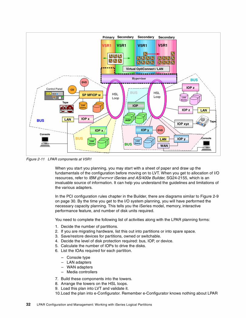
Figure 2-11 LPAR components at V5R1
When you start you planning, you may start with a sheet of paper and draw up the fundamentals of the configuration before moving on to LVT. When you get to allocation of I/O resources, refer to IBM ~ iSeries and AS/400e Builder, SG24-2155, which is an invaluable source of information. It can help you understand the guidelines and limitations of the various adapters.
In the PCI configuration rules chapter in the Builder, there are diagrams similar to Figure 2-9 on page 30. By the time you get to the I/O system planning, you will have performed the necessary capacity planning. This tells you the iSeries model, memory, interactive performance feature, and number of disk units required.
You need to complete the following list of activities along with the LPAR planning forms:
1. Decide the number of partitions.2. If you are migrating hardware, list this out into partitions or into spare space.3. Save/restore devices for partitions, owned or switchable.4. Decide the level of disk protection required: bus, IOP, or device.5. Calculate the number of IOPs to drive the disks.6. List the IOAs required for each partition.
– Console type– LAN adapters– WAN adapters– Media controllers
7. Build these components into the towers.8. Arrange the towers on the HSL loops.9. Load this plan into LVT and validate it.10.Load the plan into e-Configurator. Remember e-Configurator knows nothing about LPAR
V5R1 V5R1 V5R1V5R1
Primary Secondary SecondarySecondary
IOP xLAN
IOP yLAN
IOP z LAN
SP MFIOP w
LoadSource
IBM
Tape
CD
IOP y
LoadSource
IOP z
LoadSource
TapeIOP xyz
HSLLoop
HSLLoop
IOP x
LoadSource
Control Panel
01 B
Virtual OptiConnect / LAN
IOP
IASPBUS
BUS
BUS
BUS
BUS
Console
Console
WAN
DVD
DVD
Hypervisor
32 LPAR Configuration and Management: Working with iSeries Logical Partitions

2.2.2 Partitioning levels: Bus ownershipThere are two supported types of partitioning:
� Bus-level partitioning (dedicated bus)
Bus-level partitioning means a bus and all its attached IOPs and devices are dedicated to a single partition. If all partitions are fully partitioned at bus-level, separate devices are required for every partition (for example, alternate IPL devices like CD-ROM and tape). Bus-level partitions allow for:
– Simplified hardware management
– Better performance since SLIC does not have to call PLIC to queue commands for a bus
– Better problem isolation and, therefore, higher availability
� IOP-level partitioning (shared bus)
When you partition a bus at IOP level, you share the bus and divide up the I/O resources by IOP. There is always one partition that owns the bus. Since it is shared, other partitions can use this bus. Therefore, you can switch IOPs and their attached devices between partitions. IOP-level partitions allow for:
– Greater flexibility when partitioning I/O subsystems
– Potential cost reduction by eliminating some expansion units that are required to support additional buses
– Requires the use of Service tools menus to allocate/deallocate hardware resources between logical partitions
Starting with V5R1, you can dynamically change the bus ownership or usage. This does not require IPL anymore. When the primary partition is running V5R1, all secondary partitions (also the ones running V4R5) can take advantage of this functionality.
2.2.3 Bus ownershipBuses on the system can have a number of ownership status, but really they fall into two categories: dedicated and shared. With V5R1, a shared bus can be moved from one partition to another without IPL. An example of this is an external attached xSeries with an Integrated xSeries Adapter installed. The xSeries can be shut down, and the IOP can be moved between partitions using the Operations Navigator GUI.
There are two ways to allocate system buses to partitions. Depending on the requirements, there can be advantages allocating I/O resources to partitions using different types of bus allocation. The two types are:
� Shared buses� Dedicated buses
When a bus is designated as shared, a partition owns the bus, but allows other partitions to use IOPs that are attached to the bus.
When a bus is designated as a dedicated bus, the bus is owned by one partition, and all IOPs and associated IOAs on the bus are owned by that partition. When a bus is configured as dedicated, no dynamic resource movement of IOPs is allowed.
Dedicated bus allocation offers the following benefits:
� Better problem isolation between partitions since each bus and all the devices attached to that bus do not depend on other partitions
Chapter 2. Understanding logical partitioning 33

� Better performance since SLIC does not have to call PLIC to queue commands for a bus
Shared bus allocation on the other hand allows you to switch single IOPs between multiple partitions. This can help to reduce the cost of hardware required, but you must be careful with the IOAs that are configured under each IOP.
Starting with V5R1, you can dynamically move system buses between partitions. Changing bus ownership does not require IPL. However, this will only require the primary to be at V5R1. V4R4 and V4R5 secondary partitions can take advantage of this functionality. It is also available on all models that support logical partitioning.
2.2.4 IOP in logical partitionsIn reality, most customer will share some devices between systems, especially tape drive. For other devices, the recommended approach is to confine all hardware within a partition. The new #5078 top hat unit offers an excellent opportunity to provide a low-cost sharable bus.
Partitions do not support concurrent device sharing. That is, if a tape drive or CD-ROM is to be shared between partitions, it must “belong” to the partition that uses it. IOPs that are candidates for switching include:
� IOPs that control high cost devices (tape drives/libraries, CD/DVD)� IOPs that control low utilization devices and low demand devices (twinax console, ECS)
The advantages of switching IOPs and devices are:
� Reduced cost; only one device is required.� Fewer card slots are needed, in some cases.
The disadvantages of switching IOPs and devices are:
� It is inconvenient to schedule the use of switchable IOPs and devices.� Scheduling is possible; programmatic operations are possible with effort.� There is an increase in cost if a tower or part of a tower is required to be shared.
Before you implement a switchable IOP and other devices, you should also consider other possible alternatives. To share devices among partitions, you can apply the same techniques that are used to share devices among separate physical servers:
� Use multiple IOPs, one in each partition, for devices that support multiple connections (some high end tape drives).
� Use multiple IOPs, one in each partition, and use a switch box for devices that only support single connections (printers or some high-end tape drives).
� Use multiple IOPs and multiple devices in each partition for a self-contained solution (internal removable media devices).
Note: Regardless of the type of partitioning selected, the primary partition controls the availability of each bus on the system. If a secondary partition owns a shared bus, and that partition is powered off, all IOPs on that shared bus dedicated to other partitions can still be used.
Tip: For external tape (for example, 3590), it is possible to have one tape device, but separate IOPs for each partition that will use it. A partition that requests the use of the device receives a “busy” indication if it is in use by another partition.
34 LPAR Configuration and Management: Working with iSeries Logical Partitions

2.2.5 MemoryMemory is rather interesting. Unlike processors and I/O, it’s difficult to visualize the allocation. You can think of it being similar to memory allocation of subsystems on a single server.
Primary partitions need a minimum of 256 MB of memory. The minimum memory of V5R1 secondary partitions is 128 MB. For V4R4 and V4R5 secondary partitions, the minimum remains at 64 MB. Linux also has 64 MB minimum. The minimum values dictate what is required to restart the partition. If the minimum value is not met for all logical partitions, only the primary will restart.
You size the memory as if it were a single system. Then add them all up to find the total system memory. Don’t skimp on memory since most new applications are very memory hungry. You can take advantage of the dynamic resource movement if there are particular requirements when other partitions are not heavily used.
You can specify a memory minimum value as low as 0 to shut a partition down and use resources elsewhere. A value of 0 in any partition creates a non-functioning partition. If the primary partition is restarted after the secondary partition is set to 0, then a system restart is required when the secondary memory value is changed. If the changes are made to the memory within the same primary restart, then a system restart is not required to make changes to the memory allocations.
To move memory, you have to establish a minimum and maximum range within which you can move the resource without needing to restart the logical partition. Changing the maximum value requires a system restart. Changing the minimum value only requires you to restart the partition.
When you move memory out of a running partition, it is not an instantaneous move. The system must move any pages that occupy the memory to be moved, out to disk or another part of memory. This could take a while on busy systems. The memory is taken from the base pool and moved into the base pool. You should ensure the memory is available on the source system. When the moved memory arrives at the target in the base pool, you must arrange to allocate the memory to the correct storage pool of operation.
We recommend that you specify the maximum value close to the amount of memory that the partition will be assigned. Specifying a maximum value higher than what is needed for the partition wastes valuable memory resources. When you dynamically move memory to a logical partition, depending on partition activity or available memory, the allocated amount will not exceed the runtime minimum until the partition activity has ended or you restart the partition.
Runtime values are based on memory that the partition needs to complete an assigned task. If you want to change the runtime minimum or need to configure the logical partition back to the minimum, you need to restart the partition.
2.2.6 Interactive performanceEvery physical system is purchased with a specific level of interactive performance. This interactive performance enables you to run jobs that require user interaction (5250 type jobs) in contrast to batch jobs that require no user interaction (or server jobs). Each partition has a minimum requirement for the amount of interactive performance. To move interactive performance, you have to establish a minimum and maximum range within which you can move the resource, without needing to restart the logical partition.
Chapter 2. Understanding logical partitioning 35

If you change the either the minimum or maximum value, you have to restart the entire partition. You can specify an interactive performance minimum value equal to the minimum amount of interactive performance needed to support the logical partition. The minimum interactive performance that must be allocated to a partition is 1.5% of the total CPW available in the partition.
This example demonstrates how the interactive requirements can impact your hardware choices. Consider an existing 730-2068 with interactive FC 1506. This machine is rated at 2890 CPW and 70 Interactive CPW. If this machine were partitioned with seven processors allocated to a single partition, the capacity for the partition would be:
((2890 / 8)*(7) = 2528.75
The minimum amount of Interactive CPW required to be allocated to the partition would be:
(.015 * 2528.75)= 37.9
This number is 54% of the total available interactive resource for the system.
Things change when we look at upgrading this system to a Model 830-2403 with interactive FC 1531. This machine is rated at 7350 CPW and 70 Interactive CPW. Assuming we keep seven processors in the partition, the new capacity is:
((7350 / 8) * (7) = 6431.25
The minimum amount of interactive CPW required to be allocated to the partition would be:
(.015 * 6431.25)=96.4
This number is now greater than the available resource for the entire system (and we haven’t allocated any to the other partition). This would require an interactive feature upgrade to the IFC 1532, which provides a capacity of 120 Interactive CPW. This move also forces a software tier upgrade from the P40 to P50 Group.
The maximum value must be less than the amount of interactive performance available on the system. The maximum interactive performance depends on the number of processors in a partition.
2.2.7 Console optionsThere are three supported types of consoles on an iSeries. This section briefly explains each console type. For further details, see 6.1, “All about consoles on iSeries” on page 104.
Twinax consoleA twinaxial console is a non-programmable terminal that uses the original 5250 data stream to connect to a workstation controller. This type of connection is easy to set up because you have a direct cable attachment, and no additional software is needed. All the functionality is in the terminal’s logic. You need to specify address 0 on the terminal and connect it to port 0 of the workstation controller in the iSeries.
The disadvantage of this is that this limits the console access to one physical screen that is not capable of anything else. This also requires one terminal per machine or partition and also needs physical access to the terminal. The twinax console does not provide remote access to your iSeries.
Important: When planning to partition a new server or upgrade an existing partitioned server, you must use careful planning to ensure sufficient Interactive CPW capacity is available.
36 LPAR Configuration and Management: Working with iSeries Logical Partitions

Over time, this technology will gradually be phased out as customers and technical support people move to the newer GUI interface that allows remote access, and with the LAN console, consolidates several consoles on one PC.
But at present, the twinax console remains the most reliable method to access the majority of low-level system functions. Twinax is frowned upon by many customers new to the iSeries. However, if you look at most of the “other” servers around, they all have a terminal access mode that is as equally displeasing as a green screen.
Operations Console Operations Console allows a personal computer (PC) to become a local or remote console to your iSeries server. This eliminates the need for a twinaxial connection and allows a system administrator to watch the system from another location. The iSeries supports a directly-attached, full-function 5250 PC console that includes a graphical control panel application. The user interface of the control panel application resembles its hardware counterpart. The console emulator application (PC5250) serves as the console “device” of the iSeries. The graphical control panel application permits remote entry of most of the functions supported by the hardware control panel mounted on the front of iSeries server units. Control panel functions such as power up/down, re-IPL, mode changes, etc. are supported.
The console and control panel applications can be used together or separately, but each requires its own direct cable attachment to an iSeries server. Each cable must be purchased separately from IBM for the iSeries model being used. Both cables are only available in a single length of 6 meters.
In an LPAR environment, Operations Console is not a very acceptable offering. You would need a PC for every partition. It would be a good alternative to the twinax console managing the primary partition.
LAN-attached Operations ConsoleWith V5R1, Operations Console has been enhanced to enable connections or console activities across a local area network (LAN). A single PC can have multiple connections to multiple iSeries servers and can be the console for multiple iSeries servers.
An example is a logically partitioned server that uses the same PC as the console for all partitions. Since each partition is considered a separate iSeries server, you need a separate connection to the partition that you want to be the console. The LAN console allows multiple connections to a single iSeries server, but only one PC can have control of an iSeries server at a time.
Enhanced authentication and data encryption provide network security for console procedures. LAN console connectivity uses a version of SSL that supports device and user authentication but without using certificates.
You really need to be confident with the LAN console before you implement it as your sole console access to the server.
Important: LAN console is the techie’s console of choice for the remote management of secondary partitions. Consider these words of caution: On small logically partitioned systems with limited slots, it may be more effective to have a shared bus/IOP with a switchable twinax console.
Chapter 2. Understanding logical partitioning 37

Communication optionsThere are a few new things in the intersystem communications arena. Virtual Ethernet LAN is a brilliant addition to the “internal” and secure connection method. HSL OptiConnect is another addition for those customers waiting for an SPD OptiConnect replacement.
Partitions on a server can dynamically (without an IPL) be added or removed from the virtual OptiConnect or HSL OptiConnect network. A notification of the access change is sent to the partition. The partition either resets its connection and removes itself from the network or connects into the network as appropriate. The virtual LAN will emulate a 1Gb Ethernet interface to communicate between partitions.
Logical partitions can use any of the following communication methods to interact with other partitions or servers. The type of communication option or options that you use will depend on your business needs. You can use any combination (or none) of these communication methods within a partition as long as the server contains the appropriate hardware:
� Virtual Ethernet LAN
Virtual LAN enables you to establish communication via TCP/IP between logical partitions. Each partition can define up to 16 virtual LAN ports. Partitions defined to use the same port can communicate through that link. Virtual LAN can be used without any additional hardware or software.
� SPD OptiConnect
SPD OptiConnect allows a partition to communicate with another server or another partition that also has the OptiConnect hardware. Any partition that uses OptiConnect must have the OptiConnect hardware on a dedicated bus in the partition. The OptiConnect hardware cannot be on a shared bus. In addition, you must purchase (a priced optional feature) OptiConnect for OS/400 software.
� Virtual OptiConnect
Virtual OptiConnect allows one partition to communicate with another partition if both partitions have virtual OptiConnect enabled. Any partition can use virtual OptiConnect. You can enable virtual OptiConnect at any time. When you enable or disable virtual OptiConnect, the changes take effect immediately. No additional hardware is required. However, you must purchase (a priced optional feature) the OptiConnect OS/400 software to use this feature.
� HSL OptiConnect
High Speed Link (HSL) OptiConnect provides high speed system-to-system communication. HSL OptiConnect is a partition-to-system communication link. This cannot be used for partition to partition communication. It requires standard HSL cables, but no additional hardware is required. You must purchase (a priced optional feature) OptiConnect for OS/400 software before you can use this feature.
� HSL OptiConnect fabric
This is not really a communication method; it is used to connect clusters together.
2.2.8 Upgrade considerationsWhen upgrading hardware containing logical partitions, you must carefully consider the possible impact of new features and new versions of OS. For example, if you buy a new server as an upgrade, remember hardware features have a particular OS level of support. The #2766 can be run on 8xx hardware, but is only supported in a V5R1 partition.
38 LPAR Configuration and Management: Working with iSeries Logical Partitions

Consider the case where you were going to buy an 8xx and consolidate a number of systems from previous releases. You would need hardware that supported these releases. For example, the new disk IOA #xxxx could not be used in these previous-release partitions. You would have to install #yyyy disk IOA.
In some cases, you may consider converting existing expansion towers to new models.
2.3 Software requirementsDuring the initial planning phase, many meetings and discussions take place. Decisions made during these meetings dictate the software version and release required to support the configuration selected.
Minimum software requirementsThis redbook is aimed at a V5R1 implementation for the primary partition. Therefore, the minimum software requirement for the primary partition is V5R1. You can run V4R4 in a secondary partition, but the primary partition would then be V4R5. Systems with logical partitions have the ability to support more than one version of OS/400.
2.3.1 OS/400 release support for the n-way Sx0, 6xx, and 7xx modelsIn general, Sx0, 6xx, and 7xx hardware runs all software versions beginning with V4R4. In addition, when this hardware runs V4R4 in the primary, V5R1 is also supported (P+2) in a secondary partition. These models must have two or more processors and are not capable of supporting the shared processor pool. See Table 2-6.
Table 2-6 n-way AS/400 models (Sx0, 6xx, and 7xx)
2.3.2 OS/400 release support for the n-way 8xx modelsThe 8xx hardware can support release V4R5 in a primary or secondary partition, as long as the 8xx model has more than one processor. The 8xx models with a single processor can only support V5R1 in all partitions. See Table 2-7.
Important: The current logical partition strategy is to support up to three different releases on the same system. Using the primary partition as the reference release (denoted as P), the strategy is to support secondary partitions of one previous release of OS/400 (P - 1), the same release as the primary (P), and a future release (P + 1).
Primary Secondary (P-1) Secondary (P) Secondary (P+1) Secondary (P+2)
V4R4 V4R31 not supported V4R4 V4R5 V5R12
V4R5 V4R4 V4R5 V5R1 VxRy not supported
V5R1 V4R5 V5R1 VxRy VnRm not supported
Notes:1. V4R3 was not enabled for LPAR.2. P+2 is supported by exception only for this release when primary is at V4R4 on AS/400 models
only.
Chapter 2. Understanding logical partitioning 39

Table 2-7 iSeries n-way 8xx models
2.3.3 OS/400 release support for the new 270 and 8xx modelsThe new 270 (processor feature codes 2431, 2432, 2434, 2452, 2454) and new 8xx models (processor feature codes 0150, 0151, 0152, 2435, 2436, 2437, 2438, 2456, 2457, 2458) need V5R1 as an enabling release. The new n-way models support V4R5 on a secondary partition. However, to partition a uni-processor model, you need to run V5R1 as well in the secondary partitions.
Table 2-8 New iSeries Models 270 and 8xx
2.3.4 Available LPAR function listed by releaseThe capabilities available in OS/400 logical partitions vary with each version of the operating system release. The primary partition release determines the base logical partition capability of the entire system. To use a specific capability, a secondary partition OS/400 release must also support the function. Use Table 2-9 to determine the available logical partition function by OS/400 release.
Table 2-9 Overview LPAR functions
Primary Secondary (P-1) Secondary (P) Secondary (P+1)
V4R4
V4R5 V4R4 not supported V4R5 V5R1
V5R1 V4R5 V5R1 VxRy
Note: iSeries servers require OS/400 V4R5 as an enabling release as a minimum. Therefore, V4R4 is not support in a primary or secondary partition.
Primary Secondary (P-1) Secondary (P) Secondary (P+1)
V4R4 not supported
V4R5 not supported
V5R1 V4R5 V5R1 VxRy
LPAR function V4R4 V4R5 V5R1
Maximum partitions 12 or the number of processors on the system, whichever is less.
12 for 6xx, 7xx, Sx0 models; 24 for 8xx models; or the number of processors on the system; whichever is less.
12 for 6xx, 7xx, Sx0 models; four times the number of system processors or 32 for 8xx models; whichever is less.
Processors � Static: Requires a restart of the partition to change.
� Dedicated to a partition.
� Static: Requires a restart of the partition to change.
� Dedicated to a partition.
� Dynamic: May be changed without IPL of partition.
� May be shared among multiple partitions.
Memory Static: Requires a restart of the partition to change.
Static: Requires a restart of the partition to change.
Dynamic: May be changed without IPL of partition.
40 LPAR Configuration and Management: Working with iSeries Logical Partitions

2.3.5 Application workload analysis Once the decision is made to partition a server and an understanding the hardware and software requirements for logical partitions is acquired, you should focus on the workload demand in each partition.
Each secondary logical partition on an iSeries server acts as an independent system on the server. However, these partitions maintain a dependency on the primary partition. The primary partition must be running to keep each secondary partition on the system accessible.
With that in mind, deciding on what runs in the primary partition is important to maintain stability throughout your system. If you have multiple production environments on the same server, we recommend that you partition the primary partition with the minimum amount of hardware resources and use the primary only for applications that are stable.
Interactive performance
Static: Requires a restart of the partition to change.
Static: Requires a restart of the partition to change.
Dynamic: May be changed without IPL of partition.
Virtual Ethernet LAN Not supported. Not supported. � Dynamic: May be changed without IPL of partition.
� Up to 16 independent Gb Ethernet networks (per partition).
Virtual OptiConnect � Static: Requires a restart of the entire system to change.
� Single network.
� Static: Requires a restart of the entire system to change.
� Single network.
� Dynamic: May be changed without IPL of partition.
� Single network.
HSL OptiConnect Not supported. Not supported. � Dynamic: May be changed without IPL of partition.
� May be shared among multiple partitions.
� Single network.
I/O partitioning � Bus- or IOP-level partitioning.
� IOP may be switched among partitions dynamically.
� Bus ownership or bus usage (shared or dedicated) changes require a restart of the whole system.
� Bus- or IOP-level partitioning.
� IOP may be switched among partitions dynamically.
� Bus ownership or bus usage (shared or dedicated) changes require a restart of the whole system.
� Bus- or IOP-level partitioning.
� IOP may be switched among partitions dynamically.
� Bus ownership or bus usage (shared or dedicated) changes occur dynamically.
Guest partition Not supported. Not supported. Linux.
LPAR function V4R4 V4R5 V5R1
Chapter 2. Understanding logical partitioning 41

Secondary partitions can handle different types of workload demands without causing down time on the server. You can perform new PTF updates or new release testing on secondary partitions before you install these packages to the primary partition. Applications that require high availability should be running in a secondary partition to minimize problems with the applications. You can also use the secondary partition to backup data on another partition on the server. This way if data is lost, the secondary partition responsible for backing up the information can be used without causing delays to your business schedule.
To find out more about sizing and capacity planning of logical partitions on iSeries, see Capacity Planning for Logical Partitioning on the IBM ~ iSeries Server, SG24-6209.
42 LPAR Configuration and Management: Working with iSeries Logical Partitions

Chapter 3. Planning for logical partitions
To assist with your system planning, we created some examples of partitioned systems. This chapter begins by explaining some of the tasks and information to be gathered. Then it goes through solution-based examples. This chapter looks at the following topics:
� “Planning examples” on page 46� “Complexity” on page 56� “LPAR configuration and order process” on page 60� “Conventions in LPAR” on page 61
3
© Copyright IBM Corp. 2002 43

3.1 Planning and data collectionNow that you know the partitioning choices and options available as discussed in Chapter 2, “Understanding logical partitioning” on page 15, it’s time to start gathering information.
In the initial planning and data collection phase, you should consider the following items when planning to logically partition a server. All gathered information must be documented so that the information is available for input to subsequent planning phases and as a reference during implementation. These documents should also be maintained after the implementation as part of the customer’s systems management process to provide an accurate “as installed” view of their partitioned server environment.
To complete the LPAR planning process, you must decide how you want to set up the logical partitions. You must gather the following information, which is most easily captured on a worksheet. We recommend that you use the Logical Partition Hardware Planning Worksheet found in Appendix A, “LPAR planning worksheets” on page 343. You can find a more recent example on the LPAR home page at: http://www.ibm.com/eserver/iseries/lpar
Here’s what you need and need to do:
1. For each partition, determine:
– Performance expectations
• Response time• Batch runtime• Interactive performance
– Growth
• Disk storage requirements• Transaction workload• New application requirements/retirement of old applications
– Partition availability to include
• Save/restore• Batch window• Business impact of scheduled/unscheduled outages
2. Perform the proper capacity planning for each logical system, new or consolidated, to determine the number of partitions needed and the size of each.
Capacity planning is done to determine the system resources necessary to achieve the desired performance for a given volume of business transactions. A consultant or specialist in capacity planning must first determine the relationship between business transactions and system transactions. Once this is determined, any estimated changes in the volume of business can be used to predict changes in the amount of system resource needed. The key resources to focus on are: CPU, main storage, and disk storage. For more information, see Capacity Planning for Logical Partitioning on the IBM ~ iSeries Server, SG24-6209.
For each partition, document the following characteristics:
� Total performance in partition (in CPW)� Interactive performance (in CPW)� Main storage (in Mb)� Disk capacity and protection level� Type of console being used (twinax, Operations Console, or LAN console)� The number of token ring or Ethernet cards� Tape devices� Communication IOPs (V24, X21, etc.)
44 LPAR Configuration and Management: Working with iSeries Logical Partitions
� The number of Integrated xSeries Servers� The number of twinax workstation controllers� Whether you want Electronic Customer Support� Whether you want to run Linux in a secondary partition� DVD-ROM or CD-ROM unit for installing new releases� Software release currently installed source system� Software release desired to be installed in partitions of target system� IBM Software availability if not installed� All ISV installed code is supported and available for target release
Next you need to gather the following information from the systems:
� Source system
– Performance data using either the Collection Services or STRPFRMON collection methods. Data should represent peak utilization time periods preferably with period (month or quarter end) workloads captured if possible.
– Machine configuration listing that is current and accurate. To get this information, sign on to the system (STRSST) and access Hardware Service Manager (HSM).
� Target system
– Marketing configurator output for additional hardware features. The configurator will be used in the following circumstances:
• MES model upgrade of the source system• MES of source system without processor upgrade• New target machine order
3.1.1 Hardware and software assessment and system designThis is the most critical phase. It assumes that you have considerable knowledge and skills of AS/400 and Series hardware, software, and LPAR implementation rules, as well as a complete understanding of the customer’s system requirements. This knowledge, accompanied by the information gathered in the planning phase, provides the necessary elements to begin designing the partitioned system, verifying the hardware configuration, and creating a detailed implementation plan.
The LPAR Validation Tool (LVT) is the recommended tool to use when the design phase begins. This tool gives the user the capability to place hardware resources (IOP/IOA/DASD) into the specific slots and bays of the target machines and to use the tools’ rules-based logic to verify the configuration. You can find more information and examples in Chapter 12, “Basics of using the LPAR Validation Tool (LVT)” on page 325.
You will use the model created during capacity planning and attempt to recreate this within LVT. This may require additional resources above those considered in the capacity planning exercise. You should not reduce the resources below the capacity plan.
The completed LVT document, when compared to the combined resource list (the combination of the source machines hardware and the additional hardware from the configurator output), will allow you to identify whether any hardware discrepancies exist (shortage or overage of hardware) to achieve your desired partition configuration within the hardware limits of your iSeries server.
This may be an iterative process, requiring the server to be re-modelled as a result of the proposed configuration.
Chapter 3. Planning for logical partitions 45

3.1.2 Planning the implementationDuring this final planning phase, alternative upgrade methods are reviewed. Methods are available that allow LPAR to be implemented more quickly to prevent the reloading of system data. These options could save significant time where large systems or systems with large amounts of storage are involved.
Once the strategy is determined, a detailed task plan can be developed. This plan provides information concerning each major step of the upgrade and partitioning process, along with the identity of the individual responsible for performing each task. Remember that some tasks can be performed prior to the major upgrade day or weekend. These tasks must also be included in the implementation plan.
Again the upgrade plan may affect the system performance, so any changes to configurations here should be remodelled to see the effect. This may drive additional hardware or an alternate upgrade method.
3.2 Planning examplesThe following sections describe the planning process prior to ordering and implementing a partitioned system/system upgrade. These two sections are common to all scenarios.
Initial planning and data collection phaseDuring this phase, all data outlined in 3.1, “Planning and data collection” on page 44, must be collected and documented on the planning worksheets. The information must include the customer’s requirements for both partitions to be created.
The performance data and capacity planning analysis will depend on data provided by the customer, but it must be completed prior to configuration and marketing order processing.
Once this phase is completed, all customer requirements for partition size, application program requirements, system availability/business interruption, hardware, and software for each partition will be identified and documented on LPAR planning worksheets as input to the next phase.
Hardware/software assessment and system design phaseWith the required initial planning completed, the time has come to begin the design phase of the planning process. Once the hardware and software requirements are identified, they can be compared to the existing hardware and software inventory. If items are determined to be unavailable from existing inventory, marketing configurations can be run to add the necessary hardware to meet the partitioning requirements.
The combination of existing hardware and proposed hardware can be built into the planning worksheets or the LVT tool. These completed tools must be reviewed and validated by Business Partner, IBM Technical Support, or other LPAR trained technical support personnel. If the capacity planning analysis was not finished prior to starting this phase, it would be appropriate to follow-up now to determine the status of the analysis.
If additional hardware is to be ordered to meet the partitioning requirements, we do not recommend continuing with the order until the results of the analysis are understood.
46 LPAR Configuration and Management: Working with iSeries Logical Partitions

At the end of this phase, the beginning of a detailed implementation plan begins to take shape. The LVT and worksheets provide a hardware installation and implementation guide that will be input to the customer’s systems management plan. These documents will also provide the detailed card placement information required by the IBM Service Support Representative (SSR) to correctly locate the system hardware to allow the desired partition configuration to be created.
You must know all information required to complete the LPAR configuration screens (or GUI wizard) prior to completing the system design phase. At this time, you should also have final agreement on the hardware and software requirements, as well as concurrence from the customer. In addition, you should also perform a systems assurance review.
3.2.1 Example 1: Implement LPAR on a new/existing Model 270In this example, a customer desires to have their existing system partitioned to provide a small primary partition and a secondary OS/400 partition. The installed system is a Model 270 and came preloaded with V5R1. All existing hardware resources are assigned to the primary (only) partition. We make the following assumptions:
� Primary partition will host an existing small workload.
� Secondary partition will host a customer’s new workload.
� Reloading the primary will not be necessary, but initial load of the secondary will require a complete software load.
� The machine has sufficient storage and resources to support second partition. The existing workload will perform adequately in the small primary.
This scenario is outlined in Figure 3-1.
Figure 3-1 Upgrade example 1
Planning the implementation phaseThis phase develops a plan that should include the major steps to be taken during the LPAR configuration activities. You should develop the plan after you review alternative methods to achieve the desired result. Different procedures may result in longer/shorter implementations.
Example 1: 270 LPAR 2 Partitions P0 Small - P1 Normal Secondary
Existing V5R1 Model 270 with 5075 Expansion tower
HSL
Target V5R1 270 Thin Primary P0 Secondary P1
HSL
Chapter 3. Planning for logical partitions 47

The key steps in this example implementation are:
� Pre-upgrade tasks:
a. Inventory all hardware. b. Inventory all software.c. Order and install the latest cumulative PTF package.d. Print the system configuration and system values.
� Implementation tasks:
a. Complete system saves (Option 21) prior to start.
b. System IPL to DST.
c. Remove enough configured DASD, IOPs, and IOAs to support a secondary partition, (sufficient disk space must be available on remaining drives to hold data to be moved off the removed disk drives).
d. Verify that adapters are available to support new load source, console, alternate IPL, and save restore requirements for the secondary partition.
e. IBM SSR, following the LVT and worksheet diagrams, will place DASD, IOPs, and IOAs in the assigned slots. External tape and secondary partitions’ console are installed as required.
f. IPL the machine and verify the hardware.
� Partitioning tasks:
a. Machine manually IPL to DST.b. Change the processors from dedicated to shared.
• Processors (shared for this example) • Memory• Interactive CPW • Minimum and Maximum value ranges• Buses (dedicated or shared)• IOPs (dedicated or shared)• Load Source units• Alternate IPL• Console
c. Create and name Partition 1. d. Allocate resources to P1.e. IPL Model 270.f. Start the secondary with D Manual IPL.g. Install V5R1 SLIC, OS/400, LPPs, and cumulative PTF package.h. Ensure that the hardware configuration is as required and document it.i. Ensure that DASD protection is active for both partitions.j. Customer should load the desired ISV programs and data.k. Save (Option 21) the complete P0 and P1 partitions.
3.2.2 Example 2: Implementing LPAR on a 720 with MES upgrade to an 830In this example, a customer desires to have their existing system upgraded and partitioned to provide a dedicated processor to the primary partition and a secondary OS/400 partition. The installed system is a non-partitioned Model 720 where all existing hardware resources are currently assigned to the primary (only) partition, and OS/400 V4R5 is the loaded software version. In this scenario, we could now covert the existing expansion towers to 5074 expansion towers.
48 LPAR Configuration and Management: Working with iSeries Logical Partitions

We make the following assumptions for this example:
� Primary will remain at V4R5; the secondary partition will be V5R1.� Primary partition will host the existing workload.� Secondary partition will host customers’ new workload.� Reloading the primary will not be necessary, but an initial software load of the secondary
is required.
This scenario is outlined in Figure 3-2.
Figure 3-2 Upgrade example 2
Planning the implementation phaseThis phase develops a plan that should include the major steps to be taken during the hardware installation and LPAR configuration activities. The plan should be developed after you review alternative methods to achieve the same result. Different procedures may result in longer or shorter installations times.
The key steps in this example implementation are:
� Pre-upgrade tasks:
a. Inventory all hardware.b. Inventory all software.c. Complete physical planning, and ensure that power is installed.d. Print the system configuration and system values.
Note: Prior to the marketing configuration being ordered, we recommend that you review it to ensure that no V5R1 hardware is included in the order that would be assigned to the primary partition, since it will be installed with V4R5.
Example 2: 720 to 830 MES Upgrade - LPAR 2 Partitions Dedicated Processors P0 & P1
HSL
Target SystemNew 830 CEC
Modified 720CEC Becomes Migration Tower IExisting V4R5 720 with
5065 Expansion Towers
Source System
SPD
SPD
Chapter 3. Planning for logical partitions 49

� Upgrade tasks:
a. Complete system saves (Option 21) prior to beginning the hardware upgrade.
b. IBM SSR performs upgrade according to Customized Upgrade Installation Instructions (CUII) including load source migration.
c. IBM SSR, following the LVT and worksheet diagrams, will place DASD, IOPs, and IOAs in the assigned slots. External tape and secondary partitions console should be installed as required.
d. IPL the machine and verify the hardware.
� Partitioning tasks:
a. Machine manually IPL to DST.b. Deallocate and reallocate resources for P1:
• Processors (dedicated for this example) • Memory• Interactive CPW • Minimum and Maximum value ranges• Buses (dedicated or shared)• IOPs (dedicated or shared)• Load Source units• Alternate IPL• Console
c. Create and name partition 1.d. IPL Model 830.e. Start the secondary with D Manual IPL.f. Install V5R1 SLIC, OS/400, LPPs, and cumulative PTF package to secondary partition.g. Ensure that hardware configuration is as required and document it.h. Ensure that DASD protection is active for DASD in both partitions.i. Customer should load desired ISV programs and data.j. Save (Option 21) the complete P0 and P1 partitions.
3.2.3 Example 3: Implementing LPAR on 730 to 830 MES upgrade with a thin primary
In this example, a customer with a Model 730 wants to upgrade their existing system to a Model 830 and implement a secondary partition. They want a thin primary and to run their current production in the secondary partition.
In this scenario, we could now covert the existing expansion towers to 5074 expansion towers.
We make the following assumptions for this example:
� Both partitions will be V5R1.� Primary will host thin management partition.� Secondary partition will host the customer’s existing workload.� Loading the primary is necessary but no reload of a secondary is required.
This scenario is outlined in Figure 3-3.
50 LPAR Configuration and Management: Working with iSeries Logical Partitions

Figure 3-3 Upgrade example 3
Planning the implementation phaseThis phase develops a plan that should include the major steps to be taken during the hardware installation and LPAR configuration activities. You should develop the plan after you review the alternative methods to achieve the same result. Different procedures may result in longer or shorter installations. This plan only documents the major steps and does not attempt to cover all possibilities.
The key steps in this example implementation are:
� Pre-upgrade tasks:
a. Inventory all hardware.b. Inventory all software.c. Upgrade the installed Model 730 V4R5 to V5R1 with the latest cumulative package.d. Complete the physical planning and ensure that power has been installed.e. Print the system configuration and system values.f. Install the 830 and IPL to DST g. Install OS/400 V5R1 on the 830.
� Upgrade tasks:
a. Complete the system saves (Option 21) of 730 prior to beginning the hardware upgrade.
b. IBM SSR performs the hardware upgrade according to the Customized Upgrade Installation Instructions (CUII).
• The upgrade includes moving hardware from the 730 CEC to provided Migration Tower II (FC5077).
• IBM SSR must not perform load source migration. Reload is required if this step is ignored.
Example 3: 730 to 830 MES Upgrade - LPAR 2 Partitions P0 Thin - P1 Thick
New 5077 Migration Tower II Shipped with upgrade
HSL
SPD
Target System
New 830 CEC
SPD
Source System
Existing V4R5 730 with5073 Expansion Towers
Chapter 3. Planning for logical partitions 51

c. IBM SSR, following the LVT and worksheet diagrams, will place DASD, IOPs, and IOAs in the assigned slots. External tape and secondary partitions console are installed as required.
d. IPL the machine and verify the hardware.
e. Numerous error messages will be encountered due to multiple load source drives sensed during IPL.
� Partitioning tasks:
a. Machine manually IPL to DST.b. Create a secondary P1 partition.c. Resolve resource name conflicts for P1.d. Re-allocate resources to P1.
• Processors (dedicated for this example) • Memory• Interactive CPW • Minimum and Maximum value ranges• Buses (dedicated or shared)• IOPs (dedicated or shared)• Load Source Disk (load source from 730 moved to migration tower)• Alternate IPL• Console
e. IPL the 830.f. Ensure that hardware configuration is as required and document it.g. Ensure that desired DASD protection is active for both partitions.h. Save (Option 21) the complete P0 and P1 partitions.
3.2.4 Example 4: Implementing LPAR on an existing 830 with a thin primaryIn this example, a customer with an existing Model 830 wants to implement a secondary partition. They want a thin primary and will run production in the secondary partition. This should become a common scenario, now that V5R1 partial processor support will allow minimal resources be dedicated to the primary managing partition.
We make the following assumptions:
� Both partitions will be at V5R1.
� Primary partition will host the thin managing partition.
� Secondary partition will host the customer’s existing workload.
� Sufficient additional hardware is ordered and available to support additional load source for the primary partition.
� Initial load of primary is required, but the current production environment will not be reloaded.
This scenario is outlined in Figure 3-4.
Attention: Due to the complexity of this scenario, not all steps are provided in this document. This scenario requires the removal of the existing load source DASD and assumes the availability of disk slots in another storage location that supports a load source drive. New drives will be installed in the originals slot. You should approach planning for this scenario with caution, since the planning will be machine specific.
52 LPAR Configuration and Management: Working with iSeries Logical Partitions
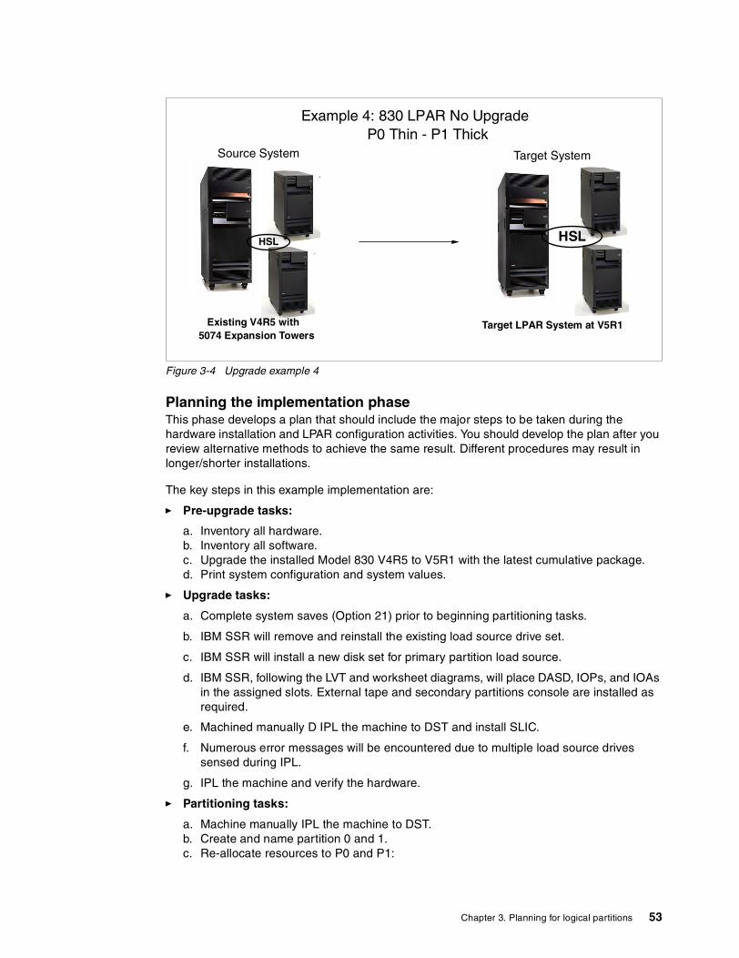
Figure 3-4 Upgrade example 4
Planning the implementation phaseThis phase develops a plan that should include the major steps to be taken during the hardware installation and LPAR configuration activities. You should develop the plan after you review alternative methods to achieve the same result. Different procedures may result in longer/shorter installations.
The key steps in this example implementation are:
� Pre-upgrade tasks:
a. Inventory all hardware.b. Inventory all software.c. Upgrade the installed Model 830 V4R5 to V5R1 with the latest cumulative package.d. Print system configuration and system values.
� Upgrade tasks:
a. Complete system saves (Option 21) prior to beginning partitioning tasks.
b. IBM SSR will remove and reinstall the existing load source drive set.
c. IBM SSR will install a new disk set for primary partition load source.
d. IBM SSR, following the LVT and worksheet diagrams, will place DASD, IOPs, and IOAs in the assigned slots. External tape and secondary partitions console are installed as required.
e. Machined manually D IPL the machine to DST and install SLIC.
f. Numerous error messages will be encountered due to multiple load source drives sensed during IPL.
g. IPL the machine and verify the hardware.
� Partitioning tasks:
a. Machine manually IPL the machine to DST.b. Create and name partition 0 and 1.c. Re-allocate resources to P0 and P1:
Example 4: 830 LPAR No Upgrade P0 Thin - P1 Thick
HSL
Source System
Existing V4R5 with 5074 Expansion Towers
HSL
Target System
Target LPAR System at V5R1
Chapter 3. Planning for logical partitions 53

• Processors (shared for this example) • Memory• Interactive CPW • Minimum and maximum value ranges• Buses (dedicated or shared)• IOPs (dedicated or shared)• Load source units• Alternate IPL• Console
d. IPL 830e. Start the secondary with D Manual IPL.f. Install V5R1 SLIC, OS/400, and cumulative PTF package.g. Ensure that hardware configuration is as required and document it.h. Ensure that desired DASD protection is active for both partitions.i. Customer load desired LPP ISV programs and data.j. Save (Option 21) complete P0 and P1 partitions.
3.2.5 Example 5: Implementing a shell LPAR as part of an LPAR configurationIn this example, a customer wants to create a shell partition on their existing Model 270. This scenario is relatively simply from a planning and implementation point of view. The purpose of creating a shell is to potentially prevent having to IPL the primary partition to activate a secondary partition once its definition is completed in the future.
The only resource required to be defined at the time of creating the shell partition is main storage. The absolute minimum required is 64 MB (which is the minimum memory to support a V4R5 partition) to support a V5R1 partition; a minimum of 128 MB is required to be available in the unassigned hardware pool. Therefore, you must reserve at least this amount and set the minimum and maximum memory values that would support the actual amount desired in the partition. Remember that setting the maximum value unnecessarily high has the affect of reserving a percentage of that amount in the current configuration. This memory will not be effectively used by the active partitions until the secondary definition is completed and activated.
We make the following assumptions:
� Both partitions will be V5R1, thereby requiring 128 MB of memory.� Primary partition will remain unchanged.
This scenario is outlined in Figure 3-5.
54 LPAR Configuration and Management: Working with iSeries Logical Partitions

Figure 3-5 Upgrade example 5
Initial planning and data collection phaseRemember, the creation of a shell only requires main storage to be available. There are no requirements at this time to have the necessary hardware installed to actually support the secondary partition.
The requirements to plan for an LPAR implementation, however, must still be performed prior to successfully completing the implementation of LPAR for this example. It would be possible to use the information and planning section from 3.2.1, “Example 1: Implement LPAR on a new/existing Model 270” on page 47, to complete this requirement.
Planning the implementation phaseThis phase develops a plan that should include the major steps to be performed during the LPAR configuration.
The key steps in this example implementation are:
� Pre-upgrade tasks:
a. Verify the availability of the main storage.b. Print the system configuration and system values.
� Upgrade tasks:
a. Complete system saves (Option 21) prior to starting the hardware upgrade.
� Partitioning tasks:
a. Machine manually IPL to DST.b. Create and name partition 0 and shell secondary. c. Allocate resource to shell: Memory.d. IPL the 270.e. Save (Option 21) the primary partition.
1. Only main storage must be allocated to create shell2. 128 MB minimum to support V5R1 secondary
Example 5: 270 LPAR Create Shell Partition
Existing V5R1 Model 270 with 5075 Expansion tower
HSL
Target V5R1 270 Primary P0
HSL
SHELL 128 MB
Chapter 3. Planning for logical partitions 55

3.3 ComplexitySetting up partitions brings a new operating environment that is important to understand. Operators need to use new functions and are introduced to new terminology. They also need to be aware of interpartition dependencies for IPL and maintenance.
Interpartition communication provides an easy to configure environment and enables developers and support staff fast access to other partitions.
3.3.1 Operations managementOn a system without logical partitions, you can use the control panel to perform many tasks. However, for systems with logical partitions, secondary partitions do not have physical control panels. To control your secondary partitions, you can use the remote control panel GUI. (Operations Console or LAN console must be installed and your remote control panel must be configured.)
Because each partition has its own jobs, user profiles, devices, etc., operators need to monitor and manage multiple environments. For example, they may need to switch a tape unit between partitions. Beginning with V5R1, you can use Operations Navigator to manage your logical partitions. Operations Navigator is a graphical user interface used to configure, monitor, and manage the iSeries server. It comes packaged with iSeries Client Access Express for Windows and does not require a Client Access license to use. Most tasks you perform are independent of the other logical partitions on the system. Therefore, you should approach each logical partition as an independent system.
3.3.2 Change managementDynamic resource allocation was introduced in V5R1. It allows the movements of sharable hardware between partitions without affecting other partitions. This can be performed using GUI interfaces in Operations Navigator. Moving resources like processor, memory, and interactive resources requires careful planning before the move. Otherwise, it will effect the performance of the other partitions. For device controlled resources, make sure that attached devices are varied off before the movement.
Installing a new user application or maintaining an old application should not involve any special considerations working in a partition compared to a single system. Any application that you use now to maintain or distribute changes in applications to other systems will work for maintaining or distributing changes in applications in single-system partitions. Interpartition communication allows you to distribute application changes to other partition faster than external communication methods.
Important: For iSeries Models 270, 820, 830, and 840, the remote control panel runs only under Windows NT and Windows 2000 Professional. Also, the Local Controlling System (LCS) PC must be compliant with Enhanced Parallel Port (EPP) 1.9. For other iSeries models, the remote control panel runs under Windows 95, Windows 98, Windows NT Workstation 4.0 or later, Windows Me, and Windows 2000 Professional.
56 LPAR Configuration and Management: Working with iSeries Logical Partitions

3.3.3 Configuration managementThe principals of managing multiple systems have not changed with logical partitioning. Extra planning is required when trying to implement a change to the system.You still need to view the system management disciplines across a logically partitioned system in exactly the same manner as you would do with multiple iSeries servers. However, you need to be aware of the fact that some actions taken on the primary partition could interfere with other partitions.
3.3.4 Security managementIn addition to the normal OS/400 security, from V5R1 onwards, there is also Service tools security. This means that DST and SST require a Service tools user ID and password to access the menu options. In an LPAR environment, each partition has it own OS/400 security and Service tools security stored in the partition. All work on Service tools profiles must be done at DST. For more information, refer to 6.10, “Security” on page 116.
3.3.5 Problem managementHelp desk staff must be aware of the new environment so they can perform comprehensive problem determination. For more details concerning system reference codes, recovery information, and LPAR-specific error messages and their meanings, see Appendix B, “System reference codes (SRCs) and messages” on page 397.
3.3.6 Performance managementPerformance and capacity planning need to be performed to ensure that system throughput for each partition meets the customers expectations. The capacity planning service should include batch throughput and interactive throughput performance analysis, as well as system utilization projections based on customer-provided growth expectations. One important item that is commonly forgotten during the capacity planning exercise is that of application modifications, either new versions or the complete replacement of an existing application. These workload changes must be accounted for in order for a successful implementation.
Understanding processor utilization in a V5R1 LPAR environmentManaging performance on any system normally involves answering the question, “What jobs or tasks use the processor?”. In a partitioned system that question may be asked for each partition. The answer normally involves looking at performance data, collected by collection services (beginning with V5R1, the STRPFRMON command no longer exists in OS/400) or by using the WRKACTJOB, WRKSYSSTS, or WRKSYSACT commands the Performance Tools Licensed Program Product is installed. What’s important to realize is that with V5R1 and a partitioned system, what you see will vary based upon your use of dedicated or shared processors.
Dedicated processor environmentIn a dedicated processor environment, at least one entire processor is allocated to the partition. In this environment, the entire processor’s capacity can only be used by one partition. Therefore, all the CPU seconds used can be attributed to that partition. The CPU utilization algorithm is fairly simple as shown in Figure 3-6.
Tip: For specific information on capacity planning in an LPAR environment, please refer to the redbook Capacity Planning for Logical Partitioning on the IBM ~ iSeries Server, SG24-6209.
Chapter 3. Planning for logical partitions 57

Figure 3-6 CPU utilization calculation
Along with the delivery of V5R1 and shared processor support, we also introduced the task of accounting for CPU utilization in a partition in which jobs and tasks from multiple partitions share a single processor or parts of several processors. We discuss how this is handled and reported here.
Shared processor environmentWe must accurately reflect CPU utilization at a partition level. In saying this, we must understand that in this shared processor environment, a partition is sharing a processor with other partitions. Therefore, performance analysis is on a “per partition” basis and evaluated with respect to the resources assigned to the partition. To accurately report the CPU utilization for a specific partition, a new system task has been introduced with V5R1 – the HVLPTASK.
HVLPTASK in shared processor partitionsWith the introduction of shared processor partitions in OS/400 V5R1, tools that report CPU utilization on a per-task basis, such as WRKSYSACT, show CPU time being consumed by a task called HVLPTASK.
The CPU time reported for HVLPTASK is a function of:
� The processing capacity assigned to a partition� The number of virtual processors configured in the partition
To simplify the performance calculations, CPU cycles are scaled by the Licensed Internal Code so that a partition appears to be using an integral number of processors.
If we assume a single dedicated processor, the calculation for CPU utilization would be:
If we looked at a one minute time interval, where 35 seconds of CPU time were used, we could calculate CPU utilization as:
This calculation holds true anytime whole processors (one or many) are assigned to a partition.
Important: The following concepts are critical to understand and identify system performance management issues. These concepts are new with V5R1 and pertain to any LPAR where shared processor pools are implemented.
Important: The first and most important point is that the HVLPTASK does not consume real CPU time. Therefore, it cannot affect the performance of a partition, or a job within this partition. CPU time shown to be consumed by HVLPTASK is done only for accounting purposes.
CPU Utilization Total CPU Secs used by all Jobs+tasks+threadsavailable cpu seconds
=
CPUUtilization 35
60 = .583 = 58.3%=
58 LPAR Configuration and Management: Working with iSeries Logical Partitions

The CPU utilization assigned to HVLPTASK is proportional to the amount of actual work being done by “jobs in the system”. By jobs in the system we mean jobs that can be identified from the WRKACTJOB display.
Consider the following example where a partition has been allocated 0.2 processing units and has one virtual processor configured. When the partition is idle, the HVLPTASK will show 0% CPU utilization. As the CPU consumed by the jobs in the partition increases to 0.2 processing units (20%), the partition has completely used its allocated resource of (0.2 processing units). As such the utilization for the partition should be represented as 100%. To do this, the additional 80% (or 0.8 units) is assigned to HVLPTASK, thereby presetting the total partition workload as 100%.
Figure 3-7 illustrates this concept. At 20% actual utilization, HVLPTASK is scaled to show 80% utilization, so that the total partition utilization reflects 100% or total use of its allocated resource.
Figure 3-7 HVLP simulated CPU utilization versus actual CPU utilization
In this example, the relationship between actual job CPU utilization and HVLPTASK CPU utilization is directly proportional. Every 1% of job utilization results in a 4% HVLPTASK utilization.
Important: WRKACTJOB only shows CPU utilization for jobs. LIC tasks are not identified on the WRKACTJOB display. Therefore, the CPU utilization allocated to HVLPTASK is not visible on the WRKACTJOB display.
The WRKACTJOB display show a partition utilization of 100%. However, the sum of the CPU utilization for each individual job may not equal 100%. For a full representation of partition throughput, use a command that displays task-level detail such as WRKSYSACT.
50
60
40
30
20
70
80
90
10
100
0
HVLP "simulated" CPU utilization
Total CPU utilization
"Actual" CPU utilization
Actual CPU Utilization (%)
Rep
ort
ed C
PU
Uti
lizat
ion
(%
)
Logical partition with a configured capacity of 20%
5 10 15 200
Chapter 3. Planning for logical partitions 59

Now consider an alternative example where 1.5 processing units have been assigned to a partition, and two virtual processors have been configured. Each virtual processor will represent 0.75 processing units. When the partition is idle, HVLPTASK will be shown as consuming 0% of the CPU time. As the CPU time consumed by the jobs in the partition increases to 0.75 units (75%), the remaining 25% (or 0.25 units) is assigned to HVLPTASK.
Using HVLPTASK to scale total utilization allows the continued use of CPU utilization calculations since they remain unaffected by the fact that a partition may be sharing the same physical resources with other partitions.
3.4 LPAR configuration and order processThe following steps outline the process to be followed when IBM or a Business Partner wants to configure and implement logical partitions for a customer. The actual process may vary from customer to customer.
1. Find out how logical partitioning can work for your customer. For further information, refer to the logical partitioning home page at: http://www.ibm.com/eserver/iseries/lpar
2. Go to the logical partitioning home page, and click the link Documentation & References. Print and review the following articles:
– Planning for Logical Partitions– Creating Logical Partitions– Managing Logical Partitions– Troubleshooting Logical Partitions
3. Perform a capacity plan from a logical partitioning perspective.
The normal capacity planning process needs to take into account the performance available from the resources allocated to a partition. For more information, refer to the capacity planning redbook Capacity Planning for Logical Partitioning on the IBM ~ iSeries Server, SG24-6209.
Print and complete the Configuration Planning Work Sheet. You can find this on the logical partitioning home page, under the link “Worksheet & Guides”.
The planning worksheet is a framework for providing the information necessary to build an iSeries server or AS/400 system capable of supporting LPAR.
4. If partitioning is to be implemented on an existing iSeries server or AS/400 system, you must print an accurate hardware configuration. Follow these steps:
a. Start a service tool by entering STRSST on a command line.
b. Beginning with V5R1, you are prompted for a Service tools user profile and password.
c. Select option 1 (Start a service tool).
d. Select option 7 (Hardware service manager).
e. Press F6 (Print configuration).
5. If partitioning is to be implemented on a new iSeries server, use the new LPAR Validation Tool to verify your configuration. Send the completed worksheet created in step 4 to the iSeries Technology Center (ITC) for validation. You can send it via e-mail to [email protected] or by fax to 1-507-253-0424.
6. Order the necessary software and hardware.
The ITC will return a list of additional hardware that needs to be ordered to support the planned partitioning environment. Use this information to build an e-Configurator report.
60 LPAR Configuration and Management: Working with iSeries Logical Partitions

7. Conduct a Systems Assurance review with the IBM Representative, Customer, and Business Partner.
8. Install any new hardware if applicable.
Use the Configuration Planning Worksheet that was verified by ITC to install new hardware. This may require moving some existing hardware from their current positions.
9. Set up logical partitions.
Beginning with V5R1, partitions can be created using Operations Navigator. If you prefer to create partitions using Dedicated Service Tools (DST) or System Service Tools (SST), refer to “Creating logical partitions” in the V4R5 Information Center (http://publib.boulder.ibm.com/pubs/html/as400/v4r5/ic2924/index.htm?info/java/rzahh/rzahgic3menu.htm).
10.Verify that all the hardware resources are reporting correctly in each partition.
11.Print the system configuration and store it with the service and disaster recovery procedures.
For more information, see 6.6, “Printing system configuration for logical partitions” on page 112.
3.4.1 iSeries Technology Center (ITC)The ITC validates the Configuration Planning Worksheet validation and recommends the hardware placement to optimize the performance and provide education on LPAR implementation and management. For more information, please visit the LPAR home page at: http://www-1.ibm.com/servers/eserver/iseries/service/itc/services.htm
3.4.2 LPAR Validation ToolThis tool helps to validate the hardware placement in a LPAR environment. This tool has the following functions:
� Supports the new 270 models and 8xx models� Does not support old hardware and migration towers� Does not automatically provide any pre- or corequests for the hardware selected� Report does not show prices for the hardware
You can use the report to prepare the LPAR Planning Worksheet or to use as guide when using e-Configurator. This tool can be downloaded from the LPAR home page. It requires JRE V2.1.2 and onwards. It runs on all Windows operating systems. Please refer to 12.1, “LVT” on page 326, for a step-by-step process.
3.5 Conventions in LPARThis section explains how the system name, system serial numbers, and security are implemented in an LPAR environment.
Note: We advise that you use the GUI instead of a 5250 due to the fact that only some functionality is available with the GUI.
Chapter 3. Planning for logical partitions 61

3.5.1 System namingThe default system naming convention works the same way as it did in V4R4 and V4R5. The primary partition has a system name of Sxxxxxxx, where xxxxxxx is the seven-character system serial number that can be displayed using the following command:
DSPSYSVAL QSRLNBR
Each system name generated must uniquely identify each partition within the physical system. Therefore, all secondary partitions created will generate default systems with the form of Axxxxxxx through Zxxxxxxx (with the exception of S) and then Ax1xxxxx through Zx1xxxxx.
The system name can be changed using the Change Network Attribute (CHGNETA) command. It does not depend on the partition name specified when creating or changing a partition. However, to simplify matters, we recommend that you keep the partition name the same as the system name. A change to the partition name must be done from DST on the primary partition, but does not require an IPL.
3.5.2 Serial numbersThe system serial number is the same across all partitions. This is commonly used as a unique system identifier. The system serial number has to be qualified by the partition ID to achieve the equivalent effect. The primary partition always has a partition ID of zero. Secondary partitions then start from 1 and increment according to the number that are created.
3.5.3 SecurityYou can restart, reconfigure, and manage logical partitions from the DST and SST environment either via 5250 or GUI. Systems that are set up to run partitions may require more access to the DST and SST environments than is typically necessary. These environments provide powerful tools that can cause major damage to your data if used incorrectly. The default Service tools profiles have their passwords set to expired. We strongly advise you to create special Service tools profiles for logical partitioning operators and logical partitioning administrators. You need to do this in every partition. All work on Service tools profiles must be done at DST in the appropriate partition. For more information, refer to 6.10, “Security” on page 116.
62 LPAR Configuration and Management: Working with iSeries Logical Partitions

Chapter 4. Logical partition setup
This chapter demonstrates how to create a logical partition with the new V5R1 GUI and green screen. It also shows how to create the new shell partition. For the examples in this chapter, you will create partitions on the smallest LPAR-capable server – the Model 270. This chapter covers the following topics:
� “Changing from dedicated to shared processors” on page 65� “Creating logical partitions using the new wizard GUI” on page 68� “Creating partitions on a green screen” on page 80� “Creating a shell partition” on page 88
4
© Copyright IBM Corp. 2002 63

4.1 Pre-setup tasksThis chapter begins by outlining the tasks that you should have completed during the installation. These tasks are the hardware upgrade and installation operations associated with the LPAR system.
4.1.1 Hardware installationWe assume that the hardware has been delivered and installed. Depending on the complexity of the system or upgrade you ordered, additional hardware rearrangement may be required to organize the configuration to support the planned partitions. Typically you need to install this before you start to create your partitions.
In the case of a phased consolidation or upgrade, you may create partitions based on basic partitions created with minimal resources. The remainder of the resources associated with the partition may come as it is consolidated.
To start setting up the partitions, you should be able to power on the system, and all attached resources should be reporting in and working. The operating system (V5R1 in this example) is loaded in the primary partition, along with all required LPPs and PTFs.
Client Access may be installed already. If not, you should install it next.
4.1.2 Installing Client Access Express for Windows V5R1Now that the planning and hardware installation are done, you are going to start creating your LPAR environment. You may opting to use Operations Navigator to do the configuration. However, if you are confident and familiar with the green screen, you can use that facility to create the partitions.
Whether this is a new system or existing, you may have to upgrade or setup Client Access Express for Windows V5R1. Refer to Chapter 7, “LAN console” on page 147, to set up your LAN console and Operations Navigator. You should review the iSeries Information Center documentation at http://publib.boulder.ibm.com/html/as400/v5r1/ic2924/index.htm for additional Client Access information.
4.1.3 System Service Tools (SST)To use Operations Navigator or green screen to create a partition, you must have an SST/DST ID and password with the correct authority. See 6.10.4, “Authority levels for Service tools profiles” on page 117, for more information on creating your DST/SST ID and password.
You must also configure the service tools server.
Configuring the service tools serverPrior to V5R1, all logical partition functions could only be performed from traditional green screen DST/SST menus. With V5R1, you can now choose between the DST/SST green-screen menus or the new GUI-based interface in Operations Navigator. This chapter highlights the new GUI functions to create various partitions.
Before you can use Operations Navigator to work with logical partitions, you have to add the service tools server to the iSeries server. Failure to add the server will result in the following message being generated in Operations Navigator when you try to work with logical partitions:
64 LPAR Configuration and Management: Working with iSeries Logical Partitions

No service tool network interface found at IP address xx.xx.xx.xx.
To configure the service tools server, follow these steps:
1. Type the following command on the OS/400 command line:
ADDSRVTBLE SERVICE('as-sts') PORT(3000) PROTOCOL('tcp') TEXT('Service Tools Server') ALIAS('AS-STS')
2. End the TCP application servers with the ENDTCP command.
3. Start the TCP application server with the STRTCP command.
Now your system should be ready to start working with your logical partition environment. We suggest you familiarize yourself with Operations Navigator before starting the next section.
4.1.4 Changing from dedicated to shared processorsEvery new server is shipped with dedicated processors, and everything is allocated to the primary. The following steps show you how we used the GUI to move two dedicated processors into the shared processor pool.
If the partitions are planned to run with whole processors, and with little processor movement, other than whole processor chunks, the system can remain “unshared”. If the plan is to share all or some of the processors, you must perform the following step. You can mix shared and dedicated processors; in this case, you must apply the “shared” option to those processors.
To start, we assume that Operations Navigator is already setup on your PC. Also, there must be a connection setup to the server you want to partition.
If this is the first time you are using Operations Navigator to change the processing resources for a logical partition on this system, you first need to add your system to the Systems with Partitions folder using the following steps:
1. In Operations Navigator, click the plus sign [+] to expand Management Central.
2. Right-click Systems with Partitions and select Add System. You must provide an IP address or system name for the system's primary logical partition you want to add.
3. Type a Service tools user and password when the Service Device Sign-on window prompts you (for more information, refer to 6.10.3, “Service tools security” on page 117).
4. On the Add System window, you can provide a description and click Finish.
5. Right-click Systems with Partitions and select Configure Partitions. This opens the Configure Logical Partitions window as shown in Figure 4-1.
Note: The ‘as-sts’ and the ‘AS-STS’ must be added in the correct case. Otherwise, the service table entry will not operate.
Chapter 4. Logical partition setup 65

Figure 4-1 Configure Logical Partitions main window
6. Select Physical system and click. This shows all the hardware that is assigned to the whole server. Note that we have two dedicated processors and 0 shared processors.
7. In the details pane of the Configure Partitions Window, right-click Dedicated Processors and select Properties. This brings up the Processors - Primary window as shown in Figure 4-2.
Figure 4-2 Processor properties for the primary partition
8. Change the type of processors to use be selecting the Shared radio button as shown in Figure 4-3. We are planning for both processors to be shared. As you can see in Figure 4-3, this action changes the Processors - Primary window layout. We now have all the sharing options for processors. Leave all the values at their default and click OK.
ASM03
ASM03: Physical System
Important: Remember you are in a sand box environment. If you proceed without clicking OK, you will receive and error. This is because you have not applied the change to shared processors. Clicking OK applies this change.
66 LPAR Configuration and Management: Working with iSeries Logical Partitions

Figure 4-3 Processor properties for the primary partition changed to Shared
9. After a short delay, this brings you back at the Configure Logical Partitions window (Figure 4-4). If you look in the details pane, the change to the processors is evident in the Next Restart column. In the row Shared Processors Pool, the processing arrangement will be 2.00 shared after the next restart.
Notice the dedicated processors have been reduced to 0.
Figure 4-4 Both processors now in the Shared Processor Pool
10.Now you need to change the minimum value for processing units. This will allow you to reduce either partition to its minimum. To do this, right-click Shared Pool Processors and select Properties. This brings up the Processors - Primary window again.
This time, change the minimum value as shown in Figure 4-5. Note that the minimum for this partition is 0.2 processing units. This is because there are two processors in the processor pool that this partition will use, and the minimum is 0.1 units per processor.
ASM03
ASM03: Primary
Chapter 4. Logical partition setup 67

Figure 4-5 New minimum value for the shared processor pool
This concludes the steps necessary to change from dedicated to shared processors.
We recommend that you IPL the primary at this point so the processing mode is changed from dedicated to shared. Note in Figure 4-6, we did not IPL the system. You can see this by the small bent arrow on the side of the primary.
Figure 4-6 IPL required indicator
Now it is possible to create a new secondary partition using the partition wizard. This task is covered next.
4.2 Creating logical partitions using the new wizard GUIIf you already added your system to the Systems with Partitions folder and you want to create a new logical partition on your system, follow these steps:
1. In Operations Navigator, click the plus sign [+] to expand Management Central.
2. Click the plus sign [+] to expand Systems with Partitions.
3. Select the physical system where you want to create a new logical partition.
4. Type a Service tools user and password when the Service Device Sign-on window prompts you (for more information, refer to 6.10.3, “Service tools security” on page 117).
5. Right-click Systems with Partitions and select Configure Partitions. This opens the Configure Logical Partitions window as shown in Figure 4-7.
IPL required indicator
68 LPAR Configuration and Management: Working with iSeries Logical Partitions

Figure 4-7 Configure Logical Partitions main window
6. Right-click Physical System and select New Logical Partition. This starts the wizard. A Welcome window appears as shown in Figure 4-8. Note the Help button in the bottom right-hand corner. This will be available during the entire process. If you need help on any topic, simply click this button. If you want specific help, click the small question mark (?) to the right of it and then click the part for which you want help.
Figure 4-8 Welcome to the New Logical Partition wizard!
If you click the Partition Requirements button, the window shown in Figure 4-9 appears. This is just an informational panel that specifies the minimum requirements for a startable partition.
ASM03
ASM03: Physical System
Chapter 4. Logical partition setup 69

Figure 4-9 New Logical Partition - Partition Requirements window
Back on the Welcome display (Figure 4-8), notice that the Create a new OS/400 partition option is already selected. Since this is the task you need to perform, click Next.
7. The New Logical Partition - Name window appears as shown in Figure 4-10. Fill in the Partition name and select a Partition ID. This ID is next in the sequence. The name can be any combination of letters, numbers, or spaces. This ID can be changed if you want to create your partitions in a different order. For example, you may want to configure partition 4 first, because you want to start loading this partition as soon as possible. Click Next
Figure 4-10 New Logical Partition - Name window
70 LPAR Configuration and Management: Working with iSeries Logical Partitions

8. The New Logical Partition - Memory window appears as shown in Figure 4-11. This window is divided into two areas, Available memory in the top box and Memory for partition (new) in the bottom panel.
Figure 4-11 New Logical Partition - Memory window
9. Figure 4-11 shows that all the memory is still allocated to the primary partition and also the minimum and maximum. You need to create a so-called thin primary. You need to leave as little memory as possible in this primary. Click Primary to highlight the line. You can then enter the amount of memory to move in the box on the right. The wizard tells you the minimum value possible for the primary. In our case, the minimum value is 442 Mb, which allows us to move 7750 MB.
Next you attempt to move memory from the primary to Lpar270 as shown in Figure 4-12. At present, there is no memory in the unassigned resources area. When you click the Move button, the lower window shows how much memory will be removed from the primary.
Chapter 4. Logical partition setup 71

Figure 4-12 Moving memory from primary to new partition Lpar270
The minimum and the maximum value in a partition are related. Click Next
10.Now you see the message window shown in Figure 4-13.
This means you have to change the minimum memory value higher than the default. To do this, click the Set Minimum/Maximum... button and fill in the required value for Minimum.
Figure 4-13 Message window appears if the wizard detects an unsupported condition
11.The New Logical Partition - Processor type window appears as shown in Figure 4-14.
72 LPAR Configuration and Management: Working with iSeries Logical Partitions

Figure 4-14 New Logical Partition - Processor Type window
We want the new Lpar270 to use shared processors. Therefore, you need to change the wizard default by clicking the Shared processors option. Then click Next.
12.The New Logical Partition - Shared Processor window appears as shown in Figure 4-15.
Figure 4-15 New Logical Partition - Shared Processor window
13.Now move 1.6 processing units from the primary to Lpar270 as shown in Figure 4-16. Click Primary to highlight the row. In the Amount to move box, type 1.6. Click Move.
Chapter 4. Logical partition setup 73

The amount of processing being moved is shown in the lower panel.
Again you can also set the minimum and maximum values by clicking the Set button.
Figure 4-16 Moving 1.6 processing units from Primary to Lpar270
14.The New Logical Partition - Interactive Workload window appears as shown in Figure 4-17.
Figure 4-17 New Logical Partition - Interactive Workload window
74 LPAR Configuration and Management: Working with iSeries Logical Partitions

15.The wizard states in the top of the window that the new partition needs at least 32 percent interactive workload. In the Amount to move field, type the amount. In this example, we are moving 80 percent into our new partition Lpar270 as shown in Figure 4-18. Click Next.
Figure 4-18 New Logical Partition - Interactive Workload window
16.The New Logical Partition - Load Source window appears as shown in Figure 4-19.
Figure 4-19 New Logical Partition - Load Source window
Select the appropriate load source IOP and click the Move button. A window appears like the example in Figure 4-20.
Chapter 4. Logical partition setup 75

Figure 4-20 Message window
For simplicity, we clicked Shared.
17.The results are shown in Figure 4-21. On New Logical Partition - Load Source panel, click Next.
Figure 4-21 Selected IOP and attached disk unit
18.The New Logical Partition - Console window appears as shown in Figure 4-22. Select the appropriate console IOP and click Move.
76 LPAR Configuration and Management: Working with iSeries Logical Partitions

Figure 4-22 New Logical Partition - Console window
Click Next.
19.The New Logical Partition - Alternate Restart Device window appears as shown in Figure 4-23. At the bottom of this window, you can see that both the load source and console are there.
Figure 4-23 New Logical Partition - Alternate Restart Device window
Optionally, each partition can have an Electronic Customer Support (ECS) communication line. We do not select one in this example. Click Next.
Chapter 4. Logical partition setup 77

20.You then see the New Logical Partition - Additional Hardware window as shown in Figure 4-24.
Figure 4-24 New Logical Partition - Additional Hardware window
In this example, we do not select any additional hardware. Click Next.
21.The New Logical Partition - Partition Communication window appears as shown in Figure 4-25.
Figure 4-25 New Logical Partition - Partition Communication window
22.In this example, we select Virtual LAN. Then click Next.
78 LPAR Configuration and Management: Working with iSeries Logical Partitions

23.You then see the New Logical Partition - Virtual LAN window (Figure 4-26). We selected two virtual Ethernet LAN connections (numbers 2 and 5).
Figure 4-26 Using virtual LAN numbers for interpartition communications between primary, Lpar270
Click Next.
24.The New Logical Partition - Summary window appears as shown in Figure 4-27.
You may want to change the radio button to No, I will restart the entire system later, particularly if you want to create another partition starting with step 1 again. Click Finish. You have successfully created your logical partition.
Chapter 4. Logical partition setup 79

Figure 4-27 New Logical Partition - Summary window
25.You can now restart you system for the partitions to be come effective. At this point, it would be beneficial to save the entire system.
Once the system restarts, your environment is effectively another server. You can now begin installing the OS/400 release, any LPPs, PTFs, and application products. If you created this partition for Linux, you could now install that operating system.
4.3 Creating partitions on a green screenThis section explains how to create a partition on a green screen (twinax or pcomm session) to show the differences compared to using the wizard as explained in 4.2, “Creating logical partitions using the new wizard GUI” on page 68. Follow these steps:
1. Sign on normally to your system. Then start service tools using the STRSST command.
2. Within V5R1, there is a new security layer for DST and SST, so you are prompted to enter your service tools user ID and password. If you have a user ID that allows you to sign on to OS/400, you may have an identical user ID for service tools, but they are entirely separate entities. For more information on security, see 6.10, “Security” on page 116.
3. Once you are in SST, select option 5 (Work with system partitions) as shown in Figure 4-28.
80 LPAR Configuration and Management: Working with iSeries Logical Partitions
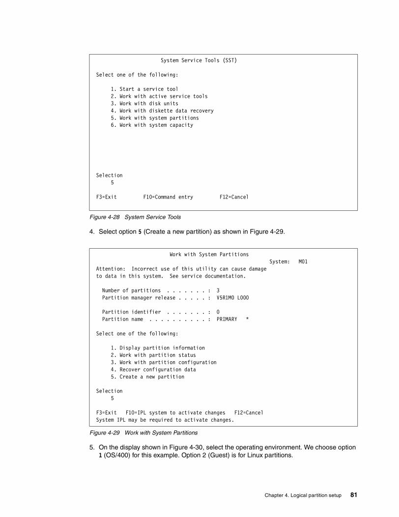
Figure 4-28 System Service Tools
4. Select option 5 (Create a new partition) as shown in Figure 4-29.
Figure 4-29 Work with System Partitions
5. On the display shown in Figure 4-30, select the operating environment. We choose option 1 (OS/400) for this example. Option 2 (Guest) is for Linux partitions.
System Service Tools (SST) Select one of the following: 1. Start a service tool 2. Work with active service tools 3. Work with disk units 4. Work with diskette data recovery 5. Work with system partitions 6. Work with system capacity Selection 5 F3=Exit F10=Command entry F12=Cancel
Work with System Partitions System: M01 Attention: Incorrect use of this utility can cause damage to data in this system. See service documentation. Number of partitions . . . . . . . : 3 Partition manager release . . . . . : V5R1M0 L000 Partition identifier . . . . . . . : 0 Partition name . . . . . . . . . . : PRIMARY * Select one of the following: 1. Display partition information 2. Work with partition status 3. Work with partition configuration 4. Recover configuration data 5. Create a new partition Selection 5 F3=Exit F10=IPL system to activate changes F12=Cancel System IPL may be required to activate changes.
Chapter 4. Logical partition setup 81

Figure 4-30 Select Operating Environment
6. Type in the appropriate information as shown in Figure 4-31 for processors, memory, and interactive. Note that you must press F9 to see the minimum and maximum fields. In this example, we use shared processors.
Figure 4-31 Create New Partition
7. On the screen in Figure 4-32, you select whether this partition will use virtual OptiConnect or specify which virtual LANs will be used by this partition.
Select Operating Environment System: M01 Select one of the following: 1. OS/400 2. Guest Selection 1 F3=Exit F12=Cancel
Create New Partition System: M01 Complete blanks, press Enter. Partition identifier and name . . . . . . . . . 1 AS01B Number of available system processors . . . . : 0 Number of partition processors . . . . . . . . . 4 Minimum / maximum number of processors . . . . . 1 / 4 Use shared processor pool . . . . . . . . . . . 1 1=Yes, 2=No Shared processor pool units . . . . . . . . . 3 . 50 Minimum / maximum processor pool units . . . . 0 . 10 / 4 . 00 Size of available system main storage (MB) . . : 2930 Size of partition main storage (MB) . . . . . . 2930 Minimum / maximum size of main storage (MB) . . 1024 / 4096 Interactive feature available . . . . . . . . : 50 % Partition interactive feature . . . . . . . . . 50 % Minimum / maximum interactive feature . . . . . 0 / 50 % F3=Exit F9=Exclude limits F10=Work with shared processor pool F11=Display partition processing configuration F12=Cancel
82 LPAR Configuration and Management: Working with iSeries Logical Partitions

Figure 4-32 Select Communication Options
8. The screen in Figure 4-33 is shown at the *IOP level, which avoids the clutter of all the IOAs. In this case, the buses are selected as Use bus shared because on this system P0 owns the buses as Own bus shared. Select the desired IOPs as Own dedicated. It is the only option that can be used for IOPs.
Figure 4-33 Add I/O Resources
9. Presuming you selected the correct resources, press Enter to confirm your choices (see Figure 4-34).
Select Communication Options System: M01 Partition identifier . . . . . . . . . . . . . : 1 Partition name . . . . . . . . . . . . . . . . : AS01B Complete blank, type changes, press Enter. 1=Yes 2=No Connect to Virtual OptiConnect . . . . . . . . . 1 -------------------Virtual LAN Identifiers------------------- 0 1 2 3 4 5 6 7 8 9 10 11 12 13 14 15 1 2 1 2 2 2 2 2 2 2 2 2 2 1 1 1 F3=Exit F11=Display communication options F12=Cancel
Add I/O Resources System: M01 Level of detail to display . . . . . . *IOP *ALL, *BUS, *IOP, *IOA, *DEV Partition identifier . . . . . . . . . . . . . : 1 Partition name . . . . . . . . . . . . . . . . : AS01B Type options, press Enter. 1=Own dedicated 2=Own bus shared 3=Use bus shared I/O Resource Serial Part Opt Description Type-Model Number Number 3 System Bus 2 28AA- C8-91006 24L0926 1 Combined Function IOP 2843-001 10-87056 3 System Bus 4 00-0000000 1 Combined Function IOP 671A-001 10-0172004 0000091H4086 1 Storage IOP 2644-001 10-7254022 3 System Bus 5 00-0000000 1 Storage IOP 2624-001 10-5214029 Communications IOP 2810-001 10-7133004 1 Workstation IOP 6050-001 10-6003268 More... F3=Exit F9=Toggle empty pos F10=Display logical address F12=Cancel
Chapter 4. Logical partition setup 83

Figure 4-34 Confirm Add I/O Resources
10.Select the appropriate load source resource IOP as shown in Figure 4-35.
Figure 4-35 Select Load Source Resource
11.Press Enter to confirm load source choice as in Figure 4-36.
Confirm Add I/O Resources System: M01 Press Enter to confirm your choice to add the following I/O resources to this partition. Press F12 to return to change your choice. Partition identifier . . . . . . . . . . . . . : 1 Partition name . . . . . . . . . . . . . . . . : AS01B I/O Resource Serial Part Opt Description Type-Model Number Number 3 System Bus 2 28AA- C8-91006 24L0926 1 Combined Function IOP 2843-001 10-87056 3 System Bus 4 00-0000000 1 Combined Function IOP 671A-001 10-0172004 0000091H4086 1 Storage IOP 2644-001 10-7254022 3 System Bus 5 00-0000000 1 Storage IOP 2624-001 10-5214029 1 Workstation IOP 6050-001 10-6003268 1 Storage IOP 6534-001 10-7074007 0000021H8940 1 Communications IOP 2629-001 10-0286016 More... F10=Display logical address F12=Cancel
Select Load Source Resource System: M01 Level of detail to display . . . . . . *IOP *ALL, *BUS, *IOP, *IOA, *DEV Type option, press Enter. 1=Select IOP I/O Resource Serial Part Opt Description Type-Model Number Number System Bus 2 28AA- C8-91006 24L0926 System Bus 4 00-0000000 1 Combined Function IOP 671A-001 10-0172004 0000091H4086 System Bus 5 00-0000000 System Bus 23 2689- 01-9876543 24L4307 System Bus 24 2689- 18-1085020 21P5840 * Indicates load source. F3=Exit F9=Do not filter resource capability F10=Display logical address F12=Cancel Add I/O resource(s) was successful.
84 LPAR Configuration and Management: Working with iSeries Logical Partitions

Figure 4-36 Confirm Load Source Resource
12.The screen shown in Figure 4-37 allows you to select the console resource. Select the appropriate IOP.
Figure 4-37 Select Console Resource
13.Confirm your console choice by pressing Enter.
Confirm Load Source Resource System: M01 Press Enter to confirm your choice to select the following resource as the load source IOP for the partition. Press F12 to return to change your choice. I/O Resource Serial Part Description Type-Model Number Number Combined Function IOP 671A-001 10-0172004 0000091H4086 F10=Display logical address F12=Cancel
Select Console Resource System: M01 Level of detail to display . . . . . . *IOP *ALL, *BUS, *IOP, *IOA, *DEV Current filter setting . . . . . . . : Twinaxial Type option, press Enter. 1=Select console IOP 2=Select alternate console IOP I/O Resource Serial Part Opt Description Type-Model Number Number System Bus 2 28AA- C8-91006 24L0926 System Bus 4 00-0000000 Combined Function IOP * 671A-001 10-0172004 0000091H4086 System Bus 5 00-0000000 1 Workstation IOP 6050-001 10-6003268 System Bus 23 2689- 01-9876543 24L4307 System Bus 24 2689- 18-1085020 21P5840 < Indicates console IOP. > Indicates alternate console IOP. F3=Exit F9=Change capability filter F10=Display logical address F12=Cancel Load source IOP selection was successful.
Chapter 4. Logical partition setup 85

Figure 4-38 Confirm Console Resource
14.Review all of your selections as shown in Figure 4-39 and press Enter to confirm. Notice that as you have been making and confirming your selections, at the bottom those screens, you see messages such as “Load source IOP selection was successful.”
Figure 4-39 Confirm New Partition
15.This brings you back to the Work with System Partitions display (Figure 4-40), on which you see the message “Partition 1 create was successful.” Select option 3 (Work with partition configuration) to see the list of partitions.
Confirm Console Resource System: M01 Press Enter to confirm your choice to select the following resource as the console IOP for the partition. Press F12 to return to change your choice. I/O Resource Serial Part Description Type-Model Number Number Workstation IOP 6050-001 10-6003268 F10=Display logical address F12=Cancel
Confirm New Partition System: M01 Verify information, press Enter. Partition identifier and name . . . . . . . . : 1 AS01B Number of partition processors . . . . . . . . : 4 Minimum / maximum number of processors . . . . : 1 / 4 Use shared processor pool . . . . . . . . . . : Yes Shared processor pool units . . . . . . . . : 3.50 Minimum / maximum processor pool units . . . : 0.10 / 4.00 Size of partition main storage (MB) . . . . . : 2930 Minimum / maximum size of main storage (MB) . : 1024 / 4096 Partition interactive feature . . . . . . . . : 50 % Minimum / maximum interactive feature . . . . : 0 / 50 % Virtual OptiConnect / Virtual LAN . . . . . . : Yes / Yes I/O Resource Serial Part Description Type-Model Number Number System Bus 2 28AA- C8-91006 24L0926 Combined Function IOP 2843-001 10-87056 More... F3=Exit F10=Display logical address F11=Select alternate IPL resource F12=Cancel Console IOP selection was successful.
86 LPAR Configuration and Management: Working with iSeries Logical Partitions

Figure 4-40 Work with System Partitions
16.In Figure 4-41, note that the newly created partition (AS01B) is marked with the “<“ symbol, which indicates an IPL may be required. Since the creation of a partition requires an IPL, press F11 to work with partition status and IPL the primary (consequently the whole system).
Figure 4-41 Work with Partition Configuration
Work with System Partitions System: M01 Attention: Incorrect use of this utility can cause damage to data in this system. See service documentation. Number of partitions . . . . . . . : 4 Partition manager release . . . . . : V5R1M0 L000 Partition identifier . . . . . . . : 0 Partition name . . . . . . . . . . : PRIMARY * Select one of the following: 1. Display partition information 2. Work with partition status 3. Work with partition configuration 4. Recover configuration data 5. Create a new partition Selection 3 F3=Exit F12=Cancel Partition 1 create was successful.
Work with Partition Configuration System: M01 Type option, press Enter. 1=Change partition name 2=Change partition processing resources 3=Add I/O resources 4=Remove I/O resources 5=Change bus ownership type 6=Select load source resource Partition Option Identifier Name 0 PRIMARY 1 AS01B < 2 AS01C 3 LINUX1 < Indicates partition IPL may be required. F3=Exit F5=Refresh F9=Work with shared processor pool F10=Work with Virtual LAN configuration F11=Work with partition status F12=Cancel F23=More options
Chapter 4. Logical partition setup 87

4.4 Creating a shell partitionThe purpose of creating a shell partition is to provide a partition for future use. Dynamic resource movement allows you to add resources to the shell later without having to IPL the system again since the partition is already created.
The following steps assume that Operations Navigator is already setup on your PC and that you have set up a connection to the system you want to partition.
If this is the first time you are using Operations Navigator to create a logical partition on this system, you first need to add your system to the Systems with Partitions folder using the following steps:
1. In Operations Navigator, click the plus sign [+] to expand Management Central.
2. Right-click Systems with Partitions and select Add System. You must provide an IP address or system name for the system's primary logical partition you want to add.
3. The Service Device Sign-on window prompts you for a Service tools user ID and password. For more information, see 6.10.3, “Service tools security” on page 117.
4. You can provide a description, and click Finish on the Add System window.
If you already added your system to the Systems with Partitions folder and you want to create a new logical partition on your system, follow these steps:
1. In Operations Navigator, click the plus sign [+] to expand Management Central.
2. Click the plus sign [+] to expand Systems with Partitions.
3. Select the physical system where you want to create a new logical partition.
4. The Service Device Sign-on window prompts you for a Service tools user ID and password. For more information, see 6.10.3, “Service tools security” on page 117.
5. Right-click Systems with Partitions and select Configure Partitions. This opens the Configure Logical Partitions window as shown in Figure 4-42.
Figure 4-42 Configure Logical Partitions main window
6. Right-click Physical System and select New Logical Partition. This starts the wizard. Next, a Welcome display appears as shown in Figure 4-43. Note the HELP button located on the bottom right-hand corner. This will be available during the entire process. If you need help on any topic, click this button. If you want specific help, click the small question mark (?) to the right of the Help button and then click the part for which you want help.
ASM03
ASM03: Physical System
88 LPAR Configuration and Management: Working with iSeries Logical Partitions

Figure 4-43 Welcome to the New Logical Partition wizard!
If you click the Partition Requirements button, it shows you the window as shown in Figure 4-44. Click the OK button.
Figure 4-44 New Logical Partition - Partition Requirements window
You now return to the Welcome screen. Since the Create new OS/400 partition for future use option is already selected, and that is the task we want to perform, click Next.
7. The New Logical Partition - Name window appears as shown in Figure 4-45. Fill in the Partition name and select a Partition ID. Click Next.
Chapter 4. Logical partition setup 89

Figure 4-45 New Logical Partition - Name window
8. The New Logical Partition - Memory window appears as shown in Figure 4-46.
Figure 4-46 New Logical Partition - Memory window
Figure 4-46 shows that all the memory is available in Unassigned Hardware. The only resource requirement for a shell partition is a minimum of 64 MB of memory. This is the minimum memory for a shell partition, not to start the partition. You must allocate more memory before you attempt to start this partition.
90 LPAR Configuration and Management: Working with iSeries Logical Partitions

9. Move memory from the Unassigned Hardware to Shell1 as shown in Figure 4-47. Select Unassigned Hardware and type 64 in the Memory to move field. Click the Move button. The Total memory for partition Shell1 box changes to 64. You should also specify min/max for the memory to prevent the need for another IPL when adding other resources to the partition later.
Figure 4-47 Moving memory from Unassigned Hardware to new partition Shell1
10.Click Next.
11.Now you move on to the New Logical Partition Shell1 - Summary display (Figure 4-48).
Figure 4-48 New Logical Partition Summary
Chapter 4. Logical partition setup 91

You have now successfully created a partition for future use. The Summary box describes the partition you just created and shows the minimum requirements you have to add when you want to make that partition active. As in creating any partition, it is necessary for the system to be IPLed. Depending on your situation, you will select:
– Yes, restart the entire system now– No, I will restart the entire system later.
Then click Finish. You will either be driven into an IPL or returned to the Configure Logical Partitions display. You can refresh the view to see the icon for Shell1 as shown in Figure 4-49.
Figure 4-49 Configure Logical Partitions display after completion the creation of Shell1
ASM05
ASM05: Physical System
92 LPAR Configuration and Management: Working with iSeries Logical Partitions

Chapter 5. Migrating logical partitions
Migrating logical partitions is a straightforward task when it is properly planned. This chapter covers the basic planning steps involved when migrating from an existing LPAR environment. The topics in this chapter include:
� “7xx LPAR to 8xx LPAR without a managing partition” on page 94� “7xx LPAR to 8xx LPAR with a managing partition (primary)” on page 96� “Inserting a thin primary on an existing 8xx partitioned system” on page 99
5
© Copyright IBM Corp. 2002 93

5.1 LPAR with migrated systemsThere are numerous scenarios where previously logically partitioned systems will be migrated to new iSeries servers to take advantage of the partial processor capability of V5R1. This section looks at the steps necessary to migrate those systems that have already implemented logical partitioning to a new iSeries with multiple partitions.
This chapter discusses the various ways in which you can migrate from your current AS/400e or iSeries LPAR environment to an 8xx LPAR environment. This falls into three basic categories:
� Category one: Migrating from a system that has already implemented LPAR to an 8xx system that maintains the same partition configuration.
� Category two: Upgrading to an iSeries server where the primary partition is purely a managing partition. This is sometimes referred to as a thin primary.
� Category three: Inserting a thin primary partition (without a system upgrade) into an existing, already partitioned system.
5.2 7xx LPAR to 8xx LPAR without a managing partitionLet’s begin with a high level overview of the process and make some assumptions. One-step migration is the standard upgrade of an LPAR environment. It follows the same theme as a non-LPAR upgrade. This upgrade allows all partitions to take advantage of the new processors and memory, with a relatively simple upgrade process. This type of migration involves the use of a load source pump and LPAR configuration recovery to maintain a similar looking LPAR environment after the migration to 8xx has completed.
AssumptionsWe make the following assumptions:
� This is for an upgrade where the serial number stays the same and not a new system side-by-side style order.
� All partitions in the current 7xx system have V5R1 previously installed if they intend to use partial processors on the 8xx.
� There has been a decision to not have a thin primary partition as a managing partition.
� All LPAR planning and solution assurance reviews have been completed and passed by an IBM Representative or IBM Business Partner that has been trained in LPAR. There are no details or specifics involved in the physical hardware planning or upgrade process itself (in this section) due to the variety of variables possible.
� The target system will have the same number of, or more, processors than the source.
� The target system will have the same number of, or more, MB of main storage than the source.
� The target system will contain all buses and I/O resources used on the source.
� Some tasks in this process will require an LPAR hardware trained IBM SSR to perform.
This section looks at the conventional method of migrating from an existing LPAR environment to an 8xx LPAR environment, maintaining as closely as possible the underlying characteristics that define each partition. The underlying resources of each partition will not be the same as they were before the migration. For example, we may have upgraded from a 12-way to a 24-way system, or main storage may have been increased. These resources need to be allocated to the relevant partitions at the end of the migration. During migration,
94 LPAR Configuration and Management: Working with iSeries Logical Partitions

the source system unit may have been migrated to a migration tower and will be attached to the new 8xx system by a High Speed Link (HSL). The following example helps you to visualize the process for doing this standard LPAR upgrade to the iSeries. Figure 5-1 shows an existing AS/400 Model 730 4-way with three logical partitions being upgraded to an iSeries Model 830 4-way with the same three partitions.
Figure 5-1 Basic 7xx LPAR upgrade to 8xx iSeries: All partitions running
Upgrade tasksThis section discusses the necessary IBM supported tasks to perform the type of upgrade discussed in the previous section. The responsibilities for these tasks are also presented.
1. Ask an LPAR trained IBM Representative or IBM Business Partner to review both the pre-migration and post-migration configurations. This ensures that the target hardware that is proposed will support the partitions as proposed in the LPAR planning sheets.
2. Each source partition must be upgraded to the release supported by target bus 1 hardware. For an 8xx system, this requires V4R5 and PTF levels or V5R1 depending on the hardware used and the function required in the partition. This is a customer responsibility.
3. Perform a full system save of all partitions prior to the upgrade. This is a customer responsibility.
4. Power down all secondary partitions. This can be done after secondary saves are completed by the customer.
5. Define secondary partitions as “sys IPL action” hold and “mode” manual. This ensures that the secondary partitions will not IPL automatically when the primary partition performs numerous IPLs during the migration process. This can be done by the IBM SSR or customer.
6. Power down the primary partition. This should be done by the IBM SSR after the final checklist review.
7. Upgrade the hardware. The IBM SSR will follow their MES upgrade instructions for all hardware changes.
730 4-WAY5073/5058 5073/5058 5073/5058
5073/5058 5073/5058 5073/5058
NEW 830 4-WAY
NEW 5077
Partition A Partition B Partition C
MIGRATION
SPD buses moved to new830 connected to the #5077migration tower
2)Load SourceMigration1)Recover Partition
Configuration
Ship new 5077, move features from CEC to 5077and return CEC
All partitions are recommend to be at V5R1
HSL
Chapter 5. Migrating logical partitions 95

8. Power on the new 8xx system unit.
9. An LPAR configuration error report screen appears. This is because you are IPLing off a new load source disk unit in the new 8xx system unit. There is no LPAR configuration on the load source at this moment in time, but there is LPAR configuration data on the load source of all the secondary partitions. This conflict is what causes the error at this stage.
10.Verify the reporting hardware.
11.Recover and migrate the LPAR configuration (mainly bus number changes). This now migrates the most current LPAR configuration from any of the secondary load source disk units back to the new load source disk unit in the 8xx system unit.
12.Re-IPL the server. This activates those changes as a result of the LPAR configuration recovery.
13.On the IPL, another LPAR configuration error report screen occurs. At this stage, we IPL the new primary partition since the LPAR configuration was previously recovered. However, you still have LPAR configuration data on the old load source disk that was migrated to the migration tower. Therefore, because there are two copies of LPAR configuration data in the primary partition, this error screen is produced.
14.Perform a load source migration. This migrates the old load source data to the new load source disk. This leaves the new LPAR configuration on the new load source disk in tact. SLIC and user data are migrated across. The old load source disk is non-configured at the end of the migration. This leaves one load source disk in the new 8xx system unit and the primary partition.
15.Re-IPL the server. This now IPLs SLIC at the PTF level that was applied prior to the upgrade because SLIC was migrated from the old to the new load source.
16.Allocate the primary I/O resource (DSP01, TAP01, OPT01.......).
17.Reallocate any new system resources into partitions (CPU, memory, interactive CPW).
18.IPL the secondary partitions.
19.Verify secondary partition hardware.
20. Change “sys IPL action” and “mode” to the desired values.
21.Power down the secondary partitions.
22.Set the primary partition to the desired mode (manual/normal/secure...).
23.Change any partition minimum and maximum levels for memory, dedicated or shared processors and interactive CPW as necessary.
24. Re-IPL the primary partition.
5.3 7xx LPAR to 8xx LPAR with a managing partition (primary)This scenario is the most common LPAR upgrade. The ability to run a managing primary partition with only a partial processor allocated is very attractive to most LPAR customers. They do not have to dedicate a full processor to simply manage the secondary partitions. This provides an ideal stable server environment on which they can run their business applications or even have some testing and development going on without fear of affecting their production. This scenario is illustrated in Figure 5-2.
96 LPAR Configuration and Management: Working with iSeries Logical Partitions

Figure 5-2 A three-partition Model 730 upgrading to a Model 830 with a thin primary partition
This section discusses the concepts of migrating from a current 7xx LPAR environment to an iSeries 8xx and implementing a thin managing partition. This process is only discussed at a high conceptual level due to the complexities of each individual situation. The planning process for this type of an upgrade is very extensive and should be done with the help of an LPAR trained software specialist. They will have enough understanding of the many factors that can influence a successful upgrade. If assistance is needed for the LPAR planning process, contact your local IBM Global Services (IGS) representative. IBM Global Services offers LPAR migration services if your staff does not have the skills necessary to complete all of these tasks.
LPAR education (Course S6230 and S6223) is available for Business Partners, IBM Technical Specialists, Support/Services personnel, and customers.
AssumptionsWe make the following assumptions:
� This is for an upgrade where the serial number stays the same and not a new system side-by-side style order.
� All partitions in the current 7xx system have V5R1 previously installed if they intend to use partial processors on the 8xx.
� There has been a decision to create a thin primary partition as a managing partition on the new series 8xx model. All necessary additional hardware to support this has been ordered. This includes a disk controller, two or more disk units for protect disk, a console adapter, and an alternate installation/IPL device.
� All LPAR planning and solution assurance reviews have been completed and passed by an IBM Representative or IBM Business Partner that has been trained in LPAR. No details or specifics involved in the physical hardware planning or upgrade process itself are included in this section due to the variety of variables that are possible.
LPAR upgrade to a thin primary
730 4 WAY5073/5058 5073/5058 5073/5058
5073/5058 5073/5058 5073/5058
NEW 830 4 WAY
NEW 5077
Partition 1 Partition 2 Partition 3
MIGRATION
SPD Buses moved to new830 connected off 5077migration tower
1)Clear PartitionConfiguration
Ship new 5077, move features from System Unit to 5077and return System Unit
BUS 1BUS 2 BUS 3 BUS 4
BUS 1-3
BUS 4
BUS 5 BUS 6 BUS 72) Create thin primary
3) Create new partitions around old hardware
thinprimarypartitionn
Chapter 5. Migrating logical partitions 97

� The target system will have the same number of, or more, MB of main storage than the source.
� Some tasks in this process will require a LPAR hardware trained IBM SSR to perform them.
� The person that will perform the partition configuration is LPAR trained.
Upgrade and migration tasksThis section discusses the necessary upgrade and migration tasks to perform the type of upgrade discussed in the previous section:
1. Ask an LPAR-trained IBM Representative or IBM Business Partner to review both the pre-migration and post-migration configurations. This ensures that the target hardware proposed will support the partitions as proposed in the LPAR planning sheets.
2. Acquire any additional hardware needed to fulfill the new design. The minimum new hardware to support the new thin primary must include a disk controller, two or more disk units for protection, a console adapter, and an alternate installation/IPL device.
3. Each source partition must be upgraded to the release supported by target bus 1 hardware. For an 8xx system, this requires V4R5 and PTF levels and V5R1 depending on the hardware used and function desired in the partition. This is a customer responsibility.
4. Perform a full system save of all partitions prior to the upgrade. This is a customer responsibility.
5. Print out current LPAR configuration and have it available to reconfigure the partitions.
6. Power down all secondary partitions. This can be done after secondary saves are completed by the customer.
7. Define secondary partitions as “system IPL action” hold and “mode” manual. This ensures that the secondary partitions will not IPL automatically when the primary partition performs numerous IPLs during the migration process. This can be done by the IBM SSR or customer.
8. Power down the primary partition. This should be done by the IBM SSR after they have reviewed any last minute checks.
9. The new 8xx system unit must have been ordered with enough new hardware to support the new thin primary as described in step 2. The new 8xx system unit can be powered on ahead of the upgrade weekend to save time, if additional power can be installed. Create your primary partition ahead of the upgrade if you want to save some time. The new 8xx system unit will arrive with only SLIC installed on the load source.
10.Install OS/400 and a current cumulative PTF package on the primary partition.
11.This task creates a thin primary partition. You can use Operations Navigator or the 5250 interface in DST to create the thin primary partition. The basic tasks include changing the desired number of processors from dedicated to shared processors. You can then allocate minimum processor and memory to the primary partition. This is why this managing partition is known as a “thin primary”. The remainder of the system resources will be available for your new partitions to be created after the hardware has been physically connected to the new 8xx system unit through the migration tower.
12.Power down the 8xx system unit to prepare for the actual upgrade.
13.Upgrade the hardware. The IBM SSR will follow their MES upgrade CUI instructions for all hardware changes up to the point of where they would start the load source migration.
14.Power on the new 8xx system unit.
15.An LPAR configuration error report screen appears. This is because you are IPLing off a new load source disk unit in the new 8xx system unit. There is no LPAR configuration on
98 LPAR Configuration and Management: Working with iSeries Logical Partitions

the load source at this moment in time, but there is LPAR configuration data on the load source of all the secondary partitions. This conflict is what causes the error at this stage.
16.Verify that the reporting hardware contains all expected busses and IOPs.
17.Go to the Work with System Partitions screen in DST. Select option 4 (Recover configuration data). On the Recover Configuration data screen, select option 3 (Clear non-configured disk unit configuration data). A report appears that shows a number of load sources equal to the number of partitions on the old stem. There could be additional load sources, if disk mirroring was in effect. Be sure to clear all load sources of LPAR configuration data. This does not erase any user data off of the drives. This removes most of the error messages that appeared during the IPLs.
18.Recreate the partitions around the old hardware using the prefilled in worksheets and the old LPAR configuration as a guide. You can use either the new GUI LPAR configuration wizard or the traditional 5250 twinax screen for this task. Be sure to select the appropriate load source IOP for each partition correctly. If this is done properly, there will be no loss of data, and doing a “B” IPL in the next task should make the partition available for use very quickly.
19.IPL the primary partition to activate the changes after you are satisfied that the secondary partitions have the right minimum and maximum levels of system resources set correctly. This is the main reason that an IPL is needed at this time.
20.IPL the secondary partitions with a “B” mode.
21.Verify the secondary partition hardware.
22.Change “system IPL action” and “mode” to the desired values.
23.Power down the secondary partitions.
24.Set the primary partition to the desired mode (manual/normal/secure...). Re-IPL the primary partition to make all changes take effect.
5.4 Inserting a thin primary on an existing 8xx partitioned system
This section discusses the concepts of inserting a thin managing partition on an existing 8xx partitioned system. This process is only discussed at a high conceptual level due to the complexities of each individual situation. The planning process for this type of change is very extensive and should be done with the help of an LPAR-trained software specialist. They will have enough understanding of the many factors that can influence a successful addition. If assistance is needed for the LPAR planning process, contact your local IBM Global Services (IGS) representative. IBM Global Services offers LPAR migration services if your staff does not have the skills necessary to complete all of these tasks.
LPAR education (Course S6230 and S6223) is available for Business Partners, IBM Technical Specialists, Support/Services personnel, and customers.
AssumptionsWe make the following assumptions:
� This is for a change where the serial number stays the same because there is no upgrade and only additional hardware is ordered.
� All partitions in current 8xx system have V5R1 previously installed if they intend to use partial processors after the change.
� There has been a decision to create a thin primary partition as a managing partition on the existing iSeries 8xx model. All necessary additional hardware to support this has been
Chapter 5. Migrating logical partitions 99

ordered. This includes a disk controller, two or more disk units for protect disk, a console adapter, and an alternate installation/IPL device.
� All LPAR planning and solution assurance reviews have been completed and passed by an IBM Representative or IBM Business Partner that has been trained in LPAR. There are no details or specifics involved in the physical hardware planning or upgrade process itself included in this section due to the variety of variables possible.
� The target system will have the same number of, or more, MB of main storage than the source.
� Some tasks in this process will require an LPAR hardware-trained IBM SSR to perform them.
� The person that will perform the partition configuration must be LPAR trained.
MES and migration tasksThis section discusses the MES and migration tasks to perform the type of upgrade discussed in the previous section:
1. Ask an LPAR trained IBM Representative or IBM Business Partner to review both the pre-change and post-change configurations. This ensures that the target hardware proposed will support the partitions as proposed in the LPAR planning sheets.
2. Acquire any additional hardware needed to fulfill the new design. The minimum new hardware to support the new thin primary must include a disk controller, two or more disk units for protection, a console adapter, and an alternate installation/IPL device. In addition, it is likely that a new expansion tower is needed to house the current frontend of what will become P1 (load source drive/adapter, etc.).
3. The existing source partitions do not require any software upgrade to do this because they will continue to function as the currently do.
4. Perform a full system save of all partitions prior to the upgrade. This is a customer responsibility.
5. Print out current LPAR configuration and have it available to reconfigure the partitions.
6. Power down all secondary partitions. This can be done after secondary saves are completed by the customer.
7. Define secondary partitions as “system IPL action” hold and “mode” manual. This ensures that the secondary partitions will not IPL automatically when the primary partition performs numerous IPLs during the migration process. This can be done by the IBM SSR or customer.
8. Power down the primary partition. This should be done by the IBM SSR after they have reviewed any last minute checks.
9. Install the new hardware ordered and rearrange the existing hardware from P1 per the LPAR planning documents.
10.Power on the system unit and install SLIC.
11.An LPAR configuration error report screen appears. This is because you are IPLing off a new load source disk unit in the 8xx system unit. There is no LPAR configuration on the load source at this moment in time, but there is LPAR configuration data on the load source of all the secondary partitions. This conflict is what causes the error at this stage.
12.Verify the reporting hardware contains all expected busses and IOPs.
13.Go to the Work with System Partitions screen in DST. Select option 4 (Recover configuration data). On the Recover Configuration data screen, choose option 3 (Clear non-configured disk unit configuration data). There will be a report that shows a number of load sources equal to the number of partitions on the old system. There could be
100 LPAR Configuration and Management: Working with iSeries Logical Partitions

additional load sources, if disk mirroring was in effect. Be sure to clear all load sources of LPAR configuration data. This does not erase any user data off of the drives. This removes most of the error messages that appeared during the IPLs.
14.Recreate the partitions around the old hardware using the prefilled in worksheets and the old LPAR configuration as a guide. You can use the new GUI LPAR configuration wizard or the traditional 5250 twinax screen for this task. Be sure to select the appropriate load source IOP for each partition correctly. If this is done properly, there will be no loss of data. Also, doing a “B” IPL in the next task should make the partition available for use very quickly.
15.IPL the primary partition to activate the changes after you are satisfied that the secondary partitions have the right minimum and maximum levels of system resources set correctly. This is the main reason that an IPL is needed at this time.
16.Install OS/400 and PTFs in the new primary partition.
17.IPL the secondary partitions with a “B” mode.
18.Verify the secondary partition hardware.
19.Change “system IPL action” and “mode” to the desired values.
20.Power down the secondary partitions.
21.Set the primary partition to the desired mode (manual/normal/secure...). Re-IPL the primary partition to make all changes effective.
Chapter 5. Migrating logical partitions 101

102 LPAR Configuration and Management: Working with iSeries Logical Partitions

Chapter 6. Operating LPAR environments
This chapter provides information about the requirements of the daily operations of a partitioned system environment. It includes considerations concerning security and save and restore as they pertain to implementation as well as operation. The following topics are covered in this chapter:
� “Choosing a system console” on page 104� “Working with Operations Navigator along with DST/SST” on page 110� “Saving and restoring partitions” on page 113� “System values” on page 114� “IPL process” on page 139� “Licensed key management” on page 145
6
© Copyright IBM Corp. 2002 103

6.1 All about consoles on iSeriesConsoles on the iSeries and AS/400 have always been a highly debated issue. There are some people who feel that because the “green screen” is still available, the iSeries must be old technology. There are others who want the PC-based GUI, although others are convinced that with this method, they may be introducing a new single point of failure into their system. Twinax console is a great solution because there are few problems that can arise with this direct attached device.
We recommend you use the twinax console for your primary or have it on a shared bus, so you can move it around. Use the LAN console for primary and secondary partitions that your technical people access. These are some people who need to do day-to-day advanced operations from their workstation, not in the machine room.
6.1.1 iSeries console options available at V5R1On the iSeries server at V5R1, there are three distinct modes to connect a system console:
� Twinaxial PCI:
– Green screen commonly called a “Dumb Terminal”– PC with 5250 emulation adapter
� Operations Console: A console with a direct PC connection
� Operations Console LAN attached: A console connect via the local area network
The Client Access sync console is not supported on a system running V5R1 of OS/400.
6.1.2 iSeries console options available at V4R5At V4R5, there are three ways to connect a system console:
� Twinaxial PCI/SPD attachment to:
– Green screen commonly called a “Dumb Terminal” or “ASCII Terminal”– PC with 5250 Emulation adapter
� Communications console
– Client Access to a PC– Client Express to a PC
� Operations Console
– Client Express to a PC
6.2 Choosing a system consoleThe system unit control panel controls the entire system, including the primary partition. Control panel functions for secondary partitions are provided by a new service function under DST/SST. Console functions are provided through either a twinaxial workstation or a PC using the Operations Console function.
The following requirements pertain to control panel and console functions:
� You must specify the console IOP during partition setup.
� You may specify the same IOP for both the console and the alternate console.
104 LPAR Configuration and Management: Working with iSeries Logical Partitions

� If you use Operations Console, the same IOP must be specified for both the electronic customer support line and the main console for the partition.
� For hardware service, a functional console for the partition being serviced must be in the same room as, and within 20 feet of, the system unit.
� The following consoles are not supported for logical partitions:
– Communications Console Attachment – ASCII Workstation Attachment – Apple Talk ™ Device Attachment
� A secondary partition searches for an active workstation at the lowest address on the IOP that is designated as a console or alternate console.
� IBM does not recommend that you have twinaxial workstations and Operations Console on the same IOP, unless you want a twinaxial workstation to be the main console for the partition. If Operations Console is set to be the main console on an IOP with twinaxial workstations, some problems may develop in the following situations:
– If you restart the system in manual mode and the system searches for the console at DST.
– If the twinaxial controller has a workstation that is powered on and assigned to port 0, address 0.
If either of these situations happen, Operations Console will not connect, and a twinaxial workstation will be assigned to be the main display.
6.3 Console recommendationsTo interact with your new server, you need a system console. You have three choices for your system console. Choose one of these console options, and make sure the necessary equipment is ready when your system arrives.
� Operations Console (recommended)
Operations Console allows you to use a familiar Windows-style graphical interface through your own personal computer setup as a system console.
– Easy to use for a person who has a PC background – Available on V4R3 or later– Support local and remote connection– Need to plan the console upgrade before system upgrade
� LAN console (recommended)
Allows you to use a PC through a LAN connection to set up your system console.
– Available on V5R1– Supports a LAN connection– Good online help text– Not supported by SPD– Need to plan the console upgrade before system upgrade
� Twinaxial console
A twinaxial console allows you to use a basic command line interface and does not require you to use a personal computer as a system console. It is:
– Reliable– Easy-to-configure – Move to other partition with the attached IOP
Chapter 6. Operating LPAR environments 105

– Support to any version and release– Good performance
6.4 Console requirementsTo interact with your system, you need to set up a system console. There are three types of consoles as we explained in the previous section. This section explains the requirements of each type. Figure 6-1 shows you three types of consoles.
Figure 6-1 System console options
6.4.1 Operations Console Operations Console allows you to use a familiar Windows-style graphical interface through a personal computer that is set up as your system console. In addition, you can use the EZ-Setup wizard to help you configure your Operations Console. The EZ-Setup wizard helps you to install Operations Navigator. It helps you set the system name, date, time, and some basic security values, as well as perform some other tasks. The PC-setup requirements for running Operations Console as a stand-alone local controlling system (LCS) are the same as the requirements needed to run the EZ-Setup wizard.
Operations Console is supported on (Windows 98 or later is recommended):
� Windows 95 � Windows 98 � Windows NT Workstation 4.0 or later � Windows ME� Windows 2000 Professional
iSeries
LAN
Twinax cable Multiple connection
options
Twinaxle Console (Twinax Terminal orPC with 5250 Emulation)
Operations Console with Client Access Express package downloaded from iSeries
106 LPAR Configuration and Management: Working with iSeries Logical Partitions

Operations Console allows you to use your PC to access and control (remotely or locally) the AS/400 console and AS/400e or iSeries control panel. To access the AS/400e or iSeries system console and control panel, a console PC or local controlling system must be directly connected to the AS/400e or iSeries server using a directly attached cable, LAN, or a dial-up connection. If directly attached, the LCS can be configured to access the AS/400e or iSeries console, the AS/400e or iSeries control panel, or both. If using a dial-up connection, only the AS/400e or iSeries console can be accessed.
Once a directly attached LCS connection to the AS/400e or iSeries server is configured, connections from remote PCs or remote controlling systems (RCS) can be established via the LCS.
Here are some notes and considerations for setting up an Operations Console:
� A stand-alone LCS does not allow remote PCs (RCSs) to connect to it.
� An LCS with dial-in support allows remote PCs (RCSs) to connect to it.
� An RCS allows your PC to dial in to an LCS to have access to your server.
� If you are configuring a dial-up LCS (a remote PC that dials into the system to become the console), you need to satisfy the same requirements as an RCS.
� If you are configuring a PC as both an LCS and an RCS, you need to satisfy the hardware requirements for both configurations.
� If your PC has power management capabilities, turn it off. This PC may reset the communications port when power management is invoked, which would terminate any connections already established. Certain types of power management on the PC and in the operating system may cause a system reference code (SRC) to appear in the system control panel or remote control panel. This SRC data should clear when PC activity resumes.
� If you are using either COM3 or COM4, be sure that the addresses and the interrupt request settings do not conflict with other hardware resources. You cannot share IRQ settings for Operations Console devices.
� If you are connecting the remote control panel cable to Models 270, 820, 830, or 840, you need an available parallel port instead of a COM port. The parallel port must be configured to use enhanced parallel port (EPP) support, which may require the PC's basic input/output system (BIOS) to change. Check with your PC manufacturer for any assistance, if needed. Due to the way EPP support is being implemented to support the remote control panel, there may be PCs that will not support the use of this function.
If you are configuring a stand-alone LCS, use one of the following the operating systems:
� Windows 95 (with Dial-Up Networking support)� Windows 98 (with Dial-Up Networking support) **Recommended**� Windows NT Workstation 4.0 or later, with Remote Access Service installed. Windows NT
Workstation 4.0 requires Service Pack 3 (at a minimum) or later **Recommended** � Windows 2000 Professional **Recommended** � Windows ME **Recommended**
If your LCS will support an RCS, the operating system must be either Windows NT Workstation 4.0 (or later) or Windows 2000 Professional. For Windows NT Workstation 4.0 or later, Remote Access Services must be installed. Windows NT also requires Service Pack 3 (at a minimum) or later.
The Client Access Express versions, at the LCS and RCS, must be at the same level for proper operation of Operations Console.
Chapter 6. Operating LPAR environments 107

Operations Console is a selectively installable Client Access Express component. You can select it for installation using a custom installation when Client Access Express is installed on your PC. Or, you can add it after Client Access Express is installed using Selective Setup.
Operations Console (Figure 6-2) allows you to use a PC with a supported version of Windows to become a local or remote console to your iSeries server. This eliminates the need for a twinaxial connection. It also allows a system administrator to watch the system from another location. Each iSeries partition must have a console attached to it.
Figure 6-2 Operations Console
6.4.2 LAN consoleOperations Console has been enhanced at OS/400 version V5R1 to enable connections or console activities across a LAN, besides enabling directly cabled and dial-in (modem) connections. A single PC can have multiple connections to multiple iSeries servers and can be the console for multiple iSeries servers. Refer to Chapter 7, “LAN console” on page 147.
On a system without logical partitions, you can use the control panel to perform many tasks. However, for systems with logical partitions, secondary partitions do not have physical control panels. To control your secondary partitions, you can use the remote control panel. After connecting the LAN console, you can access the LAN console Sign On screen (DSP05 which is under QCTL subsystem as shown in Figure 6-3) and the Remote Control Panel as shown in Figure 6-4.
Notes:
� For a detailed explanation of how to use Operations Console and the benefits of using it in a network, see Operations Console Setup, SC41-5508.
� The iSeries Operations Console Update, SK3Y-4114, CD-ROM is required to set up Operations Console with LAN connectivity.
108 LPAR Configuration and Management: Working with iSeries Logical Partitions

Figure 6-3 LAN console Sign On screen
Figure 6-4 Remote Control Panel
6.4.3 Twinaxial consoleA twinaxial console is a traditional AS/400 console. It allows you to use a basic command line interface and does not require you to use a personal computer as a system console. A twinaxial console requires:
� Console monitor and keyboard� Twinaxial console cable (supplied by the customer)
Chapter 6. Operating LPAR environments 109

6.5 Working with Operations Navigator along with DST/SSTWhen you create one or more logical partitions on the iSeries server, you essentially create partitions that are independent of each other. Each logical partition has its own independent configuration such as processor, memory, input/output (I/O) devices, Licensed Internal Code, operating system (OS/400), and optional software applications.
6.5.1 Graphical partition management A key focus item for OS/400 V5R1 was to dramatically simplify the basic day-to-day operational tasks by providing a secured graphical user interface (GUI) through Operations Navigator. OS/400 logical partitioning management tasks, such as creating and deleting new LPARs, dynamic resource movement, and providing a secured access to these tasks based on user profiles, are all part of the new navigation paths. The graphical interface also allows customers to schedule resource movement by specifying a date and time, or using Application Program Interfaces (APIs) to automate resource movement based on application events.
6.5.2 Operations Navigator (GUI) versus DST/SST functionsYou can use either the GUI or green-screen method to implement and manage logical partitions. Generally, Operations Navigator is easy to use for those who are not quite familiar with OS/400 operating system commands.
DST and SST are for iSeries and AS/400 experts to implement and manage LPAR efficiently and check balance. There are some logical partitions functions that still require you to use DST and SST. Logical partition recovery actions and printing system configurations tasks are DST and SST functions only. However, since SST is easier to access than DST, we recommend that you use SST whenever possible to access these tasks.
To use SST or DST, go to 6.10, “Security” on page 116. Table 6-1 describes the capabilities that are available to logical partitions using Operations Navigator or DST and SST.
Table 6-1 Capabilities of logical partitions
Function Operations Navigator DST and SST
Accepting a disk unit as load source for a logical partition
X
Changing a bus ownership type X X
Changing a default electronic customer support resource
X X
Changing a partition name X X
Changing communication options X X
Changing I/O configuration of primary and secondary partitions
X X
Changing operating mode for a logical partition X X
Changing the alternate restart device X X
Changing the restart (or IPL) source for a logical partition
X X
Clearing non-reporting resources on logical partitions X
110 LPAR Configuration and Management: Working with iSeries Logical Partitions

Clearing partition configuration data for logical partitions
X
Clearing partition configuration from non-configured disk units
X
Creating a new OS/400 logical partition X X
Copying partition configuration data between IPL sources
X
Deleting a logical partition X X
Displaying available hardware resources X X
Displaying system resources X X
Displaying the communication options of a logical partition
X X
Displaying the console for a partition X X
Displaying the logical partition OS/400 release level X X
Displaying the remote control panel for a logical partition
X X
Displaying the system reference code history for a primary partition.
X
Displaying the system reference code history for secondary partitions
X X
Enabling High Speed Link (HSL) OptiConnect X X
Enabling virtual LAN communication X X
Enabling Virtual OptiConnect communication X X
Finding a logical address for a resource X X
Moving a dedicated processor X X
Moving a dedicated processor to the shared processor pool
X X
Moving an I/O processor X X
Moving interactive performance, memory, or shared processing power
X X
Performing main storage dumps on servers with logical partitions
X X
Preventing a secondary logical partition from restarting during a system restart
X X
Printing system configuration for logical partitions X
Recovering logical partition configuration data X
Resetting a disk unit I/O processor with logical partitions X
Restarting a secondary logical partition during a system restart
X X
Function Operations Navigator DST and SST
Chapter 6. Operating LPAR environments 111

6.5.3 Security considerationsUsers who want to access logical partition information in Operations Navigator, Dedicated Service Tools (DST), and System Service Tools (SST) must have either operations or administration authority to the logical partition function. In addition, users who want to use the Operations Console remote panel for secondary partitions from their PC must have remote panel authorization.
Use care in administering the appropriate service tool authority for partition control.
6.6 Printing system configuration for logical partitionsPrinting system configuration for logical partitions is only possible from a Service tools screen. The GUI does not support this printing function.
We strongly recommend that you print the system configuration for all of your I/O resources that are allocated to all of the logical partitions, once your setup is complete. Logical partition configuration information is not saved during the save process. Therefore, a printout will be required to allocate appropriate resources if you have to recover your system in a disaster recovery scenario.
You also need to print the system configuration report for all logical partitions should you need to perform an Miscellaneous Equipment Specification (MES) also known as a “hardware upgrade” to your system with logical partitions. This information will assist your IBM Business Partner or IBM Marketing Representative to understand how your system I/O resources are assigned to the logical partitions.
Follow these steps to print the system configuration:
1. From the primary partition start SST or DST.
2. The Service Device Sign-on window prompts you to enter a Service tools user and password (for more information, refer to 6.10, “Security” on page 116).
3. From SST, select option 5 (Work with system partitions); from DST, select option 11 (Work with system partitions) and press Enter.
4. Select option 1 (Display partition information).
5. Select option 5 (Display system I/O resources).
6. At the Level of detail to display field, type *ALL to set the level of detail to ALL.
Restarting a system with logical partitions X X
Updating partition configuration data on all logical partitions
X
Using remote service with logical partitions X X
Viewing the status of a logical partition X X
Function Operations Navigator DST and SST
Attention: Printing a rack configuration listing through Hardware Service Manager within SST only provides you with a configuration listing of the resources that are allocated to that specific partition. This report does not provide details for the entire system. For this reason, you should complete the following steps, using the primary partition.
112 LPAR Configuration and Management: Working with iSeries Logical Partitions

7. Press F6 to print the system I/O configuration.
8. Select option 1 and press Enter to print to a spooled file.
9. Press F12 to return to the Display Partition Information display.
10.Select option 2 (Display partition processing configuration).
11.Press F6 to print the processing configuration.
12.Press F12 to return to Display Partition Information display.
13.Select option 7 (Display communications options).
14.Press F6 to print communication configuration.
15.Press Enter to print to a spooled file.
16.Return to an OS/400 command line and print these three spooled files.
6.7 Resource managementWith the major enhancements delivered with the V5R1 system, partitioning is now enabled with Dynamic Resource Movement or Management (DRM). This capability allows system resources to managed and moved between partitions without the requiring an IPL to the system. This assumes that the minimum and maximum values in partitions being affected have values set to include the desired range of resource movement being attempted:
� Processors� Memory� Interactive feature capacity� Bus ownership� IOPs
With the delivery of DRM, this significant functional enhancement is covered in greater detail in 8.1, “Dynamic resource management” on page 178. The section also provides detailed examples of resource movement.
6.8 Saving and restoring partitionsPartitioning support has not materially changed the requirements for save and restore in a partitioned system environment. With OS/400 V5R1, the need and importance of a sound system management save and restore strategy does not change. Customer environments new to partitioning will find this an opportunity to review their company/corporate availability and save and restore strategy.
Since there is no way to perform a single save or restore for an entire physical system, each partition needs to be treated as a separate independent systems with its own specific requirements based on the workload hosted in that partition. However, it is possible to perform multiple saves or restores concurrently in different partitions, assuming each has its own save and restore device. The process of saving or restoring logical partitions is the same as saving or restoring a system without logical partitioning.
6.8.1 Saving the logical partition configurationYou cannot save the configuration data for logical partitions to a removable media device. The system automatically maintains the configuration data for all logical partitions created on a physical system on the load source disk of each partition.
Chapter 6. Operating LPAR environments 113

When the system is IPLed, it validates the configuration available on the load source disk of the primary partition. If this is not available, it searches the other load source disks and prompts you to select the configuration that should be used.
On a scratch installation of the primary partition, the partition configuration can be recovered from the configuration records stored on the secondary partitions load source drive.
Saving data from logical partitionsSave commands work exactly the same way in a partitioned environment as in a non-partitioned environment. All save operations operate on logical partitions as if they were separate systems. Customers can use exactly the same strategy they are currently using, but on a partition-by-partition basis.
Restoring data to logical partitionsRestore commands work exactly the same way in a partitioned environment as in a non-partitioned environment. All restore operations operate on the logical partitions as if they were separate systems. Customers can use exactly the same restore strategy they are currently using, but on a partition-by-partition basis.
The benefits of a save and restore implementationThe current implementation, in which the partition configuration information is not save to the save media with the save commands, allows the save to be used (restored) to another system regardless of whether it has partitions. This can be a disaster recovery machine that would have a completely different configuration and serial number than the save from system. This fact alone makes it an “intelligent implementation”. Combined with the use of a system serial number to determine whether the restore is to the same system, this is a very flexible save and restore implementation.
6.9 System valuesEvery partition operates independently of the others. Most system values are unique to that partition. However, there are some system values that can only be changed from the primary partition. The value to which they are set influences how the secondary partitions will behave in certain circumstances.
6.9.1 QPRCMLTTSK: Processor multi-taskingThe QPRCMLTTSK system value allows you to turn on and turn off the processor multi-tasking capability. If enabled, more than one set of task data will reside in each CPU. Some workloads may experience increased performance due to caching implications. This system value setting affects all processors in all partitions.
This is only applicable if you have an IStar processor.
6.9.2 QPWRRSTIPL: Automatic IPL after power restoredThe QPWRRSTIPL value specifies whether the system should automatically IPL when utility power is restored after a power failure. It only affects the primary partition. Whether a secondary partition is IPLed at the same time as the primary partition depends on the secondary partition's configuration value for System IPL Action.
114 LPAR Configuration and Management: Working with iSeries Logical Partitions
If the secondary partition System IPL Action is set to IPL, the partition automatically performs an IPL when the primary partition is IPLed. This is set from the Work with Partition Status display on the primary partition.
6.9.3 QRMTIPL: Remote power on and IPLThe QRMTIPL value specifies whether remote power on and IPL can be started over a telephone line. It only affects the primary partition. Whether a secondary partition is IPLed at the same time as the primary partition depends on the secondary partition's configuration value for System IPL Action.
If the secondary partition System IPL Action is set to IPL, the partition automatically performs an IPL when the primary partition is IPLed.
6.9.4 QUPSDLYTIM: Uninterruptible Power Supply delay timeThe QUPSDLYTIM value specifies the amount of time that elapses before the system automatically powers down following a power failure. When a change in power activates the Uninterruptible Power Supply (UPS), messages are sent to the UPS message queue (the system value QUPSMSGQ). This system value is only meaningful if your system has a battery power unit or has an uninterruptible power supply.
6.9.5 QUTCOFFSET: Coordinated Universal Time offsetThe QUTCOFFSET value is used to specify the difference in hours and minutes between UTC, also known as “Greenwich Mean Time” and the current system time.
This value enables the iSeries to differentiate between differing time zones when, for example, you have partitions operating in different countries (or regions) and time zones.
6.9.6 Other related system values and commandsThe system values and commands are not enforced by the operating system. However, their values can impact operating partitions.
� QAUDENDACN: Auditing end action
This value contains the action that should be taken by the system when audit records cannot be sent to the auditing journal because of errors that occur when the journal entry is sent. If this is set to *PWRDWNSYS, the system ends, should the attempt to send the audit data to the security audit journal fail. It ends with a B900 3D10 system reference code.
If this system value is set to *PWRDWNSYS in the primary partition, then this would affect all secondary partitions if a problem is encountered.
� QCMNARB: Communication arbiters
This value contains the number of communication arbiter system jobs that are available to process work for controllers and devices. If set to *CALC (the shipped value), the operating system calculates the number of communication arbiter system jobs to be equal to the number of processors on the system.
On a partitioned system, the number of jobs started are equal to the number of processors on the physical system, not the number assigned to that partition. We recommend that you set this system value manually.
Chapter 6. Operating LPAR environments 115

� QIPLDATTIM: Date and time to automatically IPL
This values specifies a date and time when an automatic IPL should occur. This system value can be set independently in each partition. If the primary partition is powered down at the time when an automatic IPL should occur in a secondary partition, the IPL will not occur. When the primary partition performs an IPL, the secondary partition is IPLed if its IPL date and time are past due. The secondary partition performs an IPL even if it was configured with a System IPL Action of Hold.
The power on and off schedule that can be set from the POWER menu also uses the system value QIPLDATTIM. This function works the same way as described in the previous paragraph.
� QMODEL: System model number
This is the number or letter used to identify the model of the system. You cannot change QMODEL, but the four-character value can be displayed or retrieved in user-written programs. The system model number is the same in each partition on a system.
� QPRCFEAT: Processor feature
This is the processor feature code level of the system. You cannot change QPRCFEAT, but the four-character value can be displayed or retrieved in user-written programs. The processor feature system value is the same in each partition on a system.
� QSRLNBR: System serial number
This value cannot be changed. It is retrieved from the data fields by the system when installing the OS/400 licensed program. You can display QSRLNBR, or you can retrieve this value in user-written programs. The system serial number is the same in each partition on a system.
� CHGIPLA command
The Change IPL Attributes (CHGIPLA) command allows you to change the settings of attributes that are used during the IPL. The hardware diagnostics (HDWDIAG) attribute on this command specifies whether certain hardware diagnostics should be performed during the IPL. The list of diagnostics is pre-determined by the system and cannot be modified by the user.
Hardware diagnostics can only occur when the primary partition is IPLed. This attribute cannot be changed from a secondary partition. Attempting to change this attribute in a secondary partition will result in message CPF18B4 being issued.
6.10 SecurityThis section discusses the security within LPAR and the changes that are related to V5R1. This section does not give you an overall view of security at the OS/400 level, but deals with the very specific issues of security within an LPAR environment.
6.10.1 Security considerationsIt is possible to have different OS/400 security levels (QSECURITY) in each partition and a different security policy implemented by the customer for each partition. One partition may have security down to the object level, but another partition may have all objects secured by group profiles.
A user profile is required for each partition on a physical machine. System supplied user profiles exist on each partition after the operating system is installed. However, there is no dependency between partitions for these profiles.
116 LPAR Configuration and Management: Working with iSeries Logical Partitions

6.10.2 Security changes in V5R1With V5R1, there are significant changes to the security setup, particularly within DST/SST. You can now use profiles other than the shipped ones and define exactly what these profiles can and cannot do.
With V5R1, you must have a password for the following functions:
� D mode IPL� Manual IPL� Option 21 from the control panel� Running SST from the command line� All Operations Navigator LPAR functions
6.10.3 Service tools securityThe standard default profiles are still shipped with the iSeries server. They are QSECOFR, QSRV, 11111111, and 22222222. The profiles for these are shipped with differing password settings and rules and different authority levels.
The QSECOFR and QSRV passwords are required to be in uppercase. These two profiles and the 22222222 profile are all set to expire at first signon. The authority levels of the SST shipped profiles are different from each other as detailed in the following section.
6.10.4 Authority levels for Service tools profilesTable 6-2 shows the breakdown of authority within Service tools for the shipped profiles.
Table 6-2 Privileges for shipped Service tools profiles
Privilege QSECOFR 22222222 11111111 Default QSRV
Disk units - operations 3 3 3
Disk units - administration 3 3 3
System partitions - operations 3 3 3
System partitions - administration 3 3 3
Partition remote panel key 3 3 3 3
Operator panel functions 3 3 3 3
Operating system IPL 3 3 3 3
Install 3 3 3
Performance data collector 3 3 3 3 3
Hardware service manager 3 3
Display/Alter/Dump 3 3
Main storage dump 3 3 3 3
Product Activity Log 3 3 3
Licensed Internal Code log 3 3
Licensed Internal Code fixes 3 3 3 3 3
Trace privilege 3 3 3 3
Chapter 6. Operating LPAR environments 117

6.10.5 System partitions operator and administratorThere is now the ability to easily separate the service functions for the operations staff and the technical support staff. This is done by creating different profiles at the DST level and clearly specifying different access for both functions.
The separation of authorities between the two profiles can be identified as follows:
� LPAR operator: Can move hardware resources and move resources within the minimum and max levels. This profile cannot create or delete partitions or instigate any LPAR recovery processes.
� LPAR administrator: Can create and delete partitions, increase Min/Max LPAR levels, move resources, and recover configurations.
Table 6-3 outlines the differences.
Table 6-3 Difference between LPAR operations and LPAR administration
Dedicated Service Tools (DST) environment
3 3 3 3
Remote service support 3 3 3
Service tool security 3
Service tool save and restore 3
Debug 3 3
Systems capacity - operations ? ? ?
Systems capacity - administration ? ? ?
Privilege QSECOFR 22222222 11111111 Default QSRV
Function LPAR operator
LPAR administrator
Accepting a disk unit as load source for a logical partition 3
Changing a bus ownership type 3
Changing a default electronic customer support resource 3 3
Changing a partition name 3 3
Changing communication options 3 3
Changing I/O configuration of primary and secondary partitions 3 3
Changing operating mode for a logical partition 3
Changing the alternate restart device 3 3
Changing the restart (or IPL) source for a logical partition 3
Clearing non-reporting resources on logical partitions 3
Clearing partition configuration data for logical partitions 3
Clearing partition configuration from non-configured disk units 3
Copying partition configuration data between IPL sources 3
Creating a new OS/400 logical partition 3
118 LPAR Configuration and Management: Working with iSeries Logical Partitions

6.10.6 Creating Service tools profilesAs we discussed already, Service tool profiles are used to allow access to DST/SST for operations and technical staff without having to continually use QSECOFR. This section guides you through the steps to follow for setting up service tool profiles within DST. It also explains how to set the correct authority to allow the user to perform the tasks required.
As stated above, you have the option to clearly separate operations and administration profiles. This is done at the privilege level once the profiles are set up within DST. This process is explained in detailed over the next few pages.
Deleting a logical partition 3
Displaying available hardware resources 3 3
Displaying the communication options of a logical partition 3 3
Displaying the console for a partition 3 3
Displaying the logical partition OS/400 release level 3 3
Displaying the remote control panel for a logical partition 3 3
Displaying the system reference code for a partition 3 3
Displaying system resources 3 3
Enabling virtual LAN communication 3 3
Finding a logical address for a resource 3 3
Moving a dedicated processor 3 3
Moving a dedicated processor to the shared processor pool 3 3
Moving an I/O processor with resources in use 3
Moving an I/O processor with resources not in use 3 3
Moving interactive performance, memory or shared processing power
3 3
Performing main storage dumps on servers with logical partitions 3
Preventing a secondary logical partition from restarting during a system restart
3
Printing system configuration for logical partitions 3 3
Recovering logical partition configuration data 3
Resetting a disk unit I/O processor with logical partitions 3
Restarting a secondary logical partition during a system restart 3
Restarting a system with logical partitions 3
Updating partition configuration data on all logical partitions 3
Using remote service with logical partitions 3
Viewing the status of a logical partition 3 3
Function LPAR operator
LPAR administrator
Chapter 6. Operating LPAR environments 119

You can go into DST in one of two ways. You can either IPL the iSeries up to the DST level and then choose the option to enter DST. Or you can select option 21 from the control panel. If you do this, you see a screen like the one in Figure 6-5. At this point, you must sign on to DST using a valid password and profile.
Figure 6-5 Initial DST screen
Figure 6-6 shows the main screen you see when you first enter DST. On this menu, you must select option 5.
Note: If you are entering into DST for the first time, keep in mind that the DST QSECOFR password is case-sensitive and the default is shipped as uppercase only. Therefore, you need to enter QSECOFR with password QSECOFR (in capital letters).
Dedicated Service Tools (DST) Sign On System: M01 Type choices, press Enter. Service tools user . . . . . . . . . . . Service tools password . . . . . . . . . F3=Exit F5=Change password F12=Cancel
120 LPAR Configuration and Management: Working with iSeries Logical Partitions

Figure 6-6 Use Dedicated Service Tools menu after signing on to DST
You are now at the Work with DST Environment menu as shown in Figure 6-7. You must select option 3 (Service tools user profiles).
Figure 6-7 Work with DST Environment menu
Use Dedicated Service Tools (DST) System: M01 Select one of the following: 1. Perform an IPL 2. Install the operating system 3. Work with Licensed Internal Code 4. Work with disk units 5. Work with DST environment 6. Select DST console mode 7. Start a service tool 8. Perform automatic installation of the operating system 10. Work with remote service support 11. Work with system partitions Selection F3=Exit F12=Cancel
Work with DST Environment System: M01 Select one of the following: 1. Active service tools 2. System devices 3. Service tools user profiles 4. System values 5. Service tools device profiles 6. Service tools security data Selection F3=Exit F12=Cancel
Chapter 6. Operating LPAR environments 121
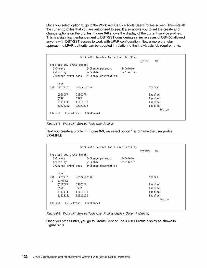
Once you select option 3, go to the Work with Service Tools User Profiles screen. This lists all the current profiles that you are authorized to see. It also allows you to set the create and change options on the profiles. Figure 6-8 shows the display of the current service profiles. This is a significant enhancement to DST/SST considering earlier releases of OS/400 allowed anyone with DST/SST access to work with LPAR configuration. Now a more granular approach to LPAR authority can be adopted in relation to the individuals job requirements.
Figure 6-8 Work with Service Tools User Profiles
Next you create a profile. In Figure 6-9, we select option 1 and name the user profile EXAMPLE.
Figure 6-9 Work with Service Tools User Profiles display: Option 1 (Create)
Once you press Enter, you go to Create Service Tools User Profile display as shown in Figure 6-10.
Work with Service Tools User Profiles System: M01 Type option, press Enter. 1=Create 2=Change password 3=Delete 4=Display 5=Enable 6=Disable 7=Change privileges 8=Change description User Opt Profile Description Status QSECOFR QSECOFR Enabled QSRV QSRV Enabled 11111111 11111111 Enabled 22222222 22222222 Enabled Bottom F3=Exit F5=Refresh F12=Cancel
Work with Service Tools User Profiles System: M01 Type option, press Enter. 1=Create 2=Change password 3=Delete 4=Display 5=Enable 6=Disable 7=Change privileges 8=Change description User Opt Profile Description Status 1 EXAMPLE QSECOFR QSECOFR Enabled QSRV QSRV Enabled 11111111 11111111 Enabled 22222222 22222222 Enabled Bottom F3=Exit F5=Refresh F12=Cancel
122 LPAR Configuration and Management: Working with iSeries Logical Partitions

Figure 6-10 Create Service Tools User Profile screen
The password can be up to 128 characters in length and is case sensitive. The Allow profile access before the storage management recovery option allows the technical support team to be signed on while this is part of the IPL is running. This can also be used to prevent early access by the operations staff. The Set password to expire option forces the Service tools user to change the password at first use.
Figure 6-11 shows that the newly created Service tools user profile has a status of enabled.
Figure 6-11 Work with Service Tools User Profile with the EXAMPLE user
If you select option 4, you can display the details for that selected profile. Figure 6-12 shows the available details for our newly created profile.
Create Service Tools User Profile System: M01 Service tools user profile name . . . . . : EXAMPLE Type choices, press Enter Password . . . . . . . . . . . . . . . . Allow profile access before storage management recovery . . . . . . . 1=Yes, 2=No Set password to expire . . . . . . . . . 1=Yes, 2=No Description . . . . . . . . . . . . . . . F3=Exit F5=Change privilege F12=Cancel
Work with Service Tools User Profiles System: M01 Type option, press Enter. 1=Create 2=Change password 3=Delete 4=Display 5=Enable 6=Disable 7=Change privileges 8=Change description User Opt Profile Description Status EXAMPLE EXAMPLE PROFILE Enabled QSECOFR QSECOFR Enabled QSRV QSRV Enabled 11111111 11111111 Enabled 22222222 22222222 Enabled Bottom F3=Exit F5=Refresh F12=Cancel
Chapter 6. Operating LPAR environments 123

Figure 6-12 Display Service Tools User Profile screen
There a several ways to change the privileges for a profile. We pressed F5 on the screen in Figure 6-12. This takes you to the Change Service Tools User Privileges screen as shown in Figure 6-13. The following five screens show you all the default privileges. These are the same as those listed in Table 6-2 on page 117.
Figure 6-13 Change Service Tools User Privileges (first screen)
Display Service Tools User Profile System: M01 Service tools user profile name . . . . . : EXAMPLE Previous sign-on . . . . . . . . . . . . : 04/10/01 15:56:44 Sign-on attempts not valid . . . . . . . : 0 Status . . . . . . . . . . . . . . . . . : Enabled Date password last changed . . . . . . . : 04/10/01 Allow profile access before storage management recovery . . . . . . . : Yes Date password expires . . . . . . . . . . : 10/07/01 Set password to expired . . . . . . . . . : No Description . . . . . . . . . . . . . . . : EXAMPLE PROFILE F3=Exit F5=Display privilege F12=Cancel
Change Service Tools User Privileges System: M01 Service tools user profile name . . . . . . : EXAMPLE Type option, press Enter. 1=Revoke 2=Grant Option Functions Status None Revoked Disk units - operations Revoked Disk units - administration Revoked System partitions - operations Revoked System partitions - administration Revoked Partition remote panel key XXXXXXXX 000 Revoked Partition remote panel key XXXXXXXX 001 Revoked Partition remote panel key XXXXXXXX 002 Revoked Partition remote panel key XXXXXXXX 003 Revoked Partition remote panel key XXXXXXXX 004 Revoked Partition remote panel key XXXXXXXX 005 Revoked Partition remote panel key XXXXXXXX 006 Revoked Partition remote panel key XXXXXXXX 007 Revoked More... F3=Exit F5=Reset F9=Defaults F12=Cancel
124 LPAR Configuration and Management: Working with iSeries Logical Partitions

Figure 6-14 shows the second page of default privileges.
Figure 6-14 Change Service Tools User Privileges (second screen)
Figure 6-15 shows the third page of default privileges.
Figure 6-15 Change Service Tools User Privileges (third screen)
Change Service Tools User Privileges System: M01 Service tools user profile name . . . . . . : EXAMPLE Type option, press Enter. 1=Revoke 2=Grant Option Functions Status Partition remote panel key XXXXXXXX 008 Revoked Partition remote panel key XXXXXXXX 009 Revoked Partition remote panel key XXXXXXXX 010 Revoked Partition remote panel key XXXXXXXX 011 Revoked Partition remote panel key XXXXXXXX 012 Revoked Partition remote panel key XXXXXXXX 013 Revoked Partition remote panel key XXXXXXXX 014 Revoked Partition remote panel key XXXXXXXX 015 Revoked Partition remote panel key XXXXXXXX 016 Revoked Partition remote panel key XXXXXXXX 017 Revoked Partition remote panel key XXXXXXXX 018 Revoked Partition remote panel key XXXXXXXX 019 Revoked Partition remote panel key XXXXXXXX 020 Revoked More... F3=Exit F5=Reset F9=Defaults F12=Cancel
Change Service Tools User Privileges System: M01 Service tools user profile name . . . . . . : EXAMPLE Type option, press Enter. 1=Revoke 2=Grant Option Functions Status Partition remote panel key XXXXXXXX 021 Revoked Partition remote panel key XXXXXXXX 022 Revoked Partition remote panel key XXXXXXXX 023 Revoked Partition remote panel key XXXXXXXX 024 Revoked Partition remote panel key XXXXXXXX 025 Revoked Partition remote panel key XXXXXXXX 026 Revoked Partition remote panel key XXXXXXXX 027 Revoked Partition remote panel key XXXXXXXX 028 Revoked Partition remote panel key XXXXXXXX 029 Revoked Partition remote panel key XXXXXXXX 030 Revoked Partition remote panel key XXXXXXXX 031 Revoked Operator panel functions Revoked Operating system initial program load (IPL) Revoked More... F3=Exit F5=Reset F9=Defaults F12=Cancel
Chapter 6. Operating LPAR environments 125

Figure 6-16 shows the fourth page of default privileges.
Figure 6-16 Change Service Tools User Privileges (fourth screen)
Figure 6-17 shows the fifth and final page of default privileges.
Figure 6-17 Change Service Tools User Privileges (fifth and final screen)
As you can see the default on the creation of these profiles has some of the privileges already granted. For example, the ability to collect performance data, run main storage dumps, and work with the licensed internal code log and fixes are granted.
Change Service Tools User Privileges System: M01 Service tools user profile name . . . . . . : EXAMPLE Type option, press Enter. 1=Revoke 2=Grant Option Functions Status Install Revoked Performance data collector Granted Hardware service manager Revoked Display/Alter/Dump Revoked Main storage dump Granted Product activity log Revoked Licensed Internal Code log Granted Licensed Internal Code fixes Granted Trace privilege Revoked Dedicated Service Tools (DST) environment Revoked Remote service support Revoked Service tool security Revoked Service tool save and restore Revoked More... F3=Exit F5=Reset F9=Defaults F12=Cancel
Change Service Tools User Privileges System: M01 Service tools user profile name . . . . . . : EXAMPLE Type option, press Enter. 1=Revoke 2=Grant Option Functions Status Debug Revoked System capacity - operations Revoked System capacity - administrator Revoked Bottom F3=Exit F5=Reset F9=Defaults F12=Cancel
126 LPAR Configuration and Management: Working with iSeries Logical Partitions

Once the profile is created, we set the authorities required to allow the profile to perform their functions. This is done by selecting option 2 to grant specific task authorities (Figure 6-18). You can also do this by going to the Work with Service Tools User Profiles screen and selecting option 7 to change privileges. In this example, we allocate authorities based on a technical support role.
Figure 6-18 Selecting the options to grant authority as defined by the profile requirement
Once you grant authorities, you can review the results by going to the Work with Service Tools User Profile screen (Figure 6-19) and selecting option 4 to display the profile.
Change Service Tools User Privileges System: M01 Service tools user profile name . . . . . . : EXAMPLE Type option, press Enter. 1=Revoke 2=Grant Option Functions Status None Revoked Disk units - operations Revoked 2 Disk units - administration Revoked System partitions - operations Revoked 2 System partitions - administration Revoked 2 Partition remote panel key XXXXXXXX 000 Revoked 2 Partition remote panel key XXXXXXXX 001 Revoked 2 Partition remote panel key XXXXXXXX 002 Revoked 2 Partition remote panel key XXXXXXXX 003 Revoked 2 Partition remote panel key XXXXXXXX 004 Revoked 2 Partition remote panel key XXXXXXXX 005 Revoked 2 Partition remote panel key XXXXXXXX 006 Revoked 2 Partition remote panel key XXXXXXXX 007 Revoked More... F3=Exit F5=Reset F9=Defaults F12=Cancel
Note: Only the first screen of authorities is shown in this example.
Chapter 6. Operating LPAR environments 127

Figure 6-19 Selecting option 4 to display the profile
Once you press Enter, you see Display Service Tools User Profile (Figure 6-20), which details the basic user information but no authorities.
Figure 6-20 Display Service Tools User Profile
To display the privileges from this screen, select F5. Figure 6-21 shows the first screen of privileges.
Work with Service Tools User Profiles System: M01 Type option, press Enter. 1=Create 2=Change password 3=Delete 4=Display 5=Enable 6=Disable 7=Change privileges 8=Change description User Opt Profile Description Status 4 EXAMPLE EXAMPLE PROFILE Enabled QSECOFR QSECOFR Enabled QSRV QSRV Enabled 11111111 11111111 Enabled 22222222 22222222 Enabled Bottom F3=Exit F5=Refresh F12=Cancel
Display Service Tools User Profile System: M01 Service tools user profile name . . . . . : EXAMPLE Previous sign-on . . . . . . . . . . . . : 04/10/01 15:56:44 Sign-on attempts not valid . . . . . . . : 0 Status . . . . . . . . . . . . . . . . . : Enabled Date password last changed . . . . . . . : 04/10/01 Allow profile access before storage management recovery . . . . . . . : Yes Date password expires . . . . . . . . . . : 10/07/01 Set password to expired . . . . . . . . . : No Description . . . . . . . . . . . . . . . : EXAMPLE PROFILE F3=Exit F5=Display privilege F12=Cancel
Note: The option of None is set as Revoked for this profile.
128 LPAR Configuration and Management: Working with iSeries Logical Partitions

Figure 6-21 First screen of privileges after the F5 option is chosen
Page down to see the rest of the privileges (Figure 6-22).
Figure 6-22 Second screen of privileges after the F5 option is chosen
Page down for the next screen of privileges (Figure 6-23).
Display Service Tools User Privileges System: M01 Service tools user profile name . . . . . : EXAMPLE Functions Status None Revoked Disk units - operations Granted Disk units - administration Granted System partitions - operations Granted System partitions - administration Granted Partition remote panel key XXXXXXXX 000 Granted Partition remote panel key XXXXXXXX 001 Granted Partition remote panel key XXXXXXXX 002 Granted Partition remote panel key XXXXXXXX 003 Granted Partition remote panel key XXXXXXXX 004 Granted Partition remote panel key XXXXXXXX 005 Granted Partition remote panel key XXXXXXXX 006 Granted Partition remote panel key XXXXXXXX 007 Granted Partition remote panel key XXXXXXXX 008 Granted Partition remote panel key XXXXXXXX 009 Granted Partition remote panel key XXXXXXXX 010 Granted More... F12=Cancel
Change Service Tools User Privileges System: M01 Service tools user profile name . . . . . . : EXAMPLE Type option, press Enter. 1=Revoke 2=Grant Option Functions Status Partition remote panel key XXXXXXXX 008 Granted Partition remote panel key XXXXXXXX 009 Granted Partition remote panel key XXXXXXXX 010 Granted Partition remote panel key XXXXXXXX 011 Granted Partition remote panel key XXXXXXXX 012 Granted Partition remote panel key XXXXXXXX 013 Granted Partition remote panel key XXXXXXXX 014 Granted Partition remote panel key XXXXXXXX 015 Granted Partition remote panel key XXXXXXXX 016 Granted Partition remote panel key XXXXXXXX 017 Granted Partition remote panel key XXXXXXXX 018 Granted Partition remote panel key XXXXXXXX 019 Granted Partition remote panel key XXXXXXXX 020 Granted More... F3=Exit F5=Reset F9=Defaults F12=Cancel
Chapter 6. Operating LPAR environments 129

Figure 6-23 Third screen of privileges after the F5 option is chosen
Page down for the next screen (Figure 6-24).
Figure 6-24 Fourth screen of privileges after the F5 option is chosen
Page down for the final screen of privileges (Figure 6-25).
Change Service Tools User Privileges System: M01 Service tools user profile name . . . . . . : EXAMPLE Type option, press Enter. 1=Revoke 2=Grant Option Functions Status Partition remote panel key XXXXXXXX 021 Granted Partition remote panel key XXXXXXXX 022 Granted Partition remote panel key XXXXXXXX 023 Granted Partition remote panel key XXXXXXXX 024 Granted Partition remote panel key XXXXXXXX 025 Granted Partition remote panel key XXXXXXXX 026 Granted Partition remote panel key XXXXXXXX 027 Granted Partition remote panel key XXXXXXXX 028 Granted Partition remote panel key XXXXXXXX 029 Granted Partition remote panel key XXXXXXXX 030 Granted Partition remote panel key XXXXXXXX 031 Granted Operator panel functions Granted Operating system initial program load (IPL) Granted More... F3=Exit F5=Reset F9=Defaults F12=Cancel
Change Service Tools User Privileges System: M01 Service tools user profile name . . . . . . : EXAMPLE Type option, press Enter. 1=Revoke 2=Grant Option Functions Status Install Granted Performance data collector Granted Hardware service manager Granted Display/Alter/Dump Granted Main storage dump Granted Product activity log Granted Licensed Internal Code log Granted Licensed Internal Code fixes Granted Trace privilege Granted Dedicated Service Tools (DST) environment Granted Remote service support Granted Service tool security Granted Service tool save and restore Granted More... F3=Exit F5=Reset F9=Defaults F12=Cancel
130 LPAR Configuration and Management: Working with iSeries Logical Partitions

Figure 6-25 Final screen of privileges after the F5 option is chosen
Once these profiles are enabled and authorized as required, they can be used for all DST and SST functions.
Anytime that service functions are invoked, you are presented with a screen asking for the service tools user profile and password. You must enter this to continue. Figure 6-26 shows the Dedicated Service Tools (DST) Sign On screen.
Figure 6-26 Dedicated Service Tools (DST) Sign On screen
Change Service Tools User Privileges System: M01 Service tools user profile name . . . . . . : EXAMPLE Type option, press Enter. 1=Revoke 2=Grant Option Functions Status Debug Granted System capacity - operations Granted System capacity - administrator Granted Bottom F3=Exit F5=Reset F9=Defaults F12=Cancel
Dedicated Service Tools (DST) Sign On System: M01 Type choices, press Enter. Service tools user . . . . . . . . . . . Service tools password . . . . . . . . . F3=Exit F5=Change password F12=Cancel
Chapter 6. Operating LPAR environments 131

6.10.7 Device profilesWhen the LAN console function is selected, you have to ensure that there is adequate security around it. Since the PC is on the LAN, this PC must be made to be secure. To do this, the concept of device profiles is introduced. This is a means whereby a service function started from a PC on the LAN will require the input of a device profile name and password.
Device profiles are first seen when setting up a LAN console connection with Operations Navigator. For more information on device profiles, see 7.4.2, “Creating additional DST/SST device profiles” on page 152.
6.10.8 Security dataWith V5R1 within DST, there is an option to work with service tools security data. This functionality includes:
� Reset operating system default password � Change operating system install security� Work with service tools security log� Restore service tools security data� Save service tools security data� Password level
To access the Work with Service Tools Security Data screen, select option 6 from the main DST screen (Figure 6-27).
Figure 6-27 Main DST environment screen
Once you reach the Work with Service Tools Security Data screen (Figure 6-28), you see several options. We explain each of these options in the following sections.
Work with DST Environment System: M01 Select one of the following: 1. Active service tools 2. System devices 3. Service tools user profiles 4. System values 5. Service tools device profiles 6. Service tools security data Selection F3=Exit F12=Cancel
132 LPAR Configuration and Management: Working with iSeries Logical Partitions

Figure 6-28 Work with Service Tools Security Data screen
Reset operating system default passwordThis option allows the operating system password for QSECOFR to be reset to the shipped value and set to expire on sign on. This is only effective for one IPL. To use this option, select option 1 from the screen shown in Figure 6-28. Once you have done this, you see a confirmation screen (Figure 6-29) with an option to back out of this if required.
Figure 6-29 Confirm Reset of System Default Password screen
Work with Service Tools Security Data System: M01 Select one of the following: 1. Reset operating system default password 2. Change operating system install security 3. Work with service tools security log 4. Restore service tools security data 5. Save service tools security data 6. Password level Selection F3=Exit F12=Cancel
Confirm Reset of System Default Password System: M01 Press Enter to confirm your choice to reset the operating system security officer sign-on password. The password will be reset to the default assigned when the system was shipped. Press F12 to return to change your choice. F12=Cancel Operating system password override in effect
Chapter 6. Operating LPAR environments 133

Reset QSECOFR DST/SST passwordIf the QSECOFR profile for DST/SST becomes disabled through invalid password attempts, the profile can be reset using the QSECOFR user ID. The following steps show you how to reset the Service tools password:
1. While signed on as QSECOFR, on a command line, enter:
CHGDSTPWD
Press F4 (prompt). You are then presented with the screen shown in Figure 6-30.
Figure 6-30 CHGDSTPWD command
2. Change the DST security officer password option to *Default. You see a message indicating the change was successful.
3. Start SST. Both the DST and SST service tools passwords are the same.
4. At the signon screen, enter QSECOFR as the user ID and QSECOFR in uppercase as the password. You see a message indicating that the password has expired.
5. Select F9 (Change password).
You are presented with the Start Service Tools (STRSST) User Password screen (Figure 6-31) on which you can change the password. Type in the old password and then the new password. The password must be a minimum of six characters, but can be up to 128 characters. The password is case-sensitive, and all characters are valid.
6. Type the new password to use to sign on for the service tools and press Enter.
Change DST Password (CHGDSTPWD) Type choices, press Enter. DST security officer password . *SAME *SAME, *DEFAULT Bottom F3=Exit F4=Prompt F5=Refresh F12=Cancel F13=How to use this display F24=More keys
134 LPAR Configuration and Management: Working with iSeries Logical Partitions

Figure 6-31 Changing the DST/SST password
You are now presented with the System Service Tools main menu.
Changing operating system install securityThis option allows you to switch between a secure and insecure operating system install level. With the Secure option, only profiles with full DST authority may perform the installation of the operating system. With the Not secure option set, any user profile who can perform an IPL has the ability to install the operating system. This gives the option for further division of roles between technical and operational staff. The shipped option for this is not secure.
When you first enter this screen, there is a message that states whether this option is currently secure. You can choose 1 (Secure) and 2 (Not secure). A message is displayed at the bottom of the screen when the selection is made Figure 6-32 shows the option screen and a note the message at the bottom of the screen stating the current status of this option.
Figure 6-32 Change Operating System Install Security screen
Start Service Tools (STRSST) User Password SYSTEM: M01 Service tools user profile name. . . . : QSECOFR Type choice, press Enter. Current password . . . . . . New password . . . . . . . . New password (to verify) . . F3=Exit F12=Cancel
Change Operating System Install Security System: M01 Type choice, press Enter. Secure operating system install . . . . . 1=Secure 2=Not secure F3=Exit F12=Cancel Operating system install is currently not secure
Chapter 6. Operating LPAR environments 135

If this option is selected to be changed and you press Enter, you are returned to the main Work with Service Tools Security Data screen and the confirmation message is displayed at the bottom of the screen. Figure 6-33 shows the main service tools security data screen with the confirmation message.
Figure 6-33 Work with Service Tools Security Data with confirmation message
Work with service tools security logThis function maintains a log of all changes made to DST profiles. You select this option choosing option 3 from the Service Tools Security Data screen. On the Work with Service Tools Security Log (Figure 6-34), you see a log of every change that has happened to any DST profile. The very first entry is the actual creation of the log.
The details you see include:
� The date and time of activity� Activity description� Profile of the changer� Affected profile� Privilege description
You can use the above information as a means of security auditing and to ensure that there are no unaccounted changes to profiles. This function does not log commands issued by profiles.
Work with Service Tools Security Data System: M01 Select one of the following: 1. Reset operating system default password 2. Change operating system install security 3. Work with service tools security log 4. Restore service tools security data 5. Save service tools security data 6. Password level Selection F3=Exit F12=Cancel Operating system install is now secure
136 LPAR Configuration and Management: Working with iSeries Logical Partitions

Figure 6-34 Work with Service Tools Security Log
Restore service tools security dataThis option allows you to restore DST user profiles data. What is restored is taken from the tape or optical created when using option 5. When doing a restore, you are prompted to select to restore from either tape or optical.
The restore function only restores the first copy of the user profiles it finds on the media. As described in the following section, we recommend that you use a scratch tape each time this process is run to ensure the data is the first thing the restore process finds on the media.
At the restore prompt, you are asked if you want to restore specific users or all users. To moving DST user setups across partitions, it is easier to restore all profiles. When a profile is restored, it brings with it exactly the same details as on the original system. This applies to privileges granted, whether the profile is enabled or disabled etc.
Save Service tools security dataThis option allows you to save the DST user profile data and restore it onto another machine or onto other partitions. When this option is selected, you have the option to save from either tape or optical.
Once the screen returns, you are given a list of the DST users that are already on the system. From this point, you have the ability to selectively choose to save either all or certain profiles.
The main point to stress here is that the save process always writes the file data to the end of the tape. If there is any data on the tape, the DST profile data will be after this. The restore process, however, will only restore from the first sequence number on the tape.
To avoid this causing any confusion, you should use a scratch tape each time this process is run to ensure that the data is the first file that is found on the tape when being restored.
Work with Service Tools Security Log System: AS05 Type option, press Enter. 5=Display details Opt Date Time Description 03/14/01 15:27:12.549 Create audit log 05/03/02 08:53:10.263 Logical partitioning 05/03/02 14:15:14.780 Dasd management 05/03/02 15:16:45.881 Initial Program Load 05/03/02 15:51:36.497 Verify password 05/03/02 15:51:43.854 Verify password 06/25/02 07:24:46.041 Dasd management 07/05/02 11:58:22.539 Dasd management 07/05/02 11:59:42.795 Hardware resource management 07/05/02 12:01:21.491 Dasd management 07/05/02 12:09:06.231 Product activity log 07/05/02 12:09:13.111 Hardware resource management 07/05/02 12:10:11.603 Dasd management 07/05/02 12:10:26.450 Product activity log 07/05/02 12:10:56.109 Dasd management More... F3=Exit F6=Print F12=Cancel
Chapter 6. Operating LPAR environments 137

Password levelThis gives you the option to change in the password level within SLIC and does not impact the QPWDLVL OS/400 system value. Changing this option changes the encryption method used for password storage.
When this option is selected, it only impacts new passwords. All new passwords are stored with a new encryption method. You cannot reverse this setting once it is changed. If it is changed, users will be able to use passwords of up to 128 characters.
Changing this can have a particular affect on client access users since some of the older versions do not support the new method of encryption and must be updated if this value is changed.
6.10.9 Security system valuesThere are system values that affect the security of a system that have been used for many versions of the operating system. Since logical partitions operate independently of each other, there are no specific security system values that run across partitions.
Each logical partition is capable of running its own security structure depending upon the specific requirements of the environment. System values can be set to different levels on different partitions. For example, QSECURITY can be set at 30 on one partition and 40 on another.
With V5R1, there has been one new security-based system value added to the operating system – that is QPWDLVL. This value is used to set the password lengths that the partition can accept. This value is also used to allow for passwords of up to 128 characters. This can be set to use the concept of “passphrase”. This is where very long passwords be used. This is done by allowing characters such as blanks to be allowed, which means that, for example, sentences could be used. For example, “My dog’s name is Spot” would be an easy password to remember. If you implement a monthly or regular password change, you could also have an easy to remember password. For example, you could use “Christmas is for presents” for your December password.
The options to which you can change this value are:
0 User profile passwords with a length of 1 to 10 characters are supported. 1 User profile passwords with a length of 1 to 10 characters are supported. AS/400
NetServer passwords for Windows 95/98/ME clients will be removed from the system2 User profile passwords with a length of 1 to 128 characters are supported.3 User profile passwords with a length of 1 to 128 characters are supported. NetServer
passwords for Windows 95/98/ME clients will be removed from the system
6.10.10 Starting SST and DST for logical partitionsYou must have configured service tools user profiles before starting SST or DST. This process is described in 6.10.6, “Creating Service tools profiles” on page 119.
Attention: Use extreme care if the option to change this default is selected. This action cannot be reversed.
Important: Before any change is made to this value, you must be sure that all systems in your network that the iSeries communicates with can accept password of up to 128 characters. If this value is changed, it only takes effect at the next IPL.
138 LPAR Configuration and Management: Working with iSeries Logical Partitions

To start SST, you can type the STRSST command and press Enter at the command line. This function can be started at any workstation on the primary or secondary partition.
To start DST on the primary partition, perform the following steps:
1. On the primary, run the STRSST command and sign onto SST.
2. Select the option to work with system partitions.
3. Select the option to work with the partition status.
4. Ensure that the primary partition is in manual mode. If not select option 10 and press Enter. This places the partition in manual mode.
5. Once the partition is in manual mode, select option 21, which will force DST.
6. Once the process is completed, you can put the partition back into Normal mode. You can do this by following the above process to step 4 and selecting option 9 to put the partition in normal mode.
To start DST on a secondary partition, perform the following steps:
1. On the primary, run the STRSST command and sign onto SST.
2. Select the option to work with system partitions.
3. Select the partition that you want to use DST on.
4. Ensure that this partition is in manual mode. If not select, option 10 and press Enter for this partition. This places the partition into manual.
5. Once the partition is in manual, select option 21 to force DST.
The DST prompt will be on the partition console that you selected.
6. Once the process is completed, you can place the partition back into normal mode. You can do this by following this process to step 4 and selecting option 9 to set the partition in normal mode.
You can force DST to start from SST if the logical partition is not in a secure mode. On the primary partition, you can for DST for itself or any secondary partition. On a secondary partition, you can only force DST to start on itself.
6.11 IPL processIn a partitioned system environment, IPL becomes a matter that requires some caution. Although each partition IPLs as an independent system, you must use caution when the primary partition is being worked with. When the primary partition is powered on, if a secondary partition was configured with a System IPL Action of IPL, the primary partition signals the secondary partition to start the IPL. The IPLs of all secondary partitions are started at the same time and run concurrently. Similarly, if the primary is powered down, all secondary partitions must be powered down first to prevent abnormal terminations. The sequence should be to power down all secondary partitions prior to taking the primary down.
IPL process from DST/SSTIt is easy way to process IPL through DST/SST. From the DST or SST main menu, select Work with System Partition and select option 2. You see the Work with Partition Status screen that appears in Figure 6-35.
Chapter 6. Operating LPAR environments 139

Figure 6-35 Work with Partition Status
From this screen, you can perform all processes as you would when working from the control panel. For example, to IPL restart secondary partition 1, you can type 3 next partition ID 1 and press Enter. The system AS05B will restart the IPL. You can monitor the Reference Codes from this screen. To learn more information about the Type options, move the cursor to Type options and press F1.
IPL process from a remote control panelYou can perform an IPL from the remote control panel from a LAN console (Figure 6-36).
Figure 6-36 Remote Control Panel
Work with Partition Status System: AS05 Type options, press Enter. 1=Power on 3=IPL restart 7=Delayed power off 8=Immediate power off 9=Mode normal 10=Mode manual 11=Mode auto 12=Mode secure A=Source A B=Source B C=Source C D=Source D Partition IPL IPL Sys IPL Reference Opt Identifier Name Source Mode State Action Codes 0 PRIMARY B Manual On IPL 1 AS05B B Normal On IPL 2 SUSE B Manual Off Hold F3=Exit F5=Refresh F10=Monitor partition status F11=Work with partition configuration F12=Cancel F23=More options
140 LPAR Configuration and Management: Working with iSeries Logical Partitions

IPL process from Operations NavigatorThere are two options for performing an IPL process using Operations Navigator:
� Restarting a secondary logical partition on system IPL
When you select this option, you can set a secondary logical partition to start automatically when you perform a system (primary partition) restart or IPL. You can perform this procedure from Operations Navigator. To restart a secondary logical partition during a system restart, follow these steps:
a. In Operations Navigator, expand Management Central.
b. Expand Systems with Partitions.
c. Select the physical system that has the logical partition with which you want to work.
d. Right-click the logical partition and select Properties.
e. Select the Options tab (Figure 6-37).
f. Under Restart, click the Automatically restart when primary partition is restarted option. Click Help if you need more information on this field.
g. Click OK.
Figure 6-37 System Properties
From this panel, you can also select whether you want use Virtual OptiConnect and HSL OptiConnect. Both of these options are a chargeable option to OS/400.
� Preventing a secondary logical partition from restarting during a system restart
When you select this option, the logical partition does not start when you perform a system (primary partition) restart or IPL. You can perform this procedure from Operations Navigator. To prevent a secondary logical partition from restarting during a system restart, follow these steps:
a. In Operations Navigator, expand Management Central.
b. Expand Systems with Partitions.
c. Select the physical system that has the logical partition with which you want to work.
d. Right-click the logical partition and select Properties.
e. Select the Options tab (Figure 6-38).
Chapter 6. Operating LPAR environments 141

f. Under the Restart box, clear the Automatically restart when secondary partition is restarted option to hold the logical partition from restarting during the system restart. Click Help if you need more information on this field.
g. Click OK.
Figure 6-38 shows the Auto Restart status set to “No”.
Figure 6-38 Auto Restart status
Figure 6-40 shows you the DST/SST screen with the Sys IPL action parameter set to Hold, which means no auto restart.
Attention: You cannot access the auto restart status from the DST/SST screen. But you can find SYS IPL Action status from there.
ASM05ASM05
ASM05...ASM05b...ASM05b...
ASM01
AS01cAS05b
AS01b
142 LPAR Configuration and Management: Working with iSeries Logical Partitions

Figure 6-39 System IPL Action
You can change Sys IPL Action on the screen shown in Figure 6-40. Simply press F23 (More options).
ASM05ASM05
ASM05...ASM05b...ASM05b...
ASM01
AS01cAS05b
AS01b
Chapter 6. Operating LPAR environments 143

Figure 6-40 Work with Partition Status
From the Work with Partition Status screen in Figure 6-41, you can use F13 and F14 to change the Sys IPL Action status.
Figure 6-41 Work with Partition Status
Work with Partition Status System: AS05 Type options, press Enter. 1=Power on 3=IPL restart 7=Delayed power off 8=Immediate power off 9=Mode normal 10=Mode manual 11=Mode auto 12=Mode secure A=Source A B=Source B C=Source C D=Source D Partition IPL IPL Sys IPL Reference Opt Identifier Name Source Mode State Action Codes 0 PRIMARY B Manual On IPL 1 AS05B B Normal On Hold 2 SUSE B Manual Off Hold F3=Exit F5=Refresh F10=Monitor partition status F11=Work with partition configuration F12=Cancel F23=More options
Work with Partition Status System: AS05 Type options, press Enter. 13=IPL partition on system IPL 14=Hold partition on system IPL 20=Display system type/model 21=Force Dedicated Service Tools 22=Force Main Storage Dump 33=Reorder SPCN addressing Partition IPL IPL Sys IPL Reference Opt Identifier Name Source Mode State Action Codes 0 PRIMARY B Manual On IPL 1 AS05B B Normal On Hold 2 SUSE B Manual Off Hold F3=Exit F5=Refresh F10=Monitor partition status F11=Work with partition configuration F12=Cancel F23=More options
144 LPAR Configuration and Management: Working with iSeries Logical Partitions

Changing logical partition power scheduleYou can schedule when a secondary partition will power on and power off by changing the IPL Date and Time (QIPLDATTIM) system value. You can change the QIPLDATTIM system value in Management Central in Operations Navigator.
At a command line on a secondary partition workstation, use the GO POWER or CHGPWRSCD command to change a secondary partition power schedule.
When you schedule a secondary partition to power on, remember this scheduled operation can only occur during a time when the primary partition is powered on. You have to power on the primary partition before you can power on any secondary partitions.
6.12 Licensed key managementSoftware license keys regulate the use of licensed programs. You must install these keys when you upgrade or move certain keyed products. You must also install these keys when you change software machine groups, add additional licenses, or purchase new software that requires a license key.
After you install a new keyed product, you may install the software license key. If you do not have the key, the system provides a 70-day trial period during which you can use the keyed product, while you acquire a valid software key. However, after the 70-day trial period, you must load the license key to use the licensed program. The 70-day period starts from the day you first initialize a licensed program. Whenever you upgrade or move a keyed product, or change the software machine group, the product requires a new 18-character license key.
6.12.1 Software licensing and software keys with LPAR In an LPAR environment, software license keys continue to be enforced. There are special considerations concerning IBM licensing when the software is installed on a partitioned system. Due to the unique implementation of logical partitions, multiple separate copies of the Licensed Internal Code, OS/400, licensed program products LPPs, and national language support code are loaded onto the same machine serial number but into separate partitions.
Software licensing and pricing for IBM software products on iSeries servers running in multiple partitions remains largely unchanged. You can use IBM software products, licensed by the processor group, in any partition. You simply need to purchase one license for the iSeries. You can then install the product on any partition you choose. The software key must be installed (using the ADDLICKEY command) in each partition into which the licensed program is installed. The key that ships with the LPP is valid for every partition on the same server serial number.
Software license management has two usage types: users and processors. Both count usage across the system. It can determine and enforce the number of users for a licensed product across multiple logical partitions of an iSeries server.
See Appendix C, “Sample code” on page 423, for sample code to surface partition information.
Chapter 6. Operating LPAR environments 145

146 LPAR Configuration and Management: Working with iSeries Logical Partitions

Chapter 7. LAN console
This chapter discusses the methods of setting up LAN attached Operations Console (LAN console) for both primary and secondary partitions. Although various console options are available to the iSeries server, this chapter concentrates on the LAN console, which was introduced in V5R1. This chapter shows a step-by-step example of setting up a LAN console on an existing iSeries Model 270 with two partitions.
This chapter covers the following topics:
� LAN console overview� PC and iSeries hardware requirements� PC and iSeries software requirements� iSeries configuration for LAN console
– Creating DST/SST device profiles– Select IOP for console resource– Changing the iSeries console mode– Configuring iSeries the LAN adapter for LAN console
� Installing Client Access Express/Operations Console component� Running Operations Console configuration wizard for primary and secondary partitions� Starting LAN console and the Remote Control Panel function� LAN console troubleshooting
7
© Copyright IBM Corp. 2002 147

7.1 iSeries LAN console overviewThe iSeries Operations Console allows a personal computer (PC) to become a local or remote console to your iSeries server. This eliminates the need for a twinaxial connection and allows a system administrator to watch the system from another location.
Operations Console has been enhanced at OS/400 version V5R1 to enable connections or console activities across a local area network (LAN), besides enabling directly cabled and dial-in (modem) connections. A single PC can act as a console to multiple iSeries servers or partitions.
Enhanced authentication and data encryption provide network security for console procedures. Operations Console with LAN connectivity uses a version of SSL that supports device and user authentication but without using certificates. Operations Console has also been enhanced to enable automatic reconnections for all configurations. For example, if a user disconnects and reconnects, the user does not have to re-enter a user ID and password.
An example would be a logically partitioned server using the same PC as the console for all partitions (see Figure 7-1). Since each partition is considered a separate iSeries server, you need a separate connection to the partition that you want the console to be. In Figure 7-1, System B has four partitions. Each partition has two LAN connections, one for normal network connectivity and one for LAN console. The PC can be the LAN console and Remote Control Panel for all four partitions on System B as well as for System A.
Figure 7-1 Single PC LAN console (LCS) example
LAN console also allows multiple connections to a single iSeries server, but only one PC can have control of an iSeries server at anyone time (see Figure 7-2).
Attention: IBM supports Operations Console with LAN connectivity only on Models 270, 820, 830, and 840 running OS/400 version V5R1. It is possible to have earlier versions and older hardware connected to Operations Console.
LAN
LAN ConsoleRemote Control Panel
Primary
P2P1 P3
System A - non partitioned
System B - 4 partitions
148 LPAR Configuration and Management: Working with iSeries Logical Partitions

PC1 has the LAN console for System A and the primary, P1 and P2 partitions on System B. PC2 has the LAN console for the P3 partition on System B and is also the requesting LAN console for System A. Because PC1 already has the 5250 LAN console for System A, PC2 receives a blank 5250 screen until PC1 disconnects the LAN console for System A. The LAN console is allocated on a first in, first served basis.
Figure 7-2 Multiple PC LAN console (LCS) example
Both of the examples in Figure 7-1 and Figure 7-2 show a LAN console being used as a local controlling system (LCS). The PC is connected directly to the iSeries server via the network.
Although the maximum number of concurrent active sessions via the IBM PCOM 5250 emulator is 26, we recommend that you use no more than 12 active configurations comprised of 5250 sessions, remote control panel, or a combination of the two on any single PC.
For further information on Operations Console that is not covered in this chapter, see the Operations Console topic under Client Access Express in the iSeries Information Center at: http://www.ibm.com/eserver/iseries/infocenter
You can also find the PDF version of the Operations Console Setup, SC41-5508, for V5R1 in the iSeries Information Center.
7.2 PC and iSeries hardware requirementsIBM supports Operation Console with LAN connectivity only on iSeries Models 270, 820, 830, and 840 running OS/400 version V5R1. AS/400 systems will not be able to use LAN console.
Important: The LAN console remote controlling system (RCS) function is not supported in V5R1.
LAN
LAN ConsoleRemote Control Panel
Primary
P2P1 P3
System A - non partitioned
System B - 4 partitions
PC1
PC2
Primary
P3
P1
P2
System A
System A
LAN Console
Remote Control Panel
Chapter 7. LAN console 149

Table 7-1 shows the PC hardware requirements for LAN console.
Table 7-1 PC requirements: Processor and memory
If you want to use the LAN connectivity option of Operations Console, you need to install the LAN card for Operations Console according to your iSeries model. This LAN card must be dedicated to a LAN console and, therefore, cannot be used for other LAN traffic.
For secondary partitions, there are no special rules for card placements. Any IOA slot can be used. However, if you have two LAN IOA cards on the same IOP, then you should use the first LAN IOA for the LAN console.
Table 7-2 shows the supported cards for LAN connectivity. Note that no SPD cards are supported for LAN console. Table 7-3 shows the correct location for the LAN card when used in the primary partition.
Table 7-2 Supported cards for LAN connectivity
Table 7-3 iSeries requirements: LAN card location
Operating system LAN console PC
Windows 95/98/Me Pentium 266 MHz minimum, higher recommended, at least 128 MB memory minimum
Windows NT 4.0 Pentium 266 MHz minimum, higher recommended, at least 128 MB memory minimum
Windows 2000 Professional Pentium 266 MHz minimum, higher recommended, at least 128 MB memory minimum
Important: If an emergency arises where your LAN connection fails, you may configure Operations Console with cable connectivity. Table 7-3 also shows the correct location for the directly cabled console. To configure a directly cabled console, please refer to Operations Console Setup, SC41-5508.
Card number Description
2724 PCI 16/4 Mbps token-ring IOA
2744 PCI 100 Mbps token-ring Adapter
2838 PCI 100/10 Mbps Ethernet IOA
6149 16/4 Mbps token-ring IOA
iSeries Model LAN console card location Operations Console cable location
840/SB3 C04, second C06, third C10 C02
830/SB2 C04, second C06, third C10 C02
820 C04, second C03, third C11 C06
270 C06, second C05 C07
150 LPAR Configuration and Management: Working with iSeries Logical Partitions
7.3 PC and iSeries software requirementsTo use Operations Console with LAN connectivity, the iSeries server must be running OS/400 V5R1. Operations Console is supported on Windows 95, Windows 98, Windows Me, Windows NT Workstation 4.0 or later, or Windows 2000 Professional.
Operations Console is a component of Client Access Express for Windows. With every new hardware order, the customer receives the iSeries 400 Setup and Operations, SK3T-4096, CD-ROM that contains Client Access Express and the EZ-Setup wizard. Also, you must install the contents of the Operations Console iSeries Update, SK3T-4114. This CD-ROM contains a service pack that enables LAN connectivity for Operations Console.
IBM recommends that you have the latest Service Pack program temporary fix (PTF) for Client Access and the latest level of Client Access on your PC. Service packs are available in a PC-executable form on the Web at: http://www.ibm.com/eserver/iseries/clientaccess/casp.html
7.4 iSeries configurationThe following steps outline the configuration process for a new LAN console implementation on the iSeries server:
1. Create additional DST/SST profiles.2. Create additional DST/SST device profiles.3. Define LAN IOA/IOP as a console IOP to the partition configuration.4. Change or define the console mode to Operations Console (LAN).5. Verify the LAN connection.
Each of these steps is explained in the following sections.
7.4.1 Creating additional DST/SST profilesAs previously mentioned in Chapter 6, “Operating LPAR environments” on page 103, new security functions were added to OS/400 version V5R1 to help control the access rights to functions contained in the DST/SST menus. When working with LPAR, either from the GUI or from the traditional green screens, a DST/SST profile is required. IBM recommends that you create additional profiles, rather than using the default profiles such as QSECOFR. You can follow the steps in Chapter 6, “Operating LPAR environments” on page 103, to create additional DST/SST profiles. Ensure that the DST/SST profile has authority to Partition remote panel key XXXXXXXX 000 (for the primary partition) and any other secondary partition remote control panels that are required.
Attention: To use Operations Console with LAN connectivity, you are strongly encouraged to install the following products:
� Cryptographic Access Provider, 5722-AC2 or 5722-AC3 on the iSeries server� Client Encryption, 5722-CE2 or 5722-CE3 on the Operations Console PC
If no cryptographic products are installed, there will not be any data encryption.
Chapter 7. LAN console 151

7.4.2 Creating additional DST/SST device profilesWhen the LAN console function is selected, you have to ensure that there is adequate security around it. Since the PC is on the LAN, this PC must be made to be secure. To do this, the concept of device profiles has been introduced. This is a means where a service function started from a PC on the LAN requires the input of a device profile name and password.
Device profiles are first seen when setting up a LAN console connection with Client Access Express. With a newly installed system using the Operations Navigator GUI, you would establish the console connection using QCONSOLE/QCONSOLE for the device profile and QSECOFR/QSECOFR for the service tools profile.
The following process shows the screens that are used when creating a device profile from the DST menu. You need to follow these steps:
1. Sign on to DST. You can start DST either by forcing it using option 21 on the iSeries control panel or by doing a manual IPL. Figure 7-3 shows the DST main menu after signon. You must use a DST/SST profile with similar authority to the DST/SST QSECOFR profile to create the DST/SST device profile.
Figure 7-3 Use Dedicated Service Tools (DST) main menu
2. From the DST main menu, select option 5 (Work with DST environment). This brings you to the Work with DST Environment screen shown in Figure 7-4.
Important: One device profile can only be used for one physical PC. If you require multiple PCs for a LAN console, each PC must have its own device profile.
Use Dedicated Service Tools (DST) System: AS05 Select one of the following: 1. Perform an IPL 2. Install the operating system 3. Work with Licensed Internal Code 4. Work with disk units 5. Work with DST environment 6. Select DST console mode 7. Start a service tool 8. Perform automatic installation of the operating system 10. Work with remote service support 11. Work with system partitions Selection 5 F3=Exit F12=Cancel
152 LPAR Configuration and Management: Working with iSeries Logical Partitions

Figure 7-4 Work with DST Environment screen
3. Select option 5 (Service tools device profiles), and you see a screen like the example in Figure 7-5. Notice that the initial screen only shows QCONSOLE set up. This is the default device profile shipped with OS/400.
Figure 7-5 Work with Service Tools Device Profiles
a. Create a service tools device profile. In this example, we created one called PCTEST as shown in Figure 7-6. To do this, select option 1. Type the device profile name as PCTEST, and then press Enter.
Work with DST Environment System: AS05 Select one of the following: 1. Active service tools 2. System devices 3. Service tools user profiles 4. System values 5. Service tools device profiles 6. Service tools security data
Selection 5 F3=Exit F12=Cancel
Work with Service Tools Device Profiles System: AS05 Type option, press Enter. 1=Create 2=Reset password 3=Delete 4=Display 5=Enable 6=Disable 7=Change attributes 8=Change description Device Opt Profile Description Status QCONSOLE QCONSOLE Enabled F3=Exit F5=Refresh F12=Cancel
Chapter 7. LAN console 153

Figure 7-6 First screen for the creation of a device profile
b. The Work with Service Tools Device Profiles screen (Figure 7-7) appears. It prompts for a password and then a password verification. These passwords are case sensitive and can be up to 128 characters long.
On completion of these steps, you then return to the main profile screen that now displays the new profiles as shown in Figure 7-7.
Figure 7-7 Service Tools Device Profiles screen with the new profile
7.4.3 Defining LAN IOA/IOP as the console IOP to partition configurationWhen creating a partition, you must define which IOP will be used for the console resource. This IOP resource may be different than the current console IOP resource.
1. From DST main menu, select option 11 (Work with system partitions). Then select 3 (Work with partition configuration) and then F23 for more options. The Work with Partition Configuration screen appears as shown in Figure 7-8.
Work with Service Tools Device Profiles System: AS05 Type option, press Enter. 1=Create 2=Reset password 3=Delete 4=Display 5=Enable 6=Disable 7=Change attributes 8=Change description Device Opt Profile Description Status 1 PCTEST QCONSOLE QCONSOLE Enabled
F3=Exit F5=Refresh F12=Cancel
Work with Service Tools Device Profiles System: M01 Type option, press Enter. 1=Create 2=Reset password 3=Delete 4=Display 5=Enable 6=Disable 7=Change attributes 8=Change description Device Opt Profile Description Status PCTEST PCTEST Enabled QCONSOLE QCONSOLE Enabled F3=Exit F5=Refresh F12=Cancel
154 LPAR Configuration and Management: Working with iSeries Logical Partitions

Figure 7-8 Work with Partition Configuration display
2. Select option 7 (Select console resource).
Figure 7-9 Select Console Resource display
Work with Partition Configuration System: AS05 Type option, press Enter. 7=Select console resource 8=Select alternate IPL resource 9=Select default electronic customer support resource 10=Change comm options 11=Delete 12=Change oper env 13=Change host Partition Option Identifier Name 0 PRIMARY 7 1 AS05B 2 SUSE F3=Exit F5=Refresh F9=Work with shared processor pool F10=Work with Virtual LAN configuration F11=Work with partition status F12=Cancel F23=More options
Select Console Resource System: AS05 Level of detail to display . . . . . . *ALL *ALL, *BUS, *IOP, *IOA, *DEV Current filter setting . . . . . . . : Twinaxial Type option, press Enter. 1=Select console IOP 2=Select alternate console IOP I/O Resource Serial Part Opt Description Type-Model Number Number System Bus 23 283B- 38-0326081 04N4723 Combined Function IOP *< % = 284B-001 38-0326081 04N4723 Communications IOA 2744-001 10-1076019 0000023L4288 Communications Port 2744-001 10-1076019 0000023L4288 Communications Chann 605A-001 00-1076019 Workstation IOA 2746-001 10-1047101 0000021H5497 Display Station 3487-0HC 00-******* Display Station 3487-0HC 00-******* Display Station 3487-0HC 00-******* More... < Indicates console IOP. > Indicates alternate console IOP. F3=Exit F9=Change capability filter F10=Display logical address F12=Cancel
Chapter 7. LAN console 155

3. In this example, the current console configuration is twinax. Notice the current filter setting at the top on the screen in Figure 7-9. Press F9 to change the capability filter. The display shown in Figure 7-10 appears.
Figure 7-10 Change Console Resource Capability Filter display
4. Select option 3 for Operations Console (LAN).
Figure 7-11 Select Console Resource display
Change Console Resource Capability Filter System: AS05 Current filter setting . . . . . . . : Twinaxial Select one of the following: 1. Twinaxial 2. Operations Console (Direct) 3. Operations Console (LAN) 4. Any console 5. None
Selection 3 F3=Exit F12=Cancel
Select Console Resource System: AS05 Level of detail to display . . . . . . *ALL *ALL, *BUS, *IOP, *IOA, *DEV Current filter setting . . . . . . . : Operations Console (LAN) Type option, press Enter. 1=Select console IOP 2=Select alternate console IOP I/O Resource Serial Part Opt Description Type-Model Number Number Multiple Function IOA 2768-001 10-0245042 0000004N2310 Optical Storage Unit 6321-002 00-00000 0000097H7610 System Bus 24 283B- 38-0326081 04N4723 1 Combined Function IOP 2842-001 10-1066042 0000004N5090 Communications IOA 2744-001 10-0194017 0000023L4288 Communications Port 2744-001 10-0194017 0000023L4288 Communications Chann 605A-001 00-0194017 Bottom < Indicates console IOP. > Indicates alternate console IOP. F3=Exit F9=Change capability filter F10=Display logical address F12=Cancel
156 LPAR Configuration and Management: Working with iSeries Logical Partitions

5. The display in Figure 7-11 shows all the available IOPs with a LAN IOA. Type 1 next to the IOP that has the LAN IOA that will be your LAN console IOA. Remember for the primary partition, that the LAN IOA card positions are fixed (refer to Table 7-3 on page 150).
6. On the Confirm Console Resource screen shown in Figure 7-12, press Enter to confirm your selection.
Figure 7-12 Confirm Console Resource display
7. You can see now that the IOP in Figure 7-13 has been selected as the console IOP because the “<” sign denotes this. Press F3 to Exit. This concludes the definition of the console resource.
Figure 7-13 Select Console Resource display
Confirm Console Resource System: AS05 Press Enter to confirm your choice to select the following resource as the console IOP for the partition. Press F12 to return to change your choice. I/O Resource Serial Part Description Type-Model Number Number Combined Function IOP 2842-001 10-1066042 0000004N5090 Communications IOA 2744-001 10-0194017 0000023L4288 Communications Port 2744-001 10-0194017 0000023L4288 Communications Chann 605A-001 00-0194017
F10=Display logical address F12=Cancel
Select Console Resource System: AS05 Level of detail to display . . . . . . *ALL *ALL, *BUS, *IOP, *IOA, *DEV Current filter setting . . . . . . . : Operations Console (LAN) Type option, press Enter. 1=Select console IOP 2=Select alternate console IOP I/O Resource Serial Part Opt Description Type-Model Number Number Multiple Function IOA 2768-001 10-0245042 0000004N2310 Optical Storage Unit 6321-002 00-00000 0000097H7610 System Bus 24 283B- 38-0326081 04N4723 Combined Function IOP < 2842-001 10-1066042 0000004N5090 Communications IOA 2744-001 10-0194017 0000023L4288 Communications Port 2744-001 10-0194017 0000023L4288 Communications Chann 605A-001 00-0194017
Bottom < Indicates console IOP. > Indicates alternate console IOP. F3=Exit F9=Change capability filter F10=Display logical address F12=Cancel
Chapter 7. LAN console 157

7.4.4 Changing or defining console mode to Operations Console (LAN)The iSeries has to have the console mode changed to allow the LAN console to connect. This function is also performed from the DST menus. The following displays show the steps required to change and define the Operations Console for LAN connectivity.
1. Sign on to DST. Figure 7-14 shows the DST menu after signon. From the DST main menu, select option 5 (Work with DST environment).
Figure 7-14 Use Dedicated Service Tools (DST) main menu
2. This brings you to the next screen shown in Figure 7-15. Select option 2 (System devices).
Figure 7-15 Work with DST Environment display
Use Dedicated Service Tools (DST) System: AS05 Select one of the following: 1. Perform an IPL 2. Install the operating system 3. Work with Licensed Internal Code 4. Work with disk units 5. Work with DST environment 6. Select DST console mode 7. Start a service tool 8. Perform automatic installation of the operating system 10. Work with remote service support 11. Work with system partitions
Selection 5 F3=Exit F12=Cancel
Work with DST Environment System: AS05 Select one of the following: 1. Active service tools 2. System devices 3. Service tools user profiles 4. System values 5. Service tools device profiles 6. Service tools security data Selection 2 F3=Exit F12=Cancel
158 LPAR Configuration and Management: Working with iSeries Logical Partitions

3. The Work with System Devices screen appears as shown as in Figure 7-16. Select option 6 (Console mode).
Figure 7-16 Work with System Devices screen
4. The display shown in Figure 7-17 appears. Select option 3 (Operations Console (LAN)).
Figure 7-17 Select Console Type display
5. If the LAN IOA is found in the correct position, the Verify Operations Console Adapters screen appears as shown in Figure 7-18.
You now see the LAN IOA that will be used for our LAN console. Select F11 to configure the LAN IOA.
Work with System Devices System: AS05 Select one of the following: 1. Printers 2. Tape devices 4. Optical devices 5. Alternate installation device 6. Console mode
Selection 6 F3=Exit F12=Cancel
Select Console Type System: AS05 Select one of the following: 1. Twinaxial 2. Operations console(Direct) 3. Operations console(LAN) Selection 3 F11=Configure F12=Cancel
Attention: If you try to select option 3 and there is no LAN IOA in one of the supported IOA positions (referenced in Table 7-3 on page 150), you are taken back to the Work with System Devices menu.
Chapter 7. LAN console 159

Figure 7-18 Verify Operations Console Adapters display
6. The configure Operation Console LAN Adapter display appears as shown in Figure 7-19. You must now enter the relevant values for the adapter Internet address, primary and secondary router addresses, and the subnet mask, system name, duplex type, and network speed.
You need to assign a unique IP address to this IOA. Remember that this IOA will only be used by the LAN console.
The System name is the host name that is linked to the IP address of the LAN IOA.
After you enter all the information above, press F7 to save your settings and then F14 to activate the LAN IOA.
At this point, you should be able to ping the LAN console IP address on the iSeries server. You must be able to receive a successful return from the ping command before continuing with the PC configuration that is explained in 7.5, “Client Access Express configuration” on page 161.
Verify Operations Console Adapters System: AS05 The system has selected the following communications adapter for use with Operations Console. Resource name . . . . . . . . . : CMN07 Adapter type . . . . . . . . . : 2744 Adapter model . . . . . . . . . : 001 Adapter serial number . . . . . : 10-82035 For additional adapter details, press F9. Configuration of the adapter may be performed from the Operations Console client setup wizard. To configure from the system now, press F11. Otherwise, press Enter to continue.
F3=Exit F9=Details F11=Configure F12=Cancel
160 LPAR Configuration and Management: Working with iSeries Logical Partitions

Figure 7-19 Configure Operations Console LAN Adapter display
7.5 Client Access Express configurationThis section shows you how to configure the PC for the LAN console. If Client Access Express is already installed, go to 7.5.2, “Installing Client Access Express with a minimum configuration” on page 162, and verify that the Operations Console component of Client Access Express is also installed.
7.5.1 Installing Client Access Express If you do not have Client Access Express for Windows installed, use the iSeries Setup and Operations, SK3T-4098, CD-ROM to install it:
1. Insert the iSeries 400 Setup and Operations CD in the optical device drive (for example, a CD-ROM drive).
2. Select the Client Access Express option to start the installation.
3. Wait until the IBM AS/400 Client Access Express for Windows window appears.
4. To continue with the setup program, click Next and follow the prompts. Refer to 7.5.2, “Installing Client Access Express with a minimum configuration” on page 162, as your guide to what to install.
Configure Operation Console LAN Adapter System: AS05 Type choices, press Enter to verify input. Resource name . . . . . . . : CMN07 Adapter type . . . . . . . : 2744 Adapter model . . . . . . . : 001 Adapter serial number . . . : 10-82035 Internet address . . . . . . _____________ Primary router address . . . _____________ Secondary router address . . _____________ Subnet mask . . . . . . . . . _____________ System name . . . . . . . . . _______ Node . . . . . . . . . . . . 000000000000 (0 is default) Duplex . . . . . . . . . . . ____ HALF, FULL, AUTO Network speed . . . . . . . . ____ 4, 10, 16, 100, AUTO
F3=Exit F5=Load F6=Clear F7=Store F12=Cancel F13=Deactivate F14=Activate
Note: The Operations Console PC must be placed on a network that is reachable by the iSeries server. Operations Console with LAN connectivity uses ports 2323 and 3001. If you are using Operations Console in a different physical network than the iSeries is connected to, the routers, firewalls, etc. must allow IP traffic on these ports.
Chapter 7. LAN console 161

Refer to Client Access Express for Windows - Setup, SC41-5507, for further installation assistance. You can find a PDF version of this manual in the iSeries Information Center (http://www.ibm.com/eserver/iseries/infocenter) by clicking Client Access Express-> Manuals and Redbooks-> Client AccessExpress for Windows - Setup V5R1M0.
7.5.2 Installing Client Access Express with a minimum configurationIf you have Client Access Express for Windows installed, select Start-> Programs-> IBM AS400 Client Access Express and look for the AS/400 Operations Console tab. If the tab is present, go to 7.6.1, “LAN console configuration wizard: Primary partition” on page 162. If the tab is not present, click the Selective Setup icon to add the Operations Console component.
If you are installing Client Access Express for the first time, you have to ensure that you have a minimum configuration for running Operations Console. If you are only adding the Operations Console component, add only the components necessary to meet this minimum configuration. To ensure the minimum configuration, do a Custom install and select the following components:
� Express Required Programs
� 5250 Display and Printer Emulator (if IBM Personal Communications V4.2 or later is not installed): You do not need a license to use 5250 Display Emulation just for Operations Console, even though the screen says that you do. The remote control panel is a function of Operations Console, and you do not need to install an emulator.
� AS/400 Operations Console. Then, click Next and follow the prompts.
� IBM recommends that you have the latest Service Pack program temporary fix (PTF) for Client Access and the latest level of Client Access on your PC. Service packs are available in a PC-executable form from the Web at: http://www.ibm.com/eserver/iseries/clientaccess/casp.html
7.6 LAN console configuration wizardThis section shows you how to use the Client Access Express wizard to create the LAN console. The wizard can be used for both a primary or secondary partition:
� To configure LAN console for a primary partition, refer to 7.6.1, “LAN console configuration wizard: Primary partition” on page 162.
� To configure LAN console for a secondary partition, refer to 7.6.2, “LAN console configuration wizard: Secondary partition” on page 169.
7.6.1 LAN console configuration wizard: Primary partitionTo configure the LAN console, using the Client Access Express wizard, for the primary partition, follow these steps:
1. On the PC, select Start-> Programs-> IBM AS400 Client Access Express-> AS400 Operations Console.
The Operations Console wizard should start. If an Operations Console configuration already exists, the wizard will not start automatically. In this case, select the Connection menu, and click New Connection to start the wizard. The display shown in Figure 7-20 appears. Click Next to continue with the Operations Console wizard.
162 LPAR Configuration and Management: Working with iSeries Logical Partitions

Figure 7-20 Welcome to Operations Console display
2. The wizard asks what type of connections you want to configure as shown in Figure 7-21. Click Local Controlling System (LCS) to AS/400 system. Then, click Next.
Figure 7-21 Configure AS/400 Operations Console Connection display
3. On the next display (Figure 7-22), the wizard asks how you want the LCS to connect to the AS/400 system. Click Local Area Network (LAN). Then, click Next.
Chapter 7. LAN console 163

Figure 7-22 Select AS/400 Operations Console Connection Type display
4. The next panel (Figure 7-23) asks you to identify the type of AS/400 system to which you are connecting. Click Standalone or primary partition. Then, click Next.
Figure 7-23 Select AS/400 System Type display
5. The display in Figure 7-24 shows the options that are available for Operations Console. Here you can select the console, the remote control panel, or both. In this example, we click Remote Control Panel and Console. Then click Next.
164 LPAR Configuration and Management: Working with iSeries Logical Partitions

Figure 7-24 Select AS/400 Operations Console Functions screen
6. On the display shown in Figure 7-25, you must enter the AS/400 system or host name. This is the system name or host name of the Operations Console LAN adapter as it is known on the network. Then click Next.
Figure 7-25 Specify AS/400 System Name display
The PC should now search the Domain Name Server (DNS) for the LAN console adapters IP address.
Note: We entered this system name or host name in Figure 7-19 on page 161.
Chapter 7. LAN console 165

7. If your PC finds the LAN console IP address, then the Service TCP/IP Address field will already be filled in for you (as shown in Figure 7-26). You only need to enter the AS/400 system serial number.
Otherwise, if your PC doesn’t find the LAN console IP address, you must enter the correct IP address as well as all the remaining fields. Click Next to continue.
Figure 7-26 AS/400 System Service Interface Information display
8. The AS/400 Operations Console Service Tools Device Information window appears next as shown in Figure 7-27.
a. In the top part of the window shown in Figure 7-27, enter the DST/SST device profile and password (and confirm). This is the profile that you created in 7.4.2, “Creating additional DST/SST device profiles” on page 152.
b. In the bottom part of the screen, enter a password (and confirm). This password is used to unlock the device profile information on this PC. You will use this password when connecting to OS/400 in the next section.
You are prompted to enter this password every time you start a LAN console connection to OS/400.
c. Click Next to continue.
Note: The Service subnet mask and Service primary and secondary gateway address fields can be left blank. This information was already entered when you configured the LAN IOA on the iSeries. See Figure 7-19 on page 161.
Important: This device profile and password will be used by the PC and OS/400, not by the user. You do not have to remember it for any other activity. This information is stored in the PC and is used to match the device profile and password on the iSeries each time you connect.
On each successful connection, Operations Console changes and encrypts the password and stores it on both the PC and the OS/400.
166 LPAR Configuration and Management: Working with iSeries Logical Partitions

Figure 7-27 AS/400 Operations Console Service Tools Device Information display
9. Once all the profile information is stored, the connection definition is completed (Figure 7-28). Click Finish. We recommend that you leave cleared the Start connection when Operations Console starts box until you verify that the connection and associated functions work properly. It is more difficult to work with setup problems once the connection starts.
Figure 7-28 AS/400 Operations Console LCS Configuration Complete display
10.To start the connection to OS/400, select your iSeries server from the Operations Console window. Right-click and select the Connect option as shown in Figure 7-29.
DST/SST device profile created this previously on the iSeries server in 7.4.2, “Creating additional DST/SST device profiles” on page 152.
The password entered here will be used to unlock the device profile information and connect to OS/400. This password is only used on the PC.
Chapter 7. LAN console 167

Figure 7-29 AS/400 Operations Console display
11.The Service Device Sign On (Figure 7-30) window now appears. Enter the Service device information password. This is the password that was entered in Figure 7-27. Remember that passwords are case-sensitive.
Enter the DST/SST ID and password to access the iSeries. This should be the profile that you created in 7.4.1, “Creating additional DST/SST profiles” on page 151. Do not confuse this with the DST/SST device profiles. Click OK to continue.
Figure 7-30 Service Device Sign On display
12.The AS/400 Remote Control Panel screen and a 5250 console window should start (Figure 7-31). If the LAN console connection fails to start, refer to 9.3, “Logical partition troubleshooting advisor” on page 220.
Figure 7-31 AS/400 Remote Control Panel and 5250 console screens
The password entered here will unlock the device profile information stored on the PC and connect to OS/400.
The profile and password entered here is the normal DST/SST ID.
168 LPAR Configuration and Management: Working with iSeries Logical Partitions

You have finished the setup process for Operations Console with LAN connectivity. To start using your LAN configuration, see the Operations Console topic under Client Access Express in the iSeries Information Center: http://www.ibm.com/eserver/iseries/infocenter
7.6.2 LAN console configuration wizard: Secondary partitionBefore you start the LAN console wizard for the secondary partition, you must have completed the following steps on the AS/400 secondary partition:
1. Create additional DST/SST profiles (see 7.4.1, on page 151).2. Create additional DST/SST device profiles (7.4.2, on page 152).3. Define LAN IOA/IOP as console IOP to partition configuration (see 7.4.3, on page 154).4. Change/define Console mode to Operations Console (LAN) (see 7.4.4, on page 158).5. Verify LAN connection (see 7.4.4, on page 158).
The same LAN console wizard can also be used to create a connection to a secondary partition. However, there are some differences in setup process.
1. On the PC, select Start-> Programs-> IBM AS400 Client Access Express-> AS400 Operations Console. Then select Connection menu, and click New Connection to start the wizard.
2. The Operations Console Welcome display (Figure 7-32) appears. Click Next to continue.
Figure 7-32 Welcome to Operations Console display (secondary)
3. The next display (Figure 7-33) asks you to specify the type of connection that you want to configure. Click Local Controlling System (LCS) to AS/400 system. Then, click Next.
Chapter 7. LAN console 169

Figure 7-33 Configure AS/400 Operations Console Connection display (secondary)
4. The next display (Figure 7-34) asks you to specify how you want the LCS to connect to the AS/400 system. Click Local Area Network (LAN). Then, click Next.
Figure 7-34 Select AS/400 Operations Console Connection Type display (secondary)
5. On the next display (Figure 7-35), you specify the system type. Click Secondary partition. Then, click Next.
170 LPAR Configuration and Management: Working with iSeries Logical Partitions

Figure 7-35 Select AS/400 System Type display (secondary)
6. Figure 7-36 shows the options that are available for Operations Console. Here you can select the console, the remote control panel, or both. In this example, we click Remote Control Panel and Console. Then click Next.
Figure 7-36 Select AS/400 Operations Console Functions display (secondary)
Important: The Remote Control Panel function for a secondary partition must use the primary partition to retrieve its status. Therefore, it uses a device profile for the primary partition. If you are only using the console mode, then a device profile for the secondary partition is used. As in our example, if you are using both the Remote Control Panel and Console, then a valid device profile must be used for both partitions.
Chapter 7. LAN console 171

7. On the display shown in Figure 7-37, enter the AS/400 system or host name for the secondary partition. This is the system or host name of the Operations Console LAN adapter as it is known on the network. Then click Next.
The PC should now search the Domain Name Server (DNS) for the LAN console adapter IP address.
Figure 7-37 Specify AS/400 System Name display (secondary)
8. If your PC finds the LAN console IP address, then the Service TCP/IP Address field will already be filled in for you (as shown in Figure 7-38). You only need to enter the AS/400 system serial number and logical partition ID (the Service subnet mask).
If your PC doesn’t find the LAN console IP address, you must enter the correct IP address as well as all the remaining fields.
Click Next to continue.
Note: We entered this system or host name in Figure 7-19 on page 161.
Note: You can leave blank the Service primary and secondary gateway address fields because this information was already entered when you configured the LAN IOA on the iSeries (see Figure 7-19 on page 161).
172 LPAR Configuration and Management: Working with iSeries Logical Partitions

Figure 7-38 AS/400 System Service Interface Information display (secondary)
9. The AS/400 Operations Console Service Tools Device Information window appears next as shown in Figure 7-39.
a. In the top part of the window, enter the DST/SST device profile and password (and confirm) that you created in 7.4.2, “Creating additional DST/SST device profiles” on page 152.
b. In the bottom part of the screen, enter a password (and confirm). This password is used to unlock the device profile information. It is this password that you will use when connecting to OS/400 in next section.
You will be prompted to enter this password every time you start a LAN console connection to OS/400.
c. Click Next to continue.
Important: This device profile and password will be used by the PC and OS/400, not by the user. You do not have to remember it for any other activity. This information is stored in the PC and is used to match the device profile and password on the iSeries each time you connect.
On each successful connection, Operations Console changes and encrypts the password and then stores it on both the PC and OS/400.
Chapter 7. LAN console 173

Figure 7-39 AS/400 Operations Console Service Tools Device Information display (secondary)
10.On the AS/400 Remote Control Panel System Name display (Figure 7-40), enter the Primary partition system service name. This is the name that was given to the primary’s LAN console IOA, which is AS05CON in this example. Click Next to continue.
Figure 7-40 AS/400 Remote Control Panel System Name display (secondary)
11.The AS/400 Operations Console Service Tools Device Information display appears as shown in Figure 7-41. As mentioned previously, the Remote Control Panel function for a secondary partition must access the primary partition to retrieve the control panel status. Click Next to proceed.
DST/SST device profile created previously on the secondary partition. See 7.4.2, “Creating additional DST/SST device profiles” on page 152.
The password entered here will be used to unlock the device profile information and connect to OS/400. This password is only used by the PC.
174 LPAR Configuration and Management: Working with iSeries Logical Partitions

Figure 7-41 AS/400 Operations Console Service Tools Device Information display (secondary)
12.If the primary partition is configured for LAN connectivity, data is retrieved from the primary configuration. The passwords are displayed as asterisks (******) as shown in Figure 7-42. Otherwise, if the primary partition has not been configured, you need to fill out all the fields.
In this example, the primary data has been retrieved, so click Next to accept the default values.
Figure 7-42 AS/400 Operations Console Service Tools Device Information screen - secondary
13.Once all the profile information is stored, the connection definition is completed (Figure 7-43). Click Finish. We recommend that you leave the Start connection when Operations Console starts box deselected (clear) until you verify that the connection and associated functions work properly. It is more difficult to work with setup problems once the connection starts.
Chapter 7. LAN console 175

Figure 7-43 AS/400 Operations Console LCS Configuration Complete screen - secondary
Starting the connection to a secondary partition is the same as for the primary partition (see Figure 7-32 on page 169). If you have the Remote Control Panel defined in your secondary partition configuration as in our example, you will be required to enter the Service Device Sign-on information twice, once for the primary and once for the secondary.
You have finished the setup process for Operations Console with LAN connectivity.
To start using your LAN configuration, see the Operations Console topic under Client Access Express in the iSeries Information Center: http://www.ibm.com/eserver/iseries/infocenter
176 LPAR Configuration and Management: Working with iSeries Logical Partitions

Chapter 8. Dynamic resource management
This chapter discusses dynamic resource management. It looks at how you can move system resources from one partition to another without needing to IPL the system. Plus it includes step-by-step examples that show both manual and scheduled changes to memory, processor power, interactive performance, and IOP allocation.
8
© Copyright IBM Corp. 2002 177

8.1 Dynamic resource managementAt OS/400 V4R4 and V4R5, you could only logically switch selected I/O processors without requiring an IPL of the affected partitions. Any changes to resources such as memory, processor, and interactive performance, required you to IPL the partition.
New with OS/400 V5R1, logical partitioning supports dynamic resource movement. This removes the requirement to IPL a partition when configuration changes are made to the processor, memory, or interactive performance. The allocation and enablement of virtual LAN or OptiConnect, or changing the bus ownership, can also be made dynamically without the need to IPL the system.
Dynamic resource movement is supported on all iSeries and AS/400 systems that support LPAR and partitions running a minimum of OS/400 V5R1. The main difference between iSeries servers and AS/400 systems is the granularity for processor movement. iSeries systems support one hundredth of a processor movement granularity (0.01 processing unit). AS/400 systems only support full processor movement granularity; this is a dedicated processor. For example, with the iSeries server, you can move half a processor (0.50 processing units) from one partition to another. For more details on shared and dedicated processors, see 1.2, “Shared versus dedicated processors” on page 4.
The partitioning granularity for AS/400 systems will continue to require a minimum of one processor per partition. The primary partition will still require a dedicated processor for n-way AS/400 Models 6xx, 7xx, or Sx0. For example, assume that you have an AS/400 system with two partitions – a primary with four processors, and a secondary partition P2 with two processors. You will be able to move three processors from the primary partition to P2 without an IPL (if the changes fall within maximum and minimum processor values). However, the AS/400 systems do not support the shared processing pool, and you cannot move 2.5 (partial or shared) processors from the primary partition to P2; only whole processors can be moved.
As for the remaining resources, both the iSeries and AS/400 systems support the same resource movement granularity such as memory, interactive performance, enablement of virtual resources, and change of bus ownership.
This new dynamic movement of processor/memory and interactive resources means you can move these resources to and from partitions as they require them. For example, during workload peaks in a production partition, customers can move entire processors or partial processors from one partition to another partition.
Also a new addition to V5R1 is the ability to schedule dynamic resource movement. This scheduling function is performed by Management Central in Operations Navigator. Now you can automatically move resources without operator intervention. For example, you can schedule daily, weekly, or monthly resources changes and tailor your partitions to maximize the AS/400 resources and place them in the right partition when they are needed most.
You can use either the new GUI functions in V5R1 or the traditional green-screen menus in DST/SST to dynamically move your required resources. All the examples in this section are performed via the GUI functions provided by Operations Navigator.
Attention: Changing the maximum or minimum values for processor/memory or interactive performance still requires an IPL of the whole system. It is important to decide these values during planning.
178 LPAR Configuration and Management: Working with iSeries Logical Partitions

8.1.1 Dynamic resource movement All dynamic resource movements can be performed from the Operations Navigator Configure Logical Partitions window. You can reach this window by either Management Central or My Connections in Operations Navigator:
Management CentralTo reach the Configure Logical Partitions window using Management Central, follow these steps:
1. In Operations Navigator, click the plus sign [+] to expand Management Central.
2. Right-click Systems with Partitions and select Configure Partitions. This opens the Configure Logical Partitions window as shown in Figure 8-1.
My ConnectionsTo reach the Configure Logical Partitions window using My Connections, follow these steps:
1. In Operations Navigator, click the plus sign [+] to expand My connections.
2. Click the iSeries server you want to work with.
3. Double-click Configuration and Service.
4. Right-click Systems with Partitions and select Configure Partitions. This opens the Configure Logical Partitions window as shown in Figure 8-1.
Figure 8-1 Configure Logical Partitions display
8.1.2 Shared pool virtual processors considerationsWhen moving processing units between partitions, you have to consider the number of virtual processors already defined for a partition.
The example in Figure 8-2 shows a system with four processors in the shared pool (4.00 processing units). The five logical partitions have distributed the processing power in the following way:
� Partition 0 has 2.00 processing units and two virtual processors.� Partition 1 has 0.50 processing units and one virtual processor.� Partition 2 has 0.50 processing units and one virtual processor.� Partition 3 has 0.75 processing units and one virtual processor.� Partition 4 has 0.25 processing units and one virtual processor.
The sum of the five logical partitions’ processing units is less than or equal to the total number of processing units in the shared pool. But the total number of virtual processors is six.
ASM05
ASM05: Physical System
Chapter 8. Dynamic resource management 179

Figure 8-2 Shared processor pool
We now decide to move 1.0 processing unit from P0 to P1. There are two issues that are raised in moving shared processing power.
The first point is that the P1 partition currently has one virtual processor and 0.50 processing units. If we add another 1.0 processing units, then we must change the number of virtual processors to a minimum of two. It is not possible to have a partition with 1.5 processing units and only one virtual processor.
The second point is that P0 will be left with 1.0 processing units and two virtual processors (each virtual processor having 0.50 processing power). Perhaps you want to keep the two virtual processors or change to one virtual processor depending on workload characteristics. See Chapter 3, “Planning for logical partitions” on page 43, for more a more in-depth look at the use of virtual processors in a shared processing pool.
You can use either the new GUI functions in V5R1 or the traditional green-screen menus in DST/SST to change the number of virtual processor in a partition.
In the following example, you want to move 1.0 processing units from the primary partition to a secondary partition As05b. The primary partition currently has 1.5 processing units and two virtual processors. The secondary partition has 0.50 processing units and one virtual processor. Before you can move the 1.0 processing units from the primary to the secondary partition, we must change the number of virtual processors in the secondary partition to two. The following steps show how to change the number of virtual processors for a partition:
1. Go to the Configure Logical Partitions window in Operations Navigator.
2. Click the partition you want to change.
3. Click Shared Pool Processors. Then right-click and select Properties as shown in Figure 8-3.
P0 P1 P2 P3 P4
180 LPAR Configuration and Management: Working with iSeries Logical Partitions

Figure 8-3 Configure Logical Partitions display: Selecting Properties
4. The Properties window appears as shown in Figure 8-4. Change the number of virtual processors to 2. The maximum number of virtual processors cannot exceed the Shared processor pool size. In our example, the maximum number of virtual processors would be 2.
Figure 8-4 Shared Processor Pool Properties display
5. Click OK to accept the change.
6. The secondary partition now has two virtual processors, so you can increase the processing power from 0.5 to 1.5.
This concludes changing the number of virtual processors.
8.1.3 Example 1: Dynamic processor resource movementIn the first example, we move 0.30 shared processing resource from the primary partition to a secondary partition called As05b. Although this example uses shared pool processors, the steps for dedicated processors are the same.
1. Click the Primary system. This shows you the resources available in the primary partition (see Figure 8-5). The primary partition currently has 0.80 shared processing units, 50% of the systems interactive performance, and 2018 MB of main memory.
ASM05
ASM05: As05b
Enter the number of virtual processors for this partition. The number of virtual processor cannot exceed the shared processor pool size.
Here you can change the maximum and minimum values for the processing power. Changing these values requires you to IPL the partition.
Chapter 8. Dynamic resource management 181

Figure 8-5 Configure Logical Partitions display: Selecting Primary
2. Click the Shared Pool Processors. Right-click and select Move as shown in Figure 8-6.
Figure 8-6 Configure Logical Partitions display: Selecting Move
3. The Move Processing Power window appears as shown in Figure 8-7.
a. In the top part of this window (Move from logical partition “Primary”), we change the Amount to move field to 0.30 for the Shared Processor Pool. Notice the After move field changes to 0.50.
b. In the bottom part of the screen (Move to logical partition), we select As05b. We could, at this stage, also select Unassigned shared, which would remove the 0.30 processing power from the primary partition and place it in the unassigned hardware to be used at a later date.
c. Click OK to move the processing power.
Note: At this point, the Resource Movement Schedule function is not installed. Therefore, there is no Schedule button to the left of the OK button. See Figure 8-32 on page 198 for an example of the movement display with the Schedule button.
Here you can see the primary partition’s allocated resources.
ASM05
ASM05: Primary
ASM05
ASM05: Primary
182 LPAR Configuration and Management: Working with iSeries Logical Partitions

Figure 8-7 Move Processing Power display
In Figure 8-8, you can see that the Primary partition now has 0.50 processing power.
Figure 8-8 Configure Logical Partitions display after moving the processor power
8.1.4 Example 2: Dynamic processor resource movementIn the second example, we move 0.25 processing resource from the primary partition to the As05b secondary partition. We use these steps:
1. Go to the Configure Logical Partitions window.
2. Click the Primary system in the Configure Logical Partitions display.
3. Click the Shared Pool Processors. Right-click and select Move.
4. The Move Processing Power window appears as shown in Figure 8-9.
a. In the top part of this display (Move from logical partition “Primary”), we change the Amount to move field to 0.25 for the Shared Processor Pool. Notice the After move field changes to 0.25.
Here you can change the window to show interactive power in CPW rather than as a percentage.
Enter the processing power to move. The minimum amount of processing power that can be moved for a shared processor is 0.01. The minimum value for dedicated processors would be 1.00 (one whole processor).
Select the partition that you want to move processing to. If you select Unassigned Hardware, the processing power will not be allocated until you perform a move from the Unassigned Hardware to another partition.
Shared Pool Processing units have changed to 0.50 from 0.80.
ASM05
ASM05: Primary
Chapter 8. Dynamic resource management 183

b. In the bottom part of the screen (Move to logical partition), we select As05b. Notice the After Move field has changed to 1.25.
c. Click OK to move the processing power.
Figure 8-9 Move Processing Power display
5. Now an error message appears as shown in Figure 8-10. The error message states that the interactive performance needs to be between 25 and 100.
Figure 8-10 Error message when moving processing resource
When moving processor power from one partition to another partition, you must respect the rules for interactive performance. Increasing processing power may, as in our example, require additional interactive performance.
Click OK to continue.
6. The Move Processing Power display appears as shown in Figure 8-11. You can move additional interactive performance as shown in Figure 8-11. We enter 5 in the Interactive Performance field to move 5% of the system’s interactive power from the primary partition to the selected secondary partition As05b.
Click OK to move the processing power and interactive performance.
Important: The minimum interactive performance that must be allocated to a partition is 1.5% of the total CPW available in the partition.
184 LPAR Configuration and Management: Working with iSeries Logical Partitions

Figure 8-11 Move Processing Power display: Interactive change
This completes the dynamic processor resource movement. You can see in Figure 8-12 that the secondary partition (As05b) now has the new processing and interactive values.
Figure 8-12 Configure Logical Partitions display
8.1.5 Dynamic memory resource movement When dynamically moving memory between partitions, memory is removed and added to the base memory pool (*BASE) in each of the partitions. Private memory pools or shared memory pools are not affected. If the move request exceeds the amount of memory available in the base pool, the system will only free up excess memory pages after keeping the minimum amount of memory required in the base pool. This value is determined by the QBASPOOL system value.
To prevent any data loss during memory movement, the system first writes any data from memory pages to the disks before making the memory pages available to another partition. This may take some time depending on the amount of memory you have requested to move.
In this example, we move 200 MB of memory from the primary partition to the As05b partition. Memory must be moved in increments of 1 MB, so you cannot specify 1.5 MB. We use these steps:
Enter the processing and interactive power to move. Both values can be entered or moved at the same time.
Changes the After Move values for both processing and interactive power.
Here you can see the new settings for the shared processing and interactive power.
ASM05
ASM05: As05b
Chapter 8. Dynamic resource management 185

1. Click the Primary system in the Configure Logical Partitions display.
2. Click Memory. Right-click and select Move as shown in Figure 8-13.
Figure 8-13 Configure Logical Partitions display: Moving memory
3. The Move Memory display appears (see Figure 8-14).
a. Enter the amount of memory to move in the Memory to move field. In this example, we specify 200.
b. In the To logical Partition field, we select As405b. At this stage, we could also select Unassigned hardware, which would remove the 200 MB of memory from the primary partition and place it in the unassigned hardware to be used at a later date.
Figure 8-14 Move Memory display
c. Click OK to move the memory to As05b.
This completes the dynamic memory resource movement.
8.1.6 Dynamic interactive performance resource movementIn this example, we move 5 CPW of interactive power from the Unassigned Hardware pool to the As05b partition. Interactive power can be moved as a percentage or as a CPW value, although the CPW value must calculate to a whole percentage number.
1. Click the Unassigned Hardware in the Configure Logical Partitions display.
2. Click Interactive Performance. Right-click and select Move as shown in Figure 8-15.
ASM05
ASM05: Primary
Enter the amount of memory to move. This must be in 1 MB increments.
You cannot specify a value that will allow the from partitions memory to fall below its minimum setting.
Select the partition that you want to move memory to. If you select Unassigned Hardware, the memory will be left unallocated until you perform a move from the Unassigned Hardware to another partition.
186 LPAR Configuration and Management: Working with iSeries Logical Partitions

Figure 8-15 Configure Logical Partitions display: Moving interactive performance
3. The Move Processing Power display appears (see Figure 8-15). This is the same display that we saw when we moved processing resources in 8.1.3, “Example 1: Dynamic processor resource movement” on page 181.
a. Change the display value at the top of the screen to CPW rather than Percent.
b. Enter 5 in the Interactive performance field and select As05b as the system to move the interactive performance to.
Figure 8-16 Move Processing Power display: Interactive CPW move
c. Click OK to move the interactive performance. See the results in Figure 8-17.
Figure 8-17 Configure Logical Partitions display: After moving interactive performance
ASM05
ASM05: Unassigned Hardware
Change to CPW rather than Percent.
Enter the interactive performance as a CPW value rather than as a percentage.
Select the partition to move the interactive performance to.
The After Move CPW value may be slightly different than expected. That’s because the AS/400 can only accept interactive performance as a whole percentage value. Therefore, the CPW value may be modified to achieve this.
The Interactive Performance has been changed to 23 CPW from 18.
ASM05
ASM05: As05b
Chapter 8. Dynamic resource management 187

This completes the dynamic interactive resource movement.
8.1.7 Dynamic change of bus ownershipBefore we can share resources between partitions on the iSeries server, the bus containing the relevant I/O resources must be defined as a shared bus between the two partitions. At V5R1, we can change the ownership of a bus dynamically. In previous releases of OS/400, we had to IPL the system in order to make any changes to bus ownership.
Because the primary partition controls the availability of each bus on the system, as long as the primary is running V5R1, secondary partitions can take advantage of this functionality while running lower releases of OS/400 such as V4R4 and V4R5.
To change the ownership of a bus, you must start from the Configure Logical Partitions window (see Figure 8-18).
Figure 8-18 Configure Logical Partitions display: Bus ownership
In this example, we change the ownership of a bus from owned dedicated to owned shared.
1. Click the partition that you want to work with on the Configure Logical Partitions display. We selected our secondary partition As05b.
2. Click the system bus to be changed (in our example, bus 24). Right-click and select Properties. See Figure 8-19.
Figure 8-19 Configure Logical Partitions display: Properties
Bus 23 and 24 are owned dedicated to partition As05b.
ASM05
ASM05: As05b
ASM05
ASM05: As05b
188 LPAR Configuration and Management: Working with iSeries Logical Partitions

3. Select the Partitions tab as shown in Figure 8-20.
Figure 8-20 System Bus 24 Properties display
a. On the System Bus 24 Properties display in Figure 8-21, select the system you want as the owning logical partition. In our case, we selected As05b.
b. Select the Shared, other partitions can use radio button. We define As05b as the owning partition and allow other partitions to share its resources.
c. In the Logical partitions sharing this bus box, select the systems that need to share this bus. You can select one or more systems. We chose the primary partition.
Figure 8-21 System Bus 24 Properties display: Change to shared
d. Click OK to change the bus ownership.
4. You may receive a message like the one shown in Figure 8-22. This message appears because you have changed the bus to shared and the background task is still running. Click OK to continue.
The Partitions tab is used to change the bus ownership.
This is the partition that will own the bus.
Here you can select if the bus should be dedicated or shared.
Select the systems that will be allowed to share this bus.
Chapter 8. Dynamic resource management 189

Figure 8-22 Configuring bus for primary partition display
This completes the dynamic change of bus ownership. Figure 8-23 now shows Bus 24 as a shared bus.
Figure 8-23 Configure Logical Partitions display: Bus 24 changed to shared
8.1.8 Dynamic movement of an IOPThe ability to share I/O resources, such as tape and communications IOAs, helps reduce the cost of additional cards as well as the number of physical card slots used in the system. One example may be the movement of a CD-ROM or tape device from one partition to another. Rather than having a CD-ROM or tape device for all secondary partitions, you could in fact share the same device with all partitions.
The sharing of I/O resources is controlled at IOP level. This means the IOP is switched between partitions and any I/O adapters under that IOP will also be moved. Before moving an IOP, make sure any attached devices are varried off first.
Only IOPs on a shared bus can be moved between partitions. See 8.1.7, “Dynamic change of bus ownership” on page 188, to change a bus from dedicated to shared.
In the following example, we move a CD-ROM from a secondary partition (As05b) to the primary partition. Before you start the IOP move, you must vary off any devices on the IOP.
1. In the Configure Logical Partitions display, click the partition that you want to work with.
2. Click the plus sign [+] to expand the system bus containing the IOP to be moved. In our example, we selected system bus 24. See Figure 8-24.
Bus is now shared.
ASM05
ASM05: As05b
Important: Moving an IOP containing an active DASD IOA will cause the source partition to fail.
190 LPAR Configuration and Management: Working with iSeries Logical Partitions

Figure 8-24 Configure Logical Partitions display: IOP move
3. Click the IOP that is managing the required IOA. Then, right-click and select Move. See Figure 8-25.
Figure 8-25 Configure Logical Partitions display: IOP move detail
4. In the Move I/O Processor window (Figure 8-26), in the To logical partition drop-down list, select the system to which you want to move your IOP. In this example, we selected the primary partition.
If you want this device to be the alternate IPL device, select the Alternate restart device check box. Otherwise leave it blank.
Normally if you are moving devices regularly between partitions, there is no need to select the Remove hardware resource information from source partition check box.
Expand the system bus to see the I/O resources available on the bus.
The bus must be shared in order to move any IOPs.
Here you can see the IOP with the CD-ROM attached.
ASM05
ASM05: As05b
ASM05
ASM05: As05b
Chapter 8. Dynamic resource management 191

Figure 8-26 Move I/O Processor display
Click OK to move the IOP.
5. If you receive an error message, as shown in Figure 8-27, then the IOP is still in use. Check all devices attached to the IOP to verify that they have been varied off before overriding this message.
Figure 8-27 Moving IOP error message
6. In Figure 8-28, you can see that the primary partition now has the IOP on system bus 24 and, below that, the CD-ROM device.
Important: If there is a DISK IOA being used and it is attached to the IOP you want to move, overriding the error message will cause the source partition to fail.
Here we can select the partition to which the IOP will be moved.
Only select this check box if this is a one-time move. Doing so removes the hardware resource from the source partition. If you are moving this IOP regularly between partitions, leave this box blank.
Select this if you want this device to be the alternate IPL device.
192 LPAR Configuration and Management: Working with iSeries Logical Partitions

Figure 8-28 Configure Logical Partitions display: IOP move completed
7. Vary on the CD-ROM device on the iSeries. The device is now ready to use.
This completes the dynamic movement of an IOP.
8.1.9 Dynamic allocation and enablement of virtual LAN or OptiConnectAt V5R1, you have the ability to dynamically enable and allocate virtual LAN and OptiConnect. Refer to Chapter 10, “Interpartition communications” on page 229, for further details. This chapter explains in detail how to create and enable virtual LAN and OptiConnect.
8.2 Scheduling resource movementsTo help automate the movement of system resources, such as processing power, memory, interactive performance, and I/O processors, a new scheduling function has been added to the V5R1 LPAR GUI and Management Central software. You now have the ability schedule resources to move on a daily, weekly, monthly, or just on a one-time basis. This new functionality relieves the need for any manual operator intervention and gives you a much greater flexibility with your resource management.
Management Central and Operations Navigator provide two different tools that you can use to schedule tasks. The first is the Management Central Scheduler, which is provided as standard in the Operations Navigator software. The second is the Advanced Job Scheduler, which is a separate licensed program product (5722-JS1).
All the examples in this section are run using the standard Management Central Scheduler in Operations Navigator and not the Advanced Job Scheduler.
You can find more information on these two products in the iSeries Information Center at: http://www.ibm.com/eserver/iseries/infocenter
Then select Operations Navigator-> Management Central-> Working with Management Central-> Scheduler.
IOP is now attached to the primary partition on shared system bus 24.
ASM05
ASM05: Primary
Chapter 8. Dynamic resource management 193

8.2.1 Software requirementsTo take advantage of this new LPAR scheduling function, you must install:
� V5R1 Client Access Express Operations Navigator
� Operations Navigator Logical Systems Configuration and Service components
� Client Access Service pack 2: Service packs are available on a PC-executable form from the Web at: http://www.ibm.com/eserver/iseries/clientaccess/casp.html
8.2.2 DST/SST password levelBefore you can use Management Central to schedule resource movements, you must address a number of security requirements. The first of these is the DST/SST password level.
At V5R1, the shipped DST/SST password level follows the rules for DST/SST as in earlier releases. That is, the password length may be a maximum of eight characters. Using this length, users can connect to DST/SST functions using the more common client support and configurations.
The selection to change the password level will cause the password for the service tools user profile to be encrypted at a higher encryption level. Use special care before you change this setting because some older versions of Client Access do not support the new encryption method. If the user has not updated the Operations Console client to V5R1 before making the change to the DST password level, the user will not be able to sign on to DST via the Operations Console.
Changing the DST/SST password level does not impact the OS/400 password level (QPWDLVL system value). It only impacts the DST/SST password encryption method within the System Licensed Internal Code (SLIC).
You must change the DST/SST password level on all primary partitions where the scheduling of resource changes will be made.
The following steps explain how to change the DST/SST password level:
1. Start DST on your primary partition. DST can be started either by forcing DST via option 21 on the iSeries control panel or from a manual IPL.
2. You must use a DST/SST profile with similar authority to the DST/SST QSECOFR profile in order to change the DST/SST password level.
3. From the DST main menu, select option 5 (Work with DST environment).
4. Select option 6 (Service tools security data).
5. Select option 6 (Password level). A display like the example in Figure 8-29 should appear.
Attention: Once the DST/SST password level is changed, it cannot be reversed. You must review Tips and Tools for Securing your iSeries, SC41-5300, and iSeries Security Reference, SC24-5302, before you start this process.
Implementing this new password support can impact the ability to connect to and from attached clients.
194 LPAR Configuration and Management: Working with iSeries Logical Partitions

Figure 8-29 Confirmation to Set Password Level display
6. Press Enter to confirm.
8.2.3 DST and OS/400 profiles synchronizationScheduling resource movements through Management Central requires access to a system’s OS/400 and DST/SST environment. This is also true if you manually move resources between partitions. However when scheduling resource changes, the OS/400 user ID and DST/SST profile and passwords must match, and the passwords must be in uppercase.
For example, as shown in Figure 8-30, there are two AS/400 systems (SYSTEM A and SYSTEM B), and both systems have two partitions. The primary partition (AS05) on SYSTEM A has been defined as the Management Central server for the network.
The operator starts Operations Navigator on PC1, opens the Management Central system AS05, and signs on with the OS/400 user ID/password of JOBSCD/schedule. Then the operator enters logical partitions for AS05 (either from My connections-> AS05-> Configuration and Service-> Logical Partitions or Management Central-> Systems with Partitions-> AS05). The operator must then sign on with a DST/SST password to work with the logical partitions. The operator uses the DST/SST profile/password of JOBSCD/SCHEDULE.
The DST/SST profile must match the OS/400 user ID (in this case JOBSCD) and the DST/SST password must be the uppercase equivalent of the OS/400 user ID’s password (for example, SCHEDULE). If there is a mismatch between either the profiles or passwords, you are allowed to schedule a new task; but when the task runs, it will fail.
If you want to move resources on another AS/400 in your network, then this system must also have the same OS/400 and DST/SST profiles with the same passwords as the Management Central server. See system AS01 in Figure 8-30.
Confirmation to Set Password Level System: AS05 The user has selected to change the password level. Client Access Express workstations need to be updated to a release that supports this function. The supported release and the steps to setup Client Access Express are in the Client Access Setup document (SC41-5507). Please update all Client Access Express workstations before pressing Enter. Press Enter to confirm your choice to set password level. Press F12 to return to change your choice. F12=Cancel
Chapter 8. Dynamic resource management 195

Figure 8-30 Management Central display
8.2.4 Additional security requirementsThe following additional security requirements are also necessary before you can start to use the Management Central Scheduler:
� The OS/400 user ID that will be used for the scheduling must have *ALLOBJ and *SERVICE authority.
� The DST/SST profile must have System Partitions Operations and Administration authority granted. See 6.10.6, “Creating Service tools profiles” on page 119.
� If the DST password level was changed after the creation of the DST/SST profile, then the DST/SST profile has to change its password to apply the new encryption level to the profile. The password must be the uppercase equivalent of the matching OS/400 profile’s password.
8.2.5 Time zone considerationsWhen scheduling resource movements, give special consideration to systems and partitions that are running in different time zones.
If you start a dynamic resource move using the Management Central Scheduler, the time at which the Scheduler will start the task is based on the system time and date of the iSeries server selected as your central system in Management Central.
For example, you may have a system with two partitions, primary and secondary. The primary partition is running Central Standard Time (CST), Rochester, Minnesota, and the secondary partition is running on Central European Time (CET), Geneva, Switzerland.
The primary partition has been defined as the Management Central Server so all tasks scheduled through Management Central will reside on the primary partition.
LAN
AS05BAS05
Secondary Partition
DST/SST Profile = JOBSCD Password = SCHEDULE
AS01BAS01
Primary Partition Secondary Partition
AS05BAS05
Primary Partition Secondary Partition
OS/400 Profile = JOBSCD Password = schedule
Management Central Server
OS/400 Signon = JOBSCD/scheduleDST/SST Signon = JOBSCD/SCHEDULE
Operations Navigator / Management Central
SYSTEM A SYSTEM B
OS/400 Profile = JOBSCD Password = schedule
DST/SST Profile = JOBSCD Password = SCHEDULE
PC1
196 LPAR Configuration and Management: Working with iSeries Logical Partitions

If you schedule a task to move processing power from the Geneva partition at 20:00 and give it to the Rochester partition, this scheduled task will run at 20:00 (CST) on the primary partition and not at 20:00 (CET) on the secondary partition. In this case, the processing power would be taken from the Geneva partition at 03:00 (CET). To ensure that the processing resource is actually taken from the secondary partition at 20:00 (CET), you would need to schedule the task to run at 13:00 (CST).
8.2.6 Scheduling processor resource movementIn this example, we set up two Management Central Scheduler tasks. The first Management Central task moves processing resources from the development partition (As05b) to the production partition (primary) each evening. The second Management Central task moves back the processing resources to As05b each morning. By scheduling these tasks, you can give more processing power to the nightly batch work on the production system since the development partition is not used during the evening. The example shows the movement of processing power within a shared processor pool, but the steps can also be used for moving dedicated processors between your partitions.
The Management Central system in this example is the same system on which we will move the processor resources, but it could, in fact, be another iSeries in the network.
You must be signed on to Operations Navigator with a matching OS/400 user ID and DST/SST profile. In this example, we use the OS/400 user ID/password = JOBSCD/jobscd and the DST/SST profile/password = JOBSCD/JOBSCD.
As with the normal movement of system resources, start from the Configure Logical Partitions window in Operations Navigator:
1. Click the As05b system in the Configure Logical Partitions display.
2. Click Shared Pool Processors and then right-click and select Move as shown in Figure 8-31.
Figure 8-31 Configure Logical Partitions display: Scheduling a move of As05b to Primary
3. The Move Processing Power window appears as shown in Figure 8-32.
a. In the top part of this display (Move from logical partition “As05b”), we change the Amount to move field to 0.75 for the Shared Processor Pool.
ASM05
ASM05: As05b
Chapter 8. Dynamic resource management 197

Figure 8-32 Move Processing Power screen - As05b to Primary
b. In the bottom part of the screen (Move to logical partition), we select Primary. Notice the After Move field has changed to 1.75.
c. Click Schedule to continue. If the Schedule button doesn’t appear in the window as shown in Figure 8-32, then the Operations Navigator software is not at the correct level. See 8.2.1, “Software requirements” on page 194, for more information.
4. The Management Central Scheduler window now appears as shown in Figure 8-33. We select the Daily radio button and change the Time to start field to 20:00.
Figure 8-33 Management Central Scheduler display: As05b to Primary
Click OK to schedule the task.
5. A message is then sent to confirm that the move has been scheduled in Management Central. See Figure 8-34.
Important: The move concept for scheduling resources changes is very different to manually move resources. In this example, we tell the scheduler to take 0.75 of processing power from the secondary partition As05b and give it to the Primary partition. In fact, what the scheduler will do is ignore the Amount to move value at the top of the display and instead look at the After Move value at the bottom of the display. It will set the primary’s processing power to 1.75 regardless of its current processing value when the scheduled task runs.
Although we entered 0.75 here, when the schedule job runs, it will ignore this value and set the processing level to the value shown in the After Move field at the bottom of the screen.
Select the system to move processing resources to.
The scheduler sets the logical partition’s processing power to this value and ignores the Amount to Move field at the top of the screen.
This button is added when you install the CA service pack.
Select the frequency that you want this scheduled task to run.
Select the time of day that you want this scheduled task to run.
If you select weekly or monthly, enter the day of the week or the day in the month.
198 LPAR Configuration and Management: Working with iSeries Logical Partitions

Figure 8-34 AS/400 Operations Navigator confirmation display: As05b to Primary
Click OK to continue.
6. If you now look in Management Central-> Scheduled Tasks-> Logical Partitions, you should see the newly scheduled task as shown in Figure 8-35.
Figure 8-35 Management Central Scheduler display: Moving processor As05b to Primary
7. If you use the slide bar to move the Management Central screen to the right, you can see the OS/400 user ID that this task will run under. This user ID should match a DST/SST profile on the system. You can also see a small description of the scheduled task (see Figure 8-36).
Figure 8-36 Management Central Scheduler display: Moving processor As05b to Primary
Move Processor task.
Use the slide bar to view more information about the scheduled task.
(asm05)
Asm05
ASM05
Here you can see the user ID who submitted this task. This must match with a DST/SST profile.
The description tells the to and from partitions.
(asm05)
Asm05
ASM05
Chapter 8. Dynamic resource management 199

8. Create another schedule task to move the processing power back from the primary partition to the secondary partition each morning. Follow the same steps as before, and start from the Configure Logical Partitions window in Operations Navigator.
9. Click the Primary partition in the Configure Logical Partitions display.
10.Click Shared Pool Processors. Then right-click and select Move.
11.The Move Processing Power window appears as shown in Figure 8-37.
a. In the top part of this display (Move from logical partition “Primary”), we change the Amount to move field to 0.00 for the Shared Processor Pool.
Figure 8-37 Move Processing Power display: Primary to As05b
b. In the bottom part of the display (Move to logical partition), we select As05b. Notice the After Move field is 1.00.
c. Click Schedule to continue.
12.The Management Central Scheduler window now appears as shown in Figure 8-38. Select the Daily radio button and change the Time to start field to 07:30.
Important: The move concept for scheduling resources changes is very different to manually moving resources. In this example, we tell the scheduler to take 0.00 of the processing power from the Primary partition and give it to secondary partition. In fact, the scheduler ignores the Amount to move value at the top of the display, and instead, looks at the After Move value at the bottom of the display. It sets As05b’s processing power to 1.00 regardless of its current processing value when the scheduled task runs.
Although we entered 0.0 here, when the schedule job runs, it ignores this value and sets the processing level to the value shown in the After Move field at the bottom of the display.
Select the system to move processing resources to.
The scheduler sets the logical partition’s processing power to this value and ignores the Amount to move field at the top of the display.
200 LPAR Configuration and Management: Working with iSeries Logical Partitions

Figure 8-38 Management Central Scheduler display: Primary to As05b
13.Click OK to schedule the task.
14.A message is then sent to confirm that the move has been scheduled in Management Central (Figure 8-39).
Figure 8-39 AS/400 Operations Navigator confirmation display: Primary to As05b
15.Click OK to continue.
16.If you now look in Management Central-> Scheduled Tasks-> Logical Partitions, you should see the second scheduled task (Figure 8-40).
Figure 8-40 AS/400 Operations Navigator: Primary to As05b
(asm05)
Asm05
ASM05ASM05
Chapter 8. Dynamic resource management 201

The Management Central Scheduler adds these two tasks to the OS/400 job scheduler. Figure 8-41 shows the Work with Job Schedule Entries display on the primary partition. Here you can see the two Management Central tasks that were just added.
Figure 8-41 WRKJOBSCDE display
This completes the scheduling of a processing resource movement.
8.2.7 Scheduling memory or interactive performance resource movementScheduling memory or interactive performance moves requires the same steps as scheduling processor power movements. The most important point to remember when scheduling moves is that a scheduled task will set the To logical partition resource to the value that is in the After move field and ignores the Amount to move field.
8.2.8 Scheduling IOP resource movementIn this example, we schedule the move of IOP that manages a CD-ROM device. The more likely scenario is to schedule the move of a tape device, but the process is exactly the same as the move is made at the IOP level. The ability to schedule the movement of an IOP allows you to share devices between two or more partitions without operator intervention.
We set up two Management Central Scheduler tasks to switch an IOP between two partitions. The first Management Central task moves the IOP from the development partition (As05b) to the production partition (Primary). The second Management Central task moves the IOP back to As05b.
The scheduled movement of an IOP is only successful if the move doesn’t generate any IOP in-use warning messages, such as the one in Figure 8-27 on page 192. There is no override function available when scheduling IOP resource movements.
Work with Job Schedule Entries AS05 Type options, press Enter. 2=Change 3=Hold 4=Remove 5=Display details 6=Release 8=Work with last submission 10=Submit immediately Next -----Schedule------ Recovery Submit Opt Job Status Date Time Frequency Action Date QFFFFFFF8 SCD *ALL 07:30:00 *WEEKLY *SBMRLS 07/28/01 QFFFFFFF9 SCD *ALL 20:00:00 *WEEKLY *SBMRLS 07/27/01 Bottom Parameters or command ===> F3=Exit F4=Prompt F5=Refresh F6=Add F9=Retrieve F11=Display job queue data F12=Cancel F17=Top F18=Bottom
202 LPAR Configuration and Management: Working with iSeries Logical Partitions

The sharing of I/O resources is controlled at the IOP level. This means the IOP is switched between partitions, and any I/O adapters under that IOP will also be moved. Before you move an IOP, make sure any attached devices are varied off first. You can also use Management Central to schedule commands to automate the vary off and vary on of a device. See 8.2.9, “Scheduling of OS/400 commands” on page 207.
You must be signed on to Operations Navigator with a matching OS/400 user ID and DST/SST profile. In this example, we use the OS/400 user ID/password = JOBSCD/jobscd and DST/SST profile/password = JOBSCD/JOBSCD.
As with the normal movement of system resources, start from the Configure Logical Partitions window in Operations Navigator:
1. Click the partition that you want to work with in the Configure Logical Partitions display.
2. Click the plus sign [+] to expand the system bus containing the IOP to be moved. In this example, we selected system bus 24 (Figure 8-42).
Figure 8-42 Configure Logical Partitions display: Schedule IOP move
3. Click the IOP managing the required IOA. Right-click and select Move (Figure 8-43).
Figure 8-43 Configure Logical Partitions display: IOP move detail
4. In the Move I/O Processor window (Figure 8-44), select the To logical partition system to which you want to move your IOP. In this example, we selected the primary partition.
Expand the system bus to see the I/O resources available on the bus. Here you can see the IOP
with the CD-ROM attached.
The bus must be shared to move any IOPs.
Asm05
Asm05: As05b
Asm05
Asm05: As05b
Chapter 8. Dynamic resource management 203

Normally if you are moving devices regularly between partitions, there is no need to remove the hardware resource information.
Figure 8-44 Move I/O Processor display
Click Schedule to continue. If the Schedule button doesn’t appear in the window as in Figure 8-44, then the Operations Navigator software is not at the correct level. See 8.2.1, “Software requirements” on page 194.
5. The Management Central Scheduler window now appears as shown in Figure 8-45. Select the Daily radio button and change the Time to start field to 22:00.
Figure 8-45 Management Central Scheduler display: Set to primary
Click OK to schedule the task.
6. A message is then sent to confirm that the move has been scheduled in Management Central. See Figure 8-46.
Important: The move concept for scheduling resources changes is very different than manually moving resources. In this example, we tell the scheduler to move the IOP from the As05b partition and give it to the primary partition. If fact, the scheduler ignores the From logical partition value on the screen and instead looks at the To logical partition value. The scheduler sets the IOP to the primary partition, regardless of its current allocation when the scheduled task runs.
Here we can select the partition that the IOP will be moved to.
Only select this box if this is a one-time move. Selecting this removes the hardware resource from the source partition. If you move this IOP regularly between partitions, leave this box blank.
Select this if you want this device to be the alternate IPL device.
This button is added when you install the CA service pack.
Select the frequency that you want this scheduled task to run.
Select the time of day that you want this scheduled task to run.
If you select weekly or monthly, enter the day of the week or the day in the month.
204 LPAR Configuration and Management: Working with iSeries Logical Partitions

Figure 8-46 AS/400 Operations Navigator confirmation display: Primary to As05b
7. Click OK to continue.
8. Create another schedule task to move the IOP back from the primary partition to the secondary partition when you have finished with the device. Follow the same steps as before and start from the Configure Logical Partitions window in Operations Navigator.
9. Click the partition that you want to work with on the Configure Logical Partitions display.
10.Click the plus sign [+] to expand the system bus containing the IOP to be moved. In this example, we selected system bus 24 (see Figure 8-47).
Figure 8-47 Available resources
11.Click the IOP that is managing the required IOA. Then right-click and select Move (see Figure 8-48).
Figure 8-48 Configure Logical Partitions display: IOP move detail
12.In the Move I/O Processor window (Figure 8-49), select the To logical partition system to which you want to move your IOP. In this example, we selected the As05b partition.
Asm05
Asm05: As05b
Asm05
Asm05: As05b
Chapter 8. Dynamic resource management 205

Normally if you move devices regularly between partitions, there is no need to remove the hardware resource information.
Figure 8-49 Move I/O Processor display: IOP move to As05b
Click Schedule to continue.
13.The Management Central Scheduler window now appears as shown in Figure 8-50. Select the Daily radio button and change the Time to start field to 02:00.
Figure 8-50 Management Central Scheduler display: IOP move to As05b
Click OK to schedule the task.
14.A message is then sent to confirm that the move has been scheduled in Management Central. See Figure 8-51.
Important: The move concept for scheduling resources changes is very different than manually moving resources. In this example, we tell the scheduler to move the IOP from the As05b partition and give it to the As05b partition. If fact, the scheduler ignores the From logical partition value on the screen and instead looks at the To logical partition value. The scheduler sets the IOP to As05b regardless of its current allocation when the scheduled task runs.
Here you can select the partition to which the IOP will be moved. The scheduler set the IOP to the value that is entered here. The From Logical partition value is ignored.
206 LPAR Configuration and Management: Working with iSeries Logical Partitions

Figure 8-51 AS/400 Operations Navigator confirmation: Primary to As05b
15.Click OK to continue.
16.If you look under Management Central-> Scheduled Tasks-> Logical Partitions, you should see the two scheduled IOP move tasks (Figure 8-52).
Figure 8-52 AS/400 Operations Navigator: IOP scheduled tasks
This completes the scheduling of an IOP movement
8.2.9 Scheduling of OS/400 commandsManagement Central can also be used to schedule OS/400 commands. This is particularly useful in varying on or off devices before and after IOP scheduled moves. If a device is varied on when the scheduled IOP move is run, then the scheduled task will fail. All devices on an IOP that is scheduled to move must have all attached devices varied off in order for the Management Central task to execute successfully.
In this example, we schedule a Management Central command to vary off a CD-ROM device:
1. From the Operations Navigator window, select the system on which you want to schedule the command. You can use either Endpoint Systems or, as in our case, My Connections.
2. Right-click and select Run Command (see Figure 8-53).
Asm05
(asm05)
Chapter 8. Dynamic resource management 207

Figure 8-53 Operations Navigator run command display
3. The Run Command display appears as shown in Figure 8-54.
a. Enter the OS/400 command you want to run. If you don’t know the correct command syntax, use the prompt button to help you.
Figure 8-54 Run Command display
b. Click Schedule to continue.
4. The Management Central Scheduler window (Figure 8-55) appears. Enter the frequency and time you want this command to run. Click OK to schedule the task.
As05b
(asm05)
As01bAs01c
As05b
208 LPAR Configuration and Management: Working with iSeries Logical Partitions

Figure 8-55 Management Central Scheduler
5. A message is then sent to confirm that the move has been scheduled in Management Central. See Figure 8-56.
Figure 8-56 Run Command confirmation display
Click OK to continue.
6. This example has shown how to schedule a vary off command for a device. You also have to schedule three more commands:
– One to vary on the device after first IOP move– Another to vary off the device before the IOP is returned back to the original partition– One to vary back on the device after the last IOP move
If you now look under Management Central-> Scheduled Tasks-> Commands, you should see the scheduled tasks (Figure 8-57). Here you can see the four scheduled commands and the times they will run.
Figure 8-57 Operations Navigator scheduled commands
As05bAsm05Asm05As05b
Asm05
Chapter 8. Dynamic resource management 209

The Management Central Scheduler adds these four tasks to the OS/400 job scheduler. Figure 8-58 shows the Work with Job Schedule Entries display on the primary partition. Here you can see the four Management Central tasks that were just added as well as the scheduled IOP tasks added in 8.2.8, “Scheduling IOP resource movement” on page 202.
Figure 8-58 WRKJOBSCDE screen: Command and IOP tasks
This completes the scheduling of an IOP resource movement.
8.2.10 Validating scheduled resource movement: Management CentralWhen a Management Central scheduled task runs, you can view the completed status under Logical Partitions in the Management Central Task Activity. Although the scheduled task may have a status of completed, the task it actually performed may not have executed successfully. This is similar to a native AS/400 batch job; even though the batch job completes, the task being performed may not have run successfully.
To ensure that a Management Central task has completed successfully, you can verify the completion status as follows:
1. From Management Central, select Task Activity-> Logical Partitions. See Figure 8-59. In this example, all three tasks have a status of completed.
Work with Job Schedule Entries AS05 Type options, press Enter. 2=Change 3=Hold 4=Remove 5=Display details 6=Release 8=Work with last submission 10=Submit immediately Next -----Schedule------ Recovery Submit Opt Job Status Date Time Frequency Action Date QFFFFFFDE SCD *ALL 02:00:00 *WEEKLY *SBMRLS 08/01/01 QFFFFFFDF SCD *ALL 22:00:00 *WEEKLY *SBMRLS 07/31/01 Q12D SCD *ALL 21:55:00 *WEEKLY *SBMRLS 07/31/01 Q12E SCD *ALL 22:05:00 *WEEKLY *SBMRLS 07/31/01 Q12F SCD *ALL 01:55:00 *WEEKLY *SBMRLS 08/01/01 Q130 SCD *ALL 02:05:00 *WEEKLY *SBMRLS 08/01/01 Bottom Parameters or command ===> F3=Exit F4=Prompt F5=Refresh F6=Add F9=Retrieve F11=Display job queue data F12=Cancel F17=Top F18=Bottom
210 LPAR Configuration and Management: Working with iSeries Logical Partitions

Figure 8-59 Management Central Task Activity
2. Click the task you want to verify. Then right-click and select Status. In this example, we selected the first Move Processing Power task. The task ran successfully so we received an Action successful message window as shown in Figure 8-60.
Figure 8-60 Action successful message
3. The memory move task shown in Figure 8-59 also shows a status of completed. If you click this task to verify, and then right-click and select Status, you receive the Move Memory error message as shown in Figure 8-61.
Figure 8-61 Messages - Move Memory
Important: Check the “real” status of Management Central tasks since a completed status may not mean the job has executed successfully.
ASM05ASM05ASM05
(asm05)
Chapter 8. Dynamic resource management 211

8.2.11 Validating scheduled resource movement (QHST)Dynamic movements of resources between logical partitions generate the following messages, which you can find in the system history log of the relevant moving partition:
� CPI098A Number of processors changed to &1.� CPI098B Main storage size change to &1M in progress. � CPI098C Main storage size changed to &1M.
There are no messages about the movement of shared processing power or interactive performance.
212 LPAR Configuration and Management: Working with iSeries Logical Partitions

Chapter 9. Logical partition problem management
This chapter presents the different problem management tools that are available to help you resolve problems with your logical partitions if they arise. It covers these topics:
� “Working with your logical partitions” on page 214� “Logical partition troubleshooting advisor” on page 220� “Recovering logical partition configuration data” on page 221� “Clearing partition configuration data for logical partitions” on page 222� “Copying partition configuration data between IPL sources” on page 224� “Deleting all of your logical partitions” on page 224� “Performing main storage dump on servers with logical partitions” on page 225
9
© Copyright IBM Corp. 2002 213

9.1 Problem managementWhen working in a partitioned system environment, problem management becomes more challenging. This section provides information about problem determination, troubleshooting tips, system reference code (SRC) interpretation, and error messages.
If you have problems with a partitioned system, determine if the problem is specific to logical partitions or a general system problem. If your problem is specific to logical partitions, use this section to understand SRCs and the recovery action needed to resolve the error. Keep in mind that specific recovery actions and tasks might require the assistance of the Technical Support Center.
9.2 Working with your logical partitionsTo work with your servers logical partitions in V5R1, complete the following steps:
1. Using Operations Navigator, select Management Central.
2. Expand Systems with Partitions
3. If the system you want to work with does not appear, you may not have added it as a partitioned system. Right-click Systems with Partitions and then select Add System.
Figure 9-1 Adding systems with partitions
If there are systems with logical partitions, they will be shown. As shown in Figure 9-2, we selected Systems with Partitions in the left-hand panel and selected one system. The right-hand window then displays all partitions for that system.
Asm01Asm05
(Asm01):Asm01
(Asm01)
Asm01Asm05
214 LPAR Configuration and Management: Working with iSeries Logical Partitions
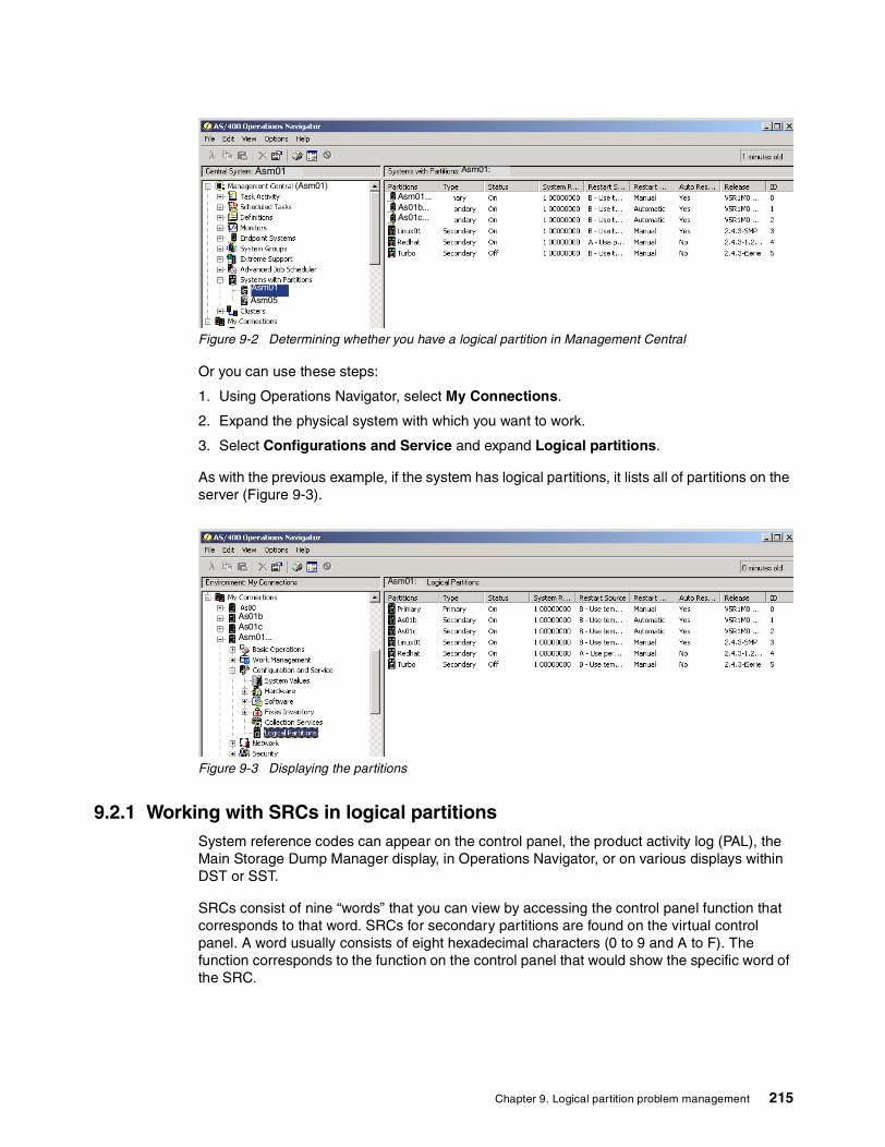
Figure 9-2 Determining whether you have a logical partition in Management Central
Or you can use these steps:
1. Using Operations Navigator, select My Connections.
2. Expand the physical system with which you want to work.
3. Select Configurations and Service and expand Logical partitions.
As with the previous example, if the system has logical partitions, it lists all of partitions on the server (Figure 9-3).
Figure 9-3 Displaying the partitions
9.2.1 Working with SRCs in logical partitionsSystem reference codes can appear on the control panel, the product activity log (PAL), the Main Storage Dump Manager display, in Operations Navigator, or on various displays within DST or SST.
SRCs consist of nine “words” that you can view by accessing the control panel function that corresponds to that word. SRCs for secondary partitions are found on the virtual control panel. A word usually consists of eight hexadecimal characters (0 to 9 and A to F). The function corresponds to the function on the control panel that would show the specific word of the SRC.
Asm01:Asm01(Asm01)
Asm01Asm05
Asm01...As01b...As01c...
Asm01...As01cAs01b
Asm01:
Chapter 9. Logical partition problem management 215

Figure 9-4 shows the Operations Navigator view of the primary SRC codes. This panel displays a list of the last 200 system reference codes sorted by date and time and from newest to oldest. To find a list of common SRCs and recovery actions related to logical partitions, refer to Appendix B, “System reference codes (SRCs) and messages” on page 397.
Figure 9-4 SRCs from Operations Navigator
You can display the SRCs for any partition. Figure 9-5 shows the same SRCs from a green screen.
Figure 9-5 SRCs from a green screen
Asm01As01bAs01c
216 LPAR Configuration and Management: Working with iSeries Logical Partitions

System reference codes at V4R5 and V5R1iSeries servers have a control panel that can display up to four words at the same time. In addition, the first word of the SRC can be any ASCII character. The other eight words of the SRC still consist of hexadecimal data.
In Figure 9-6, Function 11 displays the first word of the SRC. However, the first word can contain 8 to 32 characters.
Figure 9-6 Control Panel SRC display
Since you can display up to four words of the SRC at a time, the function you use to see the word is different for V4R5 and V5R1. Functions 11 through 13 show all nine words of the SRC. Functions 14 through 19 are not available.
In the PAL and other software displays, the SRC appears much like it does for earlier releases. One difference is that the first word has up to 32 characters of text. Another difference is that the word is a number from 1 to 9 instead of 11 to 19. This helps to avoid confusing the word number with the function number used to find it. The SRCs for V4R5 and V5R1 appear as shown in Table 9-1.
Table 9-1 SRC display on OS/400 V4R5 & V5R1
Function Word
11 1
expanded word 1
expanded word 1
expanded word 1
12 2
3
4
5
13 6
7
8
9
C6004500
Chapter 9. Logical partition problem management 217

System reference codes at V4R4For V4R4 hardware and software, the word number is the same as the function number to which it corresponds. For example, word 11 of the SRC appears in function 11. In the PAL and other software displays, the SRC appears as nine rows of hexadecimal data. Each row represents a function, and the word number displays in front of the hexadecimal data. The complete list of words and functions for V4R4 and earlier releases are shown in Table 9-2.
Table 9-2 SRC display on OS/400 V4R4
9.2.2 Viewing the product activity log for logical partitionsThe PAL contains a log of the system reference codes within a logical partition. Most SRCs display in the PAL for the logical partition that caused the SRC to appear. However, some SRCs may only appear in the PAL for the primary partition since it has the controlling authority over all other partitions. For example, SRCs resulting from processor or main storage problems appear in the PAL of the primary partition.
To view the PAL from Service Tools, from SST, perform the following steps:
1. Select option 1 (Start a service tool).
2. Select option 1 (Product Activity Log).
3. Select option 6 (Reference code description).
4. On the Select Reference Code Description display, enter:
– The Table ID: *ALL– Reference code: 0000– Output: 1 (Display)
Press Enter and the Display Reference Code Description appears as shown in Figure 9-7.
Function Word
11 11
12 12
13 13
14 14
15 15
16 16
17 17
18 18
19 19
218 LPAR Configuration and Management: Working with iSeries Logical Partitions

Figure 9-7 Product Activity Log display
From DST, perform the following steps:
1. Select option 7 (Start a service tool).2. Select option 6 (Product Activity Log).
Resolving system reference codes for logical partitionsIf a server with logical partitions experiences a configuration data error, the following indications occur:
� When you perform a normal mode IPL, system reference codes 1 A600 5090 and 3 0026 0000 display on the control panel. Restart the server by using a manual mode IPL. Check the product activity log (PAL) for specific SRCs.
� When you perform a manual mode IPL, the following messages appear:
– The “Unit has incorrect logical partition configuration” message appears instead of the sign-on display for Dedicated Service Tools.
– The “Configuration data errors detected - see Product Activity Log” message appears at the bottom of the Work with System Partitions display.
Check the PAL for specific system reference codes.
Chapter 9. Logical partition problem management 219

System reference codes Appendix B, “System reference codes (SRCs) and messages” on page 397, offers a list that contains the common SRCs that the PAL could report. Suggested corrective actions follow each SRC. If an SRC is not listed, it may not be related to logical partitions. You should consult your troubleshooting documentation or your next level of service.
9.3 Logical partition troubleshooting advisorThe iSeries Information Center has an LPAR troubleshooting advisor that can be used to find information pertaining to a specific system reference code. You can find the iSeries Information Center on the Web at: http://www.ibm.com/eserver/iseries/infocenter
Upon reaching this site, select Advisors-> Logical partition troubleshooting to start the LPAR troubleshooting advisor. Figure 9-8 shows the advisors Web page.
Figure 9-8 LPAR troubleshooting advisor
You can enter the system reference code, and the advisor will give you the cause and what recovery action to take for the problem. Figure 9-9 shows a result window from the advisor.
220 LPAR Configuration and Management: Working with iSeries Logical Partitions

Figure 9-9 LPAR troubleshooting advisor results
9.4 Working with configuration data for logical partitionsYou may need to work with logical partition configuration data. Typically, you need to do so in order to recover from hardware failures, to correct errors, or to perform maintenance after hardware movement. The server maintains the configuration data for all logical partitions on the load source of each logical partition. The configuration data maintained on the primary partition is considered the master copy. Problems can occur when the configuration information on the primary partition and a secondary partition conflicts, or after you initialize disk units during an installation. The following sections describe how to recover from errors and work with configuration data.
If you plan to migrate your data or recover a server with logical partitions, refer to iSeries Backup and Recovery V5R1, SC41-5304, for additional information.
9.4.1 Recovering logical partition configuration dataThe following information applies only to primary partitions. This procedure is part of a full server recovery, that is covered in iSeries Backup and Recovery V5R1, SC41-5304.
After you reinstall the Licensed Internal Code on the primary partition, stop at the IPL or Install the System display. Select option 3 (Use Dedicated Service Tools [DST]) to recover the logical partition configuration data. Then complete the following steps:
1. Before you change your disk configuration or recover your user ASPs, select option 11 (Work with system partitions).
2. Select option 4 (Recover configuration data).
3. Select option 1 (Recover primary partition configuration data). The server locates a nonconfigured disk unit that contains the most recent configuration data for your server. If
Attention:Use Dedicated Service Tools (DST) to work with configuration data for logical partitions.
Chapter 9. Logical partition problem management 221

the “No units found with more current configuration data” message displays instead of a list of resources, then no unassigned disk units contain any appropriate configuration information. Consult a service representative for assistance.
4. Verify that the date and the time fall within a valid time frame for the configuration.
5. Confirm your selection by pressing the Enter key.
6. The server copies the new configuration data to the primary partition’s load source and automatically restarts the primary partition.
7. When you next perform an IPL for the secondary partitions, the server updates their logical partition configuration data.
8. Once the primary partition completes its IPL, continue with any further recovery steps as outlined in the “Recovery” section of iSeries Backup and Recovery V5R1, SC41-5304.
9.4.2 Clearing partition configuration data for logical partitionsYou can clear the configuration data for:
� All logical partitions (delete all logical partitions)� Nonconfigured disk units (delete old configuration data on a disk unit)� Updating partition configuration data on all logical partitions
You can update the configuration data for every active logical partition by copying it manually from the primary partition to all active logical partitions. All inactive partitions will update automatically on their next restart. Perform this procedure from the Dedicated Service Tools or System Service Tools menu:
1. From DST, select option 11 (Work with system partitions). From SST, select option 5 (Work with system partitions). Press Enter.
2. Select option 4 (Recover configuration data).
3. Select option 2 (Update configuration data).
Confirm your choice by pressing the F10 key.
4. A service representative may ask you to restart your server to apply any changes.
9.4.3 Clearing partition configuration data from nonconfigured disk unitsWhen you move disk units among logical partitions or servers, you may need to erase any old configuration data before the server can use the logical partition again. You need to clear the configuration data when the disk unit has all of the following characteristics:
� A system reference code of B600 5311 displays in the product activity log against a nonconfigured disk unit.
� It is no longer a load source in its own logical partition.
� It is originally from a different logical partition where it was a load source, or it is from a different server that had logical partitions.
Attention: You should only perform these steps when instructed to do so by a service representative.
Attention: Using this function when the configuration data on the primary partition is incorrect ruins your existing configuration.
222 LPAR Configuration and Management: Working with iSeries Logical Partitions

Perform this procedure from a Dedicated Service Tools display:
1. Go to the DST menu.
2. Select option 11 (Work with system partitions).
3. Select option 4 (Recover configuration data).
4. Select option 3 (Clear non-configured disk unit configuration data).
5. Select the disk unit with the configuration data you want to erase. Type 1 in the Opt field to the left of the disk unit listing.
6. Press the Enter key.
7. Confirm that you truly want to erase the configuration data.
The changes take effect immediately.
9.4.4 Clearing nonreporting resources on logical partitions
After you add, remove, or move hardware within a server with logical partitions, you may have resources that are no longer available, that are listed twice, or that are no longer on the server. You can clean up these listings so that all nonreporting resources are erased from the configuration data for the logical partition. You do this from a Dedicated Service Tools display in the primary partition:
1. After you make all your hardware changes, restart your server in manual mode. Go to a DST menu in the primary partition.
2. Select option 11 (Work with system partitions).
3. Restart all secondary partitions in normal mode. Stop at the sign-on display for the operating system.
4. From the primary partition’s console, select option 4 (Recover configuration data).
5. Select option 4 (Clear non-reporting logical partitioning resources).
6. To confirm the deletion of nonreporting resources, press the F10 key.
9.4.5 Accepting a disk unit as load source for a logical partitionWhen configuration data on the load source of a logical partition is different from what the server expects, an error displays in the product activity log. A reference code of B600 5311 occurs against the load source disk unit. If you recently moved or added disk units either within the server or from another server, they may still contain configuration data. If you do not want to use one of them as the load source, you need to clear the configuration data before you proceed. Otherwise, if you do want to use one of the new disk units as your new load source on the logical partition, follow these steps from the Dedicated Service Tools menu:
1. At the DST menu, select option 11 (Work with system partitions).
2. Select option 4 (Recover configuration data).
3. Select option 5 (Accept load source disk unit).
Attention: Do not run this procedure if any hardware is marked as failed. Only run this procedure when all server hardware is completely operational.
Important: Wait until all secondary partitions complete their IPL before you continue to the next step.
Chapter 9. Logical partition problem management 223

4. Press the F10 key to confirm that you really want to use the disk as a load source in the logical partition. The server replaces the configuration data on the load source disk unit with the current configuration data.
The logical partition may now continue its IPL with the new load source disk unit.
9.4.6 Copying partition configuration data between IPL sourcesYour server may have experienced a disk read error of logical partition configuration data if the following system reference codes display when you restart from one IPL source but not another:
� B193 4511� xxxx xxx5D (where x equals any value 0 to 9 or A to F)� 690A 2060
You can copy the data from the functioning source to the faulty source with this procedure.
You should perform this procedure from a Dedicated Service Tools display:
1. If you are doing this on the primary partition, power off all secondary partitions. Otherwise, continue to the next step.
2. Restart your server in manual mode with the other IPL source (for example, source A if source B fails).
3. From DST, select option 11 (Work with system partitions).
4. Ensure that the configuration information contained on this IPL source is correct. Verify this by following the steps in Chapter 6, “Operating LPAR environments” on page 103. A correct configuration would show your most recent configuration of logical partitions. If it is correct, continue to the next step. If the configuration is not correct, do not continue. Consult a service representative.
5. Press the F3 key to return to the Work with System Partitions menu.
6. Select option 4 (Recover configuration data).
7. Select option 6 (Copy configuration data to other side).
8. Confirm your choice by pressing the F10 key.
9. Restart the logical partition using the other IPL source (source B, if source A had the correct configuration data you just copied from).
If you continue to have problems, contact a service representative.
9.4.7 Deleting all of your logical partitionsThere may be a time when you need to erase all your logical partitions to make the server non-partitioned again. It is possible to return all hardware resources to the primary partition. However, all user data contained within the secondary partitions will be lost. Make sure that you have adequate backups prepared for all logical partitions.
Important: You should only attempt this when you are certain that the logical partition restarts normally when using the other IPL source.
Attention: Following these instructions destroys all user data and system data on the secondary partitions.
224 LPAR Configuration and Management: Working with iSeries Logical Partitions

You can delete all logical partitions from the Dedicated Service Tools menu:
1. Perform a full server backup (option 21) for each logical partition, as described in iSeries Backup and Recovery V5R1, SC41-5304.
2. Power off all secondary partitions before you proceed.
3. Make sure that you are at the DST menu.
4. Select option 11 (Work with system partitions).
5. Select option 4 (Recover configuration data).
6. Select option 7 (Clear configuration data).
7. Confirm that you really want to delete all your logical partitions.
8. Restart the server in manual mode for the change to take effect.
9. Perform the steps for clearing configuration data from nonconfigured disk units from DST. Do this once for every former secondary partition load source disk unit.
10.Refer to iSeries Backup and Recovery V5R1, SC41-5304, for information on how to restore any user data or system data to the server.
9.5 Situations requiring the assistance of a service representative
Some troubleshooting tasks on the server require the assistance of a customer support representative. These tasks are not common and are only performed if the support representative deems it necessary. To prevent loss of data and damage to hardware, and to find a proper solution, contact your support representative before you attempt any of the following tasks:
� Performing main storage dumps on servers with logical partitions� Forcing a main storage dump on servers with logical partitions� Using remote service with logical partitions� Powering on and off a domain with logical partitions� Resetting a disk unit IOP with logical partitions
If you have to perform any of these tasks on your server, immediately contact the Technical Support Center for further assistance.
9.5.1 Performing main storage dump on servers with logical partitionsWhen your server performs a main storage dump, contact your customer support representative. When the server has a failure, it may create a main storage dump. A main storage dump copies the contents of the server’s main storage to disk. It can be an important tool for problem analysis. On a server with logical partitions, there are two types of failures that may cause main storage dumps: server failure and secondary partition failure.
Failures in the primary partition caused by server processing hardware or main storage hardware cause the entire server to fail. Software failures in a secondary partition cause only that logical partition to fail.
A server failure may cause a server main storage dump. A secondary partition failure may cause a main storage dump only on that logical partition.
Chapter 9. Logical partition problem management 225

9.5.2 Main storage dump of the serverYou should only perform a server main storage dump when directed by a service representative.
For more details on performing main storage dumps, refer to the Service Functions guide supplied softcopy on your supplementary manuals CD.
A Work with Partition Status display appears on the secondary partition’s console unless a main storage dump was already in progress. In that case, a Main Storage Dump display appears on the secondary partition console.
9.5.3 Main storage dump of a secondary partitionYou should only perform a secondary partition main storage dump if under the direction of a service representative. To perform a main storage dump on a secondary partition, you should be working with the remote control panel. Function 22 forces a main storage dump on the remote control panel. To display the remote control panel, follow these steps:
1. In Operations Navigator, expand Management Central.2. Expand Systems with Partitions.3. Select the physical system that has the logical partition with which you want to work.4. Right-click the logical partition and select Remote Control Panel.
In the event you cannot perform Function 22 (Force main storage dump) on a secondary partition, perform a system main storage dump under the direction of your service representative. When the Main Storage Dump Occurred display appears on the primary partition’s console, press Enter, and select option 6 (Dump all partitions).
9.5.4 Using remote service with logical partitionsOnly use this procedure when directed by your service representative.
Remote service is the method a service representative uses to access your server through a modem. The logical partition that is using remote service must have an electronic customer support communications IOP with a modem. If the communications IOP is on a shared bus and is used by another partition, switch the IOP to the partition that needs to use the modem. If this IOP also attaches to Operations Console, the console may be unavailable until the IOP is switched back to the original partition.
To use remote service with logical partitions, you should be working with the remote control panel. Function 66 activates the remote service, and Function 65 deactivates the service. Failure to deactivate the service could create a security risk. To display the remote control panel, follow these steps:
1. In Operations Navigator, expand Management Central.2. Expand Systems with Partitions.
Note: When you perform a server main storage dump, every active secondary partition also performs a main storage dump. Then they all restart. This may be a long running task.
Attention: It is a security risk to leave remote service enabled when not in use. This would allow someone to access your iSeries server without your knowledge. Ensure it has been deactivated when your service representative has finished using remote service.
226 LPAR Configuration and Management: Working with iSeries Logical Partitions

3. Select the physical system that has the logical partition with which you want to work.4. Right-click the logical partition and select Remote Control Panel.
9.5.5 Powering on and off a domain with logical partitionsOnly use this procedure when directed by your service representative.
You can power off and power on a domain when a disk unit IOP fails. When a disk unit IOP fails, the disk units in the IOP could become unusable, or the server could hang. The domain is a group of hardware resources that the system defines as being related. When you are under the direction of your service representative, perform a power off domain, the server shuts down the failed disk unit IOP. You can replace any failed disk units without restarting the logical partition or entire server.
To power off and power on a domain, you should be working with the remote control panel. Under the directions of your service representative, select Function 68 to power off the domain and Function 69 to power on the domain. To display the remote control panel, follow these steps:
1. In Operations Navigator, expand Management Central.2. Expand Systems with Partitions.3. Select the physical system that has the logical partition with which you want to work.4. Right-click the logical partition and select Remote Control Panel.
9.5.6 Resetting a disk unit IOP with logical partitionsOnly use this procedure when directed by your service representative.
Use this function to initiate an IOP dump and an IOP reset or an IOP reload. This function becomes enabled when certain disk unit SRCs appear and the associated IOP supports a reset or reload function.
To reset a disk unit IOP, you should be working with the remote control panel. Function 67 resets or reloads the disk unit IOP. To display the remote control panel, follow these steps:
1. In Operations Navigator, expand Management Central.2. Expand Systems with Partitions.3. Select the physical system that has the logical partition with which you want to work.4. Right-click the logical partition and select Remote Control Panel.
Attention: Incorrect use of this function can cause loss of data. It can also cause failures that may be incorrectly diagnosed as expensive hardware failures.
Chapter 9. Logical partition problem management 227

228 LPAR Configuration and Management: Working with iSeries Logical Partitions

Chapter 10. Interpartition communications
This chapter discusses the various choices and methods of setting up internal communications between the logical partitions. It covers the following topics:
� “External LAN” on page 230� “SPD OptiConnect” on page 230� “Virtual OptiConnect” on page 231� “High Speed Link OptiConnect” on page 231� “Virtual LAN” on page 232
10
© Copyright IBM Corp. 2002 229

10.1 What the options areThere are several communication options for logical partitions. They include the following types that are listed from the oldest to the newest choices:
� External LAN� SPD OptiConnect� Virtual OptiConnect� HSL OptiConnect� Virtual LAN
10.1.1 External LANThe traditional external LAN connections are available for interpartition communications. The 4 MB and 16 MB token-ring along with the 10 MB and 100 MB Ethernet LAN connections provide an easy to use method for any interpartition communications. If there are any concerns about the amount of LAN traffic, then you may want to consider some of the next options.
10.1.2 SPD OptiConnectThe first option, referred to as external OptiConnect, has been around for the iSeries and AS/400 for quite a while. An example of SPD OptiConnect is shown in Figure 10-1.
Figure 10-1 Older SPD OptiConnect that is still available on the iSeries
SPD OptiConnect is a combination of hardware and software that allows you to connect multiple high-end iSeries servers through a high-speed, fiber-optic bus. This combination of optical bus speed and efficient software makes OptiConnect a viable solution, providing multiple routes to the database. You can run both APPC or TCP/IP communications protocols over OptiConnect. Beginning with OS/400 V4R4, TCP/IP support was added to OptiConnect. To use OptiConnect, you must purchase the hardware and OptiConnect for OS/400 software.
For each logical partition that participates in external OptiConnect, you need a dedicated bus. You cannot assign this bus as shared.
740
5xx 6xx
S tandard
SPD bus
optical cables
730
230 LPAR Configuration and Management: Working with iSeries Logical Partitions
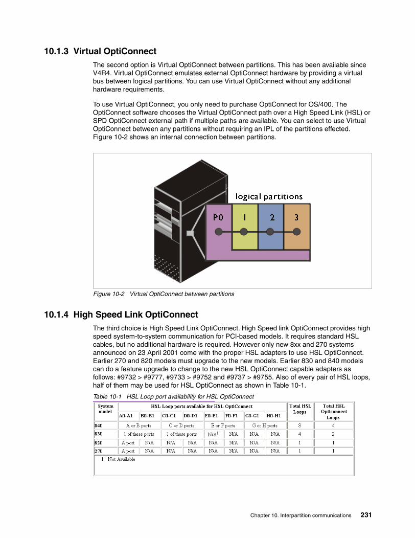
10.1.3 Virtual OptiConnectThe second option is Virtual OptiConnect between partitions. This has been available since V4R4. Virtual OptiConnect emulates external OptiConnect hardware by providing a virtual bus between logical partitions. You can use Virtual OptiConnect without any additional hardware requirements.
To use Virtual OptiConnect, you only need to purchase OptiConnect for OS/400. The OptiConnect software chooses the Virtual OptiConnect path over a High Speed Link (HSL) or SPD OptiConnect external path if multiple paths are available. You can select to use Virtual OptiConnect between any partitions without requiring an IPL of the partitions effected. Figure 10-2 shows an internal connection between partitions.
Figure 10-2 Virtual OptiConnect between partitions
10.1.4 High Speed Link OptiConnectThe third choice is High Speed Link OptiConnect. High Speed link OptiConnect provides high speed system-to-system communication for PCI-based models. It requires standard HSL cables, but no additional hardware is required. However only new 8xx and 270 systems announced on 23 April 2001 come with the proper HSL adapters to use HSL OptiConnect. Earlier 270 and 820 models must upgrade to the new models. Earlier 830 and 840 models can do a feature upgrade to change to the new HSL OptiConnect capable adapters as follows: #9732 > #9777, #9733 > #9752 and #9737 > #9755. Also of every pair of HSL loops, half of them may be used for HSL OptiConnect as shown in Table 10-1.
Table 10-1 HSL Loop port availability for HSL OptiConnect
logical partitions
1 2 31P0
Chapter 10. Interpartition communications 231

You may enable HSL OptiConnect to one other system per available loop. This allows for any partition in one system to communicate with any partition in the other system over a single loop. You must install OptiConnect for OS/400 software before this feature can be used. When you enable or disable HSL OptiConnect, the changes take effect immediately. Figure 10-3 shows two systems connected via HSL cables.
Figure 10-3 OptiConnect running over HSL between systems
10.1.5 Virtual LANThe last communication option between partitions is virtual LAN. Virtual LAN enables you to establish communication via TCP/IP between logical partitions. For each of the 16 ports enabled, the system creates a virtual LAN communications port, such as CMNxx with a resource type of 268C. Logical partitions assigned to the same LAN then become available to communicate through that link. A physical system allows you to configure up to 16 different virtual local area networks.
Virtual LAN provides the same function as using a 1 Gb Ethernet adapter. Token Ring or Ethernet 10 Mbps and 100 Mbps local area networks are not supported with virtual LAN. Virtual LAN requires V5R1 and can be used without any additional hardware or software. Virtual LAN works on any LPAR capable system (6xx, 7xx, Sxx, and 8xx) in V5R1 partitions. The only consideration is that this is TCP/IP only. Existing APPC communications like SNADS, DDM, and display station passthrough need to be revised to use the TCP/IP equivalents. Figure 10-4 shows the different virtual LAN connections between various partitions.
830
840
S tandard
HSL cables
232 LPAR Configuration and Management: Working with iSeries Logical Partitions

Figure 10-4 Two virtual LANs between partitions P0, 2, 5 and between 1, 3, 4
10.2 Planning considerations for interpartition communications
The biggest consideration for using any of the interpartition communication options is deciding which partitions need to exchange data. Some of the possible reasons to enable Virtual OptiConnect or virtual LAN may include some of the following examples:
� You might have multiple test partitions that would require moving programs from a development partition to a test partition and eventually to a production partition.
� One scenario may involve accessing a database in a different partition than the partition on which the application is running.
� Users accessing your iSeries server may be entering through a firewall application that is running on a Linux partition. They could be using the virtual LAN or Virtual OptiConnect to reach a Web server running in another partition that may be accessing data from a production system running on yet another partition.
The number of possible scenarios is really only limited by your LPAR environment and where the data is stored.
10.3 Implementing interpartition communicationsThere are two methods of implementing the interpartition communication options. The first is to use the traditional OS/400 5250 screens under DST or SST. The second method is to use the graphical user interface (GUI) in Operations Navigator. This section discusses both methods.
10.3.1 Traditional OS/400 communications using DST and SSTThe partitions that will use Virtual OptiConnect or virtual LAN need to be identified either at creation time or by going into the partition configuration screens and changing the communication options. The following displays show where you can enable the communications options. This change communications example was obtained by using these steps:
P0 1 2 3 4 5
logical partitions
2 virtual lans
Chapter 10. Interpartition communications 233

1. Sign on to the iSeries server with enough authority to manage partitions.
2. Type STRSST on command line.
3. Beginning at V5R1, you are prompted for a DST/SST user profile and password. This password is case sensitive.
4. Select option 5 to work with partitions as shown in Figure 10-5.
Figure 10-5 System Service Tools menu: Selecting option 5
5. Select option 3 to work with partition configuration as shown in Figure 10-6.
System Service Tools (SST) Select one of the following: 1. Start a service tool 2. Work with active service tools 3. Work with disk units 4. Work with diskette data recovery 5. Work with system partitions 6. Work with system capacity Selection 5 F3=Exit F10=Command entry F12=Cancel
234 LPAR Configuration and Management: Working with iSeries Logical Partitions

Figure 10-6 Selecting option 3 to work with partition configuration
6. Press the F23 key to see additional options on the work with partition configuration menu.
7. Type option 10 next to the partition for which you want to change the communications. You could click the F10 key to access the virtual LAN configuration displays by different functions and option keys. You must select two different partitions to enable communications between them. Figure 10-7 shows an example of using option 10 to change the communications options for partition 2 called AS01C.
Figure 10-7 Changing a partition’s communication options
Work with System Partitions System: M01 Attention: Incorrect use of this utility can cause damage to data in this system. See service documentation. Number of partitions . . . . . . . : 4 Partition manager release . . . . . : V5R1M0 L000 Partition identifier . . . . . . . : 0 Partition name . . . . . . . . . . : PRIMARY * Select one of the following: 1. Display partition information 2. Work with partition status 3. Work with partition configuration 4. Recover configuration data 5. Create a new partition Selection 3 F3=Exit F12=Cancel
Work with Partition Configuration System: M01 Type option, press Enter. 7=Select console resource 8=Select alternate IPL resource 9=Select default electronic customer support resource 10=Change comm options 11=Delete 12=Change oper env 13=Change host Partition Option Identifier Name 0 PRIMARY 1 AS01B 10 2 AS01C 3 LINUX1 F3=Exit F5=Refresh F9=Work with shared processor pool F10=Work with Virtual LAN configuration F11=Work with partition status F12=Cancel F23=More options
Chapter 10. Interpartition communications 235

8. Select which virtual LAN you want to use for the communications and if you want to use Virtual OptiConnect. Both are selectable choices. We enable both Virtual OptiConnect and virtual LAN as shown in Figure 10-8.
Figure 10-8 Enabling both Virtual OptiConnect and virtual LAN numbers 1, 14, and 15
10.3.2 Enabling interpartition communications options via GUIOperations Navigator is another method of enabling the interpartition communications options. This interface again requires proper authority to configure the Virtual OptiConnect and virtual LAN options. The following steps show you how to enable virtual LAN and virtual OptiConnect:
1. Start Operations Navigator within Client Access. Enter your user ID and password when prompted.
2. Expand the Configuration and Services entry and select the logical partitions entry as shown in Figure 10-9.
Change Communication Options System: M01 Partition identifier . . . . . . . . . . . . . : 2 Partition name . . . . . . . . . . . . . . . . : AS01C Type changes, press Enter. 1=Yes 2=No Connect to Virtual OptiConnect . . . . . . . . . 1 -------------------Virtual LAN Identifiers------------------- 0 1 2 3 4 5 6 7 8 9 10 11 12 13 14 15 1 2 2 2 2 2 2 2 2 2 2 2 2 2 1 1 F3=Exit F11=Display communication options F12=Cancel
236 LPAR Configuration and Management: Working with iSeries Logical Partitions

Figure 10-9 Operations Navigator Configuration and Services with logical partitions selected
3. Right-click on a partition and select the Properties entry.
4. Change the tab setting to show the options. You can enable or disable the Virtual OptiConnect between systems on this display as shown in Figure 10-10.
Figure 10-10 Options tab of the partition properties is used to change Virtual OptiConnect
5. You may have noticed, in Figure 10-10, that to change the virtual LAN connections, you must go to the physical system properties. Figure 10-11 shows the properties of the physical system, with the virtual LAN tab highlighted. Use this display to enable any virtual LAN connections that you may require.
Asm01:
Asm01
Asm27
Chapter 10. Interpartition communications 237

Figure 10-11 Virtual LAN tab communication configuration choices
This section has shown two methods of enabling communication options after a partition is created. The communication options between partitions could also be done at partition creation time.
10.4 Creating the interpartition connectionsThe previous section discussed enabling the partitions to communicate between themselves. This section explains how to create the necessary communication objects that any enabled partitions will need to establish a connection. It is assumed that TCP/IP has already been started in this example.
The virtual LAN connection uses a virtual communication resource. Communication resource type 268C is created within the partition where and when the virtual LAN is enabled. Figure 10-12 shows the new resource.
ASM01
238 LPAR Configuration and Management: Working with iSeries Logical Partitions

Figure 10-12 Communication resource CC01 is new for virtual LAN
The two standard communication tasks that need to be completed for virtual LAN to function are creating an Ethernet line description and assigning an IP address to that line description. You can use the Create Line Ethernet (CRTLINETH) command or menu option 5 on the WRKHDWRSC *CMN display to work with the configuration descriptions for the selected Ethernet Port resource. You can choose option 1 to create a new line description. The first available virtual resource is a 268C resource that shows a status of operational. We used CMN24 in our example. Figure 10-13 shows the virtual LAN line description with 1 Gb entered for the Line speed.
Figure 10-13 Creating an Ethernet line for the virtual LAN using the 268C virtual resource
Work with Communication Resources System: M01 Type options, press Enter. 5=Work with configuration descriptions 7=Display resource detail Opt Resource Type Status Text CMB01 2843 Operational Combined function IOP LIN01 2745 Operational Comm Adapter CMN01 2745 Operational V.24 Port CMN02 2745 Operational V.24 Port LIN04 2744 Operational LAN Adapter CMN04 2744 Operational Token-Ring Port CMB03 2843 Operational Combined function IOP LIN06 2744 Operational LAN Adapter CMN27 2744 Operational Token-Ring Port LIN03 2744 Operational LAN Adapter CMN25 2744 Operational Token-Ring Port CC01 268C Operational Comm Processor LIN02 268C Operational LAN Adapter CMN24 268C Operational Ethernet Port CMN20 268C Operational Ethernet Port More... F3=Exit F5=Refresh F6=Print F12=Cancel
Create Line Desc (Ethernet) (CRTLINETH) Type choices, press Enter. Line description . . . . . . . . > VETHLINE Name Resource name . . . . . . . . . > CMN24 Name, *NWID, *NWSD Online at IPL . . . . . . . . . *YES *YES, *NO Vary on wait . . . . . . . . . . *NOWAIT *NOWAIT, 15-180 seconds Local adapter address . . . . . *ADPT 020000000000-FEFFFFFFFFFF... Exchange identifier . . . . . . *SYSGEN 05600000-056FFFFF, *SYSGEN Ethernet standard . . . . . . . *ALL *ETHV2, *IEEE8023, *ALL Line speed . . . . . . . . . . . 1G 10M, 100M, 1G, *AUTO Duplex . . . . . . . . . . . . . *HALF *HALF, *FULL, *AUTO Bottom F3=Exit F4=Prompt F5=Refresh F10=Additional parameters F12=Cancel F13=How to use this display F24=More keys
Chapter 10. Interpartition communications 239

Next you assign an IP address to your new Ethernet virtual LAN line description. Go to the CFGTCP menu and select option 1 to work with interfaces. Figure 10-14 shows the generic IP address of 10.10.10.1 being assigned to the line VETHLINE in the primary partition.
Figure 10-14 Using a generic IP address for the virtual LAN line description
Finally, you vary on the virtual LAN Ethernet line description and start the IP interface. You need to repeat these steps on any partitions that have the virtual LAN enabled.
Add TCP/IP Interface (ADDTCPIFC) Type choices, press Enter. Internet address . . . . . . . . > '10.10.10.1' Line description . . . . . . . . VETHLINE Name, *LOOPBACK... Subnet mask . . . . . . . . . . 255.255.255.0 Associated local interface . . . *NONE Type of service . . . . . . . . *NORMAL *MINDELAY, *MAXTHRPUT... Maximum transmission unit . . . *LIND 576-16388, *LIND Autostart . . . . . . . . . . . *YES *YES, *NO PVC logical channel identifier 001-FFF + for more values X.25 idle circuit timeout . . . 60 1-600 X.25 maximum virtual circuits . 64 0-64 X.25 DDN interface . . . . . . . *NO *YES, *NO TRLAN bit sequencing . . . . . . *MSB *MSB, *LSB Bottom F3=Exit F4=Prompt F5=Refresh F12=Cancel F13=How to use this display F24=More keys
240 LPAR Configuration and Management: Working with iSeries Logical Partitions

Chapter 11. Configuring Linux in a guest partition
IBM and a variety of Linux distributors have partnered to integrate the Linux operating system with the reliability of the iSeries server. Linux brings a new generation of Web-based applications to the iSeries. IBM has modified the Linux PowerPC kernel to run in a secondary logical partition and contributed the kernel back to the Linux community.
This chapter contains information on how to plan a strategy that you can use to ensure Linux is successfully installed on your system, how to configure a guest partition to run Linux, and how to manage and troubleshoot a guest partition running Linux. It includes the following topics:
� “Planning to run in a guest partition” on page 242� “Creating a guest partition to run Linux” on page 251� “Managing Linux in a guest partition” on page 313� “Troubleshooting the iSeries with Linux running in a guest partition” on page 319
11
© Copyright IBM Corp. 2002 241

11.1 Planning to run in a guest partitionBefore you configure your iSeries for Linux, you need to carefully plan and evaluate your software and hardware resources. This section guides you through the planning process before you create a guest partition running Linux.
11.1.1 What is possibleIn line with IBM support for Linux, the iSeries provides the ability to run Linux natively on the iSeries server in a secondary partition. The primary partition must be running OS/400 V5R1, which provides the support required to boot the kernel in the secondary partition. The initial effort is to enable a fully functional Linux operating system to install and execute in a secondary iSeries partition. In the first release, the integration with OS/400 is minimal. Over time, the integration between OS/400 and Linux will be enhanced.
For those who are familiar with the Integrated xSeries Server for iSeries, the most basic support of Linux resembles the former product. The most notable difference being that Linux runs directly on the iSeries PowerPC hardware rather than on the integrated adapter running on an Intel processor.
Typically the latest stable version, patched version, and beta version are available. The stable version is the version that a production system would normally use. Versions that have an even number as the second digit are considered to be stable.
In regard to iSeries, the kernel must be at least 2.4, since the extensions were developed using that model. One other note is that 2.4 was available prior to the iSeries extensions. Therefore, the extensions may not be in a version acquired from the above location. However, it is something to keep in mind if you are considering building your own distribution. For the moment, it would be safest to acquire the distribution from one of the distributors who are working with IBM. At a later date, it should be possible to acquire the kernel and other pieces separately.
11.1.2 Who benefitsWhat are the advantages and disadvantages of this environment? The “i” in iSeries represents integration. It has supported the following environments:
� Intel processors on Integrated xSeries Server for iSeries– Windows NT– Windows 2000
� Domino� UNIX applications in the IBM iSeries PASE environment
And now this environment supports Linux.
Although the first release is aimed basically at installing a fully functional Linux server and running it in a secondary partition, there are still some scenarios that may be immediately appealing. Figure 11-1 illustrates a scenario that would use two Linux firewall partitions to establish a demilitarized zone all on the same hardware.
Attention: To run Linux on iSeries hardware, you must have installed OS/400 Version 5 or later in the primary partition. Linux is not enabled to run as the sole operating system on the iSeries server.
242 LPAR Configuration and Management: Working with iSeries Logical Partitions

Figure 11-1 Scenario using Linux partitions to create DMZ
Another scenario that may interest some is to use the Apache Web server that comes with most Linux distributions, although OS/400 will have the capability natively to be an Apache Web server.
Server consolidation is one of the primary attractions for this environment. The high-end hardware can support 31 Linux partitions and can provide access to a very large amount of DASD – 64 GB X 48 drives. This capacity enables the possibility of many other implementations:
� Partitions for testing Linux patches and applications before putting them into production� Hot swap servers (could maintain mirrored partitions to swap with a corrupted partition)� A form of Storage Area Network (SAN)� Clustered servers
In the first release, data transfer options to OS/400 internally are limited to FTP across the virtual Ethernet LAN. Database integration internally does not exist. Work is being done to enhance the communication between databases in particular and the integration between the two servers in general.
Linux applications can access the OS/400 database using socket programming and ODBC (at the time this redbook was written, this was in Beta). Also Apache on Linux is a very likely way to access the OS/400 application and data.
11.1.3 System requirementThe ability to divide the OS/400 into logically separate partitions that have their own resources and can concurrently run different copies of OS/400 (LPAR) has been available on the iSeries server since V4R4. It requires a primary partition running OS/400 to manage the other partitions. In the past, it was recommended that the primary partition be reserved exclusively for partition management. This was clearly not practical on a machine with two processors, or perhaps very desirable from the perspective of cost.
LinuxLinux LinuxLinuxOS/400OS/400OS/400OS/400 OS/400OS/400
Core Business App
ERP
SCM
ApacheWebSphereB2B ServerB2C ServerXML/WML
ApacheWebSphereB2B ServerB2C ServerXML/WML
InternetIntranetLAN Adapter LAN Adapter
Virtual LANs
DMZ
Firewall FirewallLoad- balance
Chapter 11. Configuring Linux in a guest partition 243

However, new processors and enhancements (as of V5R1) to the lower level code that mediates between the partitions now allow processors to be pooled and a fractional amount of a processor to be allocated to a partition from this pool. This is very desirable not only for the case mentioned above, for example, reserving the primary partition for partition management only. It is also a significant factor in implementing guest partitions since Linux may not require an entire processor for the workload it runs. OS/400 V5R1 enables the guest partition support that allows Linux to run directly on the iSeries hardware as a guest operating system. The following system requirements pertain to guest partition support:
� OS/400 version V5R1 or higher must be running in the primary partition. For more information on primary partitions or for detailed information on partitioning iSeries servers, see: http://www-1.ibm.com/servers/eserver/iseries/lpar/
� The iSeries server must be a more recent model of 270 or 8XX servers, which have SStar processors. Not all iSeries processors support Linux. See 2.1.3, “Partition support by model” on page 18, or the iSeries Information Center Web site at: http://publib.boulder.ibm.com/html/as400/infocenter.html
� At least 64 MB of memory and an amount of processor resources are required. Please note that 64 MB is the minimum requirement for a secondary partition. Due to some unique partitioning requirements for Linux, we recommend that, if you want to allocate a minimum of memory to the partition, this must be increased by a small amount. For example, 66 MB would suffice.
� To use the shared processor capability that allows processors to be pooled and assigned in fractional increments, the system must have particular processors.
� The machines with processors that do not support the shared processor capabilities must set the QPRCMLTTSK system value to “0” on the primary partition, which sets the value across all partitions. This could impact the performance of some applications running on OS/400. To verify this, use the command:
DSPSYSVAL SYSVAL(QPRCMLTTSK)
� The secondary partition that Linux is installed into is different than other secondary partitions as can be inferred by the fact that it must be defined as a guest partition. It is not specifically a Linux partition, but rather a guest partition. The intent is to allow a guest operating system to install on the iSeries platform and to operate independently of OS/400.
� The interactive processing feature cannot be allocated to a guest partition since Linux does not know about this feature.
� A maximum of 31 guest partitions can be defined.
Attention: How to partition a system is a subject that generates many opinions. The latest advice we received is that under some circumstances, there is no reason to dedicate the primary partition exclusively to partition management. In an environment in which the production workload is not distributed among independent concerns, each served by a separate partition, such as a service provider who services individual clients from dedicated partitions, then it is acceptable to use the primary partition for production. The debate may now be tempered further by the newly introduced capability to use a fraction of a processor for a partition as discussed below.
Attention: If the partition is defined to share processors, but the processor is not the correct type of processor, you do not receive a warning, and the guest partition will fail to start.
244 LPAR Configuration and Management: Working with iSeries Logical Partitions

� Optionally, LAN adapters, DASD, tape, and optical IOA can be dedicated to the Linux partition in native or direct attach mode, but not all IOA is supported in this manner. Be sure to check the Web site: http://publib.boulder.ibm.com/html/as400/infocenter.html
� If you plan to use the direct attached DASD referred to as “native” DASD in some publications, you require an IBM SCSI driver that is proprietary. Its name is ibmsis.o. It will be available on an IBM Web site as a “tarball”. This is a file that has been archived and compressed using Linux utilities and should be provided by the Linux distributors working with iSeries. The details of the distributions are not known at this time, but the driver or information regarding it should be available on the iSeries Web site as they become generally available.
� In addition, a Linux distribution that supplies the iSeries PowerPC extensions and install instructions is required. At this time, SuSE, Red Hat, and TurboLinux are working with iSeries to provide their software distributions.
11.1.4 Hosted versus nonhosted guest partition running LinuxEach operating system sharing the hardware can potentially provide benefits to the other that will only increase as the integration is enhanced over time. This implementation will be unique because it is PowerPC and it requires the existence of OS/400 in the primary partition to provide the mechanism for booting Linux initially on the hardware.
Two distinct environments are possible:
� Hosted environment� Non-hosted environment
Hosted environmentIn a hosted environment, Linux depends on the hosting OS/400 partition for some or all of its I/O. This environment is booted up and shut down from OS/400. The hosting OS/400 partition can either be a primary or a secondary partition.
To keep the primary partition workload at a minimum, IBM recommends that the hosting partition is not the primary partition. The I/O resources a guest partition can use from a hosted partition include disk, CD, and tape devices. The major advantage of this is the ability to save Linux data for emergency backup and access to large amounts of DASD.
A mixed environment – really a blend of the two extreme solutions – seems likely to be most popular. Native communications use dedicated LAN adapters, while the rest of the I/O is virtual. This would be the recommended solution for most environments. Such a “mixed” environment would actually be a subset of the hosted environment because any of the virtual services to DASD, CD-ROM, or communications require a network server description (NWSD) and, therefore, a hosting partition.
The hosted guest partition must be started from the hosting OS/400 partition using a NWSD. The NWSD is used to control the guest partition. The guest partition can only be active when OS/400 is both active and out of restricted state. When OS/400 is in a restricted state, all NWSDs are automatically varied off. An OS/400 partition can host multiple guest partitions.
You need to do proper capacity planning to ensure that the hosting partition can support a guest partition. You should IPL a hosted guest partition by varying on a NWSD object. You should not power on a hosted guest partition using the Work with Partitions Status display. If you power on the partition using the Work with Partitions Status display, all of the virtual I/O devices will be unavailable.
Chapter 11. Configuring Linux in a guest partition 245

Non-hosted environmentIn a non-hosted environment, all I/O is “native” and controlled by Linux. In the environment, Linux boots off of “native” DASD and does not depend on OS/400 after the installation, except for the very low-level partitioning code that all secondary partitions depend on. This has no affect on Linux, beyond the fact that IPLing the primary or the existence of a serious problem that brings down the primary partition will likewise bring down the Linux partition. But, this is also true for other secondary partitions.
A non-hosted guest partition does not depend on a hosting OS/400 partition for I/O resources. The guest partition has its own disk units, or the partition uses networking support to do a network boot. A non-hosted guest partition can be started even if the primary partition is not fully active. A nonhosted guest partition can be started from the Work with Partitions Status display.
11.1.5 Virtual I/O in a guest partition running LinuxTo create a Linux partition, you only need the processor and memory resources to be allocated to the partition. Obviously this would result in a non-functional server. The remaining resources can be supplied via virtual I/O from a hosting OS/400 partition. Of course, the iSeries does not have a diskette drive so that it is not available. Virtual I/O requires a hosting partition to be configured to supply the resources to the hosted partition. Virtual I/O resources are devices owned by the hosting OS/400 partition that provide I/O function to the guest partition. The iSeries Linux kernel and OS/400 support several different kinds of virtual I/O resources. They are virtual console, virtual disk unit, virtual CD, virtual tape, and virtual LAN.
Figure 11-2 illustrates how virtual devices work. They communicate via the hypervisor code to the device mapping functions of the host (OS/400) partition that direct the messages to or from the correct device. For example, a Telnet request to the Linux server is directed through the LAN adapter on the hosting OS/400 partition and routed by the OS/400 IP forwarding function through the internal LAN. Linux drivers pick up these messages on the virtual LAN and send them to the destination application. This is similar to the integration functions that allow the Windows NT server running on the Integrated xSeries Server for iSeries hardware to use the tape and optical drives on the OS/400. Note particularly the console mapper that enables the virtual console to connect to the guest partition.
246 LPAR Configuration and Management: Working with iSeries Logical Partitions

Figure 11-2 Overview of virtual I/O
Virtual console The virtual console provides console functions for the guest partition through an OS/400 partition. The virtual console can be established to the hosting partition or to the primary partition. The use of the virtual console allows the installation program to communicate with the user before the networking resources are configured. It can also be used for troubleshooting system errors. It provides a way to interact with Linux when it is being installed, or when TCP/IP has been configured incorrectly so that there is no access from the LAN. It can be accessed from a 5250 emulation screen or from a Telnet client on the network by Telnetting to port 2301 of the primary partition or hosting partition.
Virtual disk (NWSSTG)The virtual disk can only be provided by a hosting partition. It provides access to NWSSTG virtual disks from Linux. By default, the CRTNWSSTG command creates a disk environment with one disk partition formatted with the FAT16 file system. The virtual disk can be used to store the install image, the boot image, or configured to be additional user file systems. They can be as large as 64 GB and as many as 48 of them. The Linux installation program reformats the disk for Linux, or you can use Linux commands such as fdisk and mke2fs to format the disk for Linux.
Virtual CD The virtual CD is needed to support the installation of Linux and is only provided by a hosting partition. By default, a Linux partition can see all CD drives on the hosted partition. You can change an option on the NWSD to restrict Linux from accessing some or all of those drives. See 11.3, “Linux installation” on page 257, for more information on changing NWSD attributes. It can be shared with OS/400 and used to install Linux or to load other packages afterward.
Hypervisor
AS/400 Applications
OS/400
Disk I/O Processor
Disk I/O Processor
Comm I/O Processor
CDROM
SLIC
LAN Mapper Disk MapperCDROM Mapper
GNU Runtime
Linux Applications
Linux Kernel
CDROM DD
Disk DD
LAN DD
Console DD
Console Mapper
Chapter 11. Configuring Linux in a guest partition 247

Virtual tape The virtual tape provides access to the OS/400 tape drives from a Linux partition. By default, a Linux partition can see all tape drives on the hosted partition. You can change an option on the NWSD to restrict Linux from accessing some or all of those drives. See 11.3, “Linux installation” on page 257, for more information on changing NWSD attributes. The OS/400 tape drive can be used by Linux for Linux-based save/restore of files and directories in a hosted partition.
Virtual LANIt is desirable to have communication between partitions that are concurrently active. Virtual OptiConnect has been the mechanism for communicating between secondary partitions running OS/400. The guest partitions do not use this mechanism because Linux does not know about Virtual OptiConnect; therefore another mechanism was constructed, which is referred to as the virtual LAN. It is one of several virtual services available to the guest partition. It is not unique to the guest partition, but it is the only inter-partition communication available to guest partitions. It is currently the only mechanism for transferring data between the OS/400 and the Linux partition directly.
Technically it is possible to configure in 16 virtual LANs from the LPAR configuration screens. The virtual LAN itself is not an actual physical connection, but emulates a 1 Gb Ethernet LAN.
11.1.6 Direct attached I/O in a guest partition running LinuxWith direct attached I/O, Linux manages the hardware resources directly and all resources associated under the adapter. You can allocate disk units, tape devices, optical devices, and LAN adapters to a guest partition running Linux.
You must have a NWSD to install Linux in a guest partition. Once Linux is installed, you can configure the partition to start independently.
For integrated hardware, all failure and diagnostic messages are displayed within the guest partition.
Alternatively the user may want to achieve minimal dependence upon the OS/400 and maximum separation of resources so that all I/O to the Linux partition is under control of the Linux operating system and the server boots independently of the other partitions. In this case, they can configure a non-hosted guest partition by allocating disk, CD-ROM, tape drive, and LAN adapters as direct attached IOAs, controlled by the Linux operating system, and then installing Linux to the native disk. The initial installation requires assistance from the OS/400 partition to load the kernel and kick off the install. After Linux is installed, the kernel can be stored in such a way as to exclude hosted assistance. It can then be IPLed from its own virtual service panel.
Attention: The virtual LAN is analogous to the internal LAN that was used by several of the Integrated Netfinity Server products. A common misconception in the later case was that the internal LAN was a physical adapter. The virtual LAN is not the internal LAN, but it also is not a physical adapter.
Attention: Although Linux controls the I/O, the partition still relies on the primary partition and hypervisor for low-level services. If the primary is IPLed, for example, the guest partitions and secondary partitions will likewise be brought down or IPLed depending on the way they were defined. Also a failure in the primary that causes it to abend will likewise terminate the guest partitions.
248 LPAR Configuration and Management: Working with iSeries Logical Partitions

Installing the partition requires a NWSD. But once the installation completes, the partition can be configured to boot independently, and the NWSD is no longer required to be used.
This configuration is not unconditionally recommended because it is slightly more difficult to configure LPAR. The diagnostics are more limited from an OS/400 perspective since most of the error logging occurs in Linux itself. Intermittent hardware failures can be very difficult to diagnose.
The non-hosted partition is an example in which all I/O would be driven by Linux and the OS/400 only responsible for protecting the integrity of the partitions resources from other partitions. It is an extreme example that may be used for particular environments such as firewalls. However a more likely scenario that appeals to many is to use the directly attached communications adapters. This is opposed to routing the communications across the virtual LAN and out an adapter on the hosting partition while using the virtual disk and virtual optical on a hosted partition. Other mixed environment combinations are possible, but we do not discuss them here. Figure 11-3 shows a network with a Linux partition that is non-hosted. It shows a directly attached IOA that communicates with the Linux device drivers rather than being mapped to a device via the virtual services as pictured in Figure 11-2.
Figure 11-3 Direct attached IOA (native)
11.1.7 Identifying I/O adapters in a guest partitionIOAs may be assigned to a guest partition. The partition configuration user interface will identify resources owned by a guest partition as empty positions, occupied positions, or generic adapters.
An empty position means no IOA is installed in a position. An occupied position means an IOA is installed, but not owned by a guest partition. A generic adapter identifies an IOA that is owned by a guest partition. Generic adapter resources will either have a CCIN number, or they will be identified as type 274D or a 274E.
Hypervisor
AS/400 Applications
OS/400
Disk I/O Processor
Disk I/O Processor
Comm I/O ProcessorCDROM
SLIC GNU Runtime
Linux Applications
Linux Kernel
CDROM DD
Disk DD
LAN DD
Console DD
Native Linux device drivers enabled by Kernelchanges for iSeries LPAR support
Existing Linux device drivers will be used wherethey apply to iSeries hardware
1 new SCSI PCI IOA device driver written to support an iSeries unique adaptor and it's interfaceprotocol (SIS)
Chapter 11. Configuring Linux in a guest partition 249

11.1.8 iSeries I/O adapters supported by LinuxIOAs may be assigned to a guest partition. Table 11-1 shows the adapters that are supported by iSeries in a guest partition running Linux.
Table 11-1 iSeries I/O adapters supported by Linux
The Linux acenic, olympic, and pcnet32 device drivers are available with Linux. These drivers are compiled into the kernel and are available from your preferred Linux distributor.
The ibmsis driver provides an interface for the operating system to communicate with tape, optical, and disk unit devices. This device driver is compiled into the kernel and is available from your preferred Linux distributor. You can find any updates to this device driver at the Linux for iSeries Web site at: http://www-1.ibm.com/servers/eserver/iseries/linux/
This list may change between OS/400 release boundaries. Refer to the Linux for iSeries Web site for any additional IOAs supported by Linux.
11.1.9 Obtaining Linux for iSeriesLinux is an open source operating system. It can be obtained in source format and built by individuals or business organizations. This open source code encourages feedback and further development by programmers. Linux developers are encouraged to design their own specialized distribution of the operating system to meet their specific needs and to freely offer their source code to the Linux community for potential inclusion. If you want to develop your own distribution of Linux, Linux from Scratch is a good source of information. You can find Linux from Scratch on the Web at: http://www.linuxfromscratch.org/
Adapters (CCIN)
Feature codes
Description Linux device driver
SubSystem vendor/sub-system type
PCI vendor ID/PCI ID
2743 0601 1 Gbps Ethernet (fibreoptical) acenic 1014/0104 12AE/0001
2760 0602 1 Gbps Ethernet UTP (unshielded twisted pair)
acenic 1014/00F2 12AE/0001
2744 0603 100/16/4 Mbps Token Ring olympic 1014/016D 1014/003E
2838 0607 100/10 Mbps Ethernet pcnet32 1014/0133 1022/2000
2748 0605 Ultra-2 SCSI (3 buses; 26 MB write cache; extended adaptive read cache; supporting internal disk and tape units, CD-ROM, and DVD-RAM)
ibmsis 1014/0099 1014/0096
2763 0604 Ultra-2 SCSI (2 buses; 10 MB write cache; supporting internal disk and tape units, CD-ROM, and DVD-RAM)
ibmsis 1014/0098 1014/0096
2778 0606 Ultra-2 SCSI (3 buses; 78 MB write cache; extended adaptive read cache; supporting internal disk and tape units, CD-ROM, and DVD-RAM)
ibmsis 1014/0097 1014/0096
Note: The 2766 is not supported by LINUX as a directly attached IOA.
250 LPAR Configuration and Management: Working with iSeries Logical Partitions

Currently, IBM is working with the major distributors of Linux, including Red Hat Linux, SuSE Linux, and TurboLinux. Each of these distributors will provide the iSeries PowerPC kernel. All Linux distributions share a similar Linux kernel and development library. Linux distributors provide custom components that ease the installation and maintenance of Linux systems. Before installing another distributor’s version of Linux, verify that the kernel has been compiled for PowerPC and the iSeries hardware. Otherwise, your system may be misconfigured and will not run Linux in a guest partition.
Many of the distributors will provide either an Internet download or a CD-ROM version of Linux. Refer to the Linux for iSeries Web site (http://www-1.ibm.com/servers/eserver/iseries/linux/) for links to each distributor.
11.1.10 Ordering a new server or upgrading an existing server to run LinuxRefer to the Linux for iSeries Web site for information on the LPAR Validation Tool (LVT). You can contact your IBM marketing representative or IBM Business Partner to enter the order. Or you can enter the order by using the iSeries configurator. The configurator has been enhanced to support ordering IOAs without IOPs when a Linux partition is being defined.
When placing the order for a server with resources that support Linux in a guest partition, specify feature code 0142.
11.2 Creating a guest partition to run LinuxBefore you start to configure a partition on your iSeries to run Linux, see 11.1, “Planning to run in a guest partition” on page 242, for assistance. You should also be familiar with basic logical partitions concepts before you start to create a guest partition. This section guides you through the necessary steps to install Linux on the iSeries.
We recommend that you perform a full system backup before you change your system configuration. Refer to Linux on the IBM ~ iSeries Server: An Implementation Guide, SG24-6232.
11.2.1 Creating a guest partition on your iSeriesWhen you create a guest partition, you should be running a non-OS/400 operating system in an iSeries partition. If you are not familiar with logical partitions on an iSeries server, you should start with Chapter 2, “Understanding logical partitioning” on page 15. Installing Linux in a guest partition involves configuring a partition to support the guest operating system.
Before you configure a guest partition, you need to remove resources for the partition. Refer to Chapter 4, “Logical partition setup” on page 63.
Now follow these step-by-step instructions to configure a guest partition on the iSeries:
1. Start System Service Tools (STRSST) from the primary partition. This requires *SERVICE authority. Select option 5 (Work with system partitions) as shown in Figure 11-4.
Chapter 11. Configuring Linux in a guest partition 251

Figure 11-4 System Service Tools
2. On the Work with System Partitions display (Figure 11-5), select option 3 (Work with partition configuration). On a new system, there would be only the primary partition. Therefore, it would own all the resources. To allocate resources that are owned by the partition, the resources are removed from the partition that owns them before they are added to the new partition.
Figure 11-5 Work with System Partitions
3. On the next display (Figure 11-6), choose 5 to create a new partition.
System Service Tools (SST) Select one of the following: 1. Start a service tool 2. Work with active service tools 3. Work with disk units 4. Work with diskette data recovery 5. Work with system partitions 6. Work with system capacity
Selection
F3=Exit F10=Command entry F12=Cancel
Work with System Partitions System: AS05 Attention: Incorrect use of this utility can cause damage to data in this system. See service documentation. Number of partitions . . . . . . . : 4 Partition manager release . . . . . : V5R1M0 L000 Partition identifier . . . . . . . : 0 Partition name . . . . . . . . . . : PRIMARY * Select one of the following: 1. Display partition information 2. Work with partition status 3. Work with partition configuration 4. Recover configuration data 5. Create a new partition Selection F3=Exit F12=Cancel
252 LPAR Configuration and Management: Working with iSeries Logical Partitions

Figure 11-6 Work with System Partitions
4. On the Select Operating Environment display (Figure 11-7), choose 2 (Create a Guest partition).
Figure 11-7 Selecting to configure a guest partition
5. On the Create New Partition display (Figure 11-8), specify:
a. A name for the partition. Any name that is appropriate or meaningful to your environment will do.
b. A numeric partition number (a primary partition is always “0”).
c. Specify the number of processors for this partition:
• For whole processors, specify a number of processors out of the number available. Note when this system was new, three processors would have been available, and we could have selected 1, 2, or 3.
Work with System Partitions System: AS05 Attention: Incorrect use of this utility can cause damage to data in this system . See service documentation. Number of partitions . . . . . . . : 4 Partition manager release . . . . . : V5R1M0 L000 Partition identifier . . . . . . . : 0 Partition name . . . . . . . . . . : PRIMARY * Select one of the following: 1. Display partition information 2. Work with partition status 3. Work with partition configuration 4. Recover configuration data 5. Create a new partition Selection F3=Exit F12=Cancel
Select Operating Environment System: AS05 Select one of the following: 1. OS/400 2. Guest Selection 1 F3=Exit F12=Cancel
Chapter 11. Configuring Linux in a guest partition 253

• To use shared processors, F10 allows you to define the processor pool and when you select 1 (Yes) for “Use shared processor pool”, you are prompted to enter the fractional amount.
d. Enter the size of the partition main storage (a minimum of 64 MB; the recommended minimum for Linux is 66 MB.)
Figure 11-8 Create New Partition
6. On the Select Communication Options display (Figure 11-9), specify the virtual LAN port for the partition. LAN 0 is selected in this case, but you could select any of them.
Figure 11-9 Configuring for virtual LAN
7. On the Confirm New Partition display shown in Figure 11-10, press Enter to confirm your selection.
Create New Partition System: AS05 Complete blanks, press Enter. Partition identifier and name . . . . . . . . . 2 SUSE Number of available system processors . . . . : 0 Number of partition processors . . . . . . . . . 1 Use shared processor pool . . . . . . . . . . . 1 1=Yes, 2=No Shared processor pool units . . . . . . . . . 0 . 50 Size of available system main storage (MB) . . : 1024 Size of partition main storage (MB) . . . . . . 1024
F3=Exit F9=Include limits F10=Work with shared processor pool F11=Display partition processing configuration F12=Cancel Enter value for shared processor pool units.
Select Communication Options System: AS05 Partition identifier . . . . . . . . . . . . . : 4 Partition name . . . . . . . . . . . . . . . . : LINUX1 Type changes, press Enter. 1=Yes 2=No -------------------Virtual LAN Identifiers------------------- 0 1 2 3 4 5 6 7 8 9 10 11 12 13 14 15 1 2 2 2 2 2 2 2 2 2 2 2 2 2 2 2 F3=Exit F11=Display communication options F12=Cancel
254 LPAR Configuration and Management: Working with iSeries Logical Partitions

Figure 11-10 Confirming your selection
8. On the Work with Partition Configuration display (Figure 11-11), specify a hosting partition. You need to select F23 (More Options). If this was to be a non-hosted partition, it would not be necessary to specify a host.
Figure 11-11 Work with Partition Configuration
Confirm New Partition System: AS05 Verify information, press Enter. Partition identifier and name . . . . . . . . : 2 SUSE Number of partition processors . . . . . . . . : 1 Minimum / maximum number of processors . . . . : 1 / 1 Use shared processor pool . . . . . . . . . . : Yes Shared processor pool units . . . . . . . . : 0.50 Minimum / maximum processor pool units . . . : 0.10 / 0.50 Size of partition main storage (MB) . . . . . : 1024 Minimum / maximum size of main storage (MB) . : 86 / 1024 Virtual LAN . . . . . . . . . . . . . . . . . : Yes I/O Resource Serial Part Description Type-Model Number Number F3=Exit F9=Select host partition F10=Display logical address F11=Add I/O resources F12=Cancel
Work with Partition Configuration System: AS05 Type option, press Enter. 1=Change partition name 2=Change partition processing resources 3=Add I/O resources 4=Remove I/O resources 5=Change bus ownership type 6=Select load source resource Partition Option Identifier Name 0 PRIMARY 1 AS05B 2 SUSE
F3=Exit F5=Refresh F9=Work with shared processor pool F10=Work with Virtual LAN configuration F11=Work with partition status F12=Cancel F23=More options
Chapter 11. Configuring Linux in a guest partition 255

9. On the next display (Figure 11-12), select option 13 (Change host).
Figure 11-12 Work with partition configuration
10.The Change Host Partition display appears as shown in Figure 11-13. A list of partitions available to host the Linux partition is presented. The primary and a secondary partition (AS05B) are available. You can select each of them as the host. In this case, you would enter a 1 next to AS05B to select it as the host.
Figure 11-13 Selecting the host partition
11.Verify that the host partition is configured for the virtual LAN as shown in Figure 11-14. We selected LAN 0 because it was the first one available in sequence, but there is no particular reason that it had to be “0”. It does not have to be selected at all, except that there would be no communication between partitions if it was not. If it were necessary to absolutely isolate the partition, not configuring the internal LAN would do that. However, there would be no user interface to the partition from other partitions if this were done.
Work with Partition Configuration System: AS05 Type option, press Enter. 7=Select console resource 8=Select alternate IPL resource 9=Select default electronic customer support resource 10=Change comm options 11=Delete 12=Change oper env 13=Change host Partition Option Identifier Name 0 PRIMARY 1 AS05B 2 SUSE F3=Exit F5=Refresh F9=Work with shared processor pool F10=Work with Virtual LAN configuration F11=Work with partition status F12=Cancel F23=More options
Change Host Partition System: AS05 Partition identifier . . . . . . . . . . . . . : 2 Partition name . . . . . . . . . . . . . . . . : SUSE Type option, press Enter. 1=Select -----------Host Partition------------ Option Identifier Name Version/Release 0 PRIMARY V5R1M0 L000 1 AS05B V5R1M0 L000 *
* Indicates current host. F3=Exit F12=Cancel
256 LPAR Configuration and Management: Working with iSeries Logical Partitions

Partitions can belong to more than one internal LAN. Finally if there are multiple Linux partitions on the same virtual LAN, they can share the same subnet.
12.If the partition does not show up press F10. If the hosting partition is not connected, choose option 2 (Change) and then add it to the virtual LAN.
Figure 11-14 Checking that the primary partition is connected to the virtual LAN
11.3 Linux installationBefore you install Linux on a partition, you need to configure your iSeries to run Linux. See 11.2, “Creating a guest partition to run Linux” on page 251, for more information on configuring Linux in a guest partition.
IBM is currently working with partners who will support Linux on an iSeries. Your preferred Linux distributor will provide specific documentation on how to install Linux on the iSeries.
Choosing a distributionThe following considerations apply when choosing a distribution or acquiring the elements to create your own distribution, which is also possible but not advisable at this time:
� IBM is currently working with the following distributors to provide the distribution of the iSeries PowerPC extensions. Details are not available at this time:
– SuSE– Red Hat – TurboLinux
� You need a PowerPC-enabled version of the kernel.
– Kernel version 2.4 or later. The exact version numbers won’t be available until the distributions are available, but will have to be version 2.4 or higher because that was the most current supported version of the kernel at the time that the enabling code was being developed.
– Check the iSeries Web site and the distributions for supported versions.
– iSeries drivers must be included in the distribution. This will be true of the three distributors above. One driver of note is the proprietary driver to interface to the SCSI devices which is ibmsis.o. It should be available with the same distributions, but if not, check for it as a tarball on the iSeries/Linux Web site: http://www-1.ibm.com/servers/eserver/iseries/linux/
Work with Virtual LAN Configuration System: AS05 Type options, press Enter. 2=Change Par -------------------Virtual LAN Identifiers------------------- Opt ID Name 0 1 2 3 4 5 6 7 8 9 10 11 12 13 14 15 0 PRIMARY . . 1 . 1 . . . . . . . . . . 1 AS05B 1 . 1 . 1 . . . . . . . . 2 SUSE 1 . . . . . . . . . . . .
'1' Indicates LAN in use. '.' Indicates LAN not in use. F3=Exit F9=Show all partitions F11=Display communication options F12=Cancel
Chapter 11. Configuring Linux in a guest partition 257

About the installation processAdditional setup up front is required to install Linux on iSeries, as compared to other computers. As has been noted, Linux cannot be installed as the only operating system on an iSeries server, but it must be installed in a secondary partition of a system running OS/400 V5R1 in the primary partition. Another fundamental difference when installing Linux on the iSeries server results from the difference between the way in which OS/400 is loaded as opposed to other computers that use BIOS.
To begin installing the software in the case of Linux, it wants to install information into the master boot record (MBR) so that the system boots to the Linux’s boot loader on a partition marked as “bootable”. After the installation, Linux wants Linux Loader (LILO; its boot loader) to boot the kernel. On other systems, Linux can be installed to boot from another boot loader such as System Commander or Partition Magic. Alternatively it can boot other operating systems.
Since iSeries hardware has only needed to boot OS/400 until now, there is no generic process for loading and installing operating systems other than OS/400. Therefore, there needs to be a process to load the kernel into the partition, initialize it, and link to the root file system in order to start the rest of Linux or, in the case of the installation, to run the install scripts. The mechanism to do this initially is the network server description. This is true for the installation of both hosted and non-hosted environments. The NWSD would reside on the hosting partition or the primary partition if it was only to used for the initial installation.
After the initial installation, the NWSD remains the mechanism for booting Linux into a “hosted” partition and indeed for IPLing that partition. However, subsequent boots into a non-hosted environment would no longer require the NWSD and would be booted using the Virtual Service Panel for the partition. This is because the primary partition must still provide the “loading mechanism” for Linux. The objects and processes described in the following sections may be involved in any of the installation processes and used routinely when the Linux partition is using the virtual services described in the next section.
Create a Network Server Description (CRTNWSD)A network server description is used to give a name to the configuration, provide an interface for starting and stopping a Linux partition, and provide a link between Linux and its virtual disks. The command is CRTNWSD, which is shown in Figure 11-15. The important parameters that are used in this command are:
� Create NWSD on your hosting partition: AS05B
� Network server description: The name of the NWSD (in this example Linux1)
� Resource name: *NONE (means you do not reference physical resources)
� Network server type: *GUEST
� Online at IPL: *NO (could be set to *YES)
� Partition: The name of partition into which Linux will be installed (SUSE in this example)
� Code Page: 437 (the default *LNGVER is not supported; must enter a specific code page)
258 LPAR Configuration and Management: Working with iSeries Logical Partitions

Figure 11-15 Create Network Server Description
Booting Linux on iSeriesThe following parameters in the network server description control from where the Linux kernel will be booted. See Figure 11-16.
� IPL source: This is set to *NWSSTG in this example. This parameter defines where the kernel is located from which the server will be booted and has the following options:
– *NWSSTG means that the boot source is a virtual disk associated with the NWSD and a local hard drive as far as the server knows. It must have a partition formatted as a primary partition of type “PReP Boot” (type 0x41) marked as bootable. In this later scenario, varying on the server brought up Linux without going through the installation since the installation had been previously done on the source machine.
– *STMF means the boot source is a file in the Integrated File System (IFS) of the OS/400 partition. Therefore, the kernel is read out of a stream file. This could include a CD-ROM that would be mounted into the Integrated File System on iSeries under the QOPT directory and is most likely what will be used to install from CD-ROM.
– A or B means the Linux system boots from slot A or B. The semantics are derived from the iSeries IPL options that allow different copies of OS/400 to be loaded. In this case, the slots are actually in Linux itself and the kernel must be loaded into them from Linux. To do this, the /proc file system is used with a command similar to:
dd if=/usr/src/linux/vmlinux of=/proc/iSeries/mf/A/vmlinux
The advantage of doing this would be a faster bootup, but there may be disadvantages also, among which is that it can’t be save and restored.
Create Network Server Desc (CRTNWSD) Type choices, press Enter. Network server description . . . . > LINUX1 Name Resource name . . . . . . . . . > *NONE Name, *NONE Network server type . . . . . . . > *GUEST *WINDOWSNT, *GUEST Online at IPL . . . . . . . . . *no *YES, *NO Vary on wait . . . . . . . . . . *NOWAIT *NOWAIT, 1-15 minutes Partition . . . . . . . . . . . SUSE Name Code page . . . . . . . . . . . 437 *LNGVER, 437, 850, 852, 857... Server message queue . . . . . . *JOBLOG Name, *JOBLOG, *NONE Library . . . . . . . . . . . Name, *LIBL, *CURLIB TCP/IP port configuration: Port . . . . . . . . . . . . . *NONE *NONE, *INTERNAL, 1, 2, 3 Internet address . . . . . . . Subnet mask . . . . . . . . . Maximum transmission unit . . Number + for more values More... F3=Exit F4=Prompt F5=Refresh F12=Cancel F13=How to use this display F24=More keys
Chapter 11. Configuring Linux in a guest partition 259

– *PANEL means that in the SST Partition Configuration panel, you must specify which IPL source to use.
– The other values are reserved.
� IPL stream file: This is the path to the stream file that which the server would boot from when *STMF is specified as the IPL source.
� IPL parameters: This offers a way of giving boot time parameters to a Linux system, such as can be specified at the LILO prompt on a PC Linux system.
Figure 11-16 Boot or IPL parameters for the Linux partition
A network server description can be viewed and its status determined by using the command WRKCFGST *NWS. From the status display, the NWSD can be varied on or off. Please note that this process is the required way to IPL the partition for a hosted partition.
NWSD parameter and descriptionsTable 11-2 describes each parameter value and how each parameter is used when running a guest partition. It can help you to understand how to create a NWSD for a guest partition.
Table 11-2 NWSD parameter and descriptions
Create Network Server Desc (CRTNWSD) Type choices, press Enter. Ports: Port number . . . . . . . . . *NONE 1, 2, 3, *INTERNAL, *NONE Line description . . . . . . . Name + for more values Synchronize date and time . . . *TYPE *TYPE, *YES, *NO IPL source . . . . *NWSSTG *NWSSTG, *PANEL, *STMF, A... IPL stream file. . . . *NONE IPL parameters. . . . *NONE Authority . . . . . . . . . . . *LIBCRTAUT Name, *LIBCRTAUT, *CHANGE... Text 'description' . . . . . . . *BLANK Bottom F3=Exit F4=Prompt F5=Refresh F12=Cancel F13=How to use this display F24=More keys
Attention: If you IPL a hosted partition from the LPAR status green screen or the partition is IPLed as a result of an IPL of the primary partition, the NWSD vary on will fail. To correct this, simply return to the LPAR status green screen, shut down the hosted partition, and then vary on the NWSD again.
Prompt Parameter Parameter description
Network server description
NWSD The name that you give the network server description. It is recommended to use the same name as your partition. You can create multiple NWSDs that point to the same partition. In this case, you can have a set for each Linux distributor. Only one NWSD can be active at a time, but you can create multiple NWSDs for each partition.
260 LPAR Configuration and Management: Working with iSeries Logical Partitions

Resource name
RSRCNAME Specifies the resource name that identifies the hardware that the description represents. This option does not apply to a *GUEST partition.
Network server type
TPYE This specifies which type of network description to create.
Online at IPL ONLINE Specifies whether this object is automatically varied on at initial program load (IPL).
Vary on wait VRYWAIT Specifies whether the network server description is varied on asynchronously or synchronously. For a synchronous vary on, specifies how long the system waits for the vary on to complete.
Partition PARTITION The name of the partition given during the configuration of a guest partition. If you provide the incorrect name of a partition here, it will not be detected until you vary on the NWSD,
Code page CODEPAGE The ASCII code page represents the character set Linux uses and that OS/400 assumes the Linux console is using.
Message queue
MSGQ Species the name of a message queue to receive server console messages.
TCP/IP port configuration
TCPPORTCFG Setting the TCP/IP information does not cause any configuration to occur on OS/400. All information entered here is made available to Linux in /proc/iSeries/config. The intent is that the configuration scripts can automatically read the file and set up your Linux partition. Currently, these scripts do not exist. There is a feature that prevents the TCP/IP route configuration from showing up on the CRTNWSD screen. Select option F9 to make the configuration options appear.
Restricted device list
RSTDDEVRSC A guest partition running Linux has access to all optical and tape devices in the hosting partition. To restrict Linux from using any of these devices, use this feature.
Synchronize date and time
SYNCTIME Specifies whether the iSeries should synchronize the network server date and time with the iSeries server date and time. As with the TCP/IP configuration, this parameter is reflected in the /proc/iSeries/config file.
IPL sources IPLSRC This parameter specifies from where the Linux kernel will be loaded.
IPL stream file IPLPARM Specifies the path from which the kernel is to load. The user running the vary on command must have read access to the file and the path leading to the file.
IPL parameters
IPLPARM Specifies a string of characters that will be passed to the load image at IPL time. It consists of commands or configuration information for the kernel.
Authority AUT The system determines authority for the object using the value specified for the create authority prompt for the library in which the object is created.
Text TEXT The text that briefly describes the network server. The text description must be no more than 50 characters and enclosed in apostrophes.
Prompt Parameter Parameter description
Chapter 11. Configuring Linux in a guest partition 261

Create Network Server Storage Space (CRTNWSSTG)Network server storage spaces (NWSSTG) are basically stream files in the IFS that are made to look like a local hard drives to the server. These could contain the kernel and boot images or be linked on OS/400 and mounted (in Linux) as a separate partition or partitions to contain user data or other parts of the Linux tree. Figure 11-17 shows the existing storage spaces using the WRKNWSSTG CL command.
Figure 11-17 Work with Network Server Storage Spaces
Storage spaces are created by using the CL command CRTNWSSTG as Figure 11-18 illustrates or alternatively by using option 1 from the WRKNWSSTG display in Figure 11-17. They can be created as large as 64 GB for a single storage space, and a maximum of 48 storage spaces can be linked to a server.
Figure 11-18 CRTNWSSTG command
Work with Network Server Storage Spaces System: AS05B Type options, press Enter. 1=Create 3=Copy 4=Delete 5=Display 6=Print 10=Add link 11=Remove link Percent Opt Name Used Size Server Drive Format Access ASP (No storage spaces selected) Bottom Parameters or command ===> F3=Exit F4=Prompt F5=Refresh F6=Print list F9=Retrieve F11=Display text F12=Cancel F17=Position to
Create NWS Storage Space (CRTNWSSTG) Type choices, press Enter. Network server storage space . . . > USERDTA Name Size . . . . . . . . . . . > 2000 *CALC, 1-64000 megabytes From storage space . . . . . *NONE Name, *NONE Format . . . . . . . . . > *OPEN *NTFS, *FAT, *FAT32, *OPEN Auxiliary storage pool ID . . . . . . 1 1-99 Text 'description' . . . . . . . *BLANK Bottom F3=Exit F4=Prompt F5=Refresh F12=Cancel F13=How to use this display F24=More keys
262 LPAR Configuration and Management: Working with iSeries Logical Partitions

The type of format can be any of the options, but generally *OPEN is the choice for Linux because it allows the operating system to format the drive. Linux supports several file system types so this is convenient. The command is shown in Figure 11-18. Note also that the space can be allocated from auxiliary storage pools (ASPs) other than the system pool which is where it is allocated from by default. For more information on storage management and allocation, see Work Management, SC41-5305, included in the supplementary manuals shipped on the CD with your server. Once the storage space is created, it needs to be linked. See “Add Network Server Storage Link (ADDNWSSTGL)” on page 263.
IFS stream filesThe discussion of the network server description contains references to *STMF as an IPL source, for example, where the kernel is booted into the Linux partition. It is quite possible that this will be primary mechanism involved in the installation process.
For some iSeries users, the concept of a stream file might not be familiar, although this is used on all other platforms where it is simply referred to as a file. A stream file is a file that is read and written as one long “stream” of data as opposed to a physical file on the OS/400 that is record defined. These type of files in an OS/400 environment are typically associated with personal computer files, but that is a very restricted view. The Integrated File System came about in order to provide a space for diverse file systems and many of the file systems are of the *STMF format.
The scenario that seems most likely to be part of the installation scenario would have the IPL source in the network server description configured to specify *STMF. The IPL stream file would define the path to the kernel and a RAM disk that would contain the root file system so that the installation could take over and directly access the CD-ROM. However, this is strictly speculation. WRKLNK is the command used to access the Integrate File System. Issued without parameters, the command brings up the root of the IFS. A path can be specified to go directly to the directory required. More details are provided in the following sections on specific installation details that have since been received.
Add Network Server Storage Link (ADDNWSSTGL)To actually associate the storage space with a server, it must be linked to the NWSD. This establishes the pointers in the NWSD so that the association can be maintained. Use either the above command or run WRKNWSSTG and select option 10, which brings you to the display in Figure 11-19.
To remove the link, the server must be varied off and you must issue the RMVNWSSTGL command or issue option 11 from the WRKNWSSTG command. Storage spaces reside in the Integrated File System under the /qfpnwsstg directory and can be viewed using the command:
WRKLNK ‘/qfpnwsstg/*’
Note: One of the most frequent surprises associated with creating storage spaces has been creating them to a size that is not sufficient for one’s needs. Once created, there is no way to expand the size dynamically. Also creating a larger storage space and restoring the smaller space to it does not work as expected. So if you find that the storage space created is filling up and you want it to be larger, create and link a second space and then copy the data between them, or alternatively investigate the logical volume management (LVM), which is being implemented recently for Linux. For more information, see: http://oss.software.ibm.com/developerworks/opensource/linux/
Chapter 11. Configuring Linux in a guest partition 263

They can also be saved from there and restored, using the SAV/RST commands or any save that will save all user data. We have to restore into a precreated network storage space since SAV does not capture all of the attributes.
Figure 11-19 Add Server Storage Link
Connecting the console The virtual console is a means for accessing the Linux partition to do the initial installation and to do diagnostic searches for messages. It also allows you to access the server if TCP/IP was incorrectly configured and you can’t access the server from the network. It does not currently provide a lot of function, but it allows you to install the server. Virtual console is actually a program running in the low level code below the operating system listening for
Note: The storage space link can be added dynamically. For example, the space will show as linked and it will not be able to be unlinked or deleted until the server is varied off. However, the Linux server will not see the disk until the server is varied off and on. Although the link is established, the actual device is not picked up by Linux until the server is varied off.
When the partition is varied off and on again, the storage space is shown as a disk with one partition /dev/viod/discX/part1, where x is the number of the storage space, with 0 as the first and subsequent disks incrementing the number. It appears, however, that a recent development will cause this naming scheme to change to /dev/iSeries/vdX.
Once they are linked and Linux can see the storage space, it is necessary to use the fdisk command to create the applicable partitions and to use mke2fs to make a Linux file system on the disk. It then needs to be mounted using the mount command. During the installation, you are required to partition and define disks for the basic configuration so these commands generally would be used after the installation to add disks.
The option to link with access *READ does not currently work.
Add Server Storage Link (ADDNWSSTGL) Type choices, press Enter. Network server storage space . . . > USERDTA Name Network server description . . . . > Linux1 Name Drive letter . . . . . . . . . . . . *FIRSTAVAIL K-Z Dynamic storage link . . . . . . . *yes *NO, *YES Network server type . . . . . . . . *NWSD Character value Drive sequence number . . . . . . . *CALC 3-18, *CALC Additional Parameters Access . . . . . . . . . . . . . *UPDATE *UPDATE, *READ
Bottom F3=Exit F4=Prompt F5=Refresh F12=Cancel F13=How to use this display F24=More keys
264 LPAR Configuration and Management: Working with iSeries Logical Partitions

requests on port 2301. It can be used from either a Telnet client on OS/400 (not the preferred method) or a PC client Telnet connection. To connect to the virtual console, Telnet to port 2301 on the hosting partition. The display that appears looks like the example in Figure 11-20. After you select the partition, enter a user ID and password.
Figure 11-20 OS/400 Guest Partition Console
11.3.1 Installing Linux system notesRecently Red Hat and SuSE made distributions available that contain the iSeries extensions. Although the process for installing Linux may change again, it is possible to document a general procedure.
Both installation procedures use stream files to access the CD-ROM. Therefore, the installation procedure may involve many or all of the steps in the following sections.
Before you begin, verify that the LPAR configuration is done. If this partition will use virtual services, the partition needs a defined host. Note the presently Red Hat is only supporting virtual I/O. Therefore, if this is the distribution chosen, it has to be a “hosted” partition and all services must be virtual.
SuSE installation notes
1. If you have the 7.1 PPC for iSeries media kit, everything you need is on the first CD. Essentially the special first CD is a replacement for CD 1 from the standard CD set of the 7.1 PPC distribution.
From within OS/400, the device should be accessible with a path name like /QOPT/CDROM. On the CD, you will find a subdirectory named iSeries that contains the install system, the documentation, the kernel source, and other bits.
Note that in earlier beta versions, the name of the installation system was vmlinus.initrd; now it is named instsys.
2. On the Change Network Server Disc (CHGNWSD) display (Figure 11-21), set the IPL source to *STMF.
3. For IPL stream file, specify the path to the kernel on the installation CD in the CD-ROM drive on the hosting partition. QOPT is the directory in the Integrated File System and CDROM is a CD value name. Instsys is a booting file. Use the OS/400 Work Link
Note: The following notes are the methods used to install SuSE 7.1 PPC, which is currently available. As of now, SuSE will not be supported with iSeries until version 7.2. Neither of the installations at this time should be used to establish a production environment. This will, of course, change. There is an internal utility involved in the process that will be furnished on a Web site that has yet to be determined. Check the iSeries Web site first (http://www-1.ibm.com/servers/eserver/iseries/). These instructions are provided as a guide and are not extensively tested, so you may need to modify them for your environment.
Chapter 11. Configuring Linux in a guest partition 265

(WRKLNK) command and select option 5 to find the path of the INSTSYS file. Make sure this path matches the IPL stream file parameter of the Change Network Server Description panel.
Figure 11-21 Example of a NWSD for installing SuSE
4. You may not find the instsys file on your first CD because it is for a different version. In this case, you need to download the file from the SuSE Web site: ftp://ftp.suse.com/pub/suse/ppc/boot/iSeries/
Or you can download it from: ftp://ftp.gwdg.de/pub/linux/suse/ftp.suse.com/sse/ppc/boot/iSeries/
Copy the instsys file (and optionally vmlinux) to the iSeries IFS file system, for example, via FTP:
ftp iSeries (login)cd /path/tobinput vmlinux.html vmlinuxput instsys.html instsysbye
Configure your NWSD to boot the installation system with:
IPL stream file . . . . . . . . . ‘/path/to/instsys’IPL parameter . . . . . . . . . ‘root=/dev/ram0’
5. Using the Windows Telnet program, Telnet to the OS/400 partition, port 2301 (for example, telnet HOSTNAM: 2301). Enter the partition, user ID, and password.
6. Vary on your NWSD. The Linux installation starts after you vary on NWSD.
7. Figure 11-22 shows the SuSE welcome display. Enter ROOT to login, which takes you to the display shown in Figure 11-23.
Change Network Server Disc (CHGNWSD) Type choices, press Enter. IPL source. . . . . . . . . . . *STMF *SAME, *NWSSTG, *PANEL... IPL stream file . . . . . . . . ‘ /qopt/cdrom/iSeries/instsys’ IPL parameters . . . . . . . . . ‘root=/dev/ram0’ Text 'description' . . . . . . . *BLANK Bottom F3=Exit F4=Prompt F5=Refresh F12=Cancel F13=How to use this display F24=More keys
Note: Microsoft IE5 may have a problem connecting this Web site; try using Netscape.
266 LPAR Configuration and Management: Working with iSeries Logical Partitions

Figure 11-22 SuSE welcome display
8. Select option 5 from the display shown in Figure 11-23 to start YaST.
Figure 11-23 SuSE Installation menu
9. From the YaST Installation menu (Figure 11-24), select the Installation from CD/DVD option. You can finish the installation following the installation menu.
Chapter 11. Configuring Linux in a guest partition 267

Figure 11-24 YaST Installation menu
10.After you install SuSE on the NWSD, you can boot the system. There are three methods to boot your system:
– When booting the installed system, the IPL source can be a stream file. This is the path to the kernel:
IPL source . . . . . . . . . . . . . *STMF______ *SAME, *NWSSTG, *PANELIPL stream file . . . . . . . . . . . ‘/path/to/vmlinux’___________ IPL parameters . . . . . . . . . . ‘root=/dev/hda3’__________
– Boot the kernel that is found on the first Prep partition on the first NWSSTG (virtual disk):
IPL source . . . . . . . . . . . . . *NWSSTG______ *SAME, *NWSSTG, *PANELIPL stream file . . . . . . . . . . . *SAME________________ IPL parameters . . . . . . . . . . ‘/root=/dev/hda3’__________
– Boot from one of the two kernel slots (B in this case):
IPL source . . . . . . . . . . . . . B_________ *SAME, *NWSSTG, *PANELIPL stream file . . . . . . . . . . . *SAME________________ IPL parameters . . . . . . . . . . ‘root=/dev/hda3’______________
When the installation completes, you are required to shut down the system and configure the NWSD. Figure 11-25 shows the booting system parameter.
268 LPAR Configuration and Management: Working with iSeries Logical Partitions

Figure 11-25 Booting the installed system parameter
11.When you first boot the installed system, you might see a minor error message that should not bother you for now. Also, depending on what you installed, YaST will start up automatically upon first boot and kick off a couple of scripts that configure the system. Therefore, you should look at what is happening on the console at first boot.
Red Hat installation notesThis section highlights some pertinent Red Hat installation notes.
For a Red Hat installation, create a NWSD and specify the parameters as mentioned in the previous example for SuSE. However, be sure to read the Red Hat installation instructions for iSeries. These are available at: http://www.redhat.com/software/linux/ibmseries/i.html
1. Specify the IPL source a *stmf as shown in Figure 11-26.
2. For IPL stream file, specify the path to the kernel on the install CD in the CD-ROM drive on the hosting partition as in Figure 11-26. QOPT is the directory in the Integrated File System and 010102120329 is a CD Volume name. To determine the volume name, use the WRKLNK command and select option 5 to determine the volume name. The name is case sensitive.
Attention: Be sure to read the documentation provided by Red Hat. At this time, Red Hat does not support direct attached IOAs. This requires a hosted partition and all virtual I/Os. At this time, there are also a number of caveats, so be sure to read the current documentation for updates on status and limitations.
Chapter 11. Configuring Linux in a guest partition 269

Figure 11-26 Example of a NWSD for installing Red Hat
3. Create a storage space for the root (/) partition and to install the code into it. Use the guidelines in the previous examples. Keep in mind that an 8 MB partition formatted as PrepBoot on the first partition of the first virtual drive is required. This partition must be a primary partition, and it must be marked as bootable. This drive could be created large enough to install part or all of the default tree, but requires some planning. We recommend you check the documentation on the Linux Documentation Project and the “how to” documents for guidance. The formatting of the disk itself will be done by using the fdisk utility during the installation.
4. Create additional storage spaces if so desired. This can also be done later.
5. Link the storage spaces. Be sure to link the disk with the root partition first.
6. Telnet to the virtual console from a Telnet client and log in.
7. Vary on the server. You see the boot sequence and the installation starts immediately.
8. The first two displays are about the driver disk. Answer no and done.
9. Choose fdisk. Do not use Disk Druid. See the Red Hat documentation.
10.Do not check for bad blocks.
11.Choose Install packages to satisfy dependencies.
12.Answer no when asked about an emergency boot disk.
13.When the installation completes, a reboot occurs.
14.Change the NWSD to set IPL source to *nwsstg and IPL stream file to *none.
TurboLinux installation notesThis section briefly describes the process for installing TurboLinux in an iSeries secondary partition. For more information on installing TurboLinux, see: http://www.turbolinux.com/products/iseries/TLS65InstallGuide_iSeries.pdf
Change Network Server Disc (CHGNWSD) Type choices, press Enter. IPL source. . . . . . . . . . . *stmf *SAME, *NWSSTG, *PANEL... IPL stream file . . . . . . . . /QOPT/010102120329/ppc//ISERIES/VMLINUX IPL parameters . . . . . . . . . *NONE Text 'description' . . . . . . . *BLANK Bottom F3=Exit F4=Prompt F5=Refresh F12=Cancel F13=How to use this display F24=More keys
270 LPAR Configuration and Management: Working with iSeries Logical Partitions

1. Removing processor multi-tasking
This is only required if you have an IStar-based system. SStar-based systems do not require this change. You remove processor multi-tasking by executing the following command on the OS/400 command line:
CHGSYSVAL QPRCMLTTSK ‘0’
2. Creating a logical partition
It has been referred to several times in this chapter.
3. Creating a network server description
Use the CRTNWSD command on OS/400 to prompt to create a network server description. You need to set your NWSD to boot from a file on your installation CD-ROM in order to run the installer. Kernel image on the CD is called vmlinux-install.
To create a NWSD named LINUX that is assigned to the previously created logical partition, enter:
CRTNWSD NWSD(LINUX) RSRCNAME(*NONE) TYPE(*GUEST) ONLINE(*NO) PARTION(LINUX) CODEPAGE(437) IPLSRC(*STMF) IPLSTMF(‘/QOPT/CDROM/VMLINUX-INSTALL’)
4. Creating network server storage
You can create network server storage with the CRTNWSSTG command. After you create it, you need to assign it to your NWSD with the ADDNWSSTGL command.
5. Assigning hardware resources
For native I/O usage, you have to assign some hardware resources to your Linux partition:
a. Start the service tools using the command STRSST.
b. Select option 5 (Work with system partitions).
c. Select option 3 (Work with partition configuration).
d. Assuming that you have two SCSI controllers each on a separate system bus, select option 5 (Change bus ownership type) on your primary partition.
e. On system Bus 2, select option 2 (Own shared).
f. Go back and select option 4 (Remove I/O resource) on your primary partition.
g. Remove the Multiple Function IOA from System Bus 2.
h. Again, go back and select option 3 (Add I/O Resources) on your Linux partition that will use native I/O.
i. Scroll down and add the multiple function IOA to your Linux partition.
j. All that is left is to allocate a CPU and some RAM to your Linux partition. Go one step back and select option 2 (Change partition processing resources) on your primary partition.
k. Reduce the number of processors allocated to the partition and the size of main storage. OS/400 will notify you if you did not assign enough main storage to it.
l. Go back one step. Select your Linux partition, and assign it one processor and at least 64 MB of main storage.
6. Communication
Use the CFGTCP command on OS/400 prompt, and select option 1 (Work with TCP/IP interface). Add an interface that will serve as an external interface between your network and the iSeries. Also create an interface that will serve your virtual Ethernet between the partitions on OS/400.
You also need to add a default route for the network to work correctly.
Chapter 11. Configuring Linux in a guest partition 271

7. Console
After you have your network running, connect to your OS/400 partition with Telnet to port 2301. There you can choose to connect to a console. You need a username and password for that.
8. Creating console users
You can create users for the console in the DST. After you enter DST, select option 5 (Work with DST environment). Then select 3 (Service tools and user profiles).
You can create new users here or use an existing one. In order for the user to connect to console, you need to give them special privileges. You can do that by choosing F5 (Change privilege Key) and giving them privileges for: Partition remote panel key XXXXXXXXX 001- 00X.
9. Installing Linux
Connect to a system console for the partition you have setup. At the OS/400 prompt, enter:
WRKCFGSTS *NWS
Type 1 next to your LINUX NWSD to begin the installation process.
10. Post installation
On the Work with Configuration Status display, enter option 8 next to your new LINUX partition. Then select 2 (Change) to change the NWSD. Go two pages down, and enter A for IPL source. Under IPL parameters, enter root=<your root device> to tell the kernel where your root partition is.
For example, if your root partition is the first partition, on the first SCSI disk, on the first controller that is assigned to your partition, then enter:
IPL parameter . . . . . . . . . ‘root=/dev/sda1’
Final notesIt is not possible to create a “boot diskette” for recovery purposes. However, in the virtual environment, it is possible to create a save file and save the appropriate information to that so that if you find that you can’t boot, you can restore the information.
In the non-hosted environment, using the slots allows you to have alternate IPL sources in case something happens. Other options may be to save the NWSD and boot images that the installation was done with so that you can go back to the original state if necessary and start up the system enough to attempt recovery.
In most other machines, the operating system that was booted is the only one running. Therefore, it is only a matter of securing the server to prevent untimely boots and messy shutdowns. However, since potentially there could be multiple partitions running diverse workloads on an iSeries, and since the Linux partition ultimately depends on the primary partition, there are a few considerations:
� Remember that when the primary partition is IPLed, the other partitions will be shut down. Therefore make sure that system operator, or whoever is in charge of the primary partition, is aware that the operations that require IPLing the system should take into account the other partitions and end them appropriately.
� When ending the hosting partition, it is a good idea to vary off the server before bringing down the system. There can be timing issues when powering down the system with the NWSD not shutdown first that might result in corrupt data.
� Saving the virtual disks requires the NWSD to be varied off.
272 LPAR Configuration and Management: Working with iSeries Logical Partitions

� In the native environment, remember to issue the following command to end the server in a clean manner:
shutdown -h now
11.3.2 Virtual I/OVirtual I/O has been referred to several times in this chapter. It is provided by an OS/400 partition. These I/O services are provided for the guest partition by the hosting OS/400 partition and are very similar to the services rendered for the Integrated xSeries Server for iSeries.
In the case of the virtual console and the virtual LAN, a hosting partition is not required. Virtual LAN is actually available to all partitions, not just guest partitions. These services are available when the system is up to DST and do not require the OS/400 to be active.
Virtual disk (also called virtual DASD), virtual CD-ROM, and virtual tape support require the OS/400 hosting partition to be active and the NWSD varied on. Virtual DASD offers the advantage of being able to be saved from OS/400 using the SAV command since it is stored under the Integrated File System in /qfpnwsstg/discname. This save is useful for disaster recovery, but is not useful if the data needs to be restored on the directory or file level, since it can only be saved as a whole. In addition, the NWSD needs to be varied off which means the Linux server is down while this occurs.
Virtual optical and virtual tape are available. If you only have one tape drive and one optical device, or if you cannot afford to allocate devices exclusively to the Linux partition, then you need to share these virtually as well. The only advantage to these virtual services is cost.
Virtual LAN is available to all partitions – guest or not. However, if you do not have any LAN adapters that can be dedicated to Linux, you can use the virtual LAN to pass Ethernet traffic to and from the Linux partition and to your network via an iSeries LAN adapter. The configuration is slightly more complex than the actual configuration of a native LAN adapter. It increases the number of hops en route to the server since the OS/400 essentially becomes a router that forwards the traffic out its OS/400 adapter interface.
Virtual console considerationsAs mentioned in the installation notes (number 7) and in 11.3, “Linux installation” on page 257, the virtual console is primarily for the initial installation, problems that result in the server becoming inaccessible to the LAN, the configuration tool for the native DASD, and limited diagnostic capabilities, for example, viewing messages. Alternatively you can use the Client Access function Operations Navigator – LAN Connectivity (hereafter referred to as LAN console). It offers the advantage of encrypted passwords.
The virtual console is a daemon that is listening for requests on port 2301. It can be accessed directly from a 5250 green screen or a Telnet client on the LAN. In the former case, the Telnet is to the loopback address of the hosting or primary partition. In the later case, it is to the IP address of the OS/400 hosting or primary partition. It is a VT100 session.
At the time this redbook was written, you must use care when choosing an appropriate Telnet client because of issues with the mode the virtual console is running. As such, there are issues with keystrokes particularly in the 5250 Telnet that make using editors, such as vi, difficult. We recommend that you use another Telnet client. Or when the installation completes and it is practical to do so, you should establish an administrative console connection via Telnet to the server. Figure 11-27 and Figure 11-28 show the pertinent parameters.
Chapter 11. Configuring Linux in a guest partition 273

1. Run TELNET from the OS/400 command line, and prompt with F4 (see Figure 11-27).
Figure 11-27 Starting a Telnet client for console
2. Fill in the loopback (127.0.0.1) as the remote system to connect to, and press F10 to see additional parameters as illustrated in Figure 11-28.
Figure 11-28 Starting a Telnet client for console extended view
3. Type in the ASCII operation mode ID (which must be *VT100) and the port to connect to (in case of the virtual console, type in 2301).
4. Press Enter, which brings up the console screen that lists the available partitions. Choose one of the options, which brings up a prompt for the service tool user ID as shown in Figure 11-29.
Start TCP/IP TELNET (TELNET) Type choices, press Enter. Remote system . . . . . . . . . 127.0.0.1 Bottom F3=Exit F4=Prompt F5=Refresh F10=Additional parameters F12=Cancel F13=How to use this display F24=More keys
Start TCP/IP TELNET (TENET) Type choices, press Enter. ASCII tab stops........ *DFT 0-133, *DFT, *NONE or more values Coded character set identifier *MULTINAT 1-65533, *MULTINAT... ASCII operating mode ID . . .*VT100 *VT220B7, *VT220B8, *VT100... Port . . . . . . . . . . . 2301 1-65534, *DFT Remote virtual display . . . . . *DFT Name, *DFT Remote user . . . . . . . . . . *NONE Name, *NONE, *CURRENT Remote password . . . . . . . . *NONE Remote password encryption . . . *DES7 *DES7, *SHA1, *NONE Remote initial program . . . . . *RMTUSRPRF Name, *RMTUSRPRF, *NONE Remote initial menu . . . . . . *RMTUSRPRF Name, *RMTUSRPRF, *SIGNOFF Remote current library . . . . . *RMTUSRPRF Name, *RMTUSRPRF Remote keyboard type . . . . . . *RMTSYS *RMTSYS, *LCL Remote codepage . . . . . . . . *RMTSYS *RMTSYS, *LCL More... F3=Exit F4=Prompt F5=Refresh F12=Cancel F13=How to use this display F24=More keys
274 LPAR Configuration and Management: Working with iSeries Logical Partitions
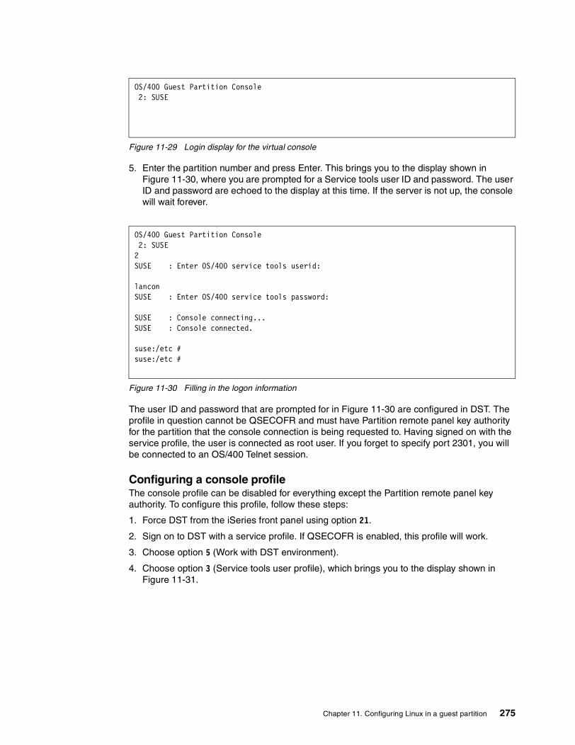
Figure 11-29 Login display for the virtual console
5. Enter the partition number and press Enter. This brings you to the display shown in Figure 11-30, where you are prompted for a Service tools user ID and password. The user ID and password are echoed to the display at this time. If the server is not up, the console will wait forever.
Figure 11-30 Filling in the logon information
The user ID and password that are prompted for in Figure 11-30 are configured in DST. The profile in question cannot be QSECOFR and must have Partition remote panel key authority for the partition that the console connection is being requested to. Having signed on with the service profile, the user is connected as root user. If you forget to specify port 2301, you will be connected to an OS/400 Telnet session.
Configuring a console profileThe console profile can be disabled for everything except the Partition remote panel key authority. To configure this profile, follow these steps:
1. Force DST from the iSeries front panel using option 21.
2. Sign on to DST with a service profile. If QSECOFR is enabled, this profile will work.
3. Choose option 5 (Work with DST environment).
4. Choose option 3 (Service tools user profile), which brings you to the display shown in Figure 11-31.
OS/400 Guest Partition Console 2: SUSE
OS/400 Guest Partition Console 2: SUSE 2 SUSE : Enter OS/400 service tools userid: lancon SUSE : Enter OS/400 service tools password: SUSE : Console connecting... SUSE : Console connected. suse:/etc # suse:/etc #
Chapter 11. Configuring Linux in a guest partition 275

Figure 11-31 Work with Server Tools User Profiles
5. Choose option 1 (Create). Then the Create Service Tools User Profile display (Figure 11-32) appears.
Figure 11-32 Create Service Tools User Profile
6. You can create a profile for just the function in question if so desired. The user ID and password are set here. If the user will manage non-hosted partitions, then you need to choose Yes to allow access before storage management recovery. Then press Enter, and the Change Service Tools User Privileges display (Figure 11-33) appears.
Figure 11-33 Change Service Tools User Privileges
Work with Service Tools User Profiles System: XXXXXXXXX Type option, press Enter. 1=Create 2=Change password 3=Delete 4=Display 5=Enable 6=Disable 7=Change privileges 8=Change description User Opt Profile Description Status Name1 Service user Enabled
Create Service Tools User Profile System: vvvvvvvvvvvvService Tools user profile name . . . . : ConsoleusrType chices, press enterPassword . . . . . . . . . . . . . . . .Allow profile access before storage management recovery . . . . . . . 1 1=Yes, 2=NoSet password to expire . . . . . . . . . . . . 2 1=Yes, 2=NoDescription. . . . . . . . . . . . . . . . . . . . . Console user
Change Service Tools User Privileges System: nnnnnnnnnnnnService tools user profile name . . . . . ConsoleusersType option, press Enter. 1=Revoke 2=GrantOption Functions Status None Revoked Disk Units - operations Revoked System partitions - operations Revoked System partitions - administration Revoked Partition remote panel key XXXXXXXX 000 Revoked 2 Partition remote panel key XXXXXXXX 001 Revoked
276 LPAR Configuration and Management: Working with iSeries Logical Partitions

7. Enable the user to access the remote console for partition 001. If they require access to other panels, there are more options for 002, 003, etc.
The only authority the console user needs is that defined above. As you can see, the other options are revoked by default.
Identifying console connectionsIt may be the case that you need to know who is accessing your virtual console or you want to terminate the console connections. You may also want to do this if you experience performance issues or when something seems to be hung. You can accomplish this by issuing the command from the OS/400 command line:
netstat *cnn
When reviewing the entries, you should find at least one entry for as-vcons as illustrated in Figure 11-34. If you choose F14 (Display port numbers), it should show a local port of 2301 in listening status. This is the daemon and does not need to be cancelled. Scroll down, and if there are connections to the console, there will be other entries for as-vcons with the remote port of 2301 and a local port of some random port number. Unlike the daemon entry, there will be an IP address displayed and the connection will appears as established. The later entries are the console connections and may be terminated at the discretion of the administrator. The daemon is shown in Figure 11-34.
Figure 11-34 Work with TCP/IP Connection Status
Scroll down to see the console connections (Figure 11-35) as described above.
Work with TCP/IP Connection Status System: SEATTLE Type options, press Enter. 3=Enable debug 4=End 5=Display details 6=Disable debug 8=Display jobs Remote Remote Local Opt Address Port Port Idle Time State * * ftp-con > 008:21:47 Listen * * telnet 000:14:55 Listen * * smtp 056:34:39 Listen * * snmp 005:29:25 *UDP * * 389 000:29:43 Listen * * drda 056:35:44 Listen * * ddm 056:35:44 Listen * * ddm-ssl 056:35:44 Listen * * as-svrmap 031:25:18 Listen * * lpd 056:35:38 Listen * * as-vcons 000:01:09 Listen * * as-sts 049:16:17 Listen More... F5=Refresh F11=Display byte counts F13=Sort by column F14=Display port numbers F22=Display entire field F24=More keys
Chapter 11. Configuring Linux in a guest partition 277

Figure 11-35 Established sessions to the ‘virtual’ console
Virtual LAN configurationAs mentioned previously, the virtual LAN is available to secondary partitions as well as guest partitions. However, it is the only means of communicating from a guest partition to an OS/400 partition. Data can be transferred between the two partitions in this manner, but it may be the only means of communicating to and from the server if directly attached LAN adapters were not allocated. It has been noted elsewhere that this is not a physical adapter or LAN connection. Literally, it is a virtual connection, meaning that it is really emulating an Ethernet LAN. This is not important to the user, since it configures exactly like a physical Ethernet. It is rated as Gigabit Ethernet and as many as 16 LANs can be configured.
For the most efficient configuration, you need to follow these steps:
1. Define an IP addressing scheme and route.
2. Enable the same port during partitioning for the guest partition and the partition to which it will communicate. We assume port 0 for a guest partition and the primary partition.
3. Configure OS/400. This means you need to create a line description and set up the appropriate interfaces and routes.
4. Configure Linux. This means you need to define an interface, veth0 in our example, and a default gateway. Interactively this is done by means of the ifconfig command and the route command from a Linux command line.
Enabling the port on the virtual LAN or LANsThe ports are enabled during the partitioning process as in the illustration for creating a guest partition. After the fact, you can do this by starting the System Service Tools (primary system) and selecting option 5 (Work with system partitions), followed by option 3 (Work with partition configuration), and then F10 (Work with virtual LAN configuration). Specify 1 for the preferred “port”, port 0 in this example.
Work with TCP/IP Connection Status System: SEATTLE Type options, press Enter. 3=Enable debug 4=End 5=Display details 6=Disable debug 8=Display jobs Remote Remote Local Opt Address Port Port Idle Time State * * as-tran > 079:39:18 Listen * * as-vrtp > 079:39:17 Listen 2039 telnet 000:04:52 Established 2465 telnet 000:03:18 Established 2527 as-sts 072:55:09 Established 2539 as-sts 072:55:07 Established 127.0.0.1 s-vcons 5099 000:03:18 Established 127.0.0.1 5099 as-vcons 000:03:18 Established Bottom F5=Refresh F11=Display byte counts F13=Sort by column F14=Display port numbers F22=Display entire field F24=More keys
278 LPAR Configuration and Management: Working with iSeries Logical Partitions

You need to do this for all partitions that will be on the same LAN. It is possible to configure multiple LANs – up to 16 per partition. In Figure 11-36, partition 0 is configured for ports 2 and 4, and partition 1 is configured for ports 0, 2, and 4, while partition 2 is only on LAN 0.
Figure 11-36 Work with Virtual LAN Configuration
Defining IP addressing scheme and routeThe virtual LAN is not a literal adapter or adapters, but rather a message passing utility that emulates a network. It must be treated as a LAN segment or segments and, as such, requires all of the same considerations that a TCP/IP network would. In a simple two-partition setup, which the following discussion assumes, there are two nodes on the network: the OS/400 node and the Linux node. These nodes need to be on the same network. When considering the addressing and routing scheme for the virtual LAN, it is important to define what communications are needed.
What will the virtual LAN be used for? You should address the following considerations:
� Strictly interpartition communication. This is the simplest possible scenario. However, by way of example, it may serve a purpose. The OS/400 and Linux must be on the same network, but the addressing scheme is really only significant within the particular OS/400 since there is no network access externally. We mention it as a situation that requires no subnetting. This setup could be used to FTP data to and from the Linux partition, but there would be no access to the network unless the Linux partition had a directly attached (Native) LAN adapter. A more complicated scenario in which this may be useful would be in that scenario when a Firewall is involved (Figure 11-37).
� The virtual network has non-registered “private addresses”. Generally speaking it would require a significant effort to reconfigure the routing scheme. Alternatively OS/400 NAT could be configured to the translate the non-registered address into the x.5.1.2 address. But this is not a very good solution at this time and is only effective for traffic outbound from Linux.
� The best solution for using the virtual LAN to pass traffic through the network card x.5.1.2 is to make the Linux interfaces be subnets of the network that X.5.1.2 is on and allow the OS/400 to proxy ARP for the partitions, that is to act as a router for virtual network. This
Work with Virtual LAN Configuration System: SEATTLE Type options, press Enter. 2=Change Par -------------------Virtual LAN Identifiers------------------- Opt ID Name 0 1 2 3 4 5 6 7 8 9 10 11 12 13 14 15 0 PRIMARY 1 . 1 . . . . . . . . . . . 1 AS05B 1 . 1 . 1 . . . . . . . . . 2 SUSE 1 . . . . . . . . . . . . . '1' Indicates LAN in use. '.' Indicates LAN not in use. F3=Exit F9=Show all partitions F11=Display communication options F12=Cancel
Note: This discussion assumes that you have a reasonable understanding of subnet masking and networking. If you need some background, you can review subnetting and TCP/IP networking in TCP/IP Tutorial and Technical Overview, GG24-3376.
Chapter 11. Configuring Linux in a guest partition 279

means that a minimum of four contiguous addresses starting on a multiple of four are required for one guest partition. The four addresses provide two usable addresses. The highest address of the block is reserved as a broadcast address for the subnetwork, and the lowest address is the network address itself, which defines this as a unique subnetwork of the x.5.1.0 network. If there were more partitions communicating across the same virtual LAN, the block of addresses would need to be larger. If you have two to five secondary partitions, you would need a block of eight contiguous addresses starting on a multiple of eight, and six to 13 secondary partitions would require a block 16 contiguous addresses starting on a multiple of 16. The requirement is not unique to the OS/400, but it is a function of TCP/IP networking. This is the only option that is discussed in this redbook.
� The remaining option is to use a “native” direct attached adapter in each Linux partition and configure Linux to do the communication using the virtual LAN only for passing messages between the OS/400 partition and the Linux partitions. In this example, the veth0 interface (the virtual LAN interface 0 in Linux) could remain a non-registered address, but the eth0 interface (the native adapter interface) would either need to be translated via NAT or a public address.
The network to be configured is shown in Figure 11-37. The external network segment connected to OS/400 is X.5.1.0, subnetted as 255.255.255.0, which means that there are potentially 256 minus 2 (or 254) usable host addresses. The virtual LAN is the equivalent of a separate LAN segment in this configuration. That is it appears to the machine as if it were a separate Ethernet network. In this context, the OS/400 is serving as a router between two separate networks. TCP/IP is routed from hop to hop. This means that the virtual LAN must be a subnetwork of the x.5.1.0 network. In turn, this means that a subset of the 254 usable addresses must be converted to network bits using the subnet mask to limit the number of hosts and expand the number of networks available. The 255.255.255.252 masks off all hosts bits except two. Two bits means that there are four possible combination of bits available to use as hosts – 00, 01, 10, and 11. However, TCP/IP mandates that all zeros are reserved for the network address and all ones are reserved for the broadcast address. Therefore, out of the four combinations, only two are usable. The subnet mask we used (255.255.255.252) defines each subnet as having four possible hosts, but only two usable ones. This explains the necessity of blocks of four addresses and the masking mechanism dictates that the network address be a multiple of four (in order to subnet to a 00 address).
Note: The Xs in the addresses are not a valid IP notation. However, since we are using only the last two bits of the last octet, the numbers that would have been there are insignificant for purposes of this discussion. In any real configuration, they would need to be a valid decimal notation.
280 LPAR Configuration and Management: Working with iSeries Logical Partitions

Figure 11-37 Example network
Configuring OS/400 On the OS/400 side of the virtual LAN, the following configuration needs to be done to communicate from the network through the hosting partition LAN adapter over the virtual LAN to the Linux partition and from the Linux partition to the network across the same route. This assumes that the OS/400 is already configured for the x.5.1.2 network, the subnet mask is 255.255.255.0, and that the interface and line description are functional.
1. Create an Ethernet line description using the CRTLINETH command.2. Create an interface for the OS/400 side of the virtual LAN.3. Create a route from the virtual LAN interface to the OS/400 network.4. Turn on IP datagram forwarding.
Creating an Ethernet line description for the virtual LANTo create an Ethernet line description for the virtual LAN, you need to use the CRTLINETH command. The name of the line description can be anything, but we call it Veth to remain consistent. The virtual resource is actually defined to the OS/400 as a type of 268C and can be viewed by issuing the command WRKHDWRSC *CMN or using the service tools.
Figure 11-38 shows four virtual Ethernet ports. The resource required for the line description is CMNXX. If 268C does not appear, the configuration of the virtual LAN may have been omitted during the creation of the partition.
Part 1 - OS/400 Part 2 - Linux
x.x.x.97
OS/400
Virtual LAN
Linux x.x.x.98
Real Network Adapter
Virtual Networkx.x.x.96x.x.x.99
Network Addressx.x.x.96SUBNET 255.255.255.252
Real Networkx.5.1.2255.255.255.0
4Addresses
X.5.1.2
Chapter 11. Configuring Linux in a guest partition 281

Figure 11-38 Displaying the virtual LAN resource
The command and pertinent parameters are:
CRTLINETH LIND(VETH) RSRCNAME(CMN05) LINESPEED(1G) DUPLEX(*FULL)
Another parameter that may be of interest and might be experimented with as a performance boost is the maximum frame size, which can be 8996, as opposed to the traditional 1492 bytes for Ethernet. Changing to 8996 bytes improved the throughput significantly for the data transfer across the virtual LAN.
Creating an interface for the virtual LANThe interface must be created with an IP address that is a subnet of the OS/400 network. We simply say the interface is x.x.x.97 with a subnet mask of 255.255.255.252, which would allow us two usable addresses. Use the CFGTCP command, option 1 (Work with TCP/IP interface), and then option 1 again. A display appears like the example in Figure 11-39.
The parameters shown in bold are significant. In particular, Associated local interface needs to be the address of the OS/400 adapter to be routed to.
Work with Communication Resources System: AS05B Type options, press Enter. 5=Work with configuration descriptions 7=Display resource detail Opt Resource Type Status Text CMB01 284B Operational Combined function IOP LIN01 2744 Operational LAN Adapter CMN01 2744 Operational Token-Ring Port LIN03 2744 Operational LAN Adapter CMN04 2744 Operational Token-Ring Port CC01 268C Operational Comm Processor LIN02 268C Operational LAN Adapter CMN05 268C Operational Ethernet Port CMN02 268C Operational Ethernet Port CMN03 268C Operational Ethernet Port Bottom F3=Exit F5=Refresh F6=Print F12=Cancel
282 LPAR Configuration and Management: Working with iSeries Logical Partitions

Figure 11-39 Interface for the virtual LAN
Creating a route to the OS/400 adapter from the virtual LAN subnetworkUse the CFGTCP command and select option 2. The Add TCP/IP Route (Figure 11-40) appears. This is a route from the x.x.x.96 network to the OS/400 adapter.
Figure 11-40 Adding a route between the internal network and host adapter
Add TCP/IP Interface (ADDTCPIFC) Type choices, press Enter. Internet address . . . . . . . . . > x.x.x.97 Line description . . . . . . . . . veth Name, *LOOPBACK... Subnet mask . . . . . . . . . . 255.255.255.252 Associated local interface . . . . . x.5.1.2 Type of service . . . . . . . . . *NORMAL *MINDELAY, *MAXTHRPUT... Maximum transmission unit . . . . . . . *LIND 576-16388, *LIND Autostart. . . . . . . . . . . . . . . .*YES *YES, *NO PVC logical channel identifier 001-FFF + for more values X.25 idle circuit timeout . . . . . . . . . 60 1-600 X.25 maximum virtual circuits . . . . . 64 0-64 X.25 DDN interface . . . . . . . . . *NO *YES, *NO TRLAN bit sequencing . . . . . . . . *MSB *MSB, *LSB Bottom F3=Exit F4=Prompt F5=Refresh F12=Cancel F13=How to use this display F24=More keys
Add TCP/IP Route (ADDTCPRTE) Type choices, press Enter. Route destination . . . . . . . . . . . .> x.x.x.96 Subnet mask . . . . . . . . . . . . . . . .> 255.255.255.252 Type of service . . . . . . . . . . . . . . *NORMAL *MINDELAY, *MAXTHRPUT... Next hop . . . . . . . . . . . . . . . . . . . . > x.5.1.2 Preferred binding interface . . . . . *NONE Maximum transmission unit . . . . . *IFC 576-16388, *IFC Route metric . . . . . . . . . . . . . . . . 1 1-16 Route redistribution . . . . . . . . . . *NO *NO, *YES Duplicate route priority . . . . . . . . 5 1-10 Bottom F3=Exit F4=Prompt F5=Refresh F12=Cancel F13=How to use this display F24=More keys
Chapter 11. Configuring Linux in a guest partition 283

Turning on IP datagram forwarding on OS/400You can turn on IP forwarding to enable the OS/400 to route the packets from the virtual LAN to the network adapter. This requires changing the TCP/IP attributes. The command is CHGTCPA. The significant parameter is IP datagram forwarding (Figure 11-41). Scrolling to the next page, we also recommend you change Log Protocol Errors to yes.
Figure 11-41 Enabling IP datagram forwarding
Active TCP/IP interface Type option 9 next to x.x.x.97 to active TCP/IP interface as shown in Figure 11-42.
Figure 11-42 Work with TCP/IP Interface Status
Change TCP/IP Attributes (CHGTCPA) Type choices, press Enter. TCP keep alive . . . . . . . . . 120 1-40320, *SAME, *DFT TCP urgent pointer . . . . . . . *BSD *SAME, *BSD, *RFC TCP receive buffer size . . . . 8192 512-8388608, *SAME, *DFT TCP send buffer size . . . . . . 8192 512-8388608, *SAME, *DFT TCP R1 retransmission count . . 3 1-15, *SAME, *DFT TCP R2 retransmission count . . 16 2-16, *SAME, *DFT TCP closed timewait timeout . . 120 0-14400, *SAME, *DFT UDP checksum . . . . . . . . . . *YES *SAME, *YES, *NO Path MTU discovery: Enablement . . . . . . . . . . *YES *SAME, *DFT, *NO, *YES Interval . . . . . . . . . . . 10 5-40320, *ONCE IP datagram forwarding . . *YES *SAME, *YES, *NO IP source routing . . . . . . . *YES *SAME, *YES, *NO IP reassembly time-out . . . . . 10 5-120, *SAME, *DFT IP time to live . . . . . . . . 64 1-255, *SAME, *DFT IP QoS enablement . . . . . . . *NO *SAME, *TOS, *YES, *NO More... F3=Exit F4=Prompt F5=Refresh F12=Cancel F13=How to use this display F24=More keys
Work with TCP/IP Interface Status System: AS05B Type options, press Enter. 5=Display details 8=Display associated routes 9=Start 10=End 12=Work with configuration status 14=Display multicast groups Internet Network Line Interface Opt Address Address Description Status x.x.x.2 x.x.x.0 TRNLINE Active x.x.x.97 x.x.x.96 VETH Active 127.0.0.1 127.0.0.0 *LOOPBACK Active Bottom F3=Exit F4=Prompt F5=Refresh F11=Display line information F12=Cancel F13=Sort by column F24=More keys
284 LPAR Configuration and Management: Working with iSeries Logical Partitions

Configuring Linux for the virtual LANThe individual commands to configure the Linux server are issued manually from the virtual console to test the configuration are:
ifconfig veth0 x.x.x.98 netmask 255.255.255.252 uproute add -net x.x.x.96 netmask 255.255.255.252 gw x.x.x.97route add default gw x.x.x.97
As listed the commands are good for the life of the session. You must add these to the appropriate script file so that the configuration is restarted at every boot. The files vary by distribution but are usually /etc/rc.local or /etc/rc.config.
At this point, you should be able to ping from Linux x.x.x.98 to x.x.x.97 across the virtual LAN and from x.x.x.98 to x.5.1.2 or to the network beyond. In fact, you should now be able to Telnet into the server from the network, run X Windows, and do other Linux tasks with the right client software.
For assistance with the ping, ipconfig, and route commands or most other Linux commands that are run from a command line, use the prefix man, for example man ping, man ipconfig, and man route.
Using virtual CD-ROMThe virtual CD provides access to the hosting OS/400 partition CD drive. There is a parameter on the NWSD that can restrict Linux from accessing CD drives, but by default, it can see all CD drives on the hosting partition.
With devfs support, these devices show up under the /dev/cdroms directory, for example /dev/cdroms/cdrom0. To use a CD-ROM, it must be mounted as well. For example, to mount it under the /mnt/cdrom directory, use:
mount /dev/cdroms/cdrom0 /mnt/cdrom
There is a parameter in the NWSD that can restrict the optical or tape devices that can be used by Linux. See the Figure 11-43 and Figure 11-44. When running CHGNWSD from the OS/400 command line, you see the display shown in Figure 11-43, which shows the options for restricting devices. The help text for this prompt can assist in clarifying what the parameters are about.
Note: When you ping in Linux, the command needs to have a count set, or it will ping forever, until you press Ctrl-C. It should be set to:
ping -c 4 x.x.x.97
Chapter 11. Configuring Linux in a guest partition 285
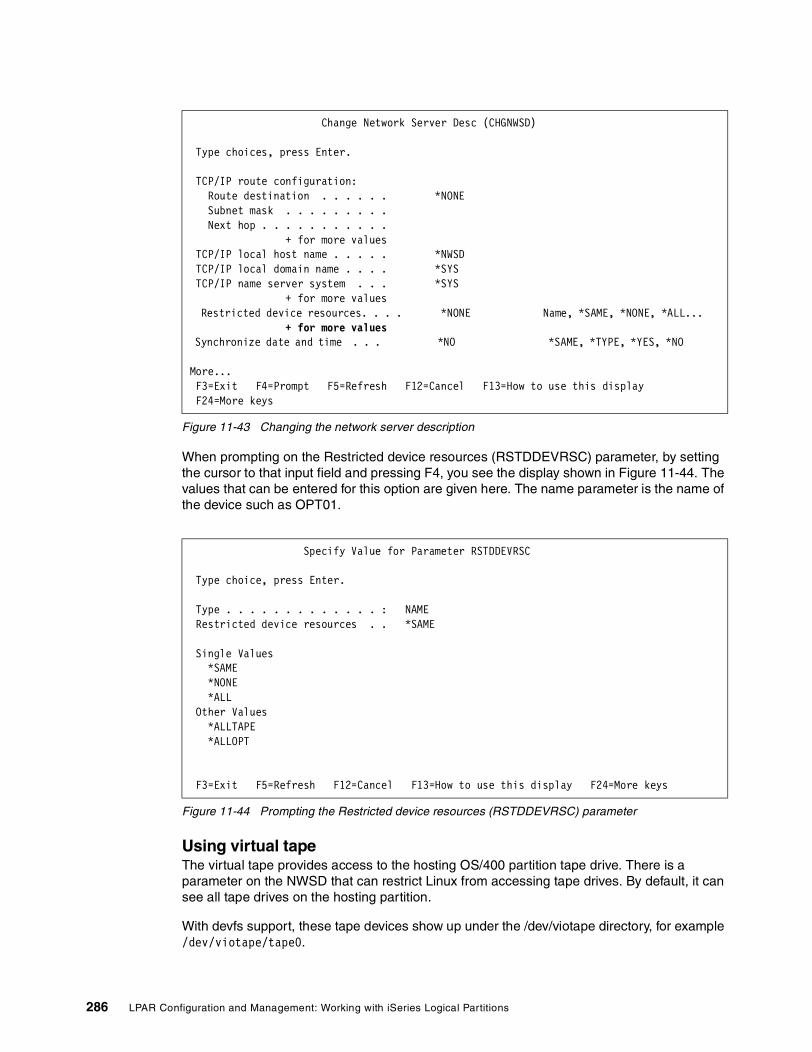
Figure 11-43 Changing the network server description
When prompting on the Restricted device resources (RSTDDEVRSC) parameter, by setting the cursor to that input field and pressing F4, you see the display shown in Figure 11-44. The values that can be entered for this option are given here. The name parameter is the name of the device such as OPT01.
Figure 11-44 Prompting the Restricted device resources (RSTDDEVRSC) parameter
Using virtual tapeThe virtual tape provides access to the hosting OS/400 partition tape drive. There is a parameter on the NWSD that can restrict Linux from accessing tape drives. By default, it can see all tape drives on the hosting partition.
With devfs support, these tape devices show up under the /dev/viotape directory, for example /dev/viotape/tape0.
Change Network Server Desc (CHGNWSD) Type choices, press Enter. TCP/IP route configuration: Route destination . . . . . . *NONE Subnet mask . . . . . . . . . Next hop . . . . . . . . . . . + for more values TCP/IP local host name . . . . . *NWSD TCP/IP local domain name . . . . *SYS TCP/IP name server system . . . *SYS + for more values Restricted device resources. . . . *NONE Name, *SAME, *NONE, *ALL... + for more values Synchronize date and time . . . *NO *SAME, *TYPE, *YES, *NO More... F3=Exit F4=Prompt F5=Refresh F12=Cancel F13=How to use this display F24=More keys
Specify Value for Parameter RSTDDEVRSC Type choice, press Enter. Type . . . . . . . . . . . . . : NAME Restricted device resources . . *SAME Single Values *SAME *NONE *ALL Other Values *ALLTAPE *ALLOPT F3=Exit F5=Refresh F12=Cancel F13=How to use this display F24=More keys
286 LPAR Configuration and Management: Working with iSeries Logical Partitions

11.3.3 Native I/O (hosted or non-hosted partitions)Fundamentally, the procedure is the same to create a non-hosted or hosted partition. By definition, a non-hosted partition does not use virtual resources and, therefore, does not require a hosting partition to be defined when the partition is created. The major configuration task is removing resources from a partition and allocating them to a Linux partition. The fact that direct attached IOAs are used is not unique to a non-hosted partition. Therefore, the following considerations are true also when allocating native I/O to use in a hosted partition.
Allocating resourcesAdapters in Linux plug into the bus and communicate through drivers to the software, unlike the iSeries, where adapters are connected to an IOP (input-output processor). The IOP provides the ability to offload tasks from the system processor to the IOP – tasks such as identifying and communicating with the hardware. This is one of many features on the iSeries that contribute to its stability, reliability, and ease of use. Linux does not know about IOPs. Therefore, it is necessary to emulate the PCI bus structure that Linux knows about to allow Linux to operate as it would in other environments. The result is what is known as “direct attach” adapters. These are adapters without an IOP attached. Much of the IBM-supplied code is the extensions to the kernel to present the correct interface to Linux.
With the new PCI technology, there are new rules for configuring the various features. There is more flexibility in the placement of IOPs and IOAs, but conversely it is more important to be aware of the rules associated with configuration. There are “hard” rules that are enforced by the configurator and “soft rules” that qualify various configurations. There are some specific rules with regard to the placement and management of the direct attached cards. There are specific issues with card placements on the first bus of the CEC. This is particularly important to note with regard to the Model 270.
Until the card is removed from the iSeries’ control, it is governed by the normal rules for IOPs and IOAs in that box. When it is allocated to Linux, it will be ignored by the iSeries and belong to Linux as a directly attached IOA.
Adapter statusAdapters that are not attached to an IOP cannot be identified by the iSeries server, although it will recognize the fact that hardware is installed in the slot. Therefore, we must preface this discussion by briefly noting how the system denotes empty slots as opposed to those that it cannot identify and how it tags those adapters that belong to a Linux partition.
There are three states with which we are primarily concerned:
� Empty position: The slot is empty. A slot that is not physically plugged is seen in the service tools as an empty position.
� Occupied position: A slot that has a card in it, but is not attached to an IOP, is seen as an occupied position signifying that the system knows that there is a card there, but cannot identify it. This might be due to the fact that there is physically no IOP installed or because it was removed from the IOP. In our case, it would be because it was either removed from the IOP in preparation for adding it to the Linux partition or because it was removed from the Linux partition presumably to return it to OS/400. In some scenarios, it may be the result of “stale” data that has not yet been cleaned up.
� Generic adapter: Generic adapter is the designation for an adapter that has been added to a Linux partition. It has type of 274D.
Figure 11-45 shows adapters in “occupied position” and an adapter in “generic adapter” status.
Chapter 11. Configuring Linux in a guest partition 287

Figure 11-45 Adapter Status: Occupied Position and Generic Adapter
To access this screen, follow these steps:
1. Go into SST (STRSST).2. Choose 5 (Work with system partitions).3. Choose 1 (Display partition information).4. Type 3 (Display allocated I/O resources).
Adding and removing adaptersBefore any resources can be removed from a partition and added to a Linux partition, the bus on which the resources are located must be shared. The guest partition cannot own a shared bus. A shared bus is the opposite of a dedicated bus. A dedicated bus means that all the resources shared on that bus are dedicated to the partition that owns the bus. A bus cannot have its ownership changed while other partitions are using the resources. To change bus ownership, follow these steps:
1. Go into SST (STRSST).
2. Choose 5 (Work with system partitions).
3. Choose 3 (Work with partition configuration) and a display like the one in Figure 11-46 appears.
4. Type 5 before the partitions from which you want to change the bus ownership. Then press Enter.
Display Allocated I/O Resources System: SEATTLE System partition(s) to display . . . . *ALL *ALL, 0-2 Level of detail to display . . . . . . *ALL *ALL, *BUS, *IOP, *IOA, *DEV Par Serial Part ID Description Type-Model Number Number Occupied Position Occupied Position 1 LINUX1 Partition 9406-270 10-509BM System Bus 23 283B- 38-0293021 04N4723 Generic Adapter 274D- System Bus 24 283B- 38-0293021 04N4723 2 LINUX2 Partition 9406-270 10-509BM * Indicates load source. F3=Exit F5=Refresh F6=Print F9=Toggle empty pos F10=Display logical address F11=Display partition status F12=Cancel
288 LPAR Configuration and Management: Working with iSeries Logical Partitions

Figure 11-46 Working with the partition configuration to change bus ownership
5. Type 1 or 2 before the bus whose status you want to change as shown in Figure 11-47.
Figure 11-47 Changing bus ownership
Work with Partition Configuration System: SEATTLE Type option, press Enter. 1=Change partition name 2=Change partition processing resources 3=Add I/O resources 4=Remove I/O resources 5=Change bus ownership type 6=Select load source resource Partition Option Identifier Name 0 PRIMARY 1 LINUX1 2 LINUX2 3 LINUX3 F3=Exit F5=Refresh F9=Work with shared processor pool F10=Work with Virtual LAN configuration F11=Work with partition status F12=Cancel F23=More options
Change Bus Ownership Type System: SEATTLE Level of detail to display . . . . . . *ALL *ALL, *BUS, *IOP, *IOA, *DEV Partition identifier . . . . . . . . . . . . . : 0 Partition name . . . . . . . . . . . . . . . . : PRIMARY Type options, press Enter. 1=Own bus dedicated 2=Own bus shared I/O Resource Owning Ownership Opt Description Type-Model Par ID Type 2 System Bus 1 282D- 0 2 Combined Function IOP *< 284C-001 0 1 Workstation IOA 2746-001 0 1 Display Station 3487-0HC 0 1 Communications IOA 2771-001 0 1 Communications Port 2771-001 0 1 Communications Port 2771-001 0 1 Communications IOA 2744-001 0 1 Communications Port 2744-001 0 1 More... F3=Exit F9=Toggle empty pos F10=Display serial/part numbers F12=Cancel
Chapter 11. Configuring Linux in a guest partition 289

The process of allocating any of the adapters is essentially the same for any type of adapter, but there is a particular concern with allocating DASD. If the DASDs are configured, the system will allow you to remove them, although it gives you warning messages. If you continue, there will be a problem that will require an IPL to escape from it. If you will allocate DASDs to a Linux partition, verify that they are unconfigured. It they are not, you need to IPL to DST and remove them from the ASP.
There are two ways to remove and assign adapters:
� Using the LPAR configuration manager: This is the preferred method, because it cleans up stale configuration data. We strongly recommend that you use this method for everything that needs to be done. There are two exceptions when it is necessary to use concurrent maintenance, which is discussed further under “Concurrent maintenance” on page 300. The IOP must be removed to add the IOA, which may not be practical where an IOA is owned by a combined function IOP or a multifunction IOP that has other devices including DASD attached to it. For newly installed systems or systems acquiring and configuring new hardware, this is not a problem. The steps to remove an adapter using the Work with system partitions option are outlined here:
a. Remove the IOP from the OS/400 partition. Start SST (STRSST) and select option 5 (Work with system partitions).
b. Select option 3 (Work with partition configuration). A display like the example in Figure 11-48 appears.
Figure 11-48 Work with Partition Configuration
Work with Partition Configuration System: SEATTLE Type option, press Enter. 1=Change partition name 2=Change partition processing resources 3=Add I/O resources 4=Remove I/O resources 5=Change bus ownership type 6=Select load source resource Partition Option Identifier Name 4 0 PRIMARY 1 LINUX1 2 LINUX2 3 LINUX3 F3=Exit F5=Refresh F9=Work with shared processor pool F10=Work with Virtual LAN configuration F11=Work with partition status F12=Cancel F23=More options
290 LPAR Configuration and Management: Working with iSeries Logical Partitions

c. Select the partition that you want to remove resources from and type 4 in front of it. The display in Figure 11-49 appears.
Figure 11-49 Removing adapters
Remove I/O Resources System: SEATTLE Level of detail to display . . . . . . *ALL *ALL, *BUS, *IOP, *IOA, *DEV Partition identifier . . . . . . . . . . . . . : 0 Partition name . . . . . . . . . . . . . . . . : PRIMARY Type options, press Enter. 1=Remove 2=Remove and clear hardware resource(s) I/O Resource Serial Part Opt Description Type-Model Number Number System Bus 1 282D- E8-0261078 24L1460 2 Combined Function IOP *< 284C-001 E8-0261078 24L1460 Workstation IOA 2746-001 10-0244401 0000021H5497 Display Station 3487-0HC 00-******* Communications IOA 2771-001 10-0257321 0000021P4151 Communications Port 2771-001 10-0257321 0000021P4151 Communications Port 2771-001 10-0257321 0000021P4151 Communications IOA 2744-001 10-61036 0000023L4288
More... * Indicates load source. F3=Exit F9=Toggle empty pos F10=Display logical address F12=Cancel
Chapter 11. Configuring Linux in a guest partition 291

d. Find the IOP that you want to remove and:
• Use 1 if you need to return the resource to the primary or hosting partition if a tape or CD-ROM is being shared between partitions, for example.
• Use option 2 if you want remove the resource permanently and delete the resource description.
The display in Figure 11-50 confirms your choice.
Figure 11-50 Confirming the removal of IOP
Confirm Remove I/O Resources System: SEATTLE Press Enter to confirm your choice to remove the following I/O resources from this partition. Removals can only be made at a bus or I/O processor level. Press F12 to return to change your choice. Partition identifier . . . . . . . . . . . . . : 0 Partition name . . . . . . . . . . . . . . . . : PRIMARY I/O Resource Serial Part Description Type-Model Number Number Combined Function IOP 2843-001 10-0271195 0000004N5095 Workstation IOA 2746-001 10-9265123 0000021H5497 Communications IOA 2744-001 10-0167047 0000023L4288 Communications Port 2744-001 10-0167047 0000023L4288 Multiple Function IOA 2748-001 10-0145071 0000004N2255 Disk Unit 6718-050 68-613E2 09L3932 Disk Unit 6718-050 68-6194D 09L3932 Disk Unit 6718-050 68-664D5 09L3932
More... * Indicates load source. F10=Display logical address F12=Cancel
292 LPAR Configuration and Management: Working with iSeries Logical Partitions

e. If there are resources attached the multi-function IOP that are active, you receive a warning that allows you to cancel and take care of the busy resource. Otherwise, the display returns a message notifying you that the resource was successfully removed (Figure 11-51).
Figure 11-51 Notification of successful removal of adapter
Remove I/O Resources System: SEATTLE Level of detail to display . . . . . . *ALL *ALL, *BUS, *IOP, *IOA, *DEV Partition identifier . . . . . . . . . . . . . : 0 Partition name . . . . . . . . . . . . . . . . : PRIMARY Type options, press Enter. 1=Remove 2=Remove and clear hardware resource(s) I/O Resource Serial Part Opt Description Type-Model Number Number System Bus 1 282D- E8-0261078 24L1460 Combined Function IOP *< 284C-001 E8-0261078 24L1460 Workstation IOA 2746-001 10-0244401 0000021H5497 Display Station 3487-0HC 00-******* Communications IOA 2771-001 10-0257321 0000021P4151 Communications Port 2771-001 10-0257321 0000021P4151 Communications Port 2771-001 10-0257321 0000021P4151 Communications IOA 2744-001 10-61036 0000023L4288 More... * Indicates load source. F3=Exit F9=Toggle empty pos F10=Display logical address F12=Cancel Remove I/O resource(s) was successful.
Chapter 11. Configuring Linux in a guest partition 293

f. When the IOP is removed, return to the Work with Partition Configuration display (Figure 11-52) and type 3 in front of the partition to which you want to add the resource.
Figure 11-52 Adding I/O resources to the Linux partition
Work with Partition Configuration System: SEATTLE Type option, press Enter. 1=Change partition name 2=Change partition processing resources 3=Add I/O resources 4=Remove I/O resources 5=Change bus ownership type 6=Select load source resource Partition Option Identifier Name 0 PRIMARY 1 LINUX1 2 LINUX2 3 3 LINUX3 F3=Exit F5=Refresh F9=Work with shared processor pool F10=Work with Virtual LAN configuration F11=Work with partition status F12=Cancel F23=More options
294 LPAR Configuration and Management: Working with iSeries Logical Partitions

g. If the bus is not shared, you need to use option 3 (Use bus shared) on the bus and option 1 (Own dedicated) on the IOA. Otherwise, the only option required is the option to dedicate the adapter. See Figure 11-53.
Figure 11-53 Adding an adapter and sharing the bus
Add I/O Resources System: SEATTLE Level of detail to display . . . . . . *ALL *ALL, *BUS, *IOP, *IOA, *DEV Partition identifier . . . . . . . . . . . . . : 3 Partition name . . . . . . . . . . . . . . . . : LINUX3 Type options, press Enter. 1=Own dedicated 2=Own bus shared 3=Use bus shared I/O Resource Serial Part Opt Description Type-Model Number Number System Bus 1 282D- E8-0261078 24L1460 3 System Bus 2 282D- E8-0261078 24L1460 Combined Function IOP 2843-001 10-0271195 0000004N5095 Workstation IOA 2746-001 10-9265123 0000021H5497 Communications IOA 2744-001 10-0167047 0000023L4288 Communications Port 2744-001 10-0167047 0000023L4288 Communications IOA 2838-001 10-0264282 0000021H5460 Communications Port 2838-001 10-0264282 0000021H5460 1 Multiple Function IOA 2748-001 10-0145071 0000004N2255 More... F3=Exit F9=Toggle empty pos F10=Display logical address F12=Cancel
Chapter 11. Configuring Linux in a guest partition 295

h. The next display (Figure 11-54) confirms that you made the right selection.
Figure 11-54 Confirming selection of resources
Confirm Add I/O Resources System: SEATTLE Press Enter to confirm your choice to add the following I/O resources to this partition. Press F12 to return to change your choice. Partition identifier . . . . . . . . . . . . . : 3 Partition name . . . . . . . . . . . . . . . . : LINUX3 I/O Resource Serial Part Opt Description Type-Model Number Number 3 System Bus 2 282D- E8-0261078 24L1460 1 Multiple Function IOA 2748-001 10-0145071 0000004N2255 1 Disk Unit 6718-050 68-613E2 09L3932 1 Disk Unit 6718-050 68-6194D 09L3932 1 Disk Unit 6718-050 68-664D5 09L3932 1 Disk Unit 6718-050 68-46776 09L3932 1 Device Services 283F-001 38-02299 0000004N2472 1 Disk Unit 6718-050 68-62318 09L3932 1 Disk Unit 6718-050 68-6128C 09L3932 F10=Display logical address F12=Cancel
296 LPAR Configuration and Management: Working with iSeries Logical Partitions

i. You receive a message that the resource was successfully added. You should also see “Generic Adapter” on the partition that you were adding it to (see Figure 11-55).
Figure 11-55 Display Allocated I/O Resources
Display Allocated I/O Resources System: SEATTLE System partition(s) to display . . . . *ALL *ALL, 0-3 Level of detail to display . . . . . . *ALL *ALL, *BUS, *IOP, *IOA, *DEV Par Serial Part ID Description Type-Model Number Number 1 LINUX1 Partition 9406-820 10-5310M System Bus 1 282D- E8-0261078 24L1460 System Bus 2 282D- E8-0261078 24L1460 2 LINUX2 Partition 9406-820 10-5310M System Bus 2 282D- E8-0261078 24L1460 3 LINUX3 Partition 9406-820 10-5310M System Bus 1 282D- E8-0261078 24L1460 System Bus 2 282D- E8-0261078 24L1460 Generic Adapter 274D- Bottom * Indicates load source. F3=Exit F5=Refresh F6=Print F9=Toggle empty pos F10=Display logical address F11=Display partition status F12=Cancel
Chapter 11. Configuring Linux in a guest partition 297

j. It is sometimes confusing as to whether the adapter is the correct one and whether what was assigned was actually correct. A very useful function in LPAR configuration display is option 5 (Display system I/O resources). The F10 key toggles to the logical address as shown in Figure 11-56.
Figure 11-56 F10 toggle to logical address
Display System I/O Resources System: SEATTLE Level of detail to display . . . . . . *IOA *ALL, *BUS, *IOP, *IOA, *DEV I/O Resource Description Type-Model Logical Address System Bus 1 282D- 2/ 1/ / - / / / / / / Combined Function IOP *< 284C-001 2/ 1/0/ 16- / / / / / / Workstation IOA 2746-001 2/ 1/0/ 16-3/ /14/ 1/ / / Communications IOA 2771-001 2/ 1/0/ 16-1/ /14/ 3/ / / Communications IOA 2744-001 2/ 1/0/ 16-1/ /14/ 6/ / / Communications IOA 2838-001 2/ 1/0/ 16-1/ /14/ 7/ / / Multiple Function IOA 2748-001 2/ 1/0/ 16-2/ 2/ / / / / System Bus 2 282D- 2/ 2/ / - / / / / / / Combined Function IOP 2843-001 2/ 2/0/ 16- / / / / / / Workstation IOA 2746-001 2/ 2/0/ 16-3/ /14/ 1/ / / Communications IOA 2744-001 2/ 2/0/ 16-1/ /14/ 2/ / / Communications IOA 2838-001 2/ 2/0/ 16-1/ /14/ 6/ / / Generic Adapter 274D- 2/ 2/0/ 21- / / / / / / System Bus 25 283B- 2/ 25/ / - / / / / / / More... F3=Exit F5=Refresh F6=Print F9=Toggle empty pos F10=Display physical address F11=Display partition status F12=Cancel
298 LPAR Configuration and Management: Working with iSeries Logical Partitions

k. If you toggle it again, it displays the physical address. From the card slot address, you can verify that the IOA you added was, in fact, the correct one. The logical address could confirm this also if you checked it in advance. See Figure 11-57.
Figure 11-57 Physical address
Display System I/O Resources System: SEATTLE Level of detail to display . . . . . . *IOA *ALL, *BUS, *IOP, *IOA, *DEV I/O Resource -Physical Address- Description Type-Model Frame ID Card Pos System Bus 1 282D- 1 Combined Function IOP *< 284C-001 1 MB1 Workstation IOA 2746-001 1 C06 Communications IOA 2771-001 1 C04 Communications IOA 2744-001 1 C02 Communications IOA 2838-001 1 C01 Multiple Function IOA 2748-001 1 C05 System Bus 2 282D- 1 Combined Function IOP 2843-001 1 C12 Workstation IOA 2746-001 1 C11 Communications IOA 2744-001 1 C10 Communications IOA 2838-001 1 C07 Generic Adapter 274D- 1 C08 System Bus 25 283B- More... F3=Exit F5=Refresh F6=Print F9=Toggle empty pos F10=Display vendor information F11=Display partition status F12=Cancel
Chapter 11. Configuring Linux in a guest partition 299

l. Toggling it yet again displays the vendor information. We skip this here. But if you toggle it yet again, it shows status and ownership information, and finally it displays the using partitions. This sequence of the screen is very useful in sorting out partition resource information. See Figure 11-58.
Figure 11-58 Verifying the resource status
m. Return to the Work with Partition Configuration display and add back the IOP to the OS/400 partition. Any additional adapters that were attached to it will be returned with it.
� Concurrent maintenance: This option is accessed by way of the Hardware Service Manager and is not intended for casual use. There are two specific instances when it is necessary to use this. But if you are not very conversant with the options or are not comfortable using them, we recommend that you contact your customer engineer.
The specific instances that might be encountered are:
– You want to remove and IOA and return it to the OS/400 partition.– You have a multi-function IOP that has an adapter that you want to remove without
removing the IOP.
This would normally occur when a DASD IOA is attached to the IOP. If the DASD is configured, it is necessary to IPL to DST and unconfigure them. However, if you had a communications adapter that you wanted to remove, this would be the way. We discourage this method because it was not intended for casual use. In some cases, it can result in confused statuses of devices that typically aren’t fatal, but can result wasting a lot of time in trying to reconcile these. There is almost no reason to do this on a new system or if you are acquiring new resources for a Linux partition. If you are redistributing resources, it may be necessary. Consider consulting your customer engineer if you need to use this approach. The following displays take you through the procedure:
a. Start a service tool (STRSST) and choose option 7 (Hardware service manager) as shown in Figure 11-59.
Display System I/O Resources System: SEATTLE Level of detail to display . . . . . . *IOA *ALL, *BUS, *IOP, *IOA, *DEV I/O Resource Owning Ownership Description Type-Model Status Par ID Type System Bus 1 282D- Available 0 2 Combined Function IOP *< 284C-001 Available 0 1 Workstation IOA 2746-001 0 1 Communications IOA 2771-001 0 1 Communications IOA 2744-001 0 1 Communications IOA 2838-001 0 1 Multiple Function IOA 2748-001 0 1 System Bus 2 282D- Available 0 2 Combined Function IOP 2843-001 Available Workstation IOA 2746-001 Communications IOA 2838-001 Generic Adapter 274D- Available 3 1 System Bus 25 283B- Other: 0301 More... F3=Exit F5=Refresh F6=Print F9=Toggle empty pos F10=Display using partitions F11=Display partition status F12=Cancel
300 LPAR Configuration and Management: Working with iSeries Logical Partitions

Figure 11-59 Choosing the HSM to use concurrent maintenance
b. The Hardware Service Manager display appears as shown in Figure 11-60. Select option 1 (Packaging hardware resources (systems, frames, cards)).
Figure 11-60 Packaging option to get to concurrent maintenance
c. The Packaging Hardware Resources display (Figure 11-61) appears. Find the bus that has the resources and type option 9 (Hardware contained within package) in front of it.
Start a Service Tool Warning: Incorrect use of this service tool can cause damage to data in this system. Contact your service representative for assistance. Select one of the following: 1. Product activity log 2. Trace Licensed Internal Code 3. Work with communications trace 4. Display/Alter/Dump 5. Licensed Internal Code log 6. Main storage dump manager 7. Hardware service manager Selection F3=Exit F12=Cancel F16=SST menu
Hardware Service Manager Attention: This utility is provided for service representative use only. System unit . . . . . . . : 9406-820 10-5310M Release . . . . . . . . . : V5R1M0 (1) Select one of the following: 1. Packaging hardware resources (systems, frames, cards,...) 2. Logical hardware resources (buses, IOPs, controllers,...) 3. Locate resource by resource name 4. Failed and non-reporting hardware resources 5. System power control network (SPCN) 6. Work with service action log 7. Display label location worksheet 8. Device Concurrent Maintenance Selection F3=Exit F6=Print configuration F9=Display card gap information F10=Display resources requiring attention F12=Cancel
Chapter 11. Configuring Linux in a guest partition 301
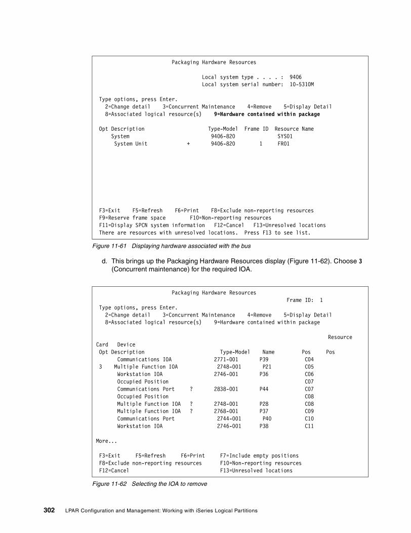
Figure 11-61 Displaying hardware associated with the bus
d. This brings up the Packaging Hardware Resources display (Figure 11-62). Choose 3 (Concurrent maintenance) for the required IOA.
Figure 11-62 Selecting the IOA to remove
Packaging Hardware Resources Local system type . . . . : 9406 Local system serial number: 10-5310M Type options, press Enter. 2=Change detail 3=Concurrent Maintenance 4=Remove 5=Display Detail 8=Associated logical resource(s) 9=Hardware contained within package Opt Description Type-Model Frame ID Resource Name System 9406-820 SYS01 System Unit + 9406-820 1 FR01 F3=Exit F5=Refresh F6=Print F8=Exclude non-reporting resources F9=Reserve frame space F10=Non-reporting resources F11=Display SPCN system information F12=Cancel F13=Unresolved locations There are resources with unresolved locations. Press F13 to see list.
Packaging Hardware Resources Frame ID: 1 Type options, press Enter. 2=Change detail 3=Concurrent Maintenance 4=Remove 5=Display Detail 8=Associated logical resource(s) 9=Hardware contained within package Resource Card Device Opt Description Type-Model Name Pos Pos Communications IOA 2771-001 P39 C04 3 Multiple Function IOA 2748-001 P21 C05 Workstation IOA 2746-001 P36 C06 Occupied Position C07 Communications Port ? 2838-001 P44 C07 Occupied Position C08 Multiple Function IOA ? 2748-001 P28 C08 Multiple Function IOA ? 2768-001 P37 C09 Communications Port 2744-001 P40 C10 Workstation IOA 2746-001 P38 C11 More... F3=Exit F5=Refresh F6=Print F7=Include empty positions F8=Exclude non-reporting resources F10=Non-reporting resources F12=Cancel F13=Unresolved locations
302 LPAR Configuration and Management: Working with iSeries Logical Partitions

e. The Hardware Resource Concurrent Maintenance display (Figure 11-63) appears. In this example, we selected a DASD IOA so we would have verified previously that the DASD was not configured. Now we need to work with the controlling resource to relinquish the IOA. In this case, the combined function IOP owns the adapter, so we type 9 in front of it.
Figure 11-63 Concurrent maintenance IOA
f. You now see the Work with Controlling Resource display (Figure 11-64).
Figure 11-64 Work with Controlling Resource
Hardware Resource Concurrent Maintenance Frame ID: 1 Type options, press Enter. 2=Toggle LED blink off/on 5=Display detail 8=Associated logical resource(s) 9=Work with controlling resource Power Card Device Opt Description Type-Model Status Pos Pos 9 Multiple Function IOA > 2748-001 On C05 F3=Exit F5=Refresh F6=Print F8=Display resource names F9=Power off domain F10=Power on domain F11=In-use resources F12=Cancel
Work with Controlling Resource Frame ID: 1 Selected resource: Resource Card Device Description Type-Model Name Pos Pos Multiple Function IOA 2748-001 P21 C05 Type options, press Enter. 5=Display detail 6=Relinquish from 7=Assign to 8=Associated packaging resource(s) Resource Opt Description Type-Model Status Name Combined Function IOP *> 284C-001 Operational CMB01 F3=Exit F5=Refresh F6=Print F12=Cancel
Chapter 11. Configuring Linux in a guest partition 303
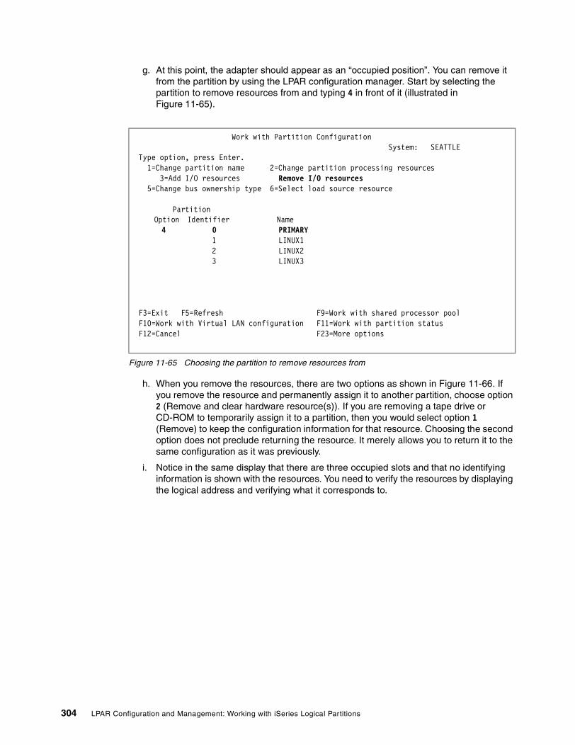
g. At this point, the adapter should appear as an “occupied position”. You can remove it from the partition by using the LPAR configuration manager. Start by selecting the partition to remove resources from and typing 4 in front of it (illustrated in Figure 11-65).
Figure 11-65 Choosing the partition to remove resources from
h. When you remove the resources, there are two options as shown in Figure 11-66. If you remove the resource and permanently assign it to another partition, choose option 2 (Remove and clear hardware resource(s)). If you are removing a tape drive or CD-ROM to temporarily assign it to a partition, then you would select option 1 (Remove) to keep the configuration information for that resource. Choosing the second option does not preclude returning the resource. It merely allows you to return it to the same configuration as it was previously.
i. Notice in the same display that there are three occupied slots and that no identifying information is shown with the resources. You need to verify the resources by displaying the logical address and verifying what it corresponds to.
Work with Partition Configuration System: SEATTLE Type option, press Enter. 1=Change partition name 2=Change partition processing resources 3=Add I/O resources Remove I/O resources 5=Change bus ownership type 6=Select load source resource Partition Option Identifier Name 4 0 PRIMARY 1 LINUX1 2 LINUX2 3 LINUX3 F3=Exit F5=Refresh F9=Work with shared processor pool F10=Work with Virtual LAN configuration F11=Work with partition status F12=Cancel F23=More options
304 LPAR Configuration and Management: Working with iSeries Logical Partitions

Figure 11-66 Removing resources
j. The next display (Figure 11-67) allows you to verify that this is what you want to do. Press Enter to confirm your choice.
Figure 11-67 Confirming removal of resource
Remove I/O Resources System: SEATTLE Level of detail to display . . . . . . *ALL *ALL, *BUS, *IOP, *IOA, *DEV Partition identifier . . . . . . . . . . . . . : 0 Partition name . . . . . . . . . . . . . . . . : PRIMARY Type options, press Enter. 1=Remove 2=Remove and clear hardware resource(s) I/O Resource Serial Part Opt Description Type-Model Number Number Occupied Position System Bus 24 283B- 38-0293021 04N4723 2 Occupied Position Occupied Position Occupied Position Bottom * Indicates load source. F3=Exit F9=Toggle empty pos F10=Display logical address F12=Cancel
Confirm Remove I/O Resources System: SEATTLE Press Enter to confirm your choice to remove the following I/O resources from this partition. Removals can only be made at a bus or I/O processor level. Press F12 to return to change your choice. Partition identifier . . . . . . . . . . . . . : 0 Partition name . . . . . . . . . . . . . . . . : PRIMARY I/O Resource Serial Part Description Type-Model Number Number Occupied Position * Indicates load source. F10=Display logical address F12=Cancel
Chapter 11. Configuring Linux in a guest partition 305

k. To add the resources that you just removed, use the LPAR configuration manager and choose Work with partition configuration. A display like the example shown in Figure 11-68 appears. Type 3 next to the partition to add the resource to it. Press Enter.
Figure 11-68 Choosing a partition to add resources to LINUX1
l. The Add I/O Resources display (Figure 11-69) appears. The only option that applies to an IOA is option 1 (Own dedicated). Select this option.
Figure 11-69 Adding an IOA
Work with Partition Configuration System: SEATTLE Type option, press Enter. 1=Change partition name 2=Change partition processing resources 3=Add I/O resources 4=Remove I/O resources 5=Change bus ownership type 6=Select load source resource Partition Option Identifier Name 0 PRIMARY 3 1 LINUX1 2 LINUX2 F3=Exit F5=Refresh F9=Work with shared processor pool F10=Work with Virtual LAN configuration F11=Work with partition status F12=Cancel F23=More options
Add I/O Resources System: SEATTLE Level of detail to display . . . . . . *ALL *ALL, *BUS, *IOP, *IOA, *DEV Partition identifier . . . . . . . . . . . . . : 1 Partition name . . . . . . . . . . . . . . . . : LINUX1 Type options, press Enter. 1=Own dedicated 2=Own bus shared 3=Use bus shared I/O Resource Serial Part Opt Description Type-Model Number Number System Bus 23 283B- 38-0293021 04N4723 System Bus 24 283B- 38-0293021 04N4723 1 Occupied Position F3=Exit F9=Toggle empty pos F10=Display logical address F12=Cancel
306 LPAR Configuration and Management: Working with iSeries Logical Partitions

m. On the Confirm Add I/O Resources display (Figure 11-70), press Enter to confirm your choice.
Figure 11-70 Confirming add IOA
n. Navigate to the main configuration screen (Figure 11-71). Choose option 1 (Display partition information) to confirm the successful addition.
Figure 11-71 Displaying partition information
Confirm Add I/O Resources System: SEATTLE Press Enter to confirm your choice to add the following I/O resources to this partition. Press F12 to return to change your choice. Partition identifier . . . . . . . . . . . . . : 1 Partition name . . . . . . . . . . . . . . . . : LINUX1 I/O Resource Serial Part Opt Description Type-Model Number Number 1 Occupied Position F10=Display logical address F12=Cancel
Work with System Partitions System: SEATTLE Attention: Incorrect use of this utility can cause damage to data in this system. See service documentation. Number of partitions . . . . . . . : 3 Partition manager release . . . . . : V5R1M0 L000 Partition identifier . . . . . . . : 0 Partition name . . . . . . . . . . : PRIMARY * Select one of the following: 1. Display partition information 2. Work with partition status 3. Work with partition configuration 4. Recover configuration data 5. Create a new partition Selection F3=Exit F12=Cancel
Chapter 11. Configuring Linux in a guest partition 307

o. On the Display Partition Information panel (Figure 11-72), choose option 3 (Display allocated I/O resources).
Figure 11-72 Displaying allocated resources
Generic Adapter should be displayed on the bus as shown in Figure 11-73.
Figure 11-73 Displaying the IOA that was added
Display Partition Information System: SEATTLE Select one of the following: 1. Display partition status 2. Display partition processing configuration 3. Display allocated I/O resources 4. Display available I/O resources 5. Display system I/O resources 6. Display partition operating environment 7. Display communication options 8. Display secondary partition reference code history 9. Display guest environment host information 10. Display guest environment console log Selection D F3=Exit F12=Cancel
Display Allocated I/O Resources System: CSITLIN2 System partition(s) to display . . . . *ALL *ALL, 0-2 Level of detail to display . . . . . . *ALL *ALL, *BUS, *IOP, *IOA, *DEV Par Serial Part ID Description Type-Model Number Number Occupied Position 1 LINUX1 Partition 9406-270 10-509BM System Bus 23 283B- 38-0293021 04N4723 Generic Adapter 274D- System Bus 24 283B- 38-0293021 04N4723 Occupied Position 2 LINUX2 Partition 9406-270 10-509BM Bottom * Indicates load source. F3=Exit F5=Refresh F6=Print F9=Toggle empty pos F10=Display logical address F11=Display partition status F12=Cancel
308 LPAR Configuration and Management: Working with iSeries Logical Partitions

Adding new adaptersThe previous examples used existing resources. New adapters are automatically allocated by an upstream IOP on a bus owned by OS/400. If an IOP is not present, the adapter is identified as occupied position. The resource would have a default owner of the bus. If the bus is owned by the guest partition, then no further action is required. If the bus is owned by OS/400, you must remove the adapter and add it to the Linux partition. Before you add a new IOA, remove an “empty slot” and add it to the Linux partition. You should do this to ensure that an IOP does not automatically allocate the card, causing extra steps to remove it from the IOP.
Reassigning adaptersTo reassign an adapter to an IOP, remove it from the guest partition, using the same procedures as above. Using concurrent maintenance under the hardware service manager following essentially the same procedures as above, assign the adapter to an IOP. On a system IPL, normal rules prevail and the adapter will be assigned to the IOP.
Native (SCSI support): Supported devices and DASDNative DASD support is actually a SCSI driver that provides an interface for the Linux drivers to communicate with for OS/400 tape, optical, and DASD devices. It is a proprietary driver, but is believed that it will become part of the distributions and may well be bound into the kernel. However, it will be available on an IBM Web site (most likely http://ltc.linux.ibm.com/ or a link off of this site). If you are unable to locate it at this site, you can check current information at: http://www-1.ibm.com/servers/eserver/iseries/linux/
There will be a configuration utility to configure direct attached DASD that will be called using the sysconfig command and will use sisupdate to update the firmware. It presents an OS/400-type display to configure disk from Linux.
The SCSI driver itself is ibmsis.o. Also the following Linux drivers are required:
� sd.o: SCSDASD driver� st.o: SCSI Tape driver� sr.o: SCSI CD-ROM driver� scsi_mod.o: SCSI driver
The supported devices are listed in Table 11-3.
Table 11-3 List of supported devices
Native LAN adapters If you have multiple LAN adapters and can dedicate one or more to Linux, you may consider doing so. A dedicated adapter eliminates the extra hop that must be travelled when using the virtual LAN to communicate with the network and the routing and subnet issues that we described in the virtual LAN configuration. Once the hardware is allocated (see “Allocating resources” on page 287), it is a simply matter of configuring Linux, since OS/400 does not truly know of the existence of the hardware. The configuration for the native adapter is totally
Attention: Hardware RAID and disk compression are not supported.
Adapter Feature code Type
D/T2763 0604 Ultra-2 SCSI disk and tape controller - 10 MB Cache
D/T4748 0605 Ultra-2 SCSI disk and tape controller - 26 MB Cache
D/T4778 0606 disk and tape controller (need full description)
Chapter 11. Configuring Linux in a guest partition 309

within Linux. There are no OS/400 objects to configure so it is strictly a matter of using the ifconfig and route commands for basic configuration of Linux networking. For more details, see “Configuring Linux for the virtual LAN” on page 285 or Linux on the IBM ~ iSeries Server: An Implementation Guide, SG24-6232, for a more detailed explanation of Linux networking.
The code that was supplied by IBM is similar to that for native DASD and should be bound into the kernel. It actually provides a PCI interface so that the Linux drivers can locate and communicate to the iSeries hardware. The supported LAN devices are presented in Table 11-4.
Table 11-4 List of native LAN adapters
Configuring for a non-hosted partitionAt this time, this environment is still being tested, and as noted previously, Red Hat does not currently support directly attached IOA. Ultimately it is planned that, during the installation, there will be an option to install to native DASD.
The process today is to build a RAM disk that contains the ibmsis.o device driver and attach it to the kernel, change the IPL parameters in the NWSD to point to the location of the root file system, and instruct the kernel to load the /linuxrc script file as init. An example is shown in Figure 11-74.
Figure 11-74 Example of parameters for non-hosted installation
The root file system is then copied to native DASD and the /etc/fstab file is changed to reflect the file system. Please note this is strictly an example to illustrate how this can be done, and the actual path will vary. Furthermore, this is not planned to be the process, but may be helpful in understanding the process and debugging if problems occur. For information on RAM disks, review the help text presented with the Linux command man ram disk.
Adapter Feature code Type
D/T2743 0601 1 Gbps Ethernet
D/T2760 0602 1 Gbps Ethernet UTP
D/T2744 0603 4/16/100 Mbps Token Ring
D/T4838 0607 10/100 Mbps Ethernet
Change Network Server Desc (CHGNWSD) Type choices, press Enter. IPL source . . . . . . . . . . . *NWSSTG *SAME, *NWSSTG, *PANEL... IPL stream file . . . . . . . . *SAME IPL parameters . . . . . . . . . root=/dev/scsi/host0/bus0/target3/lun0/part2init=/linuxrc ro Text 'description' . . . . . . . *BLANK Bottom F3=Exit F4=Prompt F5=Refresh F12=Cancel F13=How to use this display F24=More keys
310 LPAR Configuration and Management: Working with iSeries Logical Partitions

To boot from the native DASD rather than relying on an NWS, it is necessary to use the Linux dd command to place the kernel and RAM disk into /proc/iSeries/mf/[A|B]/vmlinux.
11.3.4 General operationsThis section explains the general operations to start and stop the server on a hosted partition and on a non-hosted partition:
� On a hosted partition:
– Use the VRYCFG command with *ON or *OFF as shown in Figure 11-75.
When working with a hosted partition, you can use the VRYCFG command as shown in Figure 11-75 or the WRKCFGSTS *NWS command and then vary off your server with options 1 or 2.
Figure 11-75 Varying on a hosted partition
– When working with your Linux drives (or storage spaces), use the WRKNWSSTG command, plus ADDNWSSTG for adding drives and RMVSSTG to remove drives or delete drives (Figure 11-76).
Vary Configuration (VRYCFG) Type choices, press Enter. Configuration object . . . . . . > LINUX1 Name, generic*, *ANYNW... + for more values Type . . . . . . . . . . . . . . > *NWS *NWS, *NWI, *LIN, *CTL... Status . . . . . . . . . . . . . > *ON *ON, *OFF, *RESET... Range . . . . . . . . . . . . . *NET *NET, *OBJ Vary on wait . . . . . . . . . . *CFGOBJ *CFGOBJ, *NOWAIT, 15-180 (sec) Asynchronous vary off . . . . . *NO *NO, *YES Reset . . . . . . . . . . . . . *NO *NO, *YES Resource name . . . . . . . . . Name, *ALL + for more values Reset configuration file . . . . *NO *NO, *YES Forced vary off . . . . . . . . *NO *NO, *YES, *LOCK Start TCP/IP interfaces . . . . *YES *NO, *YES Submit multiple jobs . . . . . . *NO *NO, *YES Job description . . . . . . . . QBATCH Name Library . . . . . . . . . . . *LIBL Name, *LIBL Bottom F3=Exit F4=Prompt F5=Refresh F12=Cancel F13=How to use this display F24=More keys
Chapter 11. Configuring Linux in a guest partition 311

Figure 11-76 Working with storage
– When considering backing up or saving these drives or storage spaces, use the SAV command. When backing up drives or storage spaces, the server must be varied off. Incremental backups are not supported via the OS/400 SAV command. You must use Linux native commands and applications to do incremental backups
Work with Network Server Storage Spaces System: SEATTLE Type options, press Enter. 1=Create 3=Copy 4=Delete 5=Display 6=Print 10=Add link 11=Remove link Percent Opt Name Used Size Server Drive Format Access ASP HIHIHO 0 10 REDHAT71 4 *OPEN *UPDATE 1 LINUX2ALT 0 1800 REDHAT71 2 *OPEN *UPDATE 1 NEWLIN 0 800 REDLIN 1 *OPEN *UPDATE 1 REDHBTWO 0 2000 REDHAT7B 2 *OPEN *UPDATE 1 RHBETA7B 0 1536 REDHAT7B 1 *OPEN *UPDATE 1 RHBETA71 0 1536 *OPEN 1 RHSMALL 0 1280 *NTFS 1 SECONDLIN 0 200 REDLIN 2 *OPEN *UPDATE 1 TEMP 0 1 REDHAT71 5 *OPEN *UPDATE 1 More... Parameters or command ===> F3=Exit F4=Prompt F5=Refresh F6=Print list F9=Retrieve F11=Display text F12=Cancel F17=Position to
312 LPAR Configuration and Management: Working with iSeries Logical Partitions

� On a non-hosted partition:
– When starting or stopping the server, use the appropriate options from the Virtual Service panel as shown in Figure 11-77.
Figure 11-77 Virtual service panel
– There is no save capability from OS/400 side since the non-hosted is independent of OS/400. Most options would be Linux alternatives.
– Use the virtual LAN to FTP or Telnet to other partitions.
11.4 Managing Linux in a guest partitionThis section contains information about managing a partition running Linux. It explains how to IPL a partition running Linux and how to communicate and share information between a Linux partition and an OS/400 partition. You can find additional information on managing a V5R1 partition in Linux on the IBM ~ iSeries Server: An Implementation Guide, SG24-6232. You should also look in the Linux distributor information where specific Linux task management is required. This section covers:
� Displaying the console log for the guest partition: View the console log for each guest partition running on your system.
� Displaying guest partition host information: Verify which OS/400 partition is hosting a guest partition.
� Displaying operating environment of secondary partitions: Find out what version of the operating system is running in secondary partitions.
� Displaying reference code history for secondary partitions: View system reference code history for secondary partitions.
� Using virtual LAN in a guest partition: Understand how to share data between an OS/400 partition and a guest partition running Linux.
� Creating an Ethernet line description for virtual LAN: Learn how to create an Ethernet line description for virtual LAN.
Work with Partition Status System: SEATTLE Type options, press Enter. 1=Power on 3=IPL restart 7=Delayed power off 8=Immediate power off 9=Mode normal 10=Mode manual 11=Mode auto 12=Mode secure A=Source A B=Source B C=Source C D=Source D Partition IPL IPL Sys IPL Reference Opt Identifier Name Source Mode State Action Codes 0 PRIMARY B Normal On IPL 1 LINUX1 C Manual On Hold PROG FFFF 2 LINUX2 B Manual On Hold PROG FFFF 3 LINUX3 A Manual On Hold PROG FFFF F3=Exit F5=Refresh F10=Monitor partition status F11=Work with partition configuration F12=Cancel F23=More options
Chapter 11. Configuring Linux in a guest partition 313

� Printing system configuration for logical partitions: Use Dedicated Service Tools or System Service Tools to print copies of your system hardware configuration.
� Deciding what IPL type to use when running Linux: Learn how you can safely IPL a partition running Linux.
� Booting from the A or B IPL source: Understand the advantages and disadvantages of booting from the A or B IPL source and who has authority to perform the task.
11.4.1 Displaying the console log for the guest partitionYou can use the display console log for the guest partition to see console information for the guest partition running Linux.
You can perform this procedure from System Service Tools or Dedicated Service Tools on the primary partition. To use the Display Guest Environment Console Log display, follow these steps:
1. On the primary partition, start SST or DST.
2. From SST, select option 5 (Work with system partitions); from DST, select option 11 (Work with system partitions). Then press Enter.
3. Select option 1 (Display partition information).
4. Select option 10 (Display guest environment console log).
Once you are in Display Guest Environment Console Log, you can see console information for the guest partition.
11.4.2 Displaying guest partition host informationA hosted guest partition is dependent on an OS/400 partition for I/O resources. The hosting OS/400 partition can either be a primary or a secondary partition. You can use the display guest environment host information to view which OS/400 partition is hosting a guest partition.
You can perform this procedure from System Service Tools or Dedicated Service Tools on the primary partition. To use the Display Guest Environment Host Information display, follow these steps:
1. On the primary partition, start SST or DST.
2. From SST, select option 5 (Work with system partitions); from DST, select option 11 (Work with system partitions). Then press Enter.
3. Select option 1 (Display partition information).
4. Select option 9 (Display guest environment host information).
Once you are in Display Guest Environment Host Information, you can see the hosting partition of the guest partition.
11.4.3 Displaying operating environment of secondary partitionsYou can use the display partition operating environment display to see which release of the operating system each logical partition is running.
You can perform this procedure from System Service Tools or Dedicated Service Tools on the primary partition. To use the Display Partition Operating Environment display, follow these steps:
314 LPAR Configuration and Management: Working with iSeries Logical Partitions

1. On the primary partition, start SST or DST.
2. From SST, select option 5 (Work with system partitions); from DST, select option 11 (Work with system partitions). Then press Enter.
3. Select option 1 (Display partition information).
4. Select option 6 (Display partition operating environment).
Once you are in Display Partition Operating Environment, you can see what version of the operating system each logical partition is running.
11.4.4 Displaying reference code history for secondary partitionsA reference code indicates a status or an error condition. The system records the reference code history (the last 200 reference codes) for secondary partitions. You can use the Display secondary partition reference code history option to view the reference code history for secondary partitions.
You can perform this procedure from System Service Tools or Dedicated Service Tools on the primary partition. To display logical partition reference codes, follow these steps:
1. On the primary partition, start SST or DST.
2. From SST, select option 5 (Work with system partitions); from DST, select option 11 (Work with system partitions). Then press Enter.
3. Select option 1 (Display partition information).
4. Select option 8 (Display secondary partition reference code history).
Once you are in Display Secondary Partition Reference Code History, you can see the system reference codes of each logical partition.
11.4.5 Using virtual LAN in a guest partitionA guest partition can use virtual LAN to establish multiple high speed interpartition connections. Logical partition software allows you to configure up to 16 different virtual local area networks. Virtual LAN provides the same function as using a 1 GB Ethernet adapter. OS/400 and Linux partitions can communicate with each other using TCP/IP over the virtual LAN communication ports.
The enablement and setup of virtual LAN requires a restart of the Linux partition, but does not require any special hardware or software. Once a specific virtual LAN is enabled for a guest partition, a network device vethXX is created in the guest partition. The user can then set up TCP/IP configuration appropriately to start communicating with another partition. Virtual LAN provides the capability to provide multiple communication paths between applications that are run in each of the partitions.
Refer to the Linux for iSeries Web site for the latest updates to Linux running on an iSeries. You can find it at: http://www-1.ibm.com/servers/eserver/iseries/linux/
11.4.6 Creating an Ethernet line description for virtual LANCreating an Ethernet line description is the first step in configuring OS/400 to use virtual LAN. This configuration allows a guest partition to communicate an OS/400 partition using virtual LAN.
To configure a new Ethernet line description to support virtual LAN, complete the following steps:
Chapter 11. Configuring Linux in a guest partition 315

1. At the OS/400 command line, type:
WRKHDWRSC *CMN
Press Enter.
2. From the Work with Communication Resources display, select option 7 (Display resource detail) next to the appropriate virtual LAN Ethernet port. The Ethernet port identified as a 268C is the virtual LAN resource. There will be one for each virtual LAN that is connected to the partition.
3. From the Display Resource Detail display, scroll down to find the port address. The port address corresponds to the virtual LAN you selected during the configuration of the partition.
4. From the Work with Communication Resources display, type option 5 (Work with configuration descriptions) next to the appropriate virtual LAN Ethernet port and press Enter.
5. From the Work with Configuration Descriptions display, select option 1 (Create) enter the name of the line description and press Enter.
6. From the Create Line Description Ethernet (CRTLINETH) display, provide the following information:
RSRCNAMELINESPEED (1G)DUPLEX (*FULL)
Press Enter.
Enter the Maximum frame size (8996). By changing the frame size to 8996, the transfer of data across the virtual LAN is improved. Press Enter.
7. From the Work with Configuration Description display, you see a message stating the line description has been created.
11.4.7 Printing system configuration for logical partitionsIf you are running OS/400 V5R1 on the primary and all of the other partitions on the system are running Linux, we strongly recommend that you print the system configuration for all of your I/O resources. Logical partition configuration information is not saved during the save process. Therefore a printout is required to allocate appropriate resources should you have to recover your system in a disaster recovery scenario.
You also need to print the system configuration report for all logical partitions should you need to perform an Miscellaneous Equipment Specification (MES) also known as a hardware upgrade to your system with logical partitions. This information will assist your IBM Business Partner or IBM Marketing Representative to understand how your system I/O resources are assigned to the logical partitions.
Follow these steps to print the system configuration:
1. From the primary partition start SST or DST.
2. From SST, select option 5 (Work with system partitions); from DST, select option 11 (Work with system partitions) and press Enter.
Attention: Printing a rack configuration listing through Hardware Service Manager within SST only provides you with a configuration listing of the resources that are allocated to that specific partition. This report does not provide you with details for the entire system. For this reason, you should use the steps outlined here using the primary partition.
316 LPAR Configuration and Management: Working with iSeries Logical Partitions

3. Select option 1 (Display partition information).
4. Select option 5 (Display system I/O resources).
5. At the Level of detail to display field, type *ALL to set the level of detail to ALL.
6. Press F6 to print the system I/O configuration.
7. Select option 1 and press Enter to print to a spooled file.
8. Press F12 to return to the Display Partition Information display.
9. Select option 2 (Display partition processing configuration).
10.Press F6 to print the processing configuration.
11.Press F12 to return to Display Partition Information display.
12.Select option 7 (Display communications options).
13.Press F6 to print communication configuration.
14.Select option 1 and press Enter to print to a spooled file.
15.Return to an OS/400 command line and print these three spooled files.
11.4.8 Deciding what IPL type to use when running LinuxThe IPL type parameter on the NWSD determines the source from which a guest operating system is loaded. The first thing to understand is that, on an iSeries server, the IPL comes from one of four locations managed by the LPAR configuration. These four locations are called A, B, C, and D. The initial program (which in the case of Linux is the Linux kernel) can be loaded into these locations two ways:
� From Linux itself� The C location can be loaded by OS/400 using a network server description (NWSD)
The NWSD itself has a parameter called IPLSRC that specifies from where the guest partition is to be loaded. Table 11-5 shows the values that the IPL type parameter can have.
Table 11-5 IPL type parameter on the NWSD
IPLSRC values Description
A Load the guest partition from location A. Location A must have been previously loaded with a kernel from Linux. IBM recommends using the A location to store a stable, known kernel.
B Load the guest partition from location B. Location B must have been previously loaded with a kernel from Linux. IBM recommends using B for testing new kernels.
D IBM Support reserves this type of IPL for future use.
*Panel The partition is started from the source indicated on the operator’s panel.
*NWSSTG (network server storage space)
This IPL type is used to boot a partition from a virtual disk. OS/400 will find the kernel in the virtual disk and load it in location C. Then the partition will be set to IPL from C. OS/400 searches the first virtual disk connected to the NWSD for a partition marked bootable, and of type 0x41 (PReP boot). The contents of this location are loaded in C. If a partition of this type does not exist, the partition will fail.
Chapter 11. Configuring Linux in a guest partition 317

Booting from the LPAR configuration displayThe LPAR configuration display can be used to set a guest partition to IPL from four locations. These locations are A, B, C, and D. Currently D is reserved for future use.
The IPL type determines which copy of programs your system uses during the initial program load (IPL). These parameter can have the values listed in Table 11-6.
Table 11-6 Partition IPL source descriptions
Booting from the A and B IPL sourceA guest partition running Linux can boot from either the A or B IPL source. However, Linux must be installed on the system and previously loaded from a different source before this option can be used.
Administration authority must be obtained before performing this task. For more information on how to configure user profiles, refer to Chapter 6, “Operating LPAR environments” on page 103.
To copy a kernel into the A or B IPL source, the /proc file system is used. The command used to copy the kernel into the A or B IPL source is:
dd if=/usr/src/linux/vmlinux.trimof=/proc/iSeries/mf/A/vmlinux bs=4096
The advantage of using this boot source is that Linux boots faster. A disadvantage is that the boot source cannot be saved or restored. It is also difficult to tell which IPL source has stored the kernel.
*STMF (stream file) This IPL type is used to boot a partition from a kernel loaded in the OS/400 Integrated File System. Note that the Integrated File System includes files on the Optical (CD) drive on OS/400. OS/400 will load the specified file into the C location and the partition will be set to IPL from C. This is typically how initial Linux installations are performed.
IPLSRC values Description
A Load the guest partition from location A. Location A must have been previously loaded with a kernel from Linux. IBM recommends using the A location to store a stable, known kernel.
B Load the guest partition from location B. Location B must have been previously loaded with a kernel from Linux. IBM recommends using B for testing new kernels.
C This IPL type is typical used when a partition is loading from a network server description (NWSD) or a stream file (STMF). Refer to *NWSSTG for more information on how the C IPL type is used.
D IBM Support reserves this type of IPL for future use.
IPLSRC values Description
318 LPAR Configuration and Management: Working with iSeries Logical Partitions

11.5 Troubleshooting the iSeries with Linux running in a guest partition
This sections helps you to understand how to analyze and resolve errors specific to Linux running on the iSeries server. If your problem is specific to logical partitions, refer to Chapter 9, “Logical partition problem management” on page 213, and Appendix B, “System reference codes (SRCs) and messages” on page 397, for additional assistance. Linux-specific troubleshooting issues require the assistance of your preferred Linux distributor:
� Debugging NWSD error messages
Find a list of error codes and messages related to problems with the network server description.
� Debugging the processor multitasking error
Understand how to determine whether your server should have the processor multitasking function disabled.
� Resolving system reference codes for Linux
Find a list of system reference codes specific to Linux and suggested corrective actions for resolving errors.
11.5.1 Debugging NWSD error messagesYou could encounter error messages when you try to vary on a Linux partition. These error messages appear if you provide information when you create your NWSD that does not apply to a guest partition running on the system. All error messages related to the NWSD should appear in QSYSOPR indicating a description of the problem and a resolution to the issue. Table 11-7 shows the NWSD error messages.
Table 11-7 NWSD error messages
Reason codes Code explanations
00000001 *NWSSTG was specified as the IPL source, but no storage space was found.
00000002 The partition specified in the PARTITION parameter was not found.
00000003 The partition specified in the PARTITION parameter is not a guest partition.
00000004 There is already a NWSD in the OS/400 partition that is active and using the partition specified in the PARTITION parameter of the NWSD.
00000005 The partition specified in the PARTITION parameter of the NWSD is powered on (perhaps through the LPAR configuration interface or from another OS/400 partition).
00000006 The partition is set to boot from a stream file (stmf) and for some reason that didn’t work. You should note that the user performing the vary on needs read access to the IPL STMF parameter.
00000007 The NWSD is set to boot from a storage space (NWSSTG), but for some reason the kernel could not be found. Some common reasons are no type 0x41 partition or not marked bootable.
00000008 The partition would not start. There are a variety of reasons why the partition will not start. You could have a corrupt kernel or the processor feature code does not support the shared processor pool. If the kernel and processor are not the problem, you need to look at the information for this partition and start reviewing the SRCs.
Chapter 11. Configuring Linux in a guest partition 319
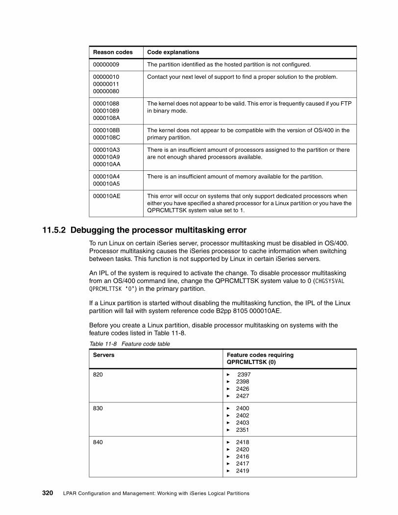
11.5.2 Debugging the processor multitasking errorTo run Linux on certain iSeries server, processor multitasking must be disabled in OS/400. Processor multitasking causes the iSeries processor to cache information when switching between tasks. This function is not supported by Linux in certain iSeries servers.
An IPL of the system is required to activate the change. To disable processor multitasking from an OS/400 command line, change the QPRCMLTTSK system value to 0 (CHGSYSVAL QPRCMLTTSK ‘0’) in the primary partition.
If a Linux partition is started without disabling the multitasking function, the IPL of the Linux partition will fail with system reference code B2pp 8105 000010AE.
Before you create a Linux partition, disable processor multitasking on systems with the feature codes listed in Table 11-8.
Table 11-8 Feature code table
00000009 The partition identified as the hosted partition is not configured.
00000010 00000011 00000080
Contact your next level of support to find a proper solution to the problem.
00001088 00001089 0000108A
The kernel does not appear to be valid. This error is frequently caused if you FTP in binary mode.
0000108B 0000108C
The kernel does not appear to be compatible with the version of OS/400 in the primary partition.
000010A3 000010A9 000010AA
There is an insufficient amount of processors assigned to the partition or there are not enough shared processors available.
000010A4 000010A5
There is an insufficient amount of memory available for the partition.
000010AE This error will occur on systems that only support dedicated processors when either you have specified a shared processor for a Linux partition or you have the QPRCMLTTSK system value set to 1.
Reason codes Code explanations
Servers Feature codes requiring QPRCMLTTSK (0)
820 � 2397� 2398� 2426� 2427
830 � 2400� 2402� 2403� 2351
840 � 2418� 2420� 2416� 2417� 2419
320 LPAR Configuration and Management: Working with iSeries Logical Partitions

11.5.3 Resolving system reference codes for LinuxThe following list contains SRCs specific to Linux and suggested corrective actions. To display SRCs, see Appendix B, “System reference codes (SRCs) and messages” on page 397, for a list of the last 200 reference codes for a partition. This appendix also contains additional SRCs for logical partitions. If an SRC is not listed, it may not be related to logical partitions. In this case, you should consult Chapter 9, “Logical partition problem management” on page 213, or your next level of service.
Once you learn about system reference codes for logical partitions, you can understand what SRCs are and how to identify them:
� B2pp 1270 (pp equals the partition ID)
– Cause: A problem occurred during the IPL of a secondary partition running Linux. The partition cannot IPL because the primary partition must be in a full paging environment.
– Recovery: IPL the primary partition past the Storage Management full paging IPL step.
– Problem analysis procedure: Check the IPL mode of the primary partition and the failing secondary partition. If the primary partition is in C mode, the guest partition will not IPL.
� B2pp 6900 (pp equals the partition ID)
– Cause: The size of the secondary partition’s kernel exceeds the size allocated for the load area by the secondary partition.
– Recovery: Verify the size of the secondary partition’s memory allocation is large enough to load the kernel. Ensure the kernel is correct.
– Problem analysis procedure: Identify the values for words 3 and 4 to determine the cause of the error. The values for the words are as follows:
• Word 3: Allocated size of the secondary partition• Word 4: Required size of the kernel
� B2pp 6905 (pp equals the partition ID)
– Cause: A problem occurred during the IPL of a secondary partition running Linux. The kernel is not valid for the specified IPL mode for the guest partition. The kernel is not available for the IPL mode.
– Recovery: Verify that the kernel specified to load is valid and the IPL mode specified is where the kernel is located.
– Problem analysis procedure: Check processor and memory allocations to the secondary partition. You should make sure there are enough functioning processors and memory resources in the system for the partition.
� B2pp 6910 (pp equals the partition ID)
– Cause: A problem occurred during the IPL of a secondary partition running Linux. A storage management problem occurred while loading the guest partition.
– Recovery: Collect the detailed hexadecimal data from the hosting partition and contact your next level of support.
– Problem analysis procedure: Check processor and memory allocations to the secondary partition. You should make sure there are enough functioning processors and memory resources in the system for the partition.
� B2pp 6920 (pp equals the partition ID)
– Cause: A problem occurred during the IPL of a secondary partition running Linux. A problem occurred while loading the guest partition.
Chapter 11. Configuring Linux in a guest partition 321

– Recovery: Collect the detailed hexadecimal data from the hosting partition and contact your next level of support.
– Problem analysis procedure: Review the SRC history of the hosting partition.
� B2pp 6930 (pp equals the partition ID)
– Cause: A problem occurred during the IPL of a secondary partition running Linux. A problem occurred while loading the guest partition.
– Recovery: Collect the detailed hexadecimal data from the hosting partition and contact your next level of support.
– Problem analysis procedure: Check processor and memory allocations to the secondary partition. You should make sure there are enough functioning processors and memory resources in the system for the partition.
� B2pp 8105 (pp equals the partition ID)
– Cause: Initialization of secondary partition main storage data structures failed. The IPL is ended.
– Recovery: This is likely a problem with the load source media being corrupt or invalid. A re-installation of the Licensed Internal Code of the secondary partition is probably required to recover. If it continues to fail, contact your service provider.
– Problem analysis procedure: Identify the reason code from word 13 of the SRC. The reason code value for word 13 is:
000000AE: Processor multitasking must be disabled in OS/400
11.6 SummaryLinux and the open source community have a very flexible and agile Internet presence and development community that can benefit the iSeries platform by providing exposure to the open source community and a multitude of other Internet applications. Linux is growing rapidly as a server platform and is attracting attention from many sources because of its reputation for stability, scalability, and flexibility available at very little immediate cost. In many cases, some of this cost may be offset by the need for in-house programming and support. This also implies the ability to provide very specific solutions rather than altering a shrink-wrapped solution that does not totally fit particular needs.
iSeries hardware and OS/400 provide a hardware/software platform of proven stability and world class performance. Little needs to be said in regard to the proven capabilities and broad popularity of OS/400, since this publication is directed at OS/400 users implementing Linux.
The iSeries can enhance the Linux environment by:
� Providing a hardware platform of proven reliability and stability – beyond that of most, if not all other, platforms that Linux is associated with
� The ability to share the OS/400 hardware providing access to large amounts of DASD and centralized management of resources
� Server consolidation as referenced above
� Potentially initiating interaction with a large portfolio of existing e-business and business applications
� A new customer base
322 LPAR Configuration and Management: Working with iSeries Logical Partitions

iSeries can derive the benefits of:
� Involvement in the open source community� New possibilities for Web applications and components� Leveraging IBM’s investment in Linux� Expanding its Internet flexibility and scope as the ability to integrate with Linux expands
Therefore, what may seem to be an odd “marriage” at first actually can prove to be a very profitable union in the future. It is in its infancy with this release, but there are still several viable options. Read on to discover some of the options.
Chapter 11. Configuring Linux in a guest partition 323

324 LPAR Configuration and Management: Working with iSeries Logical Partitions

Chapter 12. Basics of using the LPAR Validation Tool (LVT)
This chapter shows the basic steps for using the LPAR Validation Tool. They include:
� “Starting LVT from the desktop” on page 326� “Specifying the system information” on page 327� “Specifying hardware placements” on page 330� “Adding towers to the configuration” on page 333� “Performing the configuration validation” on page 333� “Printing the configuration report” on page 335� “Example 1: Three partitions on a 2-way Model 270” on page 336� “Example 2: Four partitions on a 4-way Model 830” on page 339
12
© Copyright IBM Corp. 2002 325

12.1 LVTThis section explains how to use LPAR Validation Tool (hereafter called LVT). This tool helps you to prepare the Planning Worksheet for the LPAR system. This tool is not a configurator and does not provide hardware prerequisites and co-requisites that may be needed. Please refer to IBM ~ iSeries Handbook Version 4 Release 1, GA19-5486, or IBM ~ iSeries and AS/400e Builder, Version 5 Release 1, SG24-2155, for more information on the hardware. Use of the LVT also presumes a working knowledge of LPAR design requirements and iSeries hardware.
The following steps help you to understand more about the tool and how to use it in validating an LPAR system configuration. Then in 12.2, “Sample LVT reports” on page 336, you can find some reports and how to read them.
The LVT and its User’s Guide are available for download, along with the Java Runtime Environment (JRE) for it at: http://www.iseries.ibm.com/lpar
You must download the provided JRE because unpredictable results may occur if a different JRE is used.
12.1.1 Starting LVT from the desktopSelect the LVT tool icon from the desktop or from the window’s menu. Figure 12-1 shows the first window that appears when the LVT is started.
Figure 12-1 LPARValidater window
326 LPAR Configuration and Management: Working with iSeries Logical Partitions

12.1.2 Designing a new system or open a saved design Select File and then New to create new system design. Select File and then Open to retrieve an existing design that was saved before. Figure 12-2 shows the window with the pull-down menu.
Figure 12-2 LPARValidater window with New option
12.1.3 Specifying the system informationIn this window, you specify the system that is going to implement LPAR. Figure 12-3 shows the window that appears for a new system. The following items explain the values that you need to include in the window:
� Select the primary partition’s operating system. If V4R5 is selected, then the system models shown are old AS/400 models. This does not include new Model 270s because old Model 270s cannot support LPAR. If you need the latest functions of LPAR, select V5R1 in the primary partition. The other reasons to select V5R1 in primary partition are:
– To create a thin primary partition. Thin primary partition was introduced in V5R1 to allow you to create a partition with minimal resources allocated to it.
– If the model that is needed is a new Model 270, then the primary partition needs to be in V5R1.
� Select the system model and the processor feature. System models and processor features can be selected from the pull-down box. When the mouse pointer is moved to the processor feature, it displays the CPW and number of processors for that feature.
� Select the interactive feature. The pull-down box displays all the valid interactive features for the system model that was selected. The CPW value is displayed when the mouse pointer is moved to the feature.
� Total number of memory for the entire system. The value must be in GB and cannot exceed the maximum or be less than the minimum memory for the system model selected. If the value selected is outside of the min/max memory, then an error message appears.
� Enter the total number of partitions being implemented in this system. This value cannot exceed the maximum value for the machine model. In V5R1, it allows you to create up to four partitions per processor. But the maximum number of partitions can exceed 32. This depends on the hardware availability of the system.
� If you selected a POD machine model, enter the number of active processors you will use for the entire system.
Chapter 12. Basics of using the LPAR Validation Tool (LVT) 327

Figure 12-3 New - System Selection window
12.1.4 Defining partition specification The New - Partition Specifications window (Figure 12-4) allocates memory, processors (shared or dedicated), and interactive for all partitions and operating system for the secondary partitions. On the top left side of the display, you see the system that was selected in the previous window. On the top right side, you see the total available resources for the selected system. These values will change as resources are allocated to the partitions.
Figure 12-4 Partition Specifications window
The following points explain how to fill in the information on this window:
� Select the primary partition’s console type. You can select the feature from the pull-down box. See Figure 12-5 for the window display. The valid V5R1 values are:
– 4746 - Twinaxial console– 2744 - Token-ring Operations Console LAN attached – 4838 - Ethernet Operations Console LAN attached
328 LPAR Configuration and Management: Working with iSeries Logical Partitions

– 9771 - Operations Console direct attached– 4745 - Operations Console direct attached (if upgrade from V4 system)
Figure 12-5 Selecting the console type for the primary partition
� Select the operating system for secondary partitions. The primary partition’s operating system cannot be changed. If needed, click Back to go to the previous windows and change the operating system for the primary partition. You may also change the name of secondary partitions (up to ten characters). Figure 12-6 shows the available operating systems and that “P1” has been changed to “Site One”.
Figure 12-6 Operating system selection for secondary partitions
� If this system has any shared processors, then specify the number of processors that are in the pool in the Shared Pool Processors field. When a value is specified in this box, it automatically reduces the amount from Dedicated Processors and moves to Shared Processors. Figure 12-7 shows what happens when processors are allocated to the Shared pool.
Chapter 12. Basics of using the LPAR Validation Tool (LVT) 329

Figure 12-7 Partition Specification - Shared Processor
� Specify whether the partition is sharing processors from the pool. When the check box is marked that means that the partition’s processors are taken from the shared pool. If this box is not marked, then this partition is using dedicated processors.
� Define the processor units or processors. If the shared box is marked then the value can be a decimal value. The minimum value for a partition is 0.1 processor. However, you can specify any amount above 0.1 in 0.01 increments. The total shared processor units may not exceed the number of processors in the shared pool.
� Batch CPW cannot be specified. It is automatically calculated when the processor value is entered.
� Enter the memory for the partition in the memory column. The values must be in MB. The minimum for the primary partition is 256 MB and 128 MB for secondary partitions (Linux partition minimum is 64 MB).
� Allocate the interactive resources in percentage or in CPW value. If a percentage is specified, then the CPW value is calculated based on the feature code selected. Likewise when the CPW is specified, the percentage is calculated automatically. Placing the cursor over the percentage field shows the allowed min/max interactive percent for that partition.
Once all these fields are filled in correctly, click Finish to proceed or Back to the previous window if you need to change the system model and feature codes.
12.1.5 Specifying hardware placementsThe window in Figure 12-8 shows the system unit for the selected model. Initially it selects the base cards for the model and places them in the correct slots. On the left side of the window, it shows all the possible IOPs, IOAs, DASDs, and Linux IOAs that can be selected. Under the description column, it shows IOP/IOA or IOA depending on what type of card can be placed in the slot. If you try to add a card that is not allowed in the slot, it shows an error message in the error code box at the bottom of this main window. When you want to add a card to a slot, you need to:
1. Select the feature from the left side of the window.2. Click Add on the desired slot.
Each of these steps is further explained on the following page.
330 LPAR Configuration and Management: Working with iSeries Logical Partitions

Figure 12-8 System Unit with base feature codes
Figure 12-9 shows adding an IOP to the system unit or expansion unit. When you click Add on a slot, a drop-down box is displayed for you to select the partition number. If the IOP is intended to be switched between partitions, then select Switchable. If the IOP is to be dedicated to a partition, then select the appropriate partition number from the list.
Figure 12-9 Adding an IOP to the system unit or expansion unit
Figure 12-10 shows how to add an IOA to a card slot. Select the IOA from the left side of the window and click the Add button in the system unit or expansion unit. If the IOA is valid for that slot, then it will be added to the slot and have the same partition ID as the IOP that controls that slot.
Chapter 12. Basics of using the LPAR Validation Tool (LVT) 331

Figure 12-10 Adding IOAs to system unit or expansion unit
Figure 12-11 shows how to add DASD to the system or expansion units. When the DASD is selected and the Add button clicked, it prompts for the number of disk units. This window shows the maximum units that the slot can accommodate. Select the amount you want and click OK to add the DASD to the slot. If you select fewer than the maximum, the tool will add extra positions DBx(a) & DBx(b) to provide other places for disk drives of a different size to be added if that is what is needed.
Figure 12-11 Adding DASD to the system or expansion unit
332 LPAR Configuration and Management: Working with iSeries Logical Partitions

12.1.6 Adding towers to the configuration When there is not enough space available in the system unit, you need to add a tower to the system. To add a tower to the system, select Edit-> Add Tower. This displays a drop-down box with all the possible towers. Select the tower you want to add and click OK. If the tower is not valid, then an error is displayed in error box and tower will not be added to the system. Figure 12-12 shows how the towers are added.
Figure 12-12 Adding towers to the system
12.1.7 Performing the configuration validationOnce all the cards required are placed, perform the validation. To perform this, select Validate and Validate Partitions. This validates all the partitions and displays any errors in the error box. If it finds any missing devices or cards, then it appears in the error box as well.
Figure 12-13 show the window that appears after performing the validation process.
Chapter 12. Basics of using the LPAR Validation Tool (LVT) 333

Figure 12-13 Validation process
12.1.8 Saving the configurationOnce the validation is done, make sure that the design is saved. Otherwise there is no method to retrieve it later. This tool does not automatically save the design. To save the design, select File-> Save As. Then it prompts for the file name. The LVT data must be saved as .xml files. See Figure 12-14 for more details.
Figure 12-14 Save options window
334 LPAR Configuration and Management: Working with iSeries Logical Partitions

12.1.9 Printing the configuration report To print the report, select the report. There is no print option available in this tool yet. Select the View option to view the report or Save As to save the report to a file. Then use some word processing program to print the report. You need to select a font and font size that allow proper spacing of columns in the report. The “Total” section of the summary can be used as a guide for entering data to the configurator. You should then cross check your configurator output against the LVT report totals to make sure they match.
When the view option is selected, it displays a window to select a summary or detail report. Select all if you need both. Otherwise select the report that you want and click OK to proceed. Figure 12-15 and Figure 12-16 show the process.
Figure 12-15 Report prompt window
Chapter 12. Basics of using the LPAR Validation Tool (LVT) 335

Figure 12-16 Sample report view
12.2 Sample LVT reportsThis section shows you some sample LVT reports and their descriptions. LVT reports are broken into two sections: Detail and Summary.
In the Detail section, you see “System Selections”, which shows the overall specifications of the system being designed. There is also “Partition Specifications”, which shows the Ver/Rel, shared status, processors, batch CPW, memory, interactive percent, and CPW. There is also “Tower Properties”, which shows you, by tower, the locations of all the hardware and to what partition or partitions that hardware belongs based on your input to the tool.
In the summary section, you are first shown the quantity of the features by partition, and secondly, you see the total features for the entire system. Where you see a number in the “Switchable” column, it is not in addition to, but part of the “Total” column.
12.2.1 Example 1: Three partitions on a 2-way Model 270This example shows three OS/400 partitions, all V5R1, on a 2-way Model 270 with a thin primary, arranged with two of the partitions sharing a processor and one with a dedicated processor. It provides for a switchable external CD on a 2768 IOA for the second and third partitions.
LPAR Validater Tool Report - Detail
Version.............: 1.43Description.........: LVT - Detail
336 LPAR Configuration and Management: Working with iSeries Logical Partitions

File................: C:\Program Files\IBM\LPARValidater\itso270.txtDate................: Wed Jul 18 16:53:13 CDT 2001Status..............: Valid configurationDisclaimer..........: This LPAR validation is provided "as is" without warranty of any kind. IBM is not responsible for items ordered or not ordered as a result of this output.
-- System Selections --------------------------------------------------------------------------Primary Partition OS Level..: V5R1M0 System Model................: iSeries Model 270 Processor Feature...........: 2434 - Model 270 2-way 2350 CPW Interactive Feature.........: 1520 - 70 CPW Interactive Card P0 Console Type.............: 9771 - Base 2-Line WAN with Modem System Memory (GB)..........: 2.5 Total Processors............: 2 Dedicated Processors........: 1 Shared Processors...........: 1 Batch CPW...................: 2350 Interactive CPW.............: 70 Total Partitions............: 3
-- Partition Specifications --Partition OS Ver Shared # Procs Batch CPW Mem (MB) Int % Int CPW------------------------------------------------------------------------Primary V5R1M0 Y 0.10 117 512 5 3P1 V5R1M0 N 1.00 1175 1024 60 42P2 V5R1M0 Y 0.90 1057 1024 35 24------------------------------------------------------------------------Totals --- --- 2.00 2349 2560 100 69
-- Tower Properties --270-0 -- iSeries Model 270------------------------------------------------------------------------Slot Partition Device Description------------------------------------------------------------------------DB3 P1 4317x6 8.58 GB 10k RPM Disk Unit DB2 P1 4317x6 8.58 GB 10k RPM Disk Unit DB1 Primary 4317x6 8.58 GB 10k RPM Disk Unit D08 Primary 4587 50 GB 1/4 inch Cartridge Tape D07 Primary 4525 CDROM ++++++++++++++++++++++++++++++++++++++++++++++++++++++++++++++++++++++++EMB Primary 284x Embedded IOP BC07 Primary 9771 Base 2-Line WAN with Modem UC06 Primary 4838 100/10 Mbps Ethernet SC05 P1 2842 32 MB IOP (270 Only) #C04 P1 4778 RAID Disk Unit Ctlr 1C03 P1 4745 2 Line WAN C02 P1 2765 Fiber Channel Tape Ctlr C01 Primary 9767 Disk Unit Controller ------------------------------------------------------------------------
5075-1 -- Expansion Tower------------------------------------------------------------------------Slot Partition Device Description------------------------------------------------------------------------++++++++++++++++++++++++++++++++++++++++++++++++++++++++++++++++++++++++DB1 P2 4317x6 8.58 GB 10k RPM Disk Unit
Chapter 12. Basics of using the LPAR Validation Tool (LVT) 337

++++++++++++++++++++++++++++++++++++++++++++++++++++++++++++++++++++++++C08 Switchable 2768 Magnetic Media Ctlr BC07 Switchable 2842 32 MB IOP (270 Only) UC06 P1 4838 100/10 Mbps Ethernet SC05 P1 2842 32 MB IOP (270 Only) #++++++++++++++++++++++++++++++++++++++++++++++++++++++++++++++++++++++++C04 P2 4838 100/10 Mbps Ethernet BC03 P2 2749 Ultra Magnetic Media Ctlr UC02 P2 4745 2 Line WAN SC01 P2 4778 RAID Disk Unit Ctlr #EMB P2 284x Embedded IOP ------------------------------------------------------------------------
LPAR Validater Tool Report - Summary
Version.............: 1.43Description.........: LVT - SummaryFile................: C:\Program Files\IBM\LPARValidater\itso270.txtDate................: Wed Jul 18 16:53:13 CDT 2001Status..............: Valid configurationDisclaimer..........: This LPAR validation is provided "as is" without warranty of any kind. IBM is not responsible for items ordered or not ordered as a result of this output.
Partitions..........: 3
Feature Code Primary P1 P2 -------------------------------------------------------------------------- 0140 1 1 1 0 1520 0 0 0 0 2434 0 0 0 0 2749 0 0 1 0 2765 0 1 0 0 2768 0 0 0 0 2842 0 2 0 0 4317 6 12 6 0 4525 1 0 0 0 4587 1 0 0 0 4745 0 1 1 0 4778 0 1 1 0 4838 1 1 1 0 5075 0 0 0 0 7104 0 0 0 0 7123 0 0 0 0 9767 1 0 0 0 9771 1 0 0 0
Feature Code Description Switchable Total------------------------------------------------------------------------ 0140 Logical Partitioning Specify 0 3 1520 70 CPW Interactive Card 0 1 2434 Model 270 2-way 2350 CPW 0 1 2749 Ultra Magnetic Media Ctlr 0 1 2765 Fiber Channel Tape Ctlr 0 1 2768 Magnetic Media Ctlr 1 1
338 LPAR Configuration and Management: Working with iSeries Logical Partitions

2842 32 MB IOP (270 Only) 1 3 4317 8.58 GB 10k RPM Disk Unit 0 24 4525 CDROM 0 1 4587 50 GB 1/4 inch Cartridge Tape 0 1 4745 2 Line WAN 0 2 4778 RAID Disk Unit Ctlr 0 2 4838 100/10 Mbps Ethernet 0 3 5075 Expansion Tower 0 1 7104 System Expansion Unit 0 1 7123 DASD Expansion Unit 0 1 9767 Disk Unit Controller 0 1 9771 Base 2-Line WAN with Modem 0 1
* * * * * END OF REPORT * * * * *
12.2.2 Example 2: Four partitions on a 4-way Model 830This example shows four partitions on a 4-way Model 830. Two V5R1 partitions are over two processors in the shared pool, a V4R5 partition and a Linux partition, both on dedicated processors because V4R5 cannot work on a partial processor and no 830s can run Linux on a partial processor. The Linux partition is “native” (guest/non-hosted) rather than “virtual” (guest/hosted) because it has its own IOAs, CD, tape, and disk. For the Linux partition to do this, it must have its disk IOA placed in a multi-adapter bridge boundary that has direct access to the internal CD and tape (see details of P3 below). Linux allows access to tape and CD through two types of connection: native or virtual. Native connections to an "internal" SCSI device are made by putting FC 2748, 2778, and 2763 storage controllers in the Linux partition but not through 2749 OR 2768 controllers. Virtual connections can occur to any removable media device supported by OS/400 V5R1, assuming it's connected to the hosting partition.
LPAR Validater Tool Report - Detail
Version.............: 1.43Description.........: LVT - DetailFile................: C:\Program Files\IBM\LPARValidater\itso830mult-linux.txtDate................: Wed Jul 18 15:47:15 CDT 2001Status..............: Valid configurationDisclaimer..........: This LPAR validation is provided "as is" without warranty of any kind. IBM is not responsible for items ordered or not ordered as a result of this output.
-- System Selections --------------------------------------------------------------------------Primary Partition OS Level..: V5R1M0 System Model................: iSeries Model 830 Processor Feature...........: 2402 - Model 830 4-way 4200 CPW Interactive Feature.........: 1534 - 560 CPW Interactive Card P0 Console Type.............: 9771 - Base 2-Line WAN with Modem System Memory (GB)..........: 3.5 Total Processors............: 4 Dedicated Processors........: 2 Shared Processors...........: 2 Batch CPW...................: 4200 Interactive CPW.............: 560 Total Partitions............: 4
-- Partition Specifications --Partition OS Ver Shared # Procs Batch CPW Mem (MB) Int % Int CPW
Chapter 12. Basics of using the LPAR Validation Tool (LVT) 339

------------------------------------------------------------------------Primary V5R1M0 Y 0.10 105 512 5 28P1 V5R1M0 Y 1.90 1994 1536 60 336P2 V4R5M0 N 1.00 1050 1024 35 196P3 LINUX N 1.00 1050 512 0 0------------------------------------------------------------------------Totals --- --- 4.00 4199 3584 100 560
-- Tower Properties --830-0 -- iSeries Model 830------------------------------------------------------------------------Slot Partition Device Description------------------------------------------------------------------------DB1 P1 4317x15 8.58 GB 10k RPM Disk Unit DB2 P1 4317x15 8.58 GB 10k RPM Disk Unit DB3 Primary 4317x5 8.58 GB 10k RPM Disk Unit DB3(a) Primary None DB3(b) Primary None D42 Primary 4487 50 GB 1/4 inch Cartridge Tape D41 Primary 4425 CDROM ++++++++++++++++++++++++++++++++++++++++++++++++++++++++++++++++++++++++C15 P1 2760 1 Gbps Ethernet BC14 P1 2843 64 MB IOP UC13 P1 4838 100/10 Mbps Ethernet SC12 P1 4778 RAID Disk Unit Ctlr #C11 P1 2843 64 MB IOP 2++++++++++++++++++++++++++++++++++++++++++++++++++++++++++++++++++++++++C10 P1 None C09 P1 2765 Fiber Channel Tape Ctlr C07 P1 4745 2 Line WAN C06 P1 4778 RAID Disk Unit Ctlr C05 P1 2843 64 MB IOP ++++++++++++++++++++++++++++++++++++++++++++++++++++++++++++++++++++++++C04 Primary 4838 100/10 Mbps Ethernet BC03 Primary 9778 RAID Disk Unit Ctlr UC02 Primary 9771 Base 2-Line WAN with Modem SC01 Primary 9943 64 MB Base IOP # 1------------------------------------------------------------------------
5074-1 -- Expansion Tower------------------------------------------------------------------------Slot Partition Device Description------------------------------------------------------------------------++++++++++++++++++++++++++++++++++++++++++++++++++++++++++++++++++++++++DB1 P1 4317x15 8.58 GB 10k RPM Disk Unit DB2 P2 4317x15 8.58 GB 10k RPM Disk Unit DB3 P3 4317x15 8.58 GB 10k RPM Disk Unit D42 P3 4487 50 GB 1/4 inch Cartridge Tape D41 P3 4430 DVD-RAM ++++++++++++++++++++++++++++++++++++++++++++++++++++++++++++++++++++++++C15 P2 2749 Ultra Magnetic Media Ctlr BC14 P2 4838 100/10 Mbps Ethernet UC13 P2 4745 2 Line WAN SC12 P2 4748 RAID Disk Unit Ctlr #C11 P2 2843 64 MB IOP ++++++++++++++++++++++++++++++++++++++++++++++++++++++++++++++++++++++++
340 LPAR Configuration and Management: Working with iSeries Logical Partitions

C10 P1 4778 RAID Disk Unit Ctlr C09 P1 2843 64 MB IOP C07 Switchable 2749 Ultra Magnetic Media Ctlr C06 Switchable 2768 Magnetic Media Ctlr C05 Switchable 9943 64 MB Base IOP ++++++++++++++++++++++++++++++++++++++++++++++++++++++++++++++++++++++++C04 Primary None BC03 P3 0602 1 Gbps Ethernet (Linux-2760) UC02 P3 0606 RAID Disk Unit Ctlr (Linux-4778) SC01 P3 0607 100/10 Mbps Ethernet (Linux-4838) #------------------------------------------------------------------------
LPAR Validater Tool Report - Summary
Version.............: 1.43Description.........: LVT - SummaryFile................: C:\Program Files\IBM\LPARValidater\itso830mult-linux.txtDate................: Wed Jul 18 15:47:15 CDT 2001Status..............: Valid configurationDisclaimer..........: This LPAR validation is provided "as is" without warranty of any kind. IBM is not responsible for items ordered or not ordered as a result of this output.
Partitions..........: 4
Feature Code Primary P1 P2 P3------------------------------------------------------------------------ 0140 1 1 1 0 0142 0 0 0 1 0602 0 0 0 1 0606 0 0 0 1 0607 0 0 0 1 1534 0 0 0 0 2402 0 0 0 0 2749 0 0 1 0 2760 0 1 0 0 2765 0 1 0 0 2768 0 0 0 0 2843 0 4 1 0 4317 5 45 15 15 4425 1 0 0 0 4430 0 0 0 1 4487 1 0 0 1 4745 0 1 1 0 4748 0 0 1 0 4778 0 3 0 0 4838 1 1 1 0 5074 0 0 0 0 5101 0 0 0 0 9771 1 0 0 0 9778 1 0 0 0 9943 1 0 0 0
Chapter 12. Basics of using the LPAR Validation Tool (LVT) 341

Feature Code Description Switchable Total------------------------------------------------------------------------ 0140 Logical Partitioning Specify 0 3 0142 Linux Partition Specify 0 1 0602 1 Gbps Ethernet (Linux-2760) 0 1 0606 RAID Disk Unit Ctlr (Linux-4778) 0 1 0607 100/10 Mbps Ethernet (Linux-4838) 0 1 1534 560 CPW Interactive Card 0 1 2402 Model 830 4-way 4200 CPW 0 1 2749 Ultra Magnetic Media Ctlr 1 2 2760 1 Gbps Ethernet 0 1 2765 Fiber Channel Tape Ctlr 0 1 2768 Magnetic Media Ctlr 1 1 2843 64 MB IOP 0 5 4317 8.58 GB 10k RPM Disk Unit 0 80 4425 CDROM 0 1 4430 DVD-RAM 0 1 4487 50 GB 1/4 inch Cartridge Tape 0 2 4745 2 Line WAN 0 2 4748 RAID Disk Unit Ctlr 0 1 4778 RAID Disk Unit Ctlr 0 3 4838 100/10 Mbps Ethernet 0 3 5074 Expansion Tower 0 1 5101 30-Disk Expansion Feature 0 2 9771 Base 2-Line WAN with Modem 0 1 9778 RAID Disk Unit Ctlr 0 1 9943 64 MB Base IOP 1 2
* * * * * END OF REPORT * * * * *
The .xml files (executable with LVT) for these reports are available for download as explained in Appendix D, “Additional material” on page 433.
The file names for these reports are itso270.xml and itso830mult-linux.xml. Another example is itso840.xml along with its .txt file if you want to see a larger system. This file shows a large 840 24-way with six partitions, all fractional. All processors are in the shared pool, and therefore, all partitions are using V5R1. Notice that there are many towers purely due to disk requirements.
342 LPAR Configuration and Management: Working with iSeries Logical Partitions

Appendix A. LPAR planning worksheets
This appendix contains copies of the planning worksheets for the 6xx, 7xx, and 8xx machine models.
A
© Copyright IBM Corp. 2002 343

iSeries 400 (8xx)
Logical Partitions
Configuration Planning Worksheet
for
Completed on:
Completed by:
E-mail Address:
Validated on:
Validated by: (LVT or validators name)
This LPAR worksheet is provided for your convenience only. The LPAR Validation Tool is the preferred method for validation. The LPAR validation is provided “as is” without warranty of any kind. IBM is not responsible for items ordered or not ordered as a result of this worksheet or LVT report.
Note: All three sections must be completed prior to using the LPAR Validation Tool.
344 LPAR Configuration and Management: Working with iSeries Logical Partitions

Section 1: Summary of hardware resources requiredSpecify the resources required in each partition.
Processor and I/O Resources
Partition number
Partitionname
Total (batch) CPW Interactive CPW
Main storage
Total disk capacity
1 Gbps Ethernet
0 Primary
1
2
3
4
5
6
7
8
9
10
11
Totals
Appendix A. LPAR planning worksheets 345

Processor and I/O Resources (cont.)
Partition number
Tape devices
Token ring and Ethernet
Comms (V.24, X21 etc )
Integrated Netfinity Server
Twinax Ws Ctl
Other (CD-ROM, etc.)
0
1
2
3
4
5
6
7
8
9
10
11
Totals
346 LPAR Configuration and Management: Working with iSeries Logical Partitions

Additional Information
Partition number
New or existing hardware
Console (Twinax,Ops Console, or LAN)
Electronic Customer Support (Y, N)
Preferred Disk Unit Capacity (4.19 GB, 8.58 GB, 17.54 GB)
Mirror or RAID
0
1
2
3
4
5
6
7
8
9
10
11
Appendix A. LPAR planning worksheets 347

Section 2: ConfigurationPlease note: This is required for Validation
A copy of the configuration will be required to validate the configuration. Please send an .out, .txt or .rtf file of the final configuration along with this worksheet.
Note: .cfr and .wip file types will not be processed.
348 LPAR Configuration and Management: Working with iSeries Logical Partitions

Section 3: Schematic of the system configured
Create a system schematic� System Model:
� Processor Feature:
� Interactive Feature:
� Total (batch) CPW:
� Interactive CPW:
� Calculated CPW per processor:
Partitions Total (batch) CPW
OS Version (1)
Number of processors
Memory Interactive CPW Percentage (2)
Partition 0 (Primary)
Partition 1
Partition 2
Partition 3
Partition 4
Partition 5
Partition 6
Partition 7
Partition 8
Partition 9
Partition 10
Partition 11
Total
Notes: (1) V5R1/V4R5/Linux(2) Interactive CPW cannot be less than 1.5% of the partition’s batch CPW
Appendix A. LPAR planning worksheets 349

270 System Unit
Follow the rules in the “Guide To Completing The Configuration Planning Worksheet” to complete this section.
Location Device Partition Description
DB3 Disk cage 7123 required to use these slots
DASD Sidecar 7104 required to use these slots
DB2 Specify disk units
DB1 Specify disk units to be placed in these slots
D08 Internal Tape / CD-ROM / DVD-RAM
D07 CD-ROM / DVD- RAM (Required)
Slot IOP/IOA Partition Description
EMBEDDED 284x 32M IOP IOP (BASE) BUS #1
C07 ECS (Short)
C06 IOP/IOA (Short)
C05 IOP/IOA
C04 IOP/IOA/INS
C03 IOP/IOA
C02 IOA
C01 SCSI
IOA Mem Perf IOA Mem Perf IOA Mem Perf IOA Mem Perf
Total Total Total Total
284x 100 100 2842 100 100 2842 100 100 2842 100 100
350 LPAR Configuration and Management: Working with iSeries Logical Partitions

820 System Unit
Location Device Partition Description
DB2 Specify disk units. (Requires 7127 disk cage).
DB1 Specify disk units to be placed in these slots
D14 Internal Tape / CD-ROM / DVD-RAM
D13 CD-ROM / DVD- RAM (Required)
Slot IOP/IOA Partition Description
C12 IOP (Short)BUS# 2
C11 IOA
C10 IOP/IOA/INS
C09 IOP/IOA
C08 IOP/IOA
C07 IOA
EMBEDDED 284C 32M IOP IOP (BASE)BUS #1
C06 ECS
C05 SCSI
C04 IOP/IOA/INS
C03 IOP/IOA
C02 IOP/IOA
C01 IOA
Appendix A. LPAR planning worksheets 351

Follow the rules in the “Guide To Completing The Configuration Planning Worksheet” to complete this section.
IOA Mem Perf IOA Mem Perf IOA Mem Perf IOA Mem Perf
Total Total Total Total
284C 100 100 2843 211 100 2843 211 100 2843 211 100
352 LPAR Configuration and Management: Working with iSeries Logical Partitions

830 System Unit (9074 Base I/O Tower)
Location Device Partition Description
DB1 Specify disk units to be placed in these disk slots.DB3 is the top set of disks. DB1 is the bottom set on the left. DB2 is the bottom set on the right.
DB2
DB3
D42 Internal Tape / CD-ROM / DVD-RAM
D41 CD-ROM / DVD- RAM (Required)
Slot IOP/IOA Partition Description
C15 IOA
BUS # 2
C14 IOP/IOA
C13 IOA
C12 IOA
C11 IOP/INS
C10 IOA
C09 IOP/IOA
HSL(2681)
C07 IOA
C06 IOA
C05 IOP/INS
C04 IOA BUS #1
C03 9748/9778 Base RAID Ctlr SCSI (Base)
C02 IOA
C01 9943 64M Base IOP IOP (Base)
Appendix A. LPAR planning worksheets 353

Follow the rules in the “Guide To Completing The Configuration Planning Worksheet” to complete this section.
IOA Mem Perf IOA Mem Perf IOA Mem Perf IOA Mem Perf
Total Total Total Total
9943 211 100 2843 211 100 2843 211 100 2843 211 100
354 LPAR Configuration and Management: Working with iSeries Logical Partitions

840 System Unit (9079 Base I/O Tower)
Location Device Partition Description
DB1 Specify disk units to be placed in these disk slots.DB3 is the top set of disks. DB1 is the bottom set on the left. DB2 is the bottom set on the right.
DB2
DB3
D42 Internal Tape / CD-ROM / DVD-RAM
D41 CD-ROM / DVD- RAM (Required)
Slot IOP/IOA Partition Description
C15 IOA
BUS #2
C14 IOP/IOA
C13 IOA
C12 IOA
C11 IOP/INS
C10 IOA
C09 IOP/IOA
HSL(2691)
C07 IOA
C06 IOA
C05 IOP/INS
C04 IOA BUS #1
C03 9748/9778 Base RAID Ctlr SCSI (Base)
C02 IOA
C01 9943 64M Base IOP IOP (Base)
Appendix A. LPAR planning worksheets 355
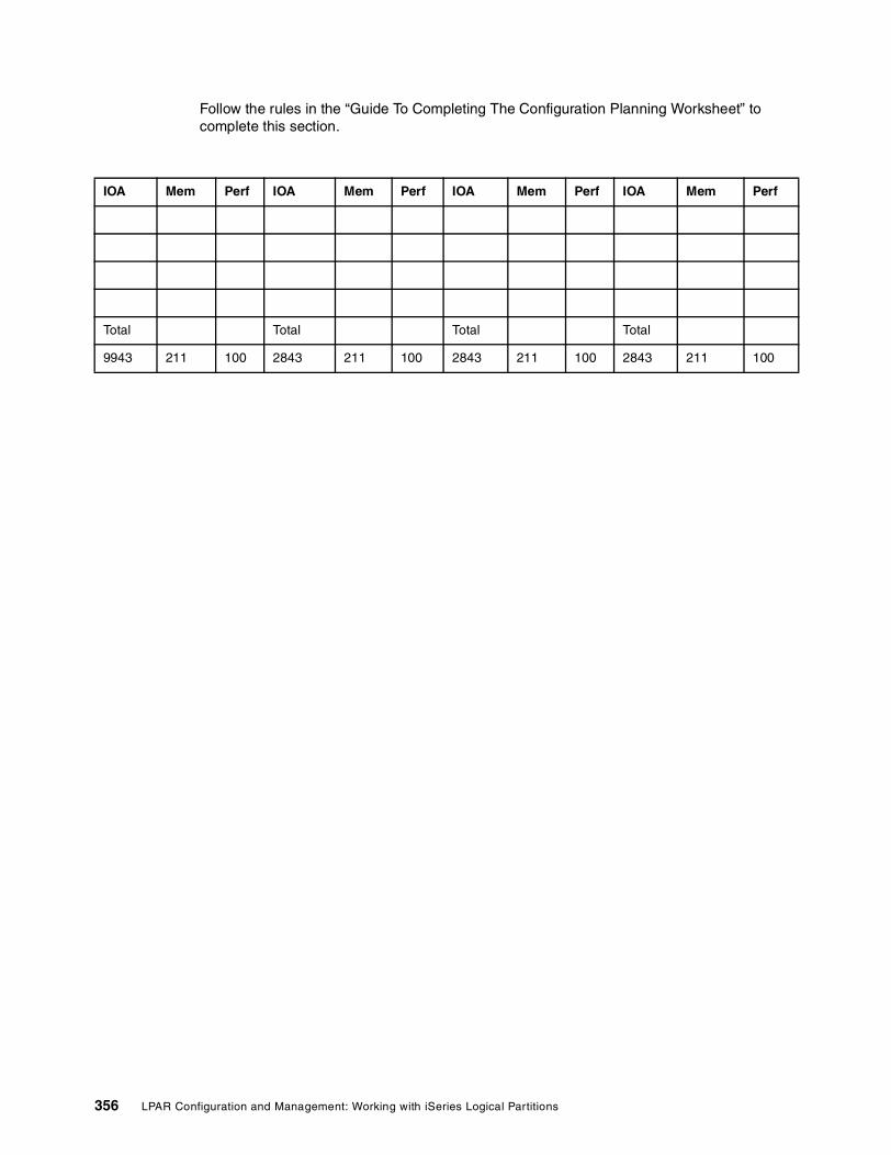
Follow the rules in the “Guide To Completing The Configuration Planning Worksheet” to complete this section.
IOA Mem Perf IOA Mem Perf IOA Mem Perf IOA Mem Perf
Total Total Total Total
9943 211 100 2843 211 100 2843 211 100 2843 211 100
356 LPAR Configuration and Management: Working with iSeries Logical Partitions

5074/5079 Expansion Tower
Follow the rules in the “Guide To Completing The Configuration Planning Worksheet” to complete this section.
A 5079 is two 5074s together in one frame. Copy the 5074 page to create a 5079. Identify as 5079#x-001 (bottom) and 5079#x-002 (top). Configure each tower as an individual 5074.
Location Device Partition Description
DB1 Specify disk units to be placed in these disk slotsDB3 is the top set of disks. DB1 is the bottom set on the left. DB2 is the bottom set on the right.
DB2
DB3
D42 Internal Tape / CD-ROM / DVD-RAM
D41 CD-ROM / DVD- RAM
Slot IOP/IOA Partition Description
C15 IOA
C14 IOP/IOA
BUS #
C13 IOA
C12 IOA
C11 IOP/INS
C10 IOA
C09 IOP/IOA
HSL(9691)
C07 IOA
C06 IOA
C05 IOP/INS
C04 IOA BUS #
C03 IOP/IOA
C02 IOA
C01 9943 64M Base IOP IOP (Base)
Appendix A. LPAR planning worksheets 357

IOA Mem Perf IOA Mem Perf IOA Mem Perf IOA Mem Perf
Total Total Total Total
9943 211 100 2843 211 100 2843 211 100 2843 211 100
358 LPAR Configuration and Management: Working with iSeries Logical Partitions

0578/5078 Expansion Tower
Follow the rules in the “Guide To Completing The Configuration Planning Worksheet” to complete this section.
Slot IOP/IOA Partition Description
C15 IOA
C14 IOP/IOA BUS #
C13 IOA
C12 IOA
C11 IOP/INS
C10 IOA
C09 IOP/IOA
HSL(9691)
C07 IOA
C06 IOA
C05 IOP/INS
C04 IOA BUS #
C03 IOP/IOA
C02 IOA
C01 IOP
IOA Mem Perf IOA Mem Perf IOA Mem Perf IOA Mem Perf
Total Total Total Total
2843 211 100 2843 211 100 2843 211 100 2843 211 100
Appendix A. LPAR planning worksheets 359

5075 Expansion Tower
Follow the rules in the “Guide To Completing The Configuration Planning Worksheet” to complete this section.
Location Device Partition Description
DB1 6 disk units can be placed in these disk slots
Slot IOP/IOA Partition Description
C08 IOA (Short) BUS #
C07 IOP/IOA
C06 IOA
C05 IOP/INS
C04 IOA BUS #
C03 IOP/IOA
C02 IOP/IOA/INS
C01 IOA/SCSI
EMBEDDED 284B 32M IOP IOP (Base)
IOA Mem Perf IOA Mem Perf IOA Mem Perf IOA Mem Perf
Total Total Total Total
284B 100 100 2843 211 100 2843 211 100 2843 211 100
360 LPAR Configuration and Management: Working with iSeries Logical Partitions

5033/5034/5035 Migration TowerBus#
Follow the rules in the “Guide To Completing The Configuration Planning Worksheet” to complete this section.
Location Device Partition Description
L01 to L05F01 to F05F11 to F15
Load source disk in L01. Specify other disk units
D01
D02
Slot IOP/IOA Description
C11
C10
C09
C08
C07 Reserved for INS Bridge card
C06 Reserved for INS Processor
C051 These slots will belong to the MFIOP if an INS is installed
C041
C03 CFIOP
C02
C01
Note 1: Be careful with these slots. The default ownership is with the IOP in slot C03, unless there is an Integrated NetFinity server installed in slots C06-C07. Then they are controlled by the MFIOP.
Appendix A. LPAR planning worksheets 361

5077 Migration Tower (SPD)Bus#
Follow the rules in the “Guide To Completing The Configuration Planning Worksheet” to complete this section.
Location Device Partition Description
11A + 11B Up to 20 disk units
13A + 13B
K01 to K16
D01
D02
D03
D04
Slot IOP/IOA Partition Description
S02S03
671A
S04
S05
S06
362 LPAR Configuration and Management: Working with iSeries Logical Partitions

9364/5064 Migration Tower (PCI) With PCI Cage #9329/#9330 (extension to 5034/5035)
Bus#
Location Device Partition Description
F31 to F35 Specify disk units to be placed in these disk slots
F41 to F451
F51 to F551
D11 Internal media slots. To use these, a 7130 must be ordered for this expansion unit
D12
D13
Slot IOP/IOA Partition Description
E20 Reserved for INS Bridge card
E19 Reserved for INS Processor
E18 Only used if INS installed
E17 Only used if INS installed
E16 Disk IOA slot
E15 2 PCI Controller Card
E14
E13
E12
E11 High speed slot
E10 CFIOP (2809 or 2824)
E09
E08
E07
E06 High speed slot
E05 CFIOP (2809 or 2824)
Appendix A. LPAR planning worksheets 363

Follow the rules in the “Guide To Completing The Configuration Planning Worksheet” to complete this section.
E04
E03
E02
Notes:
1. A 7128 is required to place disks in these slots
2. The Base IOP will be a 2809 for a 9329, or a 2824 for a 9330. Shaded areas indicate base hardware with the expansion unit.
364 LPAR Configuration and Management: Working with iSeries Logical Partitions

9364/5064 Migration Tower (SPD) With SPD Cage #9331 (extension to 5034/5035)
Bus#
Follow the rules in the “Guide To Completing The Configuration Planning Worksheet” to complete this section.
Location Device Partition Description
F31 - F35F41 - F451
F51 - F551
Specify disk units to be placed in these disk slots
D13 Internal media slots. To use these, a 7130 must be ordered for this expansion unit
D12
D11
Slot IOP/IOA Partition Description
S01 Disk IOP if disk is present
S02 Tape IOP if tape is present
S03
S04
S05
S06
Note 1: A 7128 is required to place disks in these slots.
Appendix A. LPAR planning worksheets 365

PCI System Unit Expansion 5065/5066 (Migration Only)Bus#
Location Device Partition Description
DB3 Up to 15 disk units. Driven by IOA in slot C04
DB2 Up to 15 disk units Driven by IOA in slot C14
DB1 Up to 15 disk units Driven by IOA in slot C09
D41
D42
Slot IOP/IOA Partition Description
C01
C02
C03 Base 2824 Base IOP. Not shown as part of a configuration output
C04 SCSI slot
C05
C06
C07
C08 2824
C09 SCSI slot
C10
C11
C12
C13 2824
C14 SCSI slot
C15
Notes:� If disk units are placed in DB1 OR DB2, then a 5101 must be added to the configuration.� Shaded areas indicate base hardware with the 5065 tower� A 5066 is two 5065s together in one frame. Copy the 5065 page to create a 5066. Identify as
5066#x-001 (bottom) and 5066#x-002 (top). Configure each tower as an individual 5065.
366 LPAR Configuration and Management: Working with iSeries Logical Partitions

SPD System Unit Expansion 5072/5073 (Migration Only)Bus#
Follow the rules in the “Guide To Completing The Configuration Planning Worksheet” to complete this section.
Location Device Partition Description
D01 to D04K01 to K08K09 to K16
Slot IOP/IOA Partition Description
S02 Required if disk slots K01 to K16 in the 5052/5058 are used
S03 Required if internal media slots D01 to D04 used
S04
S05
S06
S07
S08
S09
S10
S11
S12
S13
S14
Appendix A. LPAR planning worksheets 367

SPD System Unit Expansion 5082/5083 (Migrations Only)Bus#
Follow the rules in the “Guide To Completing The Configuration Planning Worksheet” to complete this section.
Slot IOP/IOA Partition Description
S03 Required if disk slots 05A to 15C used
S04 Required if disk slots K01 to K16 used
Location Device Partition Description
05A to 15C Up to 16 disk units
K01 to K16 Up to 16 disk units
368 LPAR Configuration and Management: Working with iSeries Logical Partitions

Additional partition placement information Please note: This is required for Validation.
Primary Partition (0)
Mandatory hardware required in the partition
Disk information for partition
Disk capacity total – (Note: This is total capacity, not usable capacity)
Disk unit protection –
IOP/IOA Feature Code BUS Tower/Slot
Load Source Disk Unit IOP
Console
Alternate IPL Device
Electronic Customer Support
Note: Alternation IPL Device may be switched between partitions
Disk Type Quantity Capacity (GB) Attached by IOP/IOA
BUS Tower/Slot
Appendix A. LPAR planning worksheets 369

Secondary Partition (1) Please note: This is required for Validation.
Mandatory hardware required in the partition
Disk information for partition Disk capacity total – (Note: This is total capacity, not usable capacity)
Disk unit protection –
IOP/IOA Feature Code BUS Tower/Slot
Load Source Disk Unit IOP
Console
Alternate IPL Device
Note: Alternate IPL Device may be switched between partitions
Disk Type Quantity Capacity (GB) Attached by IOP/IOA
BUS Tower/Slot
370 LPAR Configuration and Management: Working with iSeries Logical Partitions

Secondary Partition (2) Please note: This is required for Validation.
Mandatory hardware required in the partition
Disk information for partition Disk capacity total – (Note: This is total capacity, not usable capacity)
Disk unit protection –
IOP/IOA Feature Code BUS Tower/Slot
Load Source Disk Unit IOP
Console
Alternate IPL Device
Note: Alternate IPL Device may be switched between partitions
Disk Type Quantity Capacity (GB)
Attached by IOP/IOA
BUS Tower/Slot
Appendix A. LPAR planning worksheets 371
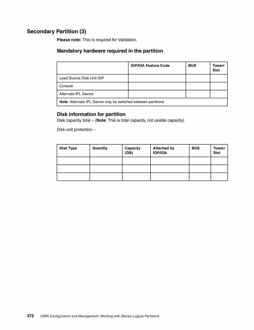
Secondary Partition (3) Please note: This is required for Validation.
Mandatory hardware required in the partition
Disk information for partition Disk capacity total – (Note: This is total capacity, not usable capacity)
Disk unit protection –
IOP/IOA Feature Code BUS Tower/Slot
Load Source Disk Unit IOP
Console
Alternate IPL Device
Note: Alternate IPL Device may be switched between partitions
Disk Type Quantity Capacity (GB)
Attached by IOP/IOA
BUS Tower/Slot
372 LPAR Configuration and Management: Working with iSeries Logical Partitions

Secondary Partition (4) Please note: This is required for Validation.
Mandatory hardware required in the partition
Disk information for partition Disk capacity total – (Note: This is total capacity, not usable capacity)
Disk unit protection –
IOP/IOA Feature Code BUS Tower/Slot
Load Source Disk Unit IOP
Console
Alternate IPL Device
Note: Alternate IPL Device may be switched between partitions
Disk Type Quantity Capacity(GB)
Attached by IOP/IOA
BUS Tower/Slot
Appendix A. LPAR planning worksheets 373

Secondary Partition (5) Please note: This is required for Validation.
Mandatory hardware required in the partition
Disk information for partition Disk capacity total – (Note: This is total capacity, not usable capacity)
Disk unit protection –
IOP/IOA Feature Code BUS Tower/Slot
Load Source Disk Unit IOP
Console
Alternate IPL Device
Note: Alternate IPL Device may be switched between partitions
Disk Type Quantity Capacity (GB)
Attached by IOP/IOA
BUS Tower/Slot
374 LPAR Configuration and Management: Working with iSeries Logical Partitions

AS/400e Servers
(7xx, 6xx, Sxx)
Logical Partitions
Configuration Planning Worksheet
for
Completed on:
Completed by:
E-mail Address:
Validated on:
Validated by:
E-mail Address:
Note: All three sections must be completed before being submitted to IBM for validation.
Appendix A. LPAR planning worksheets 375
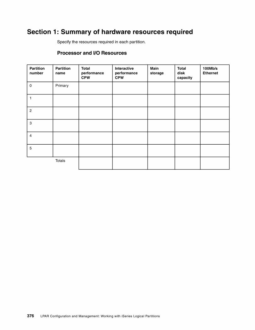
Section 1: Summary of hardware resources requiredSpecify the resources required in each partition.
Processor and I/O Resources
Partition number
Partitionname
Total performance CPW
Interactive performance CPW
Main storage
Totaldisk capacity
100Mb/sEthernet
0 Primary
1
2
3
4
5
Totals
376 LPAR Configuration and Management: Working with iSeries Logical Partitions

Processor and I/O Resources (cont..)
Partition number
Tapedevices
Token ring & 10Mb/sEthernet
Comms(V.24, X21 etc.)
IntegratedNetfinityServer
TwinaxWs Ctl
Other(CD-ROM, etc.)
0
1
2
3
4
5
Totals
Appendix A. LPAR planning worksheets 377

Additional Information
Partition number
New or existing hardware
Console (Twinax or Ops Console)
Electronic Customer Support (Y, N)
Preferred Disk Unit Capacity(4.19 GB, 8.58 GB, 17.54 GB)
Mirror or RAID
Preferred technology for new hardware (SPD or PCI)
0
1
2
3
4
5
378 LPAR Configuration and Management: Working with iSeries Logical Partitions

Section 2: ConfigurationPlease note: This is required for Validation.
A copy of the configuration will be required to validate the configuration. Please send a .out, .txt or .rtf file of the final configuration along with this worksheet.
Note: .cfr and .wip file types will not be processed.
Appendix A. LPAR planning worksheets 379

Section 3: Schematic of the system configuredPlease note: This is required for Validation.
Create a system schematic� System Model:
� Processor Feature:
� Interactive Feature (7xx only):
� Total CPW:
� Interactive CPW:
� Calculated CPW per processor:
Processor Resources
Partitions Batch CPWof partition
Number ofprocessors
Memory Interactive CPW Percentage*
Virtual OptiConnectYes/No
Partition 0 (Primary)
Partition 1
Partition 2
Partition 3
Partition 4
Partition 5
Total
Note *: Interative CPW cannot be less than 1.5% of the partition’s batch CPW.
380 LPAR Configuration and Management: Working with iSeries Logical Partitions

720 System Unit Please note: This is required for Validation.
� Bus Number: 1
� Bus owned by partition: 0 - primary
� Bus will be dedicated (Y/N):
Slot IOP/IOA/Device Assigned to partition Comments
L01 to L05F01 to F05F11 to F15
Primary*
Load source disk in L01. Specify other disk units
D01
D02 Base CD-ROM No Feature number
C11 Load source IOA
C10
C09 Console and ECS IOA
C08
C07 Reserved for INS Bridge card
C06 Reserved for INS Processor
C051 These slots will belong to the MFIOP if an INS is installed
C041
C03 CFIOP (2809 or 2824)
C02
C01
Note 1 *: These locations cannot be reassigned away from the primary.Note 2: Shaded areas indicate base hardware with the system.Note 3: Be careful with these slots. The default ownership is with the IOP in slot C03, unless there is an Integrated NetFinity server installed in slots C06-C07. Then they are controlled by the MFIOP.
Appendix A. LPAR planning worksheets 381
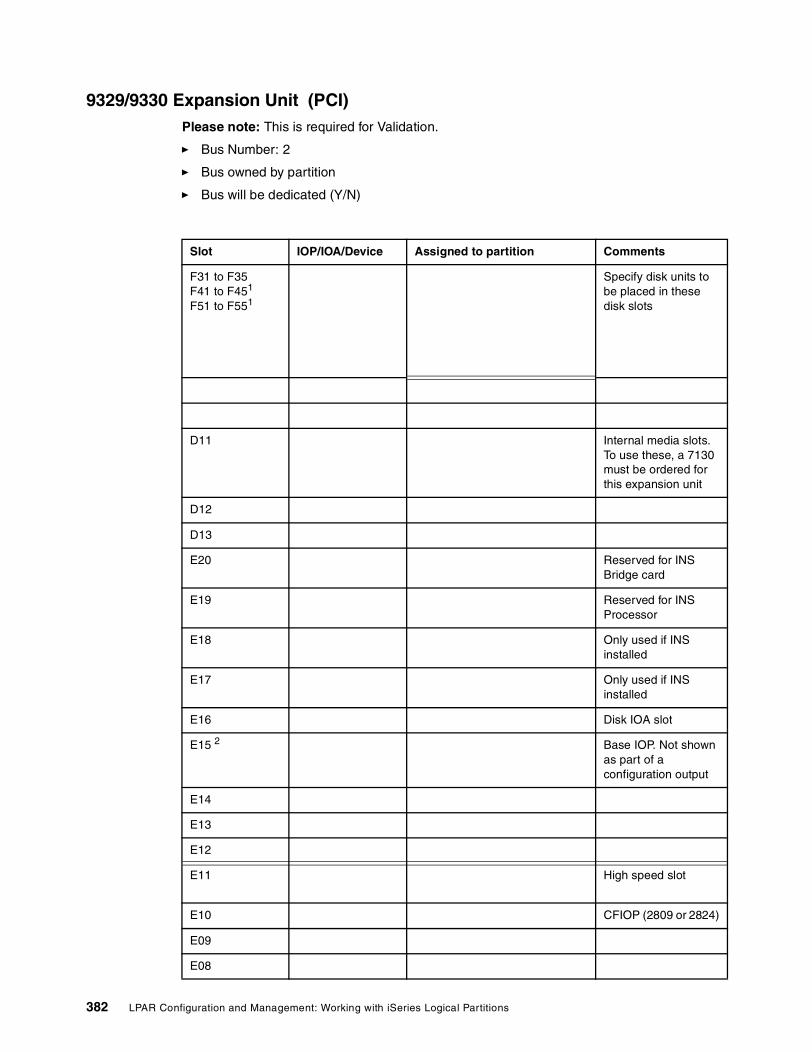
9329/9330 Expansion Unit (PCI) Please note: This is required for Validation.
� Bus Number: 2
� Bus owned by partition
� Bus will be dedicated (Y/N)
Slot IOP/IOA/Device Assigned to partition Comments
F31 to F35F41 to F451
F51 to F551
Specify disk units to be placed in these disk slots
D11 Internal media slots. To use these, a 7130 must be ordered for this expansion unit
D12
D13
E20 Reserved for INS Bridge card
E19 Reserved for INS Processor
E18 Only used if INS installed
E17 Only used if INS installed
E16 Disk IOA slot
E15 2 Base IOP. Not shown as part of a configuration output
E14
E13
E12
E11 High speed slot
E10 CFIOP (2809 or 2824)
E09
E08
382 LPAR Configuration and Management: Working with iSeries Logical Partitions

E07
E06 High speed slot
E05 CFIOP (2809 or 2824)
E04
E03
E02
Note 1: A 7128 is required to place disks in these slots.Note 2: The Base IOP will be a 2809 for a 9329, or a 2824 for a 9330.Note 3: Shaded areas indicate base hardware with the expansion unit.
Appendix A. LPAR planning worksheets 383

9331 Expansion Unit (SPD)Please note: This is required for Validation.
� BUS Number: 2
� Bus owned by partition
� Bus will be dedicated (Y/N)
Slot IOP/IOA/Device Assigned to partition Comments
F31 - F35F41 - F451
F51 - F551
Specify disk units to be placed in these disk slots
D13 Internal media slots. To use these, a 7130 must be ordered for this expansion unit
D12
D11
S01 Disk IOP if disk is present
S02 Tape IOP if tape is present
S03
S04
S05
S06
Note: A 7128 is required to place disks in these slots.
384 LPAR Configuration and Management: Working with iSeries Logical Partitions

730 System UnitPlease note: This is required for Validation.
� BUS Number: 1
� Bus owned by partition: 0 - primary
� Bus will be dedicated (Y/N)
Slot IOP/IOA/Device Assigned to partition Comments
L01 to L04Primary*
Load Source + up to 19 disk units
F01 to F08
K01 to K08
D01 Base CDROM Primary* No feature code
D02 Primary*
S01S02
MFIOP Slot C # Slot B # Slot A #
Primary*9754
WS CTLECS
S03 Alt IPL slot
S04
S05
Note 1* : These locations cannot be reassigned away from the primary.Note 2 : Shaded areas indicate base hardware with the system.
Appendix A. LPAR planning worksheets 385

740 System Unit (with base 9251)Please note: This is required for Validation.
� BUS Number: 1
� Bus owned by partition: 0 - primary
� Bus will be dedicated (Y/N)
Slot IOP/IOA/Device Assigned to partition Comments
11A + 11BPrimary*
Load Source + up to 19 disk units
13A + 13B
K01 to K16
D01 Primary*
D02 Base CDROM Primary* No feature code
D03 Driven by IOP in slot S04
D04
S02S03
MFIOP Slot C # Slot B # Slot A #
Primary* 9754
WS CTLECS
S04 Alt IPL slot **
S05
S06
Note *: These locations cannot be reassigned away from the primary.Note **: If using a 2624 to control a CDROM in slots D03 or D04, do not specify an external ALT IPL resource in the configurator or the order will fail in manufacturing.Note 3: Shaded areas indicate base hardware with the system.
386 LPAR Configuration and Management: Working with iSeries Logical Partitions

PCI System Unit Expansion 5065/5066Please note: This is required for Validation.
� BUS Number
� Bus owned by partition
� Bus will be dedicated ( Y/N )
Slot IOP/IOA/ Device
Assigned to partition Comments
DB3 Up to 15 disk units. Driven by IOA in slot C04
DB2 Up to 15 disk units Driven by IOA in slot C14
DB1 Up to 15 disk units Driven by IOA in slot C09
D41
D42
C01
C02
C03 Base 2824 Base IOP. Not shown as part of a configuration output
C04 SCSI slot
C05
C06
C07
C08 2824
C09 SCSI slot
C10
C11
C12
C13 2824
C14 SCSI slot
C15
Note1: *If disk units are placed in DB1 or DB2, then a 5101 must be added to the configuration.Note 2: Shaded areas indicate base hardware with the 5065 tower.Note 3: A 5066 is comprised of two 5065s. Each one must be configured separately.
Appendix A. LPAR planning worksheets 387

SPD System Unit Expansion 5072/5073Please note: This is required for Validation.
� BUS Number
� Bus owned by partition
� Bus will be dedicated (Y/N)
Slot IOP/IOA/Device Assigned to partition Comments
D01 to D04
S02 Required if disk slots K01 to K16 in the 5052/5058 are used
S03 Required if internal media slots D01 to D04 used
S04
S05
S06
S07
S08
S09
S10
S11
S12
S13
S14
388 LPAR Configuration and Management: Working with iSeries Logical Partitions

SPD System Expansion Unit 5082/5083Please note: This is required for Validation.
� BUS Number
� Bus owned by partition
� Bus will be dedicated (Y/N)
Slot IOP/IOA/Device Assigned to partition Comments
S03 Required if disk slots 05A to 15C used
S04 Required if disk slots K01 to K16 used
05A to 15C Up to 16 disk units
K01 to K16 Up to 16 disk units
Appendix A. LPAR planning worksheets 389

Additional partition placement information Please note: This is required for Validation.
Primary Partition (0)
Mandatory hardware required in the partition
Disk information for partition Disk capacity total – (Note: This is total capacity, not usable capacity)
Disk unit protection –
IOP/IOA Feature Code BUS Slot
Load Source Disk Unit IOP 1
Console 1
Alternate IPL Device 1
Electronic Customer Support 1
Note: Alternate IPL Device may be switched between partitions
Disk type Quantity Capacity (GB) Attached by IOP/IOA BUS Slot
390 LPAR Configuration and Management: Working with iSeries Logical Partitions

Secondary Partition (1) Please note: This is required for Validation.
Mandatory hardware required in the partition
Disk information for partition Disk capacity total – (Note: This is total capacity, not usable capacity)
Disk unit protection –
IOP/IOA Feature Code BUS Slot
Load Source Disk Unit IOP
Console
Alternate IPL Device
Note: Alternate IPL Device may be switched between partitions
Disk type Quantity Capacity (GB) Attached by IOP/IOA BUS Slot
Appendix A. LPAR planning worksheets 391

Secondary Partition (2) Please note: This is required for Validation.
Mandatory hardware required in the partition
Disk information for partition Disk capacity total – (Note: This is total capacity, not usable capacity)
Disk unit protection –
IOP/IOA Feature Code BUS Slot
Load Source Disk Unit IOP
Console
Alternate IPL Device
Note: Alternate IPL Device may be switched between partitions
Disk type Quantity Capacity (GB) Attached by IOP/IOA BUS Slot
392 LPAR Configuration and Management: Working with iSeries Logical Partitions

Secondary Partition (3) Please note: This is required for Validation.
Mandatory hardware required in the partition
Disk information for partition Disk capacity total – (Note: This is total capacity, not usable capacity)
Disk unit protection –
IOP/IOA Feature Code BUS Slot
Load Source Disk Unit IOP
Console
Alternate IPL Device
Note: Alternate IPL Device may be switched between partitions
Disk type Quantity Capacity (GB) Attached by IOP/IOA BUS Slot
Appendix A. LPAR planning worksheets 393

Secondary Partition (4) Please note: This is required for Validation.
Mandatory hardware required in the partition
Disk information for partition Disk capacity total – (Note: This is total capacity, not usable capacity)
Disk unit protection –
IOP/IOA Feature Code BUS Slot
Load Source Disk Unit IOP
Console
Alternate IPL Device
Note: Alternate IPL Device may be switched between partitions
Disk type Quantity Capacity (GB) Attached by IOP/IOA BUS Slot
394 LPAR Configuration and Management: Working with iSeries Logical Partitions

Secondary Partition (5) Please note: This is required for Validation.
Mandatory hardware required in the partition
Disk information for partition Disk capacity total – (Note: This is total capacity, not usable capacity)
Disk unit protection –
IOP/IOA Feature Code BUS Slot
Load Source Disk Unit IOP
Console
Alternate IPL Device
Note: Alternate IPL Device may be switched between partitions
Disk type Quantity Capacity (GB) Attached by IOP/IOA BUS Slot
Appendix A. LPAR planning worksheets 395

396 LPAR Configuration and Management: Working with iSeries Logical Partitions

Appendix B. System reference codes (SRCs) and messages
This appendix offers diagnostic information that is meant to assist in troubleshooting problems in a partitioned system. It covers these topics:
� “Logical partition error messages” on page 404� “Messages in the error report” on page 419
B
© Copyright IBM Corp. 2002 397

System reference codesThe following list contains the common SRCs that the PAL could report. Suggested corrective actions follow each SRC. If an SRC is not listed, it may not be related to logical partitions. You should consult you troubleshooting documentation or your next level of service.
B2pp 1230 (pp equals the partition ID)Cause: The secondary partition could not perform the IPL. The IPL is ended. An example of what causes this SRC to appear is not assigning the correct amount of processors or memory to a secondary partition.
Recovery: From the Work With System Partitions display, correct the configuration problem based on the reason code and then retry the secondary partition’s IPL. If it continues to fail, contact your service provider.
Problem analysis procedure: Identify the reason code from word 3 of the SRC. Possible reason code values are:
� 000000A2: Insufficient amount of interactive performance� 000000A3: Insufficient number of processors� 000000A4: Insufficient main storage size
For any other reason code, contact your service provider.
B2pp 1310 (pp equals the partition ID)Cause: No alternate (D-mode) IPL device IOP selected. The IPL will attempt to continue, but there may not be enough information to find the correct D-mode load source.
Recovery: Go to the Work With System Partitions display and configure an alternate IPL IOP for the secondary partition. Then, retry the secondary partition IPL. If it continues to fail, contact your service provider.
Problem analysis procedure: Collect the detailed hexadecimal data from the product activity log (PAL) for this problem for your service provider.
B2pp 1320 (pp equals the partition ID)Cause: No default load source IOP selected for an A-mode or a B-mode IPL. The IPL will attempt to continue, but there may not be enough information to find the correct load source.
Recovery: Go to the Work With System Partitions display and configure a load source IOP for the secondary partition. Then, retry the secondary partition IPL. If it continues to fail, contact your service provider.
Problem analysis procedure: Collect the detailed hexadecimal data from the product activity log (PAL) for this problem for your service provider.
B2pp 3110 (pp equals the partition ID)Cause: All load source candidates have been scanned for valid secondary partition code.
However, in all cases, errors were encountered that prevented each from being used as a load source candidate for the IPL. The IPL is ended.
Recovery: Address each problem found and then retry the secondary partition’s IPL. If it continues to fail, contact your service provider.
398 LPAR Configuration and Management: Working with iSeries Logical Partitions

Problem analysis procedure: Scan the secondary partition’s SRC history list for prior B2ppxxxx failure SRCs to pinpoint the source of the problem.
B2pp 3125 (pp equals the partition ID)Cause: Memory allocation for early IPL objects failed. The primary is low on memory. The IPL sequence will be retried to the same device.
Recovery: If the primary partition does not have enough main storage, remove some main storage from one or more secondary partitions and then add it to the primary partition. If the primary partition has enough main storage, retry the IPL. If it continues to fail, contact your service provider.
Problem analysis procedure: Ensure that the primary partition has an adequate amount of main storage available to perform the IPL of the secondary partition.
B2pp 3200 (pp equals the partition ID)Cause: The command (Initiate Self Load) sent to the IOP telling it to locate the selected load source device and load or reset itself has failed. The IPL will attempt to continue, and depending on the type of failure, the load source device may be retried or skipped.
Recovery: Look for SRCs in the PAL relating to the device location specified in words 3 through 6. Follow the recovery actions for problems found. Then, retry the secondary partition IPL. If it continues to fail, contact your service provider.
Problem analysis procedure: The values for words 3 through 6 are:
� Word 3: Bus address information� Word 4: Board address information� Word 5: Card address information� Word 6: Unit address information
These values can help you to identify the hardware that caused the error.
B2pp 5106 (pp equals the partition ID)Cause: Creation of main storage dump-temporary segment has failed. An example of what causes this failure is running out of memory in the primary partition. The IPL will be retried to the same device unit address, under the assumption that this is a temporary condition.
Recovery: If the primary partition does not have enough main storage, remove some main storage from one or more secondary partitions and then add it to the primary partition. If the primary partition has enough main storage, retry the IPL. If it continues to fail, contact your service provider.
Problem analysis procedure: Ensure that the primary partition has an adequate amount of main storage available to perform the IPL of the secondary partitions.
B2pp 5117 (pp equals the partition ID)Cause: An MSD or CPM IPL has occurred, but the current information cannot be written to the load source device because a valid dump already exists. The current MSD or CPM information is lost, and the IPL is ended.
Recovery: Perform the IPL of the secondary partition past Dedicated Service Tools (DST) to invalidate the old MSD or CPM information on the load source. Then, subsequent MSD or CPM dumps can be saved.
Appendix B. System reference codes (SRCs) and messages 399

Problem analysis procedure: Identify the partition that has the problem through the partition identification number (pp) given in the SRC.
B2pp 6015 (pp equals the partition ID)Cause: Getting the partition’s load data area failed. The IPL will attempt to continue by skipping this device, and trying a subsequent load source candidate device.
Recovery: This is likely a problem with the load source media being corrupt or invalid. A re-installation of the Licensed Internal Code of the secondary partition is probably required to recover. If it continues to fail, contact your service provider.
Problem analysis procedure: Collect the detailed hexadecimal data from the PAL for this problem for your service provider.
B2pp 6025 (pp equals the partition ID)Cause: Invalid memory for loading into the load ID. The IPL will attempt to continue by skipping this load source device candidate and trying the next candidate.
Recovery: This is likely a problem with the load source media being corrupt or invalid. A re-installation of the Licensed Internal Code of the secondary partition is probably required to recover. If it continues to fail, contact your service provider.
Problem analysis procedure: Collect the detailed hexadecimal data from the PAL for this problem for your service provider.
B2pp 6027 (pp equals the partition ID)Cause: A low memory condition in the primary partition is the most likely cause of this SRC. The entire IPL sequence to the same unit address will be retried.
Recovery: If the primary partition does not have enough main storage, remove some main storage from one or more secondary partitions and then add it to the primary partition. If the primary partition has enough main storage and there are no memory leaks, retry the operation.
Problem analysis procedure: Ensure that the partition was allocated enough main storage, verify that no memory leaks are present, and then retry the operation.
B2pp 7115 (pp equals the partition ID)Cause: Removing an IOP hardware driver (not the load source for the current IPL) from the primary partition failed. The IPL will continue, but the secondary partition will most likely not be able to establish connections to this IOP.
Recovery: You may need to perform another IPL of the secondary partition to recover the specified IOP for use by the secondary partition. If it continues to fail, contact your service provider.
Problem analysis procedure: Identify the values for words 3 through 5 to determine the cause of the error. The values for the words are as follows:
� Word 3: Bus address information� Word 4: Board address information� Word 5: Card address information
400 LPAR Configuration and Management: Working with iSeries Logical Partitions
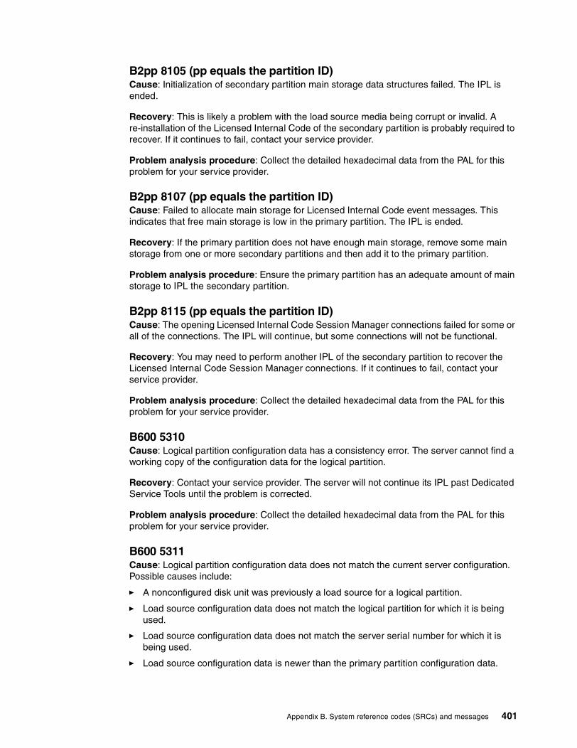
B2pp 8105 (pp equals the partition ID)Cause: Initialization of secondary partition main storage data structures failed. The IPL is ended.
Recovery: This is likely a problem with the load source media being corrupt or invalid. A re-installation of the Licensed Internal Code of the secondary partition is probably required to recover. If it continues to fail, contact your service provider.
Problem analysis procedure: Collect the detailed hexadecimal data from the PAL for this problem for your service provider.
B2pp 8107 (pp equals the partition ID)Cause: Failed to allocate main storage for Licensed Internal Code event messages. This indicates that free main storage is low in the primary partition. The IPL is ended.
Recovery: If the primary partition does not have enough main storage, remove some main storage from one or more secondary partitions and then add it to the primary partition.
Problem analysis procedure: Ensure the primary partition has an adequate amount of main storage to IPL the secondary partition.
B2pp 8115 (pp equals the partition ID)Cause: The opening Licensed Internal Code Session Manager connections failed for some or all of the connections. The IPL will continue, but some connections will not be functional.
Recovery: You may need to perform another IPL of the secondary partition to recover the Licensed Internal Code Session Manager connections. If it continues to fail, contact your service provider.
Problem analysis procedure: Collect the detailed hexadecimal data from the PAL for this problem for your service provider.
B600 5310Cause: Logical partition configuration data has a consistency error. The server cannot find a working copy of the configuration data for the logical partition.
Recovery: Contact your service provider. The server will not continue its IPL past Dedicated Service Tools until the problem is corrected.
Problem analysis procedure: Collect the detailed hexadecimal data from the PAL for this problem for your service provider.
B600 5311Cause: Logical partition configuration data does not match the current server configuration. Possible causes include:
� A nonconfigured disk unit was previously a load source for a logical partition.
� Load source configuration data does not match the logical partition for which it is being used.
� Load source configuration data does not match the server serial number for which it is being used.
� Load source configuration data is newer than the primary partition configuration data.
Appendix B. System reference codes (SRCs) and messages 401

Recovery: Perform one of the following tasks:
� If the load source has been replaced inadvertently, return the original and restart the server.
� If the load source is for the primary partition, recover the logical partition configuration data.
� If the specified load source is for a secondary partition, accept the disk as a load source for that secondary partition.
� If the specified disk unit is not configured, clear the nonconfigured load source to use the new disk unit in the server.
� If a load source disk unit has been moved from a server that has logical partitions, but the current server should not have logical partitions, clear all partition configuration data. This will delete all secondary partitions.
� If the load source came from a partitioned server and was inadvertently used to perform a partition IPL, do not take any action. The initialize disk process during installation clears existing configuration data.
The logical partition will not continue its IPL past DST until the problem is corrected with one of the above actions.
Problem analysis procedure: Collect the detailed hexadecimal data from the PAL entry for this problem for your service provider.
B600 5312Cause: Informational indication that the server detected and corrected a configuration data inconsistency on a logical partition without any loss of data.
Recovery: None.
Problem analysis procedure: None unless a significant number of errors occur. Collect the detailed hexadecimal data from the PAL entries for these problems for your service provider.
B600 5313Cause: The server detected a configuration data inconsistency for a logical partition and could not correct it without loss of the last configuration data update.
Recovery: Manually validate configuration data and repeat any missing configuration actions.
Problem analysis procedure: None unless a significant number of errors occur. Collect the detailed hexadecimal data from the PAL entries for these problems for your service provider.
B600 5340Cause: A logical partition is running with less than the requested number of processors.
Recovery: Perform recovery for the processor-specific errors that are logged in the primary partition.
Problem analysis procedure: Check the PAL in the primary partition for SRCs that indicate hardware errors that should be corrected.
B600 5341Cause: A logical partition is running with less than the requested amount of main storage.
402 LPAR Configuration and Management: Working with iSeries Logical Partitions

Recovery: Perform recovery for the main storage-specific errors that are logged in the primary partition.
Problem analysis procedure: Check the PAL in the primary partition for SRCs that indicate hardware errors that should be corrected.
B6005342Cause: A logical partition has an insufficient number of processors. The logical partitions processor minimums could not be satisfied.
Recovery: All resources have been temporarily assigned to the primary. Perform recovery for the processor specific errors that are logged in the primary partition.
Problem analysis procedure: Check the PAL for hardware errors.
B6005343Cause: A logical partition has an insufficient amount of memory. The logical partitions memory minimums could not be satisfied.
Recovery: All resources have been temporarily assigned to the primary. Perform recovery for the memory specific errors that are logged in the primary partition.
Problem analysis procedure: Check the PAL for hardware errors.
B6005344Cause: A logical partition has an insufficient amount of interactive performance. The logical partitions interactive performance minimums could not be satisfied.
Recovery: All resources have been temporarily assigned to the primary. Perform recovery for the interactive performance specific errors that are logged in the primary partition.
Problem analysis procedure: Check the PAL for hardware errors.
B600 5350Cause: A logical partition software version is outside of the supported secondary partition release delta.
Recovery: Perform one of the following actions:
1. Install a supported operating system version in the logical partition that has the problem.
2. Install an operating system version in the primary partition that supports the version in the offending logical partition.
Problem analysis procedure: Display the logical partition release level and check the logical partition release delta.
B600 5380Cause: An unexpected event occurred in the logical partition management code that was recovered.
Recovery: Contact your service provider if a significant number of these errors have occurred.
Problem analysis procedure: Collect the detailed hexadecimal data from the PAL entry for this problem.
Appendix B. System reference codes (SRCs) and messages 403

B600 5390Cause: An unexpected event occurred in the logical partition management code that could not be recovered. Further changes to the logical partition configuration may not be possible.
Recovery: Contact your service provider. The server might not IPL past DST until the problem is corrected.
Problem analysis procedure: Collect the detailed hexadecimal data from the PAL entry for this problem.
Logical partition error messagesIf the server experiences logical partition errors, it will notify you in one of the following ways:
� An error message appears at the bottom of the display.� The Logical Partitioning Error Report display appears on the system console.� Logical partition error messages appear at the bottom of the display.
This list contains error messages that are specific to logical partitions. These messages generally appear near the bottom of the display. The following list introduces each error message and offers a reason why the error occurred. Recovery actions, if appropriate, are included.
� A console resource must be selected before an alternate console resource
You need to select the main console resource before you can proceed with selecting the alternate console resource. Main and alternate consoles can be the same resource.
� Accept load source disk unit failed
An internal error has occurred in the logical partition configuration manager during a configuration data recovery action. Contact your service provider.
� Accept load source disk unit failed - no data found
No logical partition configuration data exists. No one has altered the server yet by removing resources from the primary partition and assigning them to new secondary partitions. The server did not perform the requested action.
� Accept load source disk unit not performed - data not protected
The server does not detect a problem with the logical partition configuration data saved on this partition’s load source disk unit. There is no reason to perform the accept operation.
� Activate remote service failed
The panel task has experienced a failure. Try the request again. If it continues to fail, contact your service provider.
� Add I/O resource failed
An internal error occurred. The server did not find the IOP you are adding as an available resource. It is not currently allocated to the relevant partition. Contact your service provider.
� Adjust configuration values when changing to OS/400.
This message is informational only.
� Alternate console IOP selection failed
An internal error occurred. The server could not correlate the IOP with the list of resources that are assigned to the partition. Check the Licensed Internal Code logs for a 0C00 C9FF entry.
404 LPAR Configuration and Management: Working with iSeries Logical Partitions
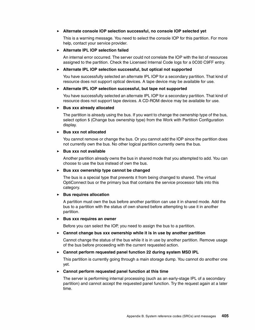
� Alternate console IOP selection successful, no console IOP selected yet
This is a warning message. You need to select the console IOP for this partition. For more help, contact your service provider.
� Alternate IPL IOP selection failed
An internal error occurred. The server could not correlate the IOP with the list of resources assigned to the partition. Check the Licensed Internal Code logs for a 0C00 C9FF entry.
� Alternate IPL IOP selection successful, but optical not supported
You have successfully selected an alternate IPL IOP for a secondary partition. That kind of resource does not support optical devices. A tape device may be available for use.
� Alternate IPL IOP selection successful, but tape not supported
You have successfully selected an alternate IPL IOP for a secondary partition. That kind of resource does not support tape devices. A CD-ROM device may be available for use.
� Bus xxx already allocated
The partition is already using the bus. If you want to change the ownership type of the bus, select option 5 (Change bus ownership type) from the Work with Partition Configuration display.
� Bus xxx not allocated
You cannot remove or change the bus. Or you cannot add the IOP since the partition does not currently own the bus. No other logical partition currently owns the bus.
� Bus xxx not available
Another partition already owns the bus in shared mode that you attempted to add. You can choose to use the bus instead of own the bus.
� Bus xxx ownership type cannot be changed
The bus is a special type that prevents it from being changed to shared. The virtual OptiConnect bus or the primary bus that contains the service processor falls into this category.
� Bus requires allocation
A partition must own the bus before another partition can use it in shared mode. Add the bus to a partition with the status of own shared before attempting to use it in another partition.
� Bus xxx requires an owner
Before you can select the IOP, you need to assign the bus to a partition.
� Cannot change bus xxx ownership while it is in use by another partition
Cannot change the status of the bus while it is in use by another partition. Remove usage of the bus before proceeding with the current requested action.
� Cannot perform requested panel function 22 during system MSD IPL
This partition is currently going through a main storage dump. You cannot do another one yet.
� Cannot perform requested panel function at this time
The server is performing internal processing (such as an early-stage IPL of a secondary partition) and cannot accept the requested panel function. Try the request again at a later time.
Appendix B. System reference codes (SRCs) and messages 405

� Cannot perform requested panel function, partition must be in manual mode
This error occurs if you attempt to use option 10 on the Work with Partition Status display on a partition that is not set to manual mode. To perform option 10, first set the partition to manual mode and restart the partition.
� Cannot perform requested panel function while system is in secure mode
This error occurs if you attempt to use panel functions on the Work with Partition Status display on a secondary partition set to secure mode. When a secondary partition is set to secure mode, you can only perform its panel functions from the primary partition Work with Partition Status display from a DST console. When you change a secondary partition mode from secure to another mode, you can use panel functions on that secondary partition.
� Cannot use reserved primary partition name
You tried to use the word “PRIMARY” for the name of a secondary partition. This name is reserved for the primary partition only. Enter a different name.
� Change bus ownership type failed
The information on the server indicates that the partition does not own or use the bus, so the change ownership type has failed. Refresh the list of resources by exiting and entering the screen again. Try the request again if logical partition really owns or uses the bus. If the request fails again, contact your service provider.
� Change operating environment failed - partition must be powered off
Some logical partition actions require a partition to be powered on or off.
� Change operating environment was cancelled
A user manually cancelled the change to the operating environment. This message is informational only.
� Change operating environment was successful
This message is informational only.
� Change successful, but SLIC release does not support shared processors
This function is not supported for one of the following reasons:
The version or release of the operating system does not support this function or the installed guest operating system does not support this function.
� Clear configuration data failed
An internal error has occurred in the logical partition configuration manager during a configuration data recovery action. Contact your service provider.
� Clear configuration data failed - no data found
No logical partition configuration data exists. No one has altered the server yet by removing resources from the primary and assigning them to new secondary partitions. The server did not perform the requested action.
� Clear non-configured disk unit configuration data failed
An internal error has occurred in the logical partition configuration manager during a configuration data recovery action. Contact your service provider.
� Clear non-configured disk unit configuration data failed - no data found
No logical partition configuration data exists. No one has altered the server yet by removing resources from the primary and assigning them to new secondary partitions, or the disk unit does not contain any configuration data. The server did not perform the requested action.
406 LPAR Configuration and Management: Working with iSeries Logical Partitions

� Clear non-reporting logical partitioning resources failed
An internal error has occurred in the logical partition configuration manager during a configuration data recovery action. Contact your service provider.
� Clear non-reporting resources failed - no data found
No logical partition configuration data exists. No one has altered the server yet by removing resources from the primary partition and assigning them to new secondary partitions. The server did not perform the requested action.
� Clear non-reporting resources not performed - data protected
The server detected logical partition configuration data problems, so the copy operation cannot proceed. You must perform some other recovery action first. See iSeries Backup and Recovery V5R1, SC41-5304, to find out what recovery action to perform.
� Clear reference code history failed
Try the task again. If it continues to fail, contact your service provider.
� Configuration change successful, but partition will not be functional
The server will allow changes made to the logical partition. However, the logical partition might not restart successfully since it does not meet minimum requirements for processors, main storage, or interactive performance. Add the required resources before restarting the partition.
� Configuration data changed during request, try again
The configuration of the partitions has changed while you were making your request. Wait five minutes and retry the operation. The partition may be restarting or may be finishing its restart process.
� Configuration data errors detected - see Product Activity Log
The logical partition configuration data is protected and cannot be changed until you take corrective action. See the PAL for information. Typically, you must use an option on the Recover Configuration Data display to correct the problem.
� Configuration data found that is newer
The server found logical partition configuration data on other disk units. The data is newer than the data on this partition’s load source disk unit. No other action required.
� Configuration data found that is older
The server found logical partition configuration data on other disk units. The data is older than the data on this partition’s load source disk unit. No other action required.
� Configuration data found that originated from another partition
The server found logical partition configuration data on other disk units. The server has determined that the configuration data originated on another partition. Clear the configuration data for the disk units which are not configured before using them.
� Configuration data found that originated from another system
The server found logical partition configuration data on other disk units. The server has determined that the configuration data originated on another server. Clear the configuration data for the disk units that are not configured before using them.
� Console IOP selection failed
An internal error occurred. The server could not correlate the IOP with the list of resources assigned to the partition. Check the Licensed Internal Code logs for a 0C00 C9FF entry.
� Control panel read failed
Try the task again. If it continues to fail, contact your service provider.
Appendix B. System reference codes (SRCs) and messages 407

� Control panel task failed
The virtual service processor task has failed. The use of control panel functions for secondary partitions may not work from the primary partition. Contact your service provider.
� Control panel update failed
An internal error occurred that caused the panel request to fail. Try again and if the condition persists contact your service provider. There may be a 0C00 C9FF Licensed Internal Code log.
� Copy configuration data to other side failed
An internal error has occurred in the logical partition configuration manager during a configuration data recovery action. Contact your service provider.
� Copy configuration data to other side failed - data not valid
This copy of the logical partition configuration data is corrupt or wrong. Try restarting the partition using the other IPL source. If successful, use this function to copy that configuration data to this IPL source. If you cannot fix the problem, contact your service provider.
� Copy configuration data to other side failed - no data found
No logical partition configuration data exists. No one has altered the server yet by removing resources from the primary partition and assigning them to new secondary partitions. The server did not perform the requested action.
� Copy configuration data to other side not performed - data protected
The server has detected logical partition configuration data problems, so the copy operation cannot proceed. Some other recovery action must be performed first.
� Could not start a service tool
A service function could not be started from the Use Dedicated Service Tools menu. If you are attempting to work with server partitions, this error indicates that another user in the same logical partition is currently working with server partitions using SST.
� CPM or MSD IPL retry failed
The panel task has experienced a failure. Try the request again. If it continues to fail, contact your service provider.
� Data may be incomplete until all partitions are IPLed
The service function has checked if secondary partitions that are represented on the screen where this message appears are all powered on and able to report resources such as I/O adapters and devices. The logical partition configuration manager does not track these types of resources in general. You may only see buses and I/O processors until the partitions are activated.
� Data may be incomplete until partition is IPLed
The logical partition is in a state (powered off, for example) where the logical partition configuration manager cannot know for sure what resources are attached to the bus or buses owned or used by the partition. It is possible some resources have physically moved since the last time the partition restarted successfully. This message is informational. It indicates that the server will not display I/O adapters and devices until you restart the logical partition. Bus resources may have been moved since that last restart.
� Data recovery will not be allowed, return code: xxxxxxxx
This message appears when the server experiences an error during a configuration data recovery process. Contact your service provider.
408 LPAR Configuration and Management: Working with iSeries Logical Partitions

� Deactivate remote service failed
The panel task has experienced a failure. Try the request again. If it continues to fail, contact your service provider.
� Default electronic customer support IOP selection failed
An internal error occurred. The server could not correlate the IOP with the list of resources assigned to the partition. Check the Licensed Internal Code logs for a 0C00 C9FF entry.
� Delete failed - one or more partitions currently use the shared pool
This action is not allowed because there are active secondary partitions using the shared processor pool.
� Detailed report does not exist for the problem
This problem does not have any detailed information about it. No other action is required.
� Disk unit IOP reset/reload failed
The panel task has experienced a failure. Try the request again. If it continues to fail, contact your service provider.
� Display processor status failed, no processors are owned by partition
The selected partition does not have any processors. The requested option cannot be performed.
� DST console session required to use panel function while in secure mode
This error occurs in SST when you select a function that must be performed in DST. Use the DST display to perform this function.
� Dump MFIOP failed
The request to dump the MFIOP failed. Check the product activity log for errors associated with the MFIOP resource and report the errors to your service provider.
� Dump MFIOP was successful
You have successfully dumped the MFIOP.
� Electronic Customer Support IOP selection successful, async not supported
You have successfully selected a default electronic customer support IOP for a secondary partition. Beware that the asynchronous communications protocol is not supported by that kind of resource.
� Electronic Customer Support IOP selection successful, SDLC not supported
You have successfully selected a default electronic customer support IOP for a secondary partition. Beware that the SDLC communications protocol is not supported by that kind of resource.
� Enter value for shared processor pool units
Set the value for the shared processor pool units.
� Force DST failed
The panel task has experienced a failure. Try the request again. If it continues to fail, contact your service provider.
� Function not allowed during system MSD IPL
This partition is currently going through a main storage dump. You cannot perform the requested functions at this time.
Appendix B. System reference codes (SRCs) and messages 409
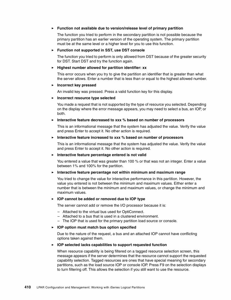
� Function not available due to version/release level of primary partition
The function you tried to perform in the secondary partition is not possible because the primary partition has an earlier version of the operating system. The primary partition must be at the same level or a higher level for you to use this function.
� Function not supported in SST, use DST console
The function you tried to perform is only allowed from DST because of the greater security for DST. Start DST and try the function again.
� Highest number allowed for partition identifier: xx
This error occurs when you try to give the partition an identifier that is greater than what the server allows. Enter a number that is less than or equal to the highest allowed number.
� Incorrect key pressed
An invalid key was pressed. Press a valid function key for this display.
� Incorrect resource type selected
You made a request that is not supported by the type of resource you selected. Depending on the display where the error message appears, you may need to select a bus, an IOP, or both.
� Interactive feature decreased to xxx % based on number of processors
This is an informational message that the system has adjusted the value. Verify the value and press Enter to accept it. No other action is required.
� Interactive feature increased to xxx % based on number of processors
This is an informational message that the system has adjusted the value. Verify the value and press Enter to accept it. No other action is required.
� Interactive feature percentage entered is not valid
You entered a value that was greater than 100 % or that was not an integer. Enter a value between 1% and 100% for the partition.
� Interactive feature percentage not within minimum and maximum range
You tried to change the value for interactive performance in this partition. However, the value you entered is not between the minimum and maximum values. Either enter a number that is between the minimum and maximum values, or change the minimum and maximum values.
� IOP cannot be added or removed due to IOP type
The server cannot add or remove the I/O processor because it is:
– Attached to the virtual bus used for OptiConnect.– Attached to a bus that is used in a clustered environment.– The IOP that is used for the primary partition load source or console.
� IOP option must match bus option specified
Due to the nature of the request, a bus and an attached IOP cannot have conflicting options taken against them.
� IOP selected lacks capabilities to support requested function
When resource capability is being filtered on a tagged resource selection screen, this message appears if the server determines that the resource cannot support the requested capability selection. Tagged resources are ones that have special meaning for secondary partitions, such as the load source IOP or console IOP. Press F9 on the selection displays to turn filtering off. This allows the selection if you still want to use the resource.
410 LPAR Configuration and Management: Working with iSeries Logical Partitions

� I/O resources differ from system, adjust configuration after recovery
This is a warning message. Some resources in the server are not originally part of the configuration. Perform recovery actions for the partition configuration data.
� Insufficient available shared processor units
You have tried to set the number of shared processor units to a number greater than is available in the shared processor pool. Possible solutions are to add more processors to the shared processing pool or to reduce the number of shared processor units to be less than or equal to the number of available shared processors units.
� IPL restart failed
The panel task has experienced a failure. Try the request again. If it continues to fail, contact your service provider.
� Load source and console IOPs will be required to continue with create
There are no available IOPs to add to this partition. Go back and remove the required IOPs from another partition that does not need them and then continue with creating this partition.
� Load source IOP selection failed
An internal error occurred. The server could not correlate the IOP with the list of resources assigned to the partition. Check the Licensed Internal Code logs for a 0C00 C9FF entry.
� Logical partitioning configuration data error detected
Logical partition configuration manager checksum failed. You cannot trust the configuration data to be valid. Contact your service provider.
� Logical partitioning configuration data is not valid
Logical partition configuration management did not detect logical partition data on the current IPL source of the load source disk unit (source A or source B). Contact your service provider.
� Logical partitioning configuration data not found
No logical partition configuration data exists. No one has altered the server yet by removing resources from the primary partition and assigning them to new secondary partitions. The server did not perform the requested action.
� Make a valid selection
You entered input that is not valid for this selection. Enter valid input for this selection.
� Maximum interactive performance set to xxx % based on maximum processors
The server has 100% interactive performance available to split between partitions. However, the allowable ranges for each partition depend on how the server processors are split. For example, if one partition has only 10% of the server’s processors, then it would not be possible for that partition to use 99% of the interactive performance available to the server. These error messages will appear when the interactive performance settings are outside of a practical range, and the server has made the adjustment for you.
� Maximum processor pool units above what maximum processors can support
You have tried to set the amount of processing units to a number greater than the maximum processors can support. A possible solution is to reduce the maximum amount of processing units requested.
� Maximum processor units set to xxx based on maximum processors
The maximum processor units were adjusted based on the maximum processors specified. The adjusted value is different than what was specified to satisfy the maximum processor units supported per processor.
Appendix B. System reference codes (SRCs) and messages 411

� Maximum value entered is not valid
The value you entered is incorrect. Either it is greater than what this server allows, or it is not an integer. Enter a different value.
� Minimum interactive feature set to xxx % based on minimum processors
The server has 100% interactive performance available to split between partitions. However, the allowable ranges for each partition depend on how the server processors are split. For example, if one partition has 90% of the server’s processors, then it would not be possible for that partition to use 1% of the interactive performance available to the server. These error messages will appear when the interactive performance settings are outside of a practical range, and the server has made the adjustment for you.
� Minimum processor pool units below what minimum processors can support
You have tried to set the amount of processing units to a number less than the minimum processors can support. A possible solutions is to increase the amount of processing units requested.
� Minimum processor units set to xxx based on minimum processors
The minimum processor units were adjusted based on the minimum processors specified. The adjusted value is different than what was specified to satisfy the minimum processor units supported per processor.
� Minimum value cannot be greater than the maximum value
The value you specified for the minimum is greater than the value for the maximum. Either make the maximum value greater or enter a value for the minimum that is less than the current maximum.
� Minimum value entered is not valid
The value you entered is incorrect. Either it is less than what this server allows, or it is not an integer. Enter a different value.
� Multiple interactive feature values adjusted based on processor values
This is an informational message that the system has adjusted the values. Verify the values and press Enter to accept them. No other action is required.
� New interactive performance percentage entered is greater than available
Not enough interactive performance is available to allow you to add the amount that you requested. Either add less interactive performance or free the interactive performance from another partition.
� New number of processors entered is greater than available
Not enough processors are available to allow you to add the amount that you requested. Either add fewer processors or free processors from another partition.
� New partition name entered is not valid
The partition name must conform to the following rules: Characters can be any letter (A to Z) and any number (0 to 9). Name cannot be all blanks. Name cannot be PRIMARY. Name cannot be the same as an existing secondary partition.
� New partition name entered is not valid - name already exists
The name you entered for this partition is already being used by another partition on the server. Enter a different name for this partition.
� New size of main storage entered is greater than available
Not enough main storage is available to allow you to add the amount that you requested. Either add less main storage or free the main storage needed from another partition.
412 LPAR Configuration and Management: Working with iSeries Logical Partitions

� No alternate IPL device is currently attached to IOP selected
This is a warning message. The server cannot identify any alternate IPL devices attached to this IOP. If no devices are attached, make sure you attach one before trying to use the IOP in a partition.
� No change made, the new name is the same as the existing name
This is an informational message. You choose to change the name of the partition. However, the name you selected is the same as it was previously. No other action is required.
� No console device is currently attached to IOP selected
This is a warning message. The server cannot identify any console devices attached to this IOP. If no devices are attached, make sure that you attach one before trying to use the IOP in a partition.
� No electronic customer support resource is attached to IOP selected
This is a warning message. The server cannot identify any electronic customer support devices attached to this IOP. If no devices are attached, make sure that you attach one before trying to use the IOP in a partition.
� No guest partitions defined
This is informational only.
� No load source capable disk unit is currently attached to IOP selected
This is a warning message. The server cannot identify any load source disk units attached to this IOP. If no devices are attached, make sure that you attach one before trying to use the IOP in a partition.
� No non-configured disk units found that have configuration data
This message appears on the Select Non-Configured Disk Unit for Configuration Data Clear display. The disk units you selected do not contain any partition configuration data.
� No service printer specified. Print request failed
This message appears in DST or SST when you do not select a printer and exit the prompt. If you meant to select a printer, try the request again.
� Not able to start Work with system partitions
This message appears in SST and indicates that another user on the server is currently working with logical partitions in either DST or SST.
� Not enough interactive performance percentage available
You requested to add more interactive performance than is available. Either add less interactive performance or remove what you need from other partitions.
� Not enough main storage available
You requested to add more main storage than is available. Either add less main storage or remove what you need from other partitions.
� Not enough processors available
You requested to add more processors than are available. Either add fewer processors or remove what you need from other partitions.
� Not enough processors available
There are not enough available processors to complete your request. Reduce the number of processors being requested.
Appendix B. System reference codes (SRCs) and messages 413

� Not enough shared pool processor units available
You tried to set the amount of shared processor units to a number greater than is available. Possible solutions are to add more processors to the shared pool or to reduce the amount of processor units requested to be less than or equal to the amount of processors units that are available.
� Number entered is too small - less than required by using partitions
The shared processor pool requires more processors than the number you entered. Enter a greater number of processors to complete the request. The shared processor pool must have enough processors to support the greatest number of processors of all the partitions using the shared processor pool.
� Number of processors allocated to pool changed successfully
This message is informational only.
� Number of processors entered is greater than available
You tried to move more processors than are available. Reduce the number of processors to move.
� Number of processors not within minimum and maximum range
You tried to change the value for processors in this partition. However, the value you entered is not between the minimum and maximum values. Either enter a number that is between the minimum and maximum values, or change the minimum and maximum values.
� Number of processors entered is not valid
The value you entered is incorrect. Either it is less than or greater than what is allowed for this server or it is not an integer. Enter a different value.
� Number of shared processor units not within minimum and maximum range
The number of processing units must be greater than or equal to the minimum and less than or equal to the maximum shared processor units.
� Only one partition may be selected
You tried to perform an action on more than one partition. This display can only handle one request at a time. Repeat the action separately for each partition.
� Only one resource may be selected
You tried to perform an action on more than one resource. This display can only handle one request at a time. Repeat the action separately for each resource.
� Only one resource of a specific type may be selected
You tried to perform an action on more than one type of resource. This display can only handle one request at a time for each type of resource. Repeat the action separately for each type of resource.
� Option is allowed only from primary partition
You can perform options 13 and 14 to change the System IPL Action from the primary partition. The server does not allow the displaying or changing of that value in secondary partitions. Or the secondary partition is in secure mode. You must, therefore, go to the primary DST console to change the mode to a value other than secure mode.
� Option not allowed during system MSD IPL
When the server is performing a main storage dump (MSD), you cannot perform many of the logical partition configuration options that alter the logical partition configuration data. For example, you cannot perform recovery actions or create a new secondary partition.
414 LPAR Configuration and Management: Working with iSeries Logical Partitions

� Option not allowed for new partition until next system IPL
This partition was recently created. You cannot perform any actions from it until after you restart the server. Once you restart the server, you can attempt this option.
� Option not allowed for primary partition
Some options do not make sense when issued against the primary partition. For example you cannot change the primary partition’s name, delete the primary partition, or select a tagged secondary resource like a load source IOP or a console IOP.
� Option not allowed for resource chosen
The option you entered is not valid on this display. See the display for a list of allowed options.
� Option not allowed while partition is in secure mode, use primary DST
This error occurs if you attempt to use panel functions on the Work with Partition Status display on a partition set to secure mode. When a partition is set to secure mode, you can only perform its panel functions from the primary partition Work with Partition Status display from a DST console. When you change a partition mode from secure to another mode, you can use panel functions on that secondary partition.
� Option is only allowed for the primary partition
Some actions are not allowed for a secondary partitions. For example, configuration changes cannot be made from a secondary partition.
� Panel function failed - keylock is not in control panel
The key for the server is not in the control panel. Insert the key and try the request again.
� Partition already powered off
You selected to power off this partition. However, the partition is already off.
� Partition already powered on
You selected to power on this partition. However, the partition is already on.
� Partition create failed - maximum number of partitions already exist
The server already has the maximum allowed number of logical partitions allowed for the release. You cannot create another one.
� Partition create failed - not enough system resources available
You cannot create another partition. The maximum number of partitions that this server supports have already been created.
� Partition delete failed - partition must be powered off
You cannot delete a partition while it is still powered on. Power off the partition and then perform the delete operation for that partition.
� Partition identifier entered is already in use by another partition
This error occurs when you try to give the partition an identifier that is already used by another partition on the server. Enter a different identifier.
� Partition identifier entered is not valid
You entered an identifier that was not between 1 and 24 or that was not an integer. Enter a value that is between 1 and 24.
Appendix B. System reference codes (SRCs) and messages 415

� Partition install may be needed after recovery due to version/release level
This is a warning message. The system found what appears to be an unsupported software version in one of the secondary partitions. The identified release cannot support the current server hardware. If the secondary partition has an unsupported release, install a supported OS/400 version after you finish recovering the primary partition.
� Partition xxx create successful, but partition will not be functional
The server allowed the changes to the logical partition. However, the logical partition might not restart successfully since it does not meet one or more of the minimum requirements for processors, memory, or interactive performance. Add the required resources before restarting the partition.
� Power off domain failed
The panel task has experienced a failure. Try the request again. If it continues to fail, contact your service provider.
� Power on domain failed
The panel task has experienced a failure. Try the request again. If it continues to fail, contact your service provider.
� Primary partition configuration data recovery failed
An internal error has occurred in the logical partition configuration manager during a configuration data recovery action. Contact your service provider.
� Primary partition configuration data recovery failed - no data found
No logical partition configuration data exists. No one has altered server yet by removing resources from the primary partition and assigning them to new secondary partitions. The server did not perform the requested action.
� Primary partition configuration data recovery failed - no new data found
No further action is necessary. The server did not find any logical partition configuration data on other disk units that is different than what is currently saved on this logical partition’s load source disk unit.
� Print request failed with unknown error
An unknown error has occurred. Contact your service provider.
� Print request not submitted, no entries listed to print
You tried to send a print request without selecting anything to print, or, this display does not allow printing. Try to print from a display that allows you to select entries.
� Print request submitted to service printer with one or more errors
This is an informational error. Although the print request had some errors, the print request was successful. You may want to contact your service provider to determine the nature of the problem.
� Problem resolution failed
A problem selected to be accepted is not currently in the list of known problems for the logical partition, or another internal error occurred. Contact your service representative.
� Problem resolution failed, unable to clear attention errors
A problem selected to be accepted is not currently in the list of known problems for the logical partition, or another internal error occurred. Contact your service representative.
� Problem resolution failed, unable to clear informational errors
A problem selected to be accepted is not currently in the list of known problems for the logical partition, or another internal error occurred. Contact your service representative.
416 LPAR Configuration and Management: Working with iSeries Logical Partitions
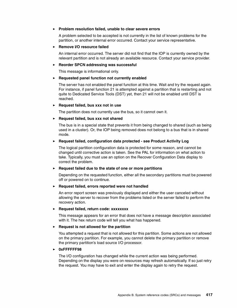
� Problem resolution failed, unable to clear severe errors
A problem selected to be accepted is not currently in the list of known problems for the partition, or another internal error occurred. Contact your service representative.
� Remove I/O resource failed
An internal error occurred. The server did not find that the IOP is currently owned by the relevant partition and is not already an available resource. Contact your service provider.
� Reorder SPCN addressing was successful
This message is informational only.
� Requested panel function not currently enabled
The server has not enabled the panel function at this time. Wait and try the request again. For instance, if panel function 21 is attempted against a partition that is restarting and not quite to Dedicated Service Tools (DST) yet, then 21 will not be enabled until DST is reached.
� Request failed, bus xxx not in use
The partition does not currently use the bus, so it cannot own it.
� Request failed, bus xxx not shared
The bus is in a special state that prevents it from being changed to shared (such as being used in a cluster). Or, the IOP being removed does not belong to a bus that is in shared mode.
� Request failed, configuration data protected - see Product Activity Log
The logical partition configuration data is protected for some reason, and cannot be changed until corrective action is taken. See the PAL for information on what action to take. Typically, you must use an option on the Recover Configuration Data display to correct the problem.
� Request failed due to the state of one or more partitions
Depending on the requested function, either all the secondary partitions must be powered off or powered on to continue.
� Request failed, errors reported were not handled
An error report screen was previously displayed and either the user canceled without allowing the server to recover from the problems listed or the server failed to perform the recovery action.
� Request failed, return code: xxxxxxxx
This message appears for an error that does not have a message description associated with it. The hex return code will tell you what has happened.
� Request is not allowed for the partition
You attempted a request that is not allowed for this partition. Some actions are not allowed on the primary partition. For example, you cannot delete the primary partition or remove the primary partition’s load source I/O processor.
� 0xFFFFFF98
The I/O configuration has changed while the current action was being performed. Depending on the display you were on resources may refresh automatically. If so just retry the request. You may have to exit and enter the display again to retry the request.
Appendix B. System reference codes (SRCs) and messages 417

� Request failed, more processors specified than are in shared pool
You tried to set the amount of processors to a number greater than is available in the shared processor pool. Possible solutions are to add more processors to the shared pool or reduce the amount of processors requested to be less than or equal to the amount of processors that is available.
� Request failed - see Product Activity Log
An internal error has occurred in the logical partition configuration manager during a configuration change request. See the PAL for information. Contact your service provider.
� Resources requested greater than is allocated to the partition
The partition may have been restarted with fewer processors, main storage, or interactive performance than requested (but within the minimum allowable limit). The attempt to remove these resources exceeds what the partition is currently using.
� Size of main storage entered is not valid
The value you entered for the main storage is not a valid integer. Enter an integer.
� Size of main storage not within minimum and maximum range
You tried to change the value for main storage in this partition. However, the value you entered is not between the minimum and maximum values. Either enter a number that is between the minimum and maximum values, or change the minimum and maximum values.
� Shared processor pool create was successful
This message is informational only.
� Shared processor pool delete was successful
This message is informational only.
� Shared processor pool units above maximum processor capacity
You have set the amount of processing units to be more than the maximum processor capacity. A possible solution is to reduce the amount of processing units you are requesting to be less than or equal to the amount the current processors can support. Each processor can support a maximum of 1.00 processing units.
� Shared processor pool unit allocation entered is not valid
The value you entered is incorrect. Either it is greater than or less than what the shared pool allows. Enter a different value.
� Shared processor pool units below minimum processor capacity
You have set the amount of processing units to be less than the minimum processor capacity. A possible solution is to increase the amount of processing units you are requesting.
� Shared processor pool units greater than processors can support
You have specified processing units greater than the processors can support. Possible solutions are use more processors or reduce the number of processor units.
� Smallest minimum main storage size is xxxxxxxx for maximum entered
The server must enforce a range of reasonable values for the minimum and maximum main storage values relative to each other. This is because a certain amount of fixed storage is allocated for server use based on the maximum size specified. The fixed storage required by the server cannot be smaller than the minimum value specified. Adjust your minimum value to be at least as large as the value in the message. Or, adjust the maximum size to some value that is smaller.
418 LPAR Configuration and Management: Working with iSeries Logical Partitions

� System IPL required to activate changes
Changes have been made to the logical partition configuration that require a server restart to activate. Examples are partition create, delete, recovery, bus ownership type change, or changing the primary partition’s processors, main storage, or interactive performance values.
� Unit has incorrect logical partition configuration
The logical partition configuration data is protected for some reason, and cannot be changed until corrective action is taken. See the PAL for information on what action to take. Typically, you must use an option on the Recover Configuration Data display to correct the problem.
� Unknown error in service function
An unexpected condition occurred in the licensed code that either manages the logical partition configuration data or the logical partition service function. Check the Licensed Internal Code logs for a 0C00 C9FF entry. Contact your service provider.
� Update configuration data failed
An internal error has occurred in the logical partition configuration manager during a configuration data recovery action. Contact your service provider.
� Update configuration data failed - no data found
No logical partition configuration data exists. The server has not been altered yet by removing resources from the primary and assigning them to new secondary partitions. The server did not perform the requested action.
� Value entered for Level of detail is not valid
The value you supplied for this field is incorrect. Enter a valid value for the Level of detail.
� Value entered for Number of reference codes is not valid
The value you supplied for this field is incorrect. Enter a valid value for the Number of reference codes.
� Value entered for Secondary partition(s) is not valid
The value you supplied for this field is incorrect. Enter a valid value for the Secondary partition.
� Value entered for System partition(s) is not valid
The value you supplied for this field is incorrect. Enter a valid value for the System partition.
Messages in the error reportThis section explains partitioning message severity and message text.
Logical partition error messages in the error reportWhen the logical partitioning configuration manager must report multiple errors, the Logical Partitioning Error Report display appears. This display contains a summary of errors with details available by using option 5 on the particular error.
From this display, you may cancel the current request and return to the previous display by selecting F3 (Exit) or F12 (Cancel). You can also accept the error and continue by selecting option 1 (Accept problem) or F10 (Accept all problems and continue). However, you should fully understand these errors before taking any actions like option 1 or F10.
Appendix B. System reference codes (SRCs) and messages 419

The report groups error messages by category as follows:
� Informational: A recoverable error occurred that did not prevent the requested operation.
� Attention: An error occurred which prevents the requested operation. Details describe the cause of the failure, but do not tell you which operation failed. See any severe errors to determine which operation failed.
� Severe: An operation could not complete successfully. See any previous attention messages to determine reasons for the failed operation.
The following list gives attention message and severe message summaries, why the error may have occurred, and recommended actions.
Bus not removedA severe message indicating that a bus remove operation failed. Correct previous attention errors listed in the error report and try the operation again.
Bus ownership type change failedA severe message indicating that a change bus ownership type operation failed. Correct previous attention errors listed in the error report and try the operation again.
Device in useAn attention message indicating that a particular resource is in use by the server, its owning IOP, or bus while someone attempted to remove it from a partition. If this resource is a disk unit, you must remove it from its current auxiliary storage pool (ASP) before removing it from the IOP or bus.
� For a disk unit, see the “Working with Auxiliary Storage Pools” chapter in iSeries Backup and Recovery V5R1, SC41-5304, for information on how to remove a disk unit from an ASP.
� For all other resources, perform the following steps:
a. Write down the logical address of the resource that you need to vary off. You can find this information when you display the allocated resources for the partition.
b. From OS/400, use the Work with Configuration Status (WRKCFGSTS) command to find the resource name based on the logical address. From DST, go to Hardware Service Manager.
c. Vary off any devices or controllers that are active on the resource.
IOP not removedThis is a severe message indicating that an IOP remove operation failed. Correct previous attention errors listed in the error report and try the operation again.
IOP requires reallocationThis is an attention message indicating that you attempted to change bus ownership type from shared to dedicated. However, the bus contains IOPs currently unassigned to any logical partition. Add I/O resources to assign the available IOPs to the same partition as the bus owner. Then, repeat the change of bus ownership type.
I/O resource not updatedA severe message indicating that an I/O resource could not be updated in the configuration data. Correct previous attention errors listed in the error report and try the operation again.
420 LPAR Configuration and Management: Working with iSeries Logical Partitions

State of IOP is unknownThis is an attention message indicating a particular IOP cannot be located in the partition from which it is being removed. If the owning partition is currently powered off, you can ignore this error if you know the IOP and its resources are available. If the owning partition is currently powered on, this error may indicate that the owning IOP was recently added to the partition but is not yet active.
Wait five minutes and retry the operation. If the failure persists or if the IOP was not recently added to the owning partition, contact your service representative.
Appendix B. System reference codes (SRCs) and messages 421

422 LPAR Configuration and Management: Working with iSeries Logical Partitions

Appendix C. Sample code
This appendix provides code examples for logical partitioning.
C
© Copyright IBM Corp. 2002 423

Sample programThe following is a sample program for collecting partition information. This information is desirable for a number of reasons, especially when planning for migration, system hardware additions, and new partitions.
H*********************************************************************H* COMPILE THIS PROGRAM WITH DFTACTGRP(*NO) *H* *H* Sample ILE RPG program using the MI instruction MATMATR to *H* materialize partition information on the iSeries (V5R1 Updates) *H*********************************************************************F* F* Print file specifications for output F* FQSYSPRT O F 132 PRINTER F* D* D* Prototype of MI MATMATR instruction D* DMatMAtr PR EXTPROC('_MATMATR1') D * VALUE D 2 CONST D* D* Working variables for Materialize D* DAttribPtr s * inz(%addr(Attributes)) DMatOption s 2 inz(x'01E0') D* D* Receiver variable for Materialize D* DAttributes DS 512 D BytPrv 10i 0 D BytAvl 10i 0 D NumParts 3u 0 D CurPart 3u 0 D PriPart 3u 0 D Reserved 5 D LogSerial 10 D Reserved2 6 D MinProc 5u 0 D MaxProc 5u 0 D CurProc 5u 0 D Reserved3 2 D CfgMinMem 10u 0 D CfgMaxMem 10u 0 D CurAvlMem 10u 0 D MinIntPerf 3u 0 D MaxIntPerf 3u 0 D CurIntPerf 3u 0 D Reserved4 5 D MinProcUnt 10u 0 D MaxProcUnt 10u 0 D CurProcUnt 10u 0 D* D Description S 25 inz(' ') D ValueN S 10 0 inz(0) D ValueN2 S 10 2 inz(0) D ValueC S 10 inz(' ') C*
424 LPAR Configuration and Management: Working with iSeries Logical Partitions

C* Set Bytes Provided to size of Recevier Variable (Attributes C* C eval BytPrv = %size(Attributes) C* C* Use MATMATR MI instruction C* C callp MatMAtr(AttribPtr: MatOption) C* C* Determine if information returned C* C if BytAvl >= 56 C* C* Read though the detail and output it to the printer C* C Except Header C* C* Total number of partitions that have been created C* C eval Description = 'Total Partitions Created' C eval ValueN = NumParts C Except DetailN C* C* Current partition C* C eval Description = 'Current Partition Number' C eval ValueN = CurPart C Except DetailN C* C* Logical Serial Number C* C eval Description = 'Logical Serial Number ' C eval ValueC = LogSerial C Except DetailC C* C* Minimum No Processors C* C eval Description = 'Minimum No Processors ' C eval ValueN2 = MinProcUnt / 100 C Except DetailN2 C* C* Maximum No Processors C* C eval Description = 'Maximum No Processors ' C eval ValueN2 = MaxProcUnt /100 C Except DetailN2 C* C* Current No Processor C* C eval Description = 'Current No Processors 'C eval ValueN2 = CurProcUnt /100 C Except DetailN2 C* C* Minimum Amount Memory C* C eval Description = 'Minimum Amount Memory 'C eval ValueN = CfgMinMem C Except DetailN C* C* Maximum Amount Memory C*
Appendix C. Sample code 425

C eval Description = 'Maximum Amount Memory 'C eval ValueN = CfgMaxMem C Except DetailN C* C* Current Amount Memory C* C eval Description = 'Current Amount Memory 'C eval ValueN = CurAvlMem C Except DetailN C* C* Minimum Interactive Performance C* C eval Description = 'Minimum Interactive Perf'C eval ValueN = MinIntPerf C Except DetailN C* C* Maximum Interactive Performance C* C eval Description = 'Maximum Interactive Perf'C eval ValueN = MaxIntPerf C Except DetailN C* C* Current Interactive Performance C* C eval Description = 'Current Interactive Perf'C eval ValueN = CurIntPerf C Except DetailN C Except End C* C else C eval ValueC = ' ' C eval Description = '****Error Occured****' C Except DetailC C Except End C endif C* C* exit sample program C* C eval *inlr = '1' C return C* OQSYSPRT E 1 HEADER 2 03 O 24 'Partition Information'O E DetailN 1 O Description 28 O ValueN 3 45 O E DetailN2 1 O Description 28 O ValueN2 3 45 O E DetailC 1 O Description 28 O ValueC 47 O E END 2 ****************** End of data *****************
426 LPAR Configuration and Management: Working with iSeries Logical Partitions

Sample reportThe following is a sample printout of the report gathered from the preceding sample program. It shows a summary of the partition information.
Partition Information Total Partitions Created 3Current Partition Number 0Logical Serial Number 10xxxxx0Minimum No Processors 1.00Maximum No Processors 4.00Current No Processors 2.00Minimum Amount Memory 320Maximum Amount Memory 2560Current Amount Memory 2048Minimum Interactive Perf 1Maximum Interactive Perf 100Current Interactive Perf 100
The following sample output is from the primary and secondary partitions. Not every detail of the attributes available has been surfaced. These following example should meet most needs.
Here is a sample printout from primary partition:
Partition InformationTotal Partitions Created 4Current Partition Number 0Logical Serial Number 10xxxxx0Minimum No Processors .40Maximum No Processors 4.00Current No Processors 1.89Minimum Amount Memory 320Maximum Amount Memory 3000Current Amount Memory 2220Minimum Interactive Perf 5Maximum Interactive Perf 75Current Interactive Perf 50
Here is a sample printout from a secondary partition:
Partition Information Total Partitions Created 4Current Partition Number 1Logical Serial Number 10xxxxx1Minimum No Processors .40Maximum No Processors 3.50Current No Processors 1.61Minimum Amount Memory 400Maximum Amount Memory 4500Current Amount Memory 1580Minimum Interactive Perf 5Maximum Interactive Perf 75Current Interactive Perf 40
Partitioning information The progam output makes available partitioning information for the physical machine and the current partition. The materialization format of partitioning information (including the 8-byte prefix for number of bytes provided and number of bytes available) is shown in Table C-1.
Appendix C. Sample code 427

Table C-1 Sample codeOffset Dec Hex Field Name Data Type and Length
8 8 Current number of partitions Char(1) 9 9 Current partition identifier Char(1)
10 A Primary partition identifier Char(1) 11 B Reserved (binary 0) Char(5) 16 10 Logical serial number Char(10) 26 1A Reserved (binary 0) Char(5) 31 1F Processor sharing attributes Char(1) 31 1F Partition physical processor sharing attribute Bit 0
0 = Partition does not share physical processors 1 = Partition shares physical processors
31 1F Reserved (binary 0) Bits 1-7 32 20 Minimum number of processors UBin(2) 34 22 Maximum number of processors UBin(2) 36 24 Current number of processors UBin(2) 38 26 Reserved (binary 0) Char(2) 40 28 Configured minimum memory (in megabytes) UBin(4) 44 2C Configured maximum memory (in megabytes) UBin(4) 48 30 Current available memory (in megabytes) UBin(4) 52 34 Minimum percentage of interactive work Char(1) 53 35 Maximum percentage of interactive work Char(1) 54 36 Current percentage of interactive work Char(1) 55 37 Reserved (binary 0) Char(1) 56 38 High speed link information Char(2) 56 38 High speed link connected Bit 0
0 = Partition does not use the high speed link connection 1 = Partition uses the high speed link connection
56 38 Reserved (binary 0) Bits 1-15 58 3A Internal high speed connection information Char(2) 58 3A Internal high speed connection connected Bit 0
0 = Partition is not connected to the internal high speed connection 1 = Partition is connected to the internal high speed connection
58 3A Reserved (binary 0) Bits 1-15 60 3C Minimum processing capacity UBin(4) 64 40 Maximum processing capacity UBin(4) 68 44 Current processing capacity UBin(4) 72 48 Current available processing capacity in shared poUBin(4) 76 4C Number of physical processors in shared pool UBin(2) 78 4E Reserved (binary 0) Char(2)
80 50 --- End ---
428 LPAR Configuration and Management: Working with iSeries Logical Partitions

Explanation of field namesThis section explains the fields names in the sample code shown in Table C-1:
� Current number of partitions is the number of partitions that are active on the current physical machine IPL. This includes partitions that are currently powered-on (running) and partitions that are powered off.
� Current partition identifier is the unique identifier of the current partition on the physical machine. This field is materialized as a binary value.
� Primary partition identifier is the identifier of the primary partition. This field is materialized as a binary value.
� Logical serial number provides a unique machine identifier for the current partition.
� Partition physical processor sharing attribute indicates whether this partition is sharing processors on the current IPL of this partition. If the value of partition physical processor sharing attribute is partition does not share physical processors, then this partition uses only dedicated processors. If the value of partition physical processor sharing attribute is partition shares physical processors, then this partition uses physical processors from a shared pool of physical processors. One or more partitions may be executing on the physical processors in the shared pool at any given point in time.
For a partition sharing physical processors, the number of virtual processors represents the maximum number of concurrent units of execution that can be active in the partition at any given point of time. A virtual processor in a partition using shared processors has the processing capacity of a fraction of a physical processor in the physical machine. For a partition using dedicated physical processors, a virtual processor has the processing capacity of a physical processor in the physical machine.
� Minimum number of processors is the minimum number of the virtual processors that are always available to the partition for the current IPL of this partition.
� Maximum number of processors is the maximum number of the virtual processors that will be available to this partition at any given point in time for the current IPL of this partition. Maximum number of processors is always greater than or equal to the minimum number of processors.
� Current number of processors is the number of the virtual processors that are currently enabled to run for this partition. The current number of processors is always greater than or equal to the minimum number of processors and less than or equal to the maximum number of processors.
� Configured minimum memory is the minimum amount of the physical machine memory allocated to this partition for the current IPL of this partition.
Note: This number does not include partitions that are defined to be active on the next physical machine IPL.
Note: If a partition is deleted, the partition identifier of any existing partition that is active or defined does not change.
Note: The number of virtual processors allocated to the current partition that are active for the current IPL can also be materialized using option hex 13 on MATRMD.
Appendix C. Sample code 429

� Configured maximum memory is the maximum amount of the physical machine memory that can be allocated to this partition for the current IPL of this partition. Configured maximum memory is always greater than or equal to the configured minimum memory.
� Current available memory is the amount of the physical machine memory that is currently allocated to this partition. Current available memory is always greater than or equal to the configured minimum memory and less than or equal to the configured maximum memory.
� Minimum percentage of interactive work is the value displayed for the minimum interactive performance field on the Create New Partition or the Change Partition Processing Resources DST display. This field is materialized as a binary value.
� Maximum percentage of interactive work is the value displayed for the maximum interactive performance field on the Create New Partition or the Change Partition Processing Resources DST display. This field is materialized as a binary value. Maximum percentage of interactive work is always greater than or equal to the minimum percentage of interactive work.
� Current percentage of interactive work is the value specified for the current/available interactive performance field on the Create New Partition or the Change Partition Processing Resources DST display. This field is materialized as a binary value. Current percentage of interactive work is always greater than or equal to the minimum percentage of interactive work and less than or equal to the maximum percentage of interactive work.
� High speed link information gives information about the configuration of the high speed link connections for the current partition.
� High speed link information is information that has been set from the LPAR configuration DST display. If the physical machine is connected to a high speed link network, then a partition may or may not be configured to be connected to the high speed link network. If the value of high speed link connected is partition uses the high speed link connection, then the current partition is configured to be connected to the high speed link. If the value of high speed link connected is partition does not use the high speed link connection, then the current partition is not configured to be connected to the high speed link.
� Internal high speed connection information gives information about the internal high speed connection connections for the current partition. Internal high speed connection is a mechanism for inter-partition communication within a physical machine.
� Internal high speed connection information is information that has been set from the LPAR configuration DST display. A partition on a physical machine may or may not be configured to be connected to the internal high speed connection. If the value of the internal high speed connection is connected to the internal high speed connection, then this partition is configured to be connected to the internal high speed connection. If the value of internal high speed connection connected is not connected to the internal high speed connection, then this partition is not configured to be connected to the internal high speed connection.
� Minimum processing capacity specifies the minimum processing capacity of the partition for the current IPL of the partition. For a partition sharing physical processors, this attribute represents the minimum share of the physical processors in the pool it is executing. The value returned for this attribute is accurate to a hundredth of a physical processor. For example, a value of 233 means that the partition has a minimum processing capability that is equivalent to 2.33 physical processors. For a partition using dedicated processors, the value materialized represents the minimum number of virtual processors that will be used by the partition for the current IPL of the partition. For example, a partition with a minimum
Note: A high speed link network is collection of systems connected on a High Speed Link loop.
430 LPAR Configuration and Management: Working with iSeries Logical Partitions

of four dedicated processors will return a value of 400 for the minimum processing capacity.
� Maximum processing capacity specifies the maximum processing capacity of the partition for the current IPL of the partition. For a partition sharing physical processors, this attribute represents the maximum share of the physical processors in the pool it is executing. The value returned for this attribute is accurate to a hundredth of a physical processor. For example, a value of 233 means that the partition has a maximum processing capability that is equivalent to 2.33 physical processors. For a partition using dedicated processors, the value materialized represents the maximum number of virtual processors that the partition can use for the current IPL of the partition. For example, a partition with a maximum of four dedicated processors will return a value of 400 for the maximum processing capacity. The maximum processing capacity is always greater than or equal to the minimum processing capacity.
� Current processing capacity specifies the current processing capacity of the partition. For a partition sharing physical processors, this attribute represents the share of the physical processors in the pool it is executing. The value returned for this attribute is accurate to a hundredth of a physical processor. For example, a value of 233 means that the partition's current processing capacity is equivalent to 2.33 physical processors. If the current number of processors in the partition is four, each virtual processor has 0.58 the computing capacity of a physical processor in the physical machine. For a partition using dedicated processors, the value materialized represents the number of virtual processors that are currently active in the partition. For example, a partition using four dedicated processors will return a value of 400 for the current processing capacity. The current processing capacity is always less than or equal to the maximum processing capacity and greater than or equal to the minimum processing capacity.
� Current available processing capacity in shared pool specifies the available processing capacity of the shared processor pool in which the partition is executing. This capacity represents the processing capacity that is not being utilized by any partition using the shared processor pool. The value returned by this attribute is accurate to a hundredth of a physical processor. For example, a value of 075 means that processing capability equivalent to 0.75 of a physical processor is not being utilized by any partition using the shared pool. For a partition with dedicated processors, the value returned for this attribute is 0.
� Number of physical processors in shared pool is the number of physical machine processors that are allocated to the shared pool in which the partition is executing. The number of physical processors in shared pool is always less than or equal to the number of processors on the physical machine.
Appendix C. Sample code 431

432 LPAR Configuration and Management: Working with iSeries Logical Partitions

Appendix D. Additional material
This redbook refers to additional material that can be downloaded from the Internet as described below.
Locating the Web materialThe Web material associated with this redbook is available in softcopy on the Internet from the IBM Redbooks Web server. Point your Web browser to:
ftp://www.redbooks.ibm.com/redbooks/SG246251
Alternatively, you can go to the IBM Redbooks Web site at:
ibm.com/redbooks
Select the Additional materials and open the directory that corresponds with the redbook form number, SG246251.
Using the Web materialThe additional Web material that accompanies this redbook includes the following files:
File name DescriptionLVTSamples.zip Configuration Samples
System requirements for downloading the Web materialThe following system configuration is recommended:
Hard disk space: 0.5 MB minimumOperating System: WindowsProcessor: 300 Mhz or higherMemory: 128 MB
D
© Copyright IBM Corp. 2002 433

How to use the Web materialCreate a subdirectory (folder) on your workstation, and unzip the contents of the Web material zip file into this folder.
Within the zipped package, you will find three sample files.
� ITSO270.xml� ITSO830multi-linux.xml� ITSO840.xml
You can then open one of the samples from within the LVT tool.
434 LPAR Configuration and Management: Working with iSeries Logical Partitions

Related publications
The publications listed in this section are considered particularly suitable for a more detailed discussion of the topics covered in this redbook.
IBM RedbooksFor information on ordering these publications, see “How to get IBM Redbooks” on page 436.
� IBM ~ iSeries Handbook, Version 5 Release 1, GA19-5486
� TCP/IP Tutorial and Technical Overview, GG24-3376
� IBM ~ iSeries and AS/400e Builder, Version 5 Release 1, SG24-2155
� Slicing the AS/400 with Logical Partitoning:a how to guide, SG24-5439
� Capacity Planning for Logical Partitioning on the IBM ~ iSeries Server, SG24-6209
� Linux on the IBM ~ iSeries Server: An Implementation Guide, SG24-6232
� LPAR Configuration and Management - Working with iSeries logical partitions, SG24-6251
Other resourcesThese publications are also relevant as further information sources:
� Tips and Tools for Securing your iSeries, SC41-5300
� iSeries Security Reference, SC24-5302
� iSeries Backup and Recovery V5R1, SC41-5304
� Client Access Express for Windows - Setup, SC41-5507
� Operations Console Setup, SC41-5508
� Work Management, SC41-5305
Referenced Web sitesThese Web sites are also relevant as further information sources:
� Logical partitioning Web page: http://www-1.ibm.com/servers/eserver/iseries/lpar/
� iSeries Information Center: http://publib.boulder.ibm.com/html/as400/v5r1/ic2924/index.htm?info/rzahgictoc.htm
� Logical partitions Services Web page: http://www-1.ibm.com/servers/eserver/iseries/lpar/services.htm
� iSeries Information Center Supplement Manuals for V5R1: http://publib.boulder.ibm.com/html/as400/v5r1/ic2924/rzaqhindex.htm
© Copyright IBM Corp. 2002 435

How to get IBM RedbooksYou can order hardcopy Redbooks, as well as view, download, or search for Redbooks at the following Web site:
ibm.com/redbooks
You can also download additional materials (code samples or diskette/CD-ROM images) from that site.
IBM Redbooks collectionsRedbooks are also available on CD-ROMs. Click the CD-ROMs button on the Redbooks Web site for information about all the CD-ROMs offered, as well as updates and formats.
436 LPAR Configuration and Management: Working with iSeries Logical Partitions

Index
Symbols*BASE 185*PANEL 260*STMF 259, 263*VT100 274
Numerics0150 400151 400152 400601 2500602 2500603 2500604 2500605 2500606 2500607 2501014/003E 2501014/0096 2501022/2000 250128 character passwords 13812AE/0001 2502066 162067 162068 162165 162166 162170 162177 162178 162238 162239 162258 162259 162260 162320 162321 162322 162395 162396 162397 162398 162425 162426 162427 162431 16, 402432 16, 402434 16, 402435 402436 402437 402438 402452 16, 402454 16, 40
© Copyright IBM Corp. 2002
2456 402457 402458 40268C 232, 239, 281270 3, 16270 model 182743 2502744 2502748 2502760 2502763 2502766 38, 2502778 2502838 2503590 345078 345250 Console screen 1685250 data stream 365250 Display 1625250 LAN console 149620 16640 16650 166xx 2720 16730 95740 167xx 2820 16820 model 19820 processor features 16830 model 19, 95830 processor features 16840 model 20840 processor features 168xx 39732 2319733 2319737 2319752 2319755 2319777 231
Aacenic 250adapter
adding 288removing 288status 287
Add Network Server Storage Link (ADDNWSSTGL) com-mand 263ADDLICKEY 145ADDNWSSTGL 263ADDSRVTBLE 65
437

affinity 28allocation and enablement of virtual LAN 193Alternate Restart Device 77Apache 243application workload analysis 41ASCII Terminal 104assigning hardware resources 271auditing end action 115automatic IPL after power restored 114availability 10
Bbase-availability system 10batch 28
single threaded 5throughput 29workloads 28
booting Linux 259bus not removed 420bus ownership 33, 113bus ownership type change failure 420Business Intelligence 8bus-level partitioning 33, 41
Ccentralized server consolidation 6CFGTCP 240, 282Change IPL Attributes (CHGIPLA) command 116change management 56change of bus ownership 188CHGDSTPWD 134CHGIPLA 116CHGSYSVAL 271choosing a system console 104Client Access Express 4, 107, 151, 162, 194Client Access Express for Windows, installing 64Client Encryption 151cluster 38, 243Code Page 258Collection Services 45communication arbiters 115communication options 38, 230communications 229
APPC 230Change Communications Options display 236Ethernet 232external LAN 230HSL Loop port availability 231HSL OptiConnect 230HSL OptiConnect example 232interpartition communications options via GUI 236Operations Navigator 236planning considerations 233SPD OptiConnect 230SPD OptiConnect example 230TCP/IP 230Token Ring 232two virtual LANs example 233virtual Ethernet LAN 230
virtual LAN properties 237virtual LAN selection 237virtual LAN selections 238Virtual OptiConnect 230Virtual OptiConnect example 231
configuration error report 96, 100configuration report 335configuration validation 333Configure Logical Partitions main window 66console
data encryption 37defining LAN IOA/IOP 154Dial-Up Networking support 107mode 158options 36options at V4R5 104options at V5R1 104requirements 106security considerations 112selection 104twinax 36Windows support 106
console connections 277console options 36
LAN attached console 37Operations Console 37
console profile 275console resource 85consoles not supported 105consolidation
application 7file/print 7global 8IBM Services 7Lotus Domino 9server 6server farms 7server types in iSeries 7total cost of ownership 7Web serving 7workoad 7
continuous-availability environment 10continuous-operations environment 10control panel functions 37Coordinated Universal Time offset 115CPF18B4 116CPI098A 212CPI098B 212CPI098C 212CRTLINETH 239, 281CRTNWSD 258CRTNWSSTG 247, 262Cryptographic Access Provide 151
DD mode IPL 117DASD
consideration 34requirement 34
data collection 44
438 LPAR Configuration and Management: Working with iSeries Logical Partitions

data collection phase 46data encryption 148DDM 232dedicated bus 33, 288dedicated processor 4, 21, 66, 329
environment 57to shared processor 65
demilitarized zone 242development system 30device in use 420device profile 132, 166dial-up LCS 107Dial-Up Networking support 107direct attach mode 245direct attached I/O 248, 249direct cable attachment 37disaster tolerance environment 11disk protection 32distributed server consolidation 6Domino
environment 242partitioning 9
DRM (Dynamic Resource Movement/Managment) 113DST and OS/400 profile synchronization 195Dumb Terminal 104DVD 20dynamic movement of an IOP 190dynamic resource allocation 56dynamic resource management 177dynamic resource movement 88
benefits 9Dynamic Resource Movement/Managment (DRM) 113dynamic scheduling
IOP resource 202memory or interactive performance 202processor resource 197security requirements 196time zone considerations 196validating resource movement 210
EECS 34empty position 249enhanced authentication 148enhanced parallel port (EPP) 107EPP (enhanced parallel port) 107error logging 249error report message 419external LAN 230external LAN connection 230external OptiConnect 230external tape 34EZ-Setup wizard 106, 151
FFAT16 247fdisk 270
GGb Ethernet 3, 248generic adapter 249Gigabit Ethernet 3, 248global server consolidation 8granular failover 10graphical partition management 110green screen 80, 178guest operating system 9guest partition 17, 41, 241, 245, 251, 313
HHABP (High Availability Business Partner) 11hardware and software assessment phase 46hardware and software support 17hardware assessment 45hardware assignment 31hardware diagnostics 116hardware migration 32hardware resources 271Hardware Service Manager 112hardware upgrade considerations 38HDWDIAG (hardware diagnostics) 116heterogeneous network 9high availability
clusters 12example with LPAR 11
High Availability Business Partner (HABP) 11High Speed Link (HSL) 38, 95high-availability system 10hosted partition 249, 311hosted versus non-hosted guest partition 245HOSTNAM 266hot swap 243HSL (High Speed Link) 38, 95HSL adapters 231HSL loop 32, 231HSL Loop port availability 231HSL OptiConnect 4, 38, 41, 230
example 232HSL OptiConnect fabric 38HVLPTASK 58
II/O partitioning 41I/O resource not updated 420I/O resources 94IASP (Independant Auxiliary Storage Pool) 13IBM Global Services 7, 16, 97ibmsis 250IFS stream file 263Independant Auxiliary Storage Pool (IASP) 13independent disk pool 13initial planning 44initial planning phase 46Integrated Netfinity Server 248Integrated xSeries Adapter 6Integrated xSeries Server 6Interactive CPW 35
439

interactive feature examples 36interactive performance 41, 74
feature 32, 35interactive performance resource movement 186interpartition communications 229, 233
options via GUI 236IOP 34
balancing consideration 34load source 75resource movement 202switching 13
IOP not removed 420IOP requires reallocation 420IOP-level partitioning 33, 41IP addressing 279IPL
after power restored 114and remote power on 115D mode 117manual 117
IPL process 139DST/SST 139Operations Navigator 141remote control panel 140
IPL required> text symbol 21graphic symbol 21
iSeries configuration 151iSeries logical partition 9iSeries Technology Center 61IStar 271IStar processor 17
JJava overview 1, 63, 93, 103, 147, 177, 213, 229, 325Java Runtime Environment 326journaling 11JRE 326
LLAN adapter 32LAN attached Operations Console 147LAN console 37, 105, 108, 147
cards 150configuration wizard 162configuration wizard secondary partition 169iSeries configuration 151overview 148PC requirements 150PC software requirements 151primary partition configuration 162sign on screen 109
LAN IOA/IOP 154LCS (local controlling system) 106, 148, 163level of OS/400 release 17licensed key management 145Linux 6, 9, 17, 18, 241
assigning hardware 271booting on iSeries 259
choosing a distribution 257configuring OS/400 virtual LAN 281console log 314creating a guest partition 251direct attach mode 245direct attached I/O 248, 249error logging 249hardware and software support 17hosted versus non-hosted guest partition 245installation 257IOA assignement 249kernal level 242managing in a guest partition 313master boot record 258ordering a new server or upgrading 251planning to run in a guest partition 242primary partition requirement 242scenario 243SCSI devices 257SCSI support 309supported IOAs 250system requirements 243virtual CD 247virtual console 246, 247virtual disk 247virtual I/O 247virtual LAN 248virtual tape 248
Linux kernel 246Linux partitions 6LNGVER 258local controlling system (LCS) 106, 107, 163Logical Partition
Memory 71logical partition
arrangement 29changing power schedule 145communication 78communication options 38concepts 1creation 68dedicated 68error message 404error messages in error report 419function by release 40granularity 3hardware assignment 31hardware installation 64hardware support 16history 2IOP 34load source 75memory 35memory minimum 35migration 93minimum hardware requirements 20multiple 27problem management 213release strategy 39restoring data 114
440 LPAR Configuration and Management: Working with iSeries Logical Partitions

saving data 114saving the configuration 113setup 63software requirements 39V4R4 2V4R5 2V5R1 3wizard 68
logical partitioningbackup 10dedicated processors 4failover 10introduction 2Linux example 10minimum memory 20planning 15primary resources 3replication in 12S/390 2support by model 18understanding 15
logical partitioning (LPAR) 1logical volume management 263Lotus Development Corporation 9Lotus Domino 6, 7
Domino partitions 6partitions 9QMR 9
LPARadministrator 118administrator authorities 118backup scenario 10clusters 12components 32hardware 15Linux 4, 9operator authorities 118scenarios 7software 15supported models 16thin primary 12Upgrading with 12V4R4 2
LPAR (logical partitioning) 1LPAR configuration error report 96LPAR education 97LPAR function 40LPAR planning 32LPAR planning worksheets 343LPAR specific error messages 57LPAR Validation Tool 21, 30, 61, 251, 326LPAR Validation Tool (LVT) 325LVM 263LVT 251, 325, 326
adding towers 333configuration validation 333download 326hardware placement 330printing configuration report 335sample reports 336
saving the configuration 334starting from the desktop 326
LVT reports 336
Mmainframe 2maintenance 10Management Central 65, 88, 179Management Central Scheduler 196managing Linux in a guest partition 313managing partition 94manual IPL 117master boot record 258MATMATR 424maximum partitions 40memory 35, 40memory or interactive performance 202memory resource movement 185MES and migration tasks 100message in error report 419messages 397migrating logical partitions 93migration of 7xx LPAR to 8xx LPAR 94minimum and maximum partition 27minimum and maximum value 4, 6, 21, 68, 71minimum interactive performance 184Model 270 18Model 820 19Model 830 19Model 840 20Move I/O Processor 191Move Processing Power window 182multiple shared processor 27
Nnative I/O 287native LAN adapters 309network server description 245, 258network server storage spaces 262network server type 258node 13non-hosted partition 313numeric partition number 253NWSD 245, 247, 266NWSD parameter 260NWSSTG 247
Ooccupied position 249olympic 250open source 9operating LPAR environments 103operating system installation security 135Operations Console 37, 105
setup considerations 107operations management 56Operations Navigator 4, 21, 64, 88, 110, 178, 236
comparison to green screen 110
441
OptiConnect 3, 230for OS/400 software 38HSL 4Virtual 4, 8
OS/400 command scheduling 207OS/400 release support 39OS/400 release support for n-way 8xx models 39OS/400 V5R1 1OS/400 version coexistance 8OS/400 virtual LAN 281own bus dedicated 83own bus shared 83owned dedicated 188owned shared 188
Ppartial processors 5Partition Magic 258partition requirement 20, 70partition support 18partitioning level 33partitions on a green screen 80PASE 242passphrase 138password level 138PC5250 37pcnet32 250PCOM 5250 149PCOMM 80performance management 57planned outages 10planning examples 46PLIC 34POD 327port 2301 265, 273PowerPC 242, 245, 257PrepBoot 270primary partition 20, 66, 71
control 34Printer Emulator 162private memory pool 185problem management 57processing unit 5, 6, 24processor
changing to shared 65dedicated example 5IStar 17Properties tab 66shared example 6SStar 17
processor affinity 26, 28processor feature 116processor multi-tasking 114processor resource movement 183, 197processor utilization 27processors 40
dedicated versus shared 21maximum per partition 30shared 4shared vs dedicated 4
virtual 5profile synchronization of DST and OS/400 195
QQAUDENDACN 115QBASPOOL 185QCMNARB 115QCURSYM 9QDATE 9QHST 212QIPLDATTIM 116QMODEL 116QMR 9QPRCFEAT 116QPRCMLTTSK 17, 114, 244, 271QPWDLVL 138, 194QPWRRSTIPL 114QRMTIPL 115QSECOFR 117QSECOFR password reset 133QSECURITY 116, 138QSRLNBR 116QSRV 117QTIME 9QUPSDLYTIM 115QUPSMSGQ 115QUTCOFFSET 115
Rrack configuration 112RCS (remote controlling systems) 107Red Hat 245, 251Red Hat installation notes 269Redbooks Web site 436
Contact us xvredundant servers 11release support
8xx 39new 270, 8xx 40n-way Sx0, 6xx, 7xx 39
remote console 37Remote Control Panel 164remote control panel 140remote controlling systems (RCS) 107remote journaling 11remote power on and IPL 115resource management 113resource movement 3, 193
scheduling 193resource name 258restarting a secondary logical partition 141restarting the primary partition 6restoring partitions 113RMVNWSSTGL 263RST 264
SS/370 2
442 LPAR Configuration and Management: Working with iSeries Logical Partitions

S20 16S40 16SAN 243SAV 264saving partitions 113scenarios for logical partitioning 7scheduling OS/400 commands 207scheduling resource movements 193secondary logical partition, preventing from restarting 141secure connection method 38security 116
changes in V5R1 117changing for operating system installation 135data 132
security considerations 112security management 57security requirements 196security system values 138server card slot diagram 30server consolidation 6, 7, 243
approaches 6Service tools
creating a profile 119password reset 134profile authority levels 117profile password case sensitivity 123save security data 137security data 132, 137security log 136user ID 275user privileges 124
shared bus 33, 288shared memory pool 185shared pool overhead 29Shared Pool Processors 329shared pool virtual processors 179shared processing
examples 24shared processing pool 24, 25
multi-processor 25shared processor 3, 5, 17, 22, 68
environment 58from dedicated processor 65single processor 24supported models 16
shared processor pool 22, 67shell partition 20, 88single threaded batch 5SLIC 34, 96SNADS 232software assessment 45software considerations 34SPD 105, 150SPD OptiConnect 38, 230SRC (system reference code) 107, 214SRCs in logical partitions 215SSL 37SST 64
starting 138
SStar 17, 271starting SST 138state of IOP is unknown 421Storage Area Network 243STRPFRMON 45SuSE 245, 251
installation notes 265switch box (for devices) 34switchable IASP 13switching IOPs 34switchover 13Sx0 2symmetric multiprocessing 2Sys IPL action - Hold 142System 390 2system availability 10System Commander 258system configuration, printing 112system console 104system design 45system design phase 46system model number 116system naming 62system partitions administrator 118system partitions operator 118system reference code (SRC) 107, 214, 315system reference codes 397, 398, 423system serial number 116System Service Tools 64, 81
configuring 64system values 114system-to-system communication 231
Ttape device performance consideration 34TCP/IP 38, 65, 166, 230
connections 3Telnet 265, 274thin partition 24thin primary 11, 12, 16, 94, 99time zone consideration 196time zones 8, 115troubleshooting 397TurboLinux 245, 251
installation notes 270twinax 80twinax console 34, 36twinaxial console 105, 109
UUDFS (user-defined file system) 13Unassigned Hardware 91, 186understanding logical partitioning 15Uninterruptible Power Supply delay time 115uniprocessor 4, 24UNIX 9, 242unplanned outages 10upgrade and migration tasks 98upgrade tasks 95
443

upgrading an existing LPAR 12user-defined file system (UDFS) 13
VV5R1 1
what’s new 3validating resource movement 210VETHLINE 240virtual bus 231virtual CD 247virtual CD-ROM 285virtual console 246, 247, 264virtual console considerations 273virtual DASD 247virtual disk 247Virtual Ethernet LAN 3, 8, 38, 41, 230Virtual Ethernet LAN configuration 278Virtual Ethernet LAN port enablement 278virtual I/O 246, 247virtual LAN 193, 233, 248
green screen configuration 236virtual LAN properties 237virtual LAN selection 237Virtual OptiConnect 3, 4, 38, 41, 82, 230, 231
example 231virtual processor 5, 6, 22, 27, 181virtual tape 248VRYCFG 311
WWAN adapter 32Web serving 7Windows 2000 6, 242Windows NT 6, 242Work with Partition Configuration 87Work with Partition Status 21workload consolidation 7workload peak 8worksheets 343WRKCFGST *NWS 260WRKHDWRSC *CMN 239WRKLNK 263
Xxml 334
YYaST installation menu 268
444 LPAR Configuration and Management: Working with iSeries Logical Partitions

(1.0” spine)0.875”<->1.498”
460 <-> 788 pages
LPAR Configuration and Managem
ent: Working
with IBM
~ iSeries Logical Partitions


®
SG24-6251-00 ISBN 073842188X
INTERNATIONAL TECHNICALSUPPORTORGANIZATION
BUILDING TECHNICAL INFORMATION BASED ON PRACTICAL EXPERIENCE
IBM Redbooks are developed by the IBM International Technical Support Organization. Experts from IBM, Customers and Partners from around the world create timely technical information based on realistic scenarios. Specific recommendations are provided to help you implement IT solutions more effectively in your environment.
For more information:ibm.com/redbooks
LPAR Configuration and ManagementWorking with IBM iSeries Logical Partitions
Learn how to use the new V5R1 dynamic resource movements in LPAR
See how to use the new GUI interface for LPAR
Use the V5R1 LAN console and virtual LAN facilities
Since its introduction with OS/400 V4R4 in 1999, logical partitioning (LPAR) has re-energized server consolidation strategies both for IBM ~ iSeries and AS/400 customers. It continues to take full advantage of the innovative hardware and software technologies that are made available with the iSeries and OS/400 V5R1.
Customers that have successfully implemented LPAR with OS/400 V4R4 and V4R5 have also awaited the enhancements to perform resource movement without requiring an Initial Program Load (IPL). OS/400 V5R1 provides this ability. It allows dynamic movement of resources such as CPU, memory, and interactive performance. V5R1 also extends LPAR support to the new iSeries Model 270 SStar processor features, including the ability to partition a uniprocessor to support both OS/400 V5R1 and Linux partitions.
OS/400 V5R1 with iSeries provides an environment to optimize IT hardware infrastructure through server consolidation and LPAR. This is made possible with the combined support for High Speed Links (HSL), independent auxiliary storage pools (IASP), Integrated xSeries Adapters, fibre channel support for Enterprise Storage Server (ESS), and high speed disk and LAN adapters.
This IBM Redbook is intended to help you with V5R1 LPAR planning and implementing considerations. It looks at various scenarios that implement LPAR. This redbook complements the LPAR information provided in the iSeries Information Center. Plus, it includes additional practical scenarios for implementing LPAR with OS/400 V5R1.
Back cover