Embed Size (px)
Citation preview

front cover

Company Overview Dielectric Laboratories, Inc. (DLI) is your global partner for application specific microwave and millimeter wave components serving customers in fiber optic, wireless, medical, transportation, semiconductor, space, avionics and military markets. With over 35 years of experience, you can turn to DLI with confidence for your high frequency Single-Layer Capacitors, Multi-Layer Capacitors that are difficult to build and tight tolerance, Heat Sinks, Resonators, Filters, and Build-To-Print or Custom Thin Film Components. DLI offers a broad range of Multi-Layer Capacitor products which are summarized in this catalog. Our products include C04, C06, C07, C08, C11, C17, C18, C22 and C40 High-Q Multi-Layer Capacitors. DLI has the world’s most comprehensive array of Broadband Blocking Capacitors. We have the expertise in customizing, tight tolerances and meeting specific design targets. DLI continues to introduce exciting new innovations in custom ceramic resonator and filter technologies. These patent-protected products leverage decades of ceramic and Thin Film experience, creative and clever design expertise, and advanced prototyping and testing capabilities. Please discuss your needs with our Sales and Applications Engineering Team. We are committed to serving you and thank you for your business.
RoHS Compliance Statement DLI is a leading supplier to the electronic components market and is fully committed to offering products supporting Restriction of Hazardous Substances (RoHS) directive 2002/95/E. All of our Dielectric formulations are RoHS compliant and we offer a broad range of capacitors with RoHS compliant terminations. DLI complies with the requirements of the individual customer and will maintain product offerings that meet the demands of our industry.
Quality and Environmental Policy DLI’s reputation for quality and environmental responsibility is based on a commitment not only to meet our customers’ requirements, but to exceed their expectations. The entire organization, beginning with top management, strives to achieve excellence in designing, manufacturing and delivering high Q capacitors and proprietary thin film components for niche high frequency applications, while maintaining safe and healthy working conditions. Furthermore, DLI commits to achieve these goals in an environmentally responsible manner through our commitment to comply with environmental regulations and implement pollution prevention initiatives. DLI strives to continually improve the effectiveness of our Quality and Environmental Management System through the establishment and monitoring of objectives and targets.
AS9100 and ISO 9001 certified ISO 14001 certified

1 www.dilabs.com
HIGH Q MULTI-LAYER AND BROADBAND BLOCKING CAPACITORS
Table of Contents
What’s New at DLI 2
Simplified Frequency & Application Chart 3
General Information 4-9
Material & Case Size Summary Sheets 4-5
Standard Part Number System 6
Multi-Layer Dielectric Materials 7
Temperature Coefficient of Capacitance 7
Termination Systems 7
Lead Term Codes 8
Test Level Codes 8
Packaging Configurations 8
Case Size Definitions/Charts 9
DLI Application Notes 10-11
Chip Selection 10
Dielectric Type 10
Capacitor Size 10
Termination Material 10
Solder Leaching 10
Packaging 10
Attachment Methods 10
Soldering 10
Bonding 10
Cleaning 10
DLI Shelf Life 10
Board Design Considerations 11
Recommended Pad Spacing Dimensions 11
Recommended Printed Wire Board Patterns 11
Temperature Precautions 11
MLC Orientation; Horizontal & Vertical Mounting 11
AH Series: P90 Porcelain Capacitors 12-15
Description 12
Characteristics 12
Available Options 12
Capacitance & Voltage Table 13
Performance Graphs by Case Size 14-15
CF Series: Ultrastable Porcelain Capacitors 16-19
Description 16
Characteristics 16
Available Options 16
Capacitance & Voltage Table 17
Performance Graphs by Case Size 18-19
MS Series: Low ESR, High Volume Ceramic Capacitors 20-23
Description 20
Characteristics 20
Available Options 20
Capacitance & Voltage Table 21
Performance Graphs by Case Size 22 -23
NA Series: N30 Porcelain Capacitors 24-25
UL Series: Ultra Low ESR Ceramic Capacitors 26-30
Description 26
Characteristics 26
Available Options 26
Capacitance & Voltage Table 27
Performance Graphs by Case Size 28-30
C04, C06, C11 & C17 Kits 31
Broadband Blocks 32
Performance Graphs by Case Size 32
Opti-Cap™ Ultra Broadband DC Blocking 33
Milli-Cap® SMD Millimeter Wave Capacitor 34
CapCad™ 35
Other DLI Product Lines 36
Contact Page 38
www.dilabs.com 2
What’s New at DLI
“NA” Material temperature compensating capacitors.DLI is now offering our proprietary NA dielectric formulation in a variety of MLC case sizes. With its negative temperature coefficient of capacitance (N30+/-15ppm/˚C), this high-Q porcelain dielectric is ideal for temperature compensating situations.
NA is offered as a drop-in replacement for most AH/CF part numbers, please contact our sales representatives for details.
Extreme leach resistant terminations.Engineering teams like to put our parts through their paces. When design engineers told us they’d like a termination that would allow them the freedom to use harsh solder profiles and multiple reworks, we listened! DLI has qualified enhanced versions of its RoHS compliant terminations designed to handle both the rigors of the test bench and the production floor with ease. The enhanced terminations are available in both standard (term code: E) and non-magnetic (term code: H) finishes. Please contact our sales team for more details.
High Voltage 1111 case size.DLI is please to introduce the new C18 series of enhanced voltage high-Q porcelain capacitors. With voltage ratings up to 2000V, the C18 is designed to be the most robust “1111” high-Q capacitor available today. The C18 is available in both our ultra stable (0±15ppm/˚C) CF and temperature compensating (+90ppm/˚C) AH dielectrics, and is form-factor compatible with our existing line of C17 “1111” capacitors. See pages 13 and 17 for more information!
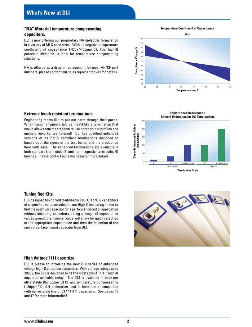
Tuning Rod KitsDLI-designed tuning rods to utilize our C06, C11 or C17 capacitors of a specified value attached to our High-Q insulating holder to find the optimum capacitor for a particular circuit or application without soldering capacitors. Using a range of capacitance values around the nominal value will allow for quick selection of the appropriate capacitance and then the selection of the correct surface mount capacitor from DLI.

3 www.dilabs.com
Simplified Frequency & Product Application Chart

www.dilabs.com 4
General InformationMaterial & Case Size Summary Sheets
Working DLI Case Size Cap Value Cap Series Voltage Series Footprint Range (pF) Typical ESR Resonance (WVDC) in. (mm) (pF) 150 MHz 500 MHz 1 GHz (MHz) max
1 0.067 0.080 0.136 9200
C11AH .055 x .055 0.1 to 100 10 0.044 0.071 0.104 3000 250
(1.40 x 1.40)
100 0.032 0.055 0.086 1000
1 0.059 0.063 0.114 9064
C17AH .110 x .110
0.1 to 1000 10 0.039 0.060 0.085 3100 1000
(2.79 x 2.79)
100 0.024 0.050 0.074 1290
10 0.059 0.094 0.138 3100
C18AH .110 x .110
0.1 to 1000 100 0.028 0.069 0.109 1290 1000
(2.79 x 2.79)
1000 0.023 0.063 – 400
10 0.074 0.207 0.249 2480
.220 x .245 100 0.048 0.116 0.190 1000 2500
C22AH
(5.84 x 6.35) 1 to 2700
1000 0.028 0.140 – 320
2700 0.027 – – 214
10MHz 30MHz 100MHz
15 0.066 0.033 0.027 2100
C40AH .380 x .380 1 to 5100 100 0.018 0.026 0.052 680 7200
(9.65 x 9.65) 1000 0.009 0.017 0.033 210
5100 0.008 0.016 0.033 95
AHTCC (ppm/°C)
(-55° to +125°C)Porcelain (P90)
+90 ±20
Working DLI Case Size Cap Value Cap Series Voltage Series Footprint Range (pF) Typical ESR Resonance (WVDC) in. (mm) (pF) 150 MHz 500 MHz 1 GHz (MHz) max
1 0.182 0.276 0.428 10300
C06CF .063 x .030 0.1 to 47 10 0.095 0.159 0.243 3200 250
(1.60 x 0.80)
47 0.081 0.127 0.173 1400
1 0.073 0.089 0.146 9900
C11CF .055 x .055
0.1 to 100 10 0.049 0.075 0.107 3100 250
(1.40 x 1.40)
100 0.040 0.073 0.111 970
1 0.073 0.082 0.124 9060
C17CF .110 x .110 0.1 to 1000 10 0.065 0.098 0.136 3100 1000
(2.79 x 2.79)
100 0.041 0.070 0.102 1300
1000 0.034 0.073 – 400
1 0.068 0.086 0.158 9060
C18CF .110 x .110 0.1 to 1000 10 0.058 0.087 0.118 3100 1000
(2.79 x 2.79)
150 0.041 0.068 – 1000
10 0.072 0.113 0.164 2480
.220 x .245 100 0.047 0.079 0.119 1000 2500
C22CF
(5.84 x 6.35) 1 to 2700
1000 0.036 0.067 – 320
2700 0.035 – – 214
10MHz 30MHz 100MHz
10 0.121 0.054 0.037 2100
C40CF .380 x .380 1 to 5100 100 0.044 0.038 0.045 680 7200
(9.65 x 9.65) 1000 0.032 0.036 0.038 210
5100 0.011 0.016 0.040 95
CFTCC (ppm/°C)
(-55° to +125°C)Porcelain (NP0)
0 ±15
ESR and Resonance data is of typical performance and can vary from lot to lot.

5 www.dilabs.com
General Information Material & Case Size Summary Sheets
DLI Case Size Cap Value Cap Series Series Footprint Range (pF) Typical ESR Resonance in. (mm) (pF) 150 MHz 500 MHz 1 GHz (MHz)
1 0.090 0.135 0.207 10300
C06MS .063 x .030 0.3 to 100 10 0.058 0.099 0.140 3200
(1.60 x 0.80)
100 0.040 0.073 0.104 1400
1 0.200 0.140 0.190 10300
C08MS .080 x .050
0.2 to 470 10 0.065 0.090 0.140 3200
(2.0 x 1.27)
100 0.030 0.045 0.065 1400
1 0.160 0.110 0.120 9900
C11MS .055 x .055 0.2 to 220
10 0.060 0.090 0.120 3100
(1.40 x 1.40) 100 0.035 0.045 0.070 220
10 0.642 0.097 0.110 3100
C17MS .110 x .110 0.3 to 2200
100 0.041 0.076 0.090 1300
(2.79 x 2.79) 1000 0.028 0.044 0.109 400
2200 0.027 0.040 0.095 200
MSTCC (ppm/°C)
(-55° to +125°C)Ceramic (NP0)
0 ±30
Working DLI Case Size Cap Value Cap Series Voltage Series Footprint Range (pF) Typical ESR Resonance (WVDC) in. (mm) (pF) 150 MHz 500 MHz 1 GHz (MHz) max
1 0.091 0.166 0.235 8796
C11NA .055 x .055 0.1 to 100 10 0.064 0.117 0.166 2994 250
(1.40 x 1.40)
100 0.046 0.083 0.117 1019
1 0.047 0.086 0.121 10360
C17NA .110 x .110 0.1 to 1000
10 0.033 0.061 0.085 3238
(2.79 x 2.79) 100 0.024 0.043 0.060 1012 1000
1000 0.017 0.030 0.043 316
NATCC (ppm/°C)
(-55° to +125°C)Ceramic (NP0)
N30 0 ±15
Working DLI Case Size Cap Value Cap Series Voltage Series Footprint Range (pF) Typical ESR Resonance (WVDC) in. (mm) (pF) 150 MHz 500 MHz 1 GHz (MHz) max
1 0.081 0.095 0.148 9820
C04UL .040 x .020 0.1 to 10 5 0.038 0.057 0.088 3930 200
(1.0 x 0.5)
10 0.036 0.058 0.087 2650
5 0.052 0.072 0.107 1750
C06UL .063 x .030
0.1 to 47 15 0.028 0.041 0.064 1010 250
(1.60 x 0.80)
47 0.023 0.043 0.070 570
5.6 0.053 0.086 0.129 5000
C07UL .110 x .070
0.1 to 100 10 0.029 0.041 0.066 3960 250
(2.79 x 1.72)
30 0.017 0.023 0.036 2540
5.1 0.051 0.078 0.126 6000
C08UL .080 x .050
0.1 to 100 9.5 0.041 0.060 0.094 4620 250
(2.0 x 1.27)
11 0.041 0.064 0.103 4340
2 0.066 0.084 0.125 7530
C11UL .055 x .055 0.1 to 100 10 0.037 0.057 0.086 3800 250
(1.40 x 1.40)
100 0.022 0.042 0.081 1430
10 0.040 0.056 0.082 2940
.110 x .110 100 0.021 0.035 0.057 910 1000
C17UL
(2.79 x 2.79) 0.1 to 1000
470 0.016 0.029 – 420
ULTCC (ppm/°C)
(-55° to +125°C)Ceramic (NP0)
0 ±30
Consult factory for additional case size data.
See page 21 for Working Voltage Rating (WVDC).
www.dilabs.com 6
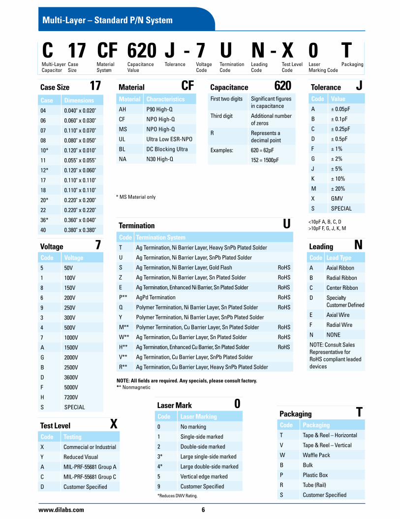
Multi-Layer – Standard P/N System
C 17 CF 620 J - 7 U N - X 0 T Multi-Layer Case Material Capacitance Tolerance Voltage Termination Leading Test Level Laser Packaging Capacitor Size System Value Code Code Code Code Marking Code
Case Dimensions04 0.040" x 0.020"
06 0.060" x 0.030"
07 0.110" x 0.070"
08 0.080" x 0.050"
10* 0.120" x 0.010"
11 0.055" x 0.055"
12* 0.120" x 0.060"
17 0.110" x 0.110"
18 0.110" x 0.110"
20* 0.220" x 0.200"
22 0.220" x 0.220"
36* 0.360" x 0.040"
40 0.380" x 0.380"
Case Size 17Material CharacteristicsAH P90 High-Q
CF NPO High-Q
MS NPO High-Q
UL Ultra Low ESR-NPO
BL DC Blocking Ultra
NA N30 High-Q
Material CFFirst two digits Significant figures
in capacitance
Third digit Additional number of zeros
R Represents a decimal point
Examples: 620 = 62pF
152 = 1500pF
Capacitance 620Code ValueA ± 0.05pF
B ± 0.1pF
C ± 0.25pF
D ± 0.5pF
F ± 1%
G ± 2%
J ± 5%
K ± 10%
M ± 20%
X GMV
S SPECIAL
Tolerance J
Code Voltage5 50V
1 100V
8 150V
6 200V
9 250V
3 300V
4 500V
7 1000V
A 1500V
G 2000V
B 2500V
D 3600V
F 5000V
H 7200V
S SPECIAL
Voltage 7Code Lead TypeA Axial Ribbon
B Radial Ribbon
C Center Ribbon
D Specialty Customer Defined
E Axial Wire
F Radial Wire
N NONE
NOTE: Consult Sales Representative for RoHS compliant leaded devices
Leading NCode Termination SystemT Ag Termination, Ni Barrier Layer, Heavy SnPb Plated Solder
U Ag Termination, Ni Barrier Layer, SnPb Plated Solder
S Ag Termination, Ni Barrier Layer, Gold Flash RoHS
Z Ag Termination, Ni Barrier Layer, Sn Plated Solder RoHS
E Ag Termination, Enhanced Ni Barrier, Sn Plated Solder RoHS
P** AgPd Termination RoHS
Q Polymer Termination, Ni Barrier Layer, Sn Plated Solder RoHS
Y Polymer Termination, Ni Barrier Layer, SnPb Plated Solder
M** Polymer Termination, Cu Barrier Layer, Sn Plated Solder RoHS
W** Ag Termination, Cu Barrier Layer, Sn Plated Solder RoHS
H** Ag Termination, Enhanced Cu Barrier, Sn Plated Solder RoHS
V** Ag Termination, Cu Barrier Layer, SnPb Plated Solder
R** Ag Termination, Cu Barrier Layer, Heavy SnPb Plated Solder
Termination U
Code TestingX Commecial or Industrial
Y Reduced Visual
A MIL-PRF-55681 Group A
C MIL-PRF-55681 Group C
D Customer Specified
Test Level XCode Laser Marking0 No marking
1 Single-side marked
2 Double-side marked
3* Large single-side marked
4* Large double-side marked
5 Vertical edge marked
9 Customer Specified*Reduces DWV Rating.
Laser Mark 0Code PackagingT Tape & Reel – Horizontal
V Tape & Reel – Vertical
W Waffle Pack
B Bulk
P Plastic Box
R Tube (Rail)
S Customer Specified
Packaging T
NOTE: All fields are required. Any specials, please consult factory.** Nonmagnetic
* MS Material only
<10pF A, B, C, D>10pF F, G, J, K, M

7 www.dilabs.com
General Information
Dielectric CodeTemperature Coefficient
-55°C to +125°C(ppm/°C Maximum)
DissipationFactor @ 1 MHz(% Maximum)
Insulation Resistance (MΩ)
@ +25°C @ +125°C
AH P90 ± 20 0.05 >106 >105
CF 0 ± 15 0.05 >106 >105
UL 0 ± 30 0.05 >105 >104
MS 0 ± 30 0.05 >105 >104
*BL ± 15% 2.50 >104 >103
NA N30 ± 15 0.05 >106 >105
All test conditions are per MIL-PRF-55681 revision A. Dissipation Factor applies to values of 4.7pF or greater. *Broadband Blocks only.
Other Dielectric formulations may be available, please contact your Sales Representative.
DLI Multi-Layer Dielectric Materials
Code Termination System Application
TAg TerminationNi Barrier Layer
Heavy SnPb Plated Solder
• High Reliability Applications• Hand Soldering
UAg Termination Ni Barrier Layer
SnPb Plated Solder
• High Reliability Applications• High Volume & Hand Solder
Assembly
SRoHS
Ag TerminationNi Barrier Layer
Gold Flash
• Specialty Solder, Epoxy Applications
• Standard for 0402
ZRoHS
Ag TerminationNi Barrier LayerSn Plated Solder
• High Volume & Hand Solder Assembly
ERoHS
Ag Termination Enhanced Ni Barrier
Sn Plated Solder
• High Volume & Hand Solder Assembly
• Ultra Leach Resistant
PRoHS
AgPd Termination • Non-Magnetic Applications
QRoHS
Polymer TerminationNi Barrier LayerSn Plated Solder
• Resistant to Cracking• High Volume & Hand Solder
Assembly
Termination SystemsCode Termination System Application
YPolymer Termination
Ni Barrier LayerSn Plated Solder
• Resistant to Cracking• High Reliability Applications• High Volume & Hand Solder
Assembly
MRoHS
Polymer TerminationCu Barrier LayerSn Plated Solder
• Resistant to Cracking• Non-Magnetic Application• High Volume & Hand Solder
Assembly
WRoHS
Ag TerminationCu Barrier Layer Sn Plated Solder
• Non-Magnetic Application• High Volume
HRoHS
Ag TerminationEnhanced Cu Barrier
Sn Plated Solder
• Non-Magnetic Applications• High Vol. & Hand Solder Assembly• Ultra Leach Resistant
VAg Termination
Cu Barrier LayerSnPb Plated Solder
• Non-Magnetic Applications• High Reliability Applications• High Volume & Hand Solder
Assembly
R Ag Termination
Cu Barrier LayerHeavy SnPb Plated Solder
• Non-Magnetic Applications• High Reliability Applications• Hand Soldering
UL, MS AHCF
Capa
cita
nce
Chan
ge %
1.25
1
0.75
0.5
0.25
0
-0.25
-0.5
-0.75
-1 -55 -40 -20 0 20 40 60 80 100 120
Temperature deg C
Temperature Coefficient of Capacitance
www.dilabs.com 8
Test Level Codes
Test code Inspection Description (see individual part pages for additional detail)
Y 100% IR, 1% AQL visual, 1% AQL Electrical (DWV, Cap., DF)
X 100% IR, 100 % visual, 1% AQL Electrical (DWV, Cap., DF)
A Group A testing per MIL – PRF – 55681
C Group C testing per MIL – PRF – 55681
D Customer Defined
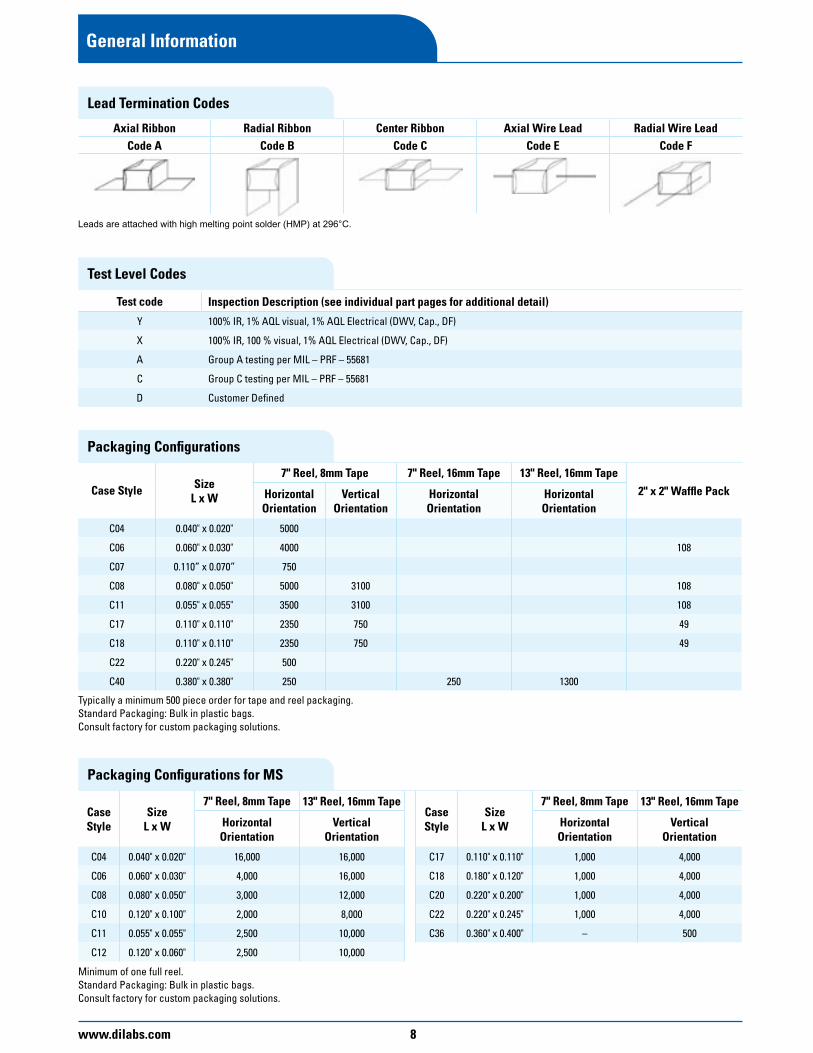
Axial Ribbon Radial Ribbon Center Ribbon Axial Wire Lead Radial Wire LeadCode A Code B Code C Code E Code F
Leads are attached with high melting point solder (HMP) at 296°C.
Lead Termination Codes
Packaging Configurations
Case Style SizeL x W
7" Reel, 8mm Tape 7" Reel, 16mm Tape 13" Reel, 16mm Tape2" x 2" Waffle PackHorizontal
OrientationVertical
OrientationHorizontalOrientation
HorizontalOrientation
C04 0.040" x 0.020" 5000
C06 0.060" x 0.030" 4000 108
C07 0.110” x 0.070” 750
C08 0.080" x 0.050" 5000 3100 108
C11 0.055" x 0.055" 3500 3100 108
C17 0.110" x 0.110" 2350 750 49
C18 0.110" x 0.110" 2350 750 49
C22 0.220" x 0.245" 500
C40 0.380" x 0.380" 250 250 1300
Typically a minimum 500 piece order for tape and reel packaging.Standard Packaging: Bulk in plastic bags.Consult factory for custom packaging solutions.
Packaging Configurations for MS
Case Style
SizeL x W
7" Reel, 8mm Tape 13" Reel, 16mm Tape
HorizontalOrientation
VerticalOrientation
C04 0.040" x 0.020" 16,000 16,000
C06 0.060" x 0.030" 4,000 16,000
C08 0.080" x 0.050" 3,000 12,000
C10 0.120" x 0.100" 2,000 8,000
C11 0.055" x 0.055" 2,500 10,000
C12 0.120" x 0.060" 2,500 10,000
Minimum of one full reel.Standard Packaging: Bulk in plastic bags.Consult factory for custom packaging solutions.
Case Style
SizeL x W
7" Reel, 8mm Tape 13" Reel, 16mm Tape
HorizontalOrientation
VerticalOrientation
C17 0.110" x 0.110" 1,000 4,000
C18 0.180" x 0.120" 1,000 4,000
C20 0.220" x 0.200" 1,000 4,000
C22 0.220" x 0.245" 1,000 4,000
C36 0.360" x 0.400" – 500
General Information

9 www.dilabs.com
General Information
Recommended Pad Spacing Dimensions (inches)
Case SizeInternal
ElectrodeReflow Soldering Wave Soldering
A B C A B C
C04Horizontal 0.076 0.036 0.010 0.106 0.036 0.020
Vertical Not Recommended Not Recommended
C06Horizontal 0.106 0.051 0.020 0.136 0.051 0.020
Vertical Not Recommended Not Recommended
C07Horizontal 0.119 0.141 0.020 0.149 0.141 0.020
Vertical Not Recommended Not Recommended
C08Horizontal 0.127 0.071 0.020 0.157 0.071 0.020
Vertical 0.127 0.064 0.020 0.157 0.064 0.020
C11Horizontal 0.114 0.084 0.020 0.144 0.084 0.020
Vertical 0.114 0.063 0.020 0.144 0.063 0.020
C17Horizontal 0.182 0.147 0.040 0.212 0.147 0.040
Vertical 0.182 0.115 0.040 0.212 0.115 0.040
C18Horizontal 0.182 0.152 0.070 0.212 0.152 0.070
Vertical 0.182 0.115 0.070 0.212 0.115 0.070
C22Horizontal 0.282 0.288 0.110 0.312 0.288 0.110
Vertical Not Recommended Not Recommended
C40Horizontal 0.445 0.420 0.290 0.475 0.420 0.290
Vertical Not Recommended Not Recommended
Case Size Definitions
Case Size Case Size EIA
Available Termination Style
Width(1) Length(1)
Thickness(1)
(Max)
Gap Min
(Between Bands)
Band Min(2)
(Plated)Band Max(2)
(Plated)Inches mm Inches mm
Min Max Min Max Min Max Min Max Inches mm Inches mm Inches mm Inches mm
04BL 0402 U S 0.014 0.026 0.362 0.667 0.034 0.046 0.869 1.173 0.025 0.640 0.008 0.193 0.004 0.097 0.017 0.427
04UL 0402 S 0.014 0.026 0.362 0.667 0.034 0.046 0.869 1.173 0.025 0.640 0.008 0.193 0.004 0.097 0.017 0.427
06BL 0603 U S Z 0.023 0.038 0.579 0.960 0.051 0.069 1.303 1.760 0.032 0.800 0.010 0.241 0.007 0.169 0.027 0.680
06CF 0603 U S Z E P W H V R 0.023 0.038 0.579 0.960 0.051 0.069 1.303 1.760 0.032 0.800 0.010 0.241 0.007 0.169 0.027 0.680
06UL 0603 U S Z 0.022 0.041 0.555 1.040 0.051 0.076 1.303 1.920 0.033 0.827 0.014 0.362 0.007 0.169 0.027 0.680
07UL 0711 S Z 0.090 0.131 2.292 3.334 0.052 0.089 1.327 2.267 0.105 2.667 0.019 0.483 0.008 0.193 0.047 1.200
08BL 0805 U S Z 0.040 0.061 1.013 1.547 0.065 0.097 1.641 2.454 0.054 1.360 0.010 0.241 0.014 0.362 0.041 1.040
08UL 0805 U S Z 0.040 0.061 1.013 1.547 0.065 0.097 1.641 2.454 0.054 1.360 0.010 0.241 0.014 0.362 0.041 1.040
11 0505 U S Z E P Q Y M W H V R 0.038 0.074 0.965 1.867 0.043 0.074 1.086 1.867 0.053 1.334 0.014 0.362 0.008 0.193 0.029 0.733
11 0505 T 0.038 0.074 0.965 1.867 0.043 0.084 1.086 2.134 0.053 1.334 0.014 0.362 N/A N/A N/A N/A
17 1111 U S Z E P Q Y M W H V R 0.090 0.131 2.292 3.334 0.095 0.137 2.413 3.467 0.105 2.667 0.038 0.965 0.008 0.193 0.047 1.200
17 1111 T 0.090 0.137 2.292 3.467 0.095 0.152 2.413 3.867 0.105 2.667 0.038 0.965 N/A N/A N/A N/A
18 1111(3) U Z E W H V 0.090 0.142 2.292 3.600 0.095 0.152 2.413 3.867 0.105 2.667 0.043 1.086 0.008 0.193 0.047 1.200
22 2222 U S Z E P Q Y M W H V R 0.223 0.278 5.671 7.068 0.200 0.252 5.067 6.401 0.137 3.467 0.124 3.137 N/A N/A N/A N/A
40 3838 U S Z E P Q Y M W H V R 0.352 0.410 8.928 10.401 0.352 0.415 8.928 10.535 0.137 3.467 0.276 6.998 N/A N/A N/A N/A
(1) Dimensions listed include the termination. (2) Band widths are from corner to corner of part.(3) Enhanced voltage handling case size.

www.dilabs.com 10
Application Notes
Chip SelectionMultilayer capacitors (MLC) are categorized by dielectric performance with temperature, or “temperature coefficient”, as these devices vary in behavior over temperature. The choice of component is thus largely determined by the temperature stability required of the device, i.e. type of dielectric, and the size necessary for a given capacitance and voltage rating. The following items are pertinent to chip selection:
Dielectric TypeCF: Ultra stable Class I dielectric exceeds EIA COG requirements with negligible dependence of electrical properties on temperature, voltage, frequency and time, used in circuitry requiring very stable performance.
AH: EIA Class 1 dielectric with a dielectric constant that increases with temperature (90ppm/°C). Useful for temperature compensation where other board components may be losing capacitance with temperature.
NA: EIA Class 1 dielectric with a negative TCC. Useful in situations where other board components are gaining capacitance with temperature.
UL: EIA Stable Class 1 dielectric, with extremely low ESR. Useful in any application where heat generation or signal loss are concerns.
BL: EIA Stable Class II dielectric (X7R), with predictable change in properties with temperature, voltage, frequency and time. Used as blocking, de-coupling, bypassing and frequency discriminating elements. This dielectric is ferroelectric, and provides higher capacitance than Class 1.
MS: Stable Class 1 dielectric. Particularly suited to high capacitance or high volume applications.
Capacitor SizeSize selection is based primarily on capacitance value, voltage rating, and resonance frequency. Smaller units are generally less expensive; 0603 is the most economical size. Because mass affects the thermal shock behavior of chips, size selection must consider the soldering method used to attach the chip to the board. C18 and smaller can be wave, vapor phase or reflow soldered. Larger units require reflow soldering.
Termination MaterialNickel barrier termination, with exceptional solder leach resistance is recommended for all applications involving solder. DLI offers two versions of the nickel barrier termination. The “Z” termination is a nickel barrier with 100% matte tin for a lead free capacitor. The “U” termination is a nickel barrier with 90/10 tin/lead for military applications. Non-magnetic versions of these termination finishes are also available.
Solder LeachingDLI’s termination finishes are designed to withstand RoHS attachment methods. During soldering, time above 230°C should be minimized to reduce thinning of the barrier layer and subsequent bond failure. DLI offers enhanced magnetic and non-magnetic termination finishes for applications requiring extended soldering time or repeated reflow cycles. Please consult your Sales Representative when ordering.
PackagingUnits are available in bulk, reeled or in waffle pack.
Attachment MethodsBonding of capacitors to substrates can be categorized into two methods, those involving solder, which are prevalent, and those using other materials, such as epoxies and thermo-compression or ultrasonic bonding with wire. Please see DLI application note “Recommended Solder Attachment Techniques for Multi-Layer Chip and Pre-Thinned Capacitors” located on out website, www.dilabs.com.
SolderingSoldering methods commonly used in the industry and recommended are Reflow Soldering, Wave Soldering, and to a lesser extent, Vapor Phase Soldering. All these methods involve thermal cycling of the components and therefore the rate of heating and cooling must be controlled to preclude thermal shocking of the devices. In general, rates which do not exceed 120°C per minute and a temperature spike of 100°C maximum for any soldering process on sizes C18 and smaller is advisable. Other precautions include post soldering handling, primarily avoidance of rapid cooling with contact with heat sinks, such as conveyors or cleaning solutions.
Large chips are more prone to thermal shock as their greater bulk will result in sharper thermal gradients within the device during thermal cycling. Units larger than C18 experience excessive stress if processed through the fast cycles typical of solder wave or vapor phase operations. Solder reflow is most applicable to the larger chips as the rates of heating and cooling can be slowed within safe limits. In general, rates that do not exceed 60°C per minute and a temperature spike of 50°C maximum for any soldering process on sizes larger than C18 is advisable.
Attachment using a soldering iron requires extra care, particularly with large components, as thermal gradients are not easily controlled and may cause cracking of the chip. Precautions include preheating of the assembly to within 100°C of the solder flow temperature, the use of a fine tip iron which does not exceed 30 watts, and limitation of contact of the iron to the circuit pad areas only.
BondingHybrid assembly using conductive epoxy or wire bonding requires the use of silver palladium or gold terminations. Nickel barrier termination is not practical in these applications, as intermetallics will form between the dissimilar metals. The ESR will increase over time and may eventually break contact when exposed to temperature cycling.
CleaningChip capacitors can withstand common agents such as water, alcohol and degreaser solvents used for cleaning boards. Ascertain that no flux residues are left on the chip surfaces as these diminish electrical performance.
DLI Shelf LifeCapacitors are solderable for a maximum of one year from the date of shipment if properly stored in the original packaging. Dry nitrogen storage is preferable for longer periods.

11 www.dilabs.com
Application Notes
Board Design ConsiderationsThe amount of solder applied to the chip capacitor will influence the reliability of the device. Excessive solder can create thermal and tensile stresses on the component which could lead to fracturing of the chip or the solder joint itself. Insufficient or uneven solder application can result in weak bonds, rotation of the device off line or lifting of one terminal off the pad (tombstoning). The volume of solder is process and board pad size dependent. WAVE SOLDERING exposes the devices to a large solder volume, hence the pad size area must be restricted to accept an amount of solder which is not detrimental to the chip size utilized. Typically the pad width is 66% of the component width, and the length is .030" (.760 mm) longer than the termination band on the chip. An 0805 chip which is .050" wide and has a .020" termination band therefore requires a pad .033" wide by .050" in length. Opposing pads should be identical in size to preclude uneven solder fillets and mismatched surface tension forces which can misalign the device. It is preferred that the pad layout results in alignment of the long axis of the chips at right angles to the solder wave, to promote even wetting of all terminals. Orientation of components in line with the board travel direction may require dual waves with solder turbulence to preclude cold solder joints on the trailing terminals of the devices, as these are blocked from full exposure to the solder by the body of the capacitor. Restrictions in chip alignment do not apply to SOLDER REFLOW or VAPOR PHASE processes, where the solder volume is controlled by the solder paste deposition on the circuit pads There are practical limitations on capacitor sizes that prohibit reliable direct mounting of chip capacitors larger than 2225 to a substrate. Without mechanical restriction, thermally induced stresses are released once the capacitor attains a steady state condition, at any given temperature. Capacitors bonded to substrates, however, will retain some stress, due primarily to the mismatch of expansion of the component to the substrate; the residual stress on the chip is also influenced by the ductility and hence the ability of the bonding medium to relieve the stress. Unfortunately, the thermal expansions of chip capacitors differ significantly from those of substrate materials.
Recommended Printed Wire Board Land Patterns
Printed Wire Board land pattern design for chip components is critical to ensure a reliable solder fillet, and to reduce nuisance type manufacturing problems such as component swimming and tombstoning. The land pattern suggested can be used for reflow and wave solder operations as noted. Land patterns constructed with these dimensions will yield optimized solder fillet formation and thus reduce the possibility of early failure.1
A = (Max Length) + 0.030” (.762mm)* B = (Max Width) + 0.010” (.254mm)** C = (Min Length) – 2 (Nominal Band)***
Temperature Precautions
The rate of heating and cooling must be controlled to preclude thermal cracking of ceramic capacitors. Soldering temperatures should not exceed 200°C per minute, temperature variation must not exceed 100°C maximum for any solder operation. Avoid forced cooling or contact with heat sinks, such as conveyor belts, metal tables or cleaning solutions, before the chips reach ambient temperatures.
MLC Orientation - Horizontal and Vertical MountingThe orientation of the MLC relative to the ground plane affects the devices’ impedance. When the internal electrodes are parallel to the ground plane (Horizontal mounting) the impedance of the MLC resembles a folded transmission line driven from one end. The below graph shows the modeled insertion loss and parallel resonances of C17AH101K-7UN-X0T with horizontal mounting. When the internal electrodes are perpendicular to the ground plane (Vertical mounting, bottom graph) the MLC impedance resembles a folded transmission line driven from the center reducing resonance effects. C11,17 are available with vertical or horizontal orientation in tape and reel packaging. Modeling can be done in CapCad. HP/EEs of series 4 contains models for C11 and C17 in the element libraries under Dielectric Laboratories MLC.
* Add 0.030” for Wave Solder operations.** Replace “Max Width” with “Max Thickness” for vertical mounting.*** ”C” to be no less than 0.02”, change “A” to (Max Length) + 0.020”. For CO4 ”C” to be no less than 0.01”.
1. Frances Classon, James Root, Martin Marietta Orlando Aerospace, “Electronics Packaging and Interconnection Handbook”.

www.dilabs.com 12
AH Series: P90 Porcelain Capacitors
Dielectric Characteristics
Dielectric Material
Code
Temperature Coefficient
(ppm/°C Maximum)
Dissipation Factor
(% @ 1MHz Maximum)
Dielectric Withstanding Voltage Insulation Resistance(MΩ Minimum)
Aging PiezoelectricEffects
Dielectric Absorption
Voltage Rating (Volts)
DWV(Volts) @ +25°C @ +125°C
AH +90 ± 20 0.05Please see
chart (pg. 13)
250% of WVDC for 5 sec unless
specified in chart (pg. 13)
106 105 None None None
Part Number Breakdown*
*C 17 AH 620 J - 7 U N - X 0 TMulti Layer
Case Size Material System
Capacitance Code
Tolerance Level
Voltage Code
Termination Code
Leading Code
Test Level Marking Code
Packaging
Benefits
Oscillators Timing Circuits FiltersRF Power Amplifiers & Delay LinesStable TC, -55° to +125°C Operating Range High QSMD CompatibilityLower ESRPower Handling, High Voltage
Available Termination TypesC11 T, U, S, Z, E, P, Q, Y, M, W, H, V, R
C17 T, U, S, Z, E, P, Q, Y, M, W, H, V, R
C18 U, Z, E, Y, W, H
C22 U, S, Z, E, P, Q, Y, M, W, H, V, R
C40 T, U, S, Z, E, P, Q, Y, M, W, H, V, R
Available Laser MarkingC11 0, 1, 2, 5C17 0, 1, 2, 3, 4, 5C18 0, 1, 2, 5C22 0, 1C40 0, 1
Available PackagingC11 T, V, W, B, P, SC17 T, V, W, B, P, SC18 T, V, W, B, P, SC22 T, B, P, SC40 T, B, P, S, R
Code Termination SystemT Ag Term, Ni Barrier Layer, Heavy
SnPb Plated Solder
U Ag Termination, Ni Barrier Layer, SnPb Plated Solder
S Ag Termination, Ni Barrier Layer, Gold Flash, RoHS
Z Ag Termination, Ni Barrier Layer, Sn Plated Solder, RoHS
E Ag Termination, Enhanced Ni Barrier, Sn Plated Solder, RoHS
P AgPd Termination, RoHS
Q Polymer Termination, Ni Barrier Layer, Sn Plated Solder, RoHS
Y Polymer Termination, Ni Barrier Layer, SnPb Plated Solder,
M Polymer Termination, Cu Barrier Layer, Sn Plated Solder, RoHS
W Ag Termination, Cu Barrier Layer, Sn Plated Solder
H Ag Termination, Enhanced Cu Barrier, Sn Plated Solder, RoHS
V Ag Termination, Cu Barrier Layer, SnPb Plated Solder
R Ag Termination, Cu Barrier Layer, Heavy SnPb Plated Solder
Code Lead TypesA Axial Ribbon
B Radial RibbonC Center RibbonD Customer
SpecifiedE Axial WireF Radial WireN None
Code Laser Marking0 No marking1 Single-side
marked2 Double-side
marked3 Large single-
side marked4 Large double-
side marked5 Vertical edge
marked9 Customer
Specified
Available Lead TypesC11 A, B, DC17 A, B, C, D, E, FC18 A, B, C, D, E, FC22 A, B, C, D, E, FC40 A, B, C, D, E, F
Special Leading requirements available.
Test Level – All Case SizesX StandardY Reduced VisualA MIL-PRF-55681
Group AC MIL-PRF-55681
Group CD Customer
Specified Code PackagingT Tape & Reel –
HorizontalV Tape & Reel –
VerticalW Waffle PackB BulkP Plastic BoxR Tube (Rail)S Customer
Specified
*See page 6 for complete part number system.
Description
Porcelain Capacitors Positive TC “P90” Low ESR, High Q Capacitance Range 0.1 - 5100 pF High Self-resonance Low Noise Established Reliability
Functional Applications
Impedance Matching DC BlockingBypass Coupling Tuning & Feedback Amplifier Matching NetworksVCO Frequency Stabilization Filtering, Diplexers & Antenna MatchingHigh RF Power Circuits

13 www.dilabs.com
AH Series: P90 Porcelain Capacitors
Capacitance and Voltage TableCAP CODE CAP (pF) CASE SIZE C11 0505 CASE SIZE C17 1111 CASE SIZE C18 1111 CASE SIZE C22 2225 CASE SIZE C40 3838
0R1 0.1
250VCode 9
DWV = 625V
0R2 0.20R3 0.3
1000VCode 7
DWV = 2500V
2000VCode G
DWV = 2500V
2500VCode B
DWV = 3000V
7200VCode H
DWV = 8700V
0R4 0.40R5 0.50R6 0.60R7 0.70R8 0.80R9 0.91R0 1.01R1 1.11R3 1.31R4 1.41R5 1.51R6 1.61R7 1.71R8 1.81R9 1.92R0 2.02R1 2.12R2 2.22R4 2.42R7 2.73R0 3.03R3 3.33R6 3.63R9 3.94R3 4.34R7 4.75R1 5.15R6 5.66R2 6.26R8 6.87R5 7.58R2 8.29R1 9.1100 10110 11120 12130 13150 15160 16180 18200 20220 22240 24270 27300 30330 33360 36
200VCode 6
DWV = 500V
390 39430 43470 47510 51560 56620 62680 68750 75820 82910 91101 100111 110
500VCode 4
DWV = 1250V
1000VCode 7
DWV = 2500V
3600VCode D
DWV = 4400V
121 120131 130151 150161 160181 180201 200221 220
200VCode 6
DWV = 500V
200VCode 6
DWV = 500V
241 240271 270301 300
1500VCode A
DWV = 1800V
331 330361 360391 390431 430
2500VCode B
DWV = 3750V
471 470511 510 100V
Code 1DWV = 250V
100VCode 1
DWV = 250V1000VCode 7
DWV = 1500V
561 560621 620681 680
50VCode 5
DWV = 125V
50VCode 5
DWV = 125V
751 750
1000VCode 7
DWV = 1500V
821 820911 910102 1000122 1200152 1500 500V
Code 4, DWV = 1250V182 1800222 2200 300V
Code 3272 2700500V
Code 4DWV = 1250V
332 3300392 3900472 4700512 5100
Reel QTY Horizontal 3500 2350 2350 500 250
Special capacitance values available upon request.
www.dilabs.com 14
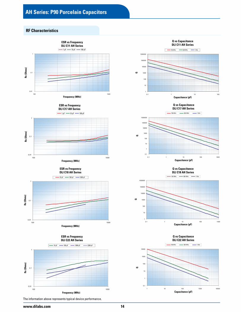
AH Series: P90 Porcelain Capacitors
RF Characteristics
The information above represents typical device performance.
15 www.dilabs.com
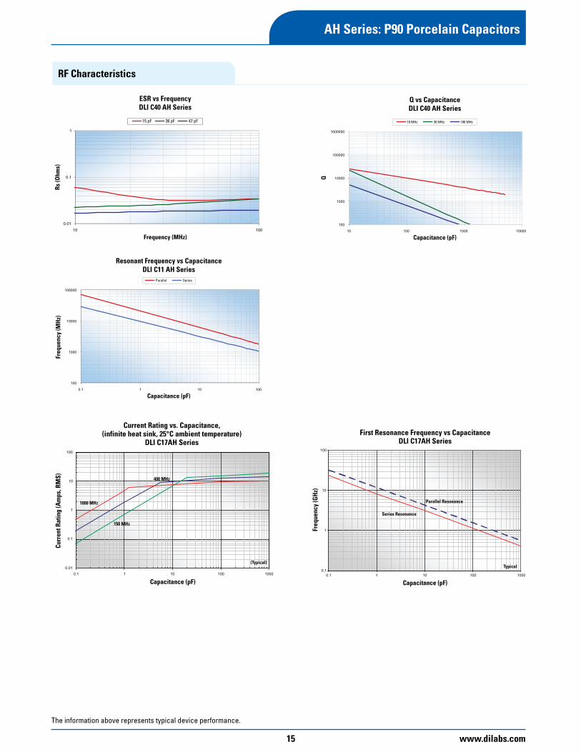
AH Series: P90 Porcelain Capacitors
RF Characteristics
The information above represents typical device performance.

www.dilabs.com 16
CF Series: Ultrastable Porcelain Capacitors
Dielectric Characteristics
Dielectric Material
Code
Temperature Coefficient
(ppm/°C Maximum)
Dissipation Factor
(% @ 1MHz Maximum)
Dielectric Withstanding Voltage Insulation Resistance(MΩ Minimum)
Aging PiezoelectricEffects
Dielectric Absorption
Voltage Rating (Volts)
DWV(Volts) @ +25°C @ +125°C
CF 0 ± 15 0.05Please see
chart (pg. 17)
250% of WVDC for 5 sec unless
specified in chart(pg. 17)
106 105 None None None
Part Number Breakdown*
*C 17 CF 620 J - 7 U N - X 0 TMulti Layer
Case Size Material System
Capacitance Code
Tolerance Level
Voltage Code
Termination Code
Leading Code
Test Level Marking Code
Packaging
Available Termination TypesC06 U, S, Z, E, P, Q, Y, W, H, V, R
C11 T, U, S, Z, E, P, Q, Y, W, H, V, R
C17 T, U, S, Z, E, P, Q, Y, W, H, V, R
C18 U, Q, Y, V, W, H, Z
C22 U, S, Z, E, P, Q, Y, W, H, V, R
C40 T, U, S, P, Q, Y, W, H, V, R,
Available Laser MarkingC06 0, 1 C11 0, 1, 2, 5C17 0, 1, 2, 3, 4, 5C18 0, 1, 2, 5C22 0, 1C40 0, 1
Available PackagingC06 T, W, B, SC11 T, V, W, B, P, SC17 T, V, W, B, P, SC18 T, V, W, B, P, SC22 T, B, P, SC40 T, B, P, S, R
Code Lead TypesA Axial Ribbon
B Radial RibbonC Center RibbonD Customer
SpecifiedE Axial WireF Radial WireN None
Code Laser Marking0 No marking1 Single-side
marked2 Double-side
marked3 Large single-
side marked4 Large double-
side marked5 Vertical edge
marked9 Customer
Specified
Available Lead TypesC06 N/AC11 A, B, DC17 A, B, C, D, E, FC18 A, B, C, D, E, FC22 A, B, C, D, E, FC40 A, B, C, D, E, F
Special Leading requirements available.
Test Level – All Case SizesX StandardY Reduced VisualA MIL-PRF-55681
Group AC MIL-PRF-55681
Group CD Customer
Specified Code PackagingT Tape & Reel –
HorizontalV Tape & Reel –
VerticalW Waffle PackB BulkP Plastic BoxR Tube (Rail)S Customer
Specified
*See page 6 for complete part number system.
Description
Porcelain Capacitors Ultra Temperature Stable Low ESR, High Q Capacitance Range 0.1 - 5100 pF High Self-resonance Low Noise Established Reliability
Functional Applications
Impedance Matching DC Blocking Bypass Coupling Tuning & Feedback Amplifier Matching Networks VCO Frequency Stabilization Filtering, Diplexers & Antenna MatchingHigh RF Power Circuits
Benefits
Oscillators Timing Circuits FiltersRF Power Amplifiers & Delay LinesStable TC, -55° to +125°C Operating Range High Q SMD CompatibilityLower ESRPower Handling, High Voltage
Code Termination SystemT Ag Term, Ni Barrier Layer, Heavy
SnPb Plated Solder
U Ag Termination, Ni Barrier Layer, SnPb Plated Solder
S Ag Termination, Ni Barrier Layer, Gold Flash, RoHS
Z Ag Termination, Ni Barrier Layer, Sn Plated Solder, RoHS
E Ag Termination, Enhanced Ni Barrier, Sn Plated Solder, RoHS
P AgPd Termination, RoHS
Q Polymer Termination, Ni Barrier Layer, Sn Plated Solder, RoHS
Y Polymer Termination, Ni Barrier Layer, SnPb Plated Solder,
M Polymer Termination, Cu Barrier Layer, Sn Plated Solder, RoHS
W Ag Termination, Cu Barrier Layer, Sn Plated Solder
H Ag Termination, Enhanced Cu Barrier, Sn Plated Solder, RoHS
V Ag Termination, Cu Barrier Layer, SnPb Plated Solder
R Ag Termination, Cu Barrier Layer, Heavy SnPb Plated Solder

17 www.dilabs.com
CAP CODE CAP (pF) CASE SIZE C06 0603 CASE SIZE C11 0505 CASE SIZE C17 1111 CASE SIZE C18 1111 CASE SIZE C22 2225 CASE SIZE C40 38380R1 0.1
250VCode 9
250VCode 9
0R2 0.20R3 0.3
1000VCode 7
2000VCode G1000VCode 7
2500VCode B
DWV = 3000V
7200VCode H
DWV = 8700V
0R4 0.40R5 0.50R6 0.60R7 0.70R8 0.80R9 0.91R0 1.01R1 1.11R2 1.21R3 1.31R4 1.41R5 1.51R6 1.61R7 1.71R8 1.81R9 1.92R0 2.02R1 2.12R2 2.22R4 2.42R7 2.73R0 3.03R3 3.33R6 3.63R9 3.94R3 4.34R7 4.75R1 5.15R6 5.66R2 6.26R8 6.87R5 7.58R2 8.29R1 9.1100 10110 11120 12130 13150 15160 16180 18200 20220 22240 24270 27300 30330 33360 36
200VCode 6
390 39430 43470 47510 51560 56620 62680 68750 75820 82910 91101 100111 110
500VCode 4
1000VCode 7
3600VCode D
DWV = 4400V
121 120131 130151 150161 160181 180201 200221 220
200VCode 6
200VCode 6
241 240271 270301 300
1500VCode A
DWV = 1800V
331 330361 360391 390431 430
2500VCode B
DWV = 3750V
471 470511 510 100V
Code 1100V
Code 1
1000VCode 7
561 560621 620681 680
50VCode 5
50VCode 5
751 750
1000VCode 7
821 720911 910102 1000122 1200152 1500 500V
Code 4182 1800222 2200 300V
Code 3272 2700
500VCode 4
332 3300392 3900472 4700512 5100
Reel QTY 4000 3500 2350 2350 500 250
CF Series: Ultrastable Porcelain Capacitors
Capacitance and Voltage Table
Special capacitance values available upon request.

www.dilabs.com 18
CF Series: Ultrastable Porcelain Capacitors
RF Characteristics
The information above represents typical device performance.

19 www.dilabs.com
CF Series: Ultrastable Porcelain Capacitors
RF Characteristics
The information above represents typical device performance.

www.dilabs.com 20
MS Series: Low ESR, High Volume Ceramic Capacitors
Dielectric Characteristics
Dielectric Material
Code
Temperature Coefficient
(ppm/°C Maximum)
Dissipation Factor
(% @ 1MHz Maximum)
Dielectric Withstanding Voltage Insulation Resistance(MΩ Minimum)
Aging PiezoelectricEffects
Dielectric AbsorptionVoltage Rating
(Volts)DWV
(Volts) @ +25°C @ +125°C
MS 0 ± 30 0.05Please see
chart (pg. 21)
250% of WVDC for 5 sec unless
specified in chart(pg. 21)
106 104 None None None
Part Number Breakdown*
C 06 MS 101 J - 5 Z N - X 0 TMulti Layer
Case Size Material System
Capacitance Code
Tolerance Level
Voltage Code
Termination Code
Leading Code
Test Level Marking Code
Packaging
Available Termination TypesC04 ZC06 ZC08 ZC10 ZC11 ZC12 ZC17 ZC20 ZC22 ZC36 Z
Available PackagingC06 T, BC08 T, BC10 T, BC11 T, BC12 T, BC17 T, B
Code Termination SystemZ Ag Termination, Ni Barrier
Layer, Sn Plated Solder, RoHS
Code Lead TypesN None Code Laser Marking
0 No marking
Test Level – All Case SizesX StandardY Reduced VisualD Customer
Specified
Code PackagingT Tape & Reel –
HorizontalB Bulk
Description
Ceramic Capacitors NPOLow ESR, High Q Capacitance Range 0.2 - 2200 pF High Working Voltage Low Noise
Functional Applications
DC Blocking Amplifier Matching Networks VCO Frequency Stabilization Filtering, Diplexers & Antenna Matching High RF Power CircuitsBypass Coupling Tuning & Feedback Broadcast Power Amps
Benefits
High Q Stable TC, -55° to +125°C Operating Range EIA 0603 & 0805 Case Size SMD Compatibility Oscillators Timing Circuits Filters RF Power Amplifiers & Delay Lines Ultra Low ESRCeramic DielectricHigh Volume Applications
*See page 6 for complete part number system.

21 www.dilabs.com
MS Series: Low ESR, High Volume Ceramic Capacitors
Capacitance and Voltage TableCAP CODE CAP (pF) CASE SIZE C06 0603 CASE SIZE C11 0505 CASE SIZE C17 1111 CASE SIZE C22 2225 CASE SIZE 36 3640
0R1 0.10R2 0.2
50VCode 5
250VCode 9
2000VCode G
0R3 0.30R4 0.4
Code 7 1000V
2500VCode B
0R5 0.50R6 0.60R7 0.70R8 0.80R9 0.91R0 1.01R1 1.11R2 1.21R3 1.31R4 1.41R5 1.51R6 1.61R7 1.71R8 1.81R9 1.92R0 2.02R1 2.12R2 2.22R3 2.32R4 2.42R5 2.52R6 2.62R7 2.72R8 2.82R9 2.93R0 3.03R3 3.33R6 3.66R9 6.94R3 4.34R7 4.75R1 5.15R6 5.66R2 6.26R8 6.87R5 7.58R2 8.29R1 9.1100 10110 11120 12130 13150 15160 16180 18200 20220 22240 24270 27300 30330 33360 36390 39430 43470 47510 51560 56620 62680 68750 75820 82910 91101 100111 110121 120151 150181 180221 220271 270331 330391 390471 470511 510561 560621 620681 680
Table above represents common product line. Additional available products included in table below.Electrical Capacitance (pf)
Case Style 0402 0603 0505 0805 1206 1111/1210 1812 2220 2225 3640
Volts (V)
50/63 0.1 - 33 0.1 - 220 0.2 - 330 0.2 - 680 0.5 - 2,200100 0.1 - 22 0.1 - 150 0.2 - 220 0.2 - 470 0.5 - 1,500 0.3 - 3,300 1.0 - 6,800 2.0 - 15,000 2.0 - 18,000150 0.1 - 15 0.1 - 120 0.2 - 180 0.2 - 390 0.5 - 1,200 0.3 - 2,700 1.0 - 4,700 2.0 - 12,000 2.0 - 15,000
200/250 0.1 - 100 0.2 - 150 0.2 - 330 0.5 - 1,000 0.3 - 2,200 1.0 - 3,900 2.0 - 10,000 2.0 - 10,000300 0.1 - 56 0.2 - 100 0.2 - 220 0.5 - 680 0.3 - 1,500 1.0 - 3,300 2.0 - 6,800 2.0 - 8,200500 0.2 - 100 0.5 - 330 0.3 - 820 1.0 - 2,200 2.0 - 4,700 2.0 - 5,600 4.0 - 15,000630 0.5 - 150 0.3 - 390 1.0 - 1,000 2.0 - 2,200 2.0 - 3,300 4.0 - 6,8001000 0.5 - 82 0.3 - 220 1.0 - 680 2.0 - 1,500 2.0 - 2,200 4.0 - 4,7002000 0.5 - 18 0.3 - 68 1.0 - 150 2.0 - 470 2.0 - 560 4.0 - 1,5003000 1.0 - 68 2.0 - 150 2.0 - 150 4.0 - 470
Capacitance values are available in E24 series values. Other values may be avilable on request, consult factory for details.

www.dilabs.com 22
MS Series: Low ESR, High Volume Ceramic Capacitors
RF Characteristics
The information above represents typical device performance.

23 www.dilabs.com
MS Series: Low ESR, High Volume Ceramic Capacitors
The information above represents typical device performance.

www.dilabs.com 24
NA Series: N30 Porcelain Capacitors
Dielectric Characteristics
Dielectric Material
Code
Temperature Coefficient
(ppm/°C Maximum)
Dissipation Factor
(% @ 1MHz Maximum)
Dielectric Withstanding Voltage Insulation Resistance(MΩ Minimum)
Aging PiezoelectricEffects
Dielectric Absorption
Voltage Rating (Volts)
DWV(Volts) @ +25°C @ +125°C
NA +30 ± 15 0.05Please see
chart (pg. 25)
250% of WVDC for 5 sec unless
specified in chart (pg. 25)
106 105 None None None
Part Number Breakdown*
*C 17 NA 620 J - 7 U N - X 0 TMulti Layer
Case Size Material System
Capacitance Code
Tolerance Level
Voltage Code
Termination Code
Leading Code
Test Level Marking Code
Packaging
Benefits
Oscillators Timing Circuits FiltersRF Power Amplifiers & Delay LinesStable TC, -55° to +125°C Operating Range High QSMD CompatibilityLower ESRPower Handling, High Voltage
Available Termination TypesC11 T, U, S, Z, E, H
C17 T, U, S, Z, E, H
Available Laser MarkingC11 0, 1, 2, 5C17 0, 1, 2, 3, 4, 5
Available PackagingC11 T, V, W, B, P, SC17 T, V, W, B, P, S
Code Termination SystemT Ag Term, Ni Barrier Layer, Heavy
SnPb Plated Solder
U Ag Termination, Ni Barrier Layer, SnPb Plated Solder
S Ag Termination, Ni Barrier Layer, Gold Flash, RoHS
Z Ag Termination, Ni Barrier Layer, Sn Plated Solder, RoHS
E Ag Termination, Enhanced Ni Barrier, Sn Plated Solder, RoHS
Code Lead TypesA Axial Ribbon
B Radial RibbonC Center RibbonD Customer
SpecifiedE Axial WireF Radial WireN None
Code Laser Marking0 No marking1 Single-side
marked2 Double-side
marked3 Large single-
side marked4 Large double-
side marked5 Vertical edge
marked9 Customer
Specified
Available Lead TypesC11 A, B, DC17 A, B, C, D, E, F
Special Leading requirements available.
Test Level – All Case SizesX StandardY Reduced VisualA MIL-PRF-55681
Group AC MIL-PRF-55681
Group CD Customer
Specified
Code PackagingT Tape & Reel –
HorizontalV Tape & Reel –
VerticalW Waffle PackB BulkP Plastic BoxS Customer
Specified
*See page 6 for complete part number system.
Description
Porcelain Capacitors NPO N30 ± 15 Low ESR, High Q Capacitance Range 0.1 - 1000 pF High Self-resonance Low Noise Established Reliability
Functional Applications
Impedance Matching DC BlockingBypass Coupling Tuning & Feedback Amplifier Matching NetworksVCO Frequency Stabilization Filtering, Diplexers & Antenna MatchingHigh RF Power Circuits
25 www.dilabs.com
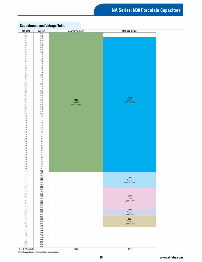
NA Series: N30 Porcelain Capacitors
Capacitance and Voltage TableCAP CODE CAP (pF) CASE SIZE C11 0505 CASE SIZE C17 1111
0R1 0.1
150VCode 8
DWV = 375V
0R2 0.20R3 0.3
1000VCode 7
DWV = 2500V
0R4 0.40R5 0.50R6 0.60R7 0.70R8 0.80R9 0.91R0 1.01R1 1.11R3 1.31R4 1.41R5 1.51R6 1.61R7 1.71R8 1.81R9 1.92R0 2.02R1 2.12R2 2.22R4 2.42R7 2.73R0 3.03R3 3.33R6 3.63R9 3.94R3 4.34R7 4.75R1 5.15R6 5.66R2 6.26R8 6.87R5 7.58R2 8.29R1 9.1100 10110 11120 12130 13150 15160 16180 18200 20220 22240 24270 27300 30330 33360 36390 39430 43470 47510 51560 56620 62680 68750 75820 82910 91101 100111 110
500VCode 4
DWV = 1250V
121 120131 130151 150161 160181 180201 200221 220
200VCode 6
DWV = 500V
241 240271 270301 300331 330361 360391 390431 430471 470511 510 100V
Code 1DWV = 250V
561 560621 620681 680
50VCode 5
DWV = 125V
751 750821 820911 910102 1000122 1200152 1500182 1800222 2200272 2700332 3300392 3900472 4700512 5100
Reel QTY Horizontal 3500 2350
Special capacitance values available upon request.

www.dilabs.com 26
UL Series: Ultra Low ESR Ceramic Capacitors
Dielectric Characteristics
Dielectric Material
Code
Temperature Coefficient
(ppm/°C Maximum)
Dissipation Factor
(% @ 1MHz Maximum)
Dielectric Withstanding Voltage Insulation Resistance(MΩ Minimum)
Aging PiezoelectricEffects
Dielectric Absorption Voltage Rating
(Volts)DWV
(Volts) @ +25°C @ +125°C
UL 0 ± 30 0.05Please see
chart (pg. 25)
250% of WVDC for 5 sec unless
specified in chart(pg. 25)
105 104 None None None
Part Number Breakdown*
C 17 UL 620 J - 7 U N - X 0 TMulti Layer
Case Size Material System
Capacitance Code
Tolerance Level
Voltage Code
Termination Code
Leading Code
Test Level Marking Code
Packaging
Available Termination TypesC04 SC06 U, S, ZC07 U, S, ZC08 U, S, ZC11 U, S, ZC17 U, S, Z
Available Laser MarkingC04 0C06 0, 1, 2C07 0, 1C08 0, 1, 2C11 0, 1, 2C17 0, 1, 2
Available PackagingC04 T, W, B, P, SC06 T, W, B, P, SC07 W, B, P, SC08 T, V, W, B, P, SC11 T, V, W, B, P, SC17 T, V, W, B, P, SCode Termination System
U Ag Termination, Ni Barrier Layer, SnPb Plated Solder
S Ag Termination, Ni Barrier Layer, Gold Flash, RoHS
Z Ag Term., Ni Barrier Layer, Sn Plated Solder, RoHS
Code Laser Marking0 No marking1 Single-side
marked2 Double-side
marked9 Customer
Specified
Available Lead TypesC04 NC06 NC07 NC08 NC11 A, B, DC17 A, B, C, D, E, F
Test Level – All Case SizesX StandardY Reduced VisualA MIL-PRF-55681
Group AC MIL-PRF-55681
Group CD Customer
SpecifiedCode PackagingT Tape & Reel –
HorizontalV Tape & Reel –
VerticalW Waffle PackB BulkP Plastic BoxS Customer
Specified
Description
Ceramic Capacitors NPOLow ESR, High Q Capacitance Range 0.2 - 2200 pF High Working Voltage Low Noise
Functional Applications
DC BlockingAmplifier Matching NetworksVCO Frequency StabilizationFiltering, Diplexers & Antenna High RF Power Circuits Bypass Coupling Tuning & Feedback Broadcast Power Amps
Benefits
High Q Stable TC, -55° to +125°C Operating RangeEIA 0603 & 0805 Case Size SMD Compatibility Oscillators Timing Circuits Filters RF Power Amplifiers & Delay Lines Ultra Low ESR
*See page 6 for complete part number system.

27 www.dilabs.com
UL Series: Ultra Low ESR Ceramic Capacitors
Capacitance and Voltage TableCAP CODE CAP (pF) CASE SIZE C04 0402 CASE SIZE C06 0603 CASE SIZE C07 0711 CASE SIZE C08 0805 CASE SIZE C11 0505 CASE SIZE C17 1111
0R1 0.1
200VCode 6
DWV = 500V
250VCode 9
DWV = 625V
250VCode 9
DWV = 625V
1000VCode 7
DWV = 2500V
0R2 0.20R3 0.3
500VCode 4
DWV = 1250V
250VCode 9
DWV = 625V
0R4 0.40R5 0.50R6 0.60R7 0.70R8 0.80R9 0.91R0 1.01R1 1.11R2 1.21R3 1.31R4 1.41R5 1.51R6 1.61R7 1.71R8 1.81R9 1.92R0 2.02R1 2.12R2 2.22R4 2.42R7 2.73R0 3.03R3 3.33R6 3.63R9 3.94R3 4.34R7 4.75R1 5.15R6 5.66R2 6.26R8 6.87R5 7.58R2 8.29R1 9.1100 10110 11120 12130 13150 15160 16180 18200 20220 22240 24270 27300 30330 33360 36
200VCode 6
DWV = 500V
390 39430 43470 47510 51
250VCode 9
DWV = 625V
150VCode 8
DWV = 375V
560 56620 62680 68750 75820 82910 91101 100111 110
500VCode 4
DWV = 1250V
121 120151 150181 180221 220
200VCode 6
DWV = 500V
271 270331 330391 390471 470511 510 100V
Code 1DWV = 250V
561 560621 620681 680
50VCode 5
DWV =125V
821 820911 910102 1000
Reel QTY Horizontal 5000 4000 2350 5000 3500 2350
Special capacitance values available upon request.
www.dilabs.com 28
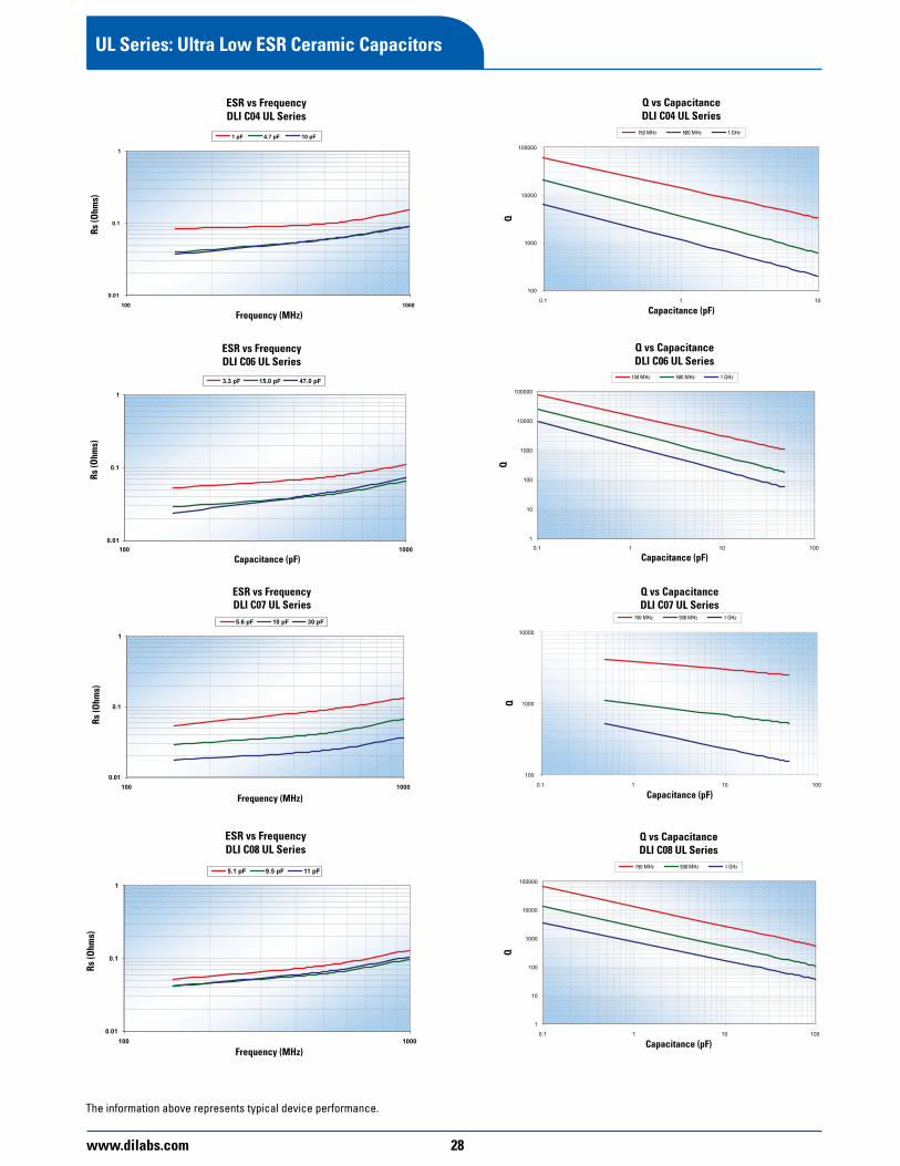
UL Series: Ultra Low ESR Ceramic Capacitors
The information above represents typical device performance.

29 www.dilabs.com
UL Series: Ultra Low ESR Ceramic Capacitors
The information above represents typical device performance.

www.dilabs.com 30
UL Series: Ultra Low ESR Ceramic Capacitors
The information above represents typical device performance.

31 www.dilabs.com
C04 ENGINEERING KIT10 Pieces Each of 15 Values
Code Cap 0R3 0.3pF 0R5 0.5pF 1R0 1.0pF 1R2 1.2pF 1R5 1.5pF 1R8 1.8pF 2R0 2.0pF 2R2 2.2pF 2R7 2.7pF 3R3 3.3pF 3R9 3.9pF 4R7 4.7pF 5R6 5.6pF 6R8 6.8pF 100 10pF C04 Broadband Block 120pF
C04 DESIGNER KIT10 Pieces Each of 8 Values
KIT C KIT D KIT E 0R1 0R9 3R9 0R2 1R0 4R7 0R3 1R2 5R1 0R4 1R5 5R6 0R5 1R8 6R8 0R6 2R2 8R2 0R7 2R7 9R1 0R8 3R3 100
C04, C06, C11 and C17 Kits
C06 ENGINEERING KIT10 Pieces Each of 21 Values
Code Cap 0R3 0.3pF 0R5 0.5pF 1R0 1.0pF 1R2 1.2pF 1R5 1.5pF 1R8 1.8pF 2R0 2.0pF 2R2 2.2pF 2R7 2.7pF 3R3 3.3pF 3R9 3.9pF 4R7 4.7pF 5R6 5.6pF 6R8 6.8pF 100 10pF 150 15pF 180 18pF 220 22pF 270 27pF 330 33pF 470 47pF C06 Broadband Block 850pF
C06 DESIGNER KIT10 Pieces Each of 10 Values
KIT C KIT D KIT E 0R1 1R2 6R8 0R2 1R5 8R2 0R3 1R8 9R1 0R4 2R2 100 0R5 2R7 120 0R6 3R3 150 0R7 3R9 220 0R8 4R7 270 0R9 5R1 360 1R0 5R6 470
C11 ENGINEERING KIT10 Pieces Each of 28 Values
Code Cap 0R3 0.3pF 0R5 0.5pF 0R7 0.7pF 1R0 1.0pF 1R2 1.2pF 1R5 1.5pF 1R8 1.8pF 2R0 2.0pF 2R2 2.2pF 2R7 2.7pF 3R3 3.3pF 3R9 3.9pF 4R7 4.7pF 5R6 5.6pF 6R8 6.8pF 8R2 8.2pF 100 10pF 120 12pF 150 15pF 180 18pF 270 27pF 330 33pF 390 39pF 470 47pF 560 56pF 680 68pF 820 82pF 101 100pF C08 Broadband Block 2400pF
C11 DESIGNER KIT10 Pieces Each of 10 Values
KIT C KIT D KIT E KIT F OR1 1R0 5R6 270 0R2 1R2 6R8 330 0R3 1R5 8R2 390 0R4 1R8 100 470 0R5 2R2 120 510 0R6 2R7 150 560 0R7 3R3 180 620 0R8 3R9 220 680 0R9 4R7 270 820 1R0 5R1 330 101
C17 ENGINEERING KIT10 Pieces Each of 35 Values
Code Cap 0R3 0.3pF 0R5 0.5pF 0R7 0.7pF 1R0 1.0pF 1R2 1.2pF 1R5 1.5pF 1R8 1.8pF 2R0 2.0pF 2R2 2.2pF 2R7 2.7pF 3R3 3.3pF 3R9 3.9pF 4R7 4.7pF 5R6 5.6pF 6R8 6.8pF 8R2 8.2pF 100 10pF 120 12pF 150 15pF 180 18pF 220 22pF 270 27pF 330 33pF 390 39pF 470 47pF 560 56pF 680 68pF 820 82pF 101 100pF 151 150pF 221 220pF 331 330pF 471 470pF 681 680pF 102 1000pF C08 Broadband Block 2400pF
C17 DESIGNER KIT10 Pieces Each of 10 Values
KIT C KIT D KIT E KIT F 0R1 1R0 5R6 390 0R2 1R2 6R8 470 0R3 1R5 8R2 560 0R4 1R8 100 680 0R5 2R2 120 820 0R6 2R7 150 101 0R7 3R3 180 221 0R8 3R9 220 471 0R9 4R7 270 681 1R0 5R1 330 102
DLI reserves the right to substitute values as required. Customers may request particular cap value and material for sample kit to prove out designs.Custom kits available upon request.

www.dilabs.com 32
C04/C06/C08 Broadband Blocks
Functional ApplicationsFiber Optic Links, High Isolation Decoupling, LAN’s, VCO Frequency Stabilization, Diplexers, RF/Microwave Modules, Instruments and Test Equipment.
BenefitsResonance free DC Blocking / Decoupling, Less than 0.25 db loss @ 4 GHz (typical), Surface mountable
Mechanical Specification
L
T
W
T
B
ProductCode
Body Dimensions Band Dimensions (B)
Length (L) Width (W) Thickness (T) Min Max
C04BL 0.040" ± 0.008"
0.020" ± 0.006" 0.028" Max 0.003" 0.019"
C06 BL 0.060" ± 0.012"
0.031" ± 0.009" 0.036" Max 0.006" 0.03"
C08 BL 0.081" ± 0.020"
0.051" ± 0.013" 0.061" Max 0.012" 0.0468"
Performance
Part NumberCapacitanceGuaranteed
Minimum Value
Voltage Rating
TemperatureCoefficient
-55°C to 125°C
MaximumDissipation
Factor
InsulationResistance
(MΩ Minimum)
AgingRate
FrequencyRange Termination
C04BL121X-5UN-X0T 120pF @1KHz,.2Vrms 50 Vdc
± 15%3.0%@1KHz,
.2Vrms104
<=1.5%/decadehours
10MHz – 40GHz “U” & “S”
C06BL851X-1UN-X0T 850pF @ 1KHz,.2Vrms 100 Vdc 2MHz – 30GHz “U”, “S” & “Z”
C08BL242X-5UN-X0T 2400pF @1KHz,.2Vrms 50 Vdc 1MHz – 20GHz “U”, “S” & “Z”
C08BL102X-1UN-X0T 1000pF @1KHz,.2Vrms 100 Vdc 1MHz – 20GHz “U”, “S” & “Z”
Part Characteristics
C06BL851X-1UN-X0T Insertion Loss (S21)
-2
-1.8
-1.6
-1.4
-1.2
-1
-0.8
-0.6
-0.4
-0.2
0
0 2 4 6 8 10 12 14 16 18 20
Frequency (GHz)
S21
(dB
)
The information above represents typical device performance.

33 www.dilabs.com
Opti-Cap®
Functional Applications• Improved Low Frequency Stability over Temperature• Very Low Series Inductance• X7R Temperature and Voltage Stability
Electrical Characteristics
Opti-Cap™ Electrical Characteristics
Part Number (Includes T&R)
Capacitance/ MLC Case
Size
Voltage Rating
Temperature Coefficient
IR (@+20°C,
Rated Voltage)
Max DF
1kHz
Aging Rate (% per Decade
Hour Max)Term
Frequency Range
3dB pts. Typical
Max Process Temperature
Recom-mended
Attachment Method
P62BN820MA2636 100 nF / 0603 25 VdcX7R
∆C max: ±15% (-55ºC to 125ºC)
102 MΩ 3.0% 1.0% Au (Flash)
16 KHz >>40 GHz
250°C/ Conductive
Epoxy or Solder
P42BN820MA3152 220 nF / 0402 10 VdcX5R
∆C max: ±15% (-55ºC to 85ºC)
102 MΩ 3.5% 1.0% Au (Flash)
16 KHz >>40 GHz
250°C/ Conductive
Epoxy or Solder
P21BN300MA3976 10 nF / 0201 10VdcX5R
∆C max: ±15% (-55ºC to 85ºC)
102 MΩ 3.5% 1.0% Au (Flash)
16 KHz >>40 GHz
250°C/ Conductive
Epoxy or Solder
Notes:1. Termination Metalization: 7.5 ± 4.5 micro inches Au over 50 microinches Ni min.2. Maximum assembly process temperature: 250°C3. For best high frequency performance, attach surface A to transmission line. For 50 ohm system, transmission line should be near or slightly greater than 20 mils. Recommended microstrip gap length is 0.015 inch.4. Rated working voltage (WVDC) is the lesser of 25 volts (Milli.) or multilayer WVDC from Table B.5. Recommended attachment is solder or conductive epoxy.
Broadband KitPart Number Freq RangeP62BN820MA2636P02BN820Z5S 20MHz - 40GHzP02CG1R5C5S 8GHz - 32GHzP02CG1R0C5S 18GHz - 40GHzP02CF0R5B5S 28GHz - 40GHzP02CF0R3B5S 35GHz - 50GHzC06BL851X-1UN-X0B 2MHz - 30GHzC08BL242X-5UN-X0B 1MHz - 20GHz
Physical Characteristics
Benefits• Resonance Free DC Blocking to >40GHz• Surface Mountable by Solder or Epoxy Bonding• Available in Tape & Reel or Waffle Pack Format• Improved Low Frequency Stability over Temperature

www.dilabs.com 34
Milli-Cap® SMD Millimeter Wave Capacitor
Functional Applications0402, 0502 and 0602 Footprints, Very Low Series Inductance, Ultra High Series Resonance, Low Loss High Q part.
BenefitsMatches typical 50Ω Line Widths, Preserves Board Space, Behaves Like An Ideal Capacitor, More Usable Bandwidth
.020” ± .002” (.508 ± .05 mm)
.020” ± .002” (.508 ± .05 mm)
.043” - .058” (1.1 - 1.5 mm) Mechanical Specification
• Terminations: Gold
• Assembly temperatures not to exceed 260°C.
• Ideal for Test Equipment, Photonics, SONET, Digital radios, and Matching Filter applications
Part Characteristics
Part Number Cap. Voltage Rating
TemperatureCoefficient
-55°C to 125°C
MaximumDissipation
Factor
InsulationResistance
(MΩ Minimum)Aging Rate Frequency Range
P_2BN820Z5ST 82 pF
50 Vdc
± 10%3.0%@1MHz,25°C
105 MΩ @ 25°C at rated voltage
<=1.5%/decadehours
20MHz– 40GHz
P_2NR3R0K5ST 3.0 pF N1500±500PPM / °C
0.25%@1MHz,25°C
106 MΩ @ 25°C at rated voltage N / A*
4–20GHz
P_2CG1R5C5ST 1.5 pF0 ± 30PPM
0.7%@1KHz,25°C
8–32GHz
P_2CG1R0C5ST 1.0 pF 18–40GHz
P_2CD0R7B5ST 0.7 pF N20±15PPM / °C
0.15%@1MHz,25°C
20–46GHz
P_2CF0R5B5ST 0.5 pF0
±15PPM / °C
0.6%@MHz,25°C
28–40GHz
P_2CF0R3B5ST 0.3 pF 35–50GHz
Electrical Performance
Dimensions Key: P42 = 0402; P02 = 0502; P62 = 0602
The information above represents typical device performance.

35 www.dilabs.com
Functional ApplicationsBroadband Fiber Optic Links, LAN’s, Broadband and RF/Microwave Modules, Broadband High Isolation Decoupling, Broadband Instrumentation and Test Equipment
BenefitsResonance Free DC Blocking from 1 MHz to 20 GHz, Surface Mountable 0805 Case Size for Edge Mounting on 25mil Microstrip
DLI’s new web based CapCad™ capacitor modeling software was developed to provide customers with an easy to use and readily accessible comparison tool for choosing the best Single-Layer, Multi Layer or Broadband Blocking capacitor to suit the customer’s needs. CapCad™ includes SPICE models with values that reflect typical performance at the chosen frequencies and temperatures that are of importance to an application. The user also has the ability to plot 2-port Scattering Parameters, Impedance, Q Factor or Equivalent Capacitance over any frequency span from 1 MHz to 40 GHz while maintaining the ability
Multilayer Capacitors (DC Blocks)
CapCad™
to adjust the temperature and note how it may affect the performance. CapCad™ also includes a Smith Chart utility and the ability to copy the S-Parameter data in touchtone format(s2p).
The data presented by CapCad™ is based off of calculated models and is a representation of typical performance. It should not be construed as a specification or guarantee of performance. Actual performance may vary slightly from application to application. For more info or support please feel free to contact us by phone at (315) 655-8710, or by email at [email protected] .
Part Number: C04 BL 121 X - 5 S N - S
Size = 04W = 0.051 ± 0.006L = 0.040 ± 0.008T = 0.000 Max in. mm
Material = BLClass/TC = 1/±15%Cap (pF) = 120Voltage = 50Tolerance = X: GMVTermination = S: Standing Axial Beam LeadLeading = N: NoneTest Code = S: Special
Graphing Links
Series Shunt T-LineSeries Shunt T-Line
AH Series: P90 Porcelain Capacitors
CF Series: Ultrastable Porcelain Capacitors
NA Series: N30 Porcelain Capacitors C04/C06/C08
Broadband Blocks

www.dilabs.com 36
Other DLI Product Lines
Single Layer Capacitors
Di-Cap® Border Cap® Gap Cap Bar Cap® Binary Cap T-Cap®
Highest performance SLC for RF, MW and MMW applicationsfrom 100 MHz to 100 GHz.Most cap for size0.02 – 4300 pF
SLC w 1- or 2-sided recessed metallization to minimize the potential for shorting during die attach.Ideal for epoxy attach.0.02 – 1500 pF
Series configured precision SLC for elimination of wire-bonds and microstrip applications. Minimum performance variation.
Multiple decoupling/bypass or blocking SLC configured in a single array. 1-13 GHz. Ideal for decoupling MMICs.
Multi-value – binary tunable SLC for design tuning or MIC hybrids.
DiCap® SLC used in series connected open circuited transmission line- designed for repeatable resonance behavior.
Equalizers/Duplexers/Resonators
Gain Equalizer Duplexers and Diplexers Cavity Resonator
Excellent, repeatable microwave performance is achieved by application of precision thin film fabrication and DLI HI-K ceramic materials. DLI’s unique design solution provides near ideal R-C frequency response, far superior to “Stacked R-C chip” assemblies. RADAR application to 67 GHz.
Duplexers are three port devices used to separate and combine frequencies, having two filters with a common driving point covering two frequency bands. Diplexers are three port devices used to separate and combine frequencies, having one filter covering all frequency bands.
DLI’s Cavity Resonators set a new standard for high Q resonator performance across a broad spectrum of frequencies. High Q resonators play a critical role in system noise performance, and employing the advantage is dramatically easier and less expensive than ever before. These products include extremely stable Single Frequency Cavity Resonators (SFCR), Narrow-Band and Wide-Band Tunable Ceramic Resonator, and Two-Port Resonators. Single Frequency Cavity Resonators-standard from 3GHz to >67GHz. Two Port Cavity Resonators-standard from 3GHz to >67Ghz.
Filter Family Bias Filter Network Heatsinks, Sub Mounts and Standoffs Build to Print
Micro-strip, cavity filters, duplexers, diplexers, GPS filters. Frequency from 500 MHz to 67 GHz. No tuning required, extremely temperature stable, miniature and lightweight. Customized designs and prototypes.
Designed to filter RF signals from bias and control line from 10MHz to 40GHz. Reduces RF feedback through bias supplies and simplifies assembly – one component replaces many.
For laser diodes, VCSEL, and others for the fiber optics industry. DLI can customize a design for high volume and be very price competitive. The next generation of “smart” heatsinks are also available using proprietary technologies.
DLI maintains an inventory of industry standard ceramics and manufactures a large selection of proprietary and/or patented custom ceramics. Plus, DLI’s custom ceramics can offer significantly better thermal performance than the majority of industry standard ceramics and have the added benefit of a sufficiently higher K allowing miniaturization opportunities.
Filters/Heat Sinks/Sub Mounts/Standoffs
Substrates
DLI manufactures and/or procures substrates to allow our customers to manufacture their own custom ceramic products*. DLI’s proprietary and/or patented ceramics offer high K values, to allow for miniaturization, extreme temperature stability, space reliability and radiation hardened properties. As a direct result of the above, DLI is able to offer our customers a complete array of fabrication services for all industry standards and/or custom ceramics.
*DLI does restrict certain proprietary materials in specific applications for internal use only.
37 www.dilabs.com
Notes

www.dilabs.com 38
© C
opyr
ight
CM
P 20
10
- d
esig
n -
crea
tions
@pa
npub
licity
.co.
uk
Ceramic & Microwave Products (CMP) designs, manufactures and sells special electronic components and systems, including high-performance filters, switches, capacitors and EMI and cosite signal interference solutions. Our products are used in military, space, telecom infrastructure, medical and industrial applications where function and reliability are crucial.www.dovercmp.com
Dielectric Laboratories, Inc2777 Route 20 East, Cazenovia, NY 13035 USA
Phone: +1 315 655 8710 Fax: +1 315 655 0445
Email: [email protected]
Dow-Key Microwave4822 McGrath Street, Ventura, CA 93003 USA
Phone: +1 805 650 0260Fax: +1 805 650 1734
Email: [email protected]
K&L Microwave2250 Northwood Drive, Salisbury, MD 21801 USA
Phone: +1 410 749 2424Fax: +1 443 260 2268
Email: [email protected]
Novacap25111 Anza Drive, Valencia, CA 91355 USA
Phone: +1 661 295 5920 Fax: +1 661 295 5928
Email: [email protected]
Pole/Zero Corporation5558 Union Centre Drive, West Chester, OH 45069 USA
Phone: +1 513 870 9060 Fax: +1 513 870 9064
Email: [email protected]
Syfer Technology Limited Old Stoke Road, Arminghall, Norwich, NR14 8SQ UK
Phone: +44 1603 723300 Fax: +44 1603 723301
Email: [email protected]
Voltronics Corporation 100-10 Ford Road, Denville, NJ 07834 USA
Phone: +1 973 586 8585 Fax: +1 973 586 3404
Email: [email protected]
June 2010
BSC Filters Ltd,Jorvik House, Outgang Lane, Osbaldwick, York YO19 5UP UK
Phone: +44 1904 438438 Fax: +44 1904 438123
Email: [email protected]
IMS
775
911
Nov 2011 R/2

![Solid Tantalum Surface Mount Chip Capacitors ANTAMOUNT ... · V 7343-20 0.287 ± 0.012 [7.3 ± 0.30] 0.169 ± 0.012 [4.3 ± 0.30] 0.079 max [2.0 max] 0.051 ± 0.012 [1.3 ± 0.30]](https://img.pdfslide.us/doc/110x75/5fb399b2033ed705fe72d607/solid-tantalum-surface-mount-chip-capacitors-antamount-v-7343-20-0287-0012.jpg)