Embed Size (px)
Citation preview
Bailey V5 Paramotor Manual V1.0
Welcome Congratulations on the purchase of your Bailey V5 paramotor, please thoroughly read this owners manual before proceeding to assemble or start your new paramotor unit. Every care has been taken to make this manual as accurate and instructive as possible and all data and procedures are correct at the time of printing. However Bailey Aviation reserve the right to make specification and detail changes to any part of their equipment, manufacturing processes or this manual without recourse. For the latest version of this manual, please visit the download section of our website at www.baileyaviation.com. This manual covers the component parts of your new machine, the assembly, running-in, starting/stopping procedures and to offer guidelines on maintenance and proper up-keep of your Bailey V5 paramotor. Whilst we list pre-flight checks, this manual is NOT a substitute for professional training. We strongly advise that you seek fully professional training and obtain any licence or aviation clearance necessary to fly a Bailey V5 in your country. We wish you many happy hours with your new paramotor.
Manual Contents
Page No Description 1 Introduction & Description 2 Specification 3 Components & Dimensions 4 Pre-flight checks & Warnings 5 Assembly (cage & propeller) 6 Assembly (harness, hang bars & fuel tank) 7 Operation Notes / Running-in / Starting 8 Adjustments & Set-up 9 Service Schedule 10 Maintenance Procedures (oil & filter) 11 Maintenance Procedures (drive belt & valve clearances) 12 Wiring Diagram 13 Parts List 14 Warranty / Disclaimer 15 Notes
Paramotor Supplied Parts
Your Bailey V5 paramotor is supplied as the following component parts:
1 x Chassis assembly with engine 1 x Harness 1 x 11.5 Litre plastic fuel tank 1 x Padded Cage Bag 4 x Cage Quarters 1 x Pr Propeller covers 2 x Active Hang Bars 1 x User manual 1 x Helix 1.30m propeller
Bailey V5 Paramotor Manual V1.0 Page 1
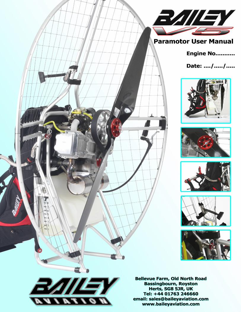
Paramotor Introduction The Bailey V5 paramotor is designed, manufactured and assembled in the U.K. to exacting standards. The alloy cage and engine chassis are made from drawn aviation specification aluminium tube of various gauges giving maximum structural stiffness without adding excess weight. All tubes are precision TIG welded using filler rod of the same material to insure uniform strength and quality of finish, with corrosion resistant anodised finish. In the event of a very heavy landing or fall the cage is designed to deform & absorb impact, protecting the pilot and the main chassis. This ‘No compromise’ design has high structural rigidity in key stressed areas and is designed to be dismantled quickly & easily, leaving the chassis/engine to remain free standing when disassembled. Our all new ‘Active Chassis System’ has been completely re-designed offering enhanced weight-shift ability and extensive flight testing by many different size/weight pilots has proved that the system not only remains vertically stable with large or small power changes but also exhibits virtually zero torque steer. Our latest 11.5L plastic fuel tank is mounted higher on the chassis than our previous designs and provides a clear airflow path under the seat and into the prop arc, making the machine more aerodynamic and giving a higher Centre of Gravity (CofG), making the V5 feel lighter on the ground. The translucent tank allows you to easily see the fuel level, is quick release and features a convenient carrying strap for re-fuelling walks on bivouac trips.
Engine Description The V5 is the fifth generation of the world championship-winning Bailey Aviation 4-stroke engine, offering smooth, progressive power with low noise levels and superior fuel consumption. The culmination of 10 years producing engines, the V5 is our lightest and most compact design, offering effortless pull starting and a wide power band from idle to maximum RPM. The Bailey V5 engine is a lightweight single cylinder 4-stroke engine with the unique ‘Bailey Easy Start System’ (BESS). This System enables the high compression V5 to be easily pull started by releasing 80% of the compression during cranking. Once started the system automatically disengages. The V5 features a 2-piece CNC machined cast alloy crankcase, has a capacity of 195cc with two valves operated by a chain driven overhead camshaft. The oil system is fully pressurised with a pressure relief valve thus maintaining constant oil pressure regardless of the oil temperature or RPM. The cylinder bore features a special coating for increased wear resistance and the crankshaft design features oversize bearings and an internal needle-roller bearing. The crankshaft runs on two main bearings with a third bearing to accommodate drive belt loads. The integral prop speed reduction unit (PSRU) is driven via a Poly-V belt with eccentric belt tension adjustment. Ignition is CDI (capacitive discharge) with integrated variable advance curve. Carburation is by float type carburettor (CVK26) with a K&N air filter with rubber mounted anti-vibration bracket, fitted to any alloy inlet manifold. Engine cooling is taken care of by our forced air cooling system, using a crankshaft mounted fan, ducted around the cylinder and head by our all-new injection moulded engine cowling, which also neatly houses the pulse fuel pump. The ignition CDI unit is also directly mounted to the engine on a custom bracket, making for an incredibly neat installation. The engine has a 3 stage oil filtering system, with a replaceable oil filter that is easy accessible and a glass oil level window so you can easily check the oil level. The exhaust silencer and downpipe are made from 304 Stainless steel for longevity, with a chrome plated engine-mounted mild steel exhaust bracket which houses our heavy duty sprung exhaust mounting clamps to allow for thermal expansion/contraction of the exhaust under all engine temperatures. Every V5 paramotor is fully tested on our in-house test-rig prior to being signed off for customer release.
Bailey V5 Paramotor Manual V1.0 Page 2
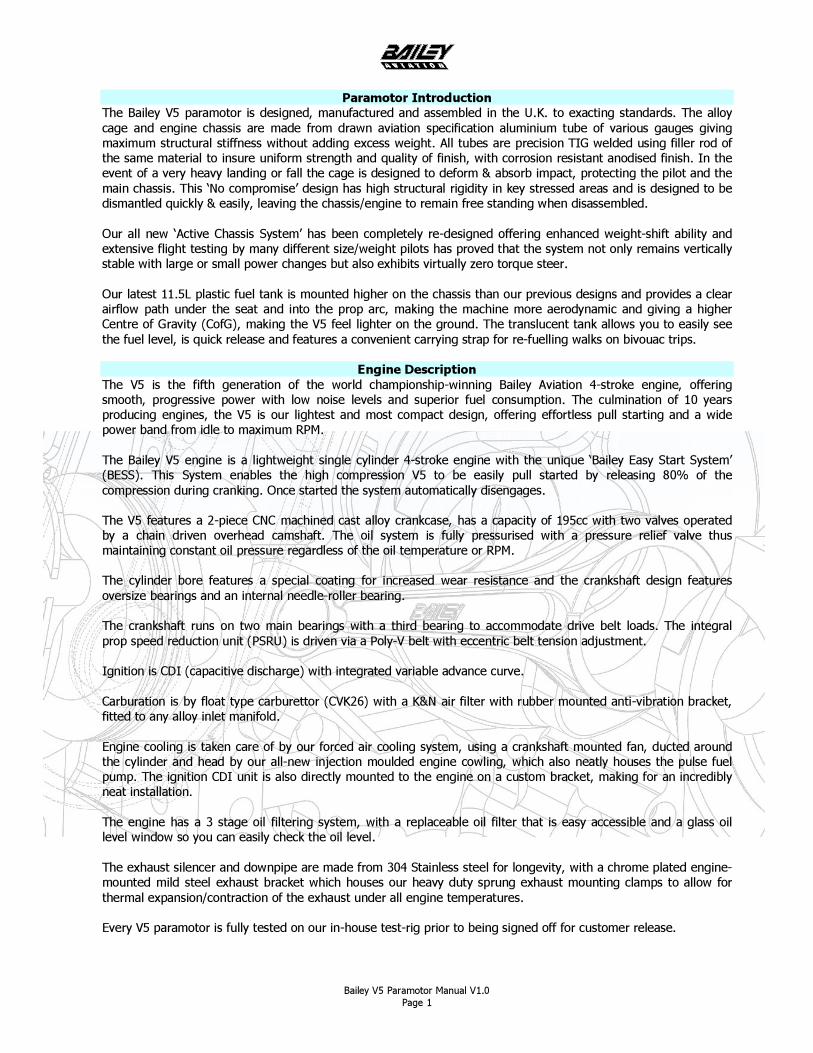
V5 Engine Specification Manufacturer Bailey Aviation, United Kingdom Type Single cylinder 4 stroke, forced air cooled, 2 valve per cylinder, cast alloy. Displacement 195cc Bore/Stroke 65x59mm Crankshaft 3 Bearing roller Piston Forged alloy, 3 ring Oil System Wet sump with pressure pump and 3 way oil filtration and P.R.V. Fuel system CVK float bowl carburettor with pulse pump PRSU/Reduction 3.19:1 reduction with poly-V drive Prop Mounting 6 x 75mm PCD M8 studs or BQRP single bolt + ‘R’ Clip Exhaust Stainless steel Starter Manual pull start with rope rewind (recoil) Ignition System Variable advance CDI Oil Capacity 500cc Oil Type Fully Synthetic 10W40 or 10W60 4 stroke motorcycle oil
(Putoline Off Road Nanotech 4+ 10w/60 recommended) (Spec – JASO – MA2 –API –SL)
Mountings 4 x M8 bonded rubber ‘Silent blocs’ Spark Plug type NGK CH7SA (or equivalent) Spark Plug Gap 0.60mm (0.24”) Air filter K&N R-1070 Oil Filter Pleated paper (order from Bailey Aviation) Drive belt tension 5-8mm Deflection at mid span point with 10Kg force Valve clearances 0.10mm (0.004”) for inlet and exhaust valves Fuel Type 95-99 (Ron) Octane unleaded fuel, AVGAS not recommended
V5 Engine Performance & Limitations Power Output 20.5hp @ 8200 RPM Thrust Output (Static) >60Kg when used with recommended Helix 1.30m propeller Max Power RPM Limited to 5 minutes Max Continuous RPM 7500 RPM Oil Temp Max 180ºC Min 50ºC Cyl Head Temp Max 220ºC Min 50ºC
V5 Paramotor
Empty Weight 27.5Kg Fuel Tank Capacity 11.5L (Quick release plastic fuel tank)
Bailey V5 Paramotor Manual V1.0 Page 3
A
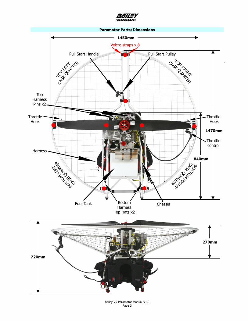
Paramotor Parts/Dimensions
1450mm
1470mm
840mm
270mm
720mm
Bailey V5 Paramotor Manual V1.0 Page 4
Pre-Flight Checks - Warnings Engine Oil Level - With paramotor placed on a flat surface the oil level should be between the half way (min) and top (max) of the glass oil window.
Fuel System - Ensure you have sufficient fuel for the planned flight, that the tank is secured to the chassis (check two retaining bolts) and that the tank cap is tight. Also check that the dry-break fuel couplings and fuel lines are tight and leak free. Exhaust System - Ensure exhaust system is secure, check swivel springs at both ends of the downpipe and also the condition of the T-bolt clamps. DO NOT tighten T-bolt clamp nyloc nuts, these are factory pre-set to provide optimum clamping force, whilst allowing for sufficient expansion/contraction of exhaust assembly (There must be a 0.5mm gap between each coil of the springs – See page 8 for more details).
Air Filter / Carburettor - Ensure that air filter is in good condition, tightened securely and is not soiled or blocked. Check securing bracket is in good condition and fastened correctly. Check the condition of the rubber connector between carburettor and inlet manifold and that the two constant tension spring clips are located correctly. Spark Plug HT Lead – Check that the HT lead cap is fully pushed onto the plug. It is not necessary to remove/check spark plug before each flight (this is not a 2 stroke engine!). Repeated unnecessary removal of the spark plug cap will cause it to become loose.
Cooling Air Inlet - Ensure there is no restriction to air entering the cooling fan inlet
Throttle Assembly - Visually check for full throttle travel on the carburettor and ensure throttle closes fully and smoothly.
Cage Quarters/Netting - Check that all 4 cage quarters are correctly located to each other and the chassis. Visually check nylon netting for damage and tightness.
Cage Straps - Ensure that all Velcro Cage straps are in good condition and are secured very tightly (they must have tension, not slack).
Reduction Drive / Propeller - Check that propeller is free from cracks and chips. Check the six securing studs/nuts are tightened to the specific torque setting (7lbs/ft [10nm]). If BQRP single bolt system is fitted, check bolt is tightened to specific torque setting (10-15lbs/ft [14-21nm]) and that safety ‘R’ clip is fitted. Turn propeller by hand (make sure master switch is off) in either direction through a full 360º rotation and check for sufficient clearance of all components. Minimum clearance from propeller tip to cage should be 50mm. Drive Belt – Check the Poly-V drive belt for cracks or wear
Harness - Visually check all harness connections and examine harness for signs of damage/fraying etc. Make sure all pockets are zipped tight
Hang Bars - Check tightness of all hang bar to harness connections and make sure the hang bar red securing nuts are tight and have their ‘R’ Clips fitted correctly.
Ground Running - Bailey Aviation recommend that you DO NOT ‘Ground run’ the engine. Experience has proven that the ONLY safe place to run a paramotor engine is with it firmly strapped on your back or secured to a purpose made test rig. All pre-flight power checks are best performed whilst wearing the paramotor on your back. This is much safer and prevents stones or debris being drawn into the propeller.
Before proceeding to check over your machine, make sure that the master switch is in the ‘OFF’ position. The Bailey Easy Start System (BESS) makes the engine very easy to start - Remember always safety first !
Propellers can be very dangerous, DO NOT start engine where there is any chance of the propeller coming into contact with the operator or any other person or object.
Bailey V5 Paramotor Manual V1.0 Page 5
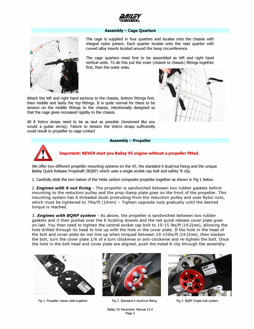
Assembly – Cage Quarters
Assembly – Propeller
We offer two different propeller mounting systems on the V5, the standard 6 stud/nut fixing and the unique Bailey Quick Release Propshaft (BQRP) which uses a single socket cap bolt and safety ‘R clip. 1. Carefully slide the two halves of the Helix carbon composite propeller together as shown in Fig 1 below.
2. Engines with 6 nut fixing - The propeller is sandwiched between two rubber gaskets before mounting to the reduction pulley and the prop clamp plate goes on the front of the propeller. This mounting system has 6 threaded studs protruding from the reduction pulley and uses Nyloc nuts, which must be tightened to 7lbs/ft (10nm) – Tighten opposite nuts gradually until the desired torque is reached.
3. Engines with BQRP system - As above, the propeller is sandwiched between two rubber gaskets and it then pushes over the 6 locating dowels and the red quick release cover plate goes on last. You then need to tighten the central socket cap bolt to 10-15 lbs/ft (14-21nm), allowing the hole drilled through its head to line up with the hole in the cover plate. If the hole in the head of the bolt and cover plate do not line up when torqued between 10-15lbs/ft (14-21nm), then slacken the bolt, turn the cover plate 1/6 of a turn clockwise or anti-clockwise and re-tighten the bolt. Once the hole in the bolt head and cover plate are aligned, push the metal R clip through the assembly.
The cage is supplied in four quarters and locates onto the chassis with integral nylon joiners. Each quarter locates onto the next quarter with curved alloy inserts located around the hoop circumference. The cage quarters need first to be assembled as left and right hand vertical units. To do this put the inner (closest to chassis) fittings together first, then the outer ones.
Important: NEVER start you Bailey V5 engine without a propeller fitted.
Fig 1. Propeller halves slide together Fig 2. Standard 6 stud/nut fitting Fig 3. BQRP Single bolt system
Attach the left and right hand sections to the chassis, bottom fittings first, then middle and lastly the top fittings. It is quite normal for there to be tension on the middle fittings to the chassis, intentionally designed so that the cage gives increased rigidity to the chassis. All 8 Velcro straps need to be as taut as possible (tensioned like you would a guitar string). Failure to tension the Velcro straps sufficiently could result in propeller to cage contact
Bailey V5 Paramotor Manual V1.0 Page 6
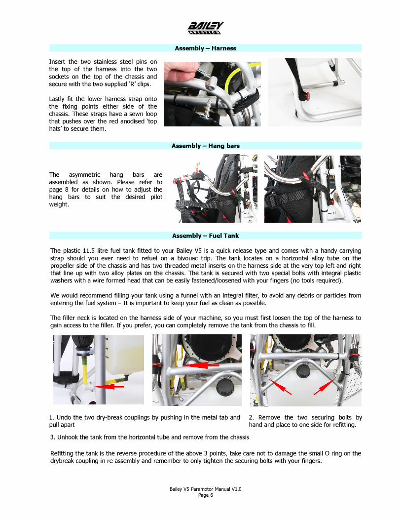
Assembly – Harness
Assembly – Hang bars
Assembly – Fuel Tank The plastic 11.5 litre fuel tank fitted to your Bailey V5 is a quick release type and comes with a handy carrying strap should you ever need to refuel on a bivouac trip. The tank locates on a horizontal alloy tube on the propeller side of the chassis and has two threaded metal inserts on the harness side at the very top left and right that line up with two alloy plates on the chassis. The tank is secured with two special bolts with integral plastic washers with a wire formed head that can be easily fastened/loosened with your fingers (no tools required). We would recommend filling your tank using a funnel with an integral filter, to avoid any debris or particles from entering the fuel system – It is important to keep your fuel as clean as possible. The filler neck is located on the harness side of your machine, so you must first loosen the top of the harness to gain access to the filler. If you prefer, you can completely remove the tank from the chassis to fill. Refitting the tank is the reverse procedure of the above 3 points, take care not to damage the small O ring on the drybreak coupling in re-assembly and remember to only tighten the securing bolts with your fingers.
Insert the two stainless steel pins on the top of the harness into the two sockets on the top of the chassis and secure with the two supplied ‘R’ clips. Lastly fit the lower harness strap onto the fixing points either side of the chassis. These straps have a sewn loop that pushes over the red anodised ‘top hats’ to secure them.
1. Undo the two dry-break couplings by pushing in the metal tab and pull apart
2. Remove the two securing bolts by hand and place to one side for refitting.
3. Unhook the tank from the horizontal tube and remove from the chassis
The asymmetric hang bars are assembled as shown. Please refer to page 8 for details on how to adjust the hang bars to suit the desired pilot weight.
Bailey V5 Paramotor Manual V1.0 Page 7
Operation Ensure propeller cannot contact anything or anyone. (In the case of a paramotor, machine must either be 1. Securely strapped to a pilot or 2. Securely fixed to proprietary test rig.)
DO NOT start your paramotor unless one of these 2 rules is obeyed.
Running-in Your V5 engine has been fully tested prior to customer release, but you must adhere to the following procedure to ensure no damage is caused to your engine in the first few critical running hours. After the first 10 running hours, your engine will be run-in and you must perform an oil and filter change and check the valve clearance settings, as is shown on the service schedule on page 9. During the running-in period (first 10 hours) full power can be used for take-off. Once airborne power should be reduced to a maximum of 75%. Varying the engine RPM during this period is recommended. Running-in on the ground is strongly discouraged. This is much safer and prevents stones or debris being drawn into the propeller.
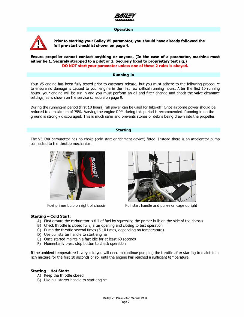
Starting The V5 CVK carburettor has no choke (cold start enrichment device) fitted. Instead there is an accelerator pump connected to the throttle mechanism. Starting – Cold Start:
A) First ensure the carburettor is full of fuel by squeezing the primer bulb on the side of the chassis B) Check throttle is closed fully, after opening and closing to test operation C) Pump the throttle several times (5-10 times, depending on temperature) D) Use pull starter handle to start engine E) Once started maintain a fast idle for at least 60 seconds F) Momentarily press stop button to check operation
If the ambient temperature is very cold you will need to continue pumping the throttle after starting to maintain a rich mixture for the first 10 seconds or so, until the engine has reached a sufficient temperature. Starting – Hot Start:
A) Keep the throttle closed B) Use pull starter handle to start engine
Prior to starting your Bailey V5 paramotor, you should have already followed the full pre-start checklist shown on page 4.
Fuel primer bulb on right of chassis Pull start handle and pulley on cage upright
Bailey V5 Paramotor Manual V1.0 Page 8
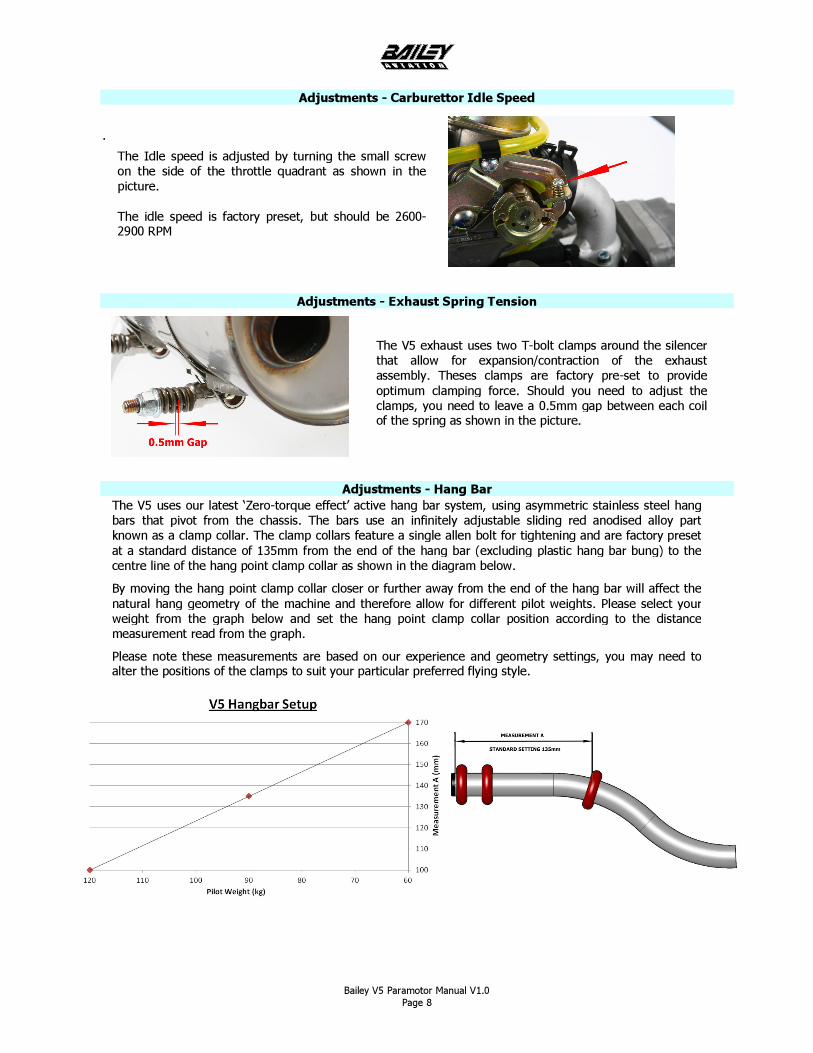
The V5 uses our latest ‘Zero-torque effect’ active hang bar system, using asymmetric stainless steel hang bars that pivot from the chassis. The bars use an infinitely adjustable sliding red anodised alloy part known as a clamp collar. The clamp collars feature a single allen bolt for tightening and are factory preset at a standard distance of 135mm from the end of the hang bar (excluding plastic hang bar bung) to the centre line of the hang point clamp collar as shown in the diagram below.
By moving the hang point clamp collar closer or further away from the end of the hang bar will affect the natural hang geometry of the machine and therefore allow for different pilot weights. Please select your weight from the graph below and set the hang point clamp collar position according to the distance measurement read from the graph.
Please note these measurements are based on our experience and geometry settings, you may need to alter the positions of the clamps to suit your particular preferred flying style.
Adjustments - Carburettor Idle Speed
.
Adjustments - Exhaust Spring Tension
Adjustments - Hang Bar
The V5 exhaust uses two T-bolt clamps around the silencer that allow for expansion/contraction of the exhaust assembly. Theses clamps are factory pre-set to provide optimum clamping force. Should you need to adjust the clamps, you need to leave a 0.5mm gap between each coil of the spring as shown in the picture.
The Idle speed is adjusted by turning the small screw on the side of the throttle quadrant as shown in the picture. The idle speed is factory preset, but should be 2600-2900 RPM
Bailey V5 Paramotor Manual V1.0 Page 9
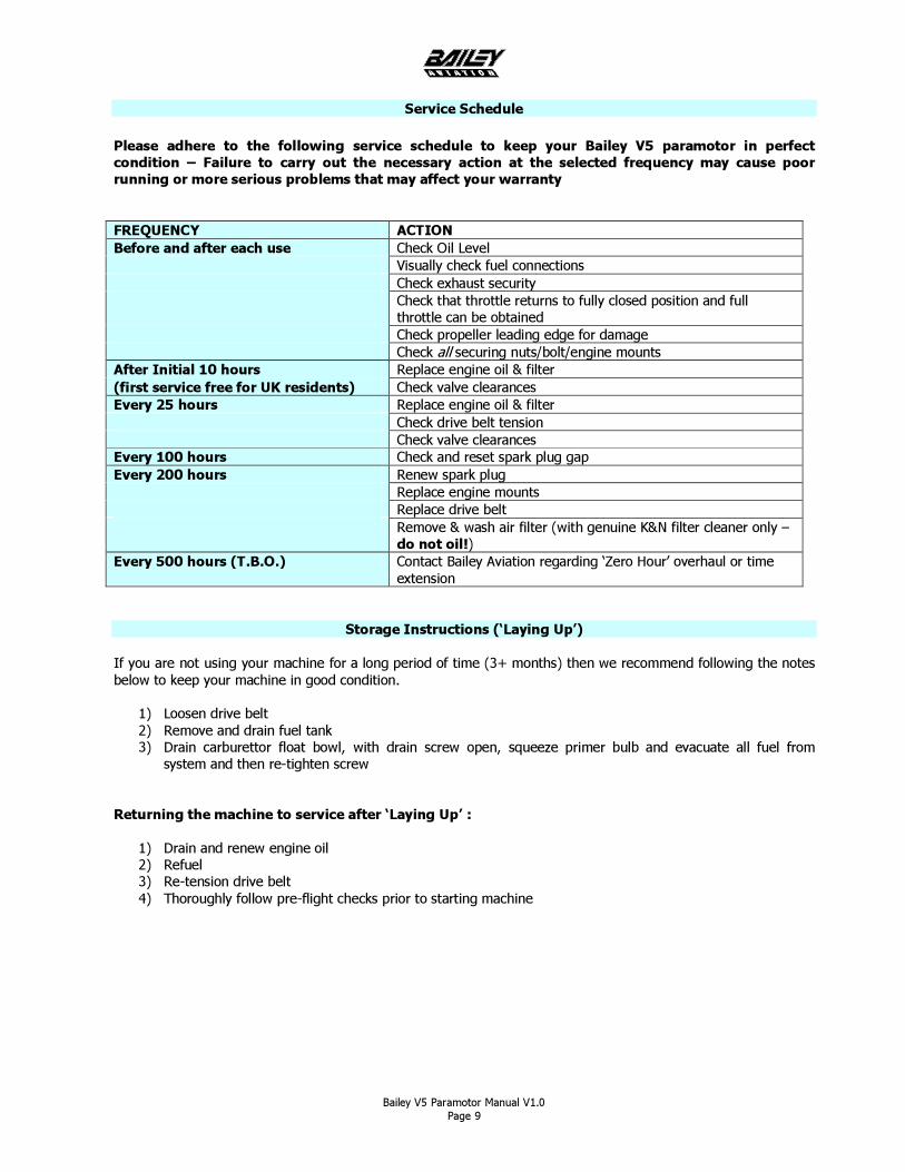
Service Schedule Please adhere to the following service schedule to keep your Bailey V5 paramotor in perfect condition – Failure to carry out the necessary action at the selected frequency may cause poor running or more serious problems that may affect your warranty FREQUENCY ACTION Before and after each use Check Oil Level Visually check fuel connections Check exhaust security Check that throttle returns to fully closed position and full
throttle can be obtained Check propeller leading edge for damage Check all securing nuts/bolt/engine mounts After Initial 10 hours Replace engine oil & filter (first service free for UK residents) Check valve clearances Every 25 hours Replace engine oil & filter Check drive belt tension Check valve clearances Every 100 hours Check and reset spark plug gap Every 200 hours Renew spark plug Replace engine mounts Replace drive belt Remove & wash air filter (with genuine K&N filter cleaner only –
do not oil!) Every 500 hours (T.B.O.) Contact Bailey Aviation regarding ‘Zero Hour’ overhaul or time
extension
Storage Instructions (‘Laying Up’) If you are not using your machine for a long period of time (3+ months) then we recommend following the notes below to keep your machine in good condition.
1) Loosen drive belt 2) Remove and drain fuel tank 3) Drain carburettor float bowl, with drain screw open, squeeze primer bulb and evacuate all fuel from
system and then re-tighten screw
Returning the machine to service after ‘Laying Up’ :
1) Drain and renew engine oil 2) Refuel 3) Re-tension drive belt 4) Thoroughly follow pre-flight checks prior to starting machine
Bailey V5 Paramotor Manual V1.0 Page 10
WRONG CORRECT
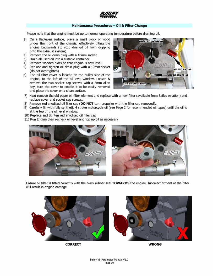
7) Next remove the old paper oil filter element and replace with a new filter (available from Bailey Aviation) and ___replace cover and socket cap screws. 8) Remove red anodised oil filler cap (DO NOT turn propeller with the filler cap removed). 9) Carefully fill with fully synthetic 4 stroke motorcycle oil (see Page 2 for recommended oil types) until the oil is ___at the top of the oil level window. 10) Replace and tighten red anodised oil filler cap 11) Run Engine then recheck oil level and top up oil as necessary
Maintenance Procedures – Oil & Filter Change Please note that the engine must be up to normal operating temperature before draining oil.
1) On a flat/even surface, place a small block of wood under the front of the chassis, effectively tilting the engine backwards (to stop drained oil from dripping onto the exhaust system)
2) Remove the oil drain plug with a 10mm socket 3) Drain all used oil into a suitable container 4) Remove wooden block so that engine is now level 5) Replace and tighten oil drain plug with a 10mm socket
(do not overtighten) 6) The oil filter cover is located on the pulley side of the
engine, to the left of the oil level window. Loosen & remove the two socket cap screws with a 5mm allen key, turn the cover to enable it to be easily removed and place the cover on a clean surface.
Ensure oil filter is fitted correctly with the black rubber seal TOWARDS the engine. Incorrect fitment of the filter will result in engine damage.
Bailey V5 Paramotor Manual V1.0 Page 11
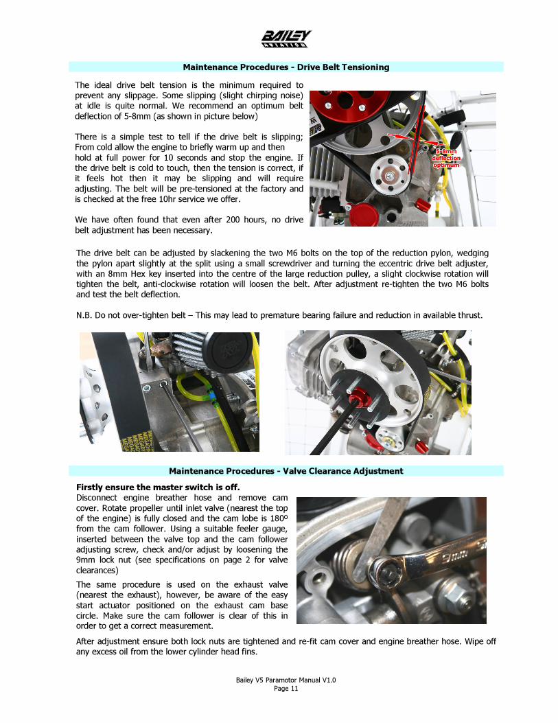
Maintenance Procedures - Drive Belt Tensioning
Maintenance Procedures - Valve Clearance Adjustment
The ideal drive belt tension is the minimum required to prevent any slippage. Some slipping (slight chirping noise) at idle is quite normal. We recommend an optimum belt deflection of 5-8mm (as shown in picture below) There is a simple test to tell if the drive belt is slipping; From cold allow the engine to briefly warm up and then hold at full power for 10 seconds and stop the engine. If the drive belt is cold to touch, then the tension is correct, if it feels hot then it may be slipping and will require adjusting. The belt will be pre-tensioned at the factory and is checked at the free 10hr service we offer. We have often found that even after 200 hours, no drive belt adjustment has been necessary.
Firstly ensure the master switch is off. Disconnect engine breather hose and remove cam cover. Rotate propeller until inlet valve (nearest the top of the engine) is fully closed and the cam lobe is 180º from the cam follower. Using a suitable feeler gauge, inserted between the valve top and the cam follower adjusting screw, check and/or adjust by loosening the 9mm lock nut (see specifications on page 2 for valve clearances)
The same procedure is used on the exhaust valve (nearest the exhaust), however, be aware of the easy start actuator positioned on the exhaust cam base circle. Make sure the cam follower is clear of this in order to get a correct measurement.
The drive belt can be adjusted by slackening the two M6 bolts on the top of the reduction pylon, wedging the pylon apart slightly at the split using a small screwdriver and turning the eccentric drive belt adjuster, with an 8mm Hex key inserted into the centre of the large reduction pulley, a slight clockwise rotation will tighten the belt, anti-clockwise rotation will loosen the belt. After adjustment re-tighten the two M6 bolts and test the belt deflection. N.B. Do not over-tighten belt – This may lead to premature bearing failure and reduction in available thrust.
After adjustment ensure both lock nuts are tightened and re-fit cam cover and engine breather hose. Wipe off any excess oil from the lower cylinder head fins.
Bailey V5 Paramotor Manual V1.0 Page 12
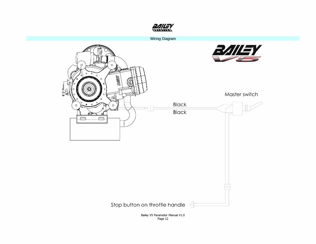
Wiring Diagram
Bailey V5 Paramotor Manual V1.0 Page 13
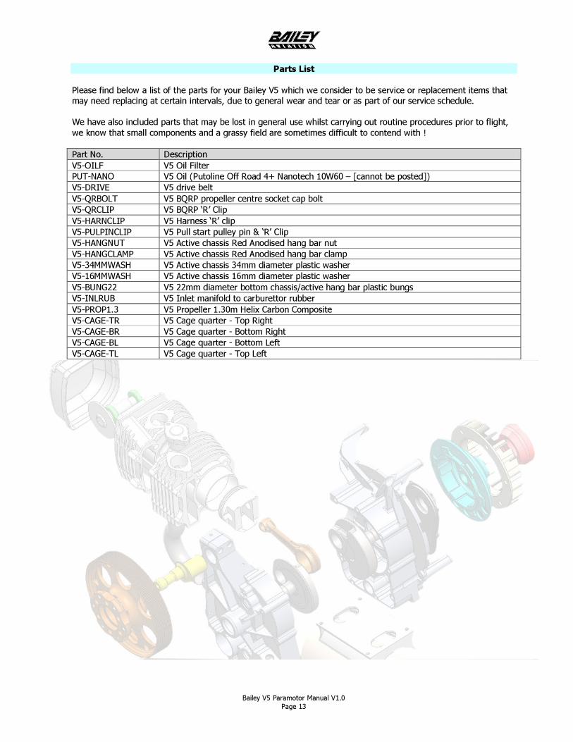
Parts List Please find below a list of the parts for your Bailey V5 which we consider to be service or replacement items that may need replacing at certain intervals, due to general wear and tear or as part of our service schedule. We have also included parts that may be lost in general use whilst carrying out routine procedures prior to flight, we know that small components and a grassy field are sometimes difficult to contend with ! Part No. Description V5-OILF V5 Oil Filter PUT-NANO V5 Oil (Putoline Off Road 4+ Nanotech 10W60 – [cannot be posted]) V5-DRIVE V5 drive belt V5-QRBOLT V5 BQRP propeller centre socket cap bolt V5-QRCLIP V5 BQRP ‘R’ Clip V5-HARNCLIP V5 Harness ‘R’ clip V5-PULPINCLIP V5 Pull start pulley pin & ‘R’ Clip V5-HANGNUT V5 Active chassis Red Anodised hang bar nut V5-HANGCLAMP V5 Active chassis Red Anodised hang bar clamp V5-34MMWASH V5 Active chassis 34mm diameter plastic washer V5-16MMWASH V5 Active chassis 16mm diameter plastic washer V5-BUNG22 V5 22mm diameter bottom chassis/active hang bar plastic bungs V5-INLRUB V5 Inlet manifold to carburettor rubber V5-PROP1.3 V5 Propeller 1.30m Helix Carbon Composite V5-CAGE-TR V5 Cage quarter - Top Right V5-CAGE-BR V5 Cage quarter - Bottom Right V5-CAGE-BL V5 Cage quarter - Bottom Left V5-CAGE-TL V5 Cage quarter - Top Left
Bailey V5 Paramotor Manual V1.0 Page 14
Warranty Bailey Aviation offers a 12-month limited parts and labour warranty on all engine components for the original purchaser. All warranty claims are return-to-base and can only be carried out by Bailey Aviation. Bailey Aviation cannot be held responsible for the payment of any delivery/freight charges, including customs duties or taxes. Warranty claims will not be accepted for the following situations:- Damage caused through immersion in water Damage caused through improper use Damage caused through failure to carry out proper PRE-FLIGHT CHECKS Damage caused through neglecting the SERVICE SCHEDULE Damage caused by physical dropping, falling or shocks to the paramotor or engine Damage caused through starting engine without a propeller properly fitted Damage caused through starting engine with incorrect propeller type Damage caused through incorrect adjustment of drive belt tension Damage caused through incorrect adjustment of valve clearances Damage caused through the use of incorrect fuel or oil type or grade Damage caused through lack of oil N.B. Any modification whatsoever to the engine design, without prior written approval from Bailey Aviation will render the manufacturers warranty null and void.
Disclaimer DANGER This engine, by its design is subject to sudden stoppage! Engine stoppage can result in forced landings. Such forced landings can lead to serious bodily injuries or death. Never fly an aircraft equipped with this engine at locations, airspeeds, altitudes or other circumstances from which a successful no-power landing cannot be made, after sudden engine stoppage. Aircraft equipped with this engine should only fly in DAYLIGHT VFR conditions. Paramotors are not certified or licensed aircraft and it is the responsibility of the owner/pilot to use the machine in accordance with the rules and regulations set out by the governing body in their designated country or territory. Bailey Aviation will not accept any claim for damage or death caused through the misuse of any product manufactured or used by them on their products. WARNING This is not a certified aircraft engine. It has not received any safety or durability testing and conforms to no aircraft standards. It is for use in experimental, uncertified aircraft and vehicles only in which an engine failure will not compromise safety. User assumes all risk of use and acknowledges by his use that he knows the engine is subject to sudden stoppage. This manual is for operational guidance on the Bailey V5 paramotor and engine only and is not a replacement for full professional training. Use of your paramotor is entirely at your own risk – Never fly if you are aware of any issues with your equipment, yourself or conditions. No part of this manual may be reproduced or distributed in any form or by any means without the prior written approval of Bailey Aviation
E. & O.E.
© Bailey Aviation 2012
Bailey V5 Paramotor Manual V1.0 Page 15
Notes Please use this section to make your own notes.