Embed Size (px)
Citation preview

From tool development to transient analysis
M. Tiberga, S. Lorenzi, R. de Oliveira
Final meeting, 4 July 2019
The MSFR is a circulating fuel reactor, => theprecursors are transported by the liquid fuel =>stronger coupling between neutronics and fluid-dynamics.
A helium bubbling system is foreseen for a moreefficient removal of the gaseous fission products,and as a possible option for the reactivity control.
The compressibility of the mixture may have animportant effect on dynamics behavior of theMSFR, expecially in fast, super-prompt-criticaltransients.
A multi-physics modellingapproach is required
Need to develop/extend and benchmark code systems
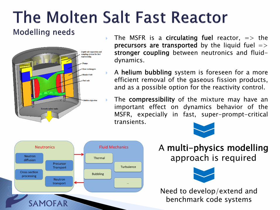
SN radiation transport code (PHANTOM-SN) coupled to RANS solver(DGFlows), both in house tools
Discontinuous Galerkin FEM for space discretization. Can handlestructured/unstructured meshes, and support local refinement
2nd order BDF schemes for time discretization.
DGFlows: solves low-Ma RANS equations, with pressure-correction.Can handle properties fully variable with temperature
PHANTOM-SN: solves the multi-group Boltzmann transport equationcoupled to delayed neutron precursors equations.
Extensive capabilities: principal andmultimodal calculations of criticality/time-eigenvalues; both regular and generalizedperturbation analysis
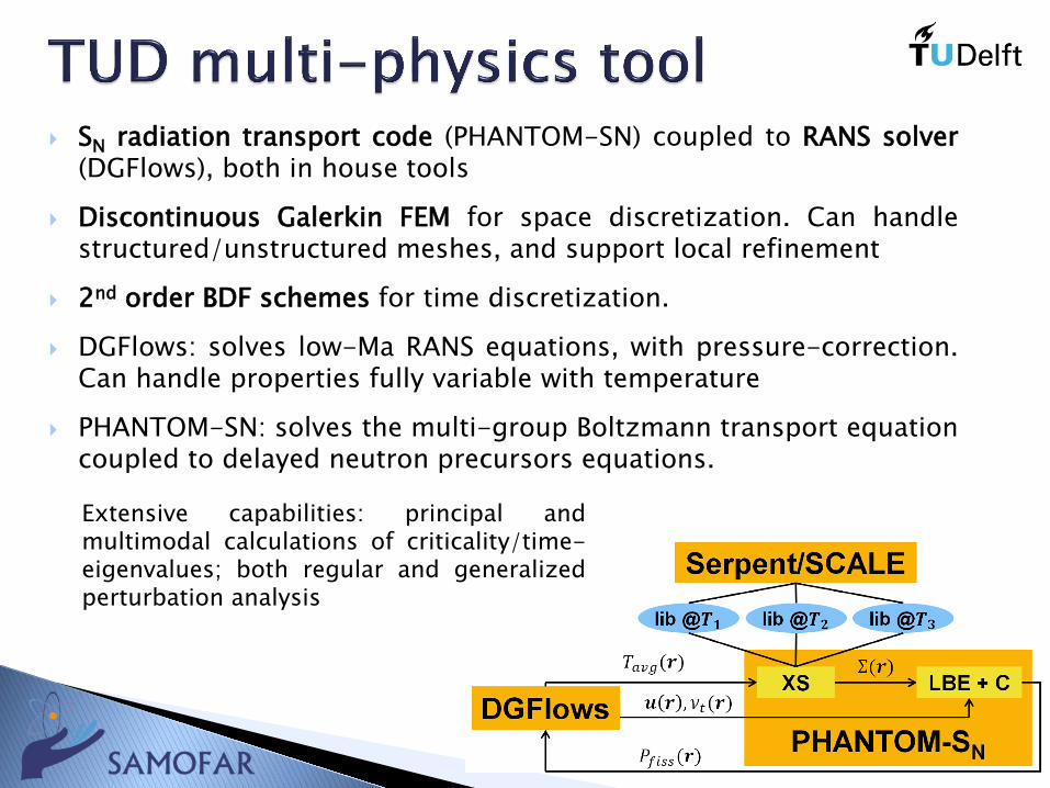
A multiphysics model has been developed, including:
Multi-group neutron diffusion equations;
Multi-group SP3 neutron transport equations;
A two-phase, compressible thermal-hydraulics model, based on a ‘’two-fluids’’ (or Euler-Euler) approach;
Transport equations for the moving precursors.
This model has been implemented into anOpenFOAM solver to study the accidentaltransients of the MSFR, the impact of thehelium bubbling system and the fuelcompressibility effects.
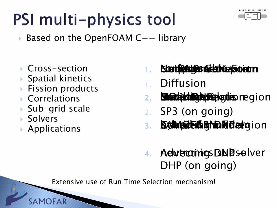
Cross-section Spatial kinetics Fission products Correlations Sub-grid scale Solvers Applications
1. No parametrization
2. MD interpolation
3. SAMOFAR model
Extensive use of Run Time Selection mechanism!
1. Diffusion
2. SP3 (on going)
1. No DNP
2. Static DNP
3. Advecting DNP
4. Advecting DNP + DHP (on going)
1. Uniform GeN-Foam
2. Heterogeneous
1. Homogeneous
2. Rod lattice
1. Neutron transport
2. Coupled single region
3. Coupled multi region
1. compressible
2. boussinesq
3. hybrid GeN-Foam
4. neutronics subsolver
Based on the OpenFOAM C++ library
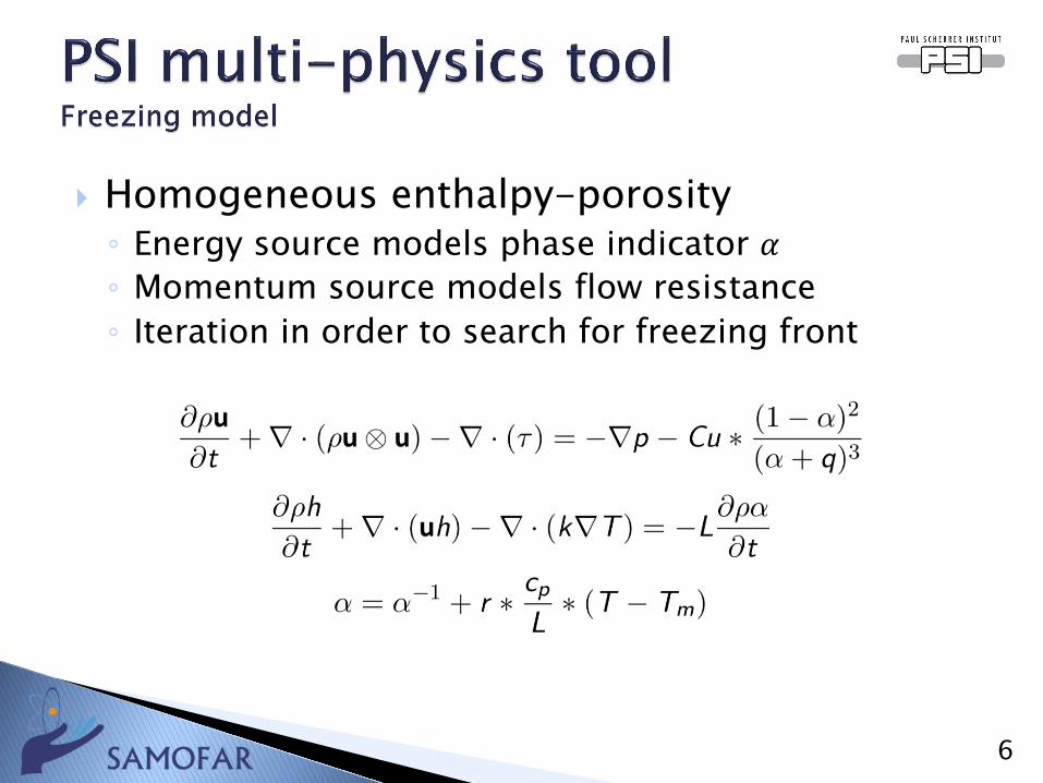
Homogeneous enthalpy-porosity◦ Energy source models phase indicator 𝛼𝛼◦ Momentum source models flow resistance◦ Iteration in order to search for freezing front
6
SIMMER code: review and modification of saltproperties (to match MSFR thermalconductivity)
Analytical models to simulate draining
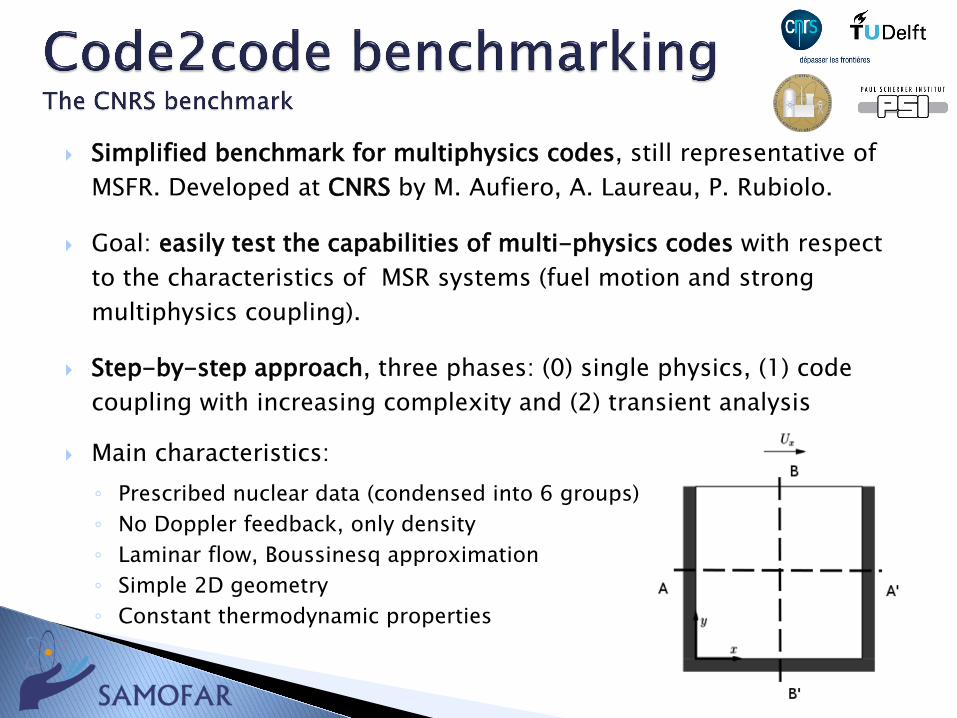
Simplified benchmark for multiphysics codes, still representative of MSFR. Developed at CNRS by M. Aufiero, A. Laureau, P. Rubiolo.
Goal: easily test the capabilities of multi-physics codes with respect to the characteristics of MSR systems (fuel motion and strong multiphysics coupling).
Step-by-step approach, three phases: (0) single physics, (1) code coupling with increasing complexity and (2) transient analysis
Main characteristics:◦ Prescribed nuclear data (condensed into 6 groups)◦ No Doppler feedback, only density◦ Laminar flow, Boussinesq approximation◦ Simple 2D geometry◦ Constant thermodynamic properties
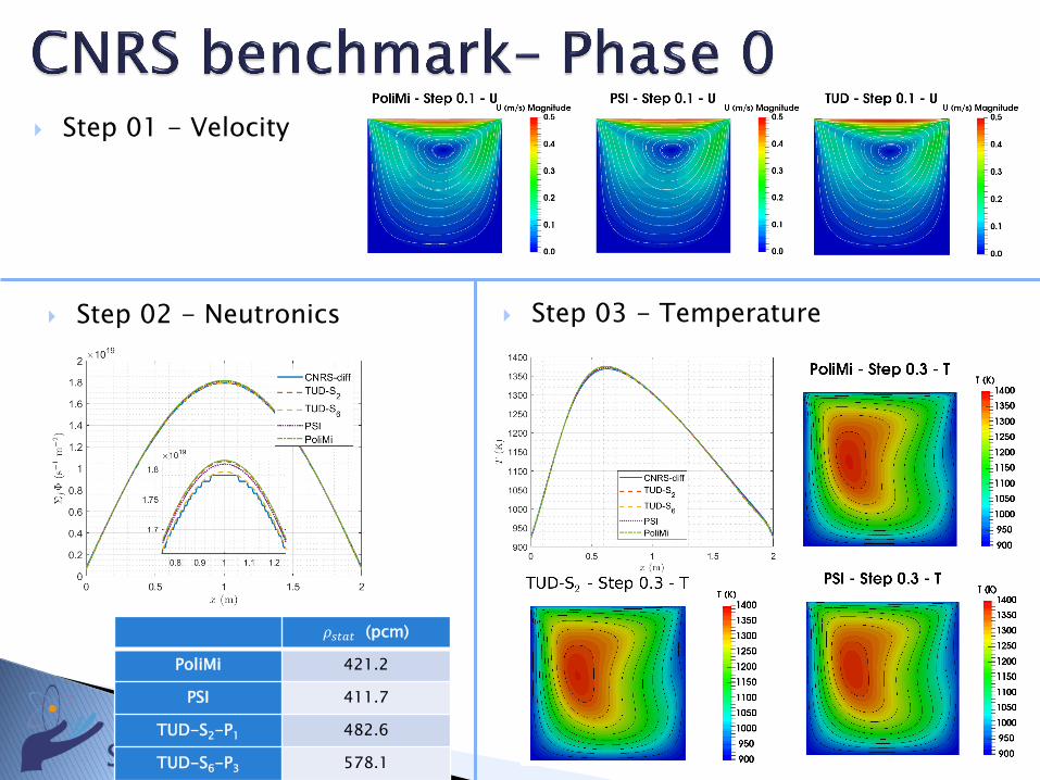
Step 01 - Velocity
Step 02 - Neutronics Step 03 - Temperature
𝜌𝜌𝑠𝑠𝑠𝑠𝑠𝑠𝑠𝑠 (pcm)
PoliMi 421.2
PSI 411.7
TUD-S2-P1 482.6
TUD-S6-P3 578.1
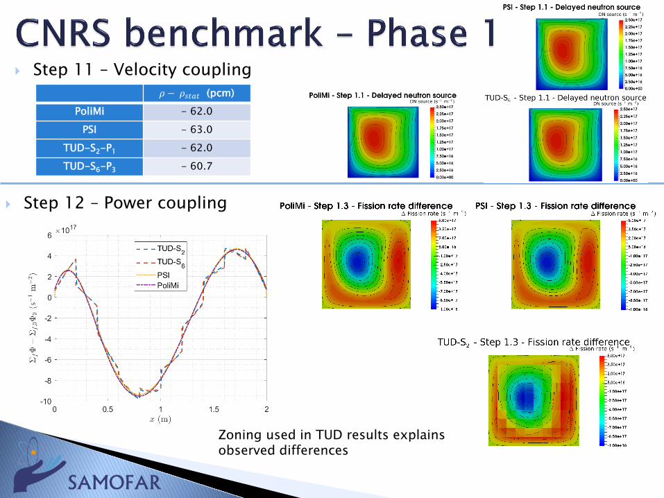
Step 11 – Velocity coupling
Step 12 – Power coupling
𝜌𝜌 − 𝜌𝜌𝑠𝑠𝑠𝑠𝑠𝑠𝑠𝑠 (pcm)PoliMi - 62.0
PSI - 63.0TUD-S2-P1 - 62.0TUD-S6-P3 - 60.7
Zoning used in TUD results explains observed differences
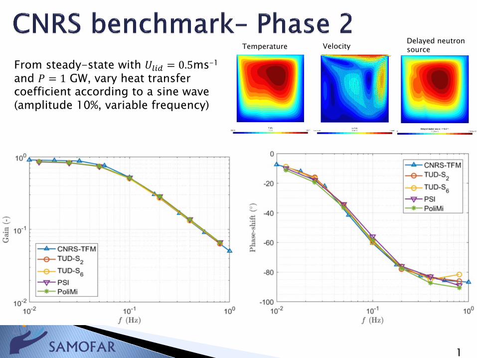
From steady-state with 𝑈𝑈𝑙𝑙𝑙𝑙𝑙𝑙 = 0.5ms-1
and 𝑃𝑃 = 1 GW, vary heat transfer coefficient according to a sine wave (amplitude 10%, variable frequency)
1
Temperature VelocityDelayed neutron source
Benchmark served its purpose Results of participants in good agreement.
Between a 0.1 and a few percent max Whenever there is a difference these can be
explained:◦ Meshing and order of approximation◦ Physics model used (diffusion vs transport, S2 vs S6)
Codes proved to be suitable to simulate MSFR behavior
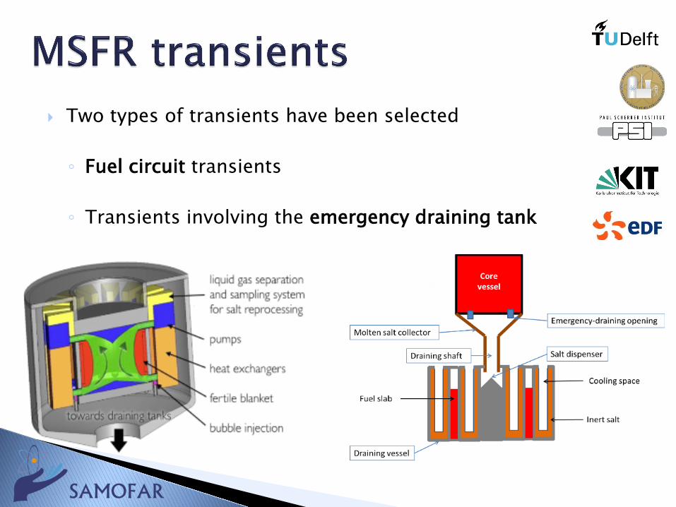
Two types of transients have been selected
◦ Fuel circuit transients
◦ Transients involving the emergency draining tank
ULOFF: The mass flow reduction is simulated with anexponential decay of the pump head with a timeconstant of 5 s
ULOHS – 1 (very conservative): step reduction of heattransfer coefficient (HTC) to zero
ULOHS – 2 (more realistic): vary HTC and secondaryaverage T in time, to mimic reduction of mass flowrate of intermediate circuit and ECS (to 20%). Again,exponential trends with 5s time constant
RAA: Step insertion of reactivity: 1.2$ (super-prompt critical) and 0.5$
OVC: Same approach as for ULOHS, but opposite:vary HTC and secondary average T to simulate fastincrease in extracted power
TLOP: Combination of ULOFF and ULOHS (quickreduction to zero of heat removal)
Draining of salt, after melting of freeze-valves.
Salt cooling in the draining tank
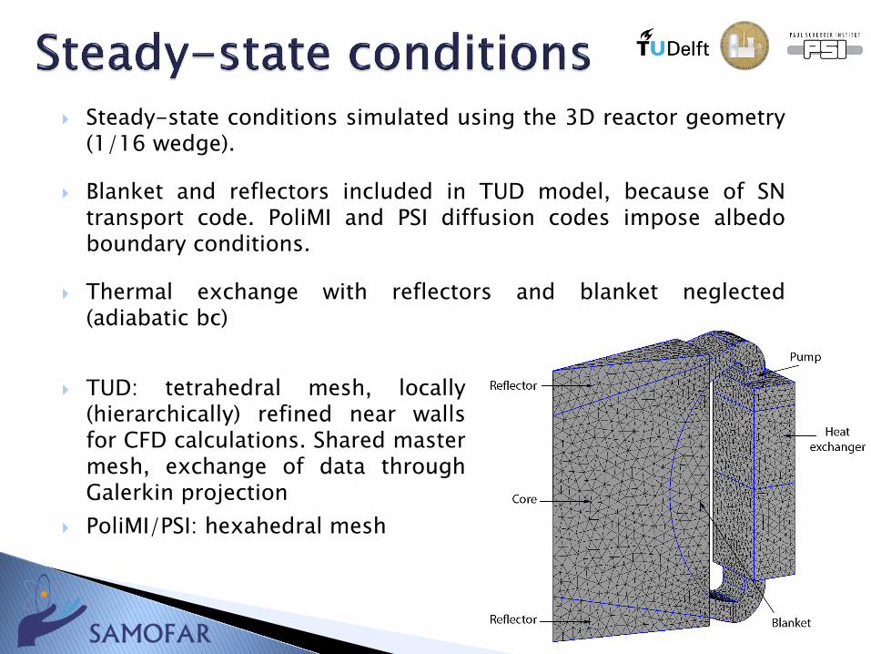
Steady-state conditions simulated using the 3D reactor geometry(1/16 wedge).
Blanket and reflectors included in TUD model, because of SNtransport code. PoliMI and PSI diffusion codes impose albedoboundary conditions.
Thermal exchange with reflectors and blanket neglected(adiabatic bc)
TUD: tetrahedral mesh, locally(hierarchically) refined near wallsfor CFD calculations. Shared mastermesh, exchange of data throughGalerkin projection
PoliMI/PSI: hexahedral mesh
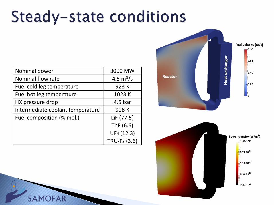
Nominal power 3000 MWNominal flow rate 4.5 m3/sFuel cold leg temperature 923 KFuel hot leg temperature 1023 KHX pressure drop 4.5 barIntermediate coolant temperature 908 KFuel composition (% mol.) LiF (77.5)
ThF (6.6)UF4 (12.3)
TRU-F3 (3.6)
19
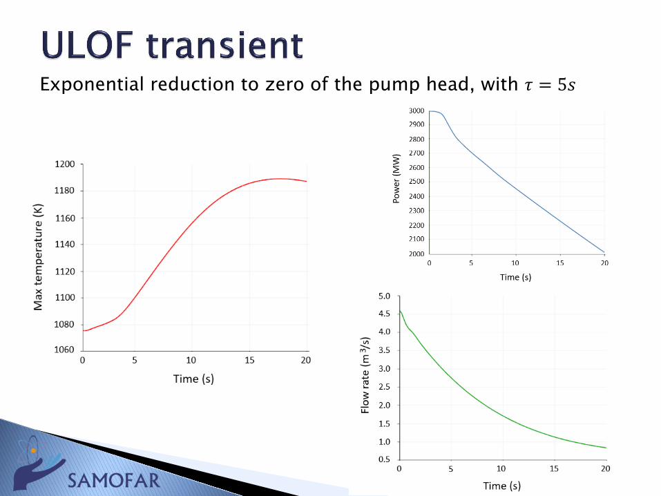
Exponential reduction to zero of the pump head, with 𝜏𝜏 = 5𝑠𝑠
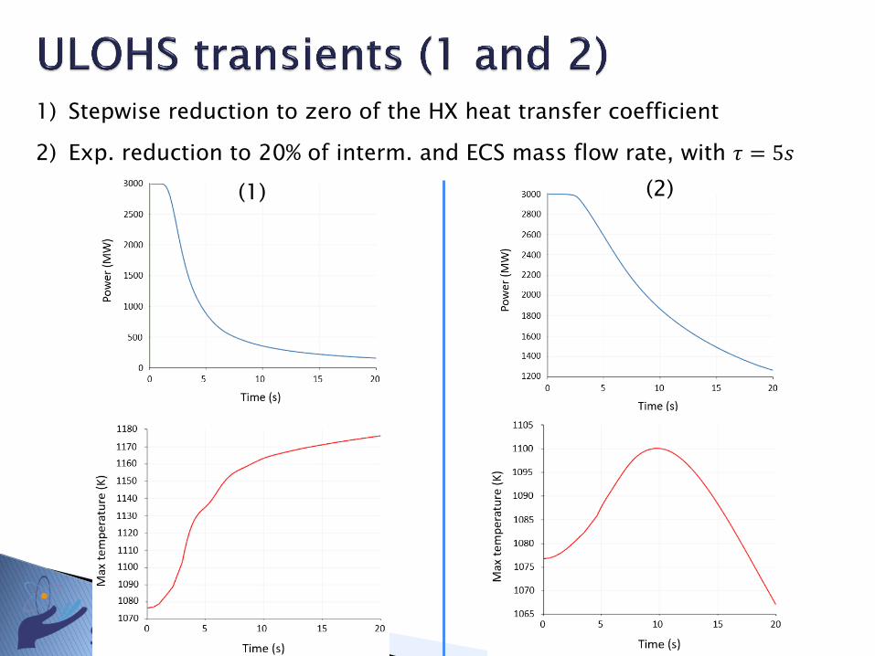
1) Stepwise reduction to zero of the HX heat transfer coefficient
2) Exp. reduction to 20% of interm. and ECS mass flow rate, with 𝜏𝜏 = 5𝑠𝑠
(1) (2)
REACTOR
HEAT EXCHANG
ER
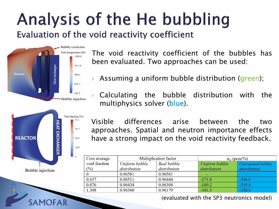
The void reactivity coefficient of the bubbles hasbeen evaluated. Two approaches can be used:
Assuming a uniform bubble distribution (green);
Calculating the bubble distribution with themultiphysics solver (blue).
Visible differences arise between the twoapproaches. Spatial and neutron importance effectshave a strong impact on the void reactivity feedback.
(evaluated with the SP3 neutronics model)
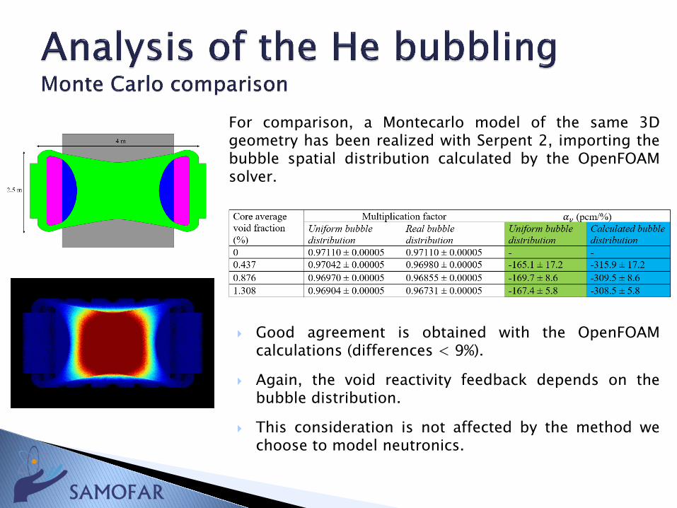
For comparison, a Montecarlo model of the same 3Dgeometry has been realized with Serpent 2, importing thebubble spatial distribution calculated by the OpenFOAMsolver.
Good agreement is obtained with the OpenFOAMcalculations (differences < 9%).
Again, the void reactivity feedback depends on thebubble distribution.
This consideration is not affected by the method wechoose to model neutronics.
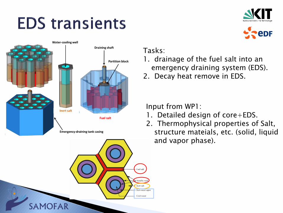
Tasks:1. drainage of the fuel salt into an
emergency draining system (EDS).2. Decay heat remove in EDS.
Input from WP1:1. Detailed design of core+EDS.2. Thermophysical properties of Salt,
structure mateials, etc. (solid, liquid and vapor phase).
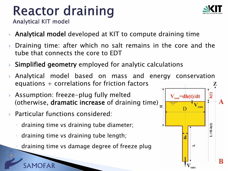
Analytical model developed at KIT to compute draining time Draining time: after which no salt remains in the core and the
tube that connects the core to EDT Simplified geometry employed for analytic calculations Analytical model based on mass and energy conservation
equations + correlations for friction factors Assumption: freeze-plug fully melted
(otherwise, dramatic increase of draining time) Particular functions considered:◦ draining time vs draining tube diameter;
◦ draining time vs draining tube length;
◦ draining time vs damage degree of freeze plug
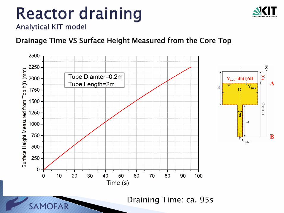
Draining Time: ca. 95s
Drainage Time VS Surface Height Measured from the Core Top
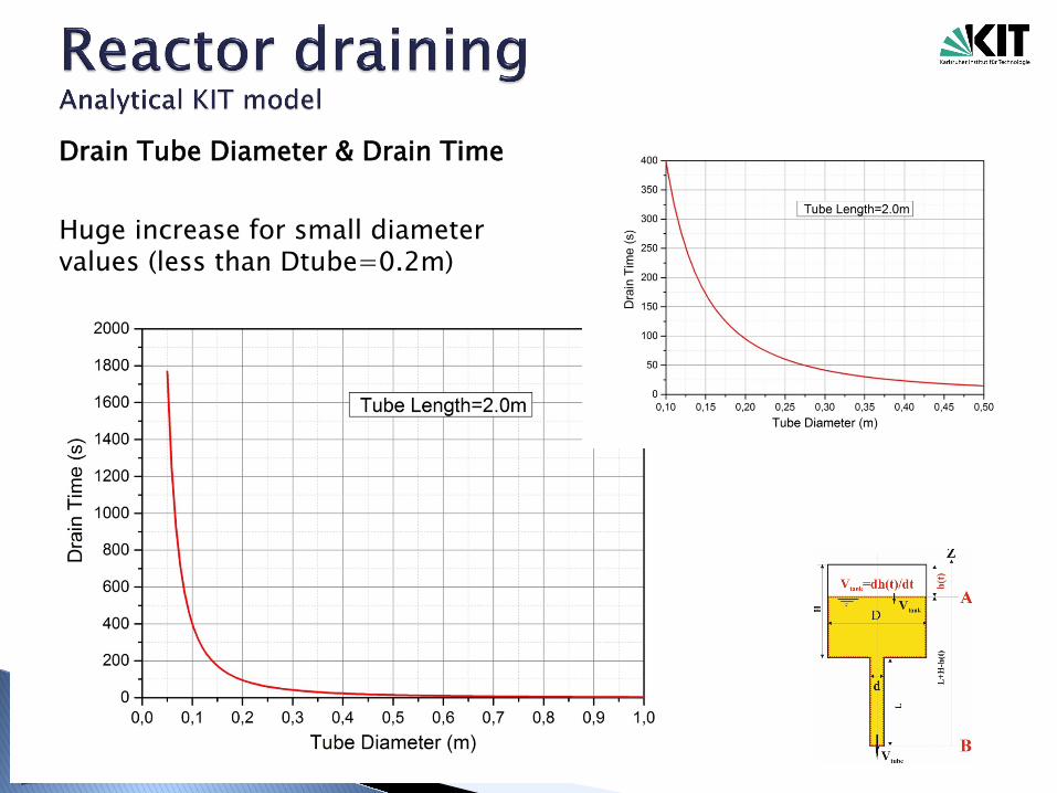
Drain Tube Diameter & Drain Time
Huge increase for small diameter values (less than Dtube=0.2m)
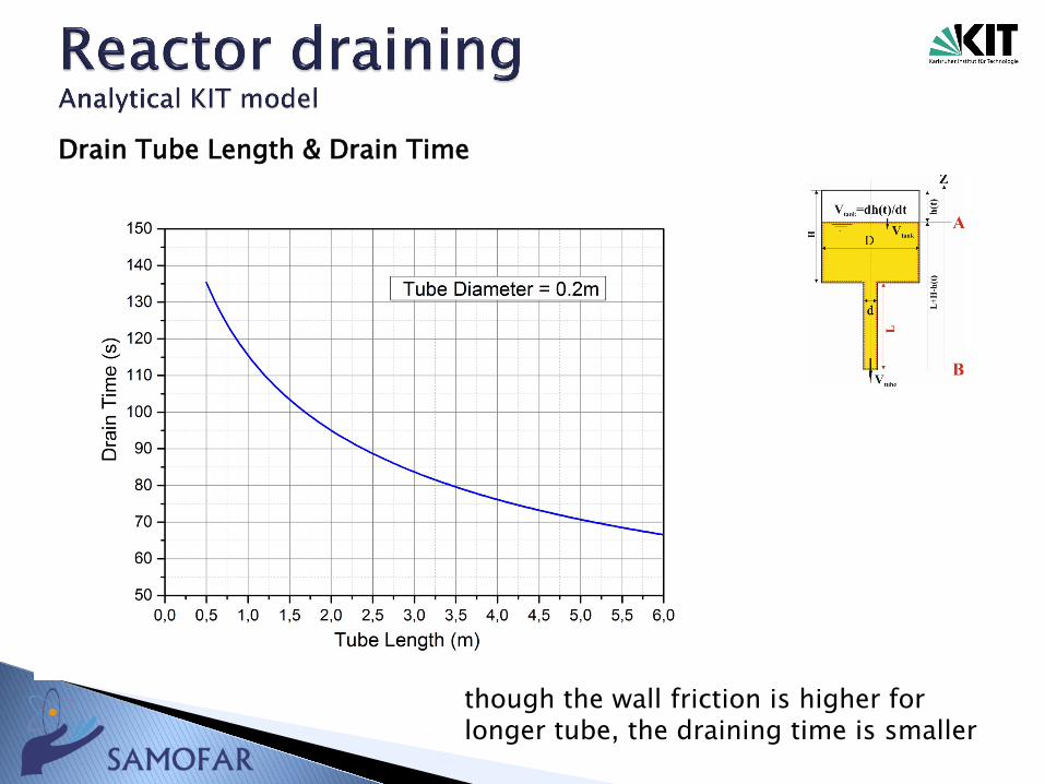
Drain Tube Length & Drain Time
though the wall friction is higher for longer tube, the draining time is smaller
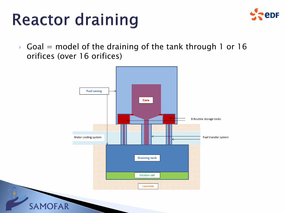
Goal = model of the draining of the tank through 1 or 16 orifices (over 16 orifices)
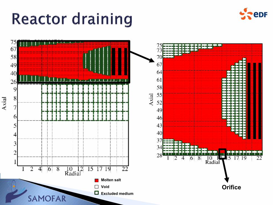
Molten salt
Void
Excluded mediumOrifice
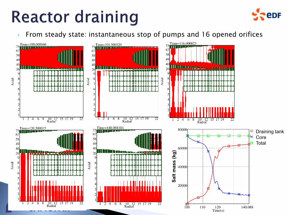
From steady state: instantaneous stop of pumps and 16 opened orifices
Draining tankCoreTotal
Salt
mas
s (k
g)
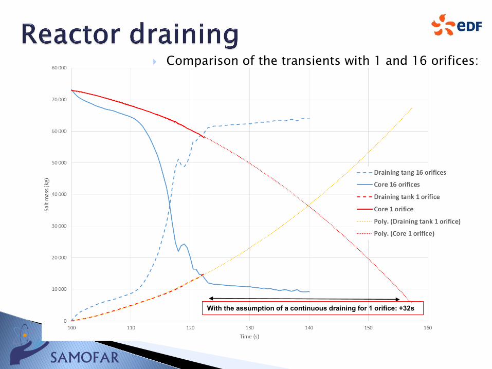
With the assumption of a continuous draining for 1 orifice: +32s
Comparison of the transients with 1 and 16 orifices:
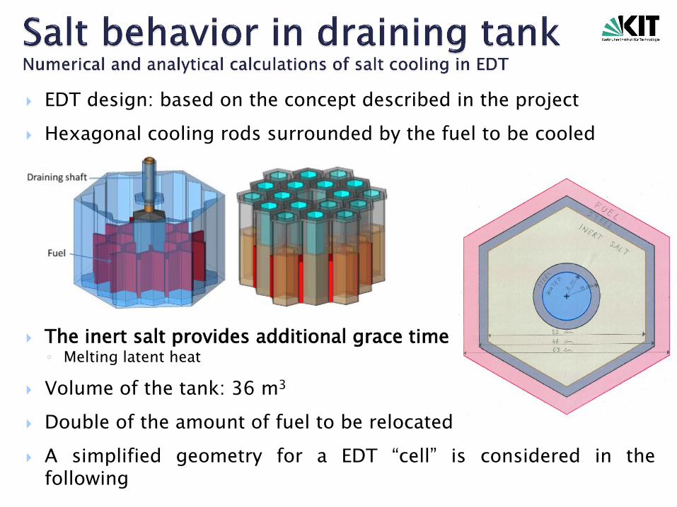
EDT design: based on the concept described in the project Hexagonal cooling rods surrounded by the fuel to be cooled
The inert salt provides additional grace time◦ Melting latent heat
Volume of the tank: 36 m3
Double of the amount of fuel to be relocated A simplified geometry for a EDT “cell” is considered in the
following
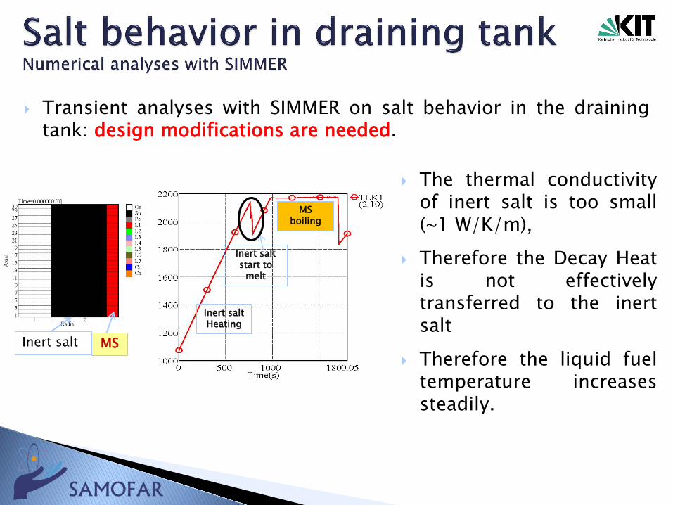
Transient analyses with SIMMER on salt behavior in the drainingtank: design modifications are needed.
The thermal conductivityof inert salt is too small(~1 W/K/m),
Therefore the Decay Heatis not effectivelytransferred to the inertsalt
Therefore the liquid fueltemperature increasessteadily.
Inert salt MS
Inert salt start to
melt
Inert salt Heating
MSboiling
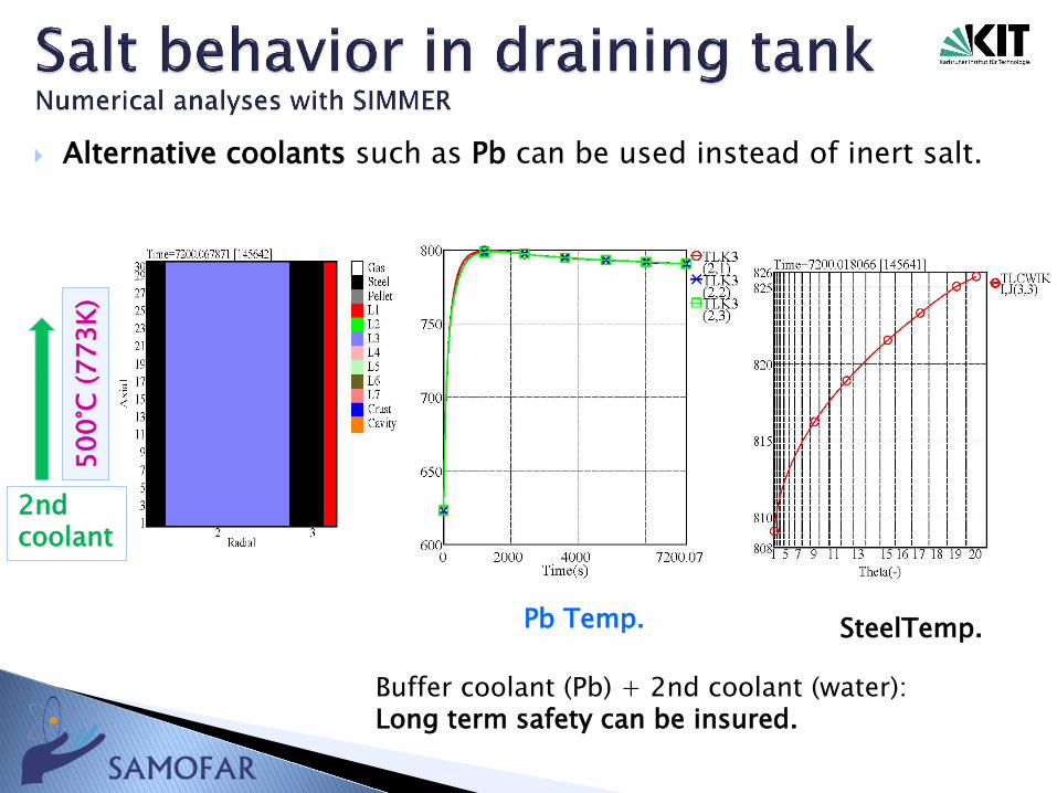
Alternative coolants such as Pb can be used instead of inert salt.
Pb Temp. SteelTemp.
500°
C (7
73K)
2nd coolant
Buffer coolant (Pb) + 2nd coolant (water): Long term safety can be insured.
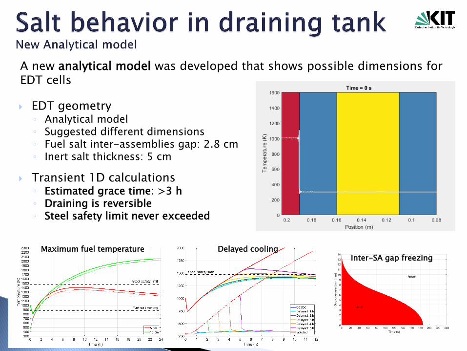
EDT geometry◦ Analytical model◦ Suggested different dimensions◦ Fuel salt inter-assemblies gap: 2.8 cm◦ Inert salt thickness: 5 cm
Transient 1D calculations◦ Estimated grace time: >3 h◦ Draining is reversible◦ Steel safety limit never exceeded
Maximum fuel temperature Delayed coolingInter-SA gap freezing
A new analytical model was developed that shows possible dimensions for EDT cells
New codes have been developed or extended
Code-to-code benchmarking proved the tools areable to reproduce accurately the characteristics ofthe MSFR
Steady state and transient conditions have beensimulated
Both analytical models and numerical tools havebeen exploited to simulate reactor draining andsalt cooling in the EDS

THANK YOUFOR YOUR KIND ATTENTION!