Embed Size (px)
Citation preview
Distributed Worldwide:Michael Stevens & Partners LtdInv icta Works Ell iott Road Bromley Kent BR2 9NT UKTel: +44 (0)20 8460 7299 Fax: +44 (0)20 8460 0499E-ma i l : sales@m ichael -stevens.comWeb:http:/ /www.chromatec.com
AM-32/8SIn-picture audio meter
From the range of in-picture audio meters by Chromatec
User instructions
Chromatec AM-32/8S
2005-6 Michael Stevens & Partners Ltd
Michael Stevens & Partners Ltd. has made every effort to ensure the accuracy of informationcontained within this document which is nevertheless supplied for information purposes only anddoes not constitute any form of warranty or guarantee.
All trademarks acknowledged.
The information in this document is subject to change without notice.
Michael Stevens & Partners LtdInvicta WorksElliott RoadBromleyKentBR2 9NTTel: +44 (0)20 8460 7299Fax: +44 (0)20 8460 0499Email: [email protected] site: www.michael-stevens.com www.chromatec.com
Chromatec AM-32/8S
2009 Michael Stevens & Partners Ltd
CCoonntteennttssINTRODUCTION 1
Main features 1Additional features 2
INPUT CARDS 3The Dolby® Digital decoder 3
THE ON-SCREEN DISPLAY 4Layout presets 4Bargraph meters 6Alarm indicators 6
OPERATION 7OPERATING MODES 7
Normal mode 7Menu mode 8
CONTROL BUTTON SUMMARY 9MENU COMMANDS 10
Menu page 1 User configuration, bargraph layout and scale select 10Menu Page 2 Bar ranges, colours, labels and scale reference 12Menu Page 3 Phase bar enable and assignment 13Menu Page 4 Phase bar more, audio monitor, AES status 14Menu Page 5 Alarm configuration 16Menu Page 6 Alarms more, timecode, data ports 17Menu Page 7 System status and configuration 18Menu Page 8 Contact Information 19
INSTALLATION 20SELECTING THE MAINS VOLTAGE 20HEALTH AND SAFETY CONSIDERATIONS 21
Disposal 21Supplied accessories 21
INPUT CARD CONFIGURATIONS 22CONNECTOR I/O 23
Single input card connector pinout 24Dual input card connector pinout 25
SURROUND SOUND CHANNEL ASSIGNMENTS 26CHANGING DOLBY DIGITAL INPUT TERMINATION VALUES 27
Chromatec AM-32/8S
2009 Michael Stevens & Partners Ltd
PROBLEM SOLVING 29Sample problems and their solutions 29
SPECIFICATION 30
Chromatec AM-32/8S Introduction
2009 Michael Stevens & Partners Ltd 1 Version 1.6
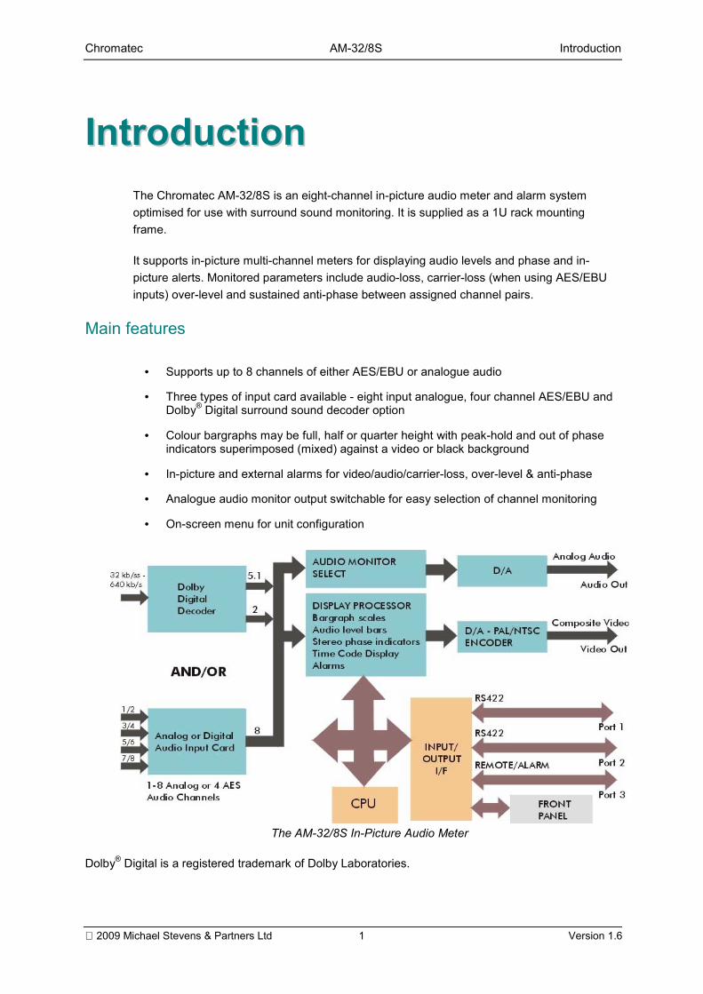
IInnttrroodduuccttiioonnThe Chromatec AM-32/8S is an eight-channel in-picture audio meter and alarm systemoptimised for use with surround sound monitoring. It is supplied as a 1U rack mountingframe.
It supports in-picture multi-channel meters for displaying audio levels and phase and in-picture alerts. Monitored parameters include audio-loss, carrier-loss (when using AES/EBUinputs) over-level and sustained anti-phase between assigned channel pairs.
Main features
• Supports up to 8 channels of either AES/EBU or analogue audio
• Three types of input card available - eight input analogue, four channel AES/EBU andDolby® Digital surround sound decoder option
• Colour bargraphs may be full, half or quarter height with peak-hold and out of phaseindicators superimposed (mixed) against a video or black background
• In-picture and external alarms for video/audio/carrier-loss, over-level & anti-phase
• Analogue audio monitor output switchable for easy selection of channel monitoring
• On-screen menu for unit configuration
The AM-32/8S In-Picture Audio Meter
Dolby® Digital is a registered trademark of Dolby Laboratories.
Chromatec AM-32/8S Introduction
2009 Michael Stevens & Partners Ltd 2 Version 1.6
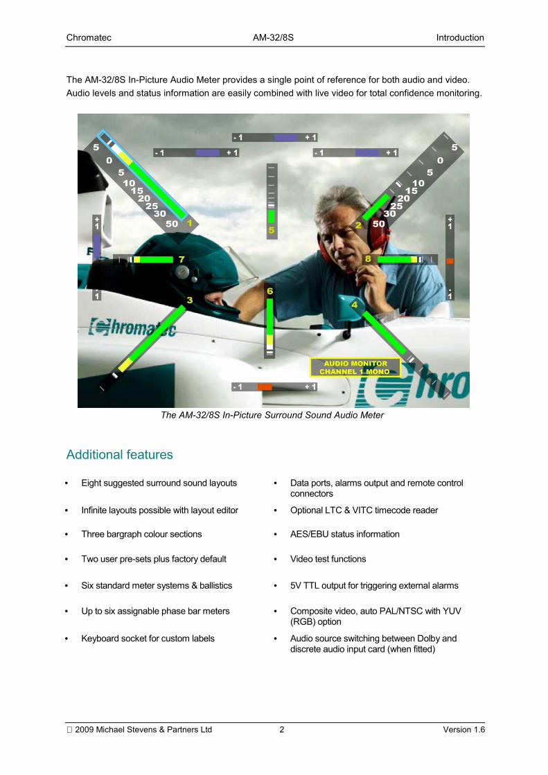
The AM-32/8S In-Picture Audio Meter provides a single point of reference for both audio and video.Audio levels and status information are easily combined with live video for total confidence monitoring.
The AM-32/8S In-Picture Surround Sound Audio Meter
Additional features
• Eight suggested surround sound layouts • Data ports, alarms output and remote controlconnectors
• Infinite layouts possible with layout editor • Optional LTC & VITC timecode reader
• Three bargraph colour sections • AES/EBU status information
• Two user pre-sets plus factory default • Video test functions
• Six standard meter systems & ballistics • 5V TTL output for triggering external alarms
• Up to six assignable phase bar meters • Composite video, auto PAL/NTSC with YUV(RGB) option
• Keyboard socket for custom labels • Audio source switching between Dolby anddiscrete audio input card (when fitted)
Chromatec AM-32/8S Introduction
2009 Michael Stevens & Partners Ltd 3 Version 1.6
Input cardsThere are three types of input card available for the AM-32/8S, an eight input analogue audiocard, a four channel AES/EBU digital audio card or a Dolby® Digital surround sound decoder.Normally only one input card is fitted, however if a Dolby® Digital card is specified then anadditional discrete analogue or AES/EBU input card may be fitted.
In a Dolby® Digital /discrete card configuration, each input card will function in exactly thesame way in terms of on-screen display, alarms and audio monitoring. However, only onecard can be selected at any one time for on-screen monitoring and alarms. A momentary on-screen message will appear confirming the card selection.
The dual input card facility is provided to allow comparative monitoring between discrete andDolby Digital coded sources. For example, DVD authoring, transmission or post areas wherediscrete channels are being Dolby Digital coded for domestic distribution.
Please refer to the Installation chapter for more details of fitted input card options.
The Dolby® Digital decoder
The Dolby® Digital decoder option is based on technology designed by Dolby Laboratorieswhich is used as the sound format for digital television (DTV), digital versatile discs (DVDs),high definition television (HDTV), and digital cable/satellite transmissions.
A Dolby® Digital multichannel audio coder obtains high efficiency by coding a multiplicity ofchannels as a single entity instead of a number of single channel coders.
The AC-3 algorithms used by Dolby Digital technology are standardised on the SMPTE-recommended 5.1 channel arrangement of five full bandwidth channels, known as a 3/2configuration. The five channels are Left, Centre, Right, Left-Surround, and Right-Surround.The 0.1 channel is an additional limited bandwidth low-frequency Subwoofer channel.
When all eight channels are being displayed by the Chromatec Dolby® Digital option,channels 7 and 8 display a stereo Dolby® Surround Downmix of the whole image as a five-channel 3/2 configuration encoded as a stereo compatible two-channel signal. If the input isa two-channel linear PCM signal, it is displayed on channels 1 and 2.
The Dolby® Digital decoder manufactured under license from Dolby Laboratories. Dolbyand the double-D symbol are trademarks of Dolby Laboratories. Confidential UnpublishedWorks. ©1992-1997 Dolby Laboratories, Inc; all rights reserved.
Chromatec AM-32/8S Introduction
2009 Michael Stevens & Partners Ltd 4 Version 1.6
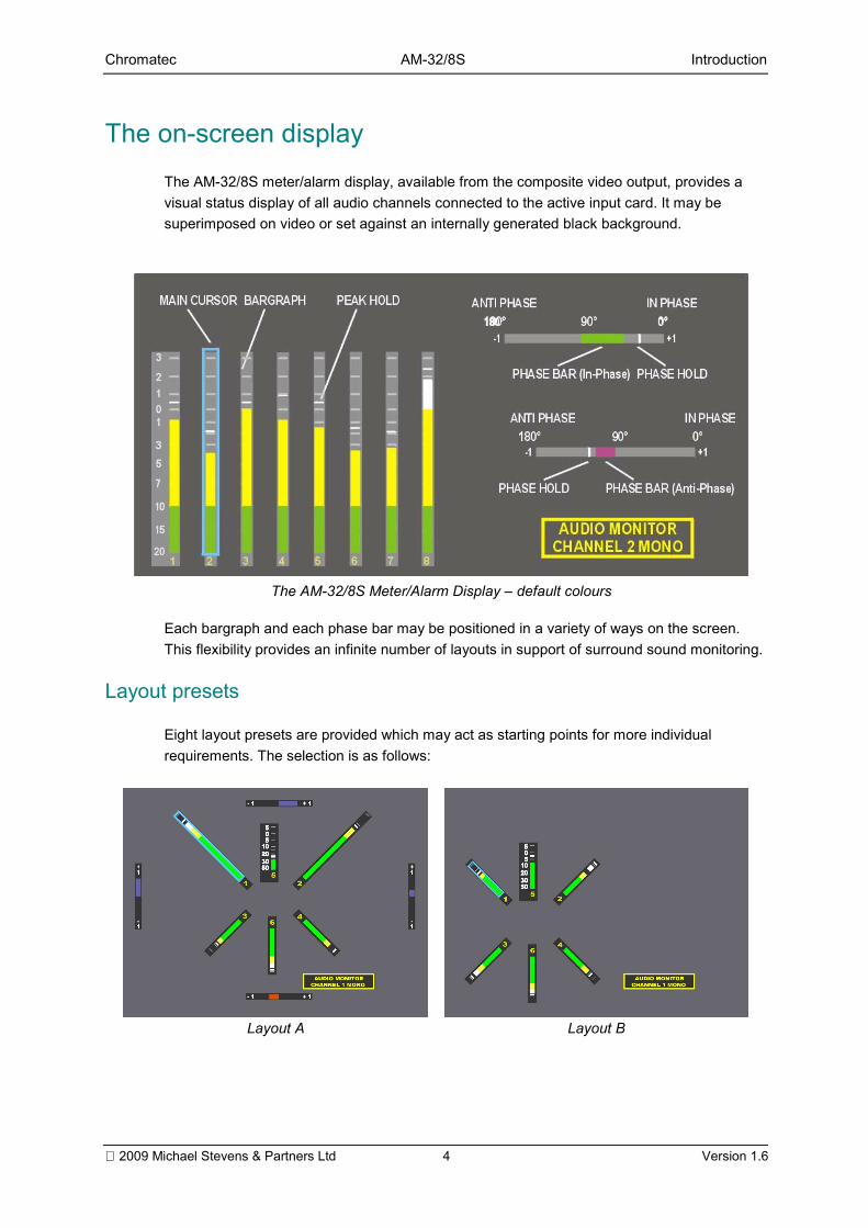
The on-screen displayThe AM-32/8S meter/alarm display, available from the composite video output, provides avisual status display of all audio channels connected to the active input card. It may besuperimposed on video or set against an internally generated black background.
The AM-32/8S Meter/Alarm Display default colours
Each bargraph and each phase bar may be positioned in a variety of ways on the screen.This flexibility provides an infinite number of layouts in support of surround sound monitoring.
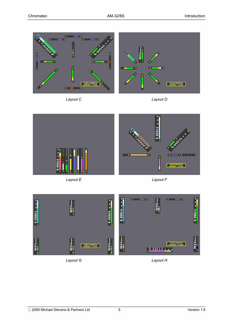
Layout presets
Eight layout presets are provided which may act as starting points for more individualrequirements. The selection is as follows:
Layout A Layout B
Chromatec AM-32/8S Introduction
2009 Michael Stevens & Partners Ltd 5 Version 1.6
Layout C Layout D
Layout E Layout F
Layout G Layout H
Chromatec AM-32/8S Introduction
2009 Michael Stevens & Partners Ltd 6 Version 1.6
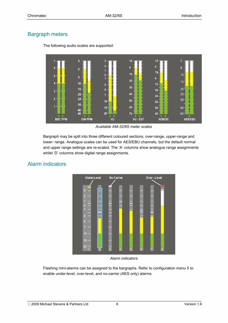
Bargraph meters
The following audio scales are supported:
Available AM-32/8S meter scales
Bargraph may be split into three different coloured sections, over-range, upper-range andlower- range. Analogue scales can be used for AES/EBU channels, but the default normaland upper range settings are re-scaled. The A columns show analogue range assignmentswhilst D columns show digital range assignments.
Alarm indicators
Alarm indicators
Flashing mini-alarms can be assigned to the bargraphs. Refer to configuration menu 5 toenable under-level, over-level, and no-carrier (AES only) alarms.
Chromatec AM-32/8S Operation
2009 Michael Stevens & Partners Ltd 7 Version 1.6
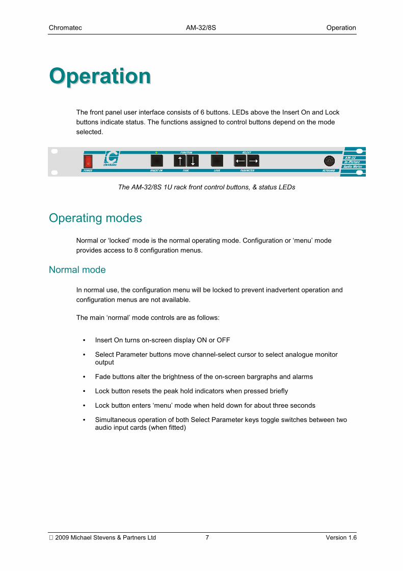
OOppeerraattiioonnThe front panel user interface consists of 6 buttons. LEDs above the Insert On and Lockbuttons indicate status. The functions assigned to control buttons depend on the modeselected.
The AM-32/8S 1U rack front control buttons, & status LEDs
Operating modesNormal or locked mode is the normal operating mode. Configuration or menu modeprovides access to 8 configuration menus.
Normal mode
In normal use, the configuration menu will be locked to prevent inadvertent operation andconfiguration menus are not available.
The main normal mode controls are as follows:
• Insert On turns on-screen display ON or OFF
• Select Parameter buttons move channel-select cursor to select analogue monitoroutput
• Fade buttons alter the brightness of the on-screen bargraphs and alarms
• Lock button resets the peak hold indicators when pressed briefly
• Lock button enters menu mode when held down for about three seconds
• Simultaneous operation of both Select Parameter keys toggle switches between twoaudio input cards (when fitted)
Chromatec AM-32/8S Operation
2009 Michael Stevens & Partners Ltd 8 Version 1.6
Menu mode
To enter menu mode from normal mode (with the red Lock LED off) hold the Lock buttondown for about 3 seconds. The configuration or menu mode will be entered, on-screenmenus will appear and the red Lock LED will illuminate. If the Lock button is held downagain, any changed settings will be saved and the AM-32/8S will return to normal metermode.
The menu mode will return to the last menu item visited provided the unit has not been resetor switched off since a configuration menu was last accessed.
The main menu mode controls are as follows:
• Function scrolls menu cursor up and down to select function
• Select Parameter selects settings to apply to chosen parameter
• Insert On + Select Parameter selects extended settings in right hand column
• Lock button leaves menu mode and saves settings when held down for about threeseconds
• Simultaneous operation of both Fade/Function keys toggles a "menu hide" facility. Thisassists in the editing of certain on-screen display functions. The red Lock and greenInsert LEDs, together with a red square in the screen centre, will flash to indicate whenmenu hide is active.
The factory fitted options of analogue, digital or Dolby® Digital audio input card and timecodecards are automatically detected and the configuration menus are updated accordingly.
Chromatec AM-32/8S Operation
2009 Michael Stevens & Partners Ltd 9 Version 1.6
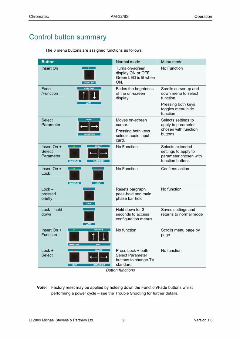
Control button summaryThe 6 menu buttons are assigned functions as follows:
Button Normal mode Menu modeInsert On Turns on-screen
display ON or OFF.Green LED is lit whenON.
No Function
Fade/Function
Fades the brightnessof the on-screendisplay
Scrolls cursor up anddown menu to selectfunction.Pressing both keystoggles menu hidefunction
SelectParameter
Moves on-screencursor.Pressing both keysselects audio inputcard.
Selects settings toapply to parameterchosen with functionbuttons
Insert On +SelectParameter
No Function Selects extendedsettings to apply toparameter chosen withfunction buttons
Insert On +Lock
No Function Confirms action
Lock pressedbriefly
Resets bargraphpeak-hold and mainphase bar hold
No function
Lock helddown
Hold down for 3seconds to accessconfiguration menus
Saves settings andreturns to normal mode
Insert On +Function
No function Scrolls menu page bypage
Lock +Select
Press Lock + bothSelect Parameterbuttons to change TVstandard
No function
Button functions
Note: Factory reset may be applied by holding down the Function/Fade buttons whilstperforming a power cycle see the Trouble Shooting for further details.
Chromatec AM-32/8S Operation
2009 Michael Stevens & Partners Ltd 10 Version 1.6
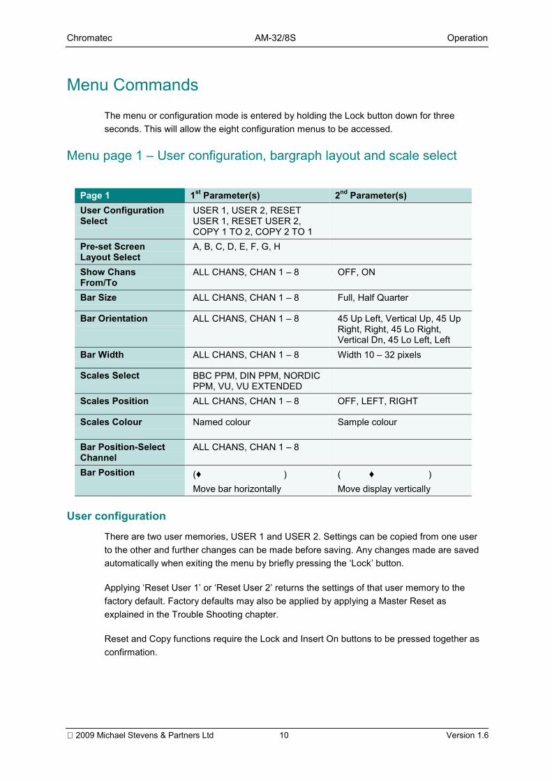
Menu CommandsThe menu or configuration mode is entered by holding the Lock button down for threeseconds. This will allow the eight configuration menus to be accessed.
Menu page 1 User configuration, bargraph layout and scale select
Page 1 1st Parameter(s) 2nd Parameter(s)User ConfigurationSelect
USER 1, USER 2, RESETUSER 1, RESET USER 2,COPY 1 TO 2, COPY 2 TO 1
Pre-set ScreenLayout Select
A, B, C, D, E, F, G, H
Show ChansFrom/To
ALL CHANS, CHAN 1 8 OFF, ON
Bar Size ALL CHANS, CHAN 1 8 Full, Half Quarter
Bar Orientation ALL CHANS, CHAN 1 8 45 Up Left, Vertical Up, 45 UpRight, Right, 45 Lo Right,Vertical Dn, 45 Lo Left, Left
Bar Width ALL CHANS, CHAN 1 8 Width 10 32 pixels
Scales Select BBC PPM, DIN PPM, NORDICPPM, VU, VU EXTENDED
Scales Position ALL CHANS, CHAN 1 8 OFF, LEFT, RIGHT
Scales Colour Named colour Sample colour
Bar Position-SelectChannel
ALL CHANS, CHAN 1 8
Bar Position (♦ )Move bar horizontally
( ♦ )Move display vertically
User configuration
There are two user memories, USER 1 and USER 2. Settings can be copied from one userto the other and further changes can be made before saving. Any changes made are savedautomatically when exiting the menu by briefly pressing the Lock button.
Applying Reset User 1 or Reset User 2 returns the settings of that user memory to thefactory default. Factory defaults may also be applied by applying a Master Reset asexplained in the Trouble Shooting chapter.
Reset and Copy functions require the Lock and Insert On buttons to be pressed together asconfirmation.
Chromatec AM-32/8S Operation
2009 Michael Stevens & Partners Ltd 11 Version 1.6
Bar layouts
Eight built-in layouts are provided as suggested surround-sound monitoring displays (refer topages 4 and 5). These layouts can easily be edited or entirely different layouts created.Individual bargraphs may be shown or hidden from the display at any time.
Bar size
The bargraphs may be displayed in Quarter, Half, Normal (full height) mode.
Bar orientation, width and position
Each bargraph may be individually adjusted for orientation, width and position. Width isdisplayed in pixels. Orientation provides eight positions in 45-degree rotational steps. Thescale numbering always increases from top to bottom.
Bargraph scales
Standard scales and their corresponding ballistics may be selected. These may bepositioned to the left, right or both sides of the relevant bargraphs. The bargraph may be splitinto three different coloured sections, over-range, upper-range and lower- range.
If only one or two colours for each bargraph are preferred, then the upper and lower-rangepoints may be set to an equal level or changed to the same colour.
The AES/EBU scale is designed for use with digital audio. Analogue scales can be used forAES/EBU channels, but the default normal and upper range settings are re-scaled.
The 0dB scale reference may be set from 0dB to 30dB when any scale is used for digitalaudio.
Chromatec AM-32/8S Operation
2009 Michael Stevens & Partners Ltd 12 Version 1.6
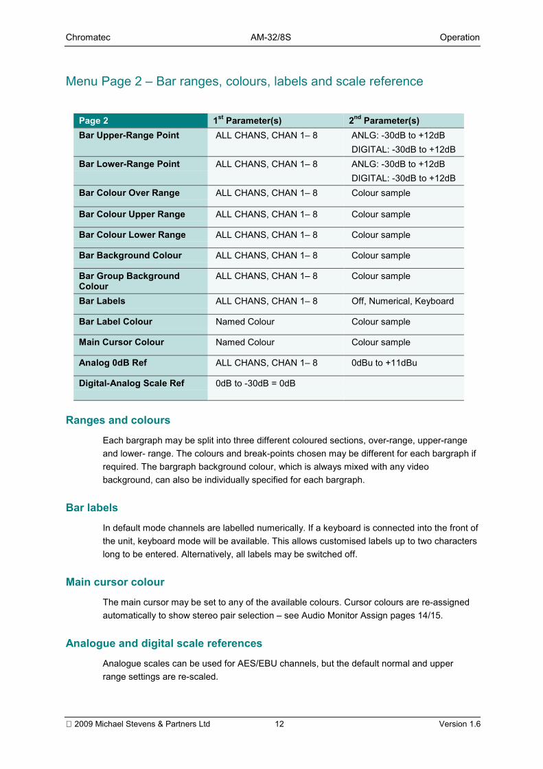
Menu Page 2 Bar ranges, colours, labels and scale reference
Page 2 1st Parameter(s) 2nd Parameter(s)Bar Upper-Range Point ALL CHANS, CHAN 1 8 ANLG: -30dB to +12dB
DIGITAL: -30dB to +12dBBar Lower-Range Point ALL CHANS, CHAN 1 8 ANLG: -30dB to +12dB
DIGITAL: -30dB to +12dBBar Colour Over Range ALL CHANS, CHAN 1 8 Colour sample
Bar Colour Upper Range ALL CHANS, CHAN 1 8 Colour sample
Bar Colour Lower Range ALL CHANS, CHAN 1 8 Colour sample
Bar Background Colour ALL CHANS, CHAN 1 8 Colour sample
Bar Group BackgroundColour
ALL CHANS, CHAN 1 8 Colour sample
Bar Labels ALL CHANS, CHAN 1 8 Off, Numerical, Keyboard
Bar Label Colour Named Colour Colour sample
Main Cursor Colour Named Colour Colour sample
Analog 0dB Ref ALL CHANS, CHAN 1 8 0dBu to +11dBu
Digital-Analog Scale Ref 0dB to -30dB = 0dB
Ranges and colours
Each bargraph may be split into three different coloured sections, over-range, upper-rangeand lower- range. The colours and break-points chosen may be different for each bargraph ifrequired. The bargraph background colour, which is always mixed with any videobackground, can also be individually specified for each bargraph.
Bar labels
In default mode channels are labelled numerically. If a keyboard is connected into the front ofthe unit, keyboard mode will be available. This allows customised labels up to two characterslong to be entered. Alternatively, all labels may be switched off.
Main cursor colour
The main cursor may be set to any of the available colours. Cursor colours are re-assignedautomatically to show stereo pair selection see Audio Monitor Assign pages 14/15.
Analogue and digital scale referencesAnalogue scales can be used for AES/EBU channels, but the default normal and upperrange settings are re-scaled.
Chromatec AM-32/8S Operation
2009 Michael Stevens & Partners Ltd 13 Version 1.6
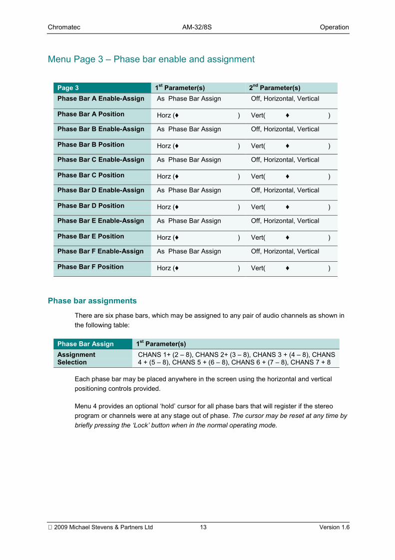
Menu Page 3 Phase bar enable and assignment
Page 3 1st Parameter(s) 2nd Parameter(s)Phase Bar A Enable-Assign As Phase Bar Assign Off, Horizontal, Vertical
Phase Bar A Position Horz (♦ ) Vert( ♦ )
Phase Bar B Enable-Assign As Phase Bar Assign Off, Horizontal, Vertical
Phase Bar B Position Horz (♦ ) Vert( ♦ )
Phase Bar C Enable-Assign As Phase Bar Assign Off, Horizontal, Vertical
Phase Bar C Position Horz (♦ ) Vert( ♦ )
Phase Bar D Enable-Assign As Phase Bar Assign Off, Horizontal, Vertical
Phase Bar D Position Horz (♦ ) Vert( ♦ )
Phase Bar E Enable-Assign As Phase Bar Assign Off, Horizontal, Vertical
Phase Bar E Position Horz (♦ ) Vert( ♦ )
Phase Bar F Enable-Assign As Phase Bar Assign Off, Horizontal, Vertical
Phase Bar F Position Horz (♦ ) Vert( ♦ )
Phase bar assignments
There are six phase bars, which may be assigned to any pair of audio channels as shown inthe following table:
Phase Bar Assign 1st Parameter(s)AssignmentSelection
CHANS 1+ (2 8), CHANS 2+ (3 8), CHANS 3 + (4 8), CHANS4 + (5 8), CHANS 5 + (6 8), CHANS 6 + (7 8), CHANS 7 + 8
Each phase bar may be placed anywhere in the screen using the horizontal and verticalpositioning controls provided.
Menu 4 provides an optional hold cursor for all phase bars that will register if the stereoprogram or channels were at any stage out of phase. The cursor may be reset at any time bybriefly pressing the Lock button when in the normal operating mode.
Chromatec AM-32/8S Operation
2009 Michael Stevens & Partners Ltd 14 Version 1.6
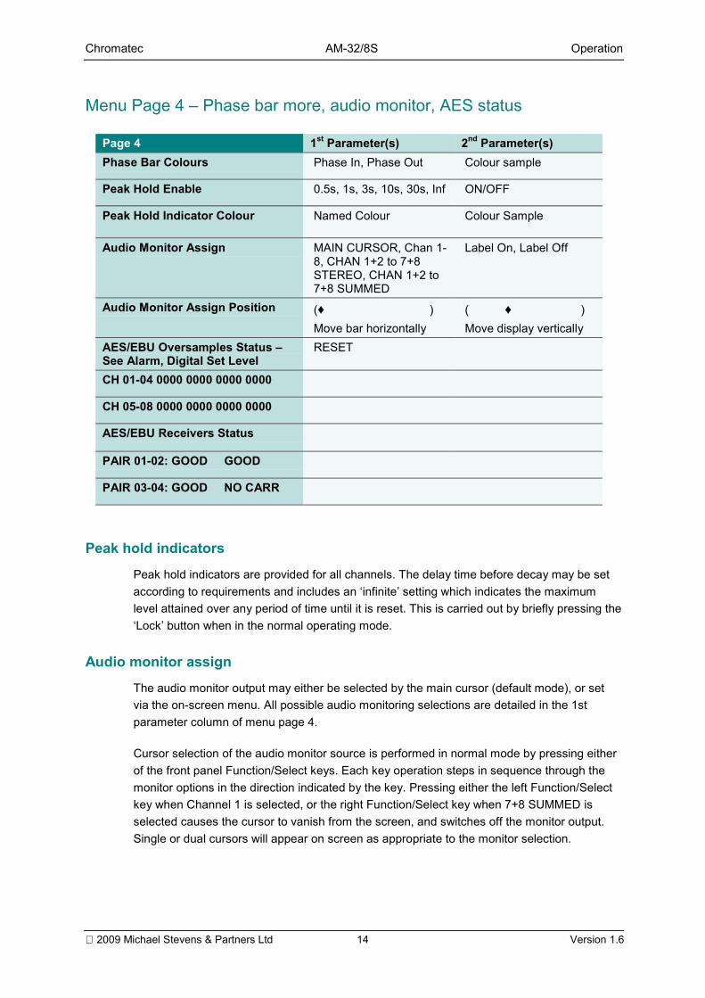
Menu Page 4 Phase bar more, audio monitor, AES status
Page 4 1st Parameter(s) 2nd Parameter(s)Phase Bar Colours Phase In, Phase Out Colour sample
Peak Hold Enable 0.5s, 1s, 3s, 10s, 30s, Inf ON/OFF
Peak Hold Indicator Colour Named Colour Colour Sample
Audio Monitor Assign MAIN CURSOR, Chan 1-8, CHAN 1+2 to 7+8STEREO, CHAN 1+2 to7+8 SUMMED
Label On, Label Off
Audio Monitor Assign Position (♦ )Move bar horizontally
( ♦ )Move display vertically
AES/EBU Oversamples Status See Alarm, Digital Set Level
RESET
CH 01-04 0000 0000 0000 0000
CH 05-08 0000 0000 0000 0000
AES/EBU Receivers Status
PAIR 01-02: GOOD GOOD
PAIR 03-04: GOOD NO CARR
Peak hold indicators
Peak hold indicators are provided for all channels. The delay time before decay may be setaccording to requirements and includes an infinite setting which indicates the maximumlevel attained over any period of time until it is reset. This is carried out by briefly pressing theLock button when in the normal operating mode.
Audio monitor assign
The audio monitor output may either be selected by the main cursor (default mode), or setvia the on-screen menu. All possible audio monitoring selections are detailed in the 1stparameter column of menu page 4.
Cursor selection of the audio monitor source is performed in normal mode by pressing eitherof the front panel Function/Select keys. Each key operation steps in sequence through themonitor options in the direction indicated by the key. Pressing either the left Function/Selectkey when Channel 1 is selected, or the right Function/Select key when 7+8 SUMMED isselected causes the cursor to vanish from the screen, and switches off the monitor output.Single or dual cursors will appear on screen as appropriate to the monitor selection.
Chromatec AM-32/8S Operation
2009 Michael Stevens & Partners Ltd 15 Version 1.6
When selecting stereo channel pairs, the cursors will automatically change in colour to red(left channel) and green (right channel). At all other times the cursor/s will assume the maincursor colour selected in menu page 2.
An on-screen audio monitor status label may be switched on or off via the menu.
Should the AM-32/8S be fitted with the Dolby Digital input card option, channels 7 and 8contain a stereo down-mix (3/2L.C.R.Ls.Rs) of the surround channels. This may bemonitored by selecting 7+8 STEREO.
A pair of balanced analogue audio monitor outputs are provided irrespective of the input cardoption fitted.
Audio monitor label
An on-screen audio monitor label may be turned on and positioned anywhere in the screen.The label displays which mono channel or stereo/summed adjacent channel(s) are directedto the balanced audio monitor outputs.
AES/EBU oversamples status
The status shown for each channel pair is dependent on the number of oversamplespermitted, as set on page 5 of the menu under Alarm, Digital Over Enable - Set Level. Thedata displayed remains and is updated until reset in the menu or the unit is switched off.
Note: RESET will flash red to indicate that both Lock and Insert On must be pressedtogether to provide a reset.
AES/EBU receiver status
The status of all incoming AES/EBU feeds is displayed on this page.
Note: NO CARR is shown if no digital audio input is connected.
Chromatec AM-32/8S Operation
2009 Michael Stevens & Partners Ltd 16 Version 1.6
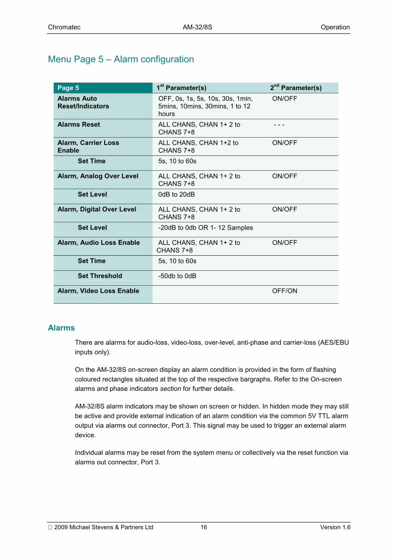
Menu Page 5 Alarm configuration
Page 5 1st Parameter(s) 2nd Parameter(s)Alarms AutoReset/Indicators
OFF, 0s, 1s, 5s, 10s, 30s, 1min,5mins, 10mins, 30mins, 1 to 12hours
ON/OFF
Alarms Reset ALL CHANS, CHAN 1+ 2 toCHANS 7+8
- - -
Alarm, Carrier LossEnable
ALL CHANS, CHAN 1+2 toCHANS 7+8
ON/OFF
Set Time 5s, 10 to 60s
Alarm, Analog Over Level ALL CHANS, CHAN 1+ 2 toCHANS 7+8
ON/OFF
Set Level 0dB to 20dB
Alarm, Digital Over Level ALL CHANS, CHAN 1+ 2 toCHANS 7+8
ON/OFF
Set Level -20dB to 0db OR 1- 12 Samples
Alarm, Audio Loss Enable ALL CHANS, CHAN 1+ 2 toCHANS 7+8
ON/OFF
Set Time 5s, 10 to 60s
Set Threshold -50db to 0dB
Alarm, Video Loss Enable OFF/ON
Alarms
There are alarms for audio-loss, video-loss, over-level, anti-phase and carrier-loss (AES/EBUinputs only).
On the AM-32/8S on-screen display an alarm condition is provided in the form of flashingcoloured rectangles situated at the top of the respective bargraphs. Refer to the On-screenalarms and phase indicators section for further details.
AM-32/8S alarm indicators may be shown on screen or hidden. In hidden mode they may stillbe active and provide external indication of an alarm condition via the common 5V TTL alarmoutput via alarms out connector, Port 3. This signal may be used to trigger an external alarmdevice.
Individual alarms may be reset from the system menu or collectively via the reset function viaalarms out connector, Port 3.
Chromatec AM-32/8S Operation
2009 Michael Stevens & Partners Ltd 17 Version 1.6
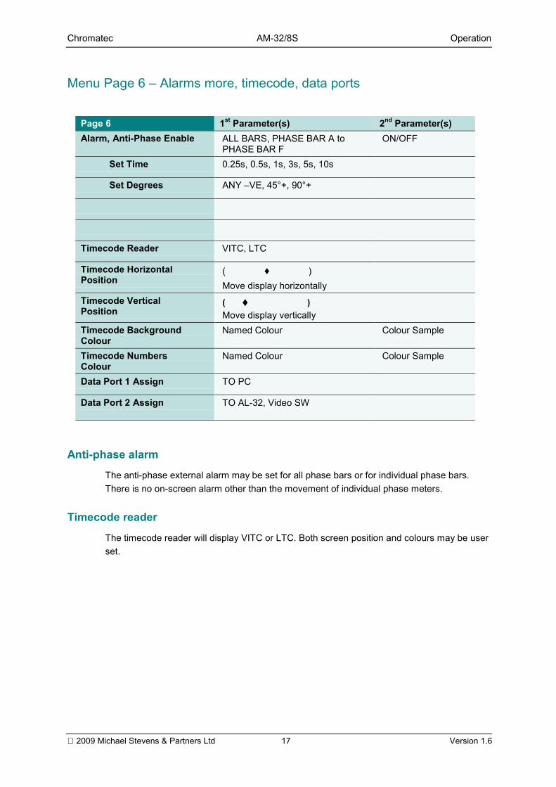
Menu Page 6 Alarms more, timecode, data ports
Page 6 1st Parameter(s) 2nd Parameter(s)Alarm, Anti-Phase Enable ALL BARS, PHASE BAR A to
PHASE BAR FON/OFF
Set Time 0.25s, 0.5s, 1s, 3s, 5s, 10s
Set Degrees ANY VE, 45°+, 90°+
Timecode Reader VITC, LTC
Timecode HorizontalPosition
( ♦ )Move display horizontally
Timecode VerticalPosition
( ♦♦♦♦ )Move display vertically
Timecode BackgroundColour
Named Colour Colour Sample
Timecode NumbersColour
Named Colour Colour Sample
Data Port 1 Assign TO PC
Data Port 2 Assign TO AL-32, Video SW
Anti-phase alarm
The anti-phase external alarm may be set for all phase bars or for individual phase bars.There is no on-screen alarm other than the movement of individual phase meters.
Timecode reader
The timecode reader will display VITC or LTC. Both screen position and colours may be userset.
Chromatec AM-32/8S Operation
2009 Michael Stevens & Partners Ltd 18 Version 1.6
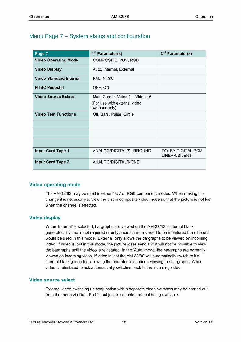
Menu Page 7 System status and configuration
Page 7 1st Parameter(s) 2nd Parameter(s)Video Operating Mode COMPOSITE, YUV, RGB
Video Display Auto, Internal, External
Video Standard Internal PAL, NTSC
NTSC Pedestal OFF, ON
Video Source Select Main Cursor, Video 1 Video 16(For use with external videoswitcher only)
Video Test Functions Off, Bars, Pulse, Circle
Input Card Type 1 ANALOG/DIGITAL/SURROUND DOLBY DIGITAL/PCMLINEAR/SILENT
Input Card Type 2 ANALOG/DIGITAL/NONE
Video operating mode
The AM-32/8S may be used in either YUV or RGB component modes. When making thischange it is necessary to view the unit in composite video mode so that the picture is not lostwhen the change is effected.
Video display
When Internal is selected, bargraphs are viewed on the AM-32/8Ss internal blackgenerator. If video is not required or only audio channels need to be monitored then the unitwould be used in this mode. External only allows the bargraphs to be viewed on incomingvideo. If video is lost in this mode, the picture loses sync and it will not be possible to viewthe bargraphs until the video is reinstated. In the Auto mode, the bargraphs are normallyviewed on incoming video. If video is lost the AM-32/8S will automatically switch to itsinternal black generator, allowing the operator to continue viewing the bargraphs. Whenvideo is reinstated, black automatically switches back to the incoming video.
Video source select
External video switching (in conjunction with a separate video switcher) may be carried outfrom the menu via Data Port 2, subject to suitable protocol being available.
Chromatec AM-32/8S Operation
2009 Michael Stevens & Partners Ltd 19 Version 1.6
Video test functions
When entering this mode all other display parameters are disabled. Basic test patterns areprovided including colour bars, 75% & 100% and a circle. Pressing the lock button forapproximately 3 seconds will reinstate the system menu where this function may be switchedoff.
Input card type
The status of the input cards fitted to the AM-32/8S is automatically displayed.
Menu Page 8 Contact Information
Contact information, as shown at the front of this manual, is displayed on menu page 8.
Chromatec AM-32/8S Installation
2009 Michael Stevens & Partners Ltd 20 Version 1.6
IInnssttaallllaattiioonnThe Chromatec AM-32/8S 1U frame may be installed in 19 inch bays with 453mm depth.Ventilation is produced in each frame with three exhaust fans on the left hand side (viewedfrom front) with intake grilles at the right.
There are also air intake vents located on the top of the frame. Frames should be installedinto bays such that airflow through these apertures is not impeded.
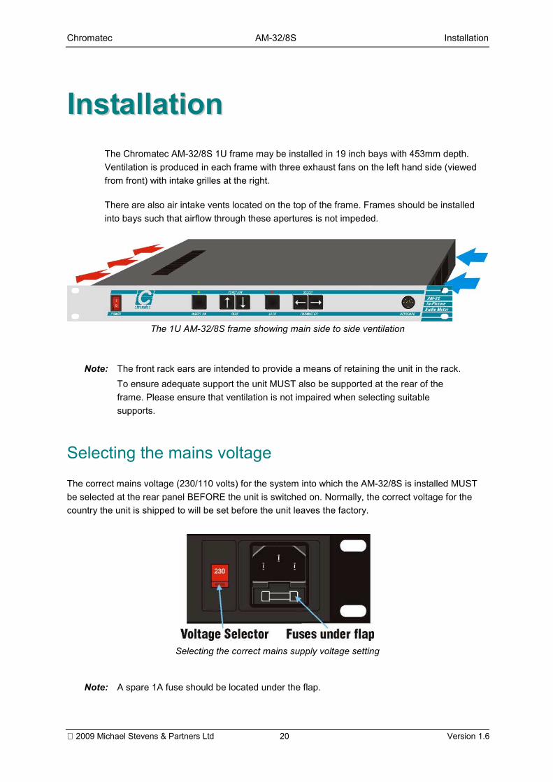
The 1U AM-32/8S frame showing main side to side ventilation
Note: The front rack ears are intended to provide a means of retaining the unit in the rack.To ensure adequate support the unit MUST also be supported at the rear of theframe. Please ensure that ventilation is not impaired when selecting suitablesupports.
Selecting the mains voltageThe correct mains voltage (230/110 volts) for the system into which the AM-32/8S is installed MUSTbe selected at the rear panel BEFORE the unit is switched on. Normally, the correct voltage for thecountry the unit is shipped to will be set before the unit leaves the factory.
Selecting the correct mains supply voltage setting
Note: A spare 1A fuse should be located under the flap.
Chromatec AM-32/8S Installation
2009 Michael Stevens & Partners Ltd 21 Version 1.6
Health and safety considerationsThe Installation and Maintenance of the Chromatec AM-32/8S In-Picture Audio Meter andAlarm System and any associated equipment, must be carried out by PERSONS SUITABLYQUALIFIED to work with equipment which may be connected to the mains supply.
The AM-32/8S MUST BE DISCONNECTED & ISOLATED FROM THE MAINS INPUT andfrom other product outputs before undertaking maintenance.
ELECTRIC SHOCK HAZARDS exist if conductive instruments, neck chains or fingers etc areplaced within the AM-32/8S or in close proximity of the input/output terminals/connectors.
Incorrect installation can cause internal components to rupture and particles to be ejectedfrom the product.
TOXIC FUME HAZARDS exist if the unit is subjected to direct flames or excessivetemperature of above 100 Degrees Centigrade ambient.
The mounting and installation of the unit must be arranged by the user to comply with allsafety regulations by the indigenous authority.
Disposal
Do not incinerate as explosive and toxic fume hazards exist. Disposal must be by dismantlingthe product to component level and disposing of each component by an approved method.
Supplied accessories
Standard accessories are as follows:
AM-32/8S with analogue or digital input card
Item Accessory1 AM-32/8S frame2 Manual3 Mains lead4 50 way D connector
Chromatec AM-32/8S Installation
2009 Michael Stevens & Partners Ltd 22 Version 1.6
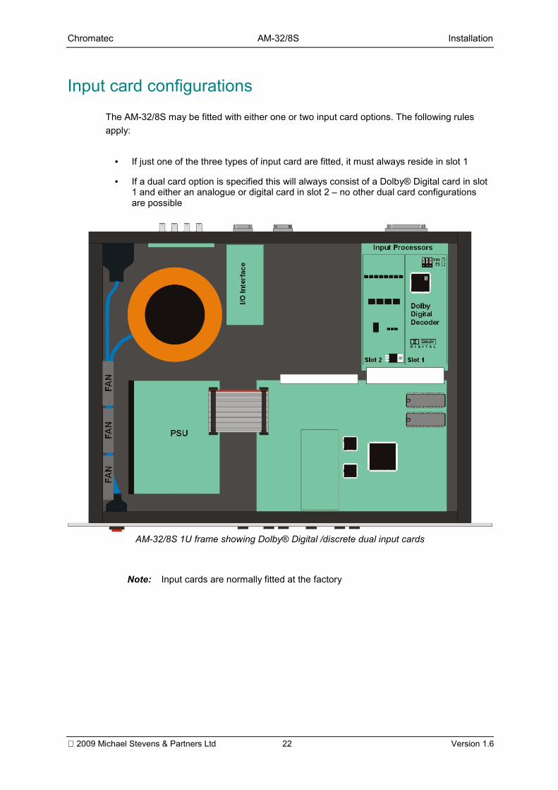
Input card configurationsThe AM-32/8S may be fitted with either one or two input card options. The following rulesapply:
• If just one of the three types of input card are fitted, it must always reside in slot 1
• If a dual card option is specified this will always consist of a Dolby® Digital card in slot1 and either an analogue or digital card in slot 2 no other dual card configurationsare possible
AM-32/8S 1U frame showing Dolby® Digital /discrete dual input cards
Note: Input cards are normally fitted at the factory
Chromatec AM-32/8S Installation
2009 Michael Stevens & Partners Ltd 23 Version 1.6
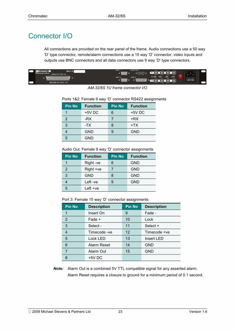
Connector I/OAll connections are provided on the rear panel of the frame. Audio connections use a 50 way'D type connector, remote/alarm connections use a 15 way D connector, video inputs andoutputs use BNC connectors and all data connectors use 9 way D type connectors.
AM-32/8S 1U frame connector I/O
Ports 1&2: Female 9 way D connector RS422 assignments
Pin No Function Pin No Function1 +5V DC 6 +5V DC2 -RX 7 +RX3 -TX 8 +TX4 GND 9 GND5 GND
Audio Out: Female 9 way D connector assignments
Pin No Function Pin No Function1 Right -ve 6 GND2 Right +ve 7 GND3 GND 8 GND4 Left -ve 9 GND5 Left +ve
Port 3: Female 15 way D connector assignments
Pin No Description Pin No Description1 Insert On 9 Fade -2 Fade + 10 Lock3 Select - 11 Select +4 Timecode -ve 12 Timecode +ve5 Lock LED 13 Insert LED6 Alarm Reset 14 GND7 Alarm Out 15 GND8 +5V DC
Note: Alarm Out is a combined 5V TTL compatible signal for any asserted alarm.Alarm Reset requires a closure to ground for a minimum period of 0.1 second.
Chromatec AM-32/8S Installation
2009 Michael Stevens & Partners Ltd 24 Version 1.6
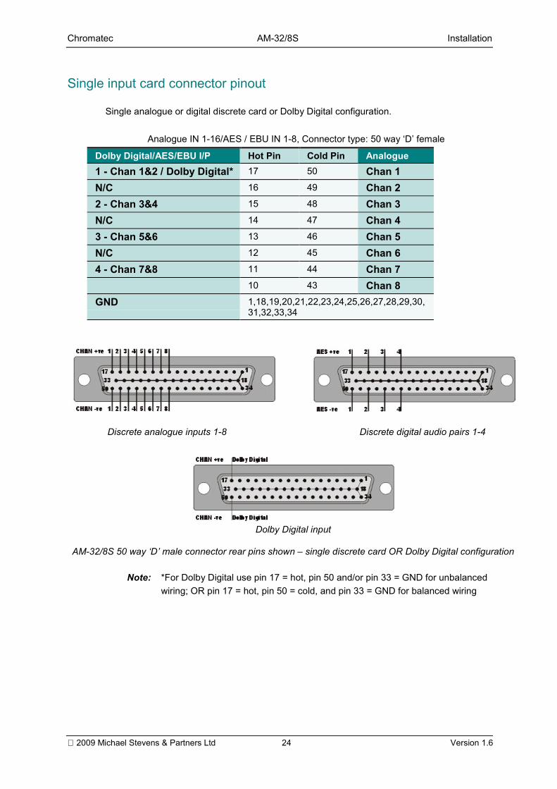
Single input card connector pinout
Single analogue or digital discrete card or Dolby Digital configuration.
Analogue IN 1-16/AES / EBU IN 1-8, Connector type: 50 way D female
Dolby Digital/AES/EBU I/P Hot Pin Cold Pin Analogue1 - Chan 1&2 / Dolby Digital* 17 50 Chan 1N/C 16 49 Chan 22 - Chan 3&4 15 48 Chan 3N/C 14 47 Chan 43 - Chan 5&6 13 46 Chan 5N/C 12 45 Chan 64 - Chan 7&8 11 44 Chan 7
10 43 Chan 8GND 1,18,19,20,21,22,23,24,25,26,27,28,29,30,
31,32,33,34
Discrete analogue inputs 1-8 Discrete digital audio pairs 1-4
Dolby Digital input
AM-32/8S 50 way D male connector rear pins shown single discrete card OR Dolby Digital configuration
Note: *For Dolby Digital use pin 17 = hot, pin 50 and/or pin 33 = GND for unbalancedwiring; OR pin 17 = hot, pin 50 = cold, and pin 33 = GND for balanced wiring
Chromatec AM-32/8S Installation
2009 Michael Stevens & Partners Ltd 25 Version 1.6
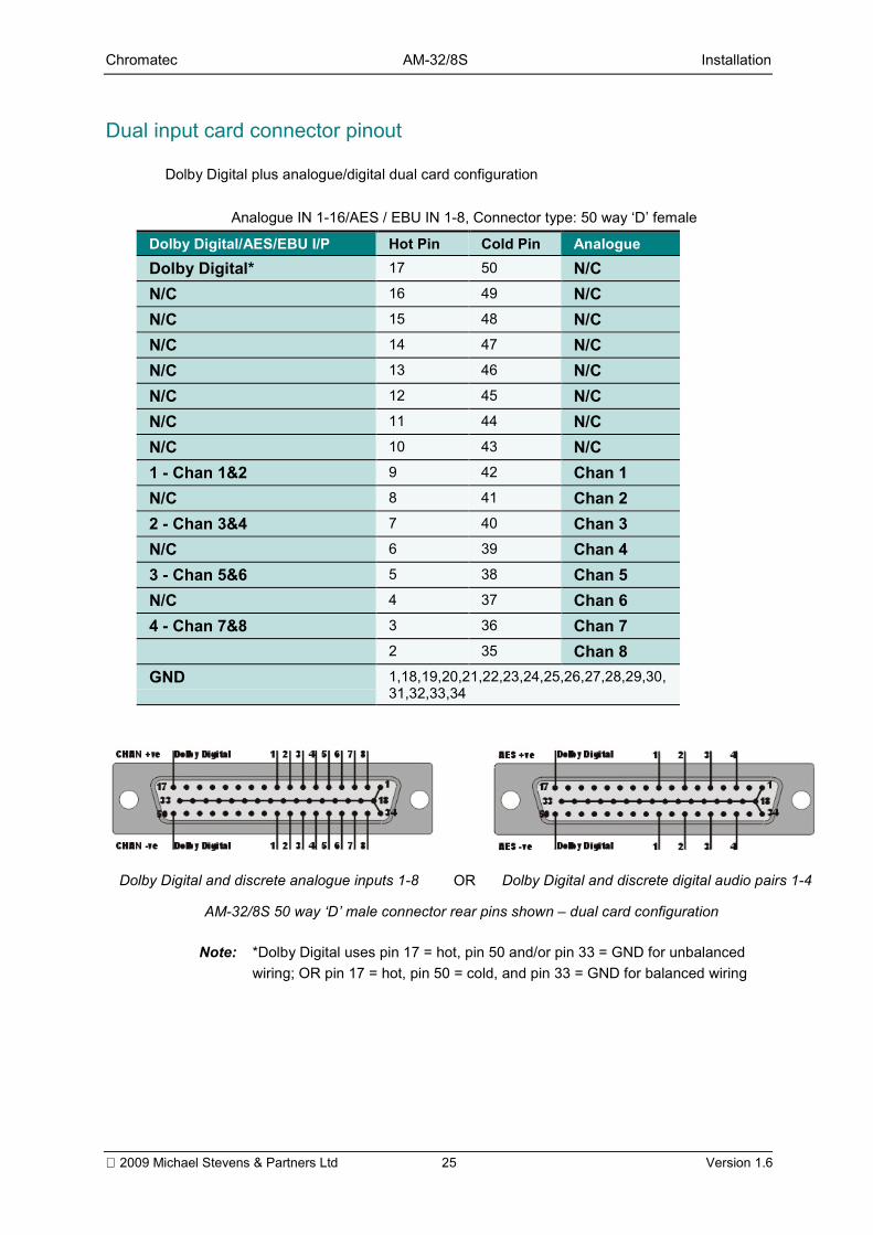
Dual input card connector pinout
Dolby Digital plus analogue/digital dual card configuration
Analogue IN 1-16/AES / EBU IN 1-8, Connector type: 50 way D female
Dolby Digital/AES/EBU I/P Hot Pin Cold Pin AnalogueDolby Digital* 17 50 N/CN/C 16 49 N/CN/C 15 48 N/CN/C 14 47 N/CN/C 13 46 N/CN/C 12 45 N/CN/C 11 44 N/CN/C 10 43 N/C1 - Chan 1&2 9 42 Chan 1N/C 8 41 Chan 22 - Chan 3&4 7 40 Chan 3N/C 6 39 Chan 43 - Chan 5&6 5 38 Chan 5N/C 4 37 Chan 64 - Chan 7&8 3 36 Chan 7
2 35 Chan 8GND 1,18,19,20,21,22,23,24,25,26,27,28,29,30,
31,32,33,34
Dolby Digital and discrete analogue inputs 1-8 OR Dolby Digital and discrete digital audio pairs 1-4
AM-32/8S 50 way D male connector rear pins shown dual card configuration
Note: *Dolby Digital uses pin 17 = hot, pin 50 and/or pin 33 = GND for unbalancedwiring; OR pin 17 = hot, pin 50 = cold, and pin 33 = GND for balanced wiring
Chromatec AM-32/8S Installation
2009 Michael Stevens & Partners Ltd 26 Version 1.6
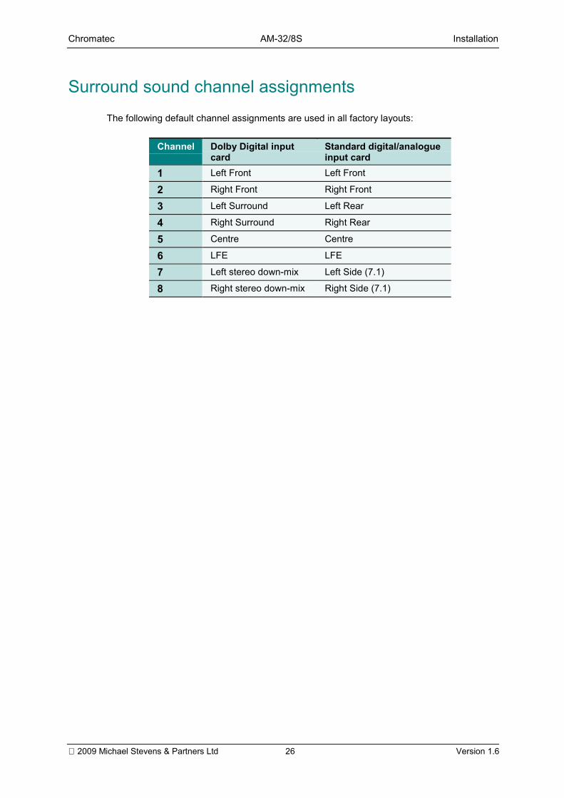
Surround sound channel assignmentsThe following default channel assignments are used in all factory layouts:
Channel Dolby Digital inputcard
Standard digital/analogueinput card
1 Left Front Left Front
2 Right Front Right Front
3 Left Surround Left Rear
4 Right Surround Right Rear
5 Centre Centre
6 LFE LFE
7 Left stereo down-mix Left Side (7.1)
8 Right stereo down-mix Right Side (7.1)
Chromatec AM-32/8S Installation
2009 Michael Stevens & Partners Ltd 27 Version 1.6
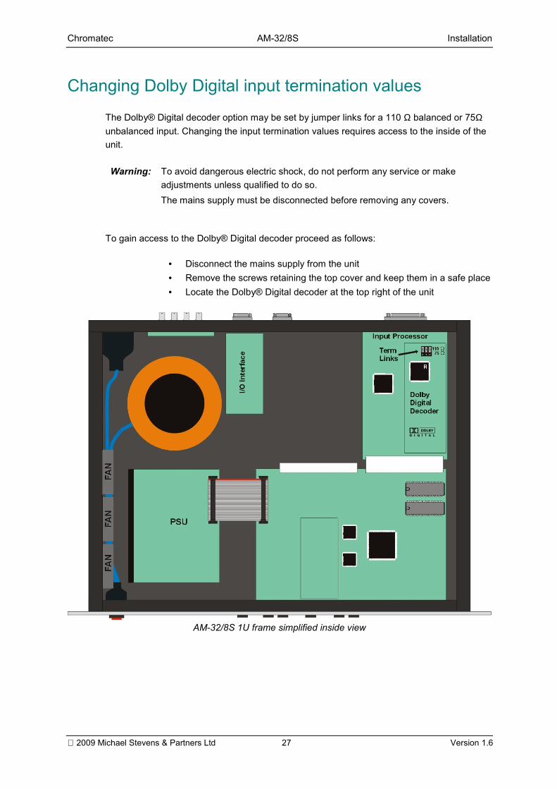
Changing Dolby Digital input termination values
The Dolby® Digital decoder option may be set by jumper links for a 110 Ω balanced or 75Ωunbalanced input. Changing the input termination values requires access to the inside of theunit.
Warning: To avoid dangerous electric shock, do not perform any service or makeadjustments unless qualified to do so.The mains supply must be disconnected before removing any covers.
To gain access to the Dolby® Digital decoder proceed as follows:
• Disconnect the mains supply from the unit• Remove the screws retaining the top cover and keep them in a safe place• Locate the Dolby® Digital decoder at the top right of the unit
AM-32/8S 1U frame simplified inside view
Chromatec AM-32/8S Installation
2009 Michael Stevens & Partners Ltd 28 Version 1.6
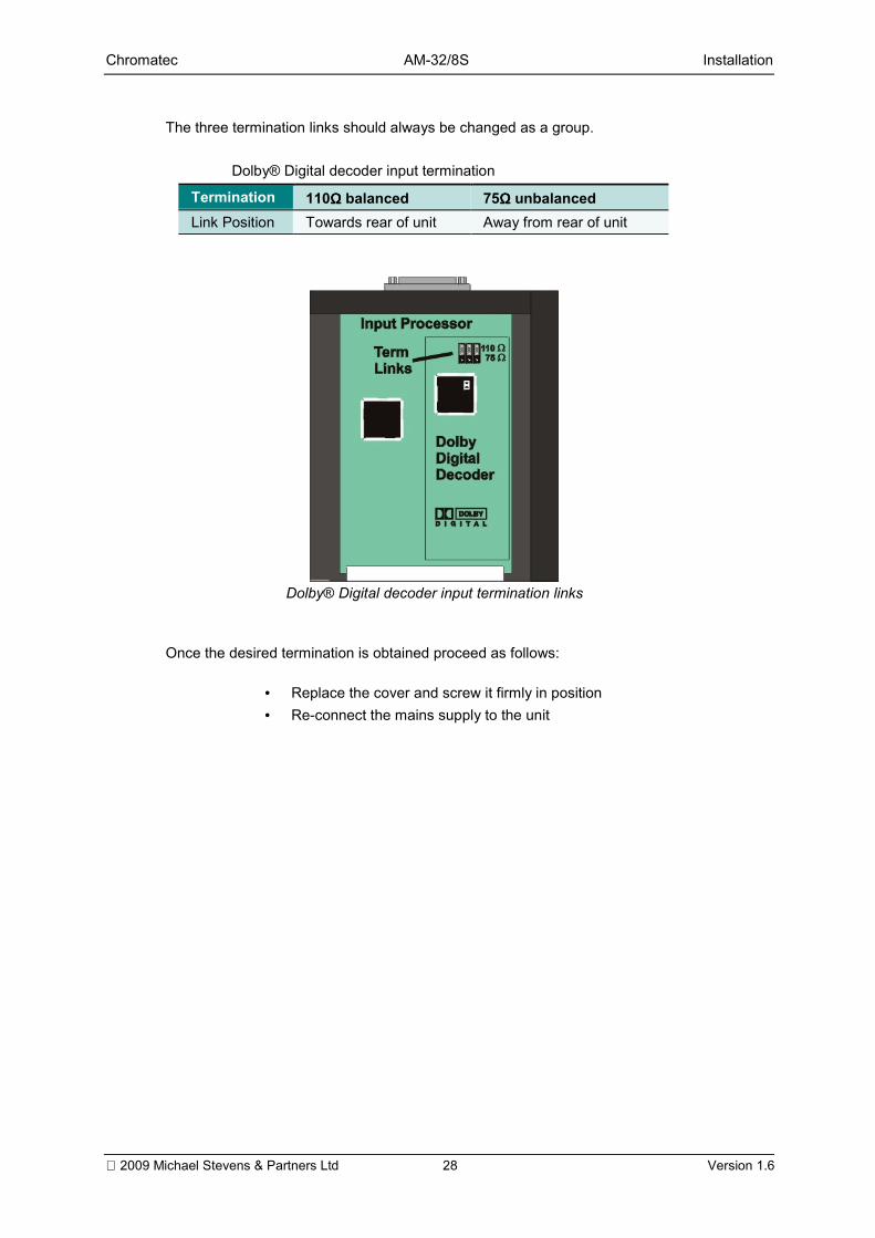
The three termination links should always be changed as a group.
Dolby® Digital decoder input termination
Termination 110Ω Ω Ω Ω balanced 75Ω Ω Ω Ω unbalancedLink Position Towards rear of unit Away from rear of unit
Dolby® Digital decoder input termination links
Once the desired termination is obtained proceed as follows:
• Replace the cover and screw it firmly in position• Re-connect the mains supply to the unit
Chromatec AM-32/8S Problem solving
2009 Michael Stevens & Partners Ltd 29 Version 1.6
PPrroobblleemm ssoollvviinnggThe power switch should illuminate red whenever mains power is supplied. Always ensurethat power is connected before using the problem solving guide. A spare fuse is supplied inspace provided in the IEC mains connector before the unit leaves the factory. Always replacethe fuse with one of the correct value as shown in the Installation section.
Sample problems and their solutions
There is no composite outputCheck that there is power to the unit and that it is turned onAn output should be seen within a few seconds of switching on
No colour information can be seenCheck that the correct TV standard has been selectedCheck the colour assignments in the configuration
The Monitor Select Cursor cannot be seenCheck that it has not been scrolled off-screen
All alarms and bargraph elements turn on in menu modeThis is done to allow AM-32/8S configuration changes to be viewed immediately
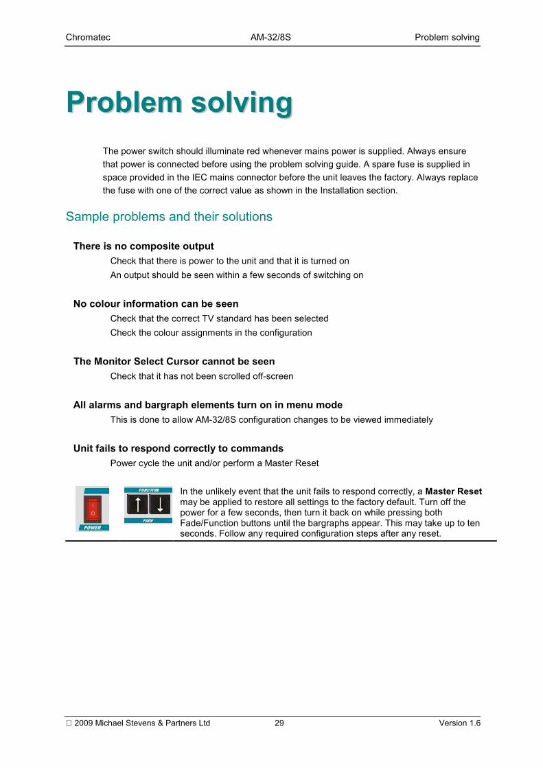
Unit fails to respond correctly to commandsPower cycle the unit and/or perform a Master Reset
In the unlikely event that the unit fails to respond correctly, a Master Resetmay be applied to restore all settings to the factory default. Turn off thepower for a few seconds, then turn it back on while pressing bothFade/Function buttons until the bargraphs appear. This may take up to tenseconds. Follow any required configuration steps after any reset.
Chromatec AM-32/8S Specification
2009 Michael Stevens & Partners Ltd 30 Version 1.6
SSppeecciiffiiccaattiioonnAnalogue inputs Input connector: 50 pole "D" type
Input impedance: 20KΩ, balancedInput sensitivity: 0dBu = 0dB scale readingInput sensitivity adjustment - coarse: +8, -3dBu in 1dB stepsInput sensitivity adjustment - fine: ±1dBu in 0.1dB stepsMax Input level: +24dBuFrequency response at -3dB points: 25Hz to 23KHzA/D converter: Stereo 18 bitSampling frequency: 48KHzRectifiers: Software full wave rectifierDetectors: Software Peak detectorAverage
Digital inputs Input connector: 50 pole "D" typeInput type: DifferentialInput compatibility: RS422Input interface: Transformerless professional AES/EBUSampling frequency: 48KHzRectifiers: Software full wave rectifierDetectors: Software sample detector
Digital inputs withDolby® Digital inputcard
Input connector:1 x 50 pole D with integral BNC for unbalanced inputs1 x 50 way D with cable terminating in female XLR for balanced inputsNote: The Dolby Digital input always uses channel 1 (pin 17) of the 50 wayconnectorInput type: Differential (balanced inputs only)Input compatibility: RS422Input interface: Transformerless professional AES/EBUSampling frequency: 32, 44.1, 48KHz detected via inputInput data rate: 32kbs 640kbsRectifiers: Software full wave rectifierDetectors: Software sample detector
Video inputs Input connector: 75 Ohm BNCComposite video auto PAL/NTSCComponent YUV/RGB switchable
Chromatec AM-32/8S Specification
2009 Michael Stevens & Partners Ltd 31 Version 1.6
Video outputs Output connector: 75 Ohm BNC Composite video PAL/NTSCComponent YUV/RGB switchable
Scales and BallisticsNORDIC: Overall dynamic range: 54dB (+12 to -42dB)
Attack time: 10mSecDecay time: 1.7Sec per 20dB decay
DIN PPM: Overall dynamic range: 55dB (+5 to -50dB)Attack time: 10mSecDecay time: 1.5Sec per 20dB decay
BBC PPM: Overall dynamic range: 24dB +3dB down "Mark 1" (+12 to-12dB)Attack time: 10mSecDecay time: 2.8Sec per 24dB decay (from "Mark 7" to "Mark 1")
VU: Overall dynamic range: 23dB (+3 to -20dB)Attack time: 300mSec (from v2.1)
Decay time: 300mSec per 20dB decay (from v2.1)
VU EXT: Overall dynamic range: 80dB (+10 to -70dB)Attack time: 300mSec (from v2.1)
Decay time: 300mSec per 20dB decay (from v2.1)
Decay time: 1.0Sec per 40dB decayAES/EBU: Overall dynamic range: 60dB (0 to -60dB)
Attack time: One sampleDecay time: 1.5Sec per 20dB decay
Phase CorrelationDisplay
Attack time: 0.4Sec for zero to ±1 deviationDecay time: 0.4Sec for ±1 to zero deviationInput dynamic range: 45dBMinimum input level: -45dBu
Housing 19 Rack Mount: 1U high.Outline Dimensions: 484mm(W) x 453mm(D) x 44.5mm(H)
Power 110V / 60 Hz or 230V / 50 Hz, switch selected
Environmental Temperature 0°C to 30°C Humidity 70% max.
Front panel Power on/off, 6 configuration buttons
Rear panel Video I/O BNC connector, 2 x RS422, Remote, Audio Out connector and50 way audio input connector