Embed Size (px)
Citation preview

from page 606
from page 606
from page 602 from page 534
from page 612
from page 613from page 609
from page 586


Con
nect
ing
clam
ps
586
Models all rights reserved in accordance with the law. Always mention the source when reproducing our drawings.
1
2
3
4
5
6
7
8
9
10
11
12
13
14
15
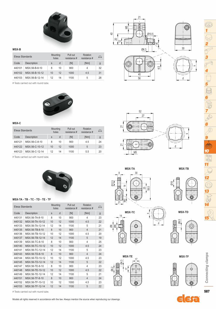
Features and applicationsThe geometry of the holes of MSX. series connecting clamps are designed to fit both tubes with round cross section and tubes with square cross section; the latter prevents the elements from rotating (see Fig. 1).Assembly instructions1) Fit the base by means of 2 M6 cylindrical-head screws with hexagon
socket (not supplied).2) Fit the connecting tube into the hole of the base and clamp it by
screwing the set screw. Suggested tightening torque 5 Nm.3) Insert the T-shaped clamp which allows the assembly of another
connecting tube.4) Fit the other connecting tube into the hole of the T-shaped clamp.5) Fit onto the connecting tube the desired device clamp chosen among
the six available ones. After the positioning of the components, clamp them by screwing the set screws. Suggested tightening torque 5 Nm.
• Standard components- MSX-B base:glass-fibre reinforced polyamide based (PA) technopolymer, black colour, matte finish.
Fitting by means of a stainless steel M5 cylindrical-head screw with hexagon socket and nut.
- MSX-C T-shaped clamp:glass-fibre reinforced technopolymer, black colour, matte finish.
Fitting by means of stainless steel M5 cylindrical-head screws with hexagon socket and nuts.
- MSX-TA-TB-TC-TD-TE-TF device clamps:glass-fibre reinforced technopolymer, black colour, matte finish.
Fitting by means of a stainless steel M5 cylindrical-head screw with hexagon socket and nut.
Connecting clamps
Design
MSX.
587
Con
nect
ing
clam
ps
Models all rights reserved in accordance with the law. Always mention the source when reproducing our drawings.
1
2
3
4
5
6
7
8
9
10
11
12
13
14
15
Elesa StandardsMounting
holesPull out
resistance #Rotation
resistance # �
Code Description s d [N] [Nm] g
440101 MSX.56-B-8-10 8 10 900 4 32
440102 MSX.56-B-10-12 10 12 1000 4.5 31
440103 MSX.56-B-12-14 12 14 1100 5 28
# Tests carried out with round tube.
MSX-B
Elesa StandardsMounting
holesPull out
resistance #Rotation
resistance # �
Code Description s d [N] [Nm] g
440121 MSX.56-C-8-10 8 10 900 4.5 24
440122 MSX.56-C-10-12 10 12 1000 5 23
440123 MSX.56-C-12-14 12 14 1100 5.5 20
Elesa StandardsMounting
holesPull out
resistance #Rotation
resistance # �
Code Description s d [N] [Nm] g
440131 MSX.56-TA-8-10 8 10 900 4 23
440132 MSX.56-TA-10-12 10 12 1000 4.5 22
440133 MSX.56-TA-12-14 12 14 1100 5 21
440135 MSX.56-TB-8-10 8 10 900 4 21
440136 MSX.56-TB-10-12 10 12 1000 4.5 20
440137 MSX.56-TB-12-14 12 14 1100 5 19
440139 MSX.56-TC-8-10 8 10 900 4 25
440140 MSX.56-TC-10-12 10 12 1000 4.5 24
440141 MSX.56-TC-12-14 12 14 1100 5 23
440143 MSX.56-TD-8-10 8 10 900 4 24
440144 MSX.56-TD-10-12 10 12 1000 4.5 23
440145 MSX.56-TD-12-14 12 14 1100 5 22
440147 MSX.56-TE-8-10 8 10 900 4 23
440148 MSX.56-TE-10-12 10 12 1000 4.5 22
440149 MSX.56-TE-12-14 12 14 1100 5 21
440151 MSX.56-TF-8-10 8 10 900 4 24
440152 MSX.56-TF-10-12 10 12 1000 4.5 23
440153 MSX.56-TF-12-14 12 14 1100 5 22
# Tests carried out with round tube.
# Tests carried out with round tube.
MSX-C
MSX-TA - TB - TC - TD - TE - TF

Con
nect
ing
clam
ps
588
Models all rights reserved in accordance with the law. Always mention the source when reproducing our drawings.
1
2
3
4
5
6
7
8
9
10
11
12
13
14
15
Features and applicationsMSR. connecting clamps, designed according to ELESA patent, allow an easy and efficient connection between the components, preventing the risk of rotating freely. The system allows the axial, perpendicular or angled positioning of the connecting tube to the base.Advantages- The slot-shaped connecting tube preventing free rotation.- Tube and components clamped by the aid of only one screw.- Easy adjustments by five degrees of freedom of the clamped devices
(see drawing).- Lack of cavities to avoid the deposit of dirt and undesired substances.- Easy identification of the clamped device using different coloured caps
on the base.
• Standard components- MSR.60-B base:glass-fibre reinforced polyamide based (PA) technopolymer, black colour, matte finish.
- CC-MSR.60 screw covers: technopolymer in six colours, glossy finish.
Supplied, push-fit assembly, removable by a screwdriver.
Available also as accessories sold separately (see table).
- MSR.60-C T-shaped clamp:glass-fibre reinforced technopolymer, black colour, matte finish.
- MSR.60-TA-TB-TC-TD-TE-TF device clamps:glass-fibre reinforced technopolymer, black colour, matte finish.
- MSR.60-T13 connecting tubes:aluminium profile available with standard lengths from 100 to 2000 mm. On request and for sufficient quantities other lengths are available.
- Connecting tube closing caps:glass-fibre reinforced technopolymer, black colour, matte finish.
Supplied, push-fit assembly.
To be ordered also separately (code 440016 description TC13-MSR.60).
Connecting clamps
MSR.
Code Description Caps per
440011-* CC-MSR.60-* MSR.60-B
* Complete with colour index (C9, C2,...., C6).
Assembly instructions1) Assembly the base by means of 2 M6 cylindrical head screws with
hexagon socket (not supplied).2) Fit one of the closing caps to the end of the connecting tube by
tapping gently with a plastic mallet until firmly in place. Be careful not to assemble the cap to the end fitted to the base.
3) Insert the connecting tube in the shaped hole of the base and clamp it by screwing the set screw. Suggested tightening torque 5 Nm.
4) Insert the t-shaped clamp which allows the assembly of another connecting tube.
5) Fit the closing caps to the connecting tube.6) Insert the connecting tube in the shaped hole of the t-shaped clamp.7) Fit on the connecting tube the proper device clamp, chosen within
the six available. After the positioning of the components, clamp them by screwing the set screws. Suggested tightening torque 3 Nm. We recommend no to exceed this value
8) Once the adjustment has been set, fit the screw covers on the base.
Design

589
Con
nect
ing
clam
ps
Models all rights reserved in accordance with the law. Always mention the source when reproducing our drawings.
1
2
3
4
5
6
7
8
9
10
11
12
13
14
15
Elesa Standards Pull out resistance �
Code Description [N] g
440001-* MSR.60-B-* 300 50
Elesa Standards Pull out resistance �
Code Description [N] g
440021 MSR.60-C 300 19
Elesa Standards �
Code Description g
440050 MSR.60-T13-100 20
440055 MSR.60-T13-150 28
440060 MSR.60-T13-200 36
440065 MSR.60-T13-250 44
440070 MSR.60-T13-300 52
440200* MSR.60-T13-2000* 320
Elesa Standards Pull out resistance �
Code Description [N] g
440031 MSR.60-TA 300 18
440032 MSR.60-TB 300 17
440033 MSR.60-TC 300 19
440034 MSR.60-TD 300 18
440035 MSR.60-TE 300 18
440036 MSR.60-TF 300 20
* Supplied without closing caps.
MSR.60-B
MSR.60-C
MSR.60-T13
MSR.60-TA - TB - TC - TD - TE - TF

Con
nect
ing
clam
ps
590
Models all rights reserved in accordance with the law. Always mention the source when reproducing our drawings.
1
2
3
4
5
6
7
8
9
10
11
12
13
14
15
Dimension table keyd = hole diameter for shaft tolerance h11.d1= holes for clamping screws with threading as indicated in the table.d2= clamping screws which can be replaced with GN 511 clamping kit (see page 599).f = fixing holes centre distance: it allows matching and fixing to MSM-I connecting clamps (see page 595) and MSM-P flanged bolts (see page 598).
• MaterialAluminium.
• Clamping screwsAISI 304 stainless steel with hexagon socket.
• Standard executions- MSM-B-ANB: anodised aluminium, black colour.- MSM-B-MT: natural aluminium, matte fi nish.
Base for connecting clamps
MSM-B
Elesa Standards Main dimensions GN 511 clamping kit for d2
�
Code Description d L D H b d1 d2 h1 h2 f s g
500001 MSM-B-8-ANB 8 29 31.5 20 14 M4 M4 7 7 22 - GN 511-M4-14 23
500005 MSM-B-10-ANB 10 35 38 24 16 M5 M5 8 8 27 8 GN 511-M5-16 36
500009 MSM-B-12-ANB 12 35 38 25 16 M5 M5 8 8 27 10 GN 511-M5-16 33
500013 MSM-B-15-ANB 15 41 45 30 20 M6 M6 10 10 32 12 GN 511-M 6-20 57
500017 MSM-B-16-ANB 16 41 45 31 20 M6 M6 10 10 32 - GN 511-M6-20 57
500021 MSM-B-20-ANB 20 44 50 35 25 M6 M6 12.5 12.5 36 16 GN 511-M6-25 80
500003 MSM-B-8-MT 8 29 31.5 20 14 M4 M4 7 7 22 - GN 511-M4-14 23
500007 MSM-B-10-MT 10 35 38 24 16 M5 M5 8 8 27 8 GN 511-M5-16 36
500011 MSM-B-12-MT 12 35 38 25 16 M5 M5 8 8 27 10 GN 511-M5-16 33
500015 MSM-B-15-MT 15 41 45 30 20 M6 M6 10 10 32 12 GN 511-M6-20 57
500019 MSM-B-16-MT 16 41 45 31 20 M6 M6 10 10 32 - GN 511-M6-20 57
500023 MSM-B-20-MT 20 44 50 35 25 M6 M6 12.5 12.5 36 16 GN 511-M6-25 76
MSM-B-ANB
MSM-B-MT

591
Con
nect
ing
clam
ps
Models all rights reserved in accordance with the law. Always mention the source when reproducing our drawings.
1
2
3
4
5
6
7
8
9
10
11
12
13
14
15
Dimension table keyd = hole diameter for shaft tolerance h11. d1= clamping screws which can be replaced with GN 511 clamping kit (see page 599).
• MaterialAluminium.
• Clamping screwsAISI 304 stainless steel with hexagon socket.
• Standard executions- MSM-C-ANB: anodised aluminium, black colour. - MSM-C-MT: natural aluminium, matte fi nish.
Two-way connecting clamps
MSM-C
Elesa Standards Main dimensions GN 511 clamping kit for d1
�
Code Description d L B d1 f f1 s g
500051 MSM-C-8-8-ANB 8 37 14 M4 13.5 10 - GN 511-M4-14 16
500055 MSM-C-10-10-ANB 10 46 16 M5 17 12 8 GN 511-M5-16 25
500059 MSM-C-12-12-ANB 12 48 16 M5 17 14 10 GN 511-M5-16 24
500063 MSM-C-15-15-ANB 15 58 20 M6 20.5 17 12 GN 511-M6-20 44
500067 MSM-C-16-16-ANB 16 59 20 M6 20.5 18 - GN 511-M6-20 43
500071 MSM-C-20-20-ANB 20 65 25 M6 21.5 22 16 GN 511-M6-25 67
500053 MSM-C-8-8-MT 8 37 14 M4 13.5 10 - GN 511-M4-14 16
500057 MSM-C-10-10-MT 10 46 16 M5 17 12 8 GN 511-M5-16 25
500061 MSM-C-12-12-MT 12 48 16 M5 17 14 10 GN 511-M5-16 23
500065 MSM-C-15-15-MT 15 58 20 M6 20.5 17 12 GN 511-M6-20 44
500069 MSM-C-16-16-MT 16 59 20 M6 20.5 18 - GN 511-M6-20 43
500073 MSM-C-20-20-MT 20 65 25 M6 21.5 22 16 GN 511-M6-25 67
MSM-C-ANB
MSM-C-MT

Con
nect
ing
clam
ps
592
Models all rights reserved in accordance with the law. Always mention the source when reproducing our drawings.
1
2
3
4
5
6
7
8
9
10
11
12
13
14
15
Features and applicationsMSM-F connecting clamps have been designed in order to be used with MSM-LA (see page 596) and MSM-LB (see page 597) sensor holders.Dimension table keyd = hole diameter for shaft tolerance h11. d1= clamping screws which can be replaced with GN 511 clamping kit (see page 599).
• MaterialAluminium.
• Clamping screwsAISI 304 stainless steel with hexagon socket.
• Standard executions- MSM-F-ANB: anodised aluminium, black colour. - MSM-F-MT: natural aluminium, matte fi nish.
Clamps for fixing sensor holders
MSM-F
Elesa Standards Main dimensions GN 511 clamping kit for d1
�
Code Description d d2 L B d1 f f1 m s g
500101 MSM-F-8-M5-ANB 8 M5 25 14 M4 13.5 7.5 - - GN 511-M4-14 11
500105 MSM-F-10-M5-ANB 10 M5 30 16 M5 17 8 - 8 GN 511-M5-16 16
500109 MSM-F-10-M6-ANB 10 M6 30 16 M5 17 8 - 8 GN 511-M5-16 20
500113 MSM-F-10-M8-ANB 10 M8 30 16 M5 17 8 - 8 GN 511-M5-16 16
500117 MSM-F-12-M5-ANB 12 M5 32 16 M5 17 9 - 10 GN 511-M5-16 16
500121 MSM-F-12-M6-ANB 12 M6 32 16 M5 17 9 - 10 GN 511-M5-16 37
500125 MSM-F-12-M8-ANB 12 M8 32 16 M5 17 9 - 10 GN 511-M5-16 17
500129 MSM-F-15-M6-ANB 15 M6 40 20 M6 20.5 12 14 12 GN 511-M6-20 20
500133 MSM-F-15-M8-ANB 15 M8 40 20 M6 20.5 12 14 12 GN 511-M6-20 31
500137 MSM-F-16-M6-ANB 16 M6 40 20 M6 20.5 11.5 14 - GN 511-M6-20 31
500141 MSM-F-16-M8-ANB 16 M8 40 20 M6 20.5 11.5 14 - GN 511-M6-20 30
500145 MSM-F-20-M8-ANB 20 M8 45 25 M6 21.5 12 17 16 GN 511-M6-25 51
500149 MSM-F-20-M10-ANB 20 M10 45 25 M6 21.5 12 17 16 GN 511-M6-25 50
500103 MSM-F-8-M5-MT 8 M5 25 14 M4 13.5 7.5 - - GN 511-M4-14 11
500107 MSM-F-10-M5-MT 10 M5 30 16 M5 17 8 - 8 GN 511-M5-16 16
500111 MSM-F-10-M6-MT 10 M6 30 16 M5 17 8 - 8 GN 511-M5-16 20
500115 MSM-F-10-M8-MT 10 M8 30 16 M5 17 8 - 8 GN 511-M5-16 16
500119 MSM-F-12-M5-MT 12 M5 32 16 M5 17 9 - 10 GN 511-M5-16 16
500123 MSM-F-12-M6-MT 12 M6 32 16 M5 17 9 - 10 GN 511-M5-16 16
500127 MSM-F-12-M8-MT 12 M8 32 16 M5 17 9 - 10 GN 511-M5-16 15
500131 MSM-F-15-M6-MT 15 M6 40 20 M6 20.5 12 14 12 GN 511-M6-20 20
500135 MSM-F-15-M8-MT 15 M8 40 20 M6 20.5 12 14 12 GN 511-M6-20 31
500139 MSM-F-16-M6-MT 16 M6 40 20 M6 20.5 11.5 14 - GN 511-M6-20 31
500143 MSM-F-16-M8-MT 16 M8 40 20 M6 20.5 11.5 14 - GN 511-M6-20 30
500147 MSM-F-20-M8-MT 20 M8 45 25 M6 21.5 12 17 16 GN 511-M6-25 51
500151 MSM-F-20-M10-MT 20 M10 45 25 M6 21.5 12 17 16 GN 511-M6-25 50
MSM-F-ANB
MSM-F-MT
593
Con
nect
ing
clam
ps
Models all rights reserved in accordance with the law. Always mention the source when reproducing our drawings.
1
2
3
4
5
6
7
8
9
10
11
12
13
14
15
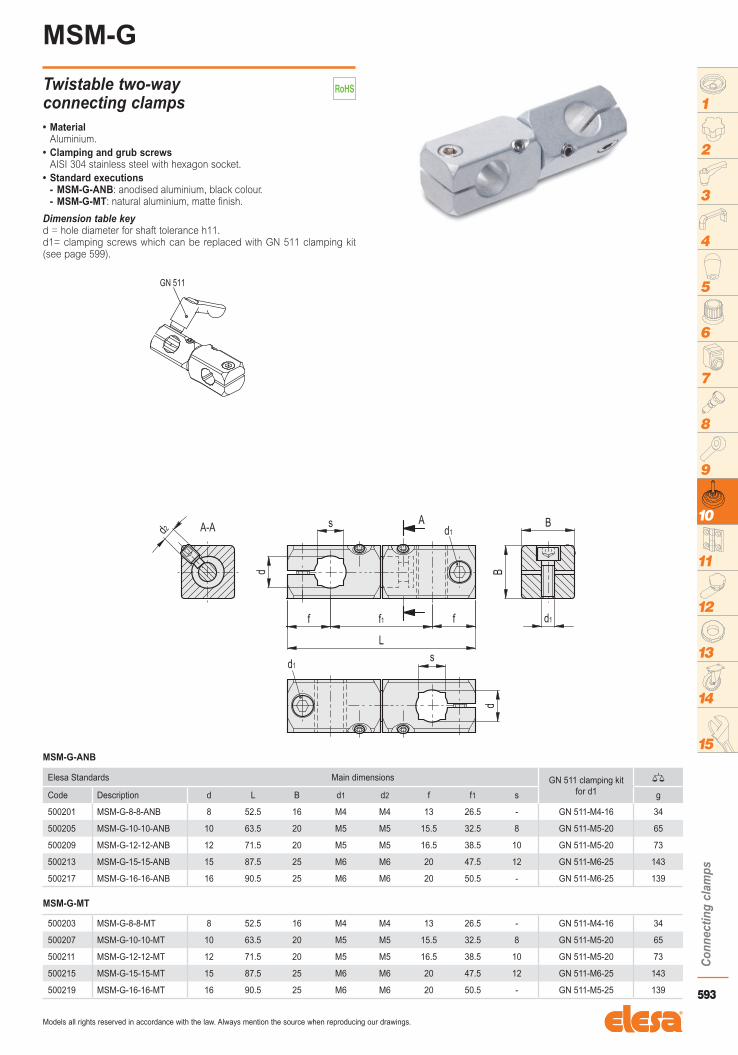
Dimension table keyd = hole diameter for shaft tolerance h11. d1= clamping screws which can be replaced with GN 511 clamping kit (see page 599).
• MaterialAluminium.
• Clamping and grub screwsAISI 304 stainless steel with hexagon socket.
• Standard executions- MSM-G-ANB: anodised aluminium, black colour. - MSM-G-MT: natural aluminium, matte fi nish.
Twistable two-way connecting clamps
MSM-G
Elesa Standards Main dimensions GN 511 clamping kit for d1
�
Code Description d L B d1 d2 f f1 s g
500201 MSM-G-8-8-ANB 8 52.5 16 M4 M4 13 26.5 - GN 511-M4-16 34
500205 MSM-G-10-10-ANB 10 63.5 20 M5 M5 15.5 32.5 8 GN 511-M5-20 65
500209 MSM-G-12-12-ANB 12 71.5 20 M5 M5 16.5 38.5 10 GN 511-M5-20 73
500213 MSM-G-15-15-ANB 15 87.5 25 M6 M6 20 47.5 12 GN 511-M6-25 143
500217 MSM-G-16-16-ANB 16 90.5 25 M6 M6 20 50.5 - GN 511-M6-25 139
500203 MSM-G-8-8-MT 8 52.5 16 M4 M4 13 26.5 - GN 511-M4-16 34
500207 MSM-G-10-10-MT 10 63.5 20 M5 M5 15.5 32.5 8 GN 511-M5-20 65
500211 MSM-G-12-12-MT 12 71.5 20 M5 M5 16.5 38.5 10 GN 511-M5-20 73
500215 MSM-G-15-15-MT 15 87.5 25 M6 M6 20 47.5 12 GN 511-M6-25 143
500219 MSM-G-16-16-MT 16 90.5 25 M6 M6 20 50.5 - GN 511-M5-25 139
MSM-G-ANB
MSM-G-MT

Con
nect
ing
clam
ps
594
Models all rights reserved in accordance with the law. Always mention the source when reproducing our drawings.
1
2
3
4
5
6
7
8
9
10
11
12
13
14
15
Dimension table keyd = hole diameter for shaft tolerance h11. d1= clamping screws which can be replaced with GN 511 clamping kit (see page 599).
• MaterialAluminium.
• Clamping and grub screwsAISI 304 stainless steel with hexagon socket.
• Standard executionsWith hole tolerance H9:
- MSM-H-A-ANB: anodised aluminium, black colour. - MSM-H-A-MT: natural aluminium, matte fi nish.With zinc-plated steel bolt tolerance h11:
- MSM-H-W-ANB: anodised aluminium, black colour. - MSM-H-W-MT: natural aluminium, matte fi nish.
Connecting clamps
MSM-H
Elesa Standards Main dimensions GN 511 clamping kit for d1
�
Code Description d L B d1 d2 d3 H9 p d4 h11 l f l1 s g
500251 MSM-H-8-8-A-ANB 8 26 16 M4 M4 8 8 - - 13 5.5 - GN 511-M4-16 20
500259 MSM-H-10-10-A-ANB 10 31.5 20 M5 M5 10 10 - - 15.5 7 8 GN 511-M5-20 150
500267 MSM-H-12-12-A-ANB 12 35.5 20 M5 M5 12 12 - - 16.5 8 10 GN 511-M5-20 28
500275 MSM-H-15-15-A-ANB 15 43.5 25 M6 M6 15 15 - - 20 10 12 GN 511-M6-25 54
500283 MSM-H-16-16-A-ANB 16 45 25 M6 M6 16 16 - - 20 11 - GN 511-M6-25 54
500253 MSM-H-8-8-A-MT 8 26 16 M4 M4 8 8 - - 13 5.5 - GN 511-M4-16 20
500261 MSM-H-10-10-A-MT 10 31.5 20 M5 M5 10 10 - - 15.5 7 8 GN 511-M5-20 150
500269 MSM-H-12-12-A-MT 12 35.5 20 M5 M5 12 12 - - 16.5 8 10 GN 511-M5-20 28
500277 MSM-H-15-15-A-MT 15 43.5 25 M6 M6 15 15 - - 20 10 12 GN 511-M6-25 54
500285 MSM-H-16-16-A-MT 16 45 25 M6 M6 16 16 - - 20 11 - GN 511-M6-25 54
500255 MSM-H-8-8-W-ANB 8 26 16 M4 M4 - - 8 16 13 5.5 - GN 511-M4-16 20
500263 MSM-H-10-10-W-ANB 10 31.5 20 M5 M5 - - 10 17 15.5 7 8 GN 511-M5-20 150
500271 MSM-H-12-12-W-ANB 12 35.5 20 M5 M5 - - 12 19 16.5 8 10 GN 511-M5-20 28
500279 MSM-H-15-15-W-ANB 15 43.5 25 M6 M6 - - 15 21 20 10 12 GN 511-M6-25 54
500287 MSM-H-16-16-W-ANB 16 45 25 M6 M6 - - 16 24 20 11 - GN 511-M6-25 54
500257 MSM-H-8-8-W-MT 8 26 16 M4 M4 - - 8 16 13 5.5 - GN 511-M4-16 20
500265 MSM-H-10-10-W-MT 10 31.5 20 M5 M5 - - 10 17 15.5 7 8 GN 511-M5-20 150
500273 MSM-H-12-12-W-MT 12 35.5 20 M5 M5 - - 12 19 16.5 8 10 GN 511-M5-20 28
500281 MSM-H-15-15-W-MT 15 43.5 25 M6 M6 - - 15 21 20 10 12 GN 511-M6-25 54
500289 MSM-H-16-16-W-MT 16 45 25 M6 M6 - - 16 24 20 11 - GN 511-M6-25 54
MSM-H-A-ANB
MSM-H-A-MT
MSM-H-W-ANB
MSM-H-W-MT

595
Con
nect
ing
clam
ps
Models all rights reserved in accordance with the law. Always mention the source when reproducing our drawings.
1
2
3
4
5
6
7
8
9
10
11
12
13
14
15
Dimension table keyd = hole diameter for shaft tolerance h11. d1= holes for clamping screws with threading as indicated in the table or for GN 511 (see page 599) clamping kit. f = fixing holes centre distance: it allows matching and fixing to MSM-B (see page 590) connecting clamps and MSM-P (see page 598) flanged bolts.
• MaterialAluminium.
• Standard executions- MSM-I-ANB: anodised aluminium, black colour. - MSM-I-MT: natural aluminium, matte fi nish.
Connecting clamps
MSM-I
Elesa Standards Main dimensions GN 511 clamping kit for d1
�
Code Description d L B d1 f s g
500301 MSM-I-8-ANB 8 31.5 14 M4 22 - GN 511-M4-20 11
500305 MSM-I-10-ANB 10 38 16 M5 27 8 GN 511-M5-25 18
500309 MSM-I-12-ANB 12 38 16 M5 27 10 GN 511-M5-25 20
500313 MSM-I-15-ANB 15 45 20 M6 32 12 GN 511-M6-25 31
500317 MSM-I-16-ANB 16 45 20 M6 32 - GN 511-M6-25 29
500321 MSM-I-20-ANB 20 50 25 M6 36 16 GN 511-M6-32 52
500303 MSM-I-8-MT 8 31.5 14 M4 22 - GN 511-M4-20 11
500307 MSM-I-10-MT 10 38 16 M5 27 8 GN 511-M5-25 18
500311 MSM-I-12-MT 12 38 16 M5 27 10 GN 511-M5-25 37
500315 MSM-I-15-MT 15 45 20 M6 32 12 GN 511-M6-25 40
500319 MSM-I-16-MT 16 45 20 M6 32 - GN 511-M6-25 29
500323 MSM-I-20-MT 20 50 25 M6 36 16 GN 511-M6-32 52
MSM-I-ANB
MSM-I-MT

Con
nect
ing
clam
ps
596
Models all rights reserved in accordance with the law. Always mention the source when reproducing our drawings.
1
2
3
4
5
6
7
8
9
10
11
12
13
14
15
Features and applicationsIn MSM-LA-30 sensor holders, the cross-shaped hole provides a more precise regulation for fixing to MSM-F connecting clamps (see page 592) and it also allows the use of two clamping screws.
• MaterialSandblasted AISI 304 stainless steel, matte finish.
Sensor holder
MSM-LA
Elesa Standards Main dimensions �
Code Description d g
500351 MSM-LA-16-8 8 9
500355 MSM-LA-16-12 12 10
500359 MSM-LA-16-18 18 13
500353 MSM-LA-30-8 8 24
500357 MSM-LA-30-12 12 26
500361 MSM-LA-30-18 18 30
500363 MSM-LA-30-30 30 36

597
Con
nect
ing
clam
ps
Models all rights reserved in accordance with the law. Always mention the source when reproducing our drawings.
1
2
3
4
5
6
7
8
9
10
11
12
13
14
15
Features and applicationsIn MSM-LB-30 connecting plates, the cross-shaped hole provides a more precise regulation for fixing to MSM-F connecting clamps (see page 592) and it also allows the use of two clamping screws.MSM-LB connecting plates are designed as universal elements wich allow to customize the hole fixing for assembling with specific profile devices.
• MaterialSandblasted AISI 304 stainless steel, matte finish.
Connecting plates
MSM-LB
Elesa Standards �
Code Description g
500381 MSM-LB-16 9
500383 MSM-LB-30 26

Con
nect
ing
clam
ps
598
Models all rights reserved in accordance with the law. Always mention the source when reproducing our drawings.
1
2
3
4
5
6
7
8
9
10
11
12
13
14
15
Features and applicationsMSM-P flanged bolts are used for matching with connecting clamps, with the function of levelling element or holding flange.Dimension table keyd1= holes for clamping screws with threading as indicated in the table.
• MaterialZinc-plated steel.
Flanged bolts
MSM-P
Elesa Standards Main dimensions �
Code Description d l D B l1 d1 f g
500401 MSM-P-8-18 8 18 31.5 14 6 M4 22 23
500403 MSM-P-8-32 8 32 31.5 14 6 M4 22 40
500405 MSM-P-10-21 10 21 38 16 8 M5 27 43
500407 MSM-P-10-37 10 37 38 16 8 M5 27 52
500409 MSM-P-12-22 12 22 38 16 8 M5 27 49
500411 MSM-P-12-39 12 39 38 16 8 M5 27 64
500413 MSM-P-15-27.5 15 27.5 45 20 10 M6 32 94
500415 MSM-P-15-47.5 15 47.5 45 20 10 M6 32 122
500417 MSM-P-16-28 16 28 45 20 10 M6 32 100
500419 MSM-P-16-49 16 49 45 20 10 M6 32 133
500421 MSM-P-20-35 20 35 50 25 10 M6 36 166
500423 MSM-P-20-60 20 60 50 25 10 M6 36 228

599
Con
nect
ing
clam
ps
Models all rights reserved in accordance with the law. Always mention the source when reproducing our drawings.
1
2
3
4
5
6
7
8
9
10
11
12
13
14
15
Features and applicationsGN 511 clamping kit can be used as an alternative to the clamping screws supplied with the different kinds of connecting clamps.The correspondent clamping kits are indicated in the tables of the different clamps.
• Lever bodyZinc alloy die-cast, epoxy resin coating.
• ColourRAL 9006 silver.
• Standard executionAISI 303 stainless steel clamping element with retaining screw.
AISI 301 stainless steel return spring.
AISI 303 stainless steel distance bushing.
Clamping kit
GN 511
Elesa-Gantergriff Main dimensions �
Code Description d1 d2 l1 l2 l3 l4 h1 h2 g
GN.23091 GN 511-M4-14 M4 7.5 30 14 9.5 4.5 24.5 30.5 37
GN.23092 GN 511-M4-16 M4 7.5 30 16 11.5 4.5 24.5 30.5 38
GN.23093 GN 511-M4-20 M4 7.5 30 20 15.5 4.5 24.5 30.5 40
GN.23094 GN 511-M5-16 M5 9 30 16 10 6 24.5 30.5 39
GN.23095 GN 511-M5-20 M5 9 30 20 14 6 24.5 30.5 40
GN.23096 GN 511-M5-25 M5 9 30 25 19 6 24.5 30.5 40
GN.23097 GN 511-M6-20 M6 10.5 45 20 13.5 6.5 24.5 35 40
GN.23098 GN 511-M6-25 M6 10.5 45 25 18.5 6.5 24.5 35 50
GN.23099 GN 511-M6-32 M6 10.5 45 32 25.5 6.5 24.5 35 51
Con
nect
ing
clam
ps
600
Models all rights reserved in accordance with the law. Always mention the source when reproducing our drawings.
1
2
3
4
5
6
7
8
9
10
11
12
13
14
15
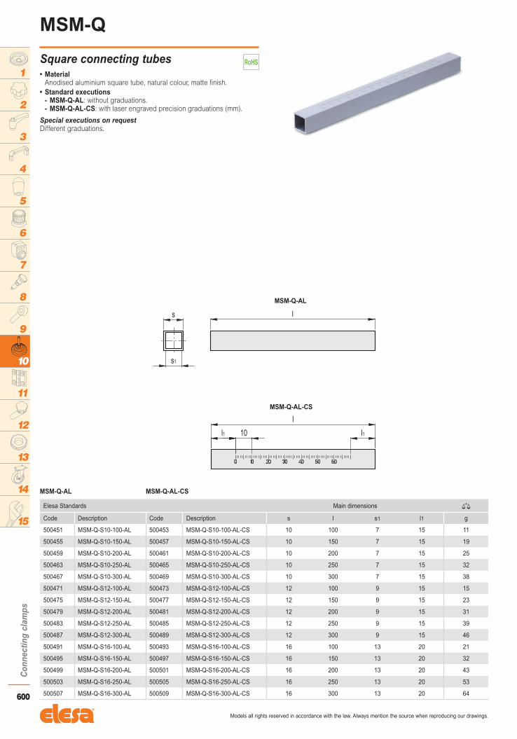
Special executions on requestDifferent graduations.
• MaterialAnodised aluminium square tube, natural colour, matte finish.
• Standard executions- MSM-Q-AL: without graduations. - MSM-Q-AL-CS: with laser engraved precision graduations (mm).
Square connecting tubes
MSM-Q
Elesa Standards Main dimensions �
Code Description Code Description s l s1 l1 g
500451 MSM-Q-S10-100-AL 500453 MSM-Q-S10-100-AL-CS 10 100 7 15 11
500455 MSM-Q-S10-150-AL 500457 MSM-Q-S10-150-AL-CS 10 150 7 15 19
500459 MSM-Q-S10-200-AL 500461 MSM-Q-S10-200-AL-CS 10 200 7 15 25
500463 MSM-Q-S10-250-AL 500465 MSM-Q-S10-250-AL-CS 10 250 7 15 32
500467 MSM-Q-S10-300-AL 500469 MSM-Q-S10-300-AL-CS 10 300 7 15 38
500471 MSM-Q-S12-100-AL 500473 MSM-Q-S12-100-AL-CS 12 100 9 15 15
500475 MSM-Q-S12-150-AL 500477 MSM-Q-S12-150-AL-CS 12 150 9 15 23
500479 MSM-Q-S12-200-AL 500481 MSM-Q-S12-200-AL-CS 12 200 9 15 31
500483 MSM-Q-S12-250-AL 500485 MSM-Q-S12-250-AL-CS 12 250 9 15 39
500487 MSM-Q-S12-300-AL 500489 MSM-Q-S12-300-AL-CS 12 300 9 15 46
500491 MSM-Q-S16-100-AL 500493 MSM-Q-S16-100-AL-CS 16 100 13 20 21
500495 MSM-Q-S16-150-AL 500497 MSM-Q-S16-150-AL-CS 16 150 13 20 32
500499 MSM-Q-S16-200-AL 500501 MSM-Q-S16-200-AL-CS 16 200 13 20 43
500503 MSM-Q-S16-250-AL 500505 MSM-Q-S16-250-AL-CS 16 250 13 20 53
500507 MSM-Q-S16-300-AL 500509 MSM-Q-S16-300-AL-CS 16 300 13 20 64
MSM-Q-AL MSM-Q-AL-CS

601
Con
nect
ing
clam
ps
Models all rights reserved in accordance with the law. Always mention the source when reproducing our drawings.
1
2
3
4
5
6
7
8
9
10
11
12
13
14
15
Special executions on requestDifferent graduations.
• MaterialAISI 304 stainless steel.
Bar for d = 8 and 10.
Tube for d = 12, 16 and 20.
• Standard executions- MSM-T-SST: without graduations.- MSM-T-SST-CS: with laser engraved precision graduations (mm).
Connecting tubes
MSM-T
Elesa Standards Main dimensions �
Code Description Code Description d l d1 l1 g
500551 MSM-T-D8-100-SST 500553 MSM-T-D8-100-SST-CS 8 100 - 15 39
500555 MSM-T-D8-150-SST 500557 MSM-T-D8-150-SST-CS 8 150 - 15 59
500559 MSM-T-D8-200-SST 500561 MSM-T-D8-200-SST-CS 8 200 - 15 78
500563 MSM-T-D8-250-SST 500565 MSM-T-D8-250-SST-CS 8 250 - 15 98
500567 MSM-T-D8-300-SST 500569 MSM-T-D8-300-SST-CS 8 300 - 15 118
500571 MSM-T-D10-100-SST 500573 MSM-T-D10-100-SST-CS 10 100 - 15 62
500575 MSM-T-D10-150-SST 500577 MSM-T-D10-150-SST-CS 10 150 - 15 100
500579 MSM-T-D10-200-SST 500581 MSM-T-D10-200-SST-CS 10 200 - 15 123
500583 MSM-T-D10-250-SST 500585 MSM-T-D10-250-SST-CS 10 250 - 15 154
500587 MSM-T-D10-300-SST 500589 MSM-T-D10-300-SST-CS 10 300 - 15 185
500591 MSM-T-D12-100-SST 500593 MSM-T-D12-100-SST-CS 12 100 9 15 37
500595 MSM-T-D12-150-SST 500597 MSM-T-D12-150-SST-CS 12 150 9 15 56
500599 MSM-T-D12-200-SST 500601 MSM-T-D12-200-SST-CS 12 200 9 15 74
500603 MSM-T-D12-250-SST 500605 MSM-T-D12-250-SST-CS 12 250 9 15 93
500607 MSM-T-D12-300-SST 500609 MSM-T-D12-300-SST-CS 12 300 9 15 112
500611 MSM-T-D16-100-SST 500613 MSM-T-D16-100-SST-CS 16 100 13 20 54
500615 MSM-T-D16-150-SST 500617 MSM-T-D16-150-SST-CS 16 150 13 20 82
500619 MSM-T-D16-200-SST 500621 MSM-T-D16-200-SST-CS 16 200 13 20 109
500623 MSM-T-D16-250-SST 500625 MSM-T-D16-250-SST-CS 16 250 13 20 137
500627 MSM-T-D16-300-SST 500629 MSM-T-D16-300-SST-CS 16 300 13 20 164
500631 MSM-T-D20-100-SST 500633 MSM-T-D20-100-SST-CS 20 100 16 25 85
500635 MSM-T-D20-150-SST 500637 MSM-T-D20-150-SST-CS 20 150 16 25 127
500639 MSM-T-D20-200-SST 500641 MSM-T-D20-200-SST-CS 20 200 16 25 170
500643 MSM-T-D20-250-SST 500645 MSM-T-D20-250-SST-CS 20 250 16 25 213
500647 MSM-T-D20-300-SST 500649 MSM-T-D20-300-SST-CS 20 300 16 25 256
MSM-T-SST MSM-T-SST-CS