Embed Size (px)
Citation preview
1
High Capacity Micropiles In Karst:
Challenges and Opportunities
RP Traylor1
AW Cadden, PE2
D A. Bruce, MASCE 3
Abstract
Extreme variations in ground conditions which categorize karstic limestone terraininevitably create challenges during design and installation of deep foundation systems. Forexample, the elevation of rock head may vary greatly over short distances, while forsubstantial depths below rock head, one may anticipate the presence of major solutionfeatures. Such features may be entirely open, or may be partially or completely filled withproducts of the limestone degradation. High capacity micropiles of the type described byFHWA (1997) have, for some years now, proved to be a technically and economicallyviable deep foundation system in such terrain. Frequently, they have been the onlyplausible solution. This adaptability is a result of the large variety of small diameterborehole drilling techniques which can be exploited to ensure penetration in suchconditions, and also the fact that micropiles transfer load by skin friction. The designimplication is that if certain thickness of “good” rock is encountered, then a certain pilecapacity can be guaranteed. There is therefore dramatically reduced risk of piles“punching through” into a solution feature as would occur in the case of an end-bearingpile. During the last several years, the authors have been involved in the design,construction and performance testing of high capacity micropiles in karst. This paperprovides an overview of these experiences and provides recommendations as to mostappropriate practice. Reference is made to several recent case histories.
Introduction
Most recent domestic studies describing micropiles relate to elements which aresmall diameter (≤12 inches), bored, grouted-in-place, and incorporate steel reinforcementwhich resists most of the load (FHWA, 1997; ASCE, 1997). However, depending on thesoil conditions and the performance requirements and levels of construction expertise, theconcept of a micropile may be broadened. For example, the thriving underpinning marketin Finland is largely served by jacked or percussed steel pipes installed to rock head andeither grouted in place or not (Lehtonen, 2001). The uniformity of the overburdenconditions and the predictability of bedrock elevations permit such straightforward andrepetitive methods to be used.
1 RP Traylor, GeoStructural Division Manager, Structural Preservation Systems, Inc.,Balto, MD
2 AW Cadden, Sr. Vice President, Schnabel Engineering and Associates, West Chester, PA3 DA Bruce, President, GeoSystems, L.P., Venetia, PA
2
However, when considering deep foundation construction in karstic terrain, thehighly variable and locally unpredictable nature of the ground invariably poses majorproblems. As designers become more aware of the advantages of the drilled and groutedmicropiles as typically used in North America, the use of such micropiles to solve deepfoundation problems in karst is becoming very common.
The purpose of this paper is to present an appreciation of the impact of karsticterrain on the design, construction and performance of micropiles. Details from recentcase histories are provided to illustrate the special measures which may have to be taken,and the pile performance data which may be anticipated.
Aspects of Karst Geology
The term "karst" refers to a type of hummocky terrain found in the Karst area of theformer republic of Yugoslavia. The area is underlain by carbonate bedrock that is prone tochemical weathering and solutioning and is characterized by sinkholes, caves, encloseddepressions, pinnacled bedrock, and other solution features. The term has beengeneralized to describe any area that has similar features. These areas are mainly underlainby carbonate bedrock such as limestone, dolomite, and marble but may also have gypsumor other types of rocks that are prone to the same types of solution or weathering features.
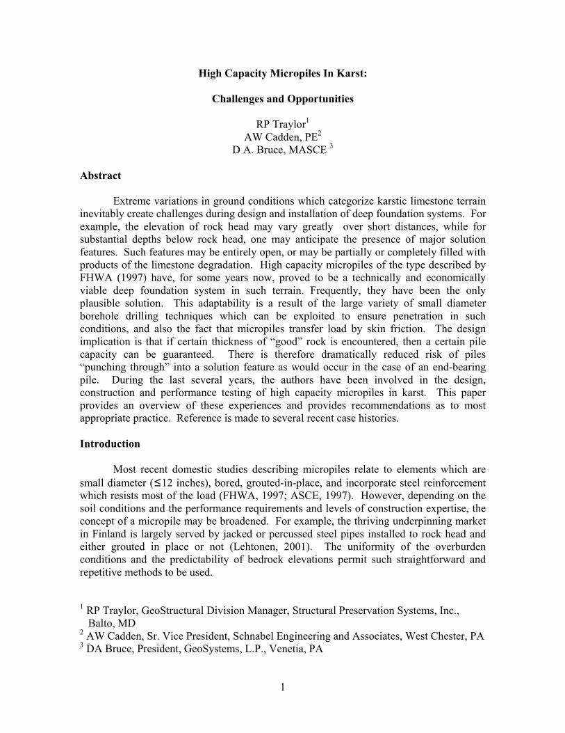
Karstic solution features are formed when water moves through interconnectedopenings in the rocks. Potentially weak or exploitable zones in the rock, such as beddingplanes, joints, fractures, and faults, where they are enlarged by the solvent action ofslightly acidic water. The solutioning process generally creates pinnacles, cutters, floatingboulders, and caverns within otherwise competent hard rock strata. Overburden soilsabove such cavities can collapse into the voids forming sinkholes. (Figure 1)
Figure 1. Progressive Development of Karst (Geyer, and Wilshusen,, 1982)
3
Downward migration, or subsurface erosion of soil into underlying openings inbedrock, can also occur as well as collapse of resulting cavities from constructionequipment loads and related vibrations, or new structural loads. If there is a substantialdecline in the water table, it may result in a loss of buoyant support and an increase in thegroundwater flow velocity. These can also induce sinkholes by promoting void collapseand movement of soil into solution cavities.
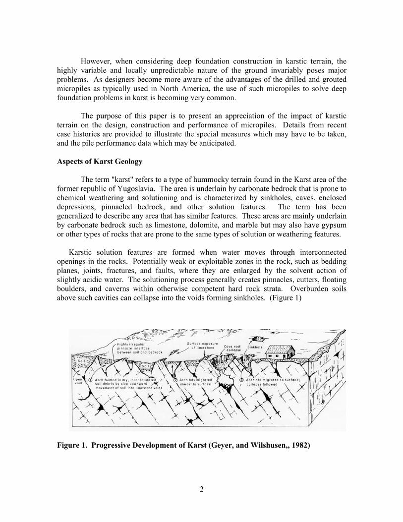
Karst comes in many forms and is found in many areas of the United States andaround the world. In areas such as eastern Pennsylvania, the limestone and dolomites ofthe Ridge and Valley and Piedmont, are of Ordovician and Cambrian age. These rockshave undergone extensive folding and faulting resulting in steeply dipping bedding planesand highly fractured rock. Marbles are encountered in northern Delaware. However, inareas such as western Pennsylvania and Ohio, the Pennsylvanian age carbonate rocks aremore flat lying and have undergone only minor geologic stresses. The carbonate materialsof Florida are somewhat different again, including softer and flat lying strata including,coquina, coral deposits and un-metamorphosed limestone and dolomite. The unconfinedcompressive strengths of these materials can vary from greater than 20,000 psi for theOrdovician limestone and Cambrian age marbles to less than 2000 psi for the ooliticlimestone of Florida, and even lower for the gypsums. In general, some form of nearsurface carbonate material has been reported to be present in about 15% of the UnitedStates. (Figure 2)
Completing a representative study of a site underlain by karst can be difficult andexpensive. An exploration consisting of borings conventionally spaced at about 100 ftcenters is very likely to miss many karst features and may not extend deep enough todetect potential problems in the rock mass. A thorough study of these sites is warrantedand should begin with research of regional conditions through the use of air photos,fracture trace studies, geologic mapping, remote sensing, historic mapping, localknowledge and site reconnaissance. This will provide a basis to develop a more sitespecific study which will be more likely to identify the true conditions.
Before test borings are drilled, additional indirect measurements can be made.Geophysical tools provide a means for indirectly measuring the potential variations acrossa site and identifying anomalous areas. Historically, tools such as ground penetratingradar, microgravity, shear wave, seismic reflection, seismic refraction, electromagnetic andspontaneous potential surveys have been used with varying degrees of success. Recentdevelopments in computerized data collection, instrument sensitivity and post-processinghave facilitated the use of methods such as Resistivity and Induced Polarization profilingwhich has proven to be very effective when performed, modeled and interpreted bycompetent and experienced personnel. (eg Bruce et al., 2001)(Dunscomb, 1999)
With an understanding of the regional geology and the potential site specificvariability, the proposed development of a site can be considered, including size,earthwork requirements and foundation loads, and stormwater management issues. Theinvasive site exploration can then include traditional test borings, insitu testing and augerprobes. Rock coring should also be performed in most cases to characterize the potential
4
variability of the rock, to confirm that the apparent surface of the rock is more than abolder or ledge, and to look for indications of voids. Additional exploration using airpercussion drilling techniques often provides cost-effective means of supplementingtraditional borings and gaining better site resolution of rock head variability.
The irregular conditions clearly can have a significant impact on construction inkarst areas. Structures ranging from residential homes to the Petronas Tower in Malaysiahave been constructed over karst. Figure 2 shows the location of metropolitan areasrelative to underlying karst conditions in North America. As the infrastructure in theseareas is repaired and expanded, treatment of the underlying conditions will pose significantdifficulties. For example, several recent transportation projects in eastern Pennsylvaniahave incurred millions of dollars in ground treatment costs associated with karst conditionsencountered during construction.
Figure 2. Engineering Aspects of karst, National Atlas, (WE Davies et al., USGS1984)
Application of Micropiles
Micropiles in karst are used to provide structural support mainly as foundations fornew structures, as underpinning of existing structures, and less frequently as part of aseismic retrofit where potentially liquefiable soils overly the bedrock. Regarding theunderpinning of existing structures, micropiles are used to repair or replace existingfoundations, to arrest or prevent movements, or simply to upgrade the existing foundationcapacity. They are typically installed to resist axial loads, usually compression, althoughseismic applications will also involve lateral and/or tensile loading. Micropiles in karst areinvariably designed as Case 1 (direct load carrying) and are typically Type A elements(FHWA, 1997), (Figure 3)
5
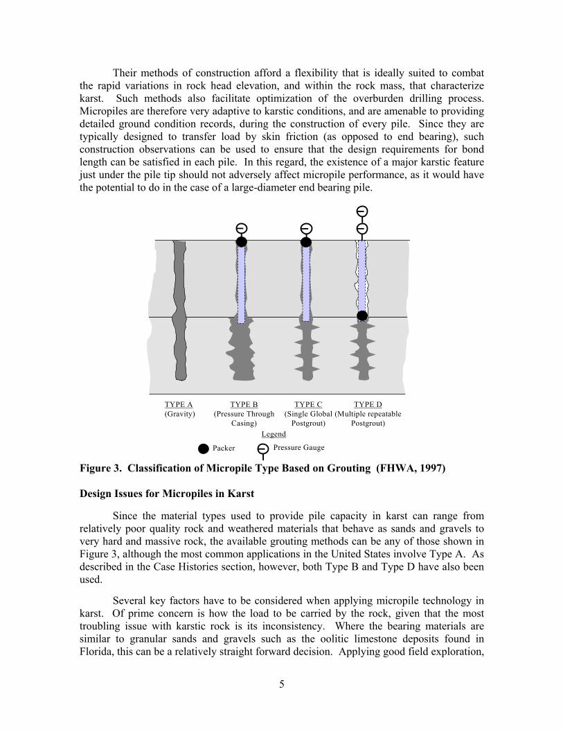
Their methods of construction afford a flexibility that is ideally suited to combatthe rapid variations in rock head elevation, and within the rock mass, that characterizekarst. Such methods also facilitate optimization of the overburden drilling process.Micropiles are therefore very adaptive to karstic conditions, and are amenable to providingdetailed ground condition records, during the construction of every pile. Since they aretypically designed to transfer load by skin friction (as opposed to end bearing), suchconstruction observations can be used to ensure that the design requirements for bondlength can be satisfied in each pile. In this regard, the existence of a major karstic featurejust under the pile tip should not adversely affect micropile performance, as it would havethe potential to do in the case of a large-diameter end bearing pile.
Figure 3. Classification of Micropile Type Based on Grouting (FHWA, 1997)
Design Issues for Micropiles in Karst
Since the material types used to provide pile capacity in karst can range fromrelatively poor quality rock and weathered materials that behave as sands and gravels tovery hard and massive rock, the available grouting methods can be any of those shown inFigure 3, although the most common applications in the United States involve Type A. Asdescribed in the Case Histories section, however, both Type B and Type D have also beenused.
Several key factors have to be considered when applying micropile technology inkarst. Of prime concern is how the load to be carried by the rock, given that the mosttroubling issue with karstic rock is its inconsistency. Where the bearing materials aresimilar to granular sands and gravels such as the oolitic limestone deposits found inFlorida, this can be a relatively straight forward decision. Applying good field exploration,
TYPE A(Gravity)
TYPE B(Pressure Through
Casing)
TYPE C(Single Global
Postgrout)
TYPE D(Multiple repeatable
Postgrout)
Packer Pressure Gauge
Legend
6
observation, knowledge of the geomorphology of the area and past experience, the bondzone location and condition of a pile can be determined. However, if the conditionsconsist of highly variable soil conditions over very hard rock, the rock is often the mostdesirable material to develop significant capacities. These rock masses are often highlyfractured and can contain voids, seams and caverns. The average, ultimate bond values ofType A piles in this massive hard rock have been shown to be in excess of 250 psi(Cadden, 2000). Thus, as with anchors in rock, bond lengths greater than about 3m rarelyproduce much increase in capacity. However, the elevation of the desirable rock forbonding is usually highly variable at a given site.
Several alternatives have been applied to accommodate these conditions. The mostdirect solution would involve drilling until 3 m of essentially massive rock is encountered.A more efficient pile would seek to consider the benefit of the discontinuous rock in someform. This is where the experience, sound engineering, and understanding of the localgeology are critical. With such knowledge, the consideration of discontinuous masses ofcompetent rock can be additive to reach the desired 3 m length. Great care must be appliedto establish the suitable definition of a segment of competent, acceptable rock. Thisdefinition will include the minimum allowable length of each segment, the permissiblelength of discontinuity between each segment, and the acceptable material within thisdiscontinuity.
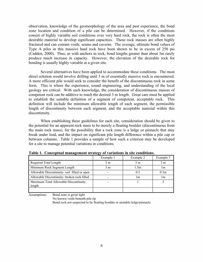
When establishing these guidelines for each site, consideration should be given tothe potential for an apparent rock mass to be merely a floating boulder (discontinuous fromthe main rock mass), for the possibility that a rock zone is a ledge or pinnacle that maybreak under load, and the impact on significant pile length difference within a pile cap orbetween columns. Table 1 provides a sample of how such a criterion may be developedfor a site to manage potential variations in conditions.
Table 1. Conceptual management strategy of variations in site conditions.Example 1 Example 2 Example 3
Required Total Length 3 m 3 m 3 mMinimum Rock Segment Length 3 m 1.5m 1mAllowable Discontinuity- soil filled or open - 0.5 0.3mAllowable Discontinuity- broken rock filled - 1m 1mMaximum Total Allowable Discontinuitylength
- 1 2
Assumptions: Bond zone is grout tightNo known voids beneath pile tipBond rock not suspected to be floating boulder or unstable ledge/pinnacle
7
The type of reinforcing used for the pile is variable and is often limited by thedrilling methods utilized. Both pipe and central bars are common types of reinforcement.Each of these can be used exclusively or the two in combination. With all micropiles, themethod of installation must ensure that the reinforcement throughout the bond zone isadequately embedded in grout. This can be achieved in a stable hole through tremiegrouting. However, in more difficult conditions, care must be taken to ensure that thegrout fills the bond zone completely and remains in place as the reinforcement is placed,and before setting.
Grouting of the pile is most often achieved with a cement based grout composed ofwater and Type I or III Portland cement having a water cement ratio (w:c) of about 0.45 to0.5 by weight. Often, admixtures such as fluidizers and retarders are utilized to facilitatepumping. Accelerators or clays are not recommended due to potential corrosion and lossof friction associated with these materials. These grouts have little difficulty achievingcompressive strengths of over 4000 psi. Often the inconsistencies in karst geology willresult in grout loss from the drill hole. Therefore, for economic reasons, alternative groutsincluding sand and other fillers can be used to fill voids and stabilize the pile hole. Thefiller grout is generally not suitable for load transfer and the bond zone must be thoroughlycleaned after drilling and before final grouting is performed.
Where very soft soils or voids are penetrated, or where there is a future potentialpossibility for a sinkhole to develop adjacent to a pile, structural buckling of the pile maybe a consideration. Questions also arise about buckling potential where the hole drilled isslightly larger than the casing used for reinforcement of the pile and the grout coverage inthe annulus space is not assured. As presented in Bjerrum (1957), only very limitedstrength within the soil is required to result in the pile being supported continuously alongits length. In materials such as peat, unconsolidated soft clays and loose silt where theelastic moduli is less than about 70 psi, buckling should be evaluated. Thus, nearly anysoil present around the pile, including material that will squeeze to fill the annulus space isconsidered adequate for lateral support. Only where there is reason to believe that the pilewill penetrate a void which is not filled with grout during construction, is it necessary todesign for special buckling considerations. For the long-term condition where futuresinkholes are likely, redundancy in the pile system or other advanced ground treatmentmust be considered for the site.
Influence of one pile on another is generally not considered to be an issue wherethe center to center spacing exceeds three times the pile diameter. This has been shown tobe reasonable for micropiles as well. However, given the extremely high capacities thatcan be achieved with micropiles in rock, the group effect and the overall rock massstrength must be considered.
Given the highly variable conditions typical of karstic bedrock, the lengths of themicropiles above the bond zone may vary significantly. Often these lengths can bethrough overburden soils which will provide little if any resistance to the vertical loads.As such, elastic movement of adjacent or nearby piles above the bond zones can varydramatically in service. Load testing of adjacent piles at the Exton Mall Project in
8
Pennsylvania (Cadden et al., 2000) depicted this impact: tests of two adjacent piles, whichvaried in lengths from 21.5 to 30.5 m, resulted in nearly 10 mm in differential movementof the piles at design load and 25 mm at test load. This difference in stiffness in a pile capwill result in redistribution of loads to the pile and rotation of the cap element. Careshould be exercised to evaluate these conditions when encountered in a foundation elementor to design the entire foundation system to account for such anomalies by tyingfoundation elements together to limit potential rotation. Alternatively, stiffening of longerpiles through the placement of additional steel in the element can be used to create moreuniform movement performance.
Construction
Micropiles are constructed in essentially three steps: (a) drill hole to pile tipelevation, (b) install reinforcement, and (c) install grout. Karstic conditions offerchallenges to all three steps, motivating micropile contractors to use the most efficientcombination of procedures to optimize installation. For instance, using the drill casing orrod as the steel reinforcement eliminates one of three steps and may reduce labor cost, butincreases material cost. Does the faster production rate offset the increase in other costssufficient to use the method? Can the thread design of the drill string or casing withstandthe loads to be placed on the pile reinforcement? While each site is unique, and in fact,each hole can be unique and essentially a new job, certain methods have proven effectivein recent years. These commonalties are now reviewed.
Drilling From an engineering viewpoint, the drilling method selected for a particularproject should be dictated by the rock and overburden conditions at site. However, drillingtechniques for rock and overburden are commonly driven by the type of equipment andhardware or “tooling” available to the contractor. Since the equipment and the tooling arevery expensive, contractors are reluctant to change tooling systems from job to job.Consequently, a contractor will prefer a particular method over others simply because it isin the contractor’s yard and within his field of experience.
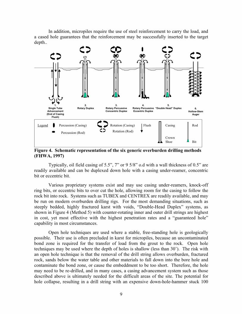
Drilling overburden is accomplished through the use of six methods and drillingrock or weathered rock by three (FHWA, 1997) (Figure 4). Drilling in karst ensures thateach pile location will encounter overburden, rock, and weathered rock and the conditionswill be encountered at highly variable elevations, with the potential for voids at greatdepth. All of the drilling methods, with the exception of “Single Tube Advancement”(Method 1) are effected by the ability of the driller to maintain an open path for drillcuttings to escape the bore hole. If the cuttings are allowed to drop on top of the bitassembly at the cutting face, the drill string may become locked in the hole, or at the veryleast, drill production will be dramatically reduced. Since karst is characterized byfractured rock, weathered seams and voids, there is great potential to lose the air andcuttings prior to reaching the top of the hole. Therefore, the most effective drill toolingsystems are “Duplex” drilling systems, i.e. those that advance the casing down hole withthe drill string as depicted in Figure 4 (Methods 2, 3, 4 and 5), thus protecting the holestability by mechanical means.
9
In addition, micropiles require the use of steel reinforcement to carry the load, anda cased hole guarantees that the reinforcement may be successfully inserted to the targetdepth..
Figure 4. Schematic representation of the six generic overburden drilling methods(FHWA, 1997)
Typically, oil field casing of 5.5”, 7” or 9 5/8” o.d with a wall thickness of 0.5” arereadily available and can be duplexed down hole with a casing under-reamer, concentricbit or eccentric bit.
Various proprietary systems exist and may use casing under-reamers, knock-offring bits, or eccentric bits to over cut the hole, allowing room for the casing to follow therock bit into rock. Systems such as TUBEX and CENTREX are readily available, and maybe run on modern overburden drilling rigs. For the most demanding situations, such assteeply bedded, highly fractured karst with voids, “Double-Head Duplex” systems, asshown in Figure 4 (Method 5) with counter-rotating inner and outer drill strings are highestin cost, yet most effective with the highest penetration rates and a “guaranteed hole”capability in most circumstances.
Open hole techniques are used where a stable, free-standing hole is geologicallypossible. Their use is often precluded in karst for micropiles, because an uncontaminatedbond zone is required for the transfer of load from the grout to the rock. Open holetechniques may be used where the depth of holes is shallow (less than 30’). The risk withan open hole technique is that the removal of the drill string allows overburden, fracturedrock, sands below the water table and other materials to fall down into the bore hole andcontaminate the bond zone, or cause the embeddment to be too short. Therefore, the holemay need to be re-drilled, and in many cases, a casing advancement system such as thosedescribed above is ultimately needed for the difficult areas of the site. The potential forhole collapse, resulting in a drill string with an expensive down-hole-hammer stuck 100
Legend Percussion (Casing)
Percussion (Rod)
Rotation (Casing)
Rotation (Rod)
Flush Casing
CrownShoe
Rod
Bit
1.Single Tube
Advancement(End of Casing
Flush)
2.Rotary Duplex
3.Rotary PercussiveConcentric Duplex
4.Rotary PercussiveEccentric Duplex
5.“Double Head” Duplex 6.
Hollow-StemAuger
10
feet in the ground implies that the drill rig selected should have sufficient torque andretract force to extract the string. Water injection seems to aid initial hole stability andlubrication, thus reducing the potential for a lost drill string.
Single tube advancement using air or water flush is not recommended because theflushing medium may further unravel the karst structure by flushing clay from seams, orinflating the overburden. Continuous-flight auger sections (Method 6), as well aspercussive single tube advance (Method 1)with a lost bit are not recommended and cannotdrill rock efficiently.
Drilling in karst may produce large amounts of the clayey residual weatheredcarbonate limestone or dolomite. This red- brown clay will be wet and quite slick and ifleft unmanaged, will render a site impassable. Spoils removal is necessary for themanagement of a clean site. When drilling indoors, duplex drilling systems areadvantageous because a spoils collar may be installed on the rig, capturing the spoils anddiverting them out of the structure through a hose.
As noted above, micropile design in karst requires an awareness of relative pilelengths within a pile cap. The drilling sequence of piles must also be carefully planned sothat ungrouted or uncured grouted pile bond zones are not compromised during the drillingof adjacent or nearby piles. In general, a distance of 15 feet is sufficient to reduce the riskof interconnection of drilling air between pile locations. However, in karst conditions,drilling air may travel great distances due to open karst features. On karst sites, carefulobservation of drilling processes on a hole by hole basis is the best quality control method.When drilling through or near existing foundation elements, the flushing air or water mayundermine the footing or pile cap. In these situations, duplex drilling, again, provides thebest risk management, as most air and cuttings are diverted to the surface through theinternal flush between the inner and outer drill string. A simple method that may proveefficient in this case is to rotate a disposable casing to suitable depth, allowing subsequentdrill cuttings to return directly to the surface.
Grouting As noted above, the grouting process defines the type, and often thecapacity of the micropile. The grouting competency of the contractor may, above all else,be the most critical variable in the performance of a micropile. The reinforcement steel,hole dimension, grout strength and pile design can be measured quantitatively, butgrouting is a process, and a process can only be evaluated subjectively.
Micropile grouting equipment consists at a minimum of a colloidal high speed,high shear mixer, holding tank with agitation, grout pump capable of reaching pressures of300 psi, pressure gauges, recirculation lines, qa/qc equipment and log books. The colloidalmixer is a high-shear grout plant that is capable of rapidly mixing neat cement based groutin a few minutes, with a thorough wetting of the individual cement grains. A thoroughwetting allows a low water-cement ratio grout to be pumped easily through the grout linesthat run from the plant to the pile. Without a colloidal plant, clumps of cement will clingtogether, clogging injection lines, and ultimately yielding a lower strength grout, becausesignificant amounts of the cement grains are not hydrated. Following a thorough mixing,
11
the grout must be stored in an agitation tank with agitation blades that constantly stir themixed grout, prolonging separation of the cement from the mix water. With properadmixtures, grout life may be extended easily to a working time of 6 hours, and in somecases, may be suspended indefinitely until the reaction is re-initiated on demand. A MarshCone simplifies optimization of the grout mix design with respect to retarders andfluidifiers. A Marsh Cone time of 11 – 14 seconds is typically considered ideal forpumping into micropile packer systems.
Grout strength is typically required to be measured at 7 and 28 days, and to reachover 4000 psi. Since the grout for micropiles is essentially neat cement and water, thespecific gravity, measured at the time of mixing and injection, can be extrapolated to thestrength at cure. For instance, a grout mix with a water cement ratio of 0.45, with anultimate strength at 7 days of 4000 psi, will have a specific gravity of approximately 1.89.If the density of the grout is less than this figure, the batch may be discarded, and a newbatch mixed for testing and injection.
Grout pumps are typically progressive cavity style pumps, such as Moyno® pumpsbecause the flow rate and pressures remain nearly constant during recirculation andinjection phases. Grout injection pressures at or below 100 psi for Type B piles is typical,yet Type D piles may require injection pressures peaking at over 1000 psi for re-groutingthrough initially set primary grout. This will require piston or ram pumps (Muller andBruce, 2000) Recirculation lines and injection manifolds allow the grout to remain inmotion during non-injection sequences, preserving the fluid characteristics and stability ofthe grout. If the grout is allowed to stand still in the hoses running from the plant to thepile for an extended period of time, the grout will stiffen and begin to approach an initialset. Re-agitation of the grout will cause a drop in final strengths at cure.
Installation Records The micropile contractor must keep accurate and contemporaneouslogs showing detailed installation information. Boring logs are used for planning the pileinstallation, but in karst conditions, rock head may vary greatly within a few feet of theboring. In karst, it is concievable that each pile will be unique in overall length, un-bondedlength, depth to rock head and sequencing of adequate bearing stratum, as shown in Table2. The pile installation log is the only record of the verification of the pile designdimensions and compositions having been achieved. The pile installation log is alsogenerates the pay items for the project, such as drilled footage in soil as well as rock, andamount of grout consumed. The contractor must be able to verify through his logs that thedesign requirement of a given amount of rock has been encountered in order to substantiatethat a pile of the design capacity has been installed.
Illustrative Case histories
Warren County, NJ (Bruce, 1989)
Background: conventional H piles could not be installed as foundations for a bridge piernear the Delaware River. A total of 24 micropiles each of 100 tons working load weredesigned, which proved more economic than an alternate based on six large diameter end
12
bearing (36-inch) caissons . Also a load test was foreseen, which would give the Ownercomfort that the individual micropile capacity could be attained (in skin friction).
Site and Ground Conditions: the bedrock was a Cambro-Ordovician dolomitic limestonereferred to locally as the Allentown Limestone. It proved to be moderately to highlyfissured, cherty, and very susceptible to karstic weathering. Major clay filled beds wereintersected even over 100 feet below the surface, for example, 50 feet of soft brown siltyclay below 106 feet at the location of pile 24. Dipping 55° to the southeast, the rock massproved highly variable laterally and vertically.
Geotechnical Issues: design of the bond length was based on a maximum averagerock/grout bond at working load of 50 psi, and so a bond length of 8½-inch-diameter and15’ feet long in competent rock was chosen for these Type 1A piles. Recognizing that therock was likely to be very variable, provision was made to allow the 15-foot bond zone tonot necessarily be continuous. In most piles this was subject to the following restrictions:
• The lower part of the zone was to contain at least 10 feet of continuous soundrock.
• Soft interbeds were to be less than 3 feet thick.• A zone of acceptable load-bearing rock was to be at least 5 feet thick.• Regrouting and redrilling of interbeds within the overall bond zone was to be
undertaken if required.
However, certain piles were judged especially critical structurally, (mainly on the footingperimeter) and were required to have a 15 foot continuous bond zone.
Construction Issues: individual pile lengths varied from 44 to 200 feet across the 21-foot x17-foot site. Compared to the allowable deviation of 2°, no pile exceeded 78% of thisfigure, while the overall average was 0.8°. Throughout, the very adverse conditions posedserious drilling problems, resolved only by repeated pregrouting and redrilling ( At thetime of construction, no experience existed in the use of a percussive duplex method, suchas Tubex, to stabilize such conditions). Poor or voided rock was consistently found belowthe anticipated elevation of the alternative caissons, further justifying the use of micropiles.Overall, the total drilled length of 1920 linear feet corresponded with the total foreseenquantity of 1710 linear feet. Variations from 43 feet less to 30 feet more with respect toforeseen were recorded on individual piles, highlighting the variability of the rock.Overall, a volume of grout equivalent to four times the nominal hole volume drilled wasinjected. Much of this was consumed during pregrouting operations. The level ofmaximum takes corresponded with groundwater level.
Performance/Testing: a special test pile, 30 feet long with a 5.33-foot-long bond zone wassubjected to a static compression load test to just over twice working load. Procedureswere taken to isolate the bond zone and prevent end bearing. At Test Load, the ElasticRatio (Bruce et.al., 1993) analysis configured that only the upper 25 feet of the pile wasacting as if debonded, i.e., that practically no debonding had occurred in the rock socket,even at nominal average grout/rock and grout/steel bonds of 304 and 250 psi respectively.
13
Creep at Test Load was 0.011 inch in 60 minutes. Testing to failure of the steel pipereinforcement was then undertaken (224 tons) without apparent geotechnical failureoccurring.
Overall, the bridge has been completed since the late 1980s and the performance of themicropile supported pier has proved totally satisfactory.
San Juan, PR (Zelenko et al., 1998)
Background: the U.S. Post Office and Courthouse building in Old San Juan was builtbetween 1914 and 1940 on driven steel and timber piles. Concerns about the potential forliquefaction of the underlying sands led to a major seismic retrofit, which included the useof 217 micropiles, each with a working load of 60 tons compression, 40 tons tension, and 5tons in lateral capacity at a maximum allowable deflection of 0.5 inch.
Site and Ground Conditions: underlying 8 to 10 feet of variable fills and about 25 feet offine to coarse sands, was the weathered limestone bedrock. This stratum had a variablerock head elevation (varying by about 15 feet across the site), and a very variableconsistency (N = 11 to > 100), ranging from soft limestone to residual silts and clays. Themicropiles were all located inside the building, where access was often severely limitedand work was conducted in low headroom conditions. During construction, a number ofspecific challenges were faced, including:
• Simultaneous overhead demolition and site clearance.• Presence of an old basalt fortification wall dating from the 1600s.• Presence of numerous other drilling obstructions, such as existing piles, pile caps,
masonry footings, and remains of prior structures (none accurately recorded inavailable drawings).
• Water rationing and high ambient air temperatures.
These challenges were overcome by exploiting the flexibility afforded by judiciousmicropile design, and the quick responsiveness of the construction methodologies.
Geotechnical Issues: the drill casing (9½-inch o.d.) had to be embedded at least 3 feet intothe limestone, but not less than 25 feet below the existing floor slab. It was also requiredto extend the bond zone a further 14 feet into the rock, and to have a minimum diameter of8 inches.
Construction Issues: in addition to the challenges listed above, the instability of the bondzone after drilling, plus the high ambient temperatures, led to each hole being initiallytremie grouted through the drill rods, prior to their removal, with a retarded, fluid neatcement grout, colloidally mixed. Following insertion of the core steel reinforcement, thebond zone was then pressure grouted to promote enhanced bond capacity in the weak,weathered limestone (Type 1B pile).
Performance/Testing: four load tests were conducted to various acceptance criteria. Thefirst pile installed was selected for compression testing and had experienced constructionproblems resulting in a bond zone only about 11 feet long. The first loading of 200%DL(120 tons) provided a permanent movement of 2.056 inches which was not acceptable.
14
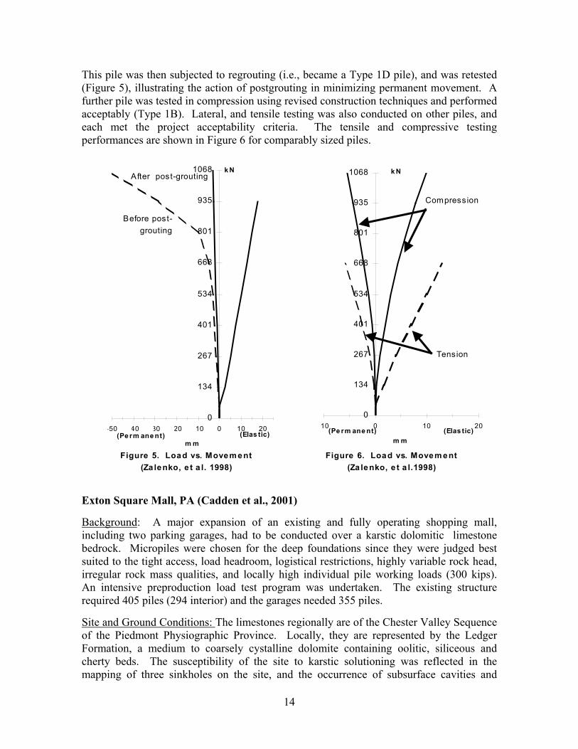
This pile was then subjected to regrouting (i.e., became a Type 1D pile), and was retested(Figure 5), illustrating the action of postgrouting in minimizing permanent movement. Afurther pile was tested in compression using revised construction techniques and performedacceptably (Type 1B). Lateral, and tensile testing was also conducted on other piles, andeach met the project acceptability criteria. The tensile and compressive testingperformances are shown in Figure 6 for comparably sized piles.
Exton Square Mall, PA (Cadden et al., 2001)
Background: A major expansion of an existing and fully operating shopping mall,including two parking garages, had to be conducted over a karstic dolomitic limestonebedrock. Micropiles were chosen for the deep foundations since they were judged bestsuited to the tight access, load headroom, logistical restrictions, highly variable rock head,irregular rock mass qualities, and locally high individual pile working loads (300 kips).An intensive preproduction load test program was undertaken. The existing structurerequired 405 piles (294 interior) and the garages needed 355 piles.
Site and Ground Conditions: The limestones regionally are of the Chester Valley Sequenceof the Piedmont Physiographic Province. Locally, they are represented by the LedgerFormation, a medium to coarsely cystalline dolomite containing oolitic, siliceous andcherty beds. The susceptibility of the site to karstic solutioning was reflected in themapping of three sinkholes on the site, and the occurrence of subsurface cavities and
Figure 5. Load vs. Movement (Za lenko, e t a l. 1998)
0
134
267
401
534
668
801
935
1068
-50 -40 -30 -20 -10 0 10 20
m m
k N
Before post-grouting
After post-grouting
(Pe rm ane nt) (Elas tic)
Figure 6. Load vs. Movem ent (Za lenko, e t a l.1998)
0
134
267
401
534
668
801
935
1068
-10 0 10 20
m m
k N
(Pe rm ane nt) (Elas tic)
Tension
Compression
15
pinnacles locally. Furthermore, a limestone quarry had previously been located on thewest side of the site, and was now backfilled to a depth of 27 feet. Typically overburdenconsisted of alluvial deposits (6 to 14 feet) overlying residual clayey soils to depths of upto 81 feet.
Geotechnical Issues: The bond zone was required to comprise 10 feet of competent rockand a diameter of 7½ to 8½ inches. Even the better quality rock was noted to havesignificant fissuring, giving the potential for grout loss from the bond zone.
Construction Issues: Both Type 1A and 1D micropiles were experimented with during theconstruction optimization phase. The piles for the existing structure varied from 20 to 150feet (average 34 feet) below existing slab, while the piles for the garages varied from 25 to180 feet (average 43 feet). The conceptual advantage of the Type 1D pile (whereinregrouting sleeves were installed on the full length 7-inch-diameter core reinforcing pipe)was that pregrouting and redrilling could be eliminated and the integrity of the groutaround the bond zone could be verified by postgrouting. During drilling of some test piles,running sand conditions were encountered below the water table which appeared to packaround the sleeved reinforcement pipe so preventing routine postgrouting beingaccomplished. Such difficulties, rendered the simple Type 1A approach with (often,repeated) pregrouting and redrilling the more practical and cost effective option on thisparticular site, even though load testing confirmed the ability of the Type 1D to satisfydesign requirements.
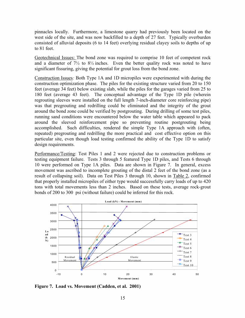
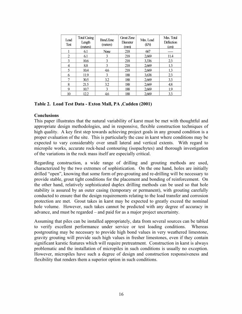
Performance/Testing: Test Piles 1 and 2 were rejected due to construction problems ortesting equipment failure. Tests 3 through 5 featured Type 1D piles, and Tests 6 through10 were performed on Type 1A piles. Data are shown in Figure 7. In general, excessmovement was ascribed to incomplete grouting of the distal 2 feet of the bond zone (as aresult of collapsing soil). Data on Test Piles 3 through 10, shown in Table 2, confirmedthat properly installed micropiles of either type would successfully carry loads of up to 420tons with total movements less than 2 inches. Based on these tests, average rock-groutbonds of 200 to 300 psi (without failure) could be inferred for this rock.
Load (kN) - M ovement (mm)
0
500
1000
1500
2000
2500
3000
3500
4000
-10 0 10 20 30 40 50M ovement (mm)
Load(kN)
Test 3Test 4Test 5Test 6Test 7Test 8Test 9Test 10
ResidualM ovement
ElasticM ovement
Figure 7. Load vs. Movement (Cadden, et al. 2001)
16
Load Test DataLoadTest
Total CasingLength(meters)
Bond Zone(meters)
Grout ZoneDiameter
(mm)
Max. Load(kN)
Max. TotalDeflection
(cm)1 6.1 None 218 667 -----2 6.1 3 218 2,669 11.43 10.6 3 218 3,336 2.34 8.8 3 218 2,669 1.35 10.4 4.6 218 2,669 1.36 11.9 3 188 3,638 2.37 30.5 3.2 188 2,669 3.38 21.5 3.2 188 2,669 4.89 10.7 3 188 2,669 1.910 12.2 4.6 188 2,669 3.3
Table 2. Load Test Data - Exton Mall, PA ,Cadden (2001)
ConclusionsThis paper illustrates that the natural variability of karst must be met with thoughtful andappropriate design methodologies, and in responsive, flexible construction techniques ofhigh quality. A key first step towards achieving project goals in any ground condition is aproper evaluation of the site. This is particularly the case in karst where conditions may beexpected to vary considerably over small lateral and vertical extents. With regard tomicropile works, accurate rock-head contouring (isopachytes) and thorough investigationof the variations in the rock mass itself are especially critical.
Regarding construction, a wide range of drilling and grouting methods are used,characterized by the two extremes of sophistication. On the one hand, holes are initiallydrilled “open”, knowing that some form of pre-grouting and re-drilling will be necessary toprovide stable, grout tight conditions for the placement and bonding of reinforcement. Onthe other hand, relatively sophisticated duplex drilling methods can be used so that holestability is assured by an outer casing (temporary or permanent), with grouting carefullyconducted to ensure that the design requirements relating to the load transfer and corrosionprotection are met. Grout takes in karst may be expected to greatly exceed the nominalhole volume. However, such takes cannot be predicted with any degree of accuracy inadvance, and must be regarded – and paid for as a major project uncertainty.
Assuming that piles can be installed appropriately, data from several sources can be tabledto verify excellent performance under service or test loading conditions. Whereaspostgrouting may be necessary to provide high bond values in very weathered limestone,gravity grouting will provide such high values in fresher limestones, even if they containsignificant karstic features which will require pretreatment. Construction in karst is alwaysproblematic and the installation of micropiles in such conditions is usually no exception.However, micropiles have such a degree of design and construction responsiveness andflexibility that renders them a superior option in such conditions.
17
References
ASCE (1997). Ground Improvement, Reinforcement, and Treatment: Developments 1987-1997,Chapter 26 on Micropiles, , Geotechnical Special Publication No. 69 Ed. by V.R. Schaefer, ASCE,pp. 151-175
Bjerrum (1957). Norwegian Experiences With Steel Piles to Rock, Geotechnique, Volume vii, No.2, 1957
Bruce, D.A. (1988, 1989). “Aspects of Minipiling Practice in the United States” GroundEngineering 21 (8) pp. 20-33 and 22 (1) pp. 35-39
Bruce D.A, Traylor RP, and Lolcama J (2001). The sealing of a massive water flow throughKarstic Limestone. Geo-Odyssey 2001, Proceedings ASCE Special Conference, Blacksburg, VA,June, 15 pp
Cadden A.W.,.Bruce, D.A. and Ciampitti L. M. (2001) “Micropiles in Karst: A Case History ofDifficulties and Success”. Geo-Odyssey 2001, Proceedings ASCE Special Conference, Blackburg,VA, June, 12 pp.
Dunscomb, Mark H. and Rehwoldt, 1999, Two-Dimensional Resistivity Profiling, GeophysicalWeapon of Choice In Karst Terrain for Engineering Applications, Proceedings From the 7th
Multidisciplinary Conference on Sinkholes and the Engineering and Environmental Impacts onKarst, Harrisburg, PA
FHWA (2000). “Micropile Design and Construction Guidelines” Publication No. FHWA-SA-97-070
FHWA (1997). “Drilled and Grouted Micropiles: State of Practice Review, Volumes I, II, III, IV”Prepared for the Federal Highway Administration, Publication Nos. FHWA-RD-96-016, -017, -018, -019, July. Authors: D. A. Bruce and I. Juran
Geyer, A.R., and Wilshusen, J.P., (1982), Engineering Characteristics of the Rocks ofPennsylvania, Environmental Geology Report 1, Department of Environmental Resources, Bureauof Topographic and Geologic Survey, Harrisburg, PA.
Lehtonen, J (2001). Shaft and Bearing Micropiles, Liceutiate Thesis, Tampere University ofTechnology, Finland, May, 203 pp.
Müller, R., and DABruce, (2000). “Equipment for Cement Grouting: An Overview.” Advances inGrouting and Ground Modification, Proceedings of Sessions of GeoDenver 2000, AmericanSociety of Civil Engineers, Denver, CO, August 5-8, Geotechnical Special Publication No. 104,Eds. R.J. Krizek and K. Sharp, pp 155-172.
WE Davies et al., USGS, National Atlas, Engineering Aspects of karst, (1984)
Zalenko, B.H., D. A. Bruce, D. A. Schoenwolf, and R.P. Traylor, (1998). “Micropile Applicationfor Seismic Retrofit Preserves Historic Structure in Old San Juan, Puerto Rico.” Grouts andGrouting: A Potpourri of Projects. Proceedings of Sessions of Geo-Congress 98, American Society of Civil Engineers, Geotechnical Special Publication No. 80, Boston, MA, October 18-21,pp. 43-62.