Embed Size (px)
Citation preview
From Design to Code: An Educational ApproachCandice Eckert∗, Brian Cham∗, Jing Sun† and Gillian Dobbie†
∗Department of Electrical and Computer Engineering†Department of Computer Science
The University of Auckland, New ZealandEmails: ∗{ceck002, bcha899}@aucklanduni.ac.nz, †{jing, gill}@cs.auckland.ac.nz
Abstract—Model Driven Engineering (MDE), despite havingmany advantages, is often overlooked by programmers due tolack of proper understanding and training in the matter. Thispaper investigates the advantages and disadvantages of MDE andlooks at research results showing the adoption rates of designmodels. In light of the findings, an educational tool, namelyLorini, was developed to provide automated code generation fromthe design models. The implemented tool consists in a plug-in forthe Astah framework aimed at teaching Java programming tostudents through UML diagrams. It features instantaneous codegeneration from three types of UML diagrams, code-diagrammatching, a feedback panel for error displays and on-the-flycompilation and execution of the resulting program. Evaluationof the tool indicated it to be successful with unique educationalfeatures and intuitive to use.
I. INTRODUCTION
The development of a software product includes manysteps such as requirement analysis, design, coding and testing.The design phase usually involves formal design models. Amore efficient alternative to manual coding is automated codegeneration from design models. This approach is known asModel Driven Engineering (MDE). The main advantages ofMDE are its efficiency in terms of development time[1] andthe reduction of human errors. This last property plays an im-portant role in real-time embedded systems, where the slightestmistake could lead to lethal consequences[2]. However, thestructure of auto-generated code is more complex than manualcode, making it harder to understand and re-use[3]. It isalso less efficient in terms of number of calls per executablestatement, number of executable statements, and time takenby stack allocation/deallocation[1].
The main issue regarding MDE remains the low adoptionrate. Only 11% of programmers often use formal designmodels, others using it scarcely, for communication purposesonly, or not at all[4]. This is mostly due to a lack of under-standing and training in the matter. An experiment conductedon a software design class showed that most students didnot use MDE before the course, and 70% of them foundMDE to be useful in order to understand software design[5].By combining these research results, the emerging factorseems to be the lack of educational tools for programmers tolearn formal design modelling. This has the unfortunate effect
DOI reference number: 10.18293/SEKE2016-007
of reducing the adoption rate of MDE, even though manyimprovements could be introduced by using design models.
Giving a new direction to the research, it was found thatteaching modelling before programming is feasible and evenbeneficial, considering that modelling is applicable to differentdisciplines and can favour a more structured learning[6]. It issuspected that complex object oriented concepts could be moreeasily grasped by students if they were introduced throughdesign models. As a consequence of these findings, we decidedto develop an educational tool for students to learn objectoriented programming starting from formal design models,specifically learning Java from UML. An overview blockdiagram of the implemented tool is shown in Figure 1.
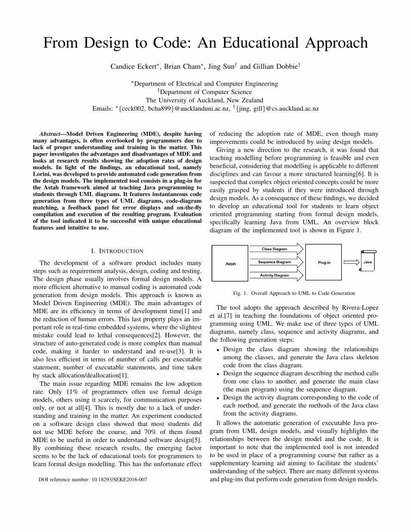
Fig. 1. Overall Approach to UML to Code Generation
The tool adopts the approach described by Rivera-Lopezet al.[7] in teaching the foundations of object oriented pro-gramming using UML. We make use of three types of UMLdiagrams, namely class, sequence and activity diagrams, andthe following generation steps:
• Design the class diagram showing the relationshipsamong the classes, and generate the Java class skeletoncode from the class diagram.
• Design the sequence diagram describing the method callsfrom one class to another, and generate the main class(the main program) using the sequence diagram.
• Design the activity diagram corresponding to the code ofeach method, and generate the methods of the Java classfrom the activity diagrams.
It allows the automatic generation of executable Java pro-gram from UML design models, and visually highlights therelationships between the design model and the code. It isimportant to note that the implemented tool is not intendedto be used in place of a programming course but rather as asupplementary learning aid aiming to facilitate the students’understanding of the subject. There are many different systemsand plug-ins that perform code generation from design models.

After a brief analysis of thirty-five of them, a number of free,open-source tools were extracted and investigated in moredepth. Some tools were found to be too complicated to use ordifficult to install due to lack of documentations. With carefulconsideration, the Astah framework was elected as the bestoption. Its interface is user-friendly and easy to understand forintuitive users. A clear set of APIs is available, making it easilyextendible. Moreover a free licence is dispensed to students,thus facilitating both the design and evaluation processes.Astah is available on Windows, Linux and Mac OS X, andthe plug-ins are easy to install. The tools used were EclipseIDE for code development and a Github repository for versioncontrol, helping with collaboration and synchronization. Theoutcome of the project was an interactive plug-in for the Astahmodelling framework.
The rest of the paper was structured as follows. SectionII discusses the findings of related research in the field,including surveys and existing solutions. In section III, weoutline the objectives and technical decisions behind the plug-in to explain the rationale of the project. Section IV describesthe implementation details of the plug-in to explain how itwas developed. In section V, we list the criteria and conductevaluations to assess the success of the plug-in. Finally, sectionVI concludes the paper and outlines the future work.
II. LITERATURE REVIEW
The development method of automatically generating soft-ware from design models is referred to as Model-DrivenEngineering. In this practice, the design of software is fullyspecified in a standard modelling notation before executableprogram code is derived [2]. Often, changes in the designmodel or source code will result in an instant update of theother representation. In some implementations, the softwaremay be changed in real-time while it is running by usingmetamodels, specifications for how one software model mapsonto a different one[8]. To further understand the field andguide conceptual development of the project, four researchquestions were pursued as follows.
What are the key benefits of Model-Driven Engineering?Becucci, et al. [1] report that when implemented and used well,the automatic code generation process could aid developmentefficiency by reducing coding time. This in turn frees up timeto spend on design, simulation, validation and testing. Theuse of implementation-independent design models ensures thatsoftware is interoperable between systems [1]. The conversioncan also avoid human error and guarantee correctly functioningcode, which is especially important for embedded systems andsafety-critical applications [9].
What are challenges in Model-Driven Engineering? Thisquestion was investigated to identify key areas that the projectmay contribute to. Clarke et al. [5] educational experiencehighlighted some problems in the field. The most salientis the scarcity of software modelling education in the firstplace, which leads to low modelling skills in graduates. Whenthey were teaching Model-Driven Engineering to university
students, the main problems were related to the software in-frastructure. They bemoaned the lack of dedicated pedagogicaltools for teaching Model-Driven Engineering in particular. Themajority of the students felt that the software they used (EMF),while effective, was too difficult to learn and needed moreexplanations, documentation and tutorials.
What are the most common design models used in industry?Gorschek et al. [4] survey of over three thousand developersshowed that most respondents (76.2%) did not use any designmodels at all. This was followed by personal informal notation(10.9%), UML (7.9%), then all others (5%). Most softwaremodelling was used only for communication, co-ordination ortemporary brainstorming. Uptake of UML was unexpectedlylow; respondents felt it was unnecessary, too big and too com-plicated. Even though Java is a widely used object-orientedprogram and can map directly to UML class diagrams, usageof UML was still low amongst Java developers too.
What other solutions exist? In order to gauge the benefitsand drawbacks of current solutions, thirty-five programs andplug-ins were informally investigated by looking at theirdocumentation and reviews. Out of those, eight were iden-tified as free, open source and possibly extendible – Astah,AnyCode, Eclipse Epsilon, Open ModelSphere, RISE Editor,Sirius, TASTE and Yakindu Statechart. Each of these eightwere personally installed and evaluated. The research andexperience with these programs showed that most commonproblems were related to usability and convenience. Manycould not be installed because of dependency issues or lack ofinstallation instructions. Those that could be installed tendedto have very complex interfaces, a scarcity of basic tutorials,vague error messages and no helpful documentation. Someeven required learning a specialised language to use.
The general conclusion was that Model-Driven Engineeringhad intrinsic advantages but adoption was too low for industryto benefit from these. Developers generally do not see thebenefits of software modelling, which may arise from a goodintroduction at the educational level. For the development ofthe project itself, Astah was identified as the easiest automaticcode generation software to install, use and extend.
III. TECHNICAL DESIGN
A. Project Scope
After research and discussion, the project scope was fi-nalised as an educational plug-in to teach Object-OrientedProgramming using automatic code generation with UML andJava, at the earliest stage of programming education. This waschosen for three main reasons:
Firstly, the consistent use of design models and UML inindustry is very low. This has been attributed to a lack of goodeducational tools that can persuasively teach the usage andimportance of software design modelling [5]. The evaluationof existing solutions revealed that they are only suited for thosewho are already deeply familiar with the practice of model-driven development, and do not cater for beginners.
Secondly, the usage of software modelling is very low forJava developers in particular, despite the potential benefits [4].

Teaching UML with Java as a well-known reference languagemay help users to understand the simple link between Javacode constructs and the design model elements.
Thirdly, personal experience suggests that students findObject-Oriented Programming difficult to conceptualise whenintroduced. This may be remedied by starting Object-OrientedProgramming education with the higher level of abstractionfound in visual design models, which Starett [6] showed wasfeasible as early as high school.
B. Software Used
The project was developed in the form of a plug-in for anexisting application. This was decided to avoid “reinventingthe wheel”, especially with a constrained time frame. Theselected code generation application was Astah, because ofthe following factors identified in the solution investigations:
• Astah is free to download, meaning it is easy to obtainfor the developers and users.
• Astah is compatible with all three major operating systemfamilies – Windows, Mac OS X and Linux.
• Astah is easy to install as a plug-in on any platform. Thisprocess requires only a single drag-and-drop operation.
• Astah is open source and has a free, fully documentedAPI. This makes it possible to create new extensions ofthe application.
• Astah’s API supports a myriad of potential features anddata queries.
C. Key Features
Rivera-Lopez, et al. [7] outlined a successful educationalmethodology in teaching programming through design model,which formed the basis of the project. The rough steps were, inthis order: 1) Design a class diagram from a description of theproblem, 2) Design a sequence diagram to determine messagesbetween the objects, 3) Design an activity diagram to specifythe internal logic of objects’ methods, 4) Design Java classcode from the class diagram, 5) Design Java Main class frommethod calls in the sequence diagram, and 6) Design methodbased on activity diagrams. The student becomes aware of thesimple, one-to-one relationship between the visual and textuallanguages.
Our project supports this educational approach by imple-menting a software tool for realising these steps. The UMLdiagrams and equivalent Java code are displayed simultane-ously. The code automatically updates upon each change tothe diagrams, in real-time. For ease of understanding, elementsand changes in both views can be colour coded to visuallyestablish the links between design model diagrams and sourcecode. Constant feedback is available to guide the user. Atthe end, if the diagrams have been constructed correctly,the generated program can be compiled and executed. Thesedesired features were all deemed to be possible with the AstahAPI which allows for access to diagram details, editing ofdiagrams and standard Java Swing components.
Throughout, it helps learners take their first steps by avoid-ing complex terminology (e.g. “polymorphism”) or complex
programming concepts. The interface complexity is also re-stricted to a minimum to avoid overwhelming or confusingnew learners. The plug-in is not intended to function as afully self-contained educational experience. It is fundamentallya flexible tool to be used in conjunction with customisableteacher exercises. It includes a simple tutorial that explainsthe usage, for any interested readers who wish to try it out1.
IV. IMPLEMENTATION
A. Tool Overview
The tool development used Windows Command Prompt tobuild and launch the base Astah application, Eclipse IDE tocode the plug-in itself and Github for back-ups and collabo-ration. The regular Astah interface includes a main diagrampanel in the centre, a project panel on the left and a plug-inpanel at the bottom. The project panel features a list of UMLdiagrams in the open project. Each one can be clicked to showthe diagram in the main diagram panel, where they can becreated, edited and deleted with reference to the underlyingsoftware model.
The implemented tool consists in a plug-in for Astah, asshown in Figure 2. It allows the automatic generation ofJava code from UML diagrams, i.e., class, sequence andactivity. The interface appears inside the plug-in panel at thebottom, which contains the interface of any loaded plug-in.The majority of the space is taken up by the text of thegenerated code. One class is shown at a time, and the user cannavigate between classes using tabs. On the right is a smallfeedback section which lists errors to the user. In the corner isa button to compile and execute the code in a pop-up window,another to view the tutorial and another to view informationabout the plug-in itself. The plug-in automatically generatescode from three types of UML diagram in the project – classdiagrams for the class skeleton code, activity diagrams for themethod contents (including if-branches and while-loops) andsequence diagrams for method calls between classes.
The code is generated as soon as the diagram is modified,providing the user with a fast, real time learning experience.Each Java file is represented by a tab displaying the classname. This allows for a clear and easy way to switch betweenfiles. The tool helps the user’s understanding of the code bymatching code and diagrams: when selecting an element in adiagram, the corresponding line of code is highlighted in red.Conversely, when clicking on a line of code, the correspondingdiagram element gets selected. If the relevant file or diagramis closed, it is automatically opened in order to facilitatethe transition. The code updates in real-time, i.e. every timesomething in the diagram changes.
At all times, any errors in the diagrams will be describedin the feedback section, e.g. if an activity diagram is missinga final node, if a sequence diagram contains a call to a non-existent method, or if a class diagram contains an attribute withthe reserved Java keyword “if”. After creating a project using
1The developed tool, namely - Lorini, is available online for reviewing athttps://briancham1994.wordpress.com/portfolio/lorini/.

Fig. 2. Graphical User Interface of the Lorini Tool
UML diagrams, the user can click on a button in a corner tocompile and execute the generated code, and see the resultsor compilation errors if any.
A feedback panel on the left hand side of the code paneldisplays explanations about the errors made by the user,helping the user understanding their mistakes and correctingthem. At the bottom of this feedback panel, a button is used tolaunch the compilation of the Java code. Upon compilation,the output of the program is displayed, or if need be, thecompilation errors arisen.
B. Technical Details
The code generation was implemented by retrieving infor-mation contained in the UML diagrams using the Astah’sAPI and editing the diagrams as needed. In the case ofclass diagrams, the class name, attributes and methods areobtained and stored in string format. Each one in the openproject is retrieved as an “IClassDiagram” object using theAstah API. These contain references to its name, attributes,methods, superclasses, subclasses and more. The details ofthese elements were extracted and put into the right locationsin a String along with necessary brackets and tabbing. EachString represented the code contents of each class, and theywere displayed in ScrollPanes. These were contained within aTabbedPane which allows users to switch between each classby clicking on a tab. These interface elements use regularJava Swing components, though the ScrollPanes have beenextended to allow for line numbers.
In a sequence diagram, lifelines are the graphic representa-tions of each instance of a class and messages correspond tomethod calls. The main method is generated from a sequencediagram by analysing the messages sent between the lifelines.
The tool checks that an instance of the class has been createdbefore calling its methods, and displays an error message ifneeded. In the case of synchronous messages, correspondingto non-void method calls, an error message is displayed ifno return message is present. Sequence diagrams having beenrestricted to depicting the main method, an error is alsodisplayed if a lifeline other than the class containing the mainmethod is sending a message to another lifeline, i.e., tryingto call a method from another class. Similarly, the followingsituations will result in an error being displayed:
• Multiple sequence diagrams created.• Name of the diagram not following the convention
“class.method”.• Lifeline missing for the main class.• Multiple lifelines created for the main class.• Invalid lifeline created.The activity diagram was harder to convert to Java code
because of the non-linear nature of the code structure, whichcan include if-else statements and loops. The first step was toretrieve the correct order of the statements, which was done byfollowing the “flows”, i.e. the arrows linking each node to thenext, and storing the nodes in a tree. Then, each statement wasextracted and stored to be printed. However it was necessaryto insert lines of code such as “else {” or closing brackets “}”as well as re-ordering the if-else statement by inserting the“if” part before the “else”. This was done by analysing theincoming and outgoing flows and looking for the “true” and“false” guards. Extra care had to be taken in the cases whereone of the branches was empty.
One of the main difficulties was to be able to differentiatebetween a loop and an if-else statement, given that they bothuse the true and false guards in the exact opposite manner,
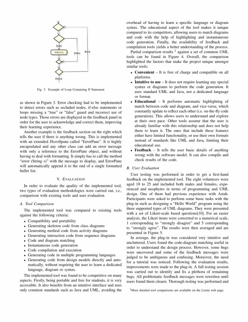
Fig. 3. Example of Loop Containing If Statement
as shown in Figure 3. Error checking had to be implementedto detect errors such as secluded nodes, if-else statements orloops missing a “true” or “false” guard and incorrect use ofnode types. Those errors are displayed in the feedback panel inorder for the user to acknowledge and correct them, improvingtheir learning experience.
Another example is the feedback section on the right whichtells the user if there is anything wrong. This is implementedwith an extended JScrollpane called “ErrorPane”. It is highlyencapsulated and any other class can add an error messagewith only a reference to the ErrorPane object, and withouthaving to deal with formatting. It simply has to call the method“error (String s)” with the message to display, and ErrorPanewill automatically append it to the end of a single formattedbullet list.
V. EVALUATION
In order to evaluate the quality of the implemented tool,two types of evaluation methodologies were carried out, i.e.,comparison with existing tools and user evaluation.
A. Tool Comparison
The implemented tool was compared to existing toolsagainst the following criteria:
• Compatibility and portability• Generating skeleton code from class diagrams• Generating method code from activity diagrams• Generating interaction code from sequence diagrams• Code and diagram matching• Instantaneous code generation• Code compilation and execution• Generating code in multiple programming languages• Generating code from design models directly and auto-
matically, without requiring the user to learn a dedicatedlanguage, diagram or syntax.
The implemented tool was found to be competitive on manyaspects. Firstly, being portable and free for students, it is veryaccessible. It also benefits from an intuitive interface and usesonly common standards such as Java and UML, avoiding the
overhead of having to learn a specific language or diagramsyntax. The educational aspect of the tool makes it uniquecompared to its competitors, allowing users to match diagramsand code with the help of highlighting and instantaneouscode generation. Finally, the availability of feedback andcompilation tools yields a better understanding of the process.
Partial comparison results 2 against a set of common UMLtools can be found in Figure 4. Overall, the comparisonhighlighted the factors that make the project unique amongstsimilar tools:
• Convenient – It is free of charge and compatible on allplatforms.
• Intuitive to use – It does not require learning any specialsyntax or diagrams to perform the code generation. Ituses standard UML and Java, not a dedicated languageor format.
• Educational – It performs automatic highlighting ofmatch between code and diagram, and vice-versa, whichconstantly update to reflect each other (i.e. on-the-fly codegeneration). This allows users to understand and exploreat their own pace. Other tools assume that the user isalready familiar with this relationship and does not helpthem to learn it. The ones that include these featureseither have limited functionality, or use their own formatsinstead of standards like UML and Java, limiting theireducational use.
• Feedback – It tells the user basic details of anythingwrong with the software model. It can also compile andcheck results of the code.
B. User Evaluation
User testing was performed in order to get a first-handfeedback on the implemented tool. The eight volunteers wereaged 18 to 25 and included both males and females, expe-rienced and neophytes in terms of programming and UMLdesign. One of them had previous experience with Astah.Participants were asked to perform some basic tasks with theplug-in such as designing a “Hello World” program using thethree supported types of UML diagrams. They were presentedwith a set of Likert-scale based questions[10]. For an easieranalysis, the Likert items were converted to a numerical scale,1 corresponding to “strongly disagree” and 5 correspondingto “strongly agree”. The results were then averaged and arepresented in Figure 5.
In average, the plug-in was considered very intuitive anduncluttered. Users found the code-diagram matching useful inorder to understand the design process. However, some bugswere uncovered and some of the feedback messages werejudged to be ambiguous and confusing. Moreover, the needfor a tutorial was noticed. Following the evaluation results,improvements were made to the plug-in. A full testing sessionwas carried out to identify and fix a plethora of remainingbugs. All problematic feedback messages were rewritten untilusers found them clearer. Thorough testing was performed and
2More detailed tool comparisons are available on the Lorini web page.

Fig. 4. Tool Comparison Results
Fig. 5. User Evaluation Results
all uncovered bugs were fixed. The full tutorial was embeddedinto the plug-in to help with the understanding of the tool.
VI. CONCLUSION
While Model Driven Engineering is proven to be time-efficient and less prone to human errors, research showedthat design models are scarcely used, mostly due to lackof education and training in the matter. In parallel, it hasbeen shown that teaching design modelling to students beforeprogramming is feasible and even beneficial. These formedthe basis of an educational approach that uses automaticcode generation to teach Object-Oriented Programming andits relationship with design models. The implemented tool isa plug-in for Astah able to automatically generate Java codefrom three types of UML diagrams, namely activity, sequenceand class diagrams. The tool includes the following features:
• Instantaneous code generation• Code-diagram matching• Feedback panel displaying user errors• Compilation and execution of the code
Evaluation of the tool indicated it to be competitive in manyaspects, mainly due to its unique educational features, as wellas being easy to install and very intuitive to use.
In the future, we plan to conduct a large scaled userevaluation and focus more on measuring the education aspectsof the developed tool. On the technical side, we would liketo extend the current implementation to support the codegeneration in different programming languages, and from othertypes of UML diagrams.
REFERENCES
[1] M. Becucci, A. Fantechi, M. Giromini, and E. Spinicci, “A comparisonbetween handwritten and automatic generation of c code from sdl usingstatic analysis,” Software: Practice and Experience, vol. 35, no. 14, pp.1317–1347, 2005.
[2] G. Nisha, “A model driven approach for design and development of asafety critical system,” in Electronics Computer Technology (ICECT),2011 3rd International Conference on, vol. 4, April 2011, pp. 15–18.
[3] H. Zhu, J. Sun, J. S. Dong, and S.-W. Lin, “From verified modelto executable program: the pat approach,” Innovations in Systems andSoftware Engineering, vol. 12, no. 1, pp. 1–26, 2015.
[4] T. Gorschek, E. Tempero, and L. Angelis, “On the use of softwaredesign models in software development practice: An empiricalinvestigation,” J. Syst. Softw., vol. 95, pp. 176–193, Sep. 2014.
[5] B. Tekinerdogan, “Experiences in teaching a graduate course onmodel-driven software development,” Computer Science Education,vol. 21, no. 4, pp. 363–387, 2011.
[6] C. Starrett, “Teaching uml modeling before programming at the highschool level,” in Advanced Learning Technologies, 2007. ICALT 2007.Seventh IEEE International Conference on, July 2007, pp. 713–714.
[7] R. Rivera-Lopez, E. Rivera-Lopez, and A. Rodriguez-Leon, “Anotherapproach for the teaching of the foundations of programming usingUML and Java,” in Proceedings of the 3rd WSEAS InternationalConference on Computer Engineering and Applications, ser. CEA’09.Stevens Point, Wisconsin, USA: World Scientific and EngineeringAcademy and Society (WSEAS), 2009, pp. 279–283.
[8] F. Krichen, B. Hamid, B. Zalila, M. Jmaiel, and B. Coulette,“Development of reconfigurable distributed embedded systems with amodel-driven approach,” Concurrency and Computation: Practice andExperience, vol. 27, no. 6, pp. 1391–1411, 2015.
[9] M. Hinchey, J. Rash, and C. Rouff, “Requirements to design tocode: Towards a fully formal approach to automatic code generation,”Technical Report TM-2005-212774, NASA Goddard Space FlightCenter, Greenbelt, MD, USA, Tech. Rep., 2004.
[10] O. Laitenberger and H. M. Dreyer, “Evaluating the usefulness andthe ease of use of a web-based inspection data collection tool,” inSoftware Metrics Symposium, 1998. Metrics 1998. Proceedings. FifthInternational, Nov 1998, pp. 122–132.


![[SEKE 2014] Practical Human Resource Allocation in Software Projects Using Genetic Algorithm](https://img.pdfslide.us/doc/110x75/558d337cd8b42a3c678b462f/seke-2014-practical-human-resource-allocation-in-software-projects-using-genetic-algorithm.jpg)