Embed Size (px)
Citation preview

1146015C/rdc06 MAR 97
From: Commander, Naval Facilities Engineering Command, NAVFAC Criteria Office (Code 15C)To: Distribution
Subj: INTERIM TECHNICAL GUIDANCE (ITG) - CVN DREDGE DEPTH CRITERIA
Ref: (a) COMNAVSEASYSCOM ltr 11460 Ser 03D3/242 dtd 3 Jan 95(b) OPNAVINST 11010.20E, Part 5
Encl: (1) CVN Dredge Depths - Interim Technical Guidance with attachments
1. Purpose: The purpose of this guidance is to define dredge depth criteria for Nimitz Class Aircraft Carriers.This criteria establishes consistency in application to waterway dredging projects and will be incorporated intoexisting military criteria noted in paragraph 4.
2. Background: In San Diego, California, the Navy relied on a more quantitative approach to determine therequired dredge depths for several Military Construction Projects relating to CVN homeporting. This methodsaved the Navy over $20 million when compared to the Design Manual 26.1 method. This document is asummary of the method.
Reference (a) delineated the water depth requirements for Nimitz Class Aircraft Carriers transiting to andmoored at homeports, ports of call, and shipyards. It specified the minimum water depth required while theship is in the waterway; however, it did not specify dredge depth requirements. The minimum water depthrequired to operate carriers in inner channels and turning basins on the way to and at piers at home ports isbetween 49 and 50 feet depending on harbor salinity. These numbers are similar for ports of call. Due to thereduced displacement when visiting shipyards, the minimum water depth required to operate carriers in innerchannels and turning basins on the way to and at piers at shipyards is between 46 and 47 feet depending onharbor salinity.
Applying these requirements to determine dredge depths requires additional port specific information.
a. Reference (a) states that “the dredging project depth can be traded off with tides to obtain thenecessary water depth in inner channels and turning basins with the corresponding operational conditions.”Therefore, planners should consider channel accessibility and operational restrictions imposed when selectinga design water level above the extreme low water.

2
06 MAR 97
Subj: INTERIM TECHNICAL GUIDANCE (ITG) - CVN DREDGE DEPTH CRITERIA
b. Reference (a) states further that, “shallower and/or narrow channels and/or higher speeds will requiregreater allowance for squat.” Since narrow channel widths and greater speeds result in greater ship sinkageduring transit (squat), and thus deeper water, planners should also include these effects.
c. Reference (a) also states that “port specific fouling clearance studies can be performed if requestedand funded” to possibly reduce the 6.0 foot fouling clearance criteria. The clearance criteria was derived fromcondenser fouling studies on stationary ships berthed at NAVSTA Norfolk, VA in 1980. Locations thatexhibit more or less potential for fouling may require more or less clearance to prevent it.
d. Lastly, reference (a) states that “ship motions analyses of the remaining home ports and shipyardswill be completed...after receipt of funding.” The motion analyses that NAVFAC prepared for Mayport andSan Diego predicted days of access and generated nomographs for other locations. For channels subjected tosignificant waves, engineers and planners must evaluate these wave effects on ship motions.
Therefore, as noted in reference (a), facility engineers and planners should determine dredge depthrequirements by including the additional considerations of design water level, channel width and ship speedimpacts, dynamic effects of sea chest intake fouling, and wave effects. Additionally, they should includeeffects from sedimentation and dredging tolerances.
Reference (b) designates responsibilities of the Chief of Naval Operations, Lead Activities, Shore Activitieshaving assigned water areas, Public Works Centers and Public Works Lead Activities, Naval FacilitiesEngineering Command and Engineering Field Divisions, and Major Claimants regarding dredgingcoordination.
3. Criteria: The cognizant activity should determine the dredge depth requirements as noted in reference(b). Base these requirements on reference (a) including the effects of design water level, channel width, shipspeed, sea chest fouling, significant wave heights, sedimentation, and dredging tolerances according toenclosure (1).
4. Action:
a. Lead Activities and Shore Activities having assigned water areas – determine dredge depthrequirements for Nimitz class aircraft carriers according to enclosure (1).
3
06 MAR 97
Subj: INTERIM TECHNICAL GUIDANCE (ITG) - CVN DREDGE DEPTH CRITERIA
b. NAVFAC Headquarters, Engineering Field Divisions (EFDs) and Engineering Field Activities(EFAs).
(1) Provide technical advice and assistance to lead activities and shore activities having assignedwater areas.
(2) Plan, design, and construct channels in compliance with the guidance stated herein.
c. NAVFAC Criteria Office
(1) Revise the following criteria to incorporate the guidance stated herein:
Design Manual 26.1, “Harbors”NAVFAC P-80, “Facility Planning Criteria for Navy and Marine Corps Shore Installations”
(2) Provide technical advice and assistance to lead activities, shore activities having assigned waterareas, EFDs and EFAs.
5. Coordination: This ITG has been coordinated with CNO, COMNAVFACENGCOM,COMNAVSHORLANT, COMNAVAIRLANT, CINCPACFLT, COMNAVAIRPAC, andCOMNAVSEASYSCOM. See distribution below for specific codes.
6. Points of Contact: For clarification or additional information related to this subject, please contact theNAVFAC Criteria Office, Code 15C. The NAVFAC Criteria Office point of contact is Mr. David Curfman,P.E., DSN 262-4203/757-322-4203, Fax 757-322-4416, Internet [email protected].
R. D. CURFMANBy direction
Distribution:CNO N44/N43CNO N88COMNAVFACENGCOM Codes 00CE/15/30
4
06 MAR 97
Subj: INTERIM TECHNICAL GUIDANCE (ITG) - CVN DREDGE DEPTH CRITERIA
LANTNAVFACENGCOM Codes 20/405COMNAVSHORLANT N44COMNAVAIRLANT N43CINCPACFLT N44/N46COMNAVAIRPAC N43COMNAVSEASYSCOM Code 072COMNAVSEASYSCOM Codes 03D3/03H3COMNAVSEASYSCOM Codes 08J/08PCOMNAVSEASYSCOM PMS 312/312E/312MNAVSURFWARCEN CARDEROCKDIV Code 1561NFESC Code 64 (Biggers)NORTHNAVFACENGCOM Codes 4013 (D’Armi)/20PACNAVFACENGCOM Codes 406 (Takushi)/20SOUTHNAVFACENGCOM Code 076 (Dennis)SOUTHWESTNAVFACENGCOM Codes 406 (Flach)/20ENGFLDACT Chesapeake Code 406 (Trechsel)ENGFLDACT Mediterranean N4 (Cook)ENGFLDACT MW Code 420 (Kang)ENGFLDACT NW Code 04B (Jones)ENGFLDACT West Code 09F41 (Pittman)COMNAVBASE NorfolkCOMNAVBASE JacksonvilleCOMNAVBASE PensacolaCOMNAVBASE San DiegoCOMNAVBASE Puget SoundCOMNAVBASE Pearl HarborCOMNAVBASE Yokosuka
Blind copy to:15C/rdc15C(RF)/ssfc:/mydocuments/curfman/ltg-cvn.doc

5
CVN DREDGE DEPTHSINTERIM TECHNICAL GUIDANCE
4 March 1997
1. This guidance explains the determination of minimum dredge depth requirements for U.S. Navy nuclear-powered aircraft carriers (Nimitz or CVN 68 Class). The requirements presented herein provide consistency andreliability in the determination of acceptable dredge depths for channels and berths used by active Nimitz classaircraft carriers. The NAVFAC Criteria Office will address reserve status condition of CVNs when required.Deviation from this minimum criteria requires a waiver from the NAVFAC Criteria Office which will becoordinated with cognizant Major Claimants, Naval Sea Systems Command, and Chief of Naval Operations.
2. Ideally, engineers and planners should base ship channel designs on physical model testing, risk analysis, andship simulator analysis. However, time and funding constraints may prevent this process. In any event, therequesting activity should determine the required dredge depths for Military Construction Projects. Dredge depthrequirements for Nimitz class aircraft carriers depend on the type of waterway to be dredged. Four categories existbased on the magnitude of wave-induced and speed-induced ship movement:
a. Outer channels – entrance channels or waterways subject to significant wave action, that is, wave energyresulting in vertical ship motions greater than 0.5 feet under design conditions.
b. Inner channels – interior protected channels or waterways subject to minimal wave action, that is, wave
energy resulting in vertical ship motions less than 0.5 feet under design conditions. c. Berths – water areas where ship velocity approaches zero, such as anchorages, slips, and pier and wharf
berths that are subject to minimal wave action under design conditions; generally includes turning basinsexcept as noted below.
d. Special berths – defined as berths subject to significant wave action under design conditions.
3. The following definitions apply:
a. Datum – the horizontal plane from which the dredge depth requirement is referred, normally the localtidal datum of Mean Lower Low Water (MLLW).
b. Design depth – the distance below the datum that must be maintained for safe navigation and berthing,also called the advertised, nominal, or project depth.
This depth usually appears on Navigational Charts. c. Contract depth – the distance below the datum that is initially dredged by the contract and includes
advanced maintenance dredging requirements but not the dredging tolerance (allowable overdepth). Alsocalled the required depth, it is the depth noted on the DD-1391 Project Documentation and indicates theminimum depth required under the dredging contract.
d. Permitted depth – the distance below datum to the lowest depth authorized by the regulatory agencies and
normally includes the dredging tolerance (allowable overdepth). Planners and engineers should use thisdepth to determine estimated dredging quantities.
4. Determine required dredge depths using sound engineering practice. The design depth is determined bysumming the following parameters:
a. Minimum water depth requirement – the minimum water depth that must be available for safe operation.For existing locations, use COMNAVSEASYSCOM ltr 11460 Ser 03D3/242 dtd 3 Jan 95 (Attachment(a)) implemented as follows for design water level, squat, ship motions, and underkeel clearances. Forlocations not addressed in Attachment (a), contact the NAVFAC Criteria Office for assistance.

6
b. Design water level – the distance above the datum from which the dredge depth is calculated:
(1) Outer channels – use 0 feet. The design water level should equal the datum to provide enough waterdepth and ensure that the ship can transit when required.
(2) Inner channels and turning basins – use a water level that ensures safe passage to the berth or basin.
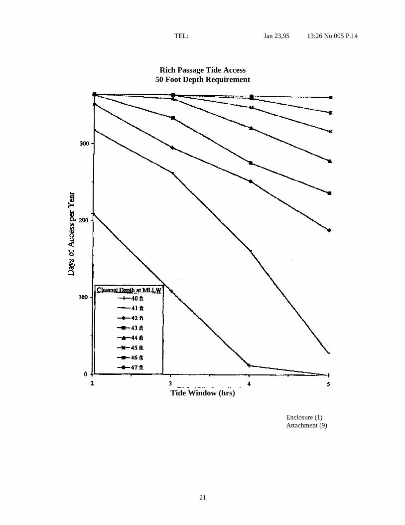
This water level should be selected by the Activity based on optimizing cost and operation. Shipoperators generally accept some minor operational restrictions and transit shallow channels at mid tohigh tide levels. Therefore, the design water level should be selected so that the carrier can transitfrom deep water to the berth, or vice versa, as frequently as expected without encroaching on theminimum water depth requirement noted in Attachment (a). The user should identify for the plannerthe expected ship transit speed and desired days of accessibility, realizing that slow transits at low tidelevels result in excessive dredge depths.
An example of this procedure is as follows:
(a) Determine level of accessibility; e.g. minimum of 339 days per year of access to homeports and300 days per year of access to shipyards and ports of call. These accessibility levels equate tooperational restrictions of approximately 2 consecutive days per month of encroachment on theunderkeel clearance for homeports and 5 consecutive days per month for shipyards and ports ofcall, respectively.
(b) Based on local traffic and regulations, assume an average ship speed through channel; e.g. 5knots.
(c) Using assumed transit speed and navigational charts, calculate the time required to accomplishthe transit from the outer channel to the turning basin or berth.
(d) Using the calculated transit time, days of accessibility, and the charts in attachment (a),determine the channel depth requirement.
(e) Subtract the water depth requirement from the channel depth requirement to obtain the designwater level. This number will usually be negative and thus result in a design water level aboveMLLW.
(3) All berths, except turning basins – use 0 feet. Since 6 feet of clearance is provided, as noted later, thedesign water level may equal the datum (MLLW).
c. Squat – the downward displacement of a vessel while underway. Attachment (a) incorporates squat forinfinitely wide channels with ship speeds equal to or less than 10 knots. Ship squat greatly increases whenCVNs transit channels less than 600 feet in width or move at speeds faster than 10 knots. To determinesquat for conditions other than those addressed in Attachment (a), use the method contained in NAVFACDesign Manual (DM) 26.1, “Harbors” dated July 1981. All channels normally used by aircraft carriers inthe U.S., except the Southern Branch, Lower Reach, of the Elizabeth River, Norfolk, VA (450 feet atnarrowest point) and the Entrance Channel, Mayport, FL (500 feet at narrowest point), are wide enough tobe considered infinitely wide. For these narrow channels, the squat increases by 2 feet. The water depthrequirement determined above should be modified to incorporate any difference in calculated squat.
(1) Outer channels – assume ship speed of 15 knots. (2) Inner channels – base on local traffic and regulations, as a minimum assume an average ship speed
through channel of 10 knots and include the effects of narrow channels as noted above.

7
(3) Berths and special cases – assume ship speed of zero.
d. Ship motion – vertical excursion of vessel from waves. Attachment (a) addresses ship motions only for
San Diego and Mayport. For other locations, use nomographs in Attachment (b). Hs is defined as thesignificant wave height. Each set of nomographs reflects the direction of the significant wave relative tothe direction of the CVN in transit; i.e., Following Seas are collinear with and in the same direction ofship movement, Quartering Seas are those that approach the aft quarter of the ship at 45 degrees, BeamSeas impact broadside to the ship, Bow Seas are those that approach the forward quarter of the ship at 45degrees, and Head Seas are collinear with but opposite to the ship movement. The wave height and periodshould be transformed to and through the channel entrance using local wave data or Army Corps ofEngineers reports entitled, “Wave Information Studies of U.S. Coastlines” (Studies 1-30).
(1) Outer channels -- use Hs for periods greater than 10 seconds with a 6 days/month recurrence intervalunless directed differently by the Activity. Exclude hurricane waves.
An example of this procedure is as follows:
(a) Determine the wave climatology. Using available data determine the significant wave height,direction, and period. Transform waves into harbor based on shoaling, refraction, anddiffraction, etc.
(b) Based on local traffic and regulations, assume an average ship speed through channel; e.g. 14knots.
(c) Using the calculated wave climatology, assumed ship speed, and the charts in Attachment B,determine the predicted vertical ship motion for all applicable directions.
(2) Inner channels and berths – use Hs = 0.
(3) Special cases – use Hs for periods greater than 10 seconds with a 25 yr.recurrence interval, unless directed differently by the Activity. Include hurricane waves if the berth isexpected to be occupied during that extreme event.
e. Clearance – distance from the lowest point on the vessel to the design depth. For berths, turning basins,and inner channels, Attachment (a) incorporates a 6 foot clearance to prevent ingestion of benthic biota.This clearance when combined with installed discharge diffusers reduces the possibility of condenserfouling. Additional studies may reduce the requirement and can be performed if funded. The designermust collect all historical data available regarding fouling of condensers to ascertain the extent of theproblem. The NAVFAC Criteria Office is available to assist in analyzing this data. Notwithstanding, atberths the designer must ensure that a minimum of 2 feet of clearance is provided at Extreme Low Water.See table below for other categories:
RECOMMENDED CLEARANCES
LOCATION CATEGORY SOFT BOTTOM HARD BOTTOM1. Outer channel 3.0 feet for 50 feet depth
4.4 feet for 54 feet depth5.5 feet for > 58 feet depth
4.0 feet for < 52 feet depth5.5 feet for > 58 feet depth
2. Special berths 6 feet (min.) coupled withdischarge diffusers
6 feet (min.) coupled withdischarge diffusers
8
5. Determine the contract depth by adding the advanced maintenance dredging requirement to the design depthrequirement. The advanced maintenance dredging is the additional depth to reduce life-cycle maintenance costs bydecreasing the frequency of dredging. Base the quantity on the anticipated local channel sedimentation ratescorresponding to the anticipated dredging cycle. Unless an economic analysis is performed, use a dredgingfrequency of not less than 3 years, but based on local conditions. Include a minimum of 1 foot advancedmaintenance dredging to prevent contractor change orders for differing site conditions on future maintenancedredging contracts. This minimum also provides the Contracting Officer field flexibility if the contractor does notachieve the contract depth in spot locations. The dredging tolerance, or overdredge, is the additional depth belowthe contract depth paid for by the dredging contract. The contract permits this additional depth because ofinaccuracies in the dredging process. It is normally either +1 or +2 feet. Local conditions and anticipateddredging equipment may warrant a different value. NAVFAC Textbook DM 38.2, “Dredging Equipment”provides additional information.
6. Determine the permitted depth by adding the dredging tolerance, or overdredge, to the contract depth.Material samples for environmental testing should be accomplished at least to this depth.

9
DEPARTMENT OF THE NAVYNAVAL SEA SYSTEMS COMMAND2631 JEFFERSON DAVIS HIGHWAY
ARLINGTON VA 22242-5160IN REPLY REFER TO
11460Ser 03D3/2423 Jan 95
From: Commander, Naval Sea Systems CommandTo: Chief of Naval Operations (W44) Chief of Naval Operations (WB8)
Subj: CVN 68 CLASS WATER DEPTH REQUIREMENTS
Ref: (a) NAVSEA ltr 11460 Ser PMS312/792 of 30 Apr 91(b) NAVSEA ltr 11460 Ser 03D3/144 of 9 Aug 94(c) COMNAVAIRLANT ltr 4700 Ser N431F/01400 of 19 May 94
Encl: (1) CNV 68 C1ass Home Port Water Depth Requirements(2) CVN 68 Class Shipyard Water Depth Requirements(3) CVN 68 Class Shallow Water Navigation Improvements
1. NAVSEA has determined the water depth requirements for CVN 68 Classaircraft carriers in home ports, ports of call, and shipyards. The pier andchannel depths requirements previously provided in reference (a) aresuperseded. These water depth requirements augment those previously providedfor San Diego in reference (b), and respond to the reference (c) request forNorfolk Naval Shipyard.
2. Enclosure (1) provides water depth requirements for home ports.Attachment (1) of enclosure (1) also applies to ports of call. The ship’smean draft used for home ports corresponds to the limiting displacement and isconsidered the proper basis for dredging since it will permit operations of afully loaded ship. Enclosure (2) provides water depth requirements forshipyards. The ship’s mean draft used for shipyards was reduced based on theassumption that only 55% of the sbip's loads (aircraft, fuel, personnel,stores, etc) would be onboard. Each enclosure describes and quantifies thecomponents that contribute to the CVN 68 Class draft and clearance; thegoverning depth requirements for the pier, turning basin, inner channel, andouter channel for each home port and shipyard; general tide information foreach home port and shipyard; and a graphical representation of therelationship between the number of days of access to the turning basin andinner channel, the length of the tide window, and the dredging project depthfor the governing depth requirement of each home port and shipyard.
3. While at the pier, in the turning basin, or in the inner channel of ahome port or a port of call, it is recommended that there be a minimum of 50feet of water depth. While at the pier, in the turning basin, or in the innerchannel of a shipyard, it is recommended that there be a minimum of 47 feet ofwater depth, assuming the ship has been offloaded. Entering a shipyardwithout offloading should be treated as a port of call. These water depthrequirements are governed by the sea chest fouling
Attachment (a)

10
TEL: Jan 23,95 13:19 No.005 P.03
Subj: CVN 68 CLASS WATER DEPTH REQUIREMENTS
clearance criterion established as a result of sea chest fouling problems atNorfolk. Port specific fouling clearance studies can be performed itrequested and funded. Note that this criterion also provides clearance fordivers (5 feet) while at the pier. The dredging project depth can be tradedoff with tides to obtain the necessary water depth in inner channels andturning basins with the corresponding operational restrictions; however, tidetradeoffs cannot be used at piers. Localized pier dredging in way of seachests can save 2 feet of dredging costs outside of the sea cheat area;however, operational restrictions may result (e.g. lesstransit time in tide window and limited diver access). In ports with largeamounts of debris on the bottom, locally dredged areas will tend to collectdebris requiring more frequent maintenance dredging.
4. In the outer channel, wave action usually dominates the depthrequirements and can have a large variance. A ship motions analysis wasperformed for the outer channels of San Diego and Mayport to account for thestatistical nature of the tides and wave action. The ship motions analyses ofthe remaining home ports and shipyards will be completed within 6 months afterreceipt of funding. Dredging to support unrestricted access is clearlyunaffordable. Consequent1y, the selection of a project depth is a tradeoffbetween cost, operational requirements, and the risk of grounding.
5. Many of the factors that affect channel transit are operational issuessuch as operating schedule and contingencies; port operations; shipdisplacement, trim, list, and speed; as well as weather and tides. Actualtransit situations will vary and will involve different combinations of thesefactors. Consequently, a given transit could require more or less waterdepth. Enclosure (3) describes efforts underway or proposed to improveonboard shallow water navigation aids that predict ship’s motion, provide realtime channel condition measurement, improve ship's draft and attitudeindication, and provide a load management system.
6, The NAVSEA point of contact is W. Page Glennie, NAVSEA 03D37, (703) 4I8-8876.
M. S. FIREBAUGHDeputy Commander for Engineering
Copy to: (w/encls)OPNAV (Code N43)NAVFAC (Code 15)COMNAVAIRLANT (Code N43, N02N)COMNAVAIRPAC (Code N43, N7N)CINCLANTFLT (Code N4, N43)CINCPACFLT (Code N4, N43)NSWC-CD (Code 1561)NAVSEA DET PERA CV (Code 1824)
2

11
TEL Jan 23,95 13:19 No.005 P.04
Subj CVN 68 CLASS WATER DEPTH REQUIREMENTS
Blind copy to: (w/encls)SEA 03
03D03D3703H03H307207Q08J08P
PMS312PMS3l2EPMS312X
Writer: W. Page Glennie, SEA 03D37, 418-8876Typist: W. Page Glennie, SEA 03D37, 418-8876

12
TEL: Jan 23,95 13:19 No.005 P.05
CVN 68 CLASS HOME PORT WATER DEPTHREQUIREMENTS
Attachments:(1) CVN 68 Class Home Port and Ports of Call Draft and Clearance Requirements(2) CVN 68 Class Water Depth Requirements for Norfolk Operating Base(3) Sewell's Point Tide Access, 50 foot Depth Requirement(4) CVN 68 Class Water Depth Requirements for San Diego(5) San Diego Inner Channel Tide Access, 50 foot Depth Requirement(6) CVN 68 Class Water Depth Requirements for Everett(7) Everett Tide Access, 50 foot Depth Requirement(8) CVN 68 Class Water Depth Requirements for Bremerton(9) Rich Passage Tide Access, 50 foot Depth Requirement(10) CVN 68 Class Water Depth Requirements for Mayport(11) Mayport Tide Inner Channel Access, 50 foot Depth Requirement
Enclosure (1)

13
TEL: Jan 23,95 13:21 No .005 P. 06
CVN 68 Class Home Port and Ports of Call Draft and Clearance Requirements
STATIC DRAFTMean 40.8 ft
103,800 tons (CVN 68-75)104,200 tons (CVN 76)
− Accounts for: Actual operating condition (+2000 tons) Service life weight growth (+70 tons/year) Unreported weight
Assumes weight is added in best location. Assumes good ship weight control.
Trim 0.25degrees
BowSea ChestRudder
2.3 ft0.8 ft2.1 ft
− Based on operational experience. Instances ofgreater trim do occur, but rarely when the ship isat or near the limiting displacement.
List Pier 2degrees
Bilge KeelSea Chest
2.3 ft1.4 ft
− Based on operational experience. Instances ofgreater list do occur, but rarely when the ship isat the limiting displacement.
Channel 0 degrees − Assumed ship is leveled prior to transit.TYCOM confirmation needed
Appendages 9 inches − All of the CVN 68 Class except CVN 70 havedischarge sea chest diffusers.
− Assumed to be overshadowed by trim.
Salinity &Temperature
0.5 feet(50% salinity reduction & 10o temperature rise)
− This calculation is port, season, and tide specific.− Assumed constant.
Dynamic Draft
WindOuter Channel See Note − This calculation is port specific.
− See indiv. port summary sheet for details.
& Inner Channel 0 ft − Protected harbor.
Waves Pier & Turning BasinSquat 10 kts Forward 0.9 ft − Based on wide channel that is 50 ft deep.
Aft 1.3 ft − Shallower and/or narrower channels a/o higher
Sea Chest 1.0 ft speeds will require a greater allowance for squat
Heel 1.4 Bilge Keel 1.6 ft − Based on operational experience, 10 kts and
degrees Sea Chest 0.8 ft 10 degrees rudder.
ClearanceFouling 6 ft − Based on operational experience at NOB and
NAVFAC study and applies to soft bottoms andbottoms with loose sea growth.
− Assumes diffusers are installed.
Grounding Soft Bottom 2 ft − NAVFAC deterministic standard.
Hard Bottom 3 ft− Proposed probabilistic standard.
Enclosure (1) Attachment (1)

14
TEL: Jan 23,95 13:22 No.005 P.07
CVN 68 Class Water Depth Requirements forNorfolk Operating Base
Pier Turning Basin Inner Channel Outer Channel
Draft 40.8 40.8 40.8 40.8Trim 0.8 0.8 0.8 2.1List 1.4 1.4 - -Appendages - - - -Salinity & Temp(a)
0.5 0.5 0.5 0.5
Motions (b) - - - (f)Squat (c) - - 1.0 1.3Heel (d) - - 0.8 -Clearance (e) 6.0 6.0 6.0 2.0TOTAL 49.5 49.5 49.9 (f)
Notes: (a) Harbor contains fresh water inlet.(b) Unprotected harbor; significant wave action.(c) Based on wide, 50 ft deep channel; good estimate.(d) Operational experience.(e) Standard clearances.(f) Analysis not complete.
NOB Tide Data
Mean Higher High Water 2.8 feetMean Lower Low Water 0.0 feet
Extreme Low Water -3.5 feet
Enclosure (1)Attachment (2)

15
TEL: Jan 23,95 13:22 No.005 P.08
Sewell's Point Tide Access50 Foot Depth Requirement
Tide Window (hrs)
Enclosure (1)Attachment (3)
16
TEL: Jan 23,95 13:23 No.005 P.09
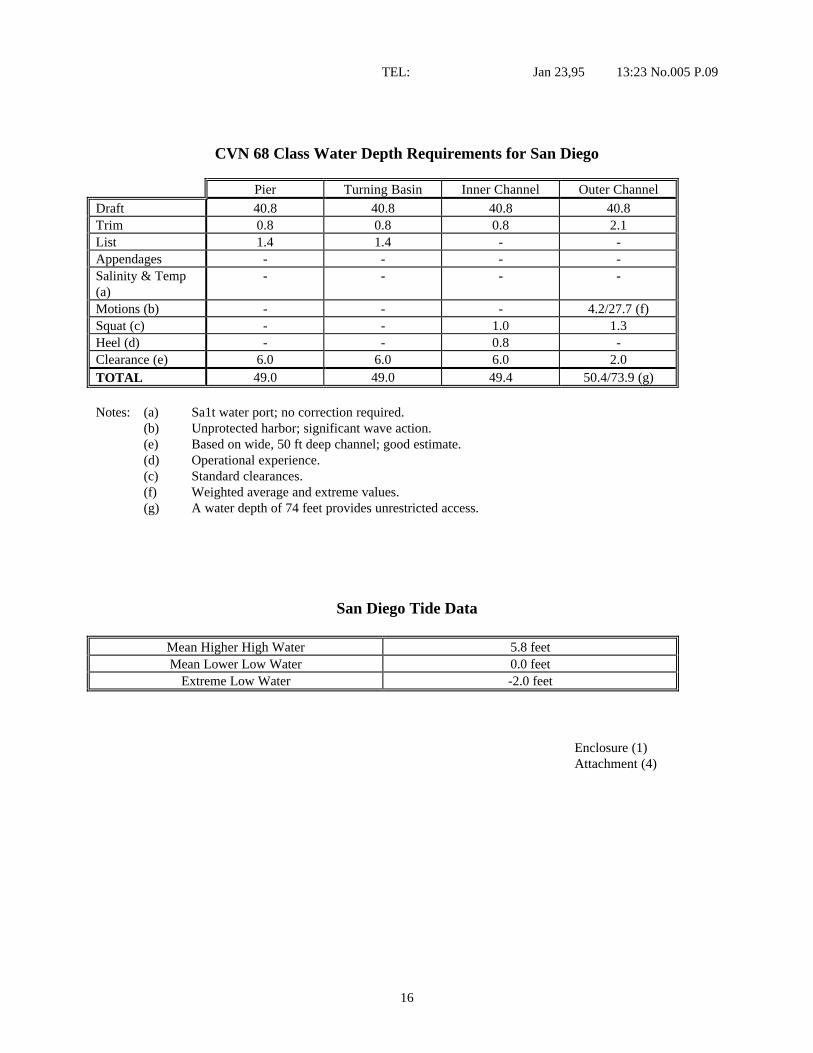
CVN 68 Class Water Depth Requirements for San Diego
Pier Turning Basin Inner Channel Outer Channel
Draft 40.8 40.8 40.8 40.8Trim 0.8 0.8 0.8 2.1List 1.4 1.4 - -Appendages - - - -Salinity & Temp(a)
- - - -
Motions (b) - - - 4.2/27.7 (f)Squat (c) - - 1.0 1.3Heel (d) - - 0.8 -Clearance (e) 6.0 6.0 6.0 2.0TOTAL 49.0 49.0 49.4 50.4/73.9 (g)
Notes: (a) Sa1t water port; no correction required.(b) Unprotected harbor; significant wave action.(e) Based on wide, 50 ft deep channel; good estimate.(d) Operational experience.(c) Standard clearances.(f) Weighted average and extreme values.(g) A water depth of 74 feet provides unrestricted access.
San Diego Tide Data
Mean Higher High Water 5.8 feetMean Lower Low Water 0.0 feet
Extreme Low Water -2.0 feet
Enclosure (1)Attachment (4)
17
TEL Jan 23,95 13:23 No.005 P.10
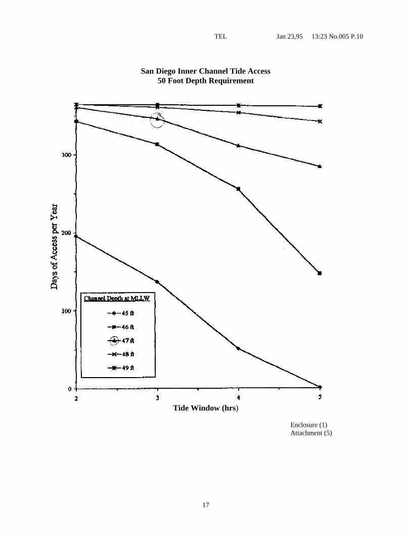
San Diego Inner Channel Tide Access50 Foot Depth Requirement
Tide Window (hrs)
Enclosure (1)Attachment (5)

18
TEL. Jan 23,95 13:23 No.005 P.11
CVN 68 Class Water Depth Requirements for Everett
Pier Turning Basin Inner Channel Outer Channel
Draft 40.8 40.8 40.8Trim 0.8 0.8 0.8List 1.4 1.4AppendagesSalinity & Temp (a) 0.5 0.5 0.5 (f)Motions (b)Squat (c) 1.0Heel (d) 0.8Clearance (e) 6.0 6.0 6.0TOTAL 49.5 49.5 49.9
Notes: (a) Harbor contains fresh water inlet.(b) Protected harbor; no significant wave action,(C) Based on wide, 50 ft deep channel; need more information.(d) Operational experience.(e) Standard clearances,(f) Unrestricted outer channel due to deep depth.
Everett Tide Data
Mean Higher High Water 11.1 feetMean Lower Low Water 0.0 feet
Extreme Low Water -4.5 feet
Enclosure (1)Attachment (6)
19
TEL: Jan 23,95 13:25 No.005 P.12
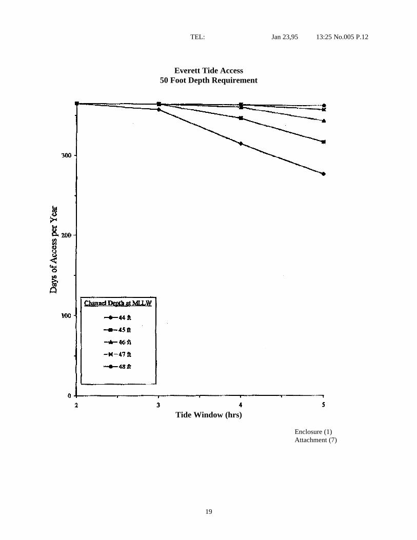
Everett Tide Access50 Foot Depth Requirement
Tide Window (hrs)
Enclosure (1)Attachment (7)
20
TEL: Jan 23,95 13:25 No.005 P. 13
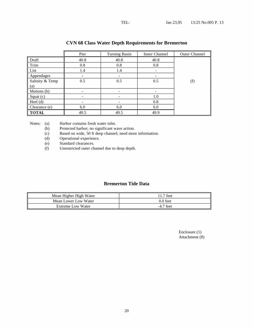
CVN 68 Class Water Depth Requirements for Bremerton
Pier Turning Basin Inner Channel Outer Channel
Draft 40.8 40.8 40.8Trim 0.8 0.8 0.8List 1.4 1.4 -Appendages - - -Salinity & Temp(a)
0.5 0.5 0.5 (f)
Motions (b) - - -Squat (c) - - 1.0Heel (d) - - 0.8Clearance (e) 6.0 6.0 6.0TOTAL 49.5 49.5 49.9
Notes: (a) Harbor contains fresh water inlet.(b) Protected harbor; no significant wave action.(c) Based on wide, 50 ft deep channel; need more information.(d) Operational experience.(e) Standard clearances.(f) Unrestricted outer channel due to deep depth.
Bremerton Tide Data
Mean Higher High Water 11.7 feetMean Lower Low Water 0.0 feet
Extreme Low Water -4.7 feet
Enclosure (1)Attachment (8)
21
TEL: Jan 23,95 13:26 No.005 P.14
Rich Passage Tide Access50 Foot Depth Requirement
Tide Window (hrs)
Enclosure (1)Attachment (9)

22
TEL: Jan 23,95 13:26 No.005 P.15
CVN 68 Class Water Depth Requirements for Mayport
Pier Turning Basin Inner Channel Outer Channel
Draft 40.8 40.8 40.8 40.8Trim 0.8 0.8 0.8 0.8/2.1List 1.4 1.4 - -Appendages - - - -Salinity & Temp(a)
0.5 0.5 0.5 0.5
Motions (b) - - - 0.5/14.3 (f)Squat (c) - - 1.0 1.0/1.3Heel (d) - - 0.8 -Clearance (e) 6.0 6.0 6.0 6.0/2.0TOTAL 49.5 49.5 49.9 49.6/61.0 (g)
Notes. (a) Harbor contains fresh water inlet.(b) Unprotected harbor; significant wave action.(c) Based on wide, 50 ft deep channel; need more information.(d) Operational experience.(e) Standard clearances.f) Weighted average value at sea chest and extreme value at rudder.(g) A water depth of 61 feet provides unrestricted access.
The minimum water depth (50 feet) is governed by fouling.
Mayport Tide Data
Mean Higher High Water 5.4 feetMean Lower Low Water 0.0 feet
Extreme Low Water -3.0 feet
Enclosure (1)Attachment (10)

23
TEL Jan 23,95 13:27 No.005 P.16
Mayport Inner Channel Tide Access50 Foot Depth Requirement
Tide Window (hrs)
Enclosure (1)Attachment (11)
24
TEL Jan 23,95 13:27 No.005 P.17
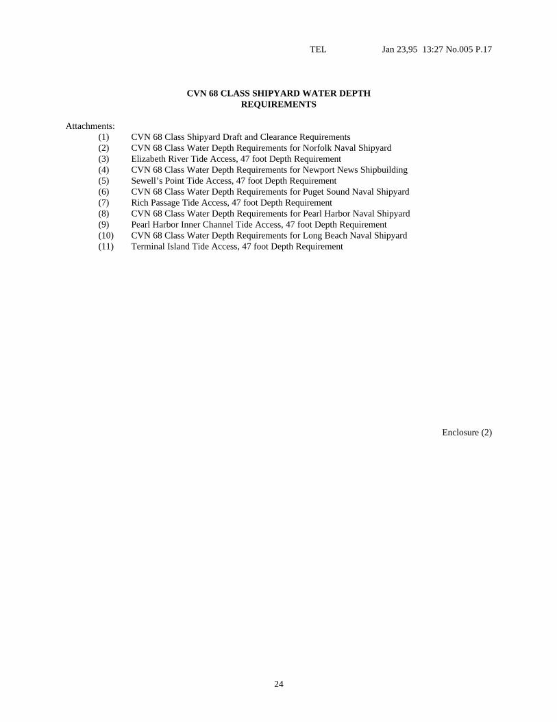
CVN 68 CLASS SHIPYARD WATER DEPTHREQUIREMENTS
Attachments:(1) CVN 68 Class Shipyard Draft and Clearance Requirements(2) CVN 68 Class Water Depth Requirements for Norfolk Naval Shipyard(3) Elizabeth River Tide Access, 47 foot Depth Requirement(4) CVN 68 Class Water Depth Requirements for Newport News Shipbuilding(5) Sewell’s Point Tide Access, 47 foot Depth Requirement(6) CVN 68 Class Water Depth Requirements for Puget Sound Naval Shipyard(7) Rich Passage Tide Access, 47 foot Depth Requirement(8) CVN 68 Class Water Depth Requirements for Pearl Harbor Naval Shipyard(9) Pearl Harbor Inner Channel Tide Access, 47 foot Depth Requirement(10) CVN 68 Class Water Depth Requirements for Long Beach Naval Shipyard(11) Terminal Island Tide Access, 47 foot Depth Requirement
Enclosure (2)
25
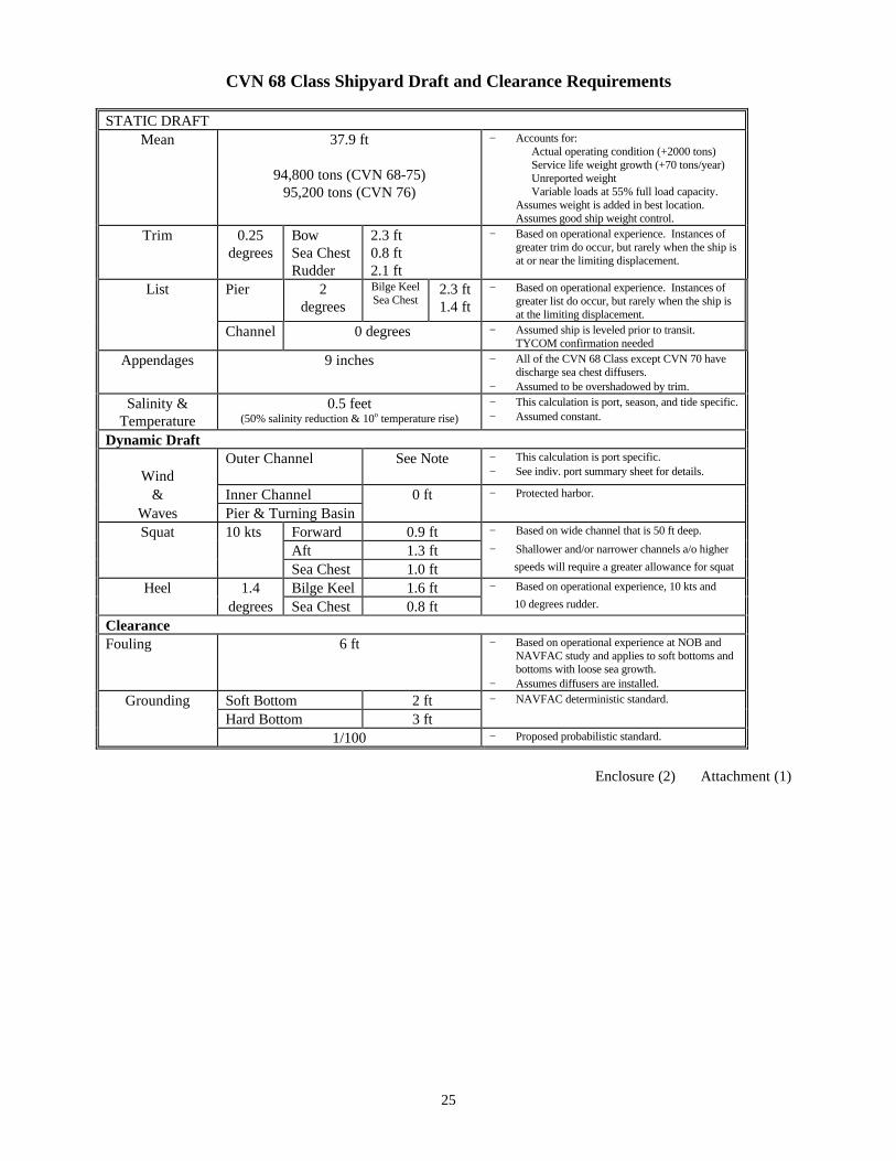
CVN 68 Class Shipyard Draft and Clearance Requirements
STATIC DRAFTMean 37.9 ft
94,800 tons (CVN 68-75)95,200 tons (CVN 76)
− Accounts for: Actual operating condition (+2000 tons) Service life weight growth (+70 tons/year) Unreported weight Variable loads at 55% full load capacity.
Assumes weight is added in best location. Assumes good ship weight control.
Trim 0.25degrees
BowSea ChestRudder
2.3 ft0.8 ft2.1 ft
− Based on operational experience. Instances ofgreater trim do occur, but rarely when the ship isat or near the limiting displacement.
List Pier 2degrees
Bilge KeelSea Chest
2.3 ft1.4 ft
− Based on operational experience. Instances ofgreater list do occur, but rarely when the ship isat the limiting displacement.
Channel 0 degrees − Assumed ship is leveled prior to transit.TYCOM confirmation needed
Appendages 9 inches − All of the CVN 68 Class except CVN 70 havedischarge sea chest diffusers.
− Assumed to be overshadowed by trim.
Salinity &Temperature
0.5 feet(50% salinity reduction & 10o temperature rise)
− This calculation is port, season, and tide specific.− Assumed constant.
Dynamic Draft
WindOuter Channel See Note − This calculation is port specific.
− See indiv. port summary sheet for details.
& Inner Channel 0 ft − Protected harbor.
Waves Pier & Turning BasinSquat 10 kts Forward 0.9 ft − Based on wide channel that is 50 ft deep.
Aft 1.3 ft − Shallower and/or narrower channels a/o higher
Sea Chest 1.0 ft speeds will require a greater allowance for squat
Heel 1.4 Bilge Keel 1.6 ft − Based on operational experience, 10 kts and
degrees Sea Chest 0.8 ft 10 degrees rudder.
ClearanceFouling 6 ft − Based on operational experience at NOB and
NAVFAC study and applies to soft bottoms andbottoms with loose sea growth.
− Assumes diffusers are installed.
Grounding Soft Bottom 2 ft − NAVFAC deterministic standard.
Hard Bottom 3 ft1/100 − Proposed probabilistic standard.
Enclosure (2) Attachment (1)
26
TEL: Jan 23,95 13:29 No.005 P.19
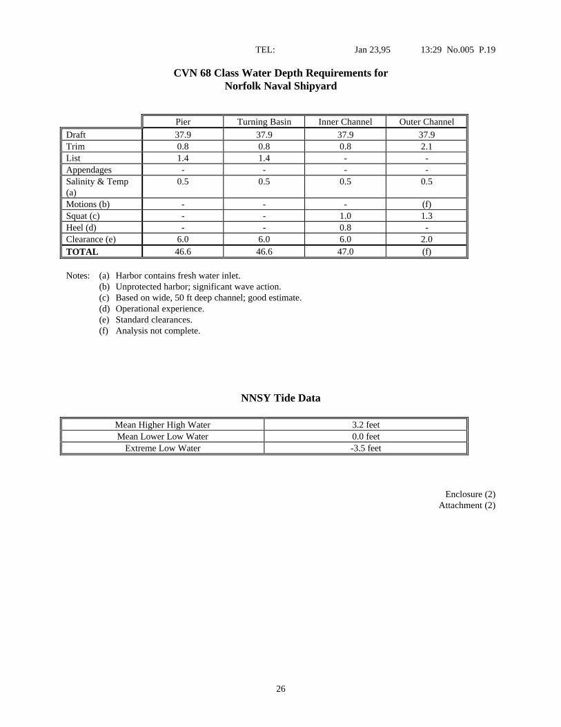
CVN 68 Class Water Depth Requirements forNorfolk Naval Shipyard
Pier Turning Basin Inner Channel Outer Channel
Draft 37.9 37.9 37.9 37.9Trim 0.8 0.8 0.8 2.1List 1.4 1.4 - -Appendages - - - -Salinity & Temp(a)
0.5 0.5 0.5 0.5
Motions (b) - - - (f)Squat (c) - - 1.0 1.3Heel (d) - - 0.8 -Clearance (e) 6.0 6.0 6.0 2.0TOTAL 46.6 46.6 47.0 (f)
Notes: (a) Harbor contains fresh water inlet.(b) Unprotected harbor; significant wave action.(c) Based on wide, 50 ft deep channel; good estimate.(d) Operational experience.(e) Standard clearances.(f) Analysis not complete.
NNSY Tide Data
Mean Higher High Water 3.2 feetMean Lower Low Water 0.0 feet
Extreme Low Water -3.5 feet
Enclosure (2)Attachment (2)

27
TEL: Jan 23,95 13:29 No.005 P.20
Elizabeth River Tide Access47 Foot Depth Requirement
Tide Window (hrs)
Enclosure (2)Attachment (3)
28
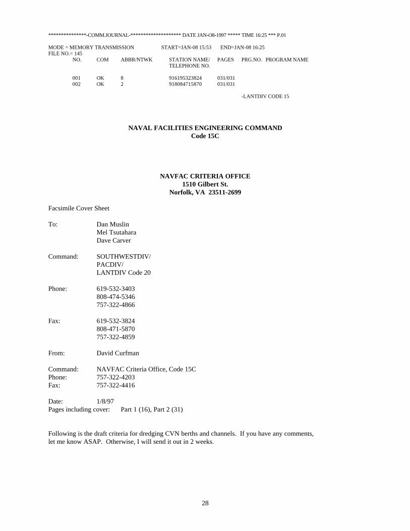
***************-COMM.JOURNAL-******************** DATE JAN-O8-1997 ***** TIME 16:25 *** P.01
MODE = MEMORY TRANSMISSION START=JAN-08 15:53 END=JAN-08 16:25FILE NO.= 145
NO. COM ABBR/NTWK STATION NAME/ PAGES PRG.NO. PROGRAM NAMETELEPHONE NO.
001 OK 8 916195323824 031/031002 OK 2 918084715870 031/031
-LANTDIV CODE 15
NAVAL FACILITIES ENGINEERING COMMANDCode 15C
NAVFAC CRITERIA OFFICE1510 Gilbert St.
Norfolk, VA 23511-2699
Facsimile Cover Sheet
To: Dan MuslinMel TsutaharaDave Carver
Command: SOUTHWESTDIV/PACDIV/LANTDIV Code 20
Phone: 619-532-3403808-474-5346757-322-4866
Fax: 619-532-3824808-471-5870757-322-4859
From: David Curfman
Command: NAVFAC Criteria Office, Code 15CPhone: 757-322-4203Fax: 757-322-4416
Date: 1/8/97Pages including cover: Part 1 (16), Part 2 (31)
Following is the draft criteria for dredging CVN berths and channels. If you have any comments,let me know ASAP. Otherwise, I will send it out in 2 weeks.

29
CVN 68 Class Water Depth Requirements forNewport News Shipbuilding
Pier Turning Basin Inner Channel Outer Channel
Draft 37.9 37.9 37.9 37.9Trim 0.8 0.8 0.8 2.1List 1.4 1.4 - -Appendages - - - -Salinity & Temp(a)
0.5 0.5 0.5 0.5
Motions (b) - - - (f)Squat (c) - - 1.0 1.3Heel (d) - - 0.8 -Clearance (e) 6.0 6.0 6.0 2.0TOTAL 46.6 46.6 47.0 (f)
Notes: (a) Harbor contains fresh water inlet.(b) Unprotected harbor; significant wave action.(c) Based on wide, 50 ft deep channel; good estimate.(d) Operational experience.(e) Standard clearances.(f) Analysis not complete.
Newport News Tide Data
Mean Higher High Water 2.9 feetMean Lower Low Water 0.0 feet
Extreme Low Water -3.5 feet
Enclosure (2)Attachment (4)

30
TEL: Jan 23,95 13:30 No.005 P.22
Sewell’s Point Tide Access47 Foot Depth Requirement
Tide Window (hrs)
Enclosure (2)Attachment (5)

31
TEL: Jan 23,96 13:31 No.005 P.23
CVN 68 Class Water Depth Requirements forPuget Sound Naval Shipyard
Pier Turning Basin Inner Channel Outer Channel
Draft 37.9 37.9 37.9Trim 0.8 0.8 0.8List 1.4 1.4 -Appendages - - -Salinity & Temp(a)
0.5 0.5 0.5 (f)
Motions (b) - - -Squat (c) - - 1.0Heel (d) - - 0.8Clearance (e) 6.0 6.0 6.0TOTAL 46.6 46.6 47.0
Notes: (a) Harbor contains fresh water inlet.(b) Protected harbor; no significant wave action.(c) Based on wide, 50 ft deep channel; need more information.(d) Operational experience.(e) Standard clearances.(f) Unrestricted outer channel due to deep depth.
Bremerton Tide Data
Mean Higher High Water 11.7 feetMean Lower Low Water 0.0 feet
Extreme Low Water -4.7 feet
Enclosure (2)Attachment (6)

32
TEL: Jan 23,95 13:31 No.005 P.24
Rich Passage Tide Access47 Foot Depth Requirement
Tide Window (hrs)
Enclosure (2)Attachment (7)

33
TEL: Jan 23,95 13:31 No.005 P.25
CVN 68 Class Water Depth Requirements forPearl Harbor Naval Shipyard
Pier Turning Basin Inner Channel Outer Channel
Draft 37.9 37.9 37.9 37.9Trim 0.8 0.8 0.8 2.1List 1.4 1.4 - -Appendages - - - -Salinity & Temp(a)
- - - -
Motions (b) - - - (f)Squat (c) - - 1.0 1.3Heel (d) - - 0.8 -Clearance (e) 6.0 6.0 6.0 2.0TOTAL 46.1 46.1 46.5 (f)
Notes: (a) Salt water port; no correction required.(b) Unprotected harbor; significant wave action.(c) Based on wide, 50 ft deep channel; need more information.(d) Operational experience.(e) Standard clearances.(f) Analysis not complete.
Pearl Harbor Tide Data
Mean Higher High Water 2.0 feetMean Lower Low Water 0.0 feet
Extreme Low Water -1.6 feet
Enclosure (2)Attachment (8)

34
TEL: Jan 23,95 13:31 No.005 P.26
Pearl Harbor Inner Channel Tide Access47 Foot Depth Requirement
Tide Window (hrs)
Enclosure (2)Attachment (9)
35
TEL: Jan 23,95 13:31 No.005 P.27
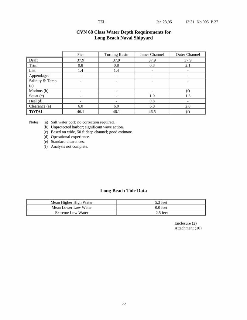
CVN 68 Class Water Depth Requirements forLong Beach Naval Shipyard
Pier Turning Basin Inner Channel Outer Channel
Draft 37.9 37.9 37.9 37.9Trim 0.8 0.8 0.8 2.1List 1.4 1.4 - -Appendages - - - -Salinity & Temp(a)
- - - -
Motions (b) - - - (f)Squat (c) - - 1.0 1.3Heel (d) - - 0.8 -Clearance (e) 6.0 6.0 6.0 2.0TOTAL 46.1 46.1 46.5 (f)
Notes: (a) Salt water port; no correction required.(b) Unprotected harbor; significant wave action.(c) Based on wide, 50 ft deep channel; good estimate.(d) Operational experience.(e) Standard clearances.(f) Analysis not complete.
Long Beach Tide Data
Mean Higher High Water 5.3 feetMean Lower Low Water 0.0 feet
Extreme Low Water -2.5 feet
Enclosure (2)Attachment (10)

36
TEL: Jan 23,95 13:31 No.005 P.28
Terminal Island Tide Access47 Foot Depth Requirement
Tide Window (hrs)
Enclosure (2)Attachment (11)

37
TEL: Jan 23,95 13:34 No.005 P.29
CVN 68 CLASS SHALLOW WATER NAVIGATION IMPROVEMENTS
Due to the deep draft of the CVN 68 Class aircraft carriers, port and shipyard access can be restricted, inorder to minimize the cost and environmental impacts of deep dredging, actual ship loading, tides, and favorableweather conditions can be used. Utilizing these factors affects operational issues such as operating schedule andcontingencies as well as ship loading and speed. Actual transit situations will vary and will involve differentcombinations of these factors. Current dredging plans will not provide unrestricted access to CVN 68 Class homeports and shipyards. To reduce the risk of grounding, it is recommended that shallow water navigation aids beimproved.
The wave and motion determination process in shallow water is complex. Wave conditions are portdependent; each port must be individually studied for an accurate assessment. The most extreme CVN motions aregenerated from seal swells originating from storms hundreds of miles away; consequently, they are difficult todetect. Waves and swells are predicted from the Fleet Numerical Oceanographic Center or observed by the crew.Waves seen in or predicted for the open ocean may not be that which are experienced at any given port. Local landand bottom effects and changes due to wind, tides, and currents are not included.
This plan improves onboard shallow water navigation aids by:(a) Providing a channel guidance system.(b) Providing real time channel condition measurement.(c) Improving ship’s draft and attitude indication.(d) Providing a load management system.
These systems and other supporting systems would be integrated as appropriate to facilitate overallfunctionality and minimize cost.
Channel Guidance System
NAVSEA has developed and tested an onboard CV Channel Guidance System (CVCGS). This systemaids in the determination of under keel clearances and the probability of grounding while operating in ports. It is aPC computer program which calculates depth requirements based on data from the ship’s force concerning loadand trim conditions. Environmental conditions are down loaded from Fleet Numerical or input from the ship'snavigator. Ship motions, under keel clearance, and probability of grounding predictions are then calculated forchannel transits. The CVCGS has been validated by ship model tests and full scale wave measurements. Thissystem will be sent to all CVs by the and of FY95.
Enclosure (3)Page 1 of 3
38
TEL: Jan 23,95 13:34 No.005 P.30
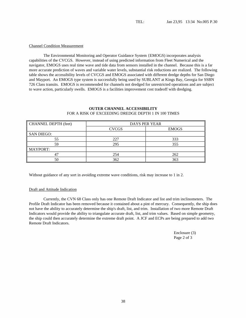
Channel Condition Measurement
The Environmental Monitoring and Operator Guidance System {EMOGS) incorporates analysiscapabilities of the CVCGS. However, instead of using predicted information from Fleet Numerical and thenavigator, EMOGS uses real time wave and tide data from sensors installed in the channel. Because this is a farmore accurate prediction of waves and variable water levels, substantial risk reductions are realized. The followingtable shows the accessibility levels of CVCGS and EMOGS associated with different dredge depths for San Diegoand Mayport. An EMOGS type system is successfully being used by SUBLANT at Kings Bay, Georgia for SSBN726 Class transits. EMOGS is recommended for channels not dredged for unrestricted operations and are subjectto wave action, particularly swells. EMOGS is a facilities improvement cost tradeoff with dredging.
OUTER CHANNEL ACCESSIBILITYFOR A RISK OF EXCEEDING DREDGE DEPTH 1 IN 100 TIMES
CHANNEL DEPTH (feet) DAYS PER YEARCVCGS EMOGS
SAN DIEGO:55 227 33359 295 355
MAYPORT:47 254 26250 362 363
Without guidance of any sort in avoiding extreme wave conditions, risk may increase to 1 in 2.
Draft and Attitude Indication
Currently, the CVN 68 Class only has one Remote Draft Indicator and list and trim inclinometers. TheProfile Draft Indicator has been removed because it contained about a pint of mercury. Consequently, the ship doesnot have the ability to accurately determine the ship's draft, list, and trim. Installation of two more Remote DraftIndicators would provide the ability to triangulate accurate draft, list, and trim values. Based on simple geometry,the ship could then accurately determine the extreme draft point. A JCF and ECPs are being prepared to add twoRemote Draft Indicators.
Enclosure (3)Page 2 of 3
39
TEL: Jan 23,95 13:36 No.005 P.31
Load Management System
The CVN 68 Class carries roughly 20,000 tons of loads (aircraft, fuel, personnel, stores, etc.). There are some 415tanks and voids and some 245 storerooms and magazines. The amount of material continuously being broughtonboard, moved, and being consumed is large. Aircraft carrier operations require the flight deck to be as level aspossible. There is a list control system to account for aircraft movement. A system similar to those used ontankers (commercial and AOEs) would provide the ship with a tool to better track and manage loads. This wouldenable the crew to minimize displacement list, and trim; thereby, minimize operational restrictions. A loadManagement system is being investigated by the CVN 76 IC effort.
Enclosure (3)Page 3 of 3
40
NOMOGRAPHS OF CVN 68 MOTION IN SHALLOW WATER
BackgroundShallow water motion transfer functions where developed for the CVN 68 class ship to aid
in predicting the ship's underkeel clearance for a variety of different entrance channels. Themotion transfer functions were validated by model tests conducted at the US Army Corps ofEngineers Waterways Experiment Station.
DescriptionThe nomographs of CVN 68 motion in shallow water were developed by combining the
shallow water motion transfer functions with a variety of wave and ship operating conditions.The waves used in calculating ship motions were developed to simulate the shallow waterenvironments. The modal wave periods ranged from 6 to 14 seconds and the significant waveheight ranged from 1 to 10 feet. The wave energy was spread using the idealized JONSWAPspectrum which is consistent with fetch limited conditions generally found in shallow water, andthe energy was spread +/- 90o to simulate shortcrested seas.
The ship operating conditions used for these nomographs were the following. The shipspeeds were 6, 10, and 14 knots which covers most transit conditions for CVN 68 class ships.The ship-to-wave heading on the nomographs are head, bow, beam, quartering and followingseas. Defining these headings, head seas are directly at the bow of the ship, bow seas are 45o offthe bow, beam seas are directly at the beam or side of the ship, quartering seas are 45o off thestern, and following seas are directly off the stem.
The vertical motion and velocity at the bow and stern of the ship is calculated for each ofthese conditions. The extreme motion expected in 100 transits is then calculated from the verticalmotion and velocity using a statistical formula generated by Ochi (1973). The largest resultingvertical motion is then used in the nomographs.
ReferenceOchi, M.K., "On Prediction of Extreme Values," Journal of Ship Research, Vol. 17 (1973).
Attachment (b)ENCLOSURE (1)

41
CVN 68 VERTICAL MOTION BY WAVE HEIGHT AND PERIODVertical Motion Represents Extreme in 100 Transits
Curves represent significant wave height in feet
HEAD SEAS
CVN 68 VERTICAL MOTION BY WAVE HEIGHT AND PERIOD

42
Vertical Motion Represents Extreme in 100 TransitsCurves represent significant wave height in feet
BOW SEAS

43
CVN 68 VERTICAL MOTION BY WAVE HEIGHT AND PERIODVertical Motion Represents Extreme in 100 Transits
Curves represent significant wave height in feet
BEAM SEAS
44
CVN 68 VERTICAL MOTION BY WAVE HEIGHT AND PERIODVertical Motion Represents Extreme in 100 Transits
Curves represent significant wave height in feet
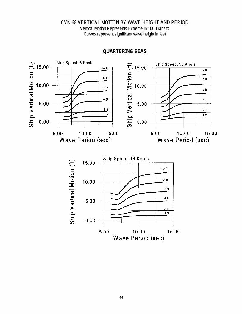
QUARTERING SEAS
45
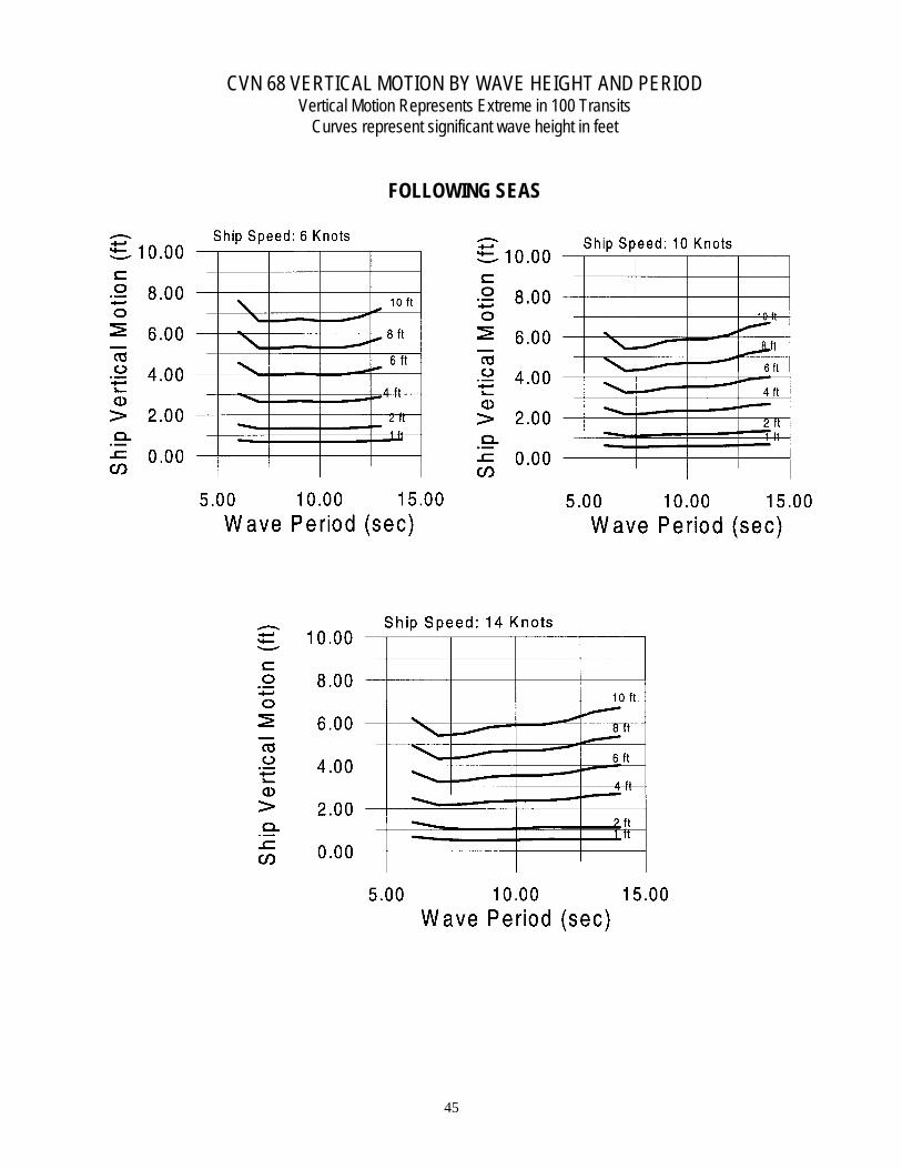
CVN 68 VERTICAL MOTION BY WAVE HEIGHT AND PERIODVertical Motion Represents Extreme in 100 Transits
Curves represent significant wave height in feet
FOLLOWING SEAS