Embed Size (px)
Citation preview
P - 414
From CMP to CRS - An Overview of Stacking Techniques of Seismic Data
Lavendra Kumar, DP Sinha, SPIC, WOFF, ONGC, Mumbai
Summary
Stacking procedures with the objective of improvement of signal to noise ratio were in use before the introduction of Common reflection point stacking introduced by Mayne in 1962. But, these techniques were problematic, at times, because they used reflections from a portion of reflectors that were too large. Hence, stacking tends to obscure the very detail of reflector which is being sought. Sorting to CMP gather and their stacking after normal moveout correction was devised by Mayne and provided a practical means of increasing multiplicity without losing the detail of the reflector. Mayne quantified the average enhancement of signal to noise ratio and showed that it is proportional to the square root of the number of signals. CMP stacking is a robust enough to handle seismic data from many different part of the world and provide reasonable good image. However, it assumes stratified earth in applying normal moveout correction and that the CMP stack is equivalent to a zero offset section. Dipping events and in regions of complex geology these assumptions are not valid and conventional processing has difficulty in delineating steeply dipping events. For a planar dipping reflector below a homogeneous overburden, reflection point dispersal take place which is also called reflection point smear. The data of a single CMP gather no longer belong to one and the same reflection point and their stacking produces degraded image. The application of dip move out (DMO) correction to the data removes the smearing and corrected CMP gather contains only reflections from a single point. However, as soon as the reflector becomes curved or the medium above the reflector is not homogeneous, the DMO correction is not exact. A residual reflection point smear will remain even after this correction. Pre-stack depth migration is carried out to correct this residual and also positioning the reflector at correct position. A number other techniques like application of higher order NMO correction and anisotropic pre-stack migration was introduced in processing to get reliable sub-surface image and improve S/N ratio. Recent developments in stacking methods include common reflection surface (CRS) stack which uses far more traces than those present in a CMP stack which leads to a better signal to noise ratio and continuity of the reflector in CRS stack. The CRS technique uses larger stacking surfaces rather than relaying on a single CMP stack location in conventional stacking processes. This leads to a larger stacking fold and results in the improvement in resolution in time and depth domain.
All these stacking techniques are reviewed and discussed in brief. A real data set belonging to onland which is characterized by low signal to noise ratio is used. The application of CRS techniques to the dataset is under progress and authors hope to get clearerimage at objective level.
Introduction:
The three principal processes of seismic data processing are: Deconvolution, Stacking and Migration (Yilmaz. O, 1987).Stacking procedures with the objective of improvement of signal to noise ratio were in use since long back. Multiplicity of receivers and sources has been used in field to form an array of vertical stacking for enhancing the signal. Stacking of CMP gathers after applying the NMO correction provided improved the S/N ratio of the data. Depending upon the type of gathers on which stacking has to be carried out, the output stacked section is referred to as the CMP /DMO/PSTM/PSDM section. The various stacking procedures are reviewed, discussed and compared by categorizing into four groups based on the type of input gathers to the stacking procedure.
1. Summing /Mixing/Vertical Stacking
2. CMP Stacking : Improving the Continuity of the reflection
3. CRP Stacking : Improving Resolution and imaging4. CRS Stacking : Stacking beyond CMP for
improving continuity and resolution
1. Summing:
Summing of the energy from number of geophones of a group to be recorded as a trace is in practice since beginning of the seismic work in the industry. The basic reason of improvement of the S/N ratio was due to out of phase summing of the shot generated coherent noise which travel in horizontal direction while reflected energy traveling almost vertical are summed in phase. The random noise is also attenuated with the square root of number of elements. Vertical stacking technique is used for low-energy sources for increasing the effective source strength or constructing the source array. Appropriate noise reduction processing
before vertically stacking the data may dramatically improve the stacked data. The vertical stacking used with various weighting schemes may also used to obtain optimum result.(Gimlin 1980, Klemperer, 1987)Trace Mixing and Decimation: Simple or weighted mixing of the adjoining traces has also been used to improve S/N ratio in certain conditions. Decimation is another techniquesused to sum a number of adjoining traces to obtain a single trace after applying partial NMO correction. Decimation techniques modified the CDP interval for further processing of data than original CDP interval in acquisition which is not the case with trace mixing which maintain the same CDP interval.Digital Group Forming: The single sensor principle of Q-Technology allows for individual detectors to be digitized and recorded separately. This enables noise attenuation filters to be optimally designed before group forming. In addition, intra-array statics may be applied to individual detectors to preserve high frequencies. DGF improves the signal to noise ratio and broadens the recorded seismic data spectrum. Geometry compensating DGF compensates for amplitude and phase variations caused by sub-optimal geometric layout, minimizing noise while preserving inherent signal characteristics.
2. CMP Stacking:
The vertical stacking/summing techniques with the objective to improve S/N ratio were problematic because they used reflections from portions of the reflectors that were too large and therefore tends to obscure the very detail which is being sought. Mayne (1962) pointed out the stacking of the CMP data after a hyperbolic correction with the NMO velocity improves the signal to noise ratio (Fig.1). CMP stacking introduced as techniques for 2D Seismic data is equally applicable to 3D data processing and has been used in seismic data processing for a long time. Stacked sections or volumes (in 3D) are standard deliverables in the industry. The by-product (stacking velocity of subsurface) of the techniques is equally valuable than the prime objective of the technique but this contribution of the technique is not properly recognized in industry. Subsequent improvement in the stacking technique has provided accurate information of the sub-surface and helps in interpretation.
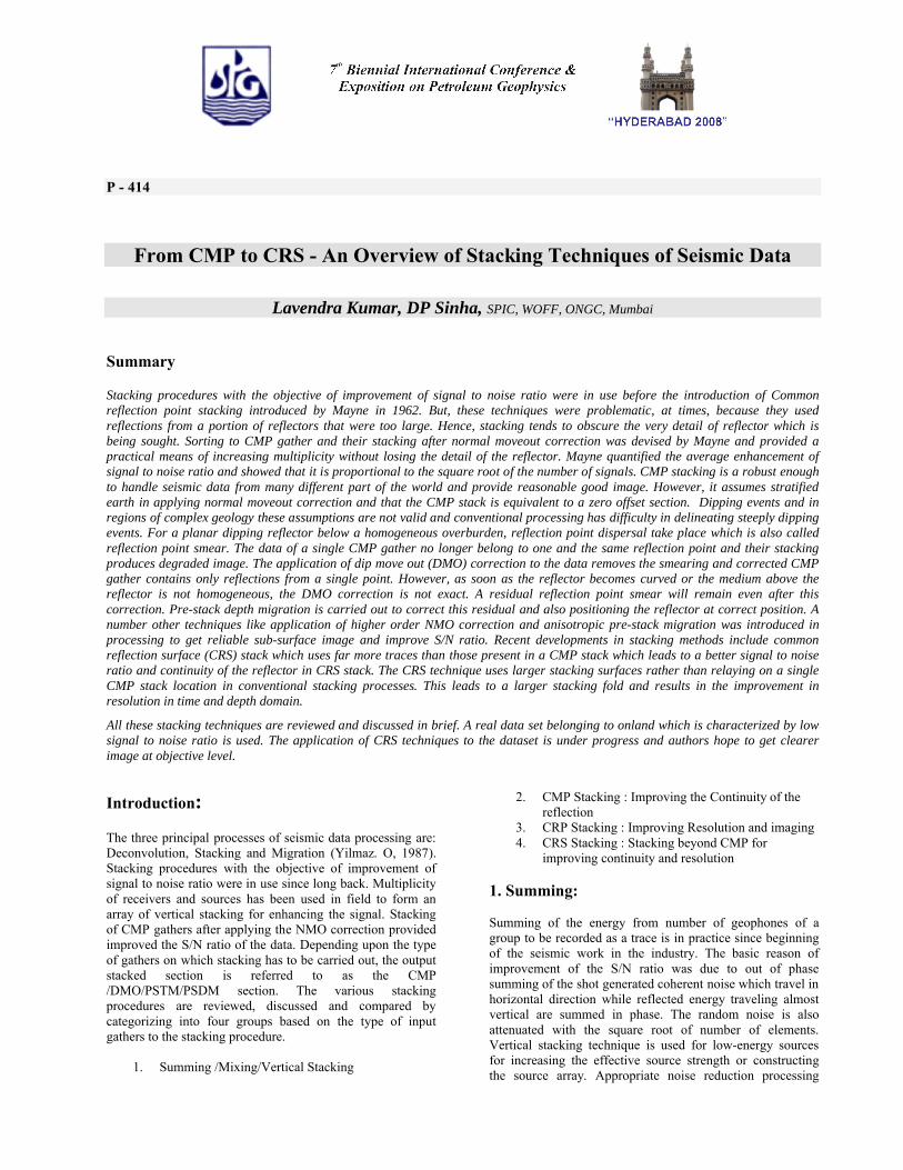
Fig . 1: CMP gather for horizontal reflector
Fig .2: CMP gather for Dipping Reflector-Reflection Point Dispersal
CMP stacking is the powerful tool for the enhancement of S/N ratio by stacking of in-phase signal and out of phase stacking of random as well as coherent noises recorded in traces having different offset. The improvement in the S/N ratio depends upon the number of traces stacked.This technique, designed for 2D surveys, was basically for data with constant foldage and regular offset distribution at constant interval within a CDP gather along whole line. However, restrictions in the field or near surface problems causes missing offsets resulting poor stack. Sub-surface conditions like poor impedance contrast, faulting/thrusting, scattering/diffractions, presence of high velocity layer above target and other geological complexities may also degrade the quality. Stacking methods that allow non-hyperbolic moveout at large offset caused by anisotropy. However, the primary reflection time is hyperbolic when seismic data is acquired over a horizontal reflector below a homogeneous overburden.For a dipping reflector, the reflection point dispersal degradesthe stacked quality (Fig.2).
3. CRP Stacking:
CMP stacking devised to increase the multiplicity was actually thought “Common Reflection Point” gathers than CMP gathers. These two concepts are equivalent only for a horizontal reflector below an overburden with purely vertical velocity variations. For a planar dipping reflector below a homogeneous overburden, there is smearing of reflection point called reflection point dispersal. All the traces of a CMP gather are now no longer belong to one and the same reflection point. Application of dip moveout correction (DMO) to the data makes the gathers (generally called DMO gathers) which contains reflections from a single reflection point (Fig 3). The stacking of such gathers provides the DMO stack and improves the resolution of the obtained image. ( Deregowski SM, 1986, Yilmaz O and Claerbout JF, 1980).However, as soon as the reflector becomes curved or the overburden becomes inhomogeneous, the DMO is not exact and a residual reflection point smear still will remain. This effect grows the stronger with the reflector curvature and / or the medium in-homogeneities in the overburden. Thus DMO correction corrects only that part of the reflection point smear which is due to reflector dip. It will not correct for the
smearing caused by the reflector curvature or inhomogeneity in overburden.
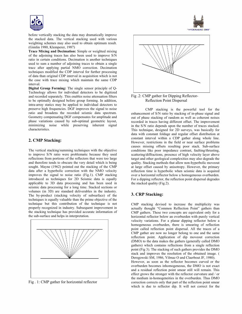
Fig. 3: DMO gather: Reflection Point dispersal is corrected by DMO correction but positioning is to be corrected by Post stack Migration.
Fig 4: Reflection Point dispersal due to Lateral velocity variation above reflector will not be corrected by DMO or PSTM.
Pre-stack Migration (PSTM and PSDM): Pre-stack migrations also transforms the CMP gathers into CRP gathers. Pre-stack time migration of data also removes the reflection point dispersal of the data pertaining to the dipping reflector but not due to lateral velocity variation. The prestack depth migration is carried out to remove this dispersal and correcting the position. (Fig5) Ning Guo 2002)
Fig. 5: Image gathers after PSDM (Positional correction is not depicted here)
4. CRS Stacking:
The average theoretical enhancement of signal to noise ratio obtained with CMP stacking is proportional to the square root of the number of signals/traces stacked. The CRS technique uses larger stacking surfaces rather than relaying on a single CMP stack location in conventional stacking processes. This leads to a larger stacking fold and results in the improvement in resolution in time and depth domain. The CRS stackcorresponds to subsurface model, where reflector elements-the common reflection surface- are defined by their subsurface location, reflector curvature and dip. The increased validity of the CRS reflection time approximation is provided by three independent parameters for 2D seismic data, whereas only one parameter is required for the conventional NMO stack technique, i.e. the stacking velocity. The three parameters consist of an emergence angle, and two radii of wavefield curvature. (Fig 6 and 7 Mann J1999)The parameters triplet (α, RNIP, RN) is determined automatically for each point (X, T) in the zero offset stack section. The optimum values are characterized by a semblance maximum along the associated stacking surface. In order to avoid a time consuming three dimensional search for the global semblance maximum, three separate searches are carried out in sub-volumes of the entire dataset, i.e. in CMP gathers and in a preliminary stack section. The obtained preliminary parameter estimates may subsequently be refined by a true 3D search, which is confined to the vicinity of the estimates.
The CRS parameters also allow to derive a background velocity model, as it is used for the conventional NMO stack. Vice versa, a scaled stacking velocity field from conventional NMO analysis may be used as a minimum velocity limit for the automatic CRS parameter search, in order to avoid the stacking of multiples.The CRS stack method (Jager et. al. 2001) is a highly automated imaging process. It can be seen as a generalization of high – density stacking velocity analysis and incorporates neighboring common midpoint gathers. In contrast to conventional stacking approaches which provide only one parameter (i.e stacking velocity), the CRS stack provides an entire set of stacking parameters, the so called kinematic wavefield attributes. These attributes locally characterize the reflection events in the pre-stack data in the vicinity of the respective stationary points.
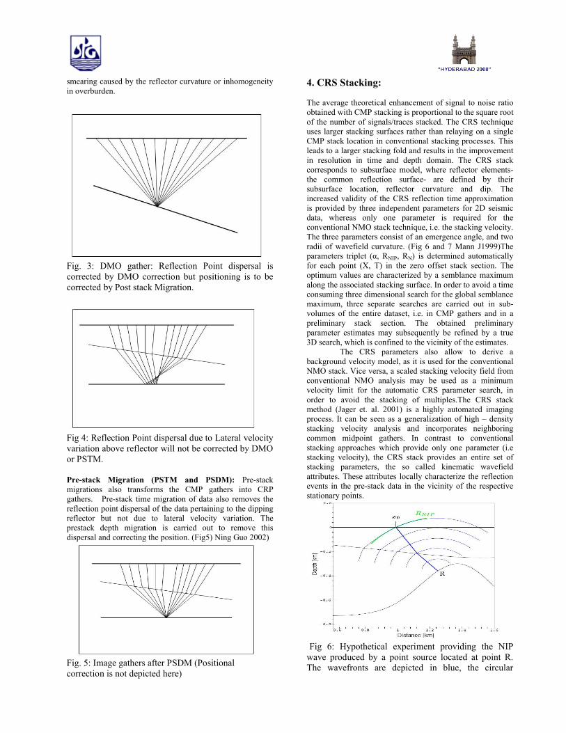
Fig 6: Hypothetical experiment providing the NIP
wave produced by a point source located at point R. The wavefronts are depicted in blue, the circular
approximation in green. The normal incidence ray (bold blue line ) at point R. ( After Mann 1999)
Fig 7: Hypothetical experiment providing the Normal wave generated by an exploding reflector experiment.The wavefronts are depicted in blue, the circular approximation in red. The normal incidence ray (bold blue line) at point R. ( After Mann 1999).Basics of CRS Stack: The CRS method is based on a second order approximation of the kinetic reflection response of an arbitrary curved reflector segment with inhomogeneous overburden. In the 2D case, this approximation can be entirely expressed in terms of three stacking parameters, namely the emergence angle α of the central ray and the radii RNIP and RN of wavefront curvatures of two hypothetical waves, the so called NIP and normal wave, respectively, respectively (Hubral, 1999) Table 1. The commonly used hyperbolic approximation is given in Schleicher et.al.(1993). As in conventional stacking velocity analysis, the optimum wavefield attributes for each zero offset location are determined by coherence analysis in the pre-stack data. However, this analysis is carried out with a spatial operator in a multi-dimensional parameter domain. This finally yields entire sections of the wavefield attributes α, RNIP, RN, as well as a coherence section.
Table 1: Stacking Parameters of CRS stackParameter Definitionα Emergence angle at the surface of array
normal to the subsurface reflectorRNIP Radius of curvature, that can be
simulated by the wave from a point source located at the Normal Incidence Point (NIP) on the subsurface reflector
RN radius of curvature, that can be simulated by the wave from an exploding reflector experiment at the considered subsurface reflector
Application of CRS method:The CRS method has proved to be a valid
alternative to conventional NMO/DMO processing. Numerous application examples demonstrate the increase in resolution by this technique. The superior signal to noise ratio and reflector continuity are supplemented by an enhanced
imaging of structural details and dipping events. The zero offset section from multi-coverage seismic reflection data is obtained without explicit knowledge of the macro-velocity model i.e. in a data driven way. The application of a macro-model independent approach in obtaining improved continuity with enhanced imaging of structural details and dipping elements have made this method as a routine technique in time processing workflows. Moreover, post stack depth migration of CRS time domain stacks are reported to be superior to pre-stack depth migration images.( ). Hence, CRS processing represents an alternative for depth processing in areas where pre-stack depth migration fails to enhance structural resolution.
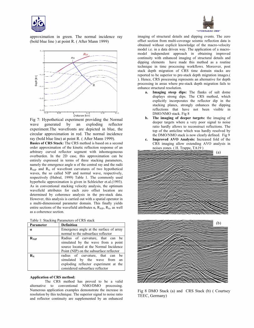
a. Imaging steep dips: The flanks of salt dome displays strong dips. The CRS method, which explicitly incorporates the reflector dip in the stacking planes, strongly enhances the dipping reflections that have not been visible in DMO/NMO stack. Fig 8
b. The imaging of deeper targets: the imaging ofdeeper targets where a very poor signal to noise ratio hardly allows to reconstruct reflections. The top of the anticline which was hardly resolved by the DMO/NMO stack is now clearly defined. Fig 9
c. Improved AVO Analysis: Increased fold of the CRS imaging allow extending AVO analysis in noises zones. ( H. Trappe, TA19 )
Fig 8 DMO Stack (a) and CRS Stack (b) ( Courtsey TEEC, Germany)
(a)
(b)

Real Data Set:
The dataset pertain to the onland area of KG Basin. Presence of trap (high velocity layer) at shallower level restricts penetration of energy and therefore result poor signal to noise ratio at deeper level. Noise due to cultural activities further degrades the image quality especially at deeper level. The data was acquired with the objective of improving deeper event for exploring prospectivity of Cretaceous sediments.The 75 fold data was acquired with 20 mts group interval and having maximum far offset more than 8 kms with asymmetrical geometry. Even after using the relatively higher charge size, the conventional processing provided the poorer image at deeper level (Fig. 10). Various techniques like trace mixing, trace decimation, application higher order NMO and processing with lower frequency data were tried to improve the image but in vain. This data is under process for CRS stack. It is expected that a good image will be obtained at deeper level. A improvement in quality is found by the stacking beyond the CMP section shown in figure 8. Improved image at 4 sec is obtained when data is stacked after the borrowing the traces from adjoining CDP points to increase the fold of stack.
Fig 9: Pre-SDM stack (a) and Post stack depth migration of CRS stack (b)
Fig 10: CMP Stack (a) and Stacking beyond CMP (b)
Conclusion
Multiplicity of detectors and source dominated in the industry in the initial period to industry for vertical stacking of the data for the enhancement of signal to noise ration. Horizontal stacking of the CMP gathers provided a big step in the improvement of the S/N ratio and reliable estimate of the sub-surface velocity could be possible due to this technique. DMO and Pre-stack migrations improved the imagingcapability of the technique and velocity information could be obtained more reliably. Stacking is now moving from a point to the surface and many cases have been reported where post stack migration of CRS stack provides better imaging then PreSDM image especially in steep dip, poor S/N ratio areas. CRS stack maximum information form the data in bringing out the sub-surface image.
Acknowledgement
Authors are grateful to Director (Exploration), Oil and Natural Gas Corporation Limited, India for providing the necessary facilities to carry out this work and permission to publish the work.Views expressed in this paper are that of the authors only and may not necessarily be of ONGC.
(a)
(b)
(a)
(b)
Reference
1. Ning Guo and Stuart Fagin, 2002, Becoming effective velocity model builders and depth imagers, Part 1- the basics of prestack depth Migration, The Leading Edge, December, 2002.
2. Hubral, P 1999, Seismic Illumination, The Leading Edge, November, 2001.
3. Gimlin D. R. and Smith J.W., 1980, A comparison of seismic tarce summing technique- Geophysics,June 1980.
4. Klemperer S. L. 1987, Seismic noise-reduction techniques for use with vertical stacking: An empirical comparison: Geophysics, March 1987.
5. H Trappe, G Gierse, J Prussmann,, Improved resolution in time and depth processing by macro-model independent CRS stacking; Technical Article No. 15, TEEC
6. Rainer Jager, Jurgen Mann, German Hocht and Peter Hubral,2001, Common Reflection Surface stack: Image and Attributes, Geophysics2001
7. J Mann et al 1999, Applications of Common Reflection Surface Stack,SEG Expanded Abstract,1999
8. T Hertweck et. al. 2007, Stacking Beyond CMP TLE 2007
9. Deregowski, SM 1986, What is DMO, First Break 4, EAGE,1986
10. Yilmaz. O and Claerbout JF, 1980, Pre-stack Partial Migration, Geophysics 45, 1980
11. Yilmaz. O, 1987, Seismic Data Processing, SEG, Tulsa,1987
12. H. Trappe, et al , Improved AVO Analysis By Common Reflection Surface (CRS) Technology, TA 19, TEEC Germany.
13. WH Mayne, 1962, Common Reflection Point Horizontal Data Stacking Techniques, Geophysics, 1962