Embed Size (px)
Citation preview
International Journal of Rotating Machinery2000, Vol. 6, No. 1, pp. 67-78
Reprints available directly from the publisherPhotocopying permitted by license only
2000 OPA (Overseas Publishers Association) N.V.Published by license under
the Gordon and Breach Science
Publishers imprint.Printed in Malaysia.
Vibration Criteria Considered from Case Studies of ActiveMagnetic Bearing Equipped Rotating Machines*
OSAMI MATSUSHITAa’t, YOUICHI KANEMITSUb, TAKAO AZUMA and YASUO FUKUSHIMAd
Department of Mechanical Engineering, The National Defense Academy, 1-10-20 Hashirimizu, Yokosuka, Kanagawa, Japan 239,"l)Faculty of Mechanical Engineering, Kyushu University, 6-10-1 Hakozaki, Higashi-ku, Fukuoka, Japan 812-21,
lshikawashima Noise Control Ltd., Ryuseido Okubo Bldg. 1-15-18 Hyakunin-machi, Shinjyuku, Tokyo, Japan 169;’Compressor Design Department, Tsuchiura works, Hitachi Ltd., 603 Kandatsu-machi, Tsuchiurashi, Japan 300
(Received 23 April 1998," In finalform 6 October 1998)
The main part of turbo machinery is conventionally supported by oil film lubricated bearings.The rotor vibrations can be suppressed within low levels as to satisfy vibration criteria, e.g.,ISO standards for general rotors and API 617 for process compressors. Recently, thesophisticated advantages of the active magnetic bearing (AMB) have been increasing thenumber of applications to industrial rotors. The AMB vibration control design requiresthe weak support which induces inevitably large vibration amplitude, though it is normal forAMB itself. Vibration criteria indicated by present standards are thus too strict for AMBequipped rotors. The difference of the bearing dynamic characteristics between the oil filmlubricated bearing and the AMB compels us to prepare a new ISO standard whichrecommends the acceptance of higher vibration levels for AMB operation.
In this paper, a case study was executed concerning AMB equipped LP and HPcompressors experiencing long-term operation with no major trouble since December, 1992.The rotating rated speed, 10900 rpm, is beyond the first bending critical speed with 5300 kWof power. The average value of the rotor vibration was about 50 #mpp in the site operation.By reviewing the rotor design concept and field data of these AMB equipped machines, newvibration criteria are considered for a proposal of ISO standardization.
Keywords." Active magnetic bearing, Oil film lubricated bearing, Compressor, Critical speed layout,Vibration evaluation criteria, Flexible rotor, Control
INTRODUCTION
A few types of active magnetic bearing (AMB)equipped rotating machinery are currently beingimplemented successfully in the commercial business
market since the development phase of the AMBborne rotor was completed. Some successful exam-ples include turbo-molecular pumps, expandersin chemical plants, spindles in machine toolsand centrifugal compressors in turbo machinery.
This paper was originally presented at ISROMAC-7.Correponding author. Tel.: 0468-41-3810, Extn. 2326. Fax: 0468-44-5900. E-mail" [email protected].
67
68 O. MATSUSHITA et al.
The new concept of AMB is indeed welcome,thanks to its features of being contact free,maintenance free and without mechanical losses.A typical system supported by the AMB is
illustrated in Fig. 1. AMBs are located at both endsof the shaft including adjacent placements ofdisplacement sensors and emergency (auxiliary)ball bearings. The control network for driving theAMB device is shown in Fig. 2. As shown in thesefigures, each displacement sensor detects the shaftposition at bearing portions and its signal is fedback to the compensator. The deviation from thebearing center is put into the PID (Proportional,Integral and Differential actions)controller. Thecontroller drives the power amplifiers to sup.ply thecoil current and to generate the magnetic force forthe levitation and vibration control. Instead ofPID,many modern control laws, e.g., LQ and H-infinity,are being investigated for this servo-feedbackcontrol design.The AMB dynamic characteristics is governed by
the controller transfer function. An example of thetransfer function of a PID controller is illustrated inthe Bode diagram of Fig. 3. The phase leadfrequency domain of the phase curve, e.g., 0.1-10
ROTOR AMB
(non-dimension frequency/the first free-freebending frequency), can provide positive dampingto the rotor system, but negative damping in otherfrequency domains. In this example, the vibrationsof the rigid modes and the first bending mode arecovered by the positive damping domain.Compared with conventional oil film lubricated
bearings having only positive damping, it can besaid that the AMB provides low bearing forces dueto limits of the magnetic density. Therefore,concerning bearing support stiffness, the former isstrong, and the latter weak. Another opinion mightsay that the former is too strong, but the latter ispreferable.The main part of turbo machinery is still
supported by oil film lubricated bearings. The rotorvibrations can be suppressed within low levelsthanks to its stiff support. Vibration evaluationsapplied to the current type of rotating machines arecovered by ISO standards (ISO 7919/1-5) (1996).These ISO standards consequently require lowlimits for a permissible vibration level. On the otherhand, it is hard to suppress AMB rotor vibrationswithin such low levels due to the feature of its weakbearing stiffness. Furthermore, the AMB designrequires the placement of the AMB at the locationof the vibrating portions for effective vibrationcontrol. Large vibration magnitude is thus inevi-tably measured in spite of being normal.
This difference between AMB and oil filmbearing dynamics induces a potential conflict
FIGURE Active magnetic bearing equipped rotor system.
Rotaionl OPTIONAL CONTROL
’ with ROTATION _SENSORpu|sel ABS N-cross FF Excitation etc POWER-- i "
I-I AMP, I /
FIGURE 2 AMB control network layout including options:Optional controls work during rotation with inputting therotational pulse signal.
100
70
Z(.9 60
5O
Rigid Modes I/st Bending
0.01II I1 tl I11 .llil
0.1 O0FREQUENCY First Bending Frequency
180
120
60
-60
-120
-180
FIGURE 3 AMB controller transfer function: Note that thepositive and negative values of the phase curve correspond tothe phase lead and lag, i.e., the positive and negative dampingfactors, respectively.
VIBRATION CRITERIA 69
between customers and manufacturers. In the caseof process compressors equipped with AMBs, a
customer requires a manufacturer to comply withthe API 617 (1995) regulation which provides forlow vibration limits in the same manner as if thecompressor were supported by oil film lubricatedbearings, though it is actually supported by AMBs.These present limits are too strict for the AMBrotor manufacturing side.As mentioned above, we need to prepare new ISO
standards which will accept the relatively highvibration limits in accordance to the requirementof proper AMB design and operation. This paperproposes new vibration criteria for AMB equippedrotor systems in order to ultimately solve thiscontradiction.
been recently introduced this type of turbomachinery. The consideration of the differencesbetween the bearing dynamic characteristics ofboth types, i.e., the strong support of the oil filmbearing and the weak support of the AMB, are notconsidered in these series. So far each vibrationcriteria prepared in ISO and/or AP! standardsgovern uniformly oil film bearing equipped turbomachinery. Unfortunately, there are no vibrationstandards concerning AMB equipped turbomachines.
Because of these concerns, Japanese expertshave proposed international standardization forAMB related technology to the ISO TC108/SC2.The objectives of this standardization are as
follows:
REQUIREMENTS FOR ISO TC108 ONRELATED VIBRATION REGULATIONS
A set of ISO standards on rotor vibration regula-tions for turbo machines is given in ISO 7919 series.ISO 7919: Mechanical vibration of non-recipro-cating machines: measurement on rotating shaftand evaluation criteria
Part 1: General guidelines,Part 2: Large land-based steam turbine generator
sets,Part 3: Coupled industrial machines,Part 4: Gas turbine sets,Part 5: Machine sets in hydraulic power generating
and pumping plants.
ISO TC108 (Mechanical Vibration and Shock)/SC2(Measurement and Evaluation of MechanicalVibration and Shock as Applied to Machines,Vehicle and Structures)/WG1 (Vibration ofMachines) has been developing the ISO 7919 serieswhich specifically covers the vibration of turbomachinery; turbines, generators, compressors,pumps, and so on.When considering centrifugal compressors, these
rotors are conventionally supported by oil filmbearings, e.g., tilting pad bearings. The AMB has
(1) to define AMB terminology for promotingmutual understanding for the relevant people,
(2) to resolve conflicts between venders and users
with proper designs and operations,(3) to provide vibration criteria to simplify
contract concerns, commissions, etc.,(4) to promote a design, operation and mainte-
nance guides for AMB equipped rotors,(5) to accelerate low cost production and wide-
spread applications.
ISO agreed with the necessity of this standardiza-tion and organized a new WG7 on Vibration ofActive Magnetic Bearing Equipped RotatingMachines. This paper will be contributed for a
working draft ofWG7 which covers AMB rigid andflexible rotors.
This paper concerns steady state vibrationsmeasured during normal continuous operation,but not resonance vibrations for passing criticalspeeds. Resonance vibrations are stated in ISO10814 titled "Mechanical Vibration Susceptibilityand Sensitivity of Machines to Unbalance."According to this standard, rotor resonance vibra-tions are evaluated by the modal sensitivity, so
called Q-value. This Q-value evaluation was stan-dardized in reference to Balda (1975) and Shirakiand Kanki (1979).
70 O. MATSUSHITA et al.
CASE STUDIES
Active Magnetic Bearing Applications toCentrifugal Compressor
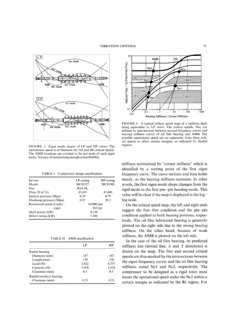
Fukushima et al. (1994) showed thatAMB equippedcentrifugal compressors were manufactured byHitachi Ltd., Japan, and installed at a refinery plantin Okinawa Sekiyu Seisei Co., Ltd. as the end userunder the project contract of Idemitsu EngineeringCo., Ltd. and Chiyoda Corporation. As shown inFig. 4, this turbo machine is a train system whichincludes a turbine and high and low pressure com-pressors, noted (HP) and (LP), respectively. Theserotors are connected with flexible couplings. TheseLP and HP compressors are supported by AMBs.This turbine rotor is conventionally supported by oilfilm bearings. The rotor configurations of the LPand HP compressors are drawn in Fig. 5, includ-ing eigen mode shapes obtained by average values ofthe AMB supporting stiffness. The LP and HPcompressors have 7 and 8 stage impellers with therotor weight of 780 and 930kg, respectively. Asshown in Fig. 5, the control theory demands that theAMB actuator locations should be on such vibratingportion of eigen mode. This demand opposes thedesire for low levels of resultant vibrations.
The design specifications for the processcompressor is shown in Table I. The rated speed is10,900 rpm- 182 rps with the nominal shaft power4120kW. The specification with respect to theAMB is shown in Table II. These radial AMBsare specified by L/D:O.98, C/R:6.8/1000 withC-one side clearance=0.5mm per the AMBjournal diameter= 147mm. It is noted that theclearance of the auxiliary bearing is set by abouthalf the AMB clearance for protecting emergencycontacts of the AMB itself.
Comparison Between Oil Film Bearings andAMBs on Critical Speed Map
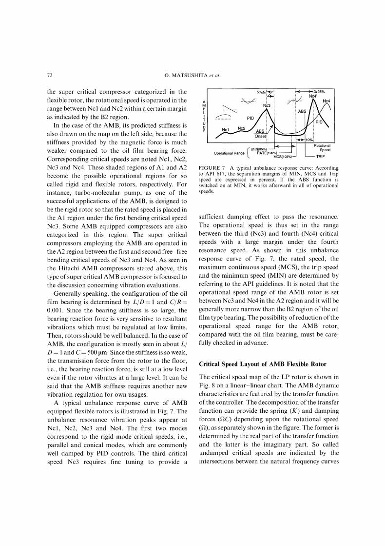
One of the most important aspects for designingprocess compressors is the critical speed map. Inorder to better understand rotordynamics incomparison with oil film. bearings and AMBs, a
uniform shaft simplified from actual rotors isselected, having the equivalent diameter of150mm and the same length of the LP as shownin Fig. 5. The critical speed map is thus calculatedfor the uniform shaft, as shown on a non-dimen-sional chart of Fig. 6. The vertical axis is the naturalfrequency normalized by the first free-free bendingmode. The horizontal axis indicates the bearing
Turbine HP Casing LP Casing
]’__ff 9811--[L-7_ xBCHS08 MCH527
FIGURE 4 Train of AMB equipped compressor.
VIBRATION CRITERIA 71
4th mode
1st mode
4th mode
FIGURE 5 Eigen mode shapes of LP and IHP rotors: Theoperational speed is set between the 3rd and 4th critical speeds.The AMB locations are avoided to be not node of each eigenmode, because of maintaining enough controllability.
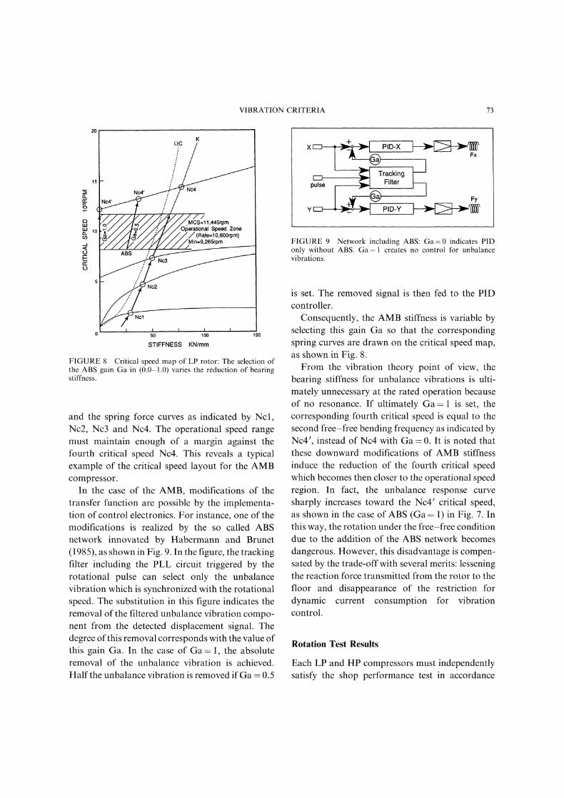
TABLE Compressor design specification
ServiceModelGasFlow (N m3/h)Suction pressure (Mpa)Discharge pressure (Mpa)Rotational speed (1/rain)
(rps)Shaft power (kW)Driver rating (kW)
LP casingMCH527Rich H243,6910.330.91
10,900 rpm182 rps
4,1205,300
HP casingMCH508
43,4860.7920.3
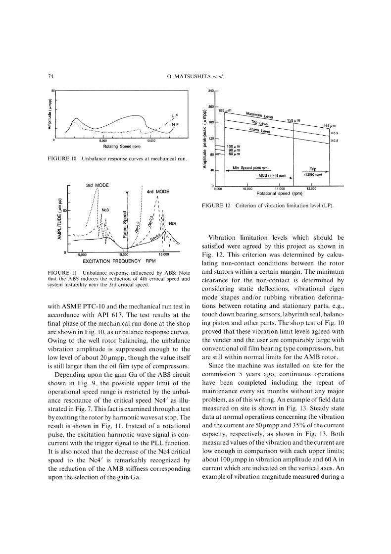
TABLE II AMB specification
LIP HP
Radial bearingDiameter (mm) 147 147Length (mm) 150 150Load (N) 3,822 4,557Capacity (N) 1,034 1,034Clearance (mm) 0.5 0.5
Radial auxiliary bearingClearance (ram) 0.23 0.23
AMB
Nc
0.1o.1
O.OlBearing Stiffness Corner Stiffness
lO lOO lOOO
FIGURE 6 A typical critical speed map of a uniform shaftbeing equivalent to LP rotor: The critical speeds, Nci, aredefined by intersections between natural frequency curves andbearing stiffness curves of oil film bearing and AMB. Thepossible operational speed are set separately from these criti-cal speeds to allow certain margins, as indicated by shadedregions.
stiffness normalized by "corner stiffness" which isidentified by a veering point of the first eigenfrequency curve. The curve inclines and then holdssteady, as the bearing stiffness increases. In otherwords, the first eigen mode shape changes from therigid mode to the first pin-pin bending mode. Thisvalue will be clear if the map is displayed in the log-log scale.On the critical speed map, the left and right ends
suggest the free-free condition and the pin-pincondition applied to both bearing portions, respec-tively. The oil film lubricated bearing is generallyplotted on the right side due to the strong bearingstiffness. On the other hand, because of weakstiffness, the AMB is plotted on the left side.
In the case of the oil film bearing, its predictedstiffness line (dotted line, X and Y directions) isdrawn on the map. The first and second criticalspeeds are thus marked by the intersections betweenthe eigen frequency curves and the oil film bearingstiffness, noted Ncl and Nc2, respectively. Thecompressor to be designed as a rigid rotor mustlocate the operational speed under the Nc within a
certain margin as indicated by the B1 region. For
72 O. MATSUSHITA et al.
the super critical compressor categorized in theflexible rotor, the rotational speed is operated in therange between Nc and Nc2 within a certain marginas indicated by the B2 region.
In the case of the AMB, its predicted stiffness isalso drawn on the map on the left side, because thestiffness provided by the magnetic force is muchweaker compared to the oil film bearing force.Corresponding critical speeds are noted Ncl, Nc2,Nc3 and Nc4. These shaded regions of A1 and A2become the possible operational regions for socalled rigid and flexible rotors, respectively. Forinstance, turbo-molecular pump, as one of thesuccessful applications of the AMB, is designed tobe the rigid rotor so that the rated speed is placed inthe A1 region under the first bending critical speedNc3. Some AMB equipped compressors are alsocategorized in this region. The super criticalcompressors employing the AMB are operated inthe A2 region between the first and second free-freebending critical speeds of Nc3 and Nc4. As seen inthe Hitachi AMB compressors stated above, thistype of super critical AMB compressor is focused tothe discussion concerning vibration evaluations.
Generally speaking, the configuration of the oilfilm bearing is determined by LID and C/R--0.001. Since the bearing stiffness is so large, thebearing reaction force is very sensitive to resultantvibrations which must be regulated at low limits.Then, rotors should be well balanced. In the case ofAMB, the configuration is mostly seen in about L/D and C 500 m. Since the stiffness is so weak,the transmission force from the rotor to the floor,i.e., the bearing reaction force, is still at a low leveleven if the rotor vibrates at a large level. It can besaid that the AMB stiffness requires another newvibration regulation for own usages.A typical unbalance response curve of AMB
equipped flexible rotors is illustrated in Fig. 7. Theunbalance resonance vibration peaks appear atNcl, Nc2, Nc3 and Nc4. The first two modescorrespond to the rigid mode critical speeds, i.e.,parallel and conical modes, which are commonlywell damped by PID controls. The third criticalspeed Nc3 requires fine tuning to provide a
Nb3
I’- MIN(85%)Operational Range . RATE(10o%)
L MCS(105%)
>--25%N(4’
RotationalSpeed
TRIP
FIGURE 7 A typical unbalance response curve: Accordingto API 617, the separation margins of MIN, MCS and Tripspeed are expressed in percent. If the ABS function isswitched on at MIN, it works afterward in all of operationalspeeds.
sufficient damping effect to pass the resonance.The operational speed is thus set in the rangebetween the third (Nc3) and fourth (Nc4) criticalspeeds with a large margin under the fourthresonance speed. As shown in this unbalanceresponse curve of Fig. 7, the rated speed, themaximum continuous speed (MCS), the trip speedand the minimum speed (MIN) are determined byreferring to the API guidelines. It is noted that theoperational speed range of the AMB rotor is setbetween Nc3 and Nc4 in the A2 region and it will begenerally more narrow than the B2 region of the oilfilm type bearing. The possibility ofreduction oftheoperational speed range for the AMB rotor,compared with the oil film bearing, must be care-fully checked in advance.
Critical Speed Layout of AMB Flexible Rotor
The critical speed map of the LP rotor is shown inFig. 8 on a linear-linear chart. The AMB dynamiccharacteristics are featured by the transfer functionof the controller. The decomposition of the transferfunction can provide the spring (K) and dampingforces (C) depending upon the rotational speed(f), as separately shown in the figure. The former isdetermined by the real part of the transfer functionand the latter is the imaginary part. So calledundamped critical speeds are indicated by theintersections between the natural frequency curves
VIBRATION CRITERIA 73
FIGURE 8 Critical speed map of LP rotor: The selection ofthe ABS gain Ga in (0.0-1.0) varies the reduction of bearingstiffness.
and the spring force curves as indicated by Ncl,Nc2, Nc3 and Nc4. The operational speed rangemust maintain enough of a margin against thefourth critical speed Nc4. This reveals a typicalexample of the critical speed layout for the AMBcompressor.
In the case of the AMB, modifications of thetransfer function are possible by the implementa-tion of control electronics. For instance, one of themodifications is realized by the so called ABSnetwork innovated by Habermann and Brunet(1985), as shown in Fig. 9. In the figure, the trackingfilter including the PLL circuit triggered by therotational pulse can select only the unbalancevibration which is synchronized with the rotationalspeed. The substitution in this figure indicates theremoval of the filtered unbalance vibration compo-nent from the detected displacement signal. Thedegree ofthis removal corresponds with the value ofthis gain Ga. In the case of Ga--1, the absoluteremoval of the unbalance vibration is achieved.Half the unbalance vibration is removed if Ga 0.5
r--i,, Tracking
;E’’FilterFy
PID-Y
FIGURE 9 Network including ABS: Ga=0 indicates PIDonly without ABS. Ga= creates no control for unbalancevibrations.
is set. The removed signal is then fed to the PIDcontroller.
Consequently, the AMB stiffness is variable byselecting this gain Ga so that the correspondingspring curves are drawn on the critical speed map,as shown in Fig. 8.From the vibration theory point of view, the
bearing stiffness for unbalance vibrations is ulti-mately unnecessary at the rated operation becauseof no resonance. If ultimately Ga is set, thecorresponding fourth critical speed is equal to thesecond free-free bending frequency as indicated byNc4 t, instead of Nc4 with Ga 0. It is noted thatthese downward modifications of AMB stiffnessinduce the reduction of the fourth critical speedwhich becomes then closer to the operational speedregion. In fact, the unbalance response curvesharply increases toward the Nc4’ critical speed,as shown in the case of ABS (Ga 1) in Fig. 7. Inthis way, the rotation under the free-free conditiondue to the addition of the ABS network becomesdangerous. However, this disadvantage is compen-sated by the trade-off with several merits: lesseningthe reaction force transmitted from the rotor to thefloor and disappearance of the restriction fordynamic current consumption for vibrationcontrol.
Rotation Test Results
Each LP and HP compressors must independentlysatisfy the shop performance test in accordance
74 O. MATSUSHITA et al.
LP
5,000 10,000
Rotating Speed (rprn)
FIGURE 10 Unbalance response curves at mechanical run.
Eso
3rd MODE
"" 4rd MODE
It
NC3
/ ",.x,i
5,000 10,000 15,000
EXCITATION FREQUENCY RPM
FIGURE 11 Unbalance response influenced by ABS: Notethat the ABS induces the reduction of 4th critical speed andsystem instability near the 3rd critical speed.
with ASME PTC-10 and the mechanical run test inaccordance with API 617. The test results at thefinal phase of the mechanical run done at the shopare shown in Fig. 10, as unbalance response curves.
Owing to the well rotor balancing, the unbalancevibration amplitude is suppressed enough to thelow level of about 20 lampp, though the value itselfis still larger than the oil film type of compressors.Depending upon the gain Ga of the ABS circuit
shown in Fig. 9, the possible upper limit of theoperational speed range is restricted by the unbal-ance resonance of the critical speed Nc41 as illu-strated in Fig. 7. This fact is examined through a testby exciting the rotor by harmonic waves at stop. Theresult is shown in Fig. 11. Instead of a rotationalpulse, the excitation harmonic wave signal is con-
current with the trigger signal to the PLL function.It is also noted that the decrease of the Nc4 criticalspeed to the Nc4’ is remarkably recognized bythe reduction of the AMB stiffness correspondingupon the selection of the gain Ga.
240
200
160
120
60
Min Speed (9265 rpm)40
MCS (11445 rpm)
9,000 10,000 11,000 12,000
Rotational speed (rpm)
185 um
8FmX0.9__....... X0.8
100/ m90,um80,=m
Trip(12590 rpm)
FIGURE 12 Criterion of vibration limitation level (LP).
Vibration limitation levels which should besatisfied were agreed by this project as shown inFig. 12. This criterion was determined by calcu-lating non-contact conditions between the rotorand stators within a certain margin. The minimumclearance for the non-contact is determined byconsidering static deflections, vibrational eigenmode shapes and/or rubbing vibration deforma-tions between rotating and stationary parts, e.g.,touch down bearing, sensors, labyrinth seal, balanc-ing piston and other parts. The shop test of Fig. 10proved that these vibration limit levels agreed withthe vender and the user are comparably large withconventional oil film bearing type compressors, butare still within normal limits for the AMB rotor.
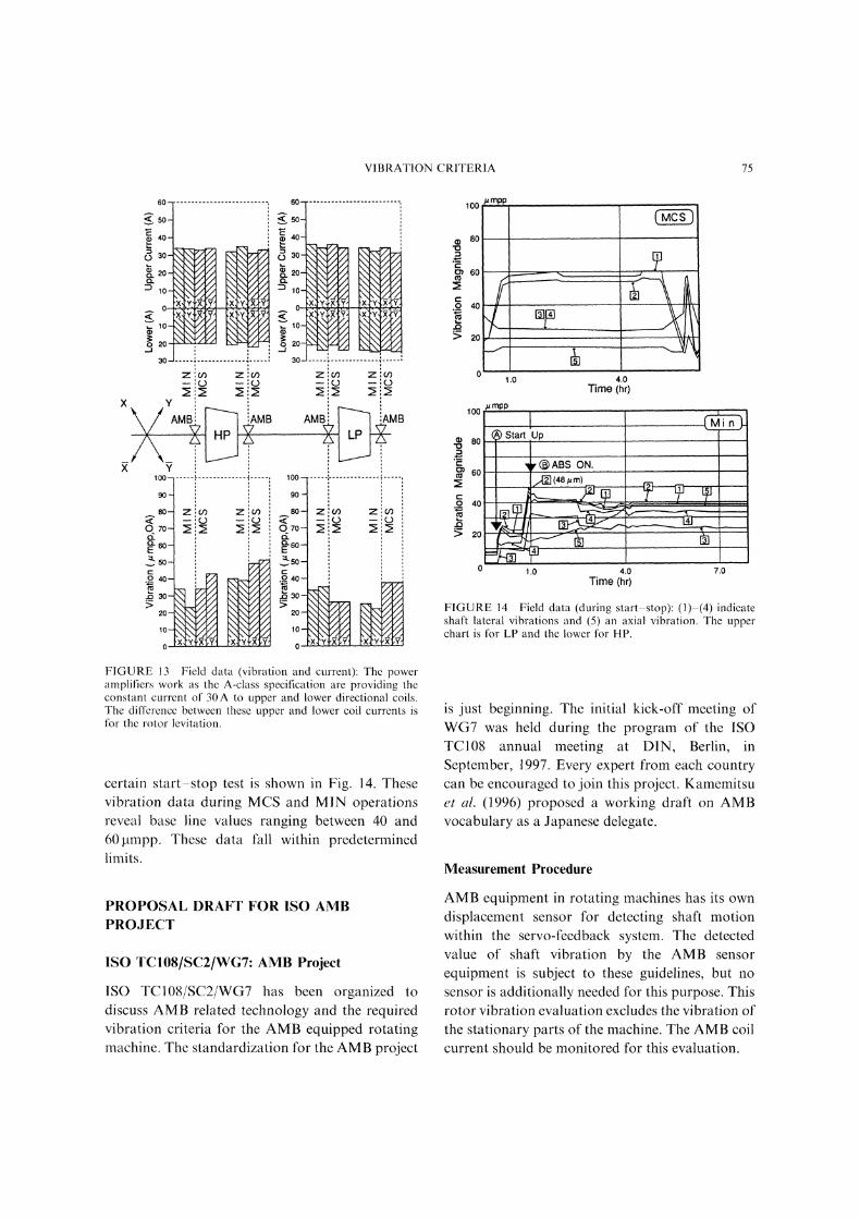
Since the machine was installed on site for thecommission 5 years ago, continuous operationshave been completed including the repeat ofmaintenance every six months without any majorproblem, as of this writing. An example of field datameasured on site is shown in Fig. 13. Steady statedata at normal operations concerning the vibrationand the current are 50 lampp and 3 5% ofthe current
capacity, respectively, as shown in Fig. 13. Bothmeasured values of the vibration and the current are
low enough in comparison with each upper limits;about 100 lampp in vibration amplitude and 60 A incurrent which are indicated on the vertical axes. Anexample of vibration magnitude measured during a
VIBRATION CRITERIA 75
O0
O0/ mpp
80
60 =._o 40._ I]l]> 20
1.0 4.0Time (hr)
100
80
a 6O
0 4O
> 20
mpp
Start, UP
( ABS oN.](48/m)
0 1.0 4.0 7.0Time (hr)
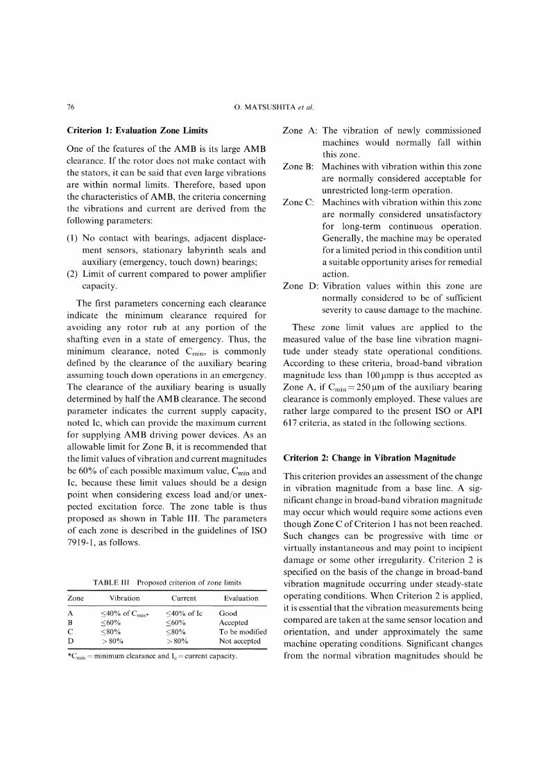
FIGURE 14 Field data (during start-stop): (1)-(4) indicateshaft lateral vibrations and (5) an axial vibration. The upperchart is for LP and the lower for HP.
FIGURE 13 Field data (vibration and current): The poweramplifiers work as the A-class specification are providing theconstant current of 30 A to upper and lower directional coils.The difference between these upper and lower coil currents isfor the rotor levitation.
certain start-stop test is shown in Fig. 14. Thesevibration data during MCS and MIN operationsreveal base line values ranging between 40 and60pmpp. These data fall within predeterminedlimits.
is just beginning. The initial kick-off meeting ofWG7 was held during the program of the ISOTC108 annual meeting at DIN, Berlin, inSeptember, 1997. Every expert from each countrycan be encouraged to join this project. Kamemitsuel al. (1996) proposed a working draft on AMBvocabulary as a Japanese delegate.
Measurement Procedure
PROPOSAL DRAFT FOR ISO AMBPROJ.ECT
ISO TC108/SC2/WG7: AMB Project
ISO TC108/SC2/WG7 has been organized todiscuss AMB related technology and the requiredvibration criteria for the AMB equipped rotatingmachine. The standardization for the AMB project
AMB equipment in rotating machines has its owndisplacement sensor for detecting shaft motionwithin the servo-feedback system. The detectedvalue of shaft vibration by the AMB sensor
equipment is subject to these guidelines, but no
sensor is additionally needed for this purpose. Thisrotor vibration evaluation excludes the vibration ofthe stationary parts of the machine. The AMB coilcurrent should be monitored for this evaluation.
76 O. MATSUSHITA et al.
Criterion 1" Evaluation Zone Limits
One of the features of the AMB is its large AMBclearance. If the rotor does not make contact withthe stators, it can be said that even large vibrationsare within normal limits. Therefore, based uponthe characteristics of AMB, the criteria concerningthe vibrations and current are derived from thefollowing parameters:
(1) No contact With bearings, adjacent displace-ment sensors, stationary labyrinth seals andauxiliary (emergency, touch down) bearings;
(2) Limit of current compared to power amplifiercapacity.
The first parameters concerning each clearanceindicate the minimum clearance required foravoiding any rotor rub at any portion of theshafting even in a state of emergency. Thus, theminimum clearance, noted Cmin, is commonlydefined by the clearance of the auxiliary bearingassuming touch down operations in an emergency.The clearance of the auxiliary bearing is usuallydetermined by half the AMB clearance. The secondparameter indicates the current supply capacity,noted Ic, which can provide the maximum currentfor supplying AMB driving power devices. As anallowable limit for Zone B, it is recommended thatthe limit values ofvibration and current magnitudesbe 60% of each possible maximum value, Cmin andIc, because these limit values should be a designpoint when considering excess load and/or unex-
pected excitation force. The zone table is thusproposed as shown in Table III. The parametersof each zone is described in the guidelines of ISO7919-1, as follows.
TABLE III Proposed criterion of zone limits
Zone Vibration Current Evaluation
A <_40% of Cmin, _<40% of Ic GoodB <_60% <_60% AcceptedC <_80% <_80% To be modifiedD > 80% > 80% Not accepted
*Cmi minimum clearance and Ic current capacity.
Zone A: The vibration of newly commissionedmachines would normally fall withinthis zone.
Zone B: Machines with vibration within this zoneare normally considered acceptable forunrestricted long-term operation.
Zone C: Machines with vibration within this zoneare normally considered unsatisfactoryfor long-term continuous operation.Generally, the machine may be operatedfor a limited period in this condition untila suitable opportunity arises for remedialaction.
Zone D: Vibration values within this zone are
normally considered to be of sufficientseverity to cause damage to the machine.
These zone limit values are applied to themeasured value of the base line vibration magni-tude under steady state operational conditions.According to these criteria, broad-band vibrationmagnitude less than 100 lampp is thus accepted as
Zone A, if Cmin 250 gm of the auxiliary bearingclearance is commonly employed. These values arerather large compared to the present ISO or API617 criteria, as stated in the following sections.
Criterion 2: Change in Vibration Magnitude
This criterion provides an assessment of the changein vibration magnitude from a base line. A sig-nificant change in broad-band vibration magnitudemay occur which would require some actions even
though Zone C of Criterion has not been reached.Such changes can be progressive with time or
virtually instantaneous and may point to incipientdamage or some other irregularity. Criterion 2 isspecified on the basis of the change in broad-bandvibration magnitude occurring under steady-stateoperating conditions. When Criterion 2 is applied,it is essential that the vibration measurements beingcompared are taken at the same sensor location andorientation, and under approximately the samemachine operating conditions. Significant changesfrom the normal vibration magnitudes should be
VIBRATION CRITERIA 77
regulated to be less than 25% of the upperboundary value of Zone B, as defined in TableIII, because a potentially serious fault may beindicated. When change in vibration magnitudeexceeds this value, diagnostic investigations shouldthen be initiated to determine the reason for thechange and to decide what further action is
necessary.
Comparison with Present Criteria
Assuming that the minimum clearance of
Cmin 250 gm is employed in usual AMB turbocompressors, each zone value of our evaluationcriteria mentioned in the previous section isproposed as shown in Table IV. According to ourproposal, even in Zone A, the large value of100 lampp is accepted.
If the present criteria, ISO 7917-3 (CoupledIndustrial Machine), concerning the bearing vibra-tions oflarge scale turbo machines were applied, thefollowing vibration regulations would be:
Zone A" Spp 4800/v/ (e.g., Spp 44 tmpp,
if Trip 11,445 rpm),
Zone B" Spp- 9000/v/- (e.g., Spp- 84 txmpp,
if Trip 11,445 rpm).
According to the API 617-6 standard criteriaregarding centrifugal compressors, the followingvibration regulations would be:
4 /12,000aPl 617-6, Lv- 25. V)V-csand Lv < 25.4 tmpp,
TABLE IV Example of criteria
Criterion 1: Zone limitsZone AZone BZone CZone D
Criterion 2: Vibration change
where NMcs=maximum continuous speed (e.g.,Lv=25.4gmpp, if MCS- ll,445rpm). Thesevalues are too severe for the commission to exert
AMB rotors.As mentioned in these case studies, these
proposed evaluation values seem shockingly largecompared to present related criteria. However,these values fall within safe parameters and is our
recommendation.
Comparison with Experimental Data
As stated in the literature, Fukushima et al. (1994),a Hitachi AMB centrifugal compressor, as shown inFig. 1, was installed in a refinery plant. As shown inFig. 12 which agreed with this vender-customerproject, the alarm level at the maximum continuousspeed was determined as 158 x 0.8 126 gmpp, i.e.,approximately the half of the auxiliary bearingclearance of 230 gm. The corresponding field dataindicate the vibration magnitude of about 60 gmppat maximum which satisfied their own criteria.On the other hand, because this Hitachi AMB
centrifugal compressor employed the auxiliarybearing clearance of Cmi 230 gm, our proposedcriteria for ISO standards are provided in Table Vin which the limit value of Zone A is recommendedby Cmi x 40% =92gmpp. It is found that this
machine has been operating under normal workingconditions while satisfying the vibration evaluationcriterion of Zone A.
CONCLUSIONS
Japanese experts have prepared a draft proposalfor vibration criterion to be applied to industrialturbo machines equipped with AMBs. Prior to
TABLE V Example of criteria
Less than 100 gmpp Criterion 1: Zone limitsLess than 150 gmpp Zone A Less than 92 gmppLess than 200 tmpp Zone B Less than 138 gmppBeyond 200 gmpp Zone C Less than 184 gmppLess than 38 gmpp Zone D Beyond 184 gmpp
In the case of Cmi 250 gin. In the case of Cmi 230 gm.
78 O. MATSUSHITA et al.
determining the zone limit values, the design reviewof AMB equipped compressors was executed with
respect to the relationship between AMB dynamiccharacteristics and critical speed design of flexiblerotors in comparison with the case of oil filmbearing type compressor rotors. The vibrationlimits are proposed through the determination ofthe minimum possible clearance which avoids allcontact and/or rubbing at any location between therotor and stator sides. The case studies concerningthe Hitachi compressors equipped with the AMBare successfully functioning under these criteria.
Since the ISO TC108/SC2/WG7 AMB projectwas initiated, the committee would like to. solicitthe review of this draft for vibration evaluationcriteria. Your opinion is welcome to help in thisendeavor.
References
API-617/6 (1995) Centrifugal compressors for general refineryservice.
Balda, M. (1975) Dynamic properties of turboset rotors, IUTAMSymposium on Dynamics of Rotor, Springer Verlag, pp.27 55.
Fukushima, Y. et al. (1994) Totally oil less centrifugalcompressor in oil refinery service, Proceeding ofAdvancementin Bearing and Seal 7kchnologies, Calgary, Canada, pp. 18.118.36.
Habermann, H. and Brunet, M. (1985)The Active magneticbearing enables optimum control of machine vibrations,ASME Paper 85-GT-221.
ISO 7919 5 (1996) Mechanical vibration of non-reciprocatingmachine (ISO TC108/SC2/WGI).
Kanemitsu, Y. et al. (1996) Japanese proposal for internationalstandardization for active magnetic bearing, Proceedinjof the Fifth International Symposium on Magnetic Bearings,Kanazawa, Japan, pp. 265-270.
S.hiraki, K. and Kanki, H. (1979) A new vibration criteria forhigh speed/large capacity turbo machinery, Proceeding ojEighth Turbomachinery Symposium, pp. 59-70.

EENNEERRGGYY MMAATTEERRIIAALLSSMaterials Science & Engineering for Energy Systems
Economic and environmental factors are creating ever greater pressures for theefficient generation, transmission and use of energy. Materials developments arecrucial to progress in all these areas: to innovation in design; to extending lifetimeand maintenance intervals; and to successful operation in more demandingenvironments. Drawing together the broad community with interests in theseareas, Energy Materials addresses materials needs in future energy generation,transmission, utilisation, conservation and storage. The journal covers thermalgeneration and gas turbines; renewable power (wind, wave, tidal, hydro, solar andgeothermal); fuel cells (low and high temperature); materials issues relevant tobiomass and biotechnology; nuclear power generation (fission and fusion);hydrogen generation and storage in the context of the ‘hydrogen economy’; andthe transmission and storage of the energy produced.
As well as publishing high-quality peer-reviewed research, Energy Materialspromotes discussion of issues common to all sectors, through commissionedreviews and commentaries. The journal includes coverage of energy economicsand policy, and broader social issues, since the political and legislative contextinfluence research and investment decisions.
SSUUBBSSCCRRIIPPTTIIOONN IINNFFOORRMMAATTIIOONNVolume 1 (2006), 4 issues per year Print ISSN: 1748-9237 Online ISSN: 1748-9245Individual rate: £76.00/US$141.00Institutional rate: £235.00/US$435.00Online-only institutional rate: £199.00/US$367.00For special IOM3 member rates please emailssuubbssccrriippttiioonnss@@mmaanneeyy..ccoo..uukk
EEDDIITTOORRSSDDrr FFuujjiioo AAbbeeNIMS, Japan
DDrr JJoohhnn HHaalldd, IPL-MPT,Technical University ofDenmark, Denmark
DDrr RR VViisswwaannaatthhaann, EPRI, USA
FFoorr ffuurrtthheerr iinnffoorrmmaattiioonn pplleeaassee ccoonnttaacctt::Maney Publishing UKTel: +44 (0)113 249 7481 Fax: +44 (0)113 248 6983 Email: [email protected] Publishing North AmericaTel (toll free): 866 297 5154 Fax: 617 354 6875 Email: [email protected]
For further information or to subscribe online please visitwwwwww..mmaanneeyy..ccoo..uukk
CCAALLLL FFOORR PPAAPPEERRSSContributions to the journal should be submitted online athttp://ema.edmgr.com
To view the Notes for Contributors please visit:www.maney.co.uk/journals/notes/ema
Upon publication in 2006, this journal will be available via theIngenta Connect journals service. To view free sample contentonline visit: wwwwww..iinnggeennttaaccoonnnneecctt..ccoomm//ccoonntteenntt//mmaanneeyy
NNEEWW
FFOORR 22000066
Maney Publishing on behalf of the Institute of Materials, Minerals and Mining

International Journal of
AerospaceEngineeringHindawi Publishing Corporationhttp://www.hindawi.com Volume 2010
RoboticsJournal of
Hindawi Publishing Corporationhttp://www.hindawi.com Volume 2014
Hindawi Publishing Corporationhttp://www.hindawi.com Volume 2014
Active and Passive Electronic Components
Control Scienceand Engineering
Journal of
Hindawi Publishing Corporationhttp://www.hindawi.com Volume 2014
International Journal of
RotatingMachinery
Hindawi Publishing Corporationhttp://www.hindawi.com Volume 2014
Hindawi Publishing Corporation http://www.hindawi.com
Journal ofEngineeringVolume 2014
Submit your manuscripts athttp://www.hindawi.com
VLSI Design
Hindawi Publishing Corporationhttp://www.hindawi.com Volume 2014
Hindawi Publishing Corporationhttp://www.hindawi.com Volume 2014
Shock and Vibration
Hindawi Publishing Corporationhttp://www.hindawi.com Volume 2014
Civil EngineeringAdvances in
Acoustics and VibrationAdvances in
Hindawi Publishing Corporationhttp://www.hindawi.com Volume 2014
Hindawi Publishing Corporationhttp://www.hindawi.com Volume 2014
Electrical and Computer Engineering
Journal of
Advances inOptoElectronics
Hindawi Publishing Corporation http://www.hindawi.com
Volume 2014
The Scientific World JournalHindawi Publishing Corporation http://www.hindawi.com Volume 2014
SensorsJournal of
Hindawi Publishing Corporationhttp://www.hindawi.com Volume 2014
Modelling & Simulation in EngineeringHindawi Publishing Corporation http://www.hindawi.com Volume 2014
Hindawi Publishing Corporationhttp://www.hindawi.com Volume 2014
Chemical EngineeringInternational Journal of Antennas and
Propagation
International Journal of
Hindawi Publishing Corporationhttp://www.hindawi.com Volume 2014
Hindawi Publishing Corporationhttp://www.hindawi.com Volume 2014
Navigation and Observation
International Journal of
Hindawi Publishing Corporationhttp://www.hindawi.com Volume 2014
DistributedSensor Networks
International Journal of