Embed Size (px)
Citation preview
From BIM to FEM: the analysis of an historical masonry building
P. Crespi1, A. Franchi1, P. Ronca1, N. Giordano1, M. Scamardo1, G. Gusmeroli2 & G. Schiantarelli2 1ABC Department, Politecnico di Milano, Italy 2Engineer, Sondrio, Italy
Abstract
The construction design process is starting to change with the advent of Building Information Modelling technology. Thanks to the high level of BIM interoperability, it has been possible to transform a BIM model of an historical building, obtained from a laser scanner survey, into an accurate 3D Finite Element Model. The model is able to exploit all the geometrical information collected and organized during the survey phase. The object of the analysis is Castel Masegra, a XI century masonry historical building on the alpine mountains overlooking to Sondrio (Italy). The implementation of the BIM model has been carried out by keeping in mind that the final goal was the construction of a reliable finite element model with a compatible and regular mesh, reproducing the irregularities and complexities that could influence the mechanical behaviour of the structure. Once it has been obtained the 3D finite element model, the historical and diagnostic information have been integrated into the BIM model and a construction stage analysis has been studied and then carried out. The huge amount of information and the large number of finite elements employed introduced some difficulties in data management and results interpretation. However, thanks to the always increasing computational capacity of personal computers, it has been possible to deal with a model composed by more than 700,000 elements, obtaining the results in terms of stresses and displacements of the whole building. Keywords: BIM model, historical building, masonry structure, FEM model, construction stage.
www.witpress.com, ISSN 1743-3509 (on-line) WIT Transactions on The Built Environment, Vol 149, © 2015 WIT Press
Building Information Modelling (BIM) in Design, Construction and Operations 581
doi:10.2495/BIM150471
1 Introduction
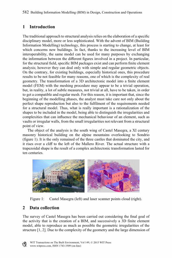
The traditional approach to structural analysis relies on the elaboration of a specific disciplinary model, more or less sophisticated. With the advent of BIM (Building Information Modelling) technology, this process is starting to change, at least for which concerns new buildings. In fact, thanks to the increasing level of BIM interoperability, the same model can be used for many purposes by exchanging the information between the different figures involved in a project. In particular, for the structural field, specific BIM packages exist and can perform finite element analysis; however they can deal only with simple and regular geometric objects. On the contrary, for existing buildings, especially historical ones, this procedure results to be not feasible for many reasons, one of which is the complexity of real geometry. The transformation of a 3D architectonic model into a finite element model (FEM) with the meshing procedure may appear to be a trivial operation, but, in reality, a lot of subtle measures, not trivial at all, have to be taken, in order to get a compatible and regular mesh. For this reason, it is important that, since the beginning of the modelling phases, the analyst must take care not only about the perfect shape reproduction but also to the fulfilment of the requirements needed for a structural model. Thus, what is really important is a rationalization of the shapes to be included in the model, being able to distinguish the irregularities and complexities that can influence the mechanical behaviour of an element, such as vaults or irregular walls, from the small irregularities not relevant from a structural point of view. The object of the analysis is the south wing of Castel Masegra, a XI century masonry historical building on the alpine mountains overlooking to Sondrio (figure 1). It is the only remained of the three castles that dominated the city, and it rises over a cliff to the left of the Mallero River. The actual structure with a trapezoidal shape is the result of a complex architectonic transformation lasted for ten centuries.
Figure 1: Castel Masegra (left) and laser scanner points cloud (right).
2 Data collection
The survey of Castel Masegra has been carried out considering the final goal of the activity that is the creation of a BIM, and successively a 3D finite element model, able to reproduce as much as possible the geometric irregularities of the structure [1, 2]. Due to the complexity of the geometry and the large dimension of
www.witpress.com, ISSN 1743-3509 (on-line) WIT Transactions on The Built Environment, Vol 149, © 2015 WIT Press
582 Building Information Modelling (BIM) in Design, Construction and Operations
the castle it has been decided to perform a laser scanner survey with a robust geodetic network associated, in order to have the best possible mapping in terms of precision, completeness and reliability. The laser scanner survey has been performed using a laser scanner Faro Focus 3D and is made up of 182 scans, 44 millions of points for each scan (roughly 7.7 billion points) registered by means of 269 checkerboards measured also by the Total Station Leica TS30. The point clouds obtained from the laser scanner survey, after the alignment and georeferencing operations, give an incredible 3D definition of the geometry of the analysed object: using appropriate software (e.g. SCENE or Leica Cyclone), it is possible to navigate across it, having a realistic rendering of the building with all its features (figure 1). However, all this amount of information have to be converted in a more efficient and usable way, keeping the desired information, integrating the missing one and discarding all the amount of useless data. The first step of this procedure is the creation of the usual 2D drawings of a building: plans, sections, and façades. In this phase, the great database of pictures made during the survey results to be very useful, allowing the interpretation of eventual lack of information in the clouds. Fortunately, the software AutoCAD, in its last versions, has introduced the possibility of importing and managing the point clouds, with apposite tools for cutting slices or isolating some zones, both natively or using third parts plugin (e.g. Leica Cloudworks), making simpler and simpler the production of plans and sections. Six plans representing the four floors and the roof have been produced, with a covered planar area of about 2700 m2. It has been noticed the great differences with the old plans owned by the Municipality of Sondrio: this underlines the benefits of an accurate laser scanner survey for the reconstruction of such a complex building. Once the plans were drawn, it has been decided to focus the attention on a particular area of the castle: the south wing. This has been done for specific reasons, i.e. the presence, at the first floor, of the dovecote tower, of the “camera picta”, with its very particular umbrella vault, the out of plumb of the dovecote tower and the presence, at the first floor, of a bearing wall resting on the barrel vault.
3 BIM creation
BIM software was initially used only to manage new building constructions [3, 4]. Today it represents an opportunity also for heritage documentation and conservation management, but it still requires a methodological discussion and practical experimentation in order to obtain detailed models of irregular historical buildings, really useful for their preservation and maintenance activities [2, 5]. For the implementation of a rational parametric BIM model it is necessary to distinguish the zones of the building where only simple elements are present from the others with complex or irregular ones; this is necessary because there is a lack of parametric model software for the management of complex and irregular shapes. For this reason, the drafting of 2D drawings before the 3D model construction could be useful.
www.witpress.com, ISSN 1743-3509 (on-line) WIT Transactions on The Built Environment, Vol 149, © 2015 WIT Press
Building Information Modelling (BIM) in Design, Construction and Operations 583
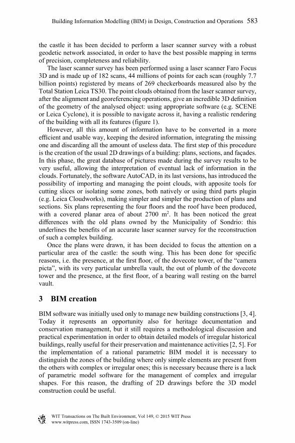
Starting from the section drawings, it has been possible to individuate the out-of plumb and the wall tapering of the external faces of the walls, while the internal ones appears to be reasonably vertical. To overcome the lack of such an element in the BIM software, it has been decided to combine two walls (figure 2): the external façades has been modelled with a “Wall by Face” tool in Revit, while the internal face has been simplified with a normal straight wall for each floor. The two parts of the wall are then joined, with all the irregularities and wall tapering correctly shaped in the BIM model, without losing the possibility to insert the wall stratigraphy.
Figure 2: BIM model: external wall (left), umbrella vault (right).
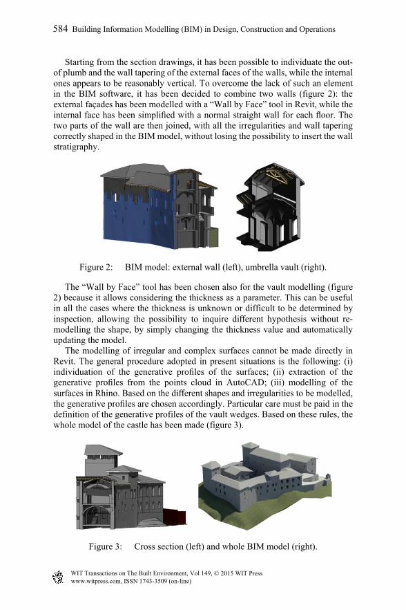
The “Wall by Face” tool has been chosen also for the vault modelling (figure 2) because it allows considering the thickness as a parameter. This can be useful in all the cases where the thickness is unknown or difficult to be determined by inspection, allowing the possibility to inquire different hypothesis without re-modelling the shape, by simply changing the thickness value and automatically updating the model. The modelling of irregular and complex surfaces cannot be made directly in Revit. The general procedure adopted in present situations is the following: (i) individuation of the generative profiles of the surfaces; (ii) extraction of the generative profiles from the points cloud in AutoCAD; (iii) modelling of the surfaces in Rhino. Based on the different shapes and irregularities to be modelled, the generative profiles are chosen accordingly. Particular care must be paid in the definition of the generative profiles of the vault wedges. Based on these rules, the whole model of the castle has been made (figure 3).
Figure 3: Cross section (left) and whole BIM model (right).
www.witpress.com, ISSN 1743-3509 (on-line) WIT Transactions on The Built Environment, Vol 149, © 2015 WIT Press
584 Building Information Modelling (BIM) in Design, Construction and Operations

4 From BIM to 3D finite element model
The aim of this work is the elaboration of a 3D FEM model capable to catch the complex shapes characterizing the load-bearing elements of an historical building (mainly vaults and irregular walls) into a structural analysis. Actually this is not yet possible to be made in a BIM perspective, because BIM software do not deal with 3D solid elements. So, the aim is to find a way to transform the 3D BIM model, already made for architectonic purposes, into a FEM model by exploiting the complex model. The software Midas FEA has been chosen for this work because it allows dealing with 3D elements and it gives the possibility to import advanced 3D geometry to be meshed. A lot of time can be saved in the phase of development of the FEM model, starting from the 3D architectonic BIM model, also taking the advantage of having a much more detailed model with respect to the usual simplified models adopted for these purposes. Previous works [2, 6] have found that, among the different formats that can be imported in Midas FEA, the format STEP is particularly suitable for maintaining the complex shapes during the exchange of information. The FEM model has been generated by using the automatic 3D meshing algorithm provided by Midas FEA. After some preliminary tests involving two different meshing (tetrahedral and hexa-dominant) algorithms, it has been decided to use tetrahedral elements which have been resulted in a better quality mesh. In order to limit the overall number of elements of the model, while maintaining a good quality of the results, a mesh size of 0.2 m has been set. This allows having at least 3–4 elements across the thickness of the load-bearing walls. The meshing process has requested a continuous modification of the BIM model, based on a trial and error procedure, because the most suitable drawings rules in order to achieve a good FEM were not defined a-priori owing to the originality of the work. The major aspects to be corrected were: simplification of the openings drawing, joining of the different parts of the walls and edges offset of the vaults resulting in incompatible meshes. Some of these operations were made by using the classical Boolean operations (union, subtraction and division), but for the great part of the procedure it has been necessary to make the required adjustments working on the single surfaces of the various solids. An overview of the resulting FEM model is depicted in figure 4.
Figure 4: Mesh of the FEM (a), detail of the vaults mesh (b) and roof (c).
www.witpress.com, ISSN 1743-3509 (on-line) WIT Transactions on The Built Environment, Vol 149, © 2015 WIT Press
Building Information Modelling (BIM) in Design, Construction and Operations 585
5 The diagnostic analysis
Masonry buildings, unlike the concrete or steel ones, present a lot of difficulties about the determination of the material properties. This is mainly due to the fact that masonry is a material not homogeneous at all, constituted by various types of materials (stones, bricks), generally kept together by layers of mortar or other bonding agents [7, 8]. Moreover, especially in the case of stone masonry, also the texture is frequently irregular, with alternation of stones having different dimensions. All these issues lead to the fact that the physical and mechanical properties of masonry can have a lot of variability, not only between different buildings, but also among different parts of the same building, or even within the same structural element. For this reason it is very difficult, if not impossible, to resume all these complexities into a single characteristic value, representative of the structural behaviour of the whole bearing structure of a masonry building. In the case of historical buildings, such as Castel Masegra, it is necessary to consider also the degradation of the structural materials used (in particular mortars) and the historical evolution of the building, with all the adjustments and restorations made during the years (e.g. infills, new openings, restoration or substitution of damaged elements with new materials), that can have heavily modified the original masonry and its structural behaviour. In order to better understand the analysed structure, both in terms of composition and structural behaviour, some non-destructive tests (NDT) and minor destructive tests were made. In particular, a thermographic inspection has been performed by the staff of the ABC Department of Politecnico di Milano with the aim to investigate the structure of the castle, to localize not visible degradation phenomena and to check the conditions of temperature and humidity of the superficial masonry layers [9, 10]. Other diagnostic analysis were executed by the engineering society Foppoli Moretta e Associati s.r.l. to characterize the mechanical properties of the masonry structure of the castle. In particular, single and double flat jack tests have been performed respectively to evaluate the actual state of stress in the masonry and its real strength and stiffness. Furthermore, horizontal and vertical cores have been made in order to better understand the masonry texture and the foundation depth and typology. The obtained results show a great heterogeneity both in the masonry characteristics and foundation typology, due to the complex historical evolution of the castle and site topography. Finally, in order to discover the vault thickness, a simple inspection has been made by removing a part of the pavement above some selected vaults.
6 The structural analysis of Castel Masegra
Once the FEM model was ready, it has been decided to make a linear elastic analysis. To do so, the FEM has to be completed by adding the material properties, boundary conditions and applied loads.
www.witpress.com, ISSN 1743-3509 (on-line) WIT Transactions on The Built Environment, Vol 149, © 2015 WIT Press
586 Building Information Modelling (BIM) in Design, Construction and Operations
6.1 Material properties
For the aim of this work, the mechanical properties of the masonry to be considered are the elastic modulus, the Poisson coefficient and the specific weight. The Poisson coefficient has set to the common value of 0.2 while for the specific weight, considering the typology and the dimensions of the stones, a conservative value of 22 kN/m3 has been considered. Regarding the elastic modulus, different hypothesis have been considered in order to have a sensitivity analysis about this parameter. In particular, a first analysis has been carried out considering the characteristic values for a good stone masonry of 3000 N/mm2, given by the Italian design code [11], for the entire masonry structure. In the second case, the results given by the flat jack in-situ tests have been included in the analysis (elastic modulus range 1600–7220 MPa); in particular it has been decided to consider the elastic modulus calculated from the loading-unloading cycles. These material properties have been assigned by subdividing the castle in zones, based both on historical evolution and state of conservation of the materials. The stiffness obtained from each flat jack test has been extended to its surrounding area.
6.2 Loads
The self-weight of the load-bearing elements is automatically computed by the FEM software given the geometry of the model. On the contrary, the dead loads, due to the weight of the elements that have not been modelled, have been applied to the structure as distributed pressure loads. The main elements to be converted into dead loads, not included in the model, are the infilling materials on the vaults and the wooden slabs. Regarding the vault infilling, the main problem was the possibility to reproduce the variability of its thickness along the surface of the vaults. This has been effectively possible by the definition of a linear function of the infilling thickness in order to assign to each vault element face the appropriate infilling weight load. The weight of the wooden slabs has been calculated and appropriately distributed directly on the walls, according to the span direction. In particular, the dead load applied on each wall has been redistributed on the first strip of finite elements along the thickness (i.e. over the first 20 cm of wall), at the appropriate height. All the finishes have been included into the distributed dead load applied on the relative vault or slab. Moreover, also the active lateral soil pressure has been taken into account among the dead loads; its linear variability with depth has been considered. The soil properties have been hypothesized considering the absence of clay and assuming a granular soil as reference.
6.3 Boundary conditions
The setting of boundary conditions is one of the most important issues to be solved. In fact, the castle rises on a cliff: its different parts have different foundation levels
www.witpress.com, ISSN 1743-3509 (on-line) WIT Transactions on The Built Environment, Vol 149, © 2015 WIT Press
Building Information Modelling (BIM) in Design, Construction and Operations 587
and rest on different materials. Some walls are directly founded on the outcropping rock while others have shallow foundations on soil. The information regarding the foundation typologies have been obtained in part from the coring made during the diagnostic analysis, in part directly observing the wall base, and in part referring to the advices given by the Municipality of Sondrio, based on some maintenance works made in the castle. However in some cases, the information was completely missed and some hypotheses have been made considering the conditions of the surrounding area. As a first assumption, fixed restraints have been applied to the lower end of each wall, at the corresponding foundation depth. However, in a case like this, where the different parts of the castle are founded in heterogeneous conditions and at different levels, the structural behaviour can be strongly influenced by the boundary conditions set. For this reason, a second hypothesis has been made by assuming the soil and the rock as a Winkler elastic subgrade. The moduli of subgrade reaction have been assigned to the different walls on the basis of literature values due to the lack of specific in-situ experimental data.
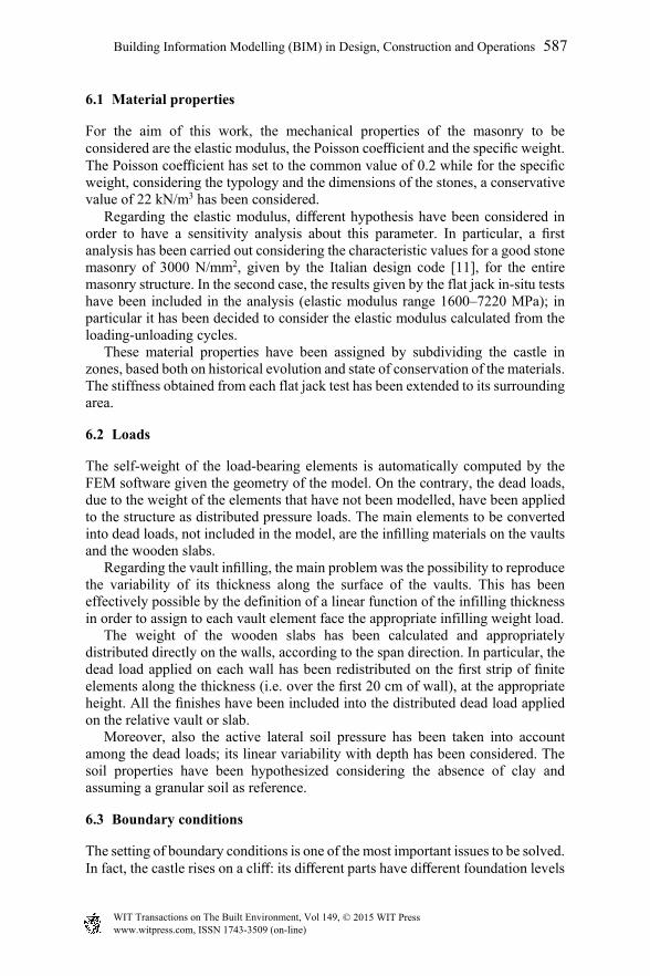
6.4 Construction stages
Since the castle has not been built in a single step, but it is the result of a lot of complex historical transformation, it has been decided to reproduce the historical evolution also in the structural analysis, by making a construction stage analysis. The different parts of the castle are gradually added to the model; for each stage the analysis under self-weight is performed, and the parts of the castle belonging to the successive stage are added on the deformed configuration of the previous stage. This way of proceeding has been undertaken for tree different reasons:
to reproduce the historical evolution of the architectonic complex, that can influence the load redistribution;
to try to reduce the resulting stress concentrations at the different foundation levels, because of the model hypothesis of fixed restraints that doesn’t allow any settlement;
to avoid strange load redistribution with stress concentration between parts with different material properties: in fact, in case of very different elastic modulus among different parts, such as in this case, the weaker part tends to hang to the stronger one, following in unrealistic stress patterns.
Obviously this approach presents the drawback that the computational cost increases proportionally with the number of stages: if a one-step analysis takes about 5 minutes to be completed, a 7 stages analysis takes almost 40 minutes.
6.5 Model calibration: comparison with single flat jack results
In order to test the model reliability, and to calibrate the hypotheses made, the vertical stresses obtained in correspondence of the location of the single flat jack tests have been compared with the test results themselves.
www.witpress.com, ISSN 1743-3509 (on-line) WIT Transactions on The Built Environment, Vol 149, © 2015 WIT Press
588 Building Information Modelling (BIM) in Design, Construction and Operations
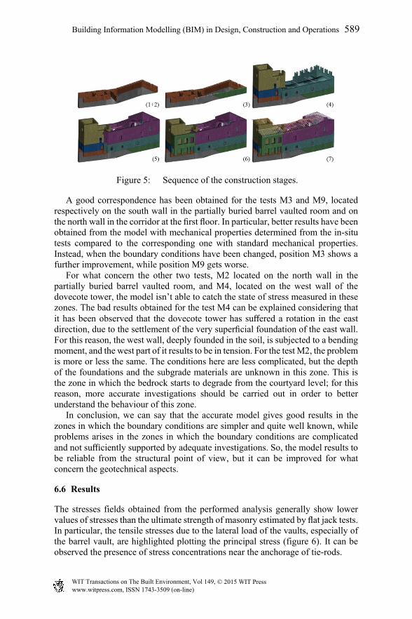
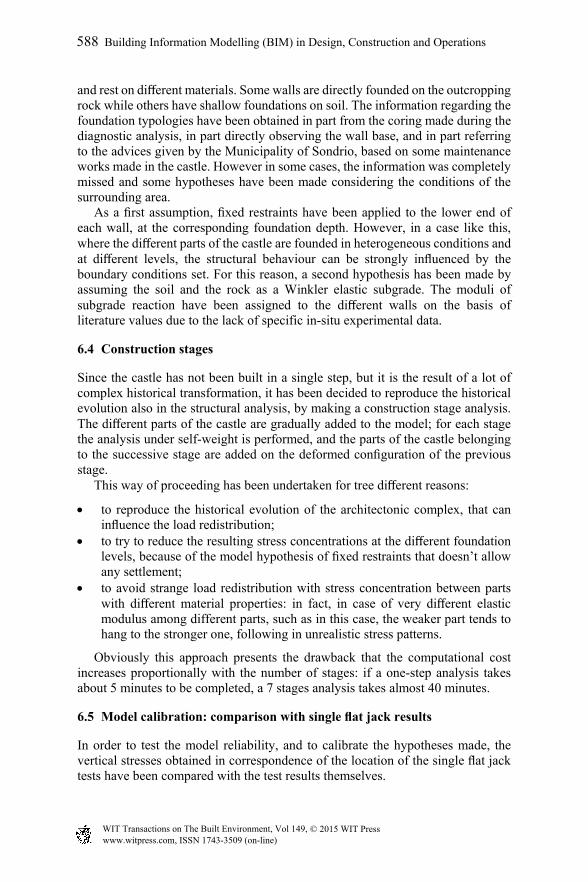
Figure 5: Sequence of the construction stages.
A good correspondence has been obtained for the tests M3 and M9, located respectively on the south wall in the partially buried barrel vaulted room and on the north wall in the corridor at the first floor. In particular, better results have been obtained from the model with mechanical properties determined from the in-situ tests compared to the corresponding one with standard mechanical properties. Instead, when the boundary conditions have been changed, position M3 shows a further improvement, while position M9 gets worse. For what concern the other two tests, M2 located on the north wall in the partially buried barrel vaulted room, and M4, located on the west wall of the dovecote tower, the model isn’t able to catch the state of stress measured in these zones. The bad results obtained for the test M4 can be explained considering that it has been observed that the dovecote tower has suffered a rotation in the east direction, due to the settlement of the very superficial foundation of the east wall. For this reason, the west wall, deeply founded in the soil, is subjected to a bending moment, and the west part of it results to be in tension. For the test M2, the problem is more or less the same. The conditions here are less complicated, but the depth of the foundations and the subgrade materials are unknown in this zone. This is the zone in which the bedrock starts to degrade from the courtyard level; for this reason, more accurate investigations should be carried out in order to better understand the behaviour of this zone. In conclusion, we can say that the accurate model gives good results in the zones in which the boundary conditions are simpler and quite well known, while problems arises in the zones in which the boundary conditions are complicated and not sufficiently supported by adequate investigations. So, the model results to be reliable from the structural point of view, but it can be improved for what concern the geotechnical aspects.
6.6 Results
The stresses fields obtained from the performed analysis generally show lower values of stresses than the ultimate strength of masonry estimated by flat jack tests. In particular, the tensile stresses due to the lateral load of the vaults, especially of the barrel vault, are highlighted plotting the principal stress (figure 6). It can be observed the presence of stress concentrations near the anchorage of tie-rods.
www.witpress.com, ISSN 1743-3509 (on-line) WIT Transactions on The Built Environment, Vol 149, © 2015 WIT Press
Building Information Modelling (BIM) in Design, Construction and Operations 589

Figure 6: Principal stress: north side (left), south side (right).
Another interesting result is the different deforming behaviour of the different material parts. Thus, the advisability to make a construction stages analysis is evident in order to follow the construction sequence avoiding unreal hanging phenomena of the weakest parts on the strongest ones. A further confirmation of the reliability of the model follows from the comparison of the tensile stressed regions and the crack pattern detected on site. A first example is the presence of an unloading arch on the east wall of the dovecote tower. The first principal stress matches with the crack pattern individuated on site. This behaviour can be explained considering that on the other side of the wall there is the umbrella vault. The unloading arch is due to the presence of two openings, now partially infilled, which weaken the wall itself, exactly below the vault corbels (figure 7). A stress concentration at the top of the two openings can be noticed where two repaired cracks can be seen.
(a) (b)
Figure 7: Tensile stresses in the dovecote tower wall (a) and cracks (b).
Another interesting example is located in the partially underground southwest room, at the top of one of the lunettes of the north side of the barrel vault (figure 8(a)), where the results matches the cracking position and its direction of propagation. In the same room, a similar example can be found around the opening in the west wall (figure 8(b)).
7 Conclusions
A detailed BIM model of Masegra Castle has been implemented starting from the points cloud obtained with a laser scanner survey. The BIM model of the castle was then transformed into an accurate 3D finite element model taking into account
www.witpress.com, ISSN 1743-3509 (on-line) WIT Transactions on The Built Environment, Vol 149, © 2015 WIT Press
590 Building Information Modelling (BIM) in Design, Construction and Operations
(a) (b)
Figure 8: Tensile stresses – underground room: north (a) and west (b) walls.
all the geometric information together with the historical and diagnostic analysis. This procedure has implied a significant effort for its great interdisciplinarity, required to deal with all the aspects of the problem when trying to consider different fields by using the same model for many purposes. This necessity has become evident especially in the modelling phase, where a lot of specific procedures have been checked in order to find the best way to convert the BIM model into a finite element model. The selected conversion procedure between BIM and FEM models can be very useful to study the structural behaviour of historical buildings, especially when very pronounced irregularities are present. In particular, such an accurate geometric model can be a precious tool to better understand the behaviour of particular elements such as vaults or irregular walls. A possible drawback of employing a fully three-dimensional model for a structural analysis is that a great number of finite elements is required for the discretization of the problem. In this case, a total of 720,393 continuum finite elements were considered in the mesh of the castle. The construction stage analysis performed with the FEM model has allowed to check the stress level in the castle structures, which is a preliminary information for the detailing of the restoration works to be planned.
Acknowledgements
The authors would like to thanks Eng. Francesco Barri and all the Municipality of Sondrio for the on-site support. Furthermore, many thanks are also due to prof. Raffaella Brumana and the survey team of ABC Department of Politecnico di Milano.
References
[1] Brumana, R., Oreni, D., Cuca, B., Binda, L., Condoleo, P. & Triggiani, M., Strategy for integrated surveying techniques finalized to interpretative models in a byzantine church, Mesopotam, Albania. International Journal of Architectural Heritage, 8, pp. 886-924, 2014.
www.witpress.com, ISSN 1743-3509 (on-line) WIT Transactions on The Built Environment, Vol 149, © 2015 WIT Press
Building Information Modelling (BIM) in Design, Construction and Operations 591
[2] Oreni, D., Brumana, R., Della Torre, S., Banfi, F., Barazzetti, L. & Previtali, M., Survey turned into HBIM: the restoration and the work involved concerning the Basilica di Collemaggio after the earthquake (L’Aquila). ISPRS Annals of the Photogrammetry, Remote Sensing and Spatial Information Sciences, vol. II, pp. 267-273, 2014.
[3] Eastman, C., Teicholz, P., Sacks, R. & Liston, K., BIM Handbook – A guide to Building Information Modeling for owners, managers, designers and contractors, John Wiley & Sons, Inc., 2008.
[4] Lee, G., Sacks, R. & Eastman, C. M., Specifying Parametric Building Object Behavior (BOB) for a Building Information Modeling System. Automation in Construction, 15(6), pp. 758-776, 2006.
[5] Oreni, D., Brumana, R., Cuca, B. & Georgopoulos, A., HBIM for conservation and management of built heritage: Towards a library of vaults and wooden bean floors. ISPRS Annals of Photogrammetry, Remote Sensing and Spatial Information Sciences, (II-5/W1), pp. 215-221, 2013.
[6] Arrighetti, S., Bertola, L. & Livetti, A., Restituire Collemaggio. Master’s thesis, Politecnico di Milano, 2014.
[7] Binda, L. & Tiraboschi, C., Flat-Jack Test: a slightly destructive technique for the diagnosis of brick and stone masonry structures. International journal for restoration of buildings and monuments, 5, pp. 449-472, 1999.
[8] Maierhofer, C., Combination of Non-Destructive testing methods for the assessment of masonry structures. Proceedings of the 1st International SACoMaTiS Symposium, 2, pp. 715-726, 2008.
[9] Rosina, E. & Grinzato, E., Infrared and Thermal Testing for Conservation of Historic Building. Material Evaluation, 59(8), pp. 942-954, 2001.
[10] Rosina, E., Ludwig, N. & Redaelli, V., Metodi per la misura dell’umidità nei materiali dell’edilizia storica: legno e intonaci. X Congresso Nazionale AIPnD, pp. 165-173, 2003.
[11] Norme Tecniche per le Costruzioni, Italian Ministerial Decree, 2008.
www.witpress.com, ISSN 1743-3509 (on-line) WIT Transactions on The Built Environment, Vol 149, © 2015 WIT Press
592 Building Information Modelling (BIM) in Design, Construction and Operations