Embed Size (px)
Citation preview

FROG SERIES
IN-GROUND OPERATOR FOR SWING GATES
INSTALLATION MANUAL
FROG J

2
EN
GLIS
H
The
data
and
info
rmat
ion
show
n in
this
dia
logu
e m
ay b
e ch
ange
d by
Cam
e Ca
ncel
li Au
tom
atic
i S.p
.A. a
t any
tim
e w
ithou
t prio
r war
ning
.
4.1 Gate Operator
4 Description
2.1 Intended use
1 Legend of symbols This symbol tells you to read the section with particular care.
This symbol tells you that the sections concern safety issues.
This symbol tells you what to say to the end-users.
2 Intended use and application
The FROG-J operator is designed to automate swing gates used in residential or condominium settings. The use of this product for purposes other than those described above and installation executed in a manner other than as instructed in this technical manual are prohibited.
3 Reference Standards
“IMPORTANT INSTALLATION, SAFETY INSTRUCTIONS”
“CAUTION: IMPROPER INSTALLATION MAY CAUSE SERIOUS DAMAGE, FOLLOW ALL INSTALLATION INSTRUCTIONS CAREFULLY”
“THIS MANUAL IS ONLY FOR PROFESSIONAL OR QUALIFIED INSTALLERS”
2.2 Application
This product is engineered and manufactured by CAME cancelli automatici s.p.a. and complies with current safety regulations.Guaranteed 24 months if not tampered with.The main component parts of the operator are a foundation casing, a release group, a gearmotor and a transmission arm.The foundation casing is made of 1.5 mm thick ABS plastic on the sides and of 4mm galvanised steel on the bottom plate. Inside is housed the release group with custom key for manually releasing the operator. The gearmotor, is made of cast aluminium in which works an irreversible, gear-ratio and, endless screw and helical crown system.
4.2 Technical features
FROG J Control board power supply: 230 A.C. 50/60HzMotor power supply: 24V D.C. 50/60HzMax draw: 10 A Nominal voltage: 240WMax Torque.: 260NOpening time (90°): 15 sGear ratio: 1/1396,5Duty cycle: Intensive useProtection Rating: IP67Weight: .. kgInsulation rating:
For intensive use and condominiums: max weight of the gate 200kg, and max length 1.8m.
The company: CAME Cancelli Automatici s.p.a. is ISO 9001:2000 quality certified; is has also obtained the ISO 14001 environ-mental safeguarding certification. Came engineers and manufactures all of its products in Italy.This product complies with the following standards: EN 12978, UNI EN 954-1, CEI EN 60335-1, UNI EN 12453.

3
ENGLISH
The
data
and
info
rmat
ion
show
n in
this
dia
logu
e m
ay b
e ch
ange
d by
Cam
e Ca
ncel
li Au
tom
atic
i S.p
.A. a
t any
tim
e w
ithou
t prio
r war
ning
.
4.4 Dimensions
4.3 Description of parts
FROG J OPERATO
1) Gate pin-housing ring2) Gearmotor pin-housing ring3) Gearmotor mobile ring4) Endstop adjustment set screw 5) Release group6) Cover7) Operator8) In-ground case9) Custom key for release group
(mm)
1
7
6
5
8
2
4
4
9
3

4
EN
GLIS
H
The
data
and
info
rmat
ion
show
n in
this
dia
logu
e m
ay b
e ch
ange
d by
Cam
e Ca
ncel
li Au
tom
atic
i S.p
.A. a
t any
tim
e w
ithou
t prio
r war
ning
.
Make sure you have all the tools and materials you will need for the installation at hand to work in total safety and com-pliance with the current standards and regulations. The following figure illustrates the minimum equipment needed by the installer.
5.2 Tools and materials
5 Installation
Before installing, do the following:• Make sure you have a suitable omnipolar cut-off device with contacts more than 3 mm apart, and independent (sectioned off) power supply.• Make sure you have suitable tubing and conduits for the electrical cables to pass through and be protected against mechanical damage.• Fit tubing to drain away any water leaks which may cause oxidation.• Make sure that any connections inside the case (that provide continuance to the protective circuit) be fitted with extra insulation as compared to the other conductive parts inside;• Make sure the structure of the gate is sturdy, the hinges work and that the is no friction between moving and non-moving parts.• Make sure there is a mechanical stop for opening and closing.
Installation must be carried out by expert qualified personnel and in full compliance with current regulations.
5.1 Preliminary checks
5
ENGLISH
The
data
and
info
rmat
ion
show
n in
this
dia
logu
e m
ay b
e ch
ange
d by
Cam
e Ca
ncel
li Au
tom
atic
i S.p
.A. a
t any
tim
e w
ithou
t prio
r war
ning
.
N.B.: If the cable length differs from that specified in the table, then you must determine the proper cable diameter in the basis of the actual power draw by the connected devices and depending on the standards specified in CEI EN 60204-1.For connections that require several, sequential loads, the sizes given on the table must be re-evaluated based on actual power draw and distances.When connecting products that are not specified in this manual, please follow the documentation provided with said products.
5.3 Cable list and minimum thickness
Connections Type of cable Length of cable 1 < 10 m L. of cable 10 < 20 m L. of cable 20 < 30 m
Control panel power supply 230 3F
FROR CEI 20-22 CEI EN
50267-2-1
3G x 1,5 mm2 3G x 2,5 mm2 3G x 4 mm2
Motor power supply 24V 3 x 1 mm2 3 x 1,5 mm2 3 x 2,5 mm2
flashing lamp 2 x 0,5 mm2 2 x 1 mm2 2 x 1,5 mm2
Photocell transmitters 2 x 0,5 mm2 2 x 0.5 mm2 2 x 0,5 mm2
Photocell receivers 4 x 0,5 mm2 4 x 0,5 mm2 4 x 0,5 mm2
Accessories power supply 2 x 0,5 mm2 2 x 0,5 mm2 2 x 1 mm2
Control and safety devices 2 x 0,5 mm2 2 x 0,5 mm2 2 x 0,5 mm2
Antenna connection RG58 max. 10 m
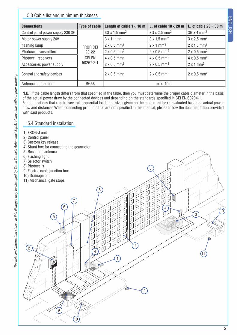
1) FROG-J unit2) Control panel3) Custom key release4) Shunt box for connecting the gearmotor5) Reception antenna6) Flashing light7) Selector switch8) Photocells9) Electric cable junction box10) Drainage pit11) Mechanical gate stops
5
2
8
8
7
9
10
6
1
4
4
11
11
310
11
5.4 Standard installation

6
EN
GLIS
H
The
data
and
info
rmat
ion
show
n in
this
dia
logu
e m
ay b
e ch
ange
d by
Cam
e Ca
ncel
li Au
tom
atic
i S.p
.A. a
t any
tim
e w
ithou
t prio
r war
ning
.
The following illustrations are only examples, given that the space available for anchoring the operator and accessories may vary from gate to gate. It is up to the installer, thus, to choose the most suitable solution.
N.B: illustration view: left side, inside view.
- To facilitate insertion of the in-ground casing, remove the gate and lower hinges. Dig a pit to house the foundation casing, set up the shunt boxes and corrugated plastic conduits for connections coming from the junction box and the drainage tube.N.B.: the number of tubes depends on the type of installation and accessories it will support.
5.5 Preparing for the foundation casing
- Level the foundation casing with the ground and position the its stuffi ng box so that it is perfectly aligned with the gate’s top hinge.Leave to set for at least 24 hours.
- Fill the pit with cement and sink the foundation casing, while making sure that the corrugated plastic tubes and drainage tubes pass through
their apposite holes.

7
ENGLISH
The
data
and
info
rmat
ion
show
n in
this
dia
logu
e m
ay b
e ch
ange
d by
Cam
e Ca
ncel
li Au
tom
atic
i S.p
.A. a
t any
tim
e w
ithou
t prio
r war
ning
.
- Insert the releases into the in-ground box and anchor them using the supplied screws.
- Assemble the transmission arm with the pin-housing ring to the stuffi ng box, anchor them using the (M6x16) set screws and nuts.Warning: the threaded holes for inserting the (m10x90) adjustment set screw of the gate pin-housing ring is to be positioned opposite the threaded hole of the gearmotor pin-housing ring.posizionato dalla parte opposta al foro fi lettato del braccio mobile del motoriduttore.
5.6 Installing the unit
N.B.: view of illustrations: outer side (to simplify the description of the moun-ting phases)
Note: for the right side gearmotor, assemble the gate pin with the pin-housing ring so that is symmetrical to the left side one, see illustration.
Illustration for mounting the left gearmotor
Illustration for mounting the right gearmotor
Threaded hole
Gate pin-housing ring
Transmission arm
Set screw M6x16
Nut M6

8
EN
GLIS
H
The
data
and
info
rmat
ion
show
n in
this
dia
logu
e m
ay b
e ch
ange
d by
Cam
e Ca
ncel
li Au
tom
atic
i S.p
.A. a
t any
tim
e w
ithou
t prio
r war
ning
.
- Attach the gearmotor to the gate pin-housing ring. Turn the adjustment set screw and the nut at the opposite end – without tightening it completely.
- Insert the gearmotor into the in-ground box and anchor it using bolts and washers. N.B.: Place the gearmotor’s pin-housing ring exactly below that of the gate pin and facing the same direction.
- Mount the gate leaf by only inserting the top hinge. Check that the gate leaf opens and closes easily. Bolt into place using the proper bolts or carefully weld the gate leaf to the
transmission arm.
UNI 5739M10x25
Gearmotor pin-housing ring
Set screw M10x90 Nut M10
Gate pin-housing ring
WasherØ10x20

9
ENGLISH
The
data
and
info
rmat
ion
show
n in
this
dia
logu
e m
ay b
e ch
ange
d by
Cam
e Ca
ncel
li Au
tom
atic
i S.p
.A. a
t any
tim
e w
ithou
t prio
r war
ning
.- Set the lever of the release group to the gearmotor.
5.7 Adjusting the mechanical endstops
Closing set screw for left gearmotor
Procedure for adjusting the opening: follow the same steps used in adjusting the closing.
- Before tightening the set screws to adjust the opening and closing of the gate, release the gearmotors (see paragraph for manual releasing).Procedure for adjusting the closing: turn the M10x90 (1) set screw clockwise or counter clockwise; lock the nut so that it is opposite the thread (2).
SX DX
SX DX
Closing set screw for right gearmotor
Opening set screw for right gearmotor
Opening set screw for left gearmotor

10
EN
GLIS
H
The
data
and
info
rmat
ion
show
n in
this
dia
logu
e m
ay b
e ch
ange
d by
Cam
e Ca
ncel
li Au
tom
atic
i S.p
.A. a
t any
tim
e w
ithou
t prio
r war
ning
.
- After making the necessary adjustments and electrical connections (see following chapter), place the cover onto the box and screw it down using the supplied cylinder-head screws.
5.7 Manual release of the gearmotor
- Lift the cover to the release group, insert and turn the key.Turn the release handle clockwise.
- Close the door before manually moving the gate.
Ø4,8x19

11
ENGLISH
The
data
and
info
rmat
ion
show
n in
this
dia
logu
e m
ay b
e ch
ange
d by
Cam
e Ca
ncel
li Au
tom
atic
i S.p
.A. a
t any
tim
e w
ithou
t prio
r war
ning
.6 Connecting to the control panel
When making electrical connections, use the pit the shunt boxes. For further instructions concerning functions and adjustments, consult the control panels technical documentation.
Connecting the 24V d.c. delayed opening gearmotor
1
1) Control panel2) Left gearmotor3) Right gearmotor4) Shunt box5) Junction pit
ZL90 Control panel
Connecting the 24V d.c. delayed closing gearmotor
5
2
3
4
4
230V a.c. power supply
BLUEBROWNBLACK
BLUEBLACKBROWN

12
EN
GLIS
H
The
data
and
info
rmat
ion
show
n in
this
dia
logu
e m
ay b
e ch
ange
d by
Cam
e Ca
ncel
li Au
tom
atic
i S.p
.A. a
t any
tim
e w
ithou
t prio
r war
ning
.
7 Safety instructions
This product must only be employed for its originally intended use. Any other use is wrong and potentially dangerous. The manufacturer cannot be held liable for any damages resulting from wrongful, erroneous or negligent uses.Avoid working close to the hinges or other moving mechanical parts. Stay out of the opening/closing arc when operator is in motion. Do not exercise force against the motion of the operator as this could result in potentially dangerous situations.
Do not allow children to play or loiter within the opening/closing arc of the operator.Keep remote controls and any other command device out the reach of children, to prevent operator from being activated by accident.In the event of anomalous behaviour, stop using the operator immediately.
Danger of crushing hands
Danger of crushing feet
Danger! High voltage
No transit during operation
Important safety instructions

13
ENGLISH
The
data
and
info
rmat
ion
show
n in
this
dia
logu
e m
ay b
e ch
ange
d by
Cam
e Ca
ncel
li Au
tom
atic
i S.p
.A. a
t any
tim
e w
ithou
t prio
r war
ning
.8 Maintenance
8.1 Periodic maintenance
Periodic maintenance to be carried out by the end-user is as follows: wipe clean the glass surface of the photocel-ls; check that the safety devices work properly; remove any obstructions.We suggest checking the state of lubrication and tightness of the anchoring screws on the operator.To check the efficiency of the safety devices, move an object in front of the photocells when gate is closing. If the operator inverts the motion or stops, the photocells are working properly.This is the only maintenance procedure to be carried out with the power source connected.Before performing any maintenance procedures, cut off the main power, to prevent possible accidents due to gate move-ment.To clean the photocells use a water dampened cloth. Do not use solvents or other chemical products which may ruin the devices.In the event of any strange vibrations or squeaking, lubricate the joints with grease, as shown in the diagram.
Make sure there are no plants within the photocell’s beam, and that the gate motion is free of any obstacles.
MALFUNCTIONS POSSIBLE CAUSES CHECK AND REMEDIES
The gate will not open nor close
• There is no power• The gearmotor is released• The remote control’s batteries are run down• The transmitter is broken• The stop button is either stuck or broken• The opening/closing button or the key selector are stuck
• Check that the power is up• Call assistance• Replace batteries• Call assistance• Call assistance• Call assistance
The gate opens but will not close
• The photocells are engaged • Check that photocells are clean and in good working order• Call assistance
The flasher does not work
• The bulb is burnt • Call assistance
8.2 Trouble shooting

14
EN
GLIS
H
The
data
and
info
rmat
ion
show
n in
this
dia
logu
e m
ay b
e ch
ange
d by
Cam
e Ca
ncel
li Au
tom
atic
i S.p
.A. a
t any
tim
e w
ithou
t prio
r war
ning
.
8.3 Extra-ordinary maintenance
Installer’s stamp Operator name
Date of job
Technician’s segnature
Requester’s segnature
Job performed_____________________________________________________________________________________________________________________________________________________________________________________
The following table serves to note down any extraordinary maintenance, repairs or improvements performed by spe-cialised firms.N.B.: Any extraordinary maintenance must be performed by specialised technicians.
Installer’s stamp Operator name
Date of job
Technician’s segnature
Requester’s segnature
Job performed_____________________________________________________________________________________________________________________________________________________________________________________
Installer’s stamp Operator name
Date of job
Technician’s segnature
Requester’s segnature
Job performed_____________________________________________________________________________________________________________________________________________________________________________________
Extra-ordinary maintenance log
Date Notes Segnature
Periodic maintenance log (for end-user) (every 6 moths)

15
ENGLISH
The
data
and
info
rmat
ion
show
n in
this
dia
logu
e m
ay b
e ch
ange
d by
Cam
e Ca
ncel
li Au
tom
atic
i S.p
.A. a
t any
tim
e w
ithou
t prio
r war
ning
.
In its premises, CAME cancelli automatici s.p.a. implements an Environmental Management System certified in com-pliance with the UNI EN ISO 14001 standard to ensure environmental protection.Please continue our efforts to protect the environment—which CAME considers one of the cardinal elements in the develop-mentof its operational and market strategies—simply by observing brief recommendations as regards disposal: DISPOSAL OF PACKAGINGThe packaging components (cardboard, plastic, etc.) are all classifiable as solid urban waste products and may be disposed of easily, keeping in mind recycling possibilities.
Prior to disposal, it is always advisable to check specific regulations in force in the place of installation.
PLEASE DISPOSE OF PROPERLY!
PRODUCT DISPOSALOur products are made up of various types of materials. Most of them (aluminium, plastics, iron, electrical wires, etc.) may be disposed of in normal garbage collection bins and can be recycled by disposing of in specific recyclable material collection bins and disposal in authorized centres. Other components (electrical boards, remote control batteries, etc.), however, may contain polluting substances. They should therefore be removed and given to qualified service companies for proper disposal.Prior to disposal, it is always advisable to check specific regulations in force in the place of disposal.PLEASE DISPOSE OF PROPERLY!
9 Demolition and disposal
MANUFACTURER’S DECLARATION OF CONFORMITYPursuant to annex II B of the Machinery Directive 98/37/EC
CAME Cancelli Automatici S.p.A. via Martiri della Libertà, 15 31030 Dosson di Casier - Treviso - ITALY tel (+39) 0422 4940 - fax (+39) 0422 4941 internet: www.came.it - e-mail: [email protected]
Declares under its own responsibility that the equipments for automatic garage doors and gates listed below:
… comply with the National Law related to the following European Directives and to the applicable parts of the following Standards.
98/37/CE - 98/79/CE MACHINERY DIRECTIVE 98/336/CEE - 92/31/CEE ELECTROMAGNETIC COMPATIBILITY DIRECTIVE
73/23/CEE - 93/68/CE LOW VOLTAGE DIRECTIVE
89/106/CEE CONSTRUCTION PRODUCTS DIRECTIVE
EN 13241-1 EN 12635 EN 61000-6-2 EN 12453 EN 12978 EN 61000-6-3 EN 12445 EN 60335-1 EN 60204-1
IMPORTANT WARNING!Do not use the equipment specifi ed here above, before completing the full installation
In full compliance with the Machinery Directive 98/37/EC
MANAGING DIRECTORMr. Andrea Menuzzo
IN-GROUND OPERATOR FOR SWING GATESFROG-J
10 Maker’s statement
Reference code to request a true copy of the original: DDF B EN .............. ver.1.0
Installer’s stamp Operator name
Date of job
Technician’s segnature
Requester’s segnature
Job performed_____________________________________________________________________________________________________________________________________________________________________________________
Installer’s stamp Operator name
Date of job
Technician’s segnature
Requester’s segnature
Job performed_____________________________________________________________________________________________________________________________________________________________________________________

Cod.
119
AU14
ver
. 0.1
10/
06 ©
CAM
E CA
NCEL
LI A
UTOM
ATIC
I
CAME UNITED KINGDOM LTDUNIT 3, ORCHARD BUSINESS PARK TOWN
STREET, SANDIACRE NOTTINGHAM - NG10 5BP - U.K.
Tel 0044 115 9210430
Fax 0044 115 9210431