Embed Size (px)
Citation preview

Friction Stir Channeling Industrial Applications
Prototype Design and Production
Miguel Filgueiras Soares Ferraz
Dissertation for the Degree of Master in
Mechanical Engineering
Jury
Chairperson: Professor Doutor Rui Manuel dos Santos Oliveira Baptista
Supervisor: Professor Doutor Pedro Miguel dos Santos Vilaça da Silva
Members: Professora Doutora Rosa Maria Mendes Miranda
Professora Doutora Virgínia Isabel Monteiro Nabais Infante
May 2012

i
Agradecimentos
Venho por este meio expressar a minha profunda gratidão ao meu orientador, Professor
Pedro Miguel dos Santos Vilaça, por me ter convidado para integrar um projecto tão desafiante e
pioneiro no seio do seu talentoso grupo de trabalho, o iStir. Como também pelo seu apoio pessoal,
tempo investido, material, equipamento e input técnico crucial. Agradeço com a maior das
sinceridades todo o seu empenho e interesse.
Um sincero obrigado à Professora Luisa Coutinho pelo seu apoio a nível de escrita e compilar
um relatório bem estruturado e detalhado de todo o trabalho desenvolvido pelo autor.
O especial agradecimento ao Mestre João Gandra por toda o seu conhecimento, dedicação e
valor acrescido que deu para o desenvovlvimento deste trabalho como também ao grupo iStir, mas
especialmente por todo o seu apoio e amizade.
O meu profundo obrigado ao Mestre Filipe Nascimento por toda a sua ajuda prestada durante
o trabalho experimental decorrido na Secção de Tecnologia Mecânica, Instituto Superior Técnico,
como também do seu know-how na tecnologia deste trabalho mas acima de tudo o seu apoio
incondicional em qualquer altura.
Um sincero obrigado ao Mestre José Pedro por toda a sua motivação inspiradora e
disponibilidade em arranjar soluções para os mais variados problemas.
Agradeço à Mestre Catarina Vidal pela ajuda prestada durante todo o desenvolvimento deste
trabalho como também na fase de concepção de ferramentas para o mesmo.
Expresso também o meu apreço pelo Sr. João Luís por um excelente trabalho de produção
das ferramentas e de outros componentes projectados.
Aos meus colegas e futuros Mestres Tiago Carneiro, Miguel Passanha, Manuel Hall, Luís
Lobo da Costa, André Coutinho, João Avelar, Martim Teixeira, João Jeremias e Rui Pedro Silva entre
muitos outros, expresso a minha profunda consideração pela forte amizade que se desenvolveu ao
longo destes 5 anos e todo o apoio sistemático durante a realização deste trabalho.

ii
Acknowledgments
I would like to express deep gratification to my supervisor, Professor Pedro Miguel dos Santos
Vilaça da Silva, for inviting me to join such a challenging project, giving me the opportunity to work in
the development of a state of art technology with such a talented group of people as his iStir work
group. As well as for providing material, equipment, crucial technical support and time invested.
Honest thanks for all the commitment and personal interest.
The author would also like to express his gratitude to Professora Luisa Coutinho for the final
aid in compiling a well structured and detailed report on the work developed by the author.
A special thank to MSc. João Gandra for his constant teachings and contribution to the
development of the present work and the whole iStir work goup, but especially for all of his support
and close friendship.
My sincere appreciation to MSc. Filipe Nascimento for his precious help concerning the
experimental work performed at Secção de Tecnologia Mecânica, Instituto Superior Técnico. As well
as, all of the know-how he shared with me on the technological implementation of the present work.
A truthful gratitude to MSc. José Pedro for his availability and inspiring motivation to find
solutions for any kind of obstacle encountered throughout the present work.
Honest thank you to MSc. Catarina Vidal for the help given during all the development of the
present work and in the actual tool design.
The author expresses his appreciation to Mr. João Luís for an excellent job in tool
manufacturing.
To future MSc. Tiago Carneiro, Miguel Passanha, Manuel Hall, Luis Lobo da Costa, André
Coutinho, João Avelar, Martim Teixeira, João Jeremias, Rui Pedro Silva and many others colleagues,
the author expresses deep appreciation for the strong friendship and support provided during this
work.

iii
Resumo
A presente investigação teve como objectivo avaliar potenciais aplicações industriais da
tecnologia de abertura de canais por fricção linear (FSC), com enfâse na indústria dos moldes.
O FSC é um processo tecnológico inovador de fabrico no estado sólido capaz de produzir
canais contínuos internos em placas maciças. Os canais obtidos por FSC podem ter qualquer
caminho e dimensões variáveis ao longo desse caminho.
O facto dos canais feitos por FSC poderem ter qualquer caminho, abre portas para o FSC ser
uma tecnologia de fabrico de canais de aquecimento/refrigeração para a indústria dos moldes. No
presente trabalho, foram produzidos dois moldes protótipos para avaliar de facto o potencial do FSC.
O primeiro protótipo foi um molde de injecção de plásticos. Tendo em conta que, os tempos
de refrigeração são 70-80% do seu ciclo produtivo, é muito importante que esta fase seja eficiente. A
tecnologia FSC consegue produzir canais que se adaptam à geometria dos componentes a produzir
optimizando e uniformizando o tempo de refrigeração.
O segundo protótipo foi um molde de apoio ao processo de cura de um componente
compósito. Neste caso, os tempos de aquecimento/refrigeração são mais elevados e assim os canais
já podem ser mais compridos pois a temperatura tem mais tempo para estabilizar, possibilitando um
menor número de canais.
As conclusões indicam que o FSC tem potencial para ser uma tecnologia alternativa na
indústria dos moldes. No entanto, ainda existe trabalho para efectuar a nivel de I&D tecnológico
sustentável.
Palavras-Chave
Tecnologia de Abertura de Canais por Fricção Linear
Aquecimento/Refrigeração Adaptativa
Indústria dos Moldes
Superfície Moldante
Ligas de Alumínio

iv
Abstract
The current investigation envisages to evaluate the potential of Friction Stir Channeling (FSC)
to be industrially applied with a main focus on the mould industry.
FSC is an innovative technological process within solid-state manufacturing technologies able
to produce continuous internal channels in monolithic plates. Friction Stir (FS) channels can have any
path and variable dimensions along that path. FSC shows high potential for application in several
technical fields and offers significant advantages for existing and future industrial applications.
The features of FSC enable it to be successfully applied in the production of heating/cooling
conformal channels for moulds. In order to withstand such statement two mould prototypes were
designed and produced in the present work.
The first prototype was an injection mould for polymers, which relies on a rapid cooling
process that is 70-80% of its producing cycle time. The main aspects are i) uniform distance to
moulding surface and ii) short length of the FS channels to assure fast and uniform cooling processes,
for adequate surface quality and short cycle times.
The second prototype was a mould designed for a curing process of a composite component,
which is a slow heating/cooling process. The major focus is the workpiece surface quality, which can
be accomplished with a uniform heating/cooling cycle. In this case the conformal channels can have
greater channel lengths, since the heating/cooling fluid temperature in FS channels stabilizes with
time.
As a conclusion, FSC can be an alternative technology for the mould industry. However, FSC
still needs thorough investigation and sustainable technological development.
Keywords
Friction Stir Channeling
Conformal Heating/Cooling
Mould Industry
Moulding Surface
Aluminum Alloy

v
Table of Contents
Agradecimentos .........................................................................................................................................i
Acknowledgments .................................................................................................................................... ii
Resumo ................................................................................................................................................... iii
Palavras-Chave ....................................................................................................................................... iii
Abstract.................................................................................................................................................... iv
Keywords ................................................................................................................................................. iv
Table of Contents .....................................................................................................................................v
List of Figures ........................................................................................................................................ viii
List of Tables .......................................................................................................................................... xii
Nomenclature ........................................................................................................................................ xiii
Abbreviations ..................................................................................................................................... xiii
Greek Symbols .................................................................................................................................. xiv
1 Introduction ...................................................................................................................................... 1
1.1 Scope ....................................................................................................................................... 1
1.2 Objectives ................................................................................................................................ 2
1.3 Structure of Thesis .................................................................................................................. 3
2 State of Art ....................................................................................................................................... 4
2.1 Friction Stir Channeling ........................................................................................................... 4
2.1.1 The Process Concept ...................................................................................................... 4
2.1.1.1 Evolution from FSWelding ........................................................................................... 4
2.1.1.2 Preliminary Findings of FSC ........................................................................................ 7
2.1.1.3 Initial Version of FSC ................................................................................................... 7
2.1.1.4 Development of FSC ................................................................................................... 8
2.1.2 The Channel Formation ................................................................................................. 10

vi
2.1.3 The Channel Shape ....................................................................................................... 12
2.1.4 The Channel Size .......................................................................................................... 16
2.1.5 Surface Roughness ....................................................................................................... 17
2.1.6 Mechanical Properties ................................................................................................... 20
2.2 Alternative Technologies ....................................................................................................... 23
2.2.1 Drilling ............................................................................................................................ 23
2.2.2 EDM ............................................................................................................................... 25
2.2.3 Milling ............................................................................................................................. 27
2.3 Industrial Applications ............................................................................................................ 29
2.3.1 Mould Production ........................................................................................................... 29
2.3.1.1 Conformal Cooling ..................................................................................................... 29
2.3.1.2 Rapid Prototyping ...................................................................................................... 30
2.3.2 Heat Exchanger Production ........................................................................................... 33
2.3.3 Other Applications ......................................................................................................... 34
3 Competitive Analysis with Alternative Technologies ..................................................................... 36
3.1 FSC vs Drilling ....................................................................................................................... 37
3.2 FSC vs EDM .......................................................................................................................... 38
3.3 FSC vs Milling ........................................................................................................................ 39
3.4 Discussion ............................................................................................................................. 40
4 FSC Applications ........................................................................................................................... 41
4.1 Experimental Set-up .............................................................................................................. 42
4.1.1 Materials Characterization ............................................................................................. 42
4.1.2 Equipment ...................................................................................................................... 43
4.1.3 Tool Design .................................................................................................................... 44
4.1.4 Fixturing System ............................................................................................................ 46

vii
4.1.5 Testing Description ........................................................................................................ 47
4.1.5.1 Injection Mould Prototype .......................................................................................... 47
4.1.5.2 Curing Process Mould Prototype ............................................................................... 48
4.2 Injection Mould Prototype ...................................................................................................... 49
4.2.1 Formulation of Objectives .............................................................................................. 51
4.2.2 Computational Development of Solution ....................................................................... 52
4.2.3 Technological Implementation ....................................................................................... 53
4.2.4 Result Analysis .............................................................................................................. 56
4.3 Curing Process Mould Prototype ........................................................................................... 57
4.3.1 Formulation of Objectives .............................................................................................. 58
4.3.2 Computational Development of Solution ....................................................................... 61
4.3.3 Technological Implementation ....................................................................................... 70
4.3.4 Result Analysis .............................................................................................................. 73
5 Global Analysis of Performed Developments ................................................................................ 74
6 Conclusions ................................................................................................................................... 76
7 References .................................................................................................................................... 79

viii
List of Figures
Figure 2.1 – Schematic representation of Friction Stir Welding (FSW) [3]. ............................................ 4
Figure 2.2 – 4 main steps in completing a FSW weld: 1) Define weld starting position, 2) Probe
penetration until shoulder is in full contact with workpiece, 3) Establish adequate thermo-mechanical
conditions, 4) Relative linear movement is initiated. ............................................................................... 5
Figure 2.3 – Location of defects in welded zone [5]. ............................................................................... 6
Figure 2.4 – Schematic representation of FSC “new version” process (cross section view) [9]. ............ 9
Figure 2.5 – Example of a cross section macrograph of a FS channel showing channel (Ch), nugget
(N), base material (BM), advancing side (A.S.) and retreating side (R.S.) localization [9]. .................. 10
Figure 2.6 – Cross section showing FS channel shapes produced by Balasubramanian with different
processing parameters: (a) 1100 rpm, 2.11 mm/sec, and (b) 1100 rpm, 2.96 mm/sec [7]. .................. 12
Figure 2.7 – Cross section macrograph showing channel geometries produced with different FSC
processing parameters: (A) 600rpm, 80mm/min., (B) 600rpm, 150mm/min., (C) 800rpm, 80mm/min.
and (D) 800rpm, 150mm/min [9]. .......................................................................................................... 14
Figure 2.8 - Schematic representation of a cross-section (above) and a plan (below) views of the
friction stir channeled solid block [9]. ..................................................................................................... 15
Figure 2.9 - Longitudinal cross section of a FS channel conducted by Balasubramanian showing the
roughness on the channel ceiling produced with the following process parameters: (a) 1200 rpm, 2.11
mm/sec, (b) 800 rpm, 1.27 mm/sec, (c) 800 rpm, 0.42 mm/sec [7]. ..................................................... 18
Figure 2.10 - Longitudinal cross sections of a channel produced in FSC condition B (ω=600rpm;
v=150mm/min) showing the roughness on the retreating side (a) and on the advancing side (b) of the
channel [11]. .......................................................................................................................................... 19
Figure 2.11 - Cross section showing the roughness on the bottom and on the retreating side of the
channel at 4 different FSC (conditions A, B, C & D) processing parameters [11]................................. 19
Figure 2.12 - Cross section showing the roughness on the ceiling and on the advancing side of the
channel at 4 different FSC (conditions A, B, C & D) processing parameters [11]................................. 20
Figure 2.13 – Fracture localization of specimens tested under bending test condition (x) referred in
Table 2.6 [9]. .......................................................................................................................................... 21
Figure 2.14 - Microhardness profile across the FSC processed zone for FCS condition C (ω=800rpm;
v=80mm/min) [11]. ................................................................................................................................. 22

ix
Figure 2.15. – EDM hole drilling process schematic demonstration [19]. ............................................. 25
Figure 2.16 – Broad classification of industrial heat exchangers based on heat transfer area density
and channel size [37]. ............................................................................................................................ 33
Figure 4.1 - ESAB LEGIOTM 3UL Friction Stir Welding machine. Degrees of freedom representation
[42]. ........................................................................................................................................................ 43
Figure 4.2 - iSTIRtool_v3 model views, (a) Model views and (b) section view. 1 – Tool body; 2 –
Probe; 3 – Shoulder; 4 – Probe fixation screw; 5 – Shoulder fixation screw [44]. ................................ 45
Figure 4.3 - iSTIRtool_v3 tool version assembly. Probe and shoulder fastening (a) and several tool
geometry combinations (b-e): (b) & (c) cylindrical probes; (d) & (e) conical probes [44]. ..................... 45
Figure 4.4 - Cross section view of tool assembly with probe (pin) adjustment system [44]. ................. 46
Figure 4.5 – Two different configurations of fixturing system for FSC process. .................................... 47
Figure 4.6 – Modular tool with internal refrigeration used in FSC trials of injection mould prototype with
conical probe and 2 striates shoulder [45]. ............................................................................................ 47
Figure 4.7 – Modular tool with internal refrigeration and with special insert for surface finishing “add-in”
used in FSC trials of curing process mould prototype with cylindrical probe and 1 striate shoulder. ... 48
Figure 4.8 – Solidworks design of injection mould prototype (cavity and male). .................................. 50
Figure 4.9 – Solidworks assembly of injection mould prototype: male assembled with cavity of mould.
............................................................................................................................................................... 50
Figure 4.10 – Part to be produced from injection mould prototype. ...................................................... 50
Figure 4.11 – Simulation of cooling fluid flowing through the injection mould prototype with fluid
progressing along one of the FS channels. ........................................................................................... 52
Figure 4.12 – Cross section view of the injection mould prototype with the part placed on top of the
cavity mould, this procedure was performed in Solidworks software. ................................................... 53
Figure 4.13 – Simulation of different velocities of cooling fluid flowing through one FS channel of the
injection mould prototype....................................................................................................................... 53
Figure 4.14 – FS channels of injection mould prototype top views right after being produced, before
the mould cavity was manufactured. ..................................................................................................... 54
Figure 4.15 – Injection mould prototype top view. ................................................................................. 54
Figure 4.16 – Injection mould prototype cross section view. ................................................................. 55

x
Figure 4.17 – Perspective view of injection mould prototype with corresponding FS channels as well
as 4 sections demonstrating the FS channel cross sections. ............................................................... 55
Figure 4.18 – Solidworks design of curing process prototype (mould and workpiece). ........................ 57
Figure 4.19 – FS channels configuration of curing process mould prototype. ...................................... 58
Figure 4.20 – 3D dimensions of curing process mould prototype and corresponding workpiece. ........ 59
Figure 4.21 – 2D dimensions of curing process mould prototype and corresponding workpiece. ........ 60
Figure 4.22 – Block model developed in Abaqus software. .................................................................. 62
Figure 4.23 – Block model with workpiece square unit on top. ............................................................. 62
Figure 4.24 – Block model with interface between block and workpiece square unit. .......................... 63
Figure 4.25 – Temperature distribution of block model heated up to 80°C (perspective). .................... 63
Figure 4.26 – Temperature distribution of block model heated up to 80°C (front view). ....................... 64
Figure 4.27 – Channel configurations of all 3 Case Studies. ................................................................ 64
Figure 4.28 – Different FS channels configurations for curing process mould prototype, tested before
using final FS channels configuration (Case Study 3). ......................................................................... 65
Figure 4.29 – Temperatures versus time of Optimal curing process. ................................................... 67
Figure 4.30 – Properties distribution of curing process prototype computational simulation. ............... 67
Figure 4.31 – Properties distributions and values for mould component [49]. ...................................... 68
Figure 4.32 – Cross sections of the longitudinal (longer) side of the 3 components at the end of the
curing process prototype computational simulation with the corresponding temperature distribution for
all of the 3 Case Studies........................................................................................................................ 69
Figure 4.33 – Cross sections of the transversal (short) side of the 3 components at the end of the
curing process prototype computational simulation with the corresponding temperature distribution for
all of the 3 Case Studies (Case Study = CS). ....................................................................................... 69
Figure 4.34 - FS channels of curing process mould prototype with serpentine and contour paths (top
views) immediately after being produced and before the moulding surface was manufactured. ......... 70
Figure 4.35 – Two FS channels of curing process mould prototype immediately after being
manufactured. ........................................................................................................................................ 71

xi
Figure 4.36 – FS channels immediately after being produced at “colder conditions” leaving processed
surface at same level as before being processed just with a slight roughness variation, a) serpentine
path and b) straight path........................................................................................................................ 72
Figure 4.37 – Top view of initial FSC trials for curing process mould prototype and 2 cut pieces
demonstrating the corresponding FS channel cross sections............................................................... 72

xii
List of Tables
Table 2.1 – Variable parameters of FS channels produced by Balasubramanian [5]. .......................... 12
Table 2.2 – Different FSC process parameters [7]. ............................................................................... 13
Table 2.3 – Geometric parameters of internal channels produced with different FSC process
parameters [9]. ...................................................................................................................................... 15
Table 2.4 – FS channel areas (mm2) for different FSC conditions [9]. .................................................. 16
Table 2.5 – Heat indexes of three FSC trials performed by Balasubramanian. .................................... 18
Table 2.6 – Maximum load (kN) results for different FSC conditions [9]. .............................................. 21
Table 4.1 - AA5083 aluminum alloy chemical composition [40]. ........................................................... 42
Table 4.2 - AA5083 aluminum alloy physical properties [40]. ............................................................... 42
Table 4.3 - AA5083-H111 aluminum alloy mechanical properties [40]. ................................................ 42
Table 4.4 - AA5083-O aluminum alloy mechanical properties [41]. ...................................................... 42
Table 4.5 – FSC process parameters for injection mould prototype. .................................................... 48
Table 4.6 – FSC process parameters for curing process mould prototype. .......................................... 48
Table 4.7 - Properties values for the interface (defined by the author) and the workpiece component
[48] [50]. ................................................................................................................................................. 68

xiii
Nomenclature
Abbreviations
A Channel Area
AA Aluminum Alloy
A.S. Advancing Side of Channel
BM Base Material
CAD Computer-aided Design
COP Coefficient of Performance
CS Case Study
d Channel Depth
D Closing layer thickness
DASR Depth Averaged Surface Roughness
EDM Electrical Discharge Machining
EW Electrode Wear
FS Friction Stir
FSC Friction Stir Channeling
FSP Friction Stir Processing
FSSW Friction Stir Spot Welding
FSW Friction Stir Welding
HSTR High Strength Temperature Resitant
IST Instituto Superior Técnico
LM Layer Manufacturing
MCHX Mini-channel Heat Exchanger
MRF Metal Removal Fluid

xiv
MRR Material Removal Rate
N Nugget
RM Rapid Manufacturing
RP Rapid Prototyping
R.S. Retreating Side of Channel
SEM Scanning Electron Microscope
SLA Stereolithography
SLS Selective Laser Sintering
STL Standard Tessellation Language (file format)
SWOT Strengths Weaknesses Opportunities Threats
t Block Thickness
TMAZ Thermo-mechanically Affected Zone
TWI The Welding Institute
UTL Universidade Técnica de Lisboa
v Tool Travel Speed
Greek Symbols
Shear Angle of Channel Advancing Side
Tool Rotation Speed

1
1 Introduction
1.1 Scope
The FSC process was initially based on converting an internal defect in Friction Stir Welding
(FSW) joints: the “wormhole” defect, into a manufacturing technique where all the material extracted
from the workpiece laid on the processed zone below the shoulder, within a clearance between the
shoulder and the workpiece.
Recent developments made by P. Vilaça and C. Vidal, allows promoting distinct material flow,
where a controlled amount of material from the workpiece, flows out from the processed zone
producing the internal channel. Thus, the material flowing from the interior of the solid workpiece is not
deposited on the processed surface but directed outside from the processed zone in the form of toe
flash. The position and size of the channels can therefore be controlled and the processed surface can
be left at the same initial level. It is also possible to integrate in the FSC tool, a surface finishing
feature.
The Friction Stir (FS) channels result from the application in the visco-plasticized workpiece
material of an upward action along the threaded probe combined with an outward action along the
scrolled shoulder. The FS channels can be controlled by selecting the adequate processing
parameters and tool geometry.
To soften and deform the workpiece material enabling the creation of a continuous internal
channel, the FSC process relies not only on the frictional heat generated between the tool and the
workpiece, but mainly on the heat energy generated from dissipation during plastic deformation and
internal viscous dissipation during the material flow, similarly to heat generation during FSW.
The know-how related to FSC technology exists and is abundant. This shows that, FSC clearly
needs a boost to materialize its industrial applications. The capabilities to be a manufacturing
technology exist. The possibilities are also available, especially in the mould industry. However, as in
all industries, it is always difficult to overcome the following idea: fear of the unknown. Any industry is
in general reluctant to be the first in applying a different or alternative technology, even of clear added
value, due to the risk of failure.
The capability of FSC to produce internal channels with any desirable path and simultaneously
vary its size along that same path is not achievable by any other technology at such a moderate cost.
In addition to those two unique capabilities of FSC, there is a possibility of varying the channel depth
along that same path.

2
1.2 Objectives
The main objective of this study is to determine the adequate industrial application for FSC and
determine how FSC manufacturing technology can be implemented in those industries. Summarizing,
this study aimed at conducting a first research approach with the following objectives:
1. Summarize Friction Stir Channeling (FSC) technology know-how until present day.
2. Evaluate potential of FSC in various industries; acknowledge its advantages and
disadvantages.
3. Compare strengths, weaknesses, opportunities and threats (SWOT analysis) of FSC with
alternative technologies that are already implemented in the industry.
4. Based on previous results determine FSC industrial applications.
5. Produce prototypes that clearly demonstrate the potential of FSC to be a manufacturing
technology for its corresponding industrial applications.
6. Spot areas of FSC technology that need to be improved to increase the possibilities and
number of industrial applications.
7. Determine new possibilities for FSC to develop and evolve as a manufacturing
technology.
8. Define procedures to be implemented in future studies on FSC technology.
Due to timeline constraints inherent to an MSc thesis, the present work consists mainly of a
preliminary investigation of the main industrial application for FSC with the corresponding production
of two small mould prototypes. However, a follow-up is needed for the development of the FSC
technology and consequent introduction in the referred industries. Obviously, these ambitious
objectives ultimately raised further research work for future investigations.

3
1.3 Structure of Thesis
The current work is structured to address the following topics in each chapter:
Chapter 2 describes the current state of art, addressing the discovery and consequent birth of
FSC from a FSW defect.
Chapter 3 focuses on competitive SWOT analysis with alternative technologies to FSC, which
include drilling, electrical discharge machining (EDM) and milling. The three SWOT analyses reflect
the strengths, weaknesses, opportunities and threats that FSC has, compared to the three referred
technologies.
Chapter 4 presents the two Case Studies of this investigation as well as the experimental set-up
inherent to the fabrication of the two FSC applications. Before developing the FSC applications, the
whole experimental set-up is explained at a very detailed level. The first Case Study is a mould
prototype for injection moulding with its corresponding cooling channels being produced with FSC
technology. The second FSC application is a mould prototype for a curing process. The channel
configurations were both determined by the author after testing other channel configurations and
defining the one that best suits the objectives of the current investigation, with the aid of computational
simulations and thermal analysis. Each prototype has its corresponding objectives, computational
development and technological implementation as well as the corresponding result analysis.
Chapter 5 discusses the major results of this study. A global analysis of the performed
developments is executed to provide the reader with a technical insight on the current situation of the
FSC technology.
Main conclusions and proposals for future work developments are presented in Chapter 6.

4
2 State of Art
2.1 Friction Stir Channeling
2.1.1 The Process Concept
2.1.1.1 Evolution from FSWelding
Friction Stir Welding (FSW) is a solid-state joining process invented and patented [1] by The
Welding Institute (TWI) of the United Kingdom in December 1991 [2]. The development of this
technology is considered to be the most important achievement in the ‘welding world’ of the last
decade. The FSW is a non-consumable process and does not need any additional material. The non-
consumable cylindrical tool rotates, in the joint defined by the two pieces that are going to be joined,
and simultaneously the tool has a downward force that pushes it against the joint and a linear speed
that permits it to complete the welding process. Figure 2.1 demonstrates the tool and the workpiece in
a FSW process.
Figure 2.1 – Schematic representation of Friction Stir Welding (FSW) [3].
One important factor of FSW is that the metallic joining is done at temperatures inferior to the
fusion temperature of the involved material. This factor makes the difference in comparison with other
fusion joining techniques. It is an advantage to other fusion joining techniques because it results in
less distortions and residual stresses, due to the smaller heat transfer implicated [4].

5
The body of the tool is defined by a shoulder (cylinder) in which comes out a probe from its
center with a length a bit smaller than the desired penetration. The probe is also a cylinder but much
smaller in diameter and with a slight radial inclination, similar to a geometry of a conical screw. First,
the position of the tool is defined, which should be the start of the desired joint. After defining its
position, the rotating tool is pressured against the workpiece with an axial downward compression
force. This force is maintained until the probe has fully penetrated the workpiece and the shoulder is in
full contact with the surface of the workpiece. The joint is formed by the two workpieces that should be
firmly constrained, typically in butt joint of straight borders or lap joint. After the adequate thermo-
mechanical conditions are established, the relative linear movement is initiated between the pieces to
be joined and the tool, which maintains its rotating velocity. The movement of the tool along the joint
generates heat, owing to the plastic flow of materials imposed by the rotating probe in their interiors
(viscous dissipation due to internal friction) and also due to the superficial friction developed between
the materials that are supposed to be welded and the probe of the FSW tool. The transportation of
material due to plastic flow is imposed by the shoulder and due to a special configuration of the probe
that forges and extrudes the material that surrounds it, directing it to the retailing part of the tool,
promoting the mixture and resulting in the weld. This process is stationary, and occurs submitted to a
vertical forging force applied by the tool shoulder. This force must be kept constant throughout the
whole process [5].
Figure 2.2 – 4 main steps in completing a FSW weld: 1) Define weld starting position, 2) Probe
penetration until shoulder is in full contact with workpiece, 3) Establish adequate thermo-
mechanical conditions, 4) Relative linear movement is initiated.
FSW is a process that when the determination of the parameters is adequate, it is possible to
obtain welded joints with great qualities and defect free. However, some variations in the established
conditions in the productive cycle can originate joints with defects [5], which type and magnitude
depend on the nature of the variation in case. Changes in the welding parameters, structural
modifications in the base material (BM), different preparations of the welded joints or problems in the
exact position of the pieces that are going to be welded are some of the incidents that can be at the
origin of these variations.
6
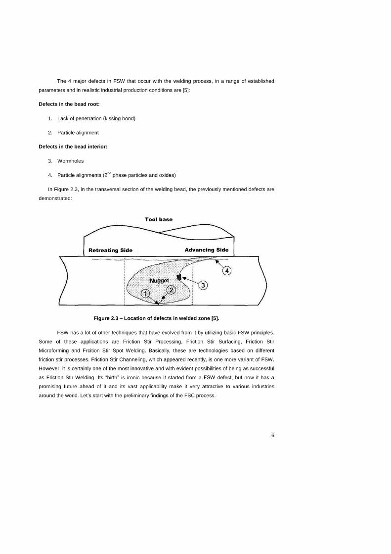
The 4 major defects in FSW that occur with the welding process, in a range of established
parameters and in realistic industrial production conditions are [5]:
Defects in the bead root:
1. Lack of penetration (kissing bond)
2. Particle alignment
Defects in the bead interior:
3. Wormholes
4. Particle alignments (2nd
phase particles and oxides)
In Figure 2.3, in the transversal section of the welding bead, the previously mentioned defects are
demonstrated:
Figure 2.3 – Location of defects in welded zone [5].
FSW has a lot of other techniques that have evolved from it by utilizing basic FSW principles.
Some of these applications are Friction Stir Processing, Friction Stir Surfacing, Friction Stir
Microforming and Frcition Stir Spot Welding. Basically, these are technologies based on different
friction stir processes. Friction Stir Channeling, which appeared recently, is one more variant of FSW.
However, it is certainly one of the most innovative and with evident possibilities of being as successful
as Friction Stir Welding. Its “birth” is ironic because it started from a FSW defect, but now it has a
promising future ahead of it and its vast applicability make it very attractive to various industries
around the world. Let’s start with the preliminary findings of the FSC process.
Retreating Side Advancing Side
Tool base

7
2.1.1.2 Preliminary Findings of FSC
The defect “wormhole”, mentioned in the previous section, led to the invention of a new
welding process called Friction Stir Channeling (FSC). A “wormhole” occurs when the tool shoulder
contact and the processing parameters are not adequate. FSC was developed by determining, which
were the causes of this defect, so that a proper channel could be obtained instead of a small hole, or
“wormhole”. After determining the corresponding parameters that affect the channel formation, FSC
could now be considered a manufacturing process. FSC is based on making the formation of this FSW
defect into a manufacturing process. FSC will enable concepts such as [6]:
Production of integral channels in plates, dies and permanent moulds.
Incorporation of cooling or heating channels on curved surfaces of a solid component.
Design of single piece heat exchangers.
Mishra has shown that by selecting the optimal processing parameters and reversing the
material flow pattern of FSW, it is possible to produce continuous channels. So, Mishra, was the
inventor of FSC, and created a patent for it in 2005. However, since 2005 this innovative
manufacturing process has evolved considerably, with two authors in particular: Nagarajan
Balasubramanian and Pedro Vilaça.
2.1.1.3 Initial Version of FSC
Following the teachings of Mishra, a PhD student named Balasubramanian developed a “first
version” of FSC, and its main aspects are [7]:
The profiled tool is rotated such that the material flow is upwards towards the tool shoulder
An initial clearance is provided between the shoulder and the workpiece, where the material
from the base of the probe is deposited; and
This distance between the tool shoulder and the workpiece can be adjusted to control the
shape, size and integrity of the channel.
Throughout the FSC process, an upward force is generated by rotating a right-hand threaded tool
clockwise (or a left-hand threaded tool counter-clockwise). A channel is formed due to a separation of
the plasticized material around the probe with the plasticized material under the base of the probe.
The material around the probe moves upwards owing to the rotation of the probe and the orientation of
the threads, and it is deposited on the top of the nugget underneath the shoulder surface. The
clearance between the shoulder and the workpiece enhanced the formation of the “wormhole” defect.
Owing to the fact that, this defect occurred due to bad shoulder contact, this clearance was essential

8
for the channel formation. Another aspect of FSC, which enhanced the channel formation, was the aid
of the rotation in the opposite direction of the one performed in FSW. All of these factors enabled the
production of a continuous channel with any size, depth or path within the FSC tool limits. Hence, the
shape and size of the channel can be controlled by varying the following parameters [7]: the clearance
between the workpiece and the tool shoulder, the tool rotation speed, the tool travel speed and the
tool design.
Balasubramanian et al. [7] have also discussed and demonstrated the applicability of the FSC
concept to create continuous channels along linear and curved profiles, as well as the possibility of
manufacturing Mini-Channel Heat Exchangers (MCHX). The high flexibility and low production costs of
this innovative manufacturing process provide this technology with a great potential to be successfully
introduced in various industries. However, FSC still needs to have a considerable development to
prove its industrial applicability.
2.1.1.4 Development of FSC
Recently, in Instituto Superior Técnico (IST), FSC was patented and re-invented by Pedro
Vilaça and Catarina Vidal, being the referred patent: Modular adjustable tool and correspondent
process for opening continuous internal channels in solid components, national patent pending N.º
105628 T on April 15 of 2011 [8]. An evolution of the FSC tool was developed, which enables the
material removed by the process to be cleared out as the channel is being produced leaving the
workpiece with the same level and surface finish as it had before the channel was produced. The
major step given by P. Vilaça et al. in the development of FSC reinforces the great potential of this
manufacturing process in industrial applications such as the automotive, aerospace and railway
industry, as well as conformal cooling systems and heat exchangers, as it was mentioned by
Balasubramanian et al. The strong potential and vast applicability of FSC will be demonstrated, and
proven, throughout this work.
Balasubramanian et al. [7] stated that the presence of the gap between the shoulder and the
workpiece was a major difference between the FSC and the normal FSW or Friction Stir Processing
(FSP). It is important to recognize that FSW and FSP are performed with the bottom of the shoulder in
contact with the workpiece, to generate the forging action required, to produce defect free welding or
processing. However, the “new version” of FSC produced in IST by P. Vilaça et al. suggests some
modifications from FSC initial version of Balasubramanian:
No initial clearance is provided between the shoulder and the workpiece, so the material from
the base of the probe is deposited on the sides and back of the shoulder (to create the
channel).
The main parameters of the process (tool travel speed, tool rotation speed, size of probe and
shoulder) can be adjusted to control the shape, size, and integrity of the channel.
Comment [U1]: SWOT analysis

9
Recent developments made by P. Vilaça et al. [8] promoting distinct material flow, where a
controlled amount of material from the workpiece, flows out from the processed zone and ends up
producing the internal channel. However, the material flowing from the interior of the solid workpiece is
not deposited on the processed surface but directed outside of the processed zone in the form of toe
flash. The scrolls on the tool shoulder enable this material flow from under the shoulder to the
periphery of the processed zone. The position and size of the channels can therefore be controlled
and the processed surface is left at the same initial level. It is also possible to integrate in the tool, a
surface finishing feature. The Friction Stir (FS) channels result from the application, in the visco-
plasticized workpiece material, of an upward action along the threaded probe combined with an
outward action along the scrolled shoulder. The FSC process can be controlled by selecting the
adequate processing parameters.
Figure 2.4 – Schematic representation of FSC “new version” process (cross section view) [9].
Summarizing, the material that comes from the base of the probe is pushed outwards by the
scrolls on the shoulder because there is no clearance between shoulder and workpiece. This major
difference also has an impact on the characteristics of the channel: size, shape, roughness and
mechanical properties, compared to the FS channels produced by Balasubramanian. The
development made by P. Vilaça et al. created this “new version”, which allows FSC to have channels
of greater dimension, rougher surfaces and bigger “wet surfaces”. Consequently, all of the mentioned
features enable more industrial applications for FSC. Nonetheless, it is essential to understand how
these continuous channels are developed, to realize how easily the channels can be produced.

10
2.1.2 The Channel Formation
The production of a FS channel can only be fully understood, by analyzing the zones of a
channel’s transversal cross section. Figure 2.5 shows the transversal cross section of a FS channel
manufactured in IST.
Figure 2.5 – Example of a cross section macrograph of a FS channel showing channel (Ch),
nugget (N), base material (BM), advancing side (A.S.) and retreating side (R.S.) localization [9].
The nugget (N) demonstrates the material flow pattern during the process, after the tool has
passed over the region. The direction of the tool rotation is counter clockwise and the travel direction
is outside from the plane of the paper’s front side. To understand the channel formation, it is
necessary to distinguish among the different regions of the channel cross section, which are
demonstrated in Figure 2.5. The nugget consists of the stirred zone and the channel below; its limits
are defined by a black line in Figure 2.5. The base material (BM) is the unprocessed parent material
that did not have its properties altered [9]. Obviously, in order for a channel to be formed, material
must be removed from the stirred zone. Due to the orientation of the probe threads and the direction of
the tool rotation, the plasticized region at the bottom of the channel is pushed upwards on the
advancing side (the side where the velocity vector of the tool rotation has the same direction as the
travel direction), represented by A.S. on Figure 2.5. The upward force produced by the probe threads
obliges the plasticized material to be pushed upward. After being pulled upward, the stirred material is
then pushed outwards by the scrolls of the shoulder in the “new version” of FSC. Another important
difference to the initial version of FSC is that this process of pulling material upwards is aided by the
vertical downward forging force that creates a pressure on the nugget and helps the channel to be
compact and also enhances the material flow. This major difference explains the upgrade that having
no clearance between the shoulder and the workpiece represented to the FSC developed by P. Vilaça
et al. Owing to the shoulder rotation and shoulder base design, the material in the upper region of the
workpiece is pushed inward and deposited mainly on the retreating side (R.S.). A further distinction in
the conditions of the process is that better results are obtained with “colder” conditions. An additional
layer surrounds the nugget, as a thermo-mechanically affected zone (TMAZ), where the amount of
grain refinement is insignificant. TMAZ is unclear in Figure 2.5.

11
On the other hand, in the FSC version of Balasubramanian et al. the material that is pulled
upwards by the threads and the tool rotation is deposited in the clearance between the shoulder and
the workpiece. Consequently, the material is not deposited around the shoulder, but instead under the
shoulder. In this case, the material that is being pulled is not assisted by the downward forging force,
once again due to the gap between the workpiece and the shoulder. The absence of this aid reduces
the quantity of material that is pulled by the threads, which ends up being significantly less. As a
result, the channels from the two “versions” tend to be different in shape and size.
As any other manufacturing process, FSC is not defect free. Consequently, after various tests
and thorough analysis, a range of process parameters was developed, where continuous and stable
channels were created repeatedly. In this case the defects in both versions were slightly different but
the concept ended up being similar. In the initial version of Balasubramanian, two types of defects
were determined: defective channels (open channels) or discontinuous channels were observed when
the process parameters were outside the optimal process range. Open channels were created when
the processing conditions were extremely colder and this could be due to the inadequate flow of
material from the probe base to the shoulder region and the extruded material being insufficient to fill
the shoulder-work material clearance. This leads to a situation where the shoulder is unable to
process the material and distribute it evenly over the top of the channel, which results in the non-
closure of the flow arm along the advancing side [10], and an open and defective channel.
Discontinuous channels were created when the processing parameters were hotter and outside the
optimal zone.
The same situation happens with the “new version” of FSC. When the process parameters are
outside a certain range, open or discontinuous channels are created. Colder conditions, in other words
low heat indexes, caused defects more easily. On the other hand, when producing channels with
hotter conditions the most common problem was the probe breakage. Discontinuous channels almost
never occurred, due to the fact that the FSC performed by P. Vilaça et al. apparently removes more
material than the one executed by Balasubramanian. Consequently, there is always enough material
removed throughout the whole process to produce a channel, even if it is smaller than usual. An
optimal zone for this new version of FSC was also created. C. Vidal and P. Vilaça obtained specific
process parameters, which optimized the manufacturing process. However, three main reasons can
be defined until now for discontinuous channels in this “new version” of FSC:
1. Tool travel speed
2. Shoulder pressure
3. Base material (actual substrate)
Later on, in the current work, the different FSC conditions will be discussed with the process
parameters that were already established.

12
2.1.3 The Channel Shape
The differences in the FSC process between the two versions also caused a consequent
difference in the channel shapes. The shape of the channel obtained from FSC initial version is closer
to an ellipse or oval shape. The author stated that the channel shapes usually vary nonlinearly with the
process parameters (the tool rotation speed and tool travel speed). Figure 2.6 shows the variation of
the channel shape by changing the process parameters in the FSC initial version. As it can be
observed in Figure 2.6, including (a) and (b) below, the channel produced with a high heat index
process condition is visibly well-structured as compared with the channel from the lower heat index
process condition. In this case, Balasubramanian [7] defined heat index as a relative term defined as
the ratio of the square of the tool rotational speed to the tool travel speed. This ratio is used as a
representation to differentiate the various processing conditions. For a high heat index run, the volume
of material displaced from the probe base is high due to the high tool rotation speed, or alternatively, a
low travel speed. Another aspect that can be easily spotted in the channel shape is the shape of the
channel side walls, which are clearly influenced by the probe features.
Figure 2.6 – Cross section showing FS channel shapes produced by Balasubramanian with
different processing parameters: (a) 1100 rpm, 2.11 mm/sec, and (b) 1100 rpm, 2.96 mm/sec [7].
Table 2.1 – Variable parameters of FS channels produced by Balasubramanian [7].
FSC Condition
Tool rotation speed (rpm)
Tool travel speed (mm/sec)
Tool travel speed (mm/min)
Heat Index (rpm
2/(mm/min))
(a) 1100 2.11 126.6 9557.7
(b) 1100 2.96 177.6 6813.1
Table 2.1 was built to demonstrate the difference in heat indexes of the two runs. The heat
index is a parameter that aids in determining the stress, or harsh conditions, the probe and the
workpiece are going through in the process. A major feature in FSC is the heat up of the FSC tool. As
the FSC tool advances and produces the channel, the frictional heat increases at the tool-workpiece
interface making the material that is being processed softer, as well as heating up the probe
considerably. This heat increase is a problem that P. Vilaça et al. have faced in the development of
the FSC process. Balasubramanian et al. [7] stated that “a closer observation of the process forces
and channel shapes show that as the magnitude of the process forces reduces, the shape of the
channel is well-structured. It can be inferred that the shape of the channel is influenced by the

13
downward forging force applied by the shoulder on the material. The magnitude of the vertical force is
low due to high frictional heat. The structural integrity of the channel walls and roof indicates that the
force applied by the shoulder is insufficient to cause them to collapse”. The lack of this downward
forging force was the only defect of the FSC executed by Balasubramanian et al. and that is where the
developments performed by P. Vilaça et al. were critical to solve this technological disadvantage FSC
had. The inclusion of a downward forging force enables FSC to have larger channels with lower heat
indexes, which permits longer continuous channels with less demanding conditions for the FSC tool.
As it was mentioned before, these demanding conditions are concentrated especially on the probe of
the FSC tool, which is subject to harsh conditions and due to its small size, it needs to be made of an
extremely hard and resistant material.
Consequently, some changes were verified in the “new version” FSC, which relies on a
consistent downward forging force. The channel does not have an elliptical or oval shape anymore. In
this case, the shape is more like a trapezoid turned upside down. In contrast with the FSC version of
Balasubramanian, the channel shape does not have significant variations, when produced with
diverging process parameters. Four standard FSC conditions were determined, each with specific
parameters, to demonstrate the influences of the different process parameters on the channel
features. Even with a significant variation of the heat index for each FSC condition, the shape of the
channel does not change abruptly for any of the different conditions.
The process parameters, presented in Table 2.2, were tested and determined by P. Vilaça et
al. [9]. After a thorough analysis, 4 different FSC conditions were defined. These conditions and the
corresponding values will be referred to throughout this section of the work. After Table 2.2, images of
channel cross sections are displayed in Figure 2.7, which correspond to 4 different FSC conditions
that are mentioned in Table 2.2.
Table 2.2 – Different FSC process parameters [9].
FSC Condition
Tool rotation speed (rpm)
Tool travel speed (mm/min)
Heat Index (rpm
2/(mm/min))
A 600 80 4500
B 600 150 2400
C 800 80 8000
D 800 150 4266.7

14
Figure 2.7 – Cross section macrograph showing channel geometries produced with different
FSC processing parameters: (A) 600rpm, 80mm/min., (B) 600rpm, 150mm/min., (C) 800rpm,
80mm/min. and (D) 800rpm, 150mm/min [9].
The channel shape in the “new version” FSC can be attributed to the volume of processed
material that is displaced from the base of the probe for every rotation of the tool and also the
compacting force that is applied on the channel ceiling during the linear forward movement performed
by the shoulder [9]. Nonetheless, a trend can be spotted in the 4 different conditions of the “new
version” FSC. Condition B has by far the smallest heat index, and it has the channel with the least
defined shape. On the other hand, conditions A and D have very similar heat indexes but the channel
ceiling of condition D demonstrates a very irregular surface maybe due to a very large amount of
frictional heat produced and an excessive softening of the workpiece material. A possible cause of this
situation is the elevated value of tool rotation speed, as well as a large magnitude for the tool travel
speed. However, it is clear that the channel shape has small variations compared to the considerable
modification of the process parameters values. In order to standardize the characteristics of the
channel shape and to spot possible trends in the channel shape change with the variation of the
process parameters, two characteristics of the channel were determined by P. Vilaça et al. [9]: the
closing layer thickness (D) and the shear angle (α). In Figure 2.8, these geometric parameters are
demonstrated in a FS channel cross section.

15
Figure 2.8 - Schematic representation of a cross-section (above) and a plan (below) views of
the friction stir channeled solid block [9].
Table 2.3 – Geometric parameters of internal channels produced with different FSC process
parameters [9].
FSC Condition A (mm2) D (mm) α (º)
A 13.49 2.5 13
B 14.01 2.3 12
C 12.75 3.1 13
D 12.88 2.8 14
The closing layer thickness and the shear angle were defined by P. Vilaça et al. [9] for the
“new version” FSC. Both aspects are demonstrated above, in Figure 2.8, for a better understanding of
the preceding analysis. The closing layer thickness results are consistent with those obtained for the
channel area, as it is visible in Table 2.3. In other words, as the channel area increases, the closing
layer thickness decreases. On the other hand, the shear angle has no direct comparison to the values
of channel areas or even with the closing layer thicknesses for the different FSC conditions. The
results obtained are not conclusive for any of the two characteristics. Perhaps, this situation occurred
due to the low amount of samples that were analyzed. Nonetheless, the channel area is always an
important parameter to be analyzed, to understand the actual dimensions of the channels. The
channel dimensions are of great importance to the various industries FSC could be applied to, as well
as to determine its various industrial applications.

16
2.1.4 The Channel Size
In general terms, according to Balasubramanian et al. the channel size depends on the
following [7]: “for any tool, the maximum possible channel area is the maximum volume of material
that can be displaced by the probe at any given instance, over a unit length. The tool with the
maximum surface area of probe features theoretically is expected to generate a channel with the
largest cross-sectional area for a particular plunge depth”.
To prove this principle and to analyze this theory, it is important to demonstrate actual results
of channel areas and compare them with the process parameters. The channel areas for the 4
different FSC conditions, obtained by P. Vilaça et al., are shown in Table 2.4. At first sight, it is
possible to realize that the biggest channel areas correspond to FSC conditions A and B, in
comparison to conditions C and D. However, in both cases for the same tool travel speed, the channel
area increases significantly as tool rotation speed decreases. Taking into consideration a first insight,
in which Balasubramanian [7] considers that the channel area is directly related to the key process
parameters: tool rotation and travel speeds at each plunge depth. In fact, it is possible to verify by
observing Table 2.4 that the channel area decreases with an increase in the tool rotation speed.
Another pattern that can be determined is that for the same tool rotation speed, the channel area
increases slightly with an increase in the tool travel speed.
Table 2.4 – FS channel areas (mm2) for different FSC conditions [9].
FSC Condition A (mm2)
Tool rotation speed (rpm)
Tool travel speed (mm/min)
A 13.49 600 80
B 14.01 600 150
C 12.75 800 80
D 12.88 800 150
In conclusion, the channel size varies a lot, as it is noticeable from the values above. In
agreement with the vision of Balasubramanian, channel size varies due to the same concept. The
variation of the process parameters enables the possibility to vary the channel size. According to the
values of Table 2.4 and the research developed by Balasubramanian et al., it is possible to verify that
the channels obtained by P. Vilaça et al. are significantly bigger in size. In numerical values, the
difference is approximately 10 mm2, from about 13 mm
2 to 3 mm
2. In terms of percentage, it is an
increment of about 330%. However, the channel areas between the two versions are not comparable
due to the different sizes of FSC tools that were used as well as different base materials and process
parameters. A possibility to explain the great difference in the channel size of these two versions is the
application of the vertical downward forging force in “new version” FSC. Obviously, the growth of the
channel size permits a wider range of functions and a larger flexibility to maximize its potential
introduction in the mould or heat exchanger industry, as well as other major industries. P. Vilaça et al.
clearly improved the initial version of Balasubramanian and opened up new doors for FSC.
17
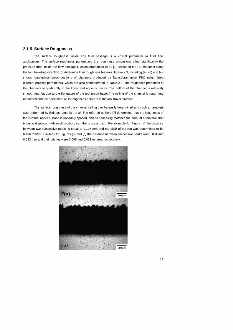
2.1.5 Surface Roughness
The surface roughness inside any fluid passage is a critical parameter in fluid flow
applications. The surface roughness pattern and the roughness dimensions affect significantly the
pressure drop inside the flow passages. Balasubramanian et al. [7] sectioned the FS channels along
the tool travelling direction, to determine their roughness features. Figure 2.9, including (a), (b) and (c),
shows longitudinal cross sections of channels produced by Balasubramanian FSC using three
different process parameters, which are also demonstrated in Table 2.5. The roughness properties of
the channels vary abruptly at the lower and upper surfaces. The bottom of the channel is relatively
smooth and flat due to the flat nature of the tool probe base. The ceiling of the channel is rough and
undulated and the orientation of its roughness points is in the tool travel direction.
The surface roughness of the channel ceiling can be easily determined and such an analysis
was performed by Balasubramanian et al. The referred authors [7] determined that the roughness of
the channel upper surface is uniformly spaced, and its periodicity matches the amount of material that
is being displaced with each rotation, i.e., the process pitch. For example for Figure (a) the distance
between two successive peaks is equal to 0.107 mm and the pitch of the run was determined to be
0.106 mm/rot. Similarly for Figures (b) and (c) the distance between successive peaks was 0.091 and
0.033 mm and their pitches were 0.095 and 0.032 mm/rot, respectively.

18
Figure 2.9 - Longitudinal cross section of a FS channel conducted by Balasubramanian
showing the roughness on the channel ceiling produced with the following process
parameters: (a) 1200 rpm, 2.11 mm/sec, (b) 800 rpm, 1.27 mm/sec, (c) 800 rpm, 0.42 mm/sec [7].
The heat indexes, as well as the process parameters, of these three trials performed by
Balasubramanian et al. are the following:
Table 2.5 – Heat indexes of three FSC trials performed by Balasubramanian.
FSC Condition
Tool rotation speed (rpm)
Tool travel speed (mm/sec)
Tool travel speed (mm/min)
Heat Index (rpm
2/(mm/min))
(a) 1200 2.11 126.6 11374.4
(b) 800 1.27 76.2 8398.95
(c) 800 0.42 25.2 25396.8
A major difference between the two versions of FSC is the value of the heat index during the
manufacturing process. These three runs that were performed to demonstrate the roughness features
of channels manufactured by Balasubramanian, reinforce the high values of heat indexes used by the
“old version” FSC. Having a higher heat index means working in hotter conditions, which also means
higher fatigue on the materials and higher demand on the FSC tool. Once again, this is another proof
that P. Vilaça et al. developed some disadvantages of the FSC process and had a major contribution
on the evolution of this innovative technology.
Figure 2.10 shows the longitudinal cross sections of a channel produced using the FSC
executed by P. Vilaça et al. In this case, the channel in Figure 2.10 was produced using FSC condition
B parameters. The upper surface of the channel (channel ceiling) is rough and wave shaped and the
orientation of this surface roughness points to the direction of the tool linear movement.

19
Figure 2.10 - Longitudinal cross sections of a channel produced in FSC condition B
(ω=600rpm; v=150mm/min) showing the roughness on the retreating side (a) and on the
advancing side (b) of the channel [11].
However, in discordance with Balasubramanian the channel side walls present different
roughness characteristics. The channel advancing side (shear side) does not exhibit any significant
roughness comparing to the retreating one. First of all, the bottom of the channel is relatively smooth
and flat due to the flat nature of the tool probe base, as it was mentioned by Balasubramanian et al.
Figures 2.11 and 2.12 present cross sections of the “new version” FSC, which were obtained by P.
Vilaça et al. to determine the roughness properties of the side walls of the FS channels. It is possible
to observe in Figure 2.11 that, for the same tool travel speed, the roughness of the retreating side is
similar, i.e. FSC conditions A and C present similar roughness conditions in the retreating side, as well
as conditions B and D. Consequently, the same logic is applied to Figure 2.12. In Figure 2.12 it is
visible that, for the same tool rotation speed, the ceiling has similar roughness characteristics [11].
Figure 2.11 - Cross section showing the roughness on the bottom and on the retreating side of
the channel at 4 different FSC (conditions A, B, C & D) processing parameters [11].

20
Figure 2.12 - Cross section showing the roughness on the ceiling and on the advancing side of
the channel at 4 different FSC (conditions A, B, C & D) processing parameters [11].
According to Balasubramanian et al., the channel side walls do not show any roughness
properties along the length of the channel. On the contrary, the IST version of FSC has different
results in terms of surface roughness, in certain aspects. Obviously, the lower surface is also flat due
to the flat surface of the probe base, but the lateral walls demonstrate certain roughness
characteristics. One of the walls, the advancing side one, presents a flat surface, very similar to the
bottom of the channel. However, the retreating side wall has a random surface roughness that will
increase the pressure drop and consequently enhance the heat transfer from the liquid flowing inside
the channel and its surroundings. Once again, an improvement to FSC caused by P. Vilaça et al.,
which can be of major relevance in any industrial application that involves heat transfer. A specific
example of that are the mould and heat exchanger industries. However, the industries are very exigent
in terms of mechanical properties of its products.
2.1.6 Mechanical Properties
The mechanical properties of the FS channels are an important feature of this manufacturing
process, to ensure a sustainable introduction into the industry. Following this logic, the influences of
the processing conditions on the bending and internal pressure resistance of the channels were
analyzed by P. Vilaça et al [9]. The referred author studied the influences on the mechanical
properties of the channel by varying the tool rotation speed and the tool traverse speed. A patented
modular concept of a FSW tool that enables internal forced refrigeration was used to produce all
channels. This tool is based on three main components: body; shoulder and probe. It was selected, for
all the runs, a conical probe with a 5mm bottom diameter and left-handed threads along its length and
a plane shoulder with two spirals striates scrolling an angle of 360º with outer and inner diameters of
20mm and 9mm, respectively. In-plane bending tests were carried out to two types of channels:
transversal and longitudinal. The span distance (distance between the centers of support rolls) was

21
59mm. Support rolls diameter was 10mm and mandrel radius was 5mm. Mandrel velocity used
throughout the trial was 1mm/min. From each condition two specimens were taken and bended. The
base material and three different conditions of FS channeled specimens were tested: (x) specimens
with a transversal channel with the processing zone (channel ceiling) under tensile stress, (y)
specimens with a longitudinal channel with the processing zone (channel ceiling) under tensile stress
and (z) specimens with a longitudinal channel with the non-processing zone (channel bottom) under
tensile stress. All mechanical trials were performed at room temperature. The values listed in Table
2.6 were determined by P. Vilaça et al. [9].
Table 2.6 – Maximum load (kN) results for different FSC conditions [9].
Base Material 76.65
Bending test condition
FSC Condition (x) (y) (z)
A 28.06 53.31 72.44
B 26.40 51.39 72.19
C 34.39 40.49 56.72
D Not tested 40.61 58.69
From the bending tests executed by P.Vilaça et al., it is possible to verify that the tool rotation
speed has a greater influence in the FSC specimens bending strength than the tool traverse speed.
For bending tests, specimens with a transversal channel with the processing zone under tensile
stress, when the tool rotation speed increases the maximum bending load also increases. A specific
fact needs to be mentioned, which is that all of the specimens with a transversal channel fractured at
the advancing side. Figure 2.13 demonstrates the place where the fracture occurred for the
experimental condition (x), which reinforces that the advancing side is the most fragile zone of the FS
channels. According to the bending tests, results of the specimens with a longitudinal channel with the
processing zone (channel ceiling) and with the non-processing zone (channel bottom) under tensile
stress, the channel bottom is more resistant than the channel ceiling.
Figure 2.13 – Fracture localization of specimens tested under bending test condition (x)
referred in Table 2.6 [9].

22
The internal pressure tests performed by P. Vilaça et al. [9] gave surprising results due to the
elevated pressures that FS channels were able to support before leaking points arose. The authors
also concluded that by increasing the tool rotation speed, for the FSC conditions tested, the minimum
pressure that leaking points arise also increases. In this specific case, by comparing FSC conditions C
and A, in other words by increasing 200 rpm and maintaining tool travel speed, the value of the
minimum pressure obtained without any leakage duplicated.
Figure 2.14 - Microhardness profile across the FSC processed zone for FCS condition C
(ω=800rpm; v=80mm/min) [11].
Last but not least, the hardness of FS channels was analyzed. Figure 2.14 shows the micro
hardness profile measured across the cross section of the channel processed zone produced with the
parameters of FSC condition C. It can be seen that the hardness values are higher in the stirred zone
- the channel nugget – in which the higher grain refinement contributes to the increase of hardness.
However, these hardness values are lower than the hardness values of the BM, which is about 194
HV0.5. The overall softening of the processed region is caused by coarsening/dissolution of
strengthening precipitates during the thermal cycle of the friction stir process [7].

23
2.2 Alternative Technologies
FSC is an innovative technology that has high potential to be introduced in various industries
that already have established technologies to perform the same task, FSC is able to perform.
However, FSC has some advantages to these established technologies, but that will be analyzed later
on in this work. First of all, it is essential to acknowledge which are the concurrent technologies of
FSC. The existing technologies that are able to produce continuous internal channels can be resumed
to three main technologies: Drilling, EDM and Milling. Each one of these technologies has its own
advantages and disadvantages, but all of them can be a threat to FSC, therefore they should be taken
into consideration.
2.2.1 Drilling
The main technology established throughout the world as the number one manufacturing
process to perform internal channels in solid blocks is: Drilling. Drilling constitutes about 40% of all
metal-cutting operations. Applications that involve drilling large number of holes encompass industries
such as the aerospace, automotive, and potentially many other industries [12]. Considering this fact,
these same industries would benefit largely from drilling holes at significantly faster rates. Aggressive
drilling can be summarized as combinations of properly set high cutting speed and tool feed resulting
in proportionally large material removal rate. The main benefits of aggressive drilling include higher
productivity, a synergistic effect in reducing the specific cutting power (and drilling forces) while
removing substantial amounts of material. The primary challenges for aggressive drilling include
spindle power, accelerated tool wear, set up rigidity, hole quality, chip evacuation, and high
acceleration/deceleration demands on the spindle drives. It is essential to understand how different
aluminum alloys behave when drilled. These differences include chip formation and tool wear rates.
This includes classifying the work aluminum as both wrought or cast alloy and then sub-classifying to
understand the subtle variations. This situation can be reflected on the evolution of FSC. A complete
comprehension of the material behavior in an innovative is imperative and such an analysis should be
performed for FSC. At this moment, the major difference between drilling and FSC is the speed at
which it produces channels. Nonetheless, drilling can only be performed in a straight path and FSC
can produce a hole with any desired path. If a drill tries to deviate or curve slightly, certainly it will
cause uneven wear in the drilling tool and lose its effectiveness. Drilling has this specific limitation and
FSC can be the solution for that limitation.
Drilling as we know it involves drilling holes of a considerable size. In order to relate drilling to
FSC, it is essential to acknowledge that drilling can be performed in very small holes. Zelinski et al.
[13] suggest that microdrilling is doable and more efficient than EDM hole making and in their
perspective, microdrilling simply requires more care than conventional-size drilling, however hole
straightness is easier to control with drilling than it is with EDM hole drilling. In some cases, the
Comment [U2]: SWOT analysis
Comment [U3]: SWOT analysis
Comment [U4]: SWOT analysis

24
straightness and position of the tiny holes in the workpiece (part) are critical. The holes in the case of
Zelinski et al. can be machined in a comparable critical part with a 0.51 mm diameter and 38.1 mm
deep. When the work material changed from super-alloy to stainless steel, small-hole EDM was
substituted by a small CNC machining center utilizing microdrilling. Clearly, an established quality of
drilling is its reliability in hole straightness and stability. It is also common sense that drilling can be
performed in almost any material, which is still not the case of FSC. However, drilling has other
limitations such as the need to refrigerate the drilling tool due to the growing heat index along the
manufacturing process.
At present, as mentioned before, there is a great deal of discussion about the use of lubricants
in machining. Industry and research institutions are looking for ways to reduce the use of lubricants
because of ecological and economical reasons. Due to high costs, infrastructure demands, and
environmental concerns, there is motivation to move toward dry machining, i.e., machining without the
use of a metal removal fluid (MRF). The rising costs associated with the use and disposal of cutting
fluid have forced engineers to concern themselves more intensively with questions of cooling
technology. While there are established applications of dry turning and milling, dry drilling presents
special difficulties due to the problems of swarf clearance from the drill flutes and consequent heat
build-up and clogging. Aluminum, as used in light-duty engines and transmissions, is particularly
difficult to machine dry because of its tendency to adhere to the tool as the temperature rises.
Machining performance suffers when machining is done without a MRF. For example, tool life during
drilling is reduced from > 10,000 holes/drill with MRF to about 40 holes/drill without a MRF (dry). As
Dasch et al. mentioned the challenge, then, is to reduce the heat build-up through improved
tribological surfaces on the tool. A solution according to the referred authors is to coat the drills with
specific materials. Consequently, their study involved the evaluation of a variety of carbon-based
coatings on drills to determine their performance in both bench and machining tests. The best coatings
gave a significant improvement in performance compared to an uncoated drill [14] [15]. These results,
demonstrate the limitations of drilling to produce long mini channels, which is a process that rapidly
overheats the tool when drilling material like aluminum. The need for specific coatings for each drill is
also another setback owing to the fact that it increases the technological cost. Another important
aspect is the need for MRF in drilling, which is not needed in FSC. The need for technologies that do
not need lubricants is increasing, and FSC can be the solution for this issue, as well as other issues
such as tool wear in conventional drilling techniques.
The temperature generated by friction and plastic deformation in a manufacturing process
strongly controls tool wear. At lower cutting speeds tool wear is not severe as long as the temperature
is not relevant. When the cutting speed is increased, there is a transition in wear mechanisms from
abrasion and/or adhesion to diffusion. The cutting tests performed by Nouari et al. [16], without using
MRF, showed that the best results in terms of maximum and minimum hole diameter deviations and
surface roughness are obtained for the uncoated and coated tungsten carbide drills. The need for

25
coated drills, show the limitations in precision other than its limitations in non linear channel paths. A
different technology that is able to produce channels with any desirable path is EDM.
2.2.2 EDM
Drilling has its qualities, but when holes must be drilled in curved or angles surfaces, great
difficulties arise with conventional drilling techniques. A solution for these difficulties is: EDM drilling. In
EDM (Electrical Discharge Machining) drilling, the electrode never contacts the surface that is being
cut. This non-contact of the tool in the machining process eliminates the tool pressure when drilling on
curved or angled surfaces. The rotating electrode helps in producing concentricity, causing even wear,
and also helps in the flushing process. The high flushing pressure through the center of the electrode
tends to stiffen it. Also, the dielectric fluid being forced out of the hole produces a centering effect upon
the electrode. With the aid of the electrode guide and the flushing effects on the electrode, EDM hole
drilling can penetrate much deeper in higher rates than almost any other EDM drilling method [17].
The process consists of using a precision tubular electrode (generally brass or copper)
mounted into the drill chuck located on the "Z" axis and held in location on top of the workpiece by the
ceramic guide. The top of the workpiece is located and the drilling depth is set. The electrode rotation
is turned on and the deionized (pure) water solution, which is pressurized between 50 and 100 kg/cm2,
is sent through the tubular electrode as a flushing agent [18]. The power supply parameters are set-
which normally consist of on-time, off-time, peak current and amount of capacitance. At this point, the
discharge is turned on to begin the drilling cycle. At the end of the drilling cycle, the discharge is
turned off and the "Z" axis is retracted above the workpiece.
EDM hole drilling is a different variation of EDM processes, such as die sink EDM and wire
EDM. Although EDM fast hole drilling uses the same principles as other EDM methods (as shown in
Figure 2.15), a constantly rotated hollow electrode and pumping of dielectric fluid through the
electrode tube are the two distinct features [19].
Figure 2.15. – EDM hole drilling process schematic demonstration [19].

26
The main difference between fast hole drilling and other processes lies in the use of a high
pressure (70 – 100 bar) dielectric pump. The combination of [20] the high pressure dielectric fluid, the
rotation of the tubular electrode and the high electrode feed rate (controlled by a fast response servo)
make it possible to produce holes at a very fast rate.
The development of EDM hole drilling was eminent, and an example of that were the tests
performed by Yilmaz et al. [21], which involved drilling micro and macro-scale holes (0.4 to 3 mm
diameters) on Ti-6Al-4V and Inconel 718 alloys, which are commonly used in the aerospace industry
and the medical sector for manufacturing of highly critical components. An automated approach for
EDM hole drilling was suggested by the referred authors, which could be an intelligent industrial
application for repair and production of products for the aerospace and medical industry. Although
EDM hole drilling is a variation of an EDM process, it does not use oil-based dielectric and does not
leave toxins. Therefore, EDM hole drilling machines are environmentally-friendly machines, since the
dielectric is usually pure (deionized) water, which opened a lot of application possibilities in the
medical field. Moreover, the automation of EDM hole drilling saves time and material particularly. It
has been alternatively used for making holes in turbine blades, fuel injectors, medical equipments,
plastic mould vent holes and wire EDM starter holes. Consequently, EDM hole drilling demonstrates to
have great advantages in specialized sectors of the industry due to its high precision and flexibility.
The flexibility of EDM hole drilling has been reinforced by Production Machining. Since 2005,
there are 4-axis and 5-axis EDM hole drilling machines that are able to create angled holes for various
different industrial applications such as, cooling and/or exhaust gas holes in turbine rings and blades,
medical prosthetics and instruments, electronic housings and components, laboratory and analytical
equipment, optical instrumentation, and extrusion dies for glass and composite fibers. The rotary axis
is programmed and controlled using a standard CNC machine and can be easily installed on new
machines or easily retrofit to existing machines in the field [22]. The evolution of this technology and
its ability to work with highly resistant materials reinforces its great potential in various industries such
as: medical, aerospace and automotive.
Another aspect of EDM hole drilling is its durability, since it is a very “sensitive” technology due
to the high precision tools it uses. An interesting investigation was performed by Yilmaz et al. [23] to
understand the EDM hole drilling tool wears and its influence on the hole creation. In this study, a
comparative investigation of fast hole drilling of aerospace alloys was done, once again using Inconel
718 and Ti-6Al-4V. An EDM method was performed in order to explore the influence of electrode type
and material, i.e. single and multi-channel tubular electrodes. The comparisons were made from the
results of MRR, electrode wear (EW) and scanning electron microscope (SEM) images taken from the
machined hole surfaces. The experimental results revealed that the single-channel electrodes have
comparatively better MRR and lower EW. However, the SEM images showed that multi-channel
electrodes produce less damage on machined surfaces than single-channel electrodes for both
aerospace alloys. In conclusion, it is beneficial in all desirable circumstances a single-channel
electrode enabling the process to have a reduced tool wear and a larger produced channel.
Comment [U5]: SWOT analysis
Comment [U6]: SWOT analysis
Comment [U7]: SWOT analysis
Comment [U8]: SWOT analysis

27
2.2.3 Milling
Drilling has clearly demonstrated that it is not viable for certain materials, which EDM is able to
machine and possibly another technology: Milling. Sharman et al. [24] stated that when using
commercially available drills with Inconel 718 the resulting hole quality is not sufficient to meet the
requirements of the aerospace industry and therefore secondary processing is required. So, an
alternative other than EDM hole drilling or reaming after drilling, could be mill boring with a standard
milling tool, which appears to have significant potential for improving productivity and reducing costs.
In particular the mill bore technique gave very low surface roughness values down to 0.046 μm Ra
compared to 0.178 μm Ra for reaming. The milling tools used by Sharman et al. [24] were standard
commercially available solid carbide end mills and with the use of circular interploitation the same
milling tool can be used for many different hole sizes and shapes giving further cost savings and
productivity increases compared to reaming (reduced tool changes, less tooling inventory). Sharman
et al. also stated that future work will focus on improving the stability in mill boring as the tool enters to
cut and achieving the same dimensional tolerance that can be obtained with reaming. In this case,
milling is an intermediate technology between drilling and EDM due to the fact that its cost and hole
quality are approximately in between the two other technologies. Firstly, the technological cost of
milling is clearly more expensive than drilling, but not as expensive as EDM drilling. Second, the hole
quality can be determined according to its low surface roughness as well as the amount of damage
performed on the machined surface. Another aspect to take in consideration is that in certain
situations milling in comparison with drilling avoids one more machining process, which is in general
reaming after drilling a hole.
Milling can be beneficial for hole producing due to the low damage that is causes to the
machined surface. In accordance with this statement, Schulze et al. [25] assured that circular milling
and wobble milling are an alternative to drilling because they cause less damage on the machined
surface because they draw the process forces towards the centre of the workpiece. High feed rates
are the major cause of this surface damage, so milling has a setback owing to the low feed rates that
are needed for it to cause less damage. In this case, milling has demonstrated to be an alternative
technology to produce channels, while creating less damage to the manufactured part. Nonetheless, it
is a process that has a low productivity when compared to alternative technologies.
Another type of milling is the helical milling, which for Iyer et al. is an enabling process
technology for machining precision holes in fully hardened AISI D2 tool steel. Taking into
consideration that, conventional drilling of this material is shown to predominantly result in catastrophic
fracture of the cutting edge at the drill periphery due to insufficient wedge angle, which is a geometric
characteristic inherent to drills. Helical milling with negative rake tools corresponds to a robust process
with a significant improvement in tool life (an order of magnitude), and facilitates dry cutting that
represents considerable cost savings and a substantial benefit to the environment, as it was already
mentioned in the Drilling section. Further, helical milled holes are of H7 quality that eliminates the
need for an additional reaming process leading to an important improvement in process productivity
Comment [U9]: SWOT analysis
Comment [M10]: Determine roughness values for FS channels
Comment [U11]: SWOT analysis
Comment [U12]: SWOT analysis
Comment [U13]: SWOT analysis
Comment [M14]: Mais uma vez referencias à rugosidade da superfície, na qual ter valores para a rguosidade dos nossos canais acrescentaria valor ao estudo pois havia um termo de comparação.

28
[26]. The benefit of using milling as a hole producer is obvious if the hole surface quality is a priority,
as well as, if the material is of very high resistance. On the other hand, if productivity rates are a
priority milling is not the solution.
Last but not least, is laser milling, which offers a cost-effective and time-efficient solution for
two different applications. These applications were defined by Pham et al. as manufacturing of a micro
tool and machining of small ceramic components. The latest version of laser milling equipment has
made a leap in finding the solution to a drawback, usually associated with the laser ablation
processes, which now includes the ability to produce vertical walls. Producing vertical walls was until
recently an obstacle for laser milling; a draft angle was unavoidable on all laser-machined structures.
According to Pharm et al., laser milling is capable of processing a large range of materials, which are
not machinable with conventional manufacturing processes, such as normal drilling. Pharm et al. [27]
demonstrated that engineering ceramics can be machined without requiring expensive special tools
and without any limitations on the three-dimensional complexity of the component. Nevertheless, laser
milling is still in its infancy. Laser material interactions are not yet fully understood. Much effort in R&D
of the available laser sources is still needed. Ultrafast lasers are beginning to be applied; they can
offer more precise machining without the thermal damage that accompanies long pulse laser
manufacturing. Most certainly, the development of this innovative technology will continue, but its price
will always be quite elevated compared to other alternative technologies. The ultimate goal of the
various industries around the world is to find a compromise between all of the main variables:
productivity, cost, flexibility and precision.
This global compromise is always very hard to find, the industry makes the call. Therefore, an
important task at a first stage is to define the target industry. Each technology has their target
industries depending on the attributes and characteristics of that same technology they tend to satisfy
certain needs of specific industries. Accordingly, an important step to determine the industrial
applications of FSC is to define its target industries and establish which processes of those target
industries can be replaced or performed by FSC technology.
Comment [U15]: SWOT analysis

29
2.3 Industrial Applications
The development of a technology is always subject to the necessity of the industry. The
potential, or value, of a technology is related to the amount of solutions it can provide to the industry.
The industry is always searching for a better solution or an easier way to solve problems.
Consequently, if a new technology is being developed it is of major importance to analyze which are
its possible industrial applications. In this case, FSC has two main areas of interest in the world
industry: Moulds and Heat Exchangers.
2.3.1 Mould Production
Mould production is part of a major industry, the mould industry, which has massive mould
production all around the world. Two ways of producing moulds, which FSC can be an alternative to
are: Conformal Cooling and Rapid Prototyping.
2.3.1.1 Conformal Cooling
Conformal cooling is a new concept for the production of moulds. The mould production is
performed with a specific configuration of the cooling channels. The refrigerating channels follow the
configuration of the part (workpiece) shape, enhancing the cooling procedure. The influence on the
cooling time and workpiece surface quality is significant and this concept has been growing recently.
Conventional methods for mould cooling involves drilling holes as close to the moulding
geometry as possible. However, Goldsberry [28] stated in his article that this method does not and
cannot address the many complex part geometries that make up various moulds nowadays, making it
difficult - and often impossible - to drill the cooling lines close enough, to cool the mould cavity in a
uniform manner. Conformal cooling has been developed to help address this problem of cooling cavity
steel consistently and adequately and at the same time preserve mould integrity. For this reason,
companies have started since 2010 producing more and more moulds with conformal cooling
technology. According to Goldsberry, by definition, conformal cooling is conforming and contouring the
water channels to cool the cavity in a more effective and uniform manner, regardless of part geometry.
The specific configuration of the channels makes all the difference in the process efficiency. Luckily,
FSC is a technology that is able to produce conformal cooling channels.
Computer simulations have been performed to prove the benefits of this concept. An example
of these simulations is the analysis of virtual models done by Dimla et al. The referred authors [29]
demonstrated that moulds with conformal cooling channels predicted a considerably reduced cycle
time as well as a noticeable improvement in the general surface finishes quality of the part when
compared to a conventionally cooled mould.

30
Non-uniform cooling or long cooling cycle time would result if a poorly designed cooling
channel is adopted. Due to limitations of traditional machining processes, the cooling channel is
usually formed from straight-line drilled holes and only simple shapes are allowed, regardless of the
shape complexity of the part being moulded. According to a melt flow analysis executed by K. M. Au et
al. [30], the more complex shaped cooling channel does provide a more uniform cooling performance
when compared to the traditional method. In consequence, the appearance of injection moulding
defects can be reduced.
During the last few years, supporters of conformal cooling against traditional processes have
documented noteworthy reductions in two of the most important cost drivers of injection moulding:
cooling times and scrap rates. A striking example of success with conformal cooling comes from a
project undertaken by a major laser-sintering supplier in Germany. The supplier created a tool insert
that incorporated conformal channels to boost coolant flow at hot spots in a mould for manufacturing
low-volume plastic parts (40,000/year). Here are the results of that project [31]:
• The first savings was in the cost of the new insert: €3250 vs. €19,444 for a traditional insert.
• Then there was the cycle time cut of 55%, from 90 to 40 seconds.
• Finally, the two cost reductions together resulted in an amortization time for the insert of only two
months.
It is clear that conformal cooling channels can reduce significantly cycle times for injection moulding
processes. FSC is the adequate solution to produce conformal cooling channels due to its low cost,
high productivity and unique capability of producing channels with any desirable path.
A noteworthy reduction in production cycle time causes a significant reduction in production
costs. The industry is constantly searching for solutions to reduce production costs as much as
possible. FSC can be a solution to produce conformal cooling channels for moulds at a low cost.
However, the wide range of channel sizes and lengths that FSC can manufacture, it can also be a
threat to a technology that has been developing recently, which is Rapid Prototyping.
2.3.1.2 Rapid Prototyping
Rapid prototyping (RP) is a technology that manufactures conformal cooling channels.
However its main limitation is the type of materials that it is able to process. Since, it is a very
“sensitive” technology; it can only use materials that are not of great use to mould industries, for now.
However, in a futuristic perspective RP could be an alternative technology for FSC.
In fact, Gorni states that the time economy and costs savings obtained by applying the rapid
prototyping techniques in building models is about 70 to 90%. However RP is not perfect. The volume
of the prototype is generally limited to 0,125m3 or even less. It is still difficult to make prototypes made

31
of metal; however that will change in the near future with technological development. At the moment,
the conventional machining techniques are still more economic than RP in the case of models made of
metal. Summarizing, all processes of RP have five basic steps [32]:
Creation of a Computer-aided design (CAD) model of the workpiece that is being projected;
Conversion of the CAD archive into Standard Tessellation Language (STL) format, proper for
stereolithography;
Slicing of the STL archive in thin transversal layers;
Physical construction of the model, piling up slice by slice;
Washing and implementing surface finish to the prototype.
These 5 basic steps are important to acknowledge, understanding that RP is a specific and
expensive process, which can reach a great level of detail. In some cases, it is not used because of its
costs and level of expertise. For instance, FSC could be a cheaper alternative when the project budget
is not that high. Even though, FSC is not as precise as RP, it is always a manufacturing technology
that can produce very small conformal cooling channels with a considerable precision.
The mould industry would largely benefit from the usage of RP models. There are three simple
steps that can be implemented into the mouldmaking process, which will increase the mouldmaking
power of the business, avoiding the pains of making unnecessary mistakes. There are three powerful
steps to improve mouldmaking power and those who have implemented these steps are well on the
way to becoming the ultimate toolmakers in their industry. These steps are [33]:
1. STEP 1: Start at Zero - Have the engineer send a model made from a RP process that uses
stereolithography (SLA), selective laser sintering (SLS) or fused deposition modeling.
2. STEP 2: Buy the insurance – From the beginning have a RP model produced, so the tool
designer can understand the geometry of the part or its unique features. A RP model allows a
complete understanding of the part—by holding it in the hands. This provides the insurance
needed to keep the project on schedule and under budget by eliminating future problems.
3. STEP 3: Provide Clarity throughout the Process - A real RP model that travels with the project
through the program allows the mouldmaker to see what is expected and be able to provide
valuable feedback very early in the process.
The new rapid prototyping process proposed by Karunakaran et al. combines Layer
Manufacturing (LM) and conventional machining methods in order to exploit their benefits and avoid
their limitations. LM technologies are also often referred to as RP technologies. In manufacturing, one
uses a fast roughing process followed by one or more finishing processes that are slow but accurate.
The methodology adopted in the proposed RP process also uses this concept of two-level processing,

32
such as, near-net building of the layer and net-shaping it by high-speed machining. This will result in
producing parts and tools economically, accurately and rapidly. The process does not pose any
restriction or loss of accuracy on the prototype as its size grows. Since the size of the part is limited
only by the traverse available on any existing CNC machine, a larger CNC machine can be used to
produce larger prototypes [34]. The evolution of RP is obvious and this only occurs owing to the great
potential RP has to add value to the design of a mould. Hopefully, RP will be an example in the mould
industry for FSC to follow as a technology that adds value to the complexity of mouldmaking and
heating/cooling channels configurations.
It is always important to understand where the technology started and how it grew. "Time to
Market" was originally the strongest inspiration and economical driving force in RP. RP (or LM)
technologies shorten the product life cycle and build up interest. Virtual modeling largely fulfils these
needs and is in continuous rivalry with RP. On the other hand, this conflict increases the interest and
chances of RP processes as alternative or autonomous manufacturing processes and elevates the
interest. The production of long-term usable components and tooling increases the interest in LM [35].
RP has everything that is needed to keep evolving and “step up the game” to stop competing just with
virtual modeling but to produce actual components that will eventually be part of a manufacturing
process.
It is a fact that rapid prototyping has gained a very wide acceptance over the last decade, with
an estimated production of 3.55 million models and prototypes in 2001 and a steady growth of about
20% per year, sales of 1000-1500 machined a year over the last 5 years and about 400 RP service
bureaus worldwide offering RP services. The market of rapid tooling (i.e. the first application of rapid
manufacturing for direct and fast production of tools) is still limited, but has nevertheless found
numerous real applications for the production of soft tools (for limited series) and hard tools (e.g. SLS
tools for series up to 100.000 shots). As for real direct rapid manufacturing (RM) of products, its
application is still in its infancy, even though very promising. The real breakthrough of RM will mainly
depend on cost and productivity improvements, which have to be accompanied with further technical
progress in material properties and most of all in accuracy and reliability [35]. FSC is in a very similar
position in terms of technological development. The cost of FSC is substantially lower, but it is not as
precise as RP. As always, the question is: what are the industry needs? If the prototype does not have
to be that precise and production costs are limited, FSC would be the adequate solution. On the other
hand, if precision is a priority, RP would be the most appropriate technological solution.
Conformal Cooling and Rapid Prototyping are two techniques used nowadays in the process
of mould production that, in some particular cases, can be replaced by FSC. FSC has the capability of
creating conformal cooling channels for normal size moulds. Alternatively, FSC is also able to
manufacture conformal cooling channels for prototypes, which signifies the ability to substitute rapid
prototyping in the mould production procedure. Other than mould production, FSC has the potential to
produce channels for heat exchangers due to its competence in producing internal channels with
significantly reduced sizes.

33
2.3.2 Heat Exchanger Production
The generation of a continuous internal channel by FSC has the potential to open a wide
range of applications in the heat exchanger industry. Heat exchangers are devices that are used to
transfer thermal energy between two or more fluids, or between a solid surface and a fluid, at different
temperatures and in thermal contact. Typical applications of heat exchangers involve heating or
cooling of a fluid stream and evaporation or condensation of fluid streams, with an objective to reject
or recover heat. Heat exchangers are usually classified on the basis of the transfer process, as either
direct contact type or indirect contact type. The heat exchangers are also classified on the basis of the
number of process fluids, or on the basis of the construction or flow arrangements or the heat transfer
mechanisms. Another basis for classification of the heat exchangers is on the basis of surface
compactness. The main objectives of compact heat exchangers are to maximize the efficiency of a
heat exchanger and also to reduce the size of the heat exchanger for a given duty. Compact heat
exchangers are generally used in industry, especially in gas-to-gas or liquid-to-gas heat exchangers.
For example, vehicular heat exchangers, condensers and evaporators in air-condition and
refrigeration industry, aircraft oil-coolers, automotive radiators, and intercoolers or compressors [36].
FSC has the ability to produce the channels for any of these types of heat exchangers, which
demonstrates the elevated applicability it has in the various industries.
The industrial heat exchangers can be classified according to their channel sizes (hydraulic
diameters) and their heat transfer area density. In general, as the size of flow channels employed in
heat exchangers decreases, its heat transfer area per unit volume increases. According to Wadekar
[37], the channel size and the area density are two interrelated parameters, which reflect the
compactness of a heat exchanger and enable a classification of industrial heat exchangers as it is
illustrated in Figure 3.16.
Figure 2.16 – Broad classification of industrial heat exchangers based on heat transfer area
density and channel size [37].

34
The classification of heat exchangers is essential to differentiate the different types of heat
exchangers that are used in the industry. The same thing occurs with channels and consequently the
channel classification. Taking into account that mini-channels are defined as channels in the diameter
ranges of 200 µm–3 mm, most of the refrigeration heat exchangers can be classified as mini-channel
heat exchangers (MCHX). The surface area and heat transfer coefficient enhancements associated
with mini-channel flow can be exploited effectively to make the refrigeration equipment smaller in size.
Significant refrigerant charge reductions are also possible due to the higher surface area-to-volume
ratio for the mini-channels. This ratio comparing the surface area of a channel compared to its volume
is another aspect of FSC that boosts its potential in industrial applications. Since the shape of the FS
channels is a sort of a rhombus its surface area-to-volume ratio is greater than the traditional circle
shaped channels produced all around the world for heat exchangers. Additional advantages of MCHX
include capital cost reductions, reduced environmental impact due to lower refrigerant inventory, and
possible improvements in the Coefficient of Performance (COP) of the system. The MCHX currently
being considered for refrigeration applications are modeled after the existing heat exchangers in
automotive applications [38]. FSC has potential to produce MCHX and the transfer of this technology
to the automotive industry is one of the goals to achieve, where a great variety of MCHX is used at an
elevated cadency.
Mould and heat exchanger production are the two main production industries for FSC to
penetrate. Nonetheless, FSC supported by successful application in the previously mentioned
industrial applications, could in the future, acquire innovative industrial applications in many other
industries, such as the aerospace, defense (military) and biomedical, following the widely known
successful steps of the FSW technology.
2.3.3 Other Applications
During the last decade, the defense and aerospace sectors have taken the lead in
implementing FSW. Recent advances in probe-tool designs and optimized processing parameters
have enabled FSW and Friction Stir Spot Welding (FSSW) applications in the marine, ground
transportation, and automotive industries. Further innovations in low-cost equipment and the
development of industry standards, design guidelines, and a trained workforce will enable the
introduction of FSW and FSSW into the broader light manufacturing, heavy manufacturing, and
construction industries during the next decade [39]. Possibly the projection of Friction Stir Channeling
will be the same in the near future, however FSC is very recent and it is being developed on a daily
basis in Instituto Superior Técnico by Pedro Vilaça and Catarina Vidal. For now, it reveals a great
potentiality and flexibility to be introduced in various industrial applications. The present work
contributes to this goal by increasing the knowledge on the FSC process and technology as well as to
make the connection between the FSC concept and the actual industry along with its corresponding

35
needs. An important aspect for the evolution of FSC is to determine how it can be beneficial compared
to alternative technologies in the industry that already produce internal channels.
The aim of the present work is to demonstrate that Friction Stir Channeling has the capability
and potential of producing conformal cooling channels for different types of moulds by analyzing
opportunities and strengths FSC might have compared to the already referred, existing alternative
technologies. An interesting investigation that will be performed in this work is to develop a competitive
analysis with alternative technologies and afterwards demonstrate the unique advantages inherent to
FSC with a detailed description of the design process and technological implementation of actual
prototypes. The completion of these Case Studies is a material proof of the actual capabilities of the
FSC technology. In addition to that, the prototypes developed in the present work illustrate the
possible industrial applications of FSC, which provides it with a tremendous potential to be an
alternative for technologies such as drilling, EDM and milling.

36
3 Competitive Analysis with Alternative Technologies
Three different Strengths, Weaknesses, Opportunities and Threats (SWOT) analyses were
performed comparing Friction Stir Channeling with three alternative technologies to determine the
strengths and weaknesses of this emerging technology. The SWOT analyses also facilitate an easier
comprehension of the possible opportunities and threats FSC has in terms of external factors
compared to the existing technologies in the industry.
The three main existing technologies in the industry that produce internal channels, or holes,
in the various industries around the world are: Drilling, EDM and Milling. Therefore, a SWOT analysis
comparing FSC and each of the three referred technologies was elaborated to determine the precise
advantages FSC has in relation to each of these technologies as well as the disadvantages that it
presents. Some more relevant data that can be obtained from a SWOT analysis are the external
factors that involve the opportunities and threats FSC has compared to the other three alternative
technologies. These factors provide clues on the adequate path FSC technology should take to be a
successful internal channel producer in various industries.
The three SWOT analyses elaborated in the current work can be applied to any industry in
which FSC could add value to the state of art technology. Even if small adaptations are needed, it will
only aid in identifying specific strengths and weaknesses of FSC compared to presently used
technologies as well as the external opportunities and threats it will face if the industrial
implementation is taken forward.
A final discussion on the main conclusions obtained from the competitive analysis with
alternative technologies, was elaborated. The major aspects to take in consideration were discussed
to determine the key points to focus on, for a successful start in the process of finding adequate
industrial applications that supply added value to the industry compared to the already established
technologies.

37
3.1 FSC vs Drilling
Drilling is the number one hole making technology all over the world, due to its low cost high
productivity and simple process. However, when it comes to drill a hole, its path has to be straight.
The major difference between FSC and drilling lies on the path of the hole (channel). FS channels can
have any desirable path and still be a very low cost technology. Another relevant aspect that
differentiates both of these technologies is that with FSC, the size of the channel can vary along its
path. In the near future, with FSC tool evolution a variation in channel depth along its path will also be
possible and doable.
Opportunities:
Higher productivity
Conformal Cooling
Threats:
Low know how of FSC
Surface finish (Very rough) of the internal channel and of the processed surface
Strengths:
The channels can have any path
The dimension of the channel may vary along its path
Bigger S/V of the internal channel due to shape of the cross section. (square vs. circle) and its high roughness
FSC can produce better (higher
quality) components with higher productivity
Determine if variation of channel dimension along the path is beneficial for heating/cooling system
Faster production cycles due to elevated heat power transfer
Gain know-how Determine
importance/ make use of surface roughness and different cross section shape
Benefits support tests for better know how
Weaknesses:
FSC needs access from one surface
The channels cannot have start and end in the same position
Open hole at the end of the channel path
Range of materials used (only non ferrous) due to budget
Channels can´t reach lateral walls of the mould
Determine if technology
restrictions may affect the productivity (limitation to reach lateral walls, processing surface only contrary to moulding surface)
Drilling of lateral wall is needed and closing processing surface may keep good productivity
Conformal cooling may not be affected by different start/end position
Use the residual open hole at the end for “racord”
Appropriate materials for the tools may permit FSC to be done on other materials (≠AA)
Tested with other
materials but for now focus on aluminum
Determine if hole at the end of channel is a problem for mould
Determine if the channels can be made on the surface contrary to the moulding surface
Finishing of processed surface applied during FSC (in-process)

38
3.2 FSC vs EDM
The major difference between FSC and EDM is the production costs. Both FSC and EDM can
produce internal channels with any desirable path. Other than the difference in production costs, the
need to use a coolant of the EDM technology is a disadvantage compared to FSC. In the case of
industrial application such as mould or heat exchanger production, FSC can produce internal channels
in a solid block.
Opportunities:
Higher productivity
Conformal Cooling
Lower cost
Threats:
Low know how of FSC
Surface finish (Very rough) of internal channel and processing surface
Strengths:
The channels can have any path
The dimension of the channel may vary along its path
Bigger S/V of the internal channel due to shape of the cross section. (square vs. circle) and high roughness
Non consumable tool
No coolant needed
FSC can produce better
components (higher quality) with less cost and higher productivity
Faster production cycles due to higher heat power transfer
Higher tool life and environmentally friendly
Determine if variation of channel dimension along the path is beneficial for heating/cooling system
Benefits support
tests for better know-how
Determine importance/ make use of surface roughness and different cross section shape
Weaknesses:
FSC needs access from one surface (processing surface)
The channels cannott have start and end in the same position
Open hole at the end of the channel path
Small range of materials used due to budget
Channels can´t reach lateral walls of the mould
Determine if technology
restrictions may affect the productivity (limitation to reach lateral walls, processing surface only contrary to moulding surface)
Drilling of lateral wall and closing processing surface may keep good productivity
Conformal cooling may not be affected by different start/end position
Use the residual open hole at the end for “racord”
Appropriate materials for the tools may permit FSC to be done on other materials (≠AA)
Tested with other
materials but for now focus on aluminum
Determine if hole at the end of channel is a problem for mould
Determine if the channels can be made on the surface contrary to the moulding surface
Finishing of processing surface applied during FSC (in-process)

39
3.3 FSC vs Milling
The major difference between FSC and milling is that FSC can produce internal channels and
milling can only manufacture open channels. In the case of industrial applications such as mould or
heat exchanger production, FSC can produce internal channels in a solid block in one single run. On
the other hand, milling creates open channels and to produce internal channels for moulds and heat
exchangers it needs to produce the channels in two runs (steps) in two different workpieces and then
subsequently braze the two pieces.
Opportunities:
Higher productivity
Conformal Cooling
Lower cost
Threats:
Low know how of FSC
Surface finish (Very rough) of internal channel and processing surface
Strengths:
Bigger S/V of the internal channel due to shape of the cross section. (square vs. circle) and higher roughness
Only one component
Channels at different depths processed on same surface
FSC can produce components
with similar quality with less cost and higher productivity
Faster production cycles due to higher heat power transfer
Easier to make channels at different depths
No time loss in joining components and assures better mechanical properties of channel
Benefits support
tests for better know-how
Determine importance/make use of surface roughness and different cross section shape
Weaknesses:
FSC needs access from one surface (processing surface)
The channels cannot have start and end in the same position
Open hole at the end of the channel path
Small range of materials used due to budget
Channels can´t reach lateral walls of the mould
Determine if technology
restrictions may affect the productivity (limitation to reach lateral walls, processing surface only contrary to moulding surface)
Drilling of lateral wall is needed and closing processing surface may keep good productivity
Conformal cooling may not be affected by different start/end position
Use the residual open hole at the end for “racord”
Appropriate materials for the tools may permit FSC to be done on other materials (≠AA)
Tested with other
materials but for now focus on aluminum
Determine if hole at the end of channel is a problem for mould
Determine if the channels can be made on the surface contrary to the moulding surface
Finishing of processing surface applied during FSC (in-process)

40
3.4 Discussion
A final discussion was executed after analyzing the advantages and disadvantages of the three
different alternative technologies already referred as well as comparing them with FSC. The following
conclusions were determined in a follow-up brainstorm of the competitive analysis with alternative
technologies performed in the present work:
Drilling has less production costs and more productivity than FSC, but the capability of
manufacturing internal channels with any desirable path revokes those disadvantages.
EDM is a high precision technology.
Milling also has the capability of producing channels with any desirable path; however the
channels are not internal, in other words, are open to the processed surface, which
differentiates from the aptitude of FSC to manufacture internal channels with any desirable
path.
FSC manufactures internal channels with an inverted rhombus shaped cross section, which
grants a larger “wet surface” than internal channels with circular cross sections.
However, the lack of control on the surface roughness of some FS channel walls can cause
significant pressure and temperature drops along the channel flow.
All in all, FSC finds the compromise between the strengths and weaknesses of the various
technologies and offers solutions that no other technology in the industry provides, with a
slight exception on the channel surface roughness.
In the following chapters, modeling and experimental tests were performed as a preliminary study of
the potential of FSC to be industrially applied, with a specific focus on the mould industry.
41
4 FSC Applications
After analyzing and comparing the alternative technologies that already exist in the industry with
FSC and spotting the opportunities and strengths FSC has in relation to all of the other three, it is
mandatory to create real prototypes that prove the advantages as well as the potential of the FSC
technology. Two prototypes were developed in the present work: an injection mould prototype and a
curing process mould prototype. The industrial applications of FSC that were defined in the present
work are ambitious; however with the realization of these prototypes, it is obvious that they are
achievable.
At a preliminary stage, the materials, equipment, tool and fixturing system used in the present
work must be defined and demonstrated. A simple and direct explanation should be provided with
important details to permit a global comprehension of the precise procedures implemented to fabricate
the two different FSC applications elaborated in the present study.
The first one is an injection mould prototype involving the major needs of the injection moulding
industry and proves the capabilities of FSC to manufacture channels with complex paths and at
different depths. However, the channels need to be short due to the fast cooling processes involved in
production cycle.
The second FSC application was a curing process mould prototype, which relies on slower
heating/cooling processes with insignificant variations in temperature in comparison with time
variations. The long duration heating/cooling cycle allows the channels to have bigger lengths and
more complex paths. The ultimate aim is to obtain excellent workpiece surface quality due to uniform
heating/cooling processes provided by well distributed FS channels.
First of all, it is essential to determine the objectives of each FSC application, followed by a
computational development of the solution to test and compare different hypothesis and reach the final
configuration that best suits the objectives that were formulated. After that the actual hands-on,
involving the technological implementation of the solution that was developed with computational
simulations is produced. Challenges will certainly be encountered at this stage; the practical work
always meets obstacles that are not detected in the computational simulations. Following the
technological implementation is the analysis of the obtained results and how the different obstacles
were overcome. Finally, suggestions for future FSC applications were established to reinforce the vast
potential of FSC technology.

42
4.1 Experimental Set-up
4.1.1 Materials Characterization
In this investigation, a commercial AA5083 (AlMg 4.5 Mn 0.7) alloy was used as base material,
both cold hardened (H111), as well as annealed (O).
Table 4.1 - AA5083 aluminum alloy chemical composition [40].
Chemical composition (weight %)
Si Fe Cu Mn Mg Cr Zn Ti+Zr Al
Min 0.4 4 0.05
Max 0.4 0.4 0.1 1 4.9 0.025 0.25 0.15
Table 4.2 - AA5083 aluminum alloy physical properties [40].
Physical properties
Density 2.66 g/cm3
Modulus of Elasticity 71000 MPa
Linear thermal expansion coef. (20 – 100 ºC) 23.8 x 10⁻⁶
K-1
Thermal conductivity (20ºC) 105-120 W/mK
Electrical conductivity (20ºC) 15-17 mS/m
Specific Heat Capacity 900 J/kgK
Table 4.3 - AA5083-H111 aluminum alloy mechanical properties [40].
Mechanical Properties
Ultimate tensile strength, UTS (MPa)
UTS 0.2 (MPa)
Brinell Hardness
Min Max Min 73
275 285 125
Table 4.4 - AA5083-O aluminum alloy mechanical properties [41].
Mechanical Properties
Ultimate tensile strength, UTS (MPa)
UTS 0.2 (MPa)
Brinell Hardness
Min Max Min 72
230 290 120

43
4.1.2 Equipment
Friction Stir Channeling prototypes were produced using a ESAB LEGIOTM 3UL numeric
control friction stir welding machine available at IDMEC, Instituto Superior Técnico, Universidade
Técnica de Lisboa (UTL), for investigation and development purposes.
The machine comprises a fixed framework with worktable, built-in guides, and a travelling
welding head assembly with (X, Y, Z) axis movement, as depicted in Figure 4.1. The welding
movement is made by a slide that moves the welding head while the workpiece stands still. Both the
welding spindle shaft and tool are water cooled by an internal refrigeration system. The welding angle
can be manually set from 0 to 5º, by rotating the welding head vertically. A user friendly control panel
allows to set processing parameters. Plunging speed and dwell time can also be controlled. Tool
rotation direction used in FSC was counter clockwise, so that the left-hand threaded probe (pin) could
push material flow from the bottom of the probe to the shoulder, top of the workpiece, and then with
the scrolls on the shoulder the material would flow to the sides of the shoulder. The referred
equipment also permits the user to program the path the FSC tool will execute throughout the FSC
process; this attribute was widely used in the present work to manufacture FS channels with any
desirable path.
Figure 4.1 - ESAB LEGIOTM 3UL Friction Stir Welding machine. Degrees of freedom
representation [42].
N (RPM)

44
The equipment presented in Figure 4.1 allows to control the FSC cycle by tool vertical position
control or by tool force control:
Upper tool position control – tool vertical position remains approximately constant throughout
the cycle, given the tool penetration set in the welding parameters menu.
Upper tool force control – tool vertical position may vary as the tool force set in the welding
parameters remains constant.
To achieve the proper thermo-mechanical conditions for processing and tool penetration depth,
tool plunge and dwell time can be determined by position or tool force control. Since tool plunge
causes plate temperature to rise, the material becomes softer and a deeper penetration is needed to
reach the vertical force required to start the cycle. A tool position control dwell time is more suitable
because tool penetration matches the proper depth at processing start and plunge force will be closer
to the force applied during processing. After dwell time, it is more advantageous to use a tool force
control in order to assure process parameter consistency between all trials.
Process parameters such as force, torque, tool position (X,Y,Z) and velocity can be monitored
in real time and recorded thanks to a data acquisition system installed.
4.1.3 Tool Design
Tool geometry is a vital component for the FSC process. Although probe (pin) and shoulder
geometrical features define material flow, the tool body plays a very important role as this component
must bear the mechanical stress involved and dissipates heat generated during the process.
A third version of the modular FSW welding tool developed at IST-UTL [43], called
iSTIRtool_v3, was used in this work (Figure 4.2). In this case, it is known as FSC tool, this tool is a
patented modular concept of a FSW tool that enables internal forced refrigeration and it was utilized to
manufacture all internal channels of the present work.

45
Figure 4.2 - iSTIRtool_v3 model views, (a) Model views and (b) section view. 1 – Tool body; 2 –
Probe; 3 – Shoulder; 4 – Probe fixation screw; 5 – Shoulder fixation screw [44].
The probe and shoulder are fastened to the tool body, as depicted in Figure 4.2a. By
independently joining the shoulder and probe to the same tool body, this 3 module assembly design
allows to easily adjust probe length to the desired depth of the FS channel, quick part replacement
and several tool geometry combinations (Figure 4.3b-e). Probe and shoulder rotation is locked by a
set of screws.
Figure 4.3 - iSTIRtool_v3 tool version assembly. Probe and shoulder fastening (a) and several tool
geometry combinations (b-e): (b) & (c) cylindrical probes; (d) & (e) conical probes [44].

46
The protruding probe length can be adjusted without disassembling the tool from the FSW
machine clamping system, simply by screwing or unscrewing the shoulder in the body, between
several multiple coincident positions between the holes of the shoulder and the machined slots of the
body (Figure 4.4). A rotation between two consecutive positions leads to ±0.0833 mm increments of
probe length. Thus, it is possible to preserve the distance between the end of the probe and the
worktable.
Figure 4.4 - Cross section view of tool assembly with probe (pin) adjustment system [44].
As shown in Figure 4.2b, the body and probe are hollow so that the cooling fluid from the
equipment refrigeration system can more effectively dissipate heat, thus safeguarding its structural
integrity.
The tool body was machined from DIN Ck45 steel, while the shoulder and probe used an AISI
H13 tool steel appropriate for high temperature application [44].
4.1.4 Fixturing System
Since Friction Stir Channeling is essentially a mechanical process, the workpiece plate must
be strongly constricted to avoid plate warping. The fixturing system used allows the fabrication if FS
channels on plates with a maximum width of 200 mm and a 350 mm length. Two steel bars were
bolted to a machined base plate by 2 screws each. Constriction is given by 2 smaller screws that
press down a group of plates, granting an evenly distributed pressure along the workpiece. The base
plate is bolted to the worktable of the FSW equipment. Since there is no joint between plates, a
vertical fixture system is enough to constrict all degrees of freedom, producing quality processed
channels. All system elements were machined from DIN Ck45 steel.
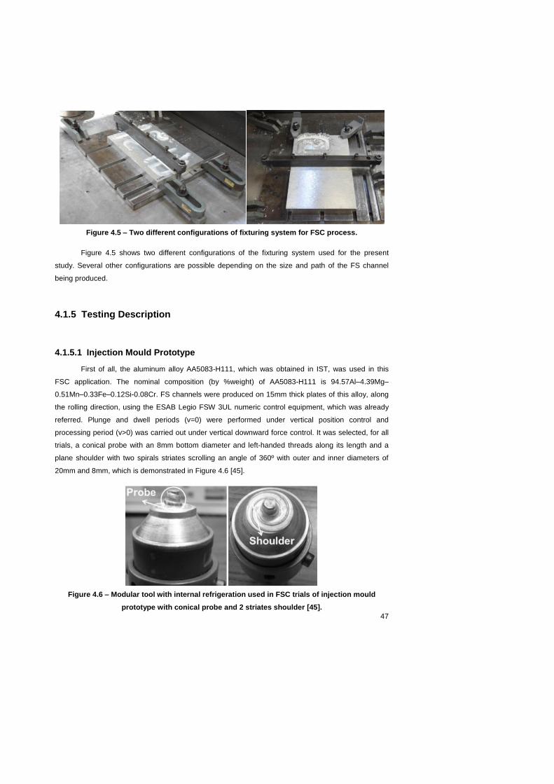
47
Figure 4.5 – Two different configurations of fixturing system for FSC process.
Figure 4.5 shows two different configurations of the fixturing system used for the present
study. Several other configurations are possible depending on the size and path of the FS channel
being produced.
4.1.5 Testing Description
4.1.5.1 Injection Mould Prototype
First of all, the aluminum alloy AA5083-H111, which was obtained in IST, was used in this
FSC application. The nominal composition (by %weight) of AA5083-H111 is 94.57Al–4.39Mg–
0.51Mn–0.33Fe–0.12Si-0.08Cr. FS channels were produced on 15mm thick plates of this alloy, along
the rolling direction, using the ESAB Legio FSW 3UL numeric control equipment, which was already
referred. Plunge and dwell periods (v=0) were performed under vertical position control and
processing period (v>0) was carried out under vertical downward force control. It was selected, for all
trials, a conical probe with an 8mm bottom diameter and left-handed threads along its length and a
plane shoulder with two spirals striates scrolling an angle of 360º with outer and inner diameters of
20mm and 8mm, which is demonstrated in Figure 4.6 [45].
Figure 4.6 – Modular tool with internal refrigeration used in FSC trials of injection mould
prototype with conical probe and 2 striates shoulder [45].

48
The FSC parameters implemented, while producing the injection mould prototype, are shown
in Table 4.5. All channels were produced with a very small gap between the shoulder and the
workpiece.
Table 4.5 – FSC process parameters for injection mould prototype.
Channel depth
Vertical force
Tool travel speed
Tool rotation speed
Rotation direction
Plunge speed
Dwell time
FSC control
8mm 420kg 100mm/min 400rpm CCW 0.1mm/s 5s Vertical force
control
4.1.5.2 Curing Process Mould Prototype
The material used to manufacture the curing process mould prototype was the aluminum alloy
AA5083-O, which was delivered to IST by Gleich Aluminum. FS channels were produced on 30mm
thick plates of this alloy, along the rolling direction. Plunge and dwell periods (v=0) were performed
under vertical position control and processing period (v>0) was carried out under vertical downward
force control with a 0º rake angle. It was selected, for all the runs, a cylindrical probe with an 8mm
bottom diameter and left-handed threads along its length and a plane shoulder with one spiral striate
scrolling an angle of 360º with outer and inner diameters of 19mm and 8mm, which is demonstrated in
Figure 4.7.
Figure 4.7 – Modular tool with internal refrigeration and with special insert for surface finishing
“add-in” used in FSC trials of curing process mould prototype with cylindrical probe and 1
striate shoulder.
The FSC parameters implemented, while producing the curing process mould prototype, are
shown in Table 4.6. All channels were produced with a very small gap between the shoulder and the
workpiece.
Table 4.6 – FSC process parameters for curing process mould prototype.
Channel depth
Vertical force
Torque Tool travel
speed
Tool rotation speed
Rotation direction
Plunge speed
Dwell time
FSC control
8mm 500kg 42N.m 100mm/min 600rpm CCW 0.1mm/s 8s Vertical
force control

49
4.2 Injection Mould Prototype
First of all, a brief introduction of the company that participated in a partnership with IST to
perform this injection mould prototype. Iberomoldes is one of the largest mould engineering and
product development companies in the world with about 800 employees. At present, they supply the
following three distinct areas that can be commercialized jointly or separately:
Engineering and product development (including prototyping, quick tools & control gauges)
Moulds for injection of thermoplastics and metallic alloys
Production of plastic components for the automobile sector, electronics sector, etc.;
A great part of the moulds produced by Iberomoldes are used to produce plastic products.
Injection moulding has been the most popular method for making plastic products due to its high
efficiency and manufacturability. The injection moulding process includes three significant stages:
filling and packing stage, cooling stage, and ejection stage. Among these stages, the cooling stage is
considered by many to be the most important one because it mainly affects the productivity and
moulding quality. Normally, 70%~80% of the moulding cycle is taken up by the cooling stage. An
appropriate cooling channel configuration can considerably reduce the cooling time and increase the
productivity of the injection moulding process. On the other hand, an efficient cooling system which
achieves a uniform temperature distribution can minimize the undesired defects that influence the
quality of moulded part such as hot spots, sink marks, differential shrinkage, thermal residual stress,
and warpage [46] [47].
Taking into consideration the relevance of the cooling times in injection moulding, the task
suggested by Iberomoldes seemed very interesting. The challenging task to develop a prototype for
Iberomoldes, would clearly demonstrate the potential of FSC in producing a more effective cooling
channel configuration. The prototype was discussed with the company, to determine if it could be an
alternative to produce small dimension channels for moulds that produce thermoplastic parts by
injection moulding. The thermoplastic is heated up and injected in the mould filling up the cavities of
the mould that make up the part geometry, and then it is cooled down until the thermoplastic turns into
solid phase. The cooling part of the process is performed with the help of the mould cooling channels
that have water at room temperature passing through it. However, these moulds are supposed to have
cooling channels behind the moulding surface at an equivalent distance along all of the part geometry.
Owing to the complex geometries of certain parts, it is very challenging and sometimes impossible to
manufacture channels that are all of them at exactly the same distance from the moulding surface,
especially with conventional drilling techniques. FSC could be the solution for this challenge, because
it can manufacture these channels due to the flexibility of the FSC technology that permits the
channels to have any desired path with depth variations, as it was mentioned in the SWOT analysis in
the previous chapter.
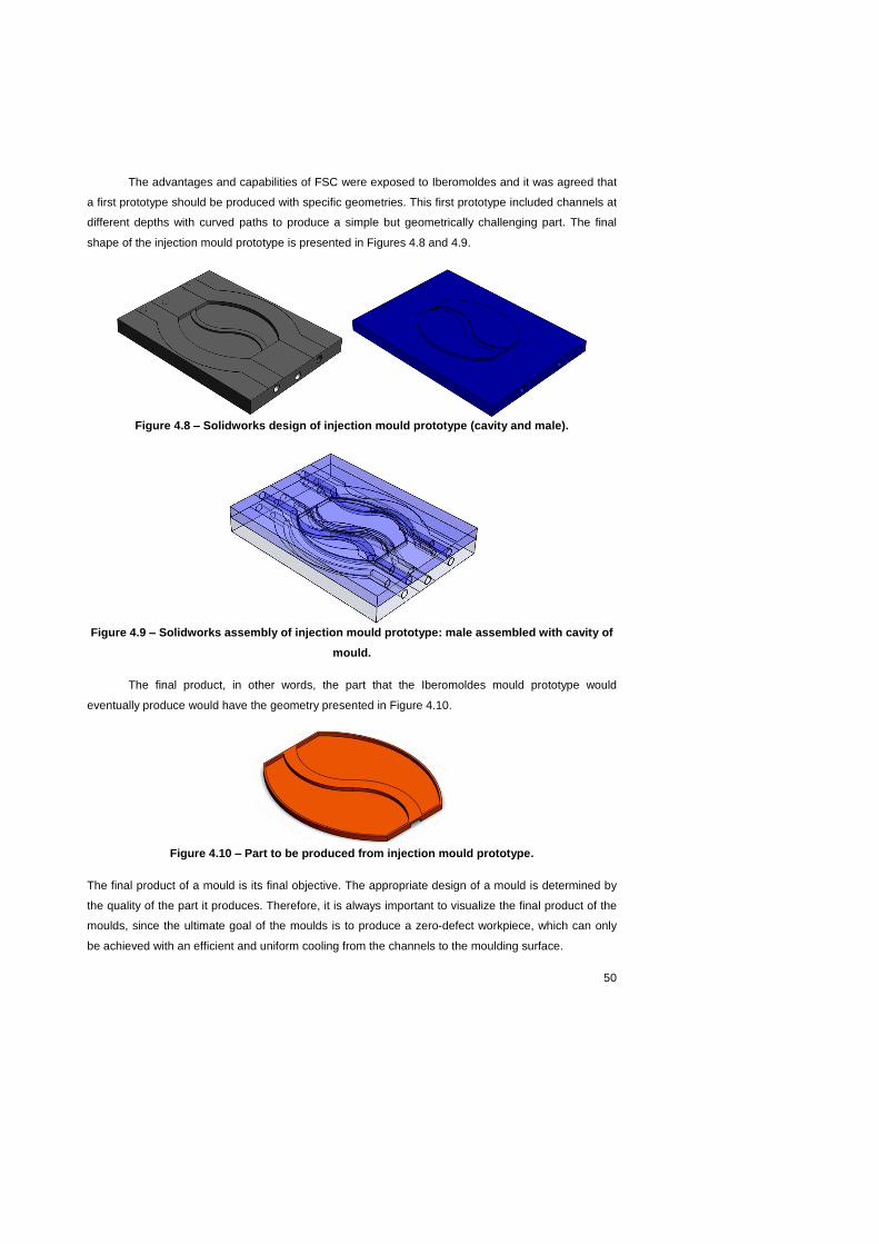
50
The advantages and capabilities of FSC were exposed to Iberomoldes and it was agreed that
a first prototype should be produced with specific geometries. This first prototype included channels at
different depths with curved paths to produce a simple but geometrically challenging part. The final
shape of the injection mould prototype is presented in Figures 4.8 and 4.9.
Figure 4.8 – Solidworks design of injection mould prototype (cavity and male).
Figure 4.9 – Solidworks assembly of injection mould prototype: male assembled with cavity of
mould.
The final product, in other words, the part that the Iberomoldes mould prototype would
eventually produce would have the geometry presented in Figure 4.10.
Figure 4.10 – Part to be produced from injection mould prototype.
The final product of a mould is its final objective. The appropriate design of a mould is determined by
the quality of the part it produces. Therefore, it is always important to visualize the final product of the
moulds, since the ultimate goal of the moulds is to produce a zero-defect workpiece, which can only
be achieved with an efficient and uniform cooling from the channels to the moulding surface.

51
4.2.1 Formulation of Objectives
The objective of this FSC application with Iberomoldes is to analyze if the manufacturing of FS
channels is feasible to function as conformal cooling channels of injection moulds that produce parts
with complex geometries. A secondary, and inherent, objective is to demonstrate the flexibility of the
FS channels, showing how the channels can have any path that is necessary even the most
complicated ones and at any desirable depth. The compromise of these two scenarios is the goal of
this FSC application, demonstrating that the FS channels can cool down a complex shaped part and
simultaneously illustrate the potential of FSC to manufacture channels with any desirable path.
In the case of injection moulding, the channels not only need to be close to the moulding
surface but they also need to be considerably short in length. Owing to the fact that, the moulds are at
high temperatures because injection moulding is a production process with very short cycle times, so
the mould is constantly at high temperatures. Therefore, when the cooling fluid enters the mould, it
starts heating up very rapidly and if it stays inside the mould channels too long, it reaches the mould
temperature and loses its cooling effect. As a result, if the conformal cooling channels are too long the
cooling fluid loses its low temperature along the channels. Consequently, the mould channels need to
be close to the moulding surface but bearing in mind that they need to have limited length. This
change in the cooling fluid temperature needs to be taken into consideration when designing moulds
for injection moulding.
A second important aspect to take in consideration in the design phase of an injection mould is
that mould channels need to have their inlets and outlets on the lateral walls of the mould plates. The
channel “racords” of the mould channels lie on the sidewalls of the moulds to connect to the cooling
fluid circuit of the injection mould. The liquids normally used in cooling fluid circuits of the moulding
industry are water or oil. The difference between the cooling fluid temperature and the mould
temperature is considerable and it decreases as the cooling fluid passes through the mould, therefore
it needs to go back to the cooling fluid circuit to reduce its temperature once again, therefore the only
possible surface to enable the continuous circulation in the cooling fluid circuit, are the lateral walls of
the mould cavity and male.
The proper process to develop a solid prototype is to execute computational simulations to
develop a suitable solution. Subsequently, the technological implementation is performed with its
inherent obstacles and limitations that always occur with innovative technologies. A detailed
description of the design development and corresponding problems encountered was provided, as
well as the processes involved in overcoming those same problems. Finally, a result analysis was
elaborated to consolidate the final comments on the injection mould prototype, including the learned
lessons for future development of FSC technology.

52
4.2.2 Computational Development of Solution
The computational development of the adequate solution for the injection mould prototype was
performed in Solidworks software. A flow analysis was then performed in Solidworks Floxpress, by
performing a cooling fluid flow analysis to the Solidworks design of the injection mould prototype. The
analysis was made assuming an internal flow of a specific cooling fluid within the mould channels,
which would heat up considerably the cooling fluid. The cooling fluid used in this case was water,
which is used in many injection moulding processes. This analysis demonstrates the effect of the
mould temperature on the cooling fluid and how the channels need to have a limited length, if not they
lose their functionality and will not cool down the part. Some different channel configurations were
analyzed and an optimal configuration was obtained for Iberomoldes to analyze at a later stage. An
important aspect that was considered, while developing different channel configurations was that the
part being produced needs to be uniformly cooled down so the channels need to be at an equivalent
distance from the moulding surface, in this case the mould cavity and male. It is important to
acknowledge that the mould cavity has to be cooled down at a uniform temperature throughout the
whole cavity to assure that the part has a first-class surface quality; the same scenario is applied to
the mould male.
Figure 4.11 – Simulation of cooling fluid flowing through the injection mould prototype with
fluid progressing along one of the FS channels.
The temperature conditions to approximate the computational development to reality were
defined as 50ºC at the channel inlet and 80ºC at the outlet of the FS channel. It is clear in Figure 4.11
that the cooling fluid velocity increases in the more curved parts of the channel paths, consequently
increasing the temperature of the cooling fluid. This property of the cooling fluid should be taken into
consideration when designing the conformal cooling channels.

53
Figure 4.12 – Cross section view of the injection mould prototype with the part placed on top of
the cavity mould, this procedure was performed in Solidworks software.
Another important aspect taken in consideration in this injection mould prototype was the inlet
and outlet of each channel. In the injection moulding industry, cooling channels connect to the cooling
fluid circuit through the lateral walls of the mould cavity and male. Consequently, the FS channels
need to begin and end on the lateral walls (sidewalls) of the mould prototype and it was a design
limitation considered in the technological implementation of the Iberomoldes mould prototype. Figure
4.13 shows the inlets of the FS channels with small cylinders inserted in the corresponding inlets.
Figure 4.13 – Simulation of different velocities of cooling fluid flowing through one FS channel
of the injection mould prototype.
The computational development of the adequate solution for a prototype should predict and
alert the researcher on possible obstacles that will appear during the technological implementation.
The computational development also assures that the design of the FS channels is feasible according
to the known technological limitations of FSC.
4.2.3 Technological Implementation
The technological implementation consisted in producing a injection mould prototype for
Iberomoldes to demonstrate that FSC is capable of producing conformal cooling channels for the
mould industry, and in this case more specifically for injection moulds. It is relevant to take into
consideration that when it comes to state of art technology, the technological implementation is by far
the most challenging stage. The process of developing a technology, especially such at an initial
stage, which is the case of FSC, involves constantly facing new obstacles, one after the other.
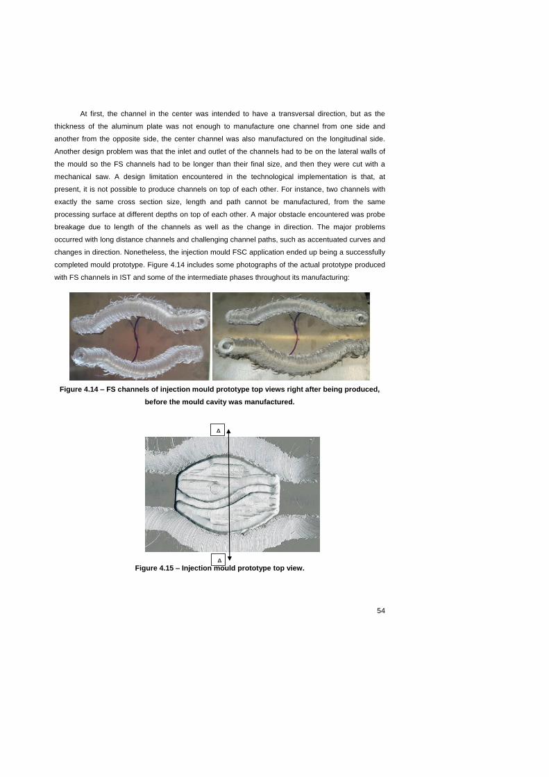
54
At first, the channel in the center was intended to have a transversal direction, but as the
thickness of the aluminum plate was not enough to manufacture one channel from one side and
another from the opposite side, the center channel was also manufactured on the longitudinal side.
Another design problem was that the inlet and outlet of the channels had to be on the lateral walls of
the mould so the FS channels had to be longer than their final size, and then they were cut with a
mechanical saw. A design limitation encountered in the technological implementation is that, at
present, it is not possible to produce channels on top of each other. For instance, two channels with
exactly the same cross section size, length and path cannot be manufactured, from the same
processing surface at different depths on top of each other. A major obstacle encountered was probe
breakage due to length of the channels as well as the change in direction. The major problems
occurred with long distance channels and challenging channel paths, such as accentuated curves and
changes in direction. Nonetheless, the injection mould FSC application ended up being a successfully
completed mould prototype. Figure 4.14 includes some photographs of the actual prototype produced
with FS channels in IST and some of the intermediate phases throughout its manufacturing:
Figure 4.14 – FS channels of injection mould prototype top views right after being produced,
before the mould cavity was manufactured.
Figure 4.15 – Injection mould prototype top view.
A
A

55
Figure 4.16 – Injection mould prototype cross section view.
Figures 4.14, 4.15 and 4.16 show the evolution of the injection mould prototype production.
First, the two outer channels were produced on one side of the 15mm thick aluminum plate. Then the
center FS channel was manufactured. Figure 4.16 clearly demonstrates that the channel bottom
surface of the centre channel is different from the other two. In Figure 4.17 it is possible to visualize
the final injection mould prototype produced with FS channels, including at the left a compact solid
cavity mould and at the right a sectioned mould cavity showing the FS channels cross sections.
Figure 4.17 – Perspective view of injection mould prototype with corresponding FS channels as
well as 4 sections demonstrating the FS channel cross sections.
The injection mould prototype was a success due to the fact that it demonstrated in a very
simple way how FSC can manufacture conformal cooling channels for a complex shaped part. After
trying some different channel configurations, a most advantageous channel configuration was
reached. To determine the best channel configuration two aspects were considered: channel length
and channel path. The channel path is related to the uniform cooling of the part, which is reflected on
the surface quality of the final produced part. The channel length is related to the high temperature of
the mould when producing at a very fast rate, so the FS channels cannot be very long for the cooling
fluid not to lose its cooling purpose.
A A

56
4.2.4 Result Analysis
The results of this first Case Study were very encouraging. The three FS channels of the
injection mould prototype were manufactured in one single step without any probe breakage or any
kind of major upset. However, these three successful runs were only attained after meticulous
investigation of the correct process parameters to use with that specific FSC tool and base material as
well as channel depth, channel length and channel path. All of these channel characteristics have to
be taken into consideration when defining the adequate process parameters. For each specific
channel the process parameters vary slightly and that know-how has to be obtained through a
painstaking process of trial and error. The technological implementation in an innovative process, such
as FSC, is the most relevant part of its development since it will determine all of the potential FSC
technology has.
The injection mould prototype development and implementation showed some major
difficulties that the evolution of FSC technology will face. The results demonstrate that the FSC
technology is still at a very initial stage and that it needs a lot of development and follow up. The range
of tool materials available for FSC technology is still limited. Various problems such as: FSC tool heat
up, poor channel geometry in long, curved and sharp curved channel paths, base material sticking to
the FSC tool, restricted usage of different base materials. All of these obstacles were encountered
throughout the production of the injection mould prototype.
Future developments will be focused towards solving these initial difficulties, which are
perfectly normal to occur with a technology that was recently discovered. FSC is an innovative solid-
state manufacturing technology that still has a long way to go, although it certainly is on the right track.
A future suggestion to improve the potential of FSC, which was suggested and reinforced by
Iberomoldes, is to develop a FSC tool that enables a FS channel to vary its depth (distance between
processed surface and channel base) along its path on other words, while the channel is being
produced. Consequently, FS channels would vary their depths according to the depth variation of the
moulding surface, giving FSC even more flexibility by allowing it to perform an internal channel with
any desirable path at a three dimensional scale.
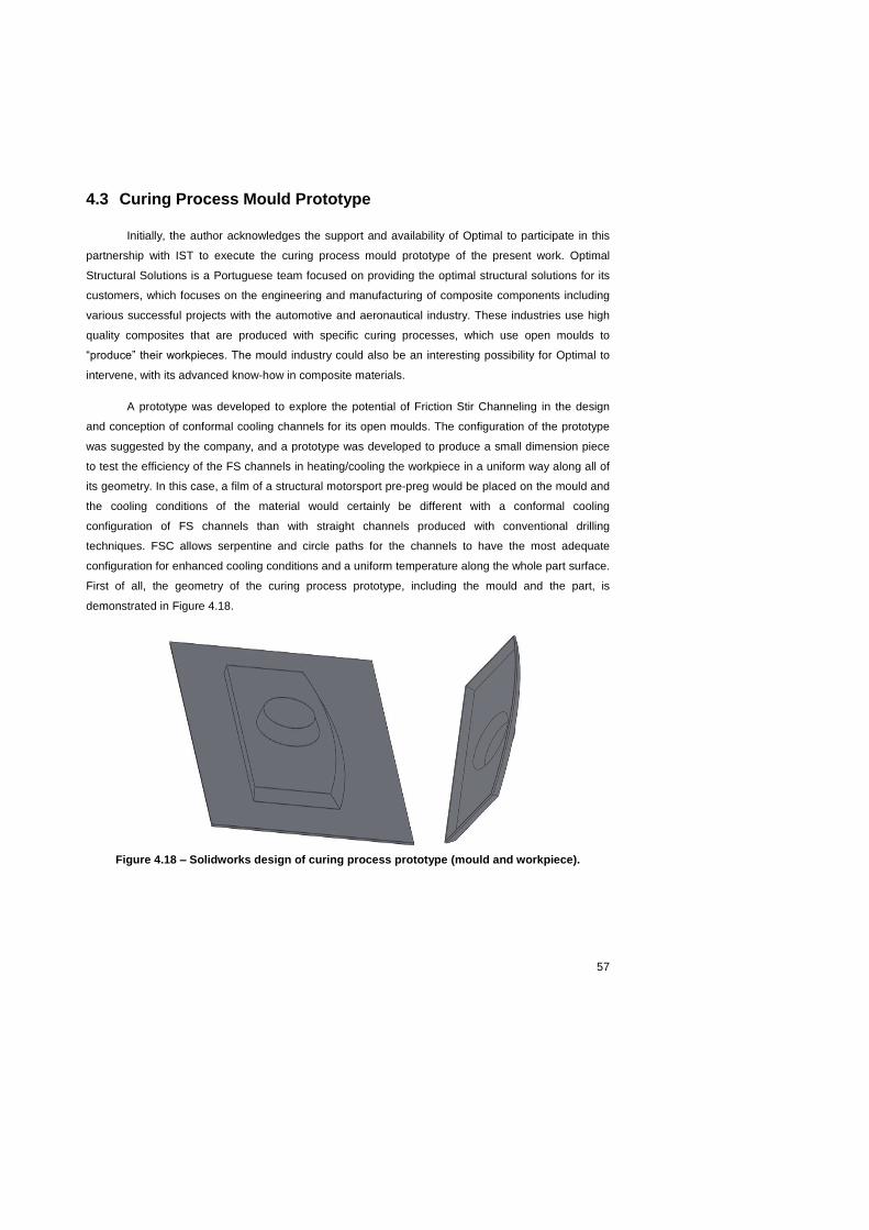
57
4.3 Curing Process Mould Prototype
Initially, the author acknowledges the support and availability of Optimal to participate in this
partnership with IST to execute the curing process mould prototype of the present work. Optimal
Structural Solutions is a Portuguese team focused on providing the optimal structural solutions for its
customers, which focuses on the engineering and manufacturing of composite components including
various successful projects with the automotive and aeronautical industry. These industries use high
quality composites that are produced with specific curing processes, which use open moulds to
“produce” their workpieces. The mould industry could also be an interesting possibility for Optimal to
intervene, with its advanced know-how in composite materials.
A prototype was developed to explore the potential of Friction Stir Channeling in the design
and conception of conformal cooling channels for its open moulds. The configuration of the prototype
was suggested by the company, and a prototype was developed to produce a small dimension piece
to test the efficiency of the FS channels in heating/cooling the workpiece in a uniform way along all of
its geometry. In this case, a film of a structural motorsport pre-preg would be placed on the mould and
the cooling conditions of the material would certainly be different with a conformal cooling
configuration of FS channels than with straight channels produced with conventional drilling
techniques. FSC allows serpentine and circle paths for the channels to have the most adequate
configuration for enhanced cooling conditions and a uniform temperature along the whole part surface.
First of all, the geometry of the curing process prototype, including the mould and the part, is
demonstrated in Figure 4.18.
Figure 4.18 – Solidworks design of curing process prototype (mould and workpiece).
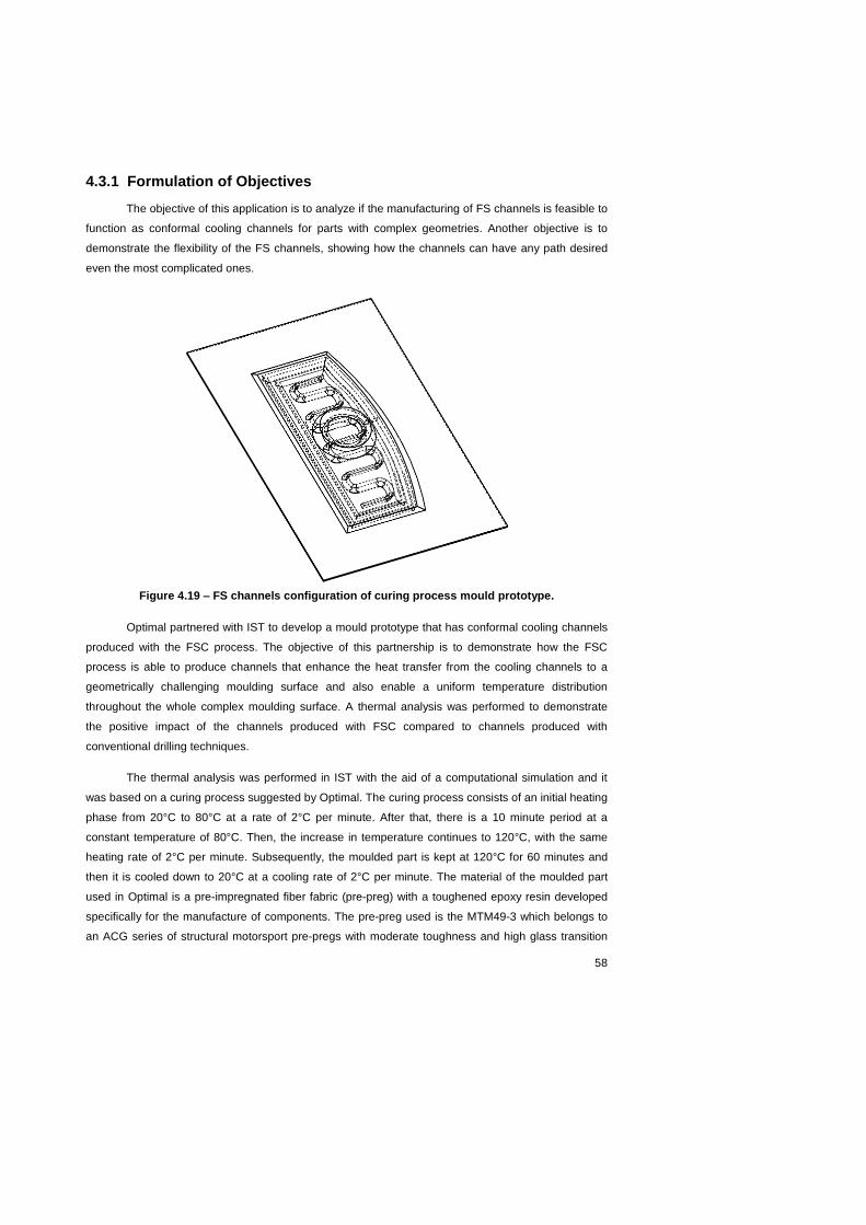
58
4.3.1 Formulation of Objectives
The objective of this application is to analyze if the manufacturing of FS channels is feasible to
function as conformal cooling channels for parts with complex geometries. Another objective is to
demonstrate the flexibility of the FS channels, showing how the channels can have any path desired
even the most complicated ones.
Figure 4.19 – FS channels configuration of curing process mould prototype.
Optimal partnered with IST to develop a mould prototype that has conformal cooling channels
produced with the FSC process. The objective of this partnership is to demonstrate how the FSC
process is able to produce channels that enhance the heat transfer from the cooling channels to a
geometrically challenging moulding surface and also enable a uniform temperature distribution
throughout the whole complex moulding surface. A thermal analysis was performed to demonstrate
the positive impact of the channels produced with FSC compared to channels produced with
conventional drilling techniques.
The thermal analysis was performed in IST with the aid of a computational simulation and it
was based on a curing process suggested by Optimal. The curing process consists of an initial heating
phase from 20°C to 80°C at a rate of 2°C per minute. After that, there is a 10 minute period at a
constant temperature of 80°C. Then, the increase in temperature continues to 120°C, with the same
heating rate of 2°C per minute. Subsequently, the moulded part is kept at 120°C for 60 minutes and
then it is cooled down to 20°C at a cooling rate of 2°C per minute. The material of the moulded part
used in Optimal is a pre-impregnated fiber fabric (pre-preg) with a toughened epoxy resin developed
specifically for the manufacture of components. The pre-preg used is the MTM49-3 which belongs to
an ACG series of structural motorsport pre-pregs with moderate toughness and high glass transition

59
temperature (Tg). One of the main features of these pre-pregs is that it has a wide range of end use
temperatures, which depend on the application of post-cure methods. They also have versatile
processing techniques, which include autoclave, vacuum bag or press moulding. Other than that, they
have a good tack and drape as well as a good impact resistance. The specific pre-preg used in this
thermal analysis (MTM49-3) has 42% resin content with a 2 by 2 Twill fabric of T800 carbon fiber [48].
The pre-preg specifications were provided by Optimal to approximate the thermal analysis as much as
possible to reality conditions.
The objective of this analysis is to show that a channel configuration that is closer to the actual
surface of the part being moulded is more efficient than a typical channel configuration produced by
conventional drilling techniques. FSC is an economic way to produce these channels with conformal
cooling properties, which can improve significantly the heat transfer between the heating/cooling
channels and meet the challenging complexities of certain moulding surfaces. The geometry of the
mould and corresponding moulding surface was developed by Optimal and suggested to IST. The
dimensions and geometries of the curing process mould prototype and the corresponding workpiece
(part) are presented in Figure 4.20.
Figure 4.20 – 3D dimensions of curing process mould prototype and corresponding workpiece.

60
Figure 4.21 – 2D dimensions of curing process mould prototype and corresponding workpiece.
Consequently, IST determined the most adequate channel configuration and produced a small
dimension prototype of the mould. Thereafter, Optimal produced the corresponding part to prove the
capability of the FSC process to produce complex shaped parts such as the one proposed by Optimal.
A thermal analysis seemed to be an adequate solution to investigate and prove the
capabilities of the FSC process in creating conformal cooling channels. To enable a clear
understanding of the heat transfer between the channels and the moulding surface, the thermal
analysis was performed in various stages. First of all, a simple block with a channel going through it
was modeled and analyzed to obtain a perception of all the boundary conditions needed and
simulation procedures to approximate it as much as possible to reality. After that, the contact
simulation was optimized with the introduction of a third layer, between mould and part, to
approximate the computational simulation to real conditions. The following stage was to define the
different channel configurations that would be used in the thermal analysis. Two conventional
configurations with straight path channels were included, to demonstrate the great difference in the
cooling uniformity compared to a channel configuration with conformal cooling FS channels.
Consequently, the major difference between heat transfer, from channels to moulding surface,
between FS channels and channels produced with conventional drilling techniques shows the great
potential FSC has for a successful introduction in various industries, more specifically in the mould
industry. FSC is a very low cost technology compared to other technologies that produce conformal
cooling channels, such as rapid prototyping. FSC can have a reasonable productivity with the
appropriate tools as well as a considerable flexibility. It is possible to have variation in depth and
channel size along a channel, just with simple evolutions in the present day FSC tools. FSC can,
without a doubt, in some years of thorough investigation and sustainable development, be a serious
and established manufacturing process of conformal cooling channels in the mould industry.

61
4.3.2 Computational Development of Solution
The computational analysis was performed in Abaqus, by performing a thermal analysis to the
Solidworks part of the curing process prototype (mould, interface and workpiece). The analysis was
executed assuming an internal flow of a specific cooling fluid, so the simulation was simplified to the
implementation of a constant temperature being transmitted from the fluid in the channels to the part
surface of the prototype. The value assumed for the temperature of the cooling fluid was assumed to
have the values of the temperatures provided by Optimal that were part of their curing process. Taking
into consideration that the part has to have a good surface quality, it is essential that the part surface
has to be heated up and cooled down at a uniform temperature throughout its entire surface.
The thermal analysis performed for Optimal was done in various steps. First, it was simplified
to the simplest form: a small block (rectangular prism) with a small channel across it. The heat transfer
from the channel to the top surface of the small block was analyzed. Then a thin film with all of the
epoxy resin properties (mechanical and thermal) was placed on the top surface of the block to
simulate the heat absorption of the resin, heat transfer and liberation to the air in natural convection
conditions. However the contact simulation was very poor. So, an extremely thin layer of a material
with a very low thermal conductivity, low density and low specific heat capacity was positioned
between the block and the epoxy resin. After determining the contact conditions and boundary
conditions, the channel configuration was determined. The two configurations produced with
conventional drilling techniques were produced only with straight path channels in the transversal for
one configuration and in the longitudinal direction for the other configuration. Both configurations had
several parallel channels along the limits of the moulding surface, and all at the same depths, with no
intersections to correspond to the manufacturing limitations of the conventional drilling techniques.
The conformal cooling configuration was produced with channels that have different paths and at
different depths with any desirable intersections, enabling channels very close to the moulding surface
and all of them at an equivalent distance from the moulding surface to accomplish a uniform
temperature distribution along all of the workpiece geometry. These different configurations were
produced in Solidworks and then imported into Abaqus.
The thermal analysis was initiated with a small block (rectangular prism) with only one channel
across its longer side and crossing it at middle height, in other words, starting and finishing in the
middle of one of the smaller faces. This first stage was performed to understand the different
behaviors of the heat transfer in Abaqus. Initially the idea was to analyze the heat transfer from the
channel to the top surface of the block just to verify if the properties were consistent with the flow of
heat transfer. As well as, to understand which would be the necessary boundary conditions to analyze
the desired heat transfer. Including, the geometry sections that should be considered as insulated and
others that should have boundary conditions with natural convection conditions with different
convection constants (h) depending on the different type of material. To have a clear view of this first
step of the thermal analysis, the block that was used in this first step is presented in Figure 4.22, in

62
which a specific high temperature was imposed in the channel as well as a constant heat flux on the
entire channel surface to acknowledge the heat transfer behavior:
Figure 4.22 – Block model developed in Abaqus software.
However a lot of limitations and lack of robustness was detected on the first stage of the
thermal analysis. Consequently, it was decided that a thin layer of material of about 2-3mm thick,
which was the thickness indicated by Optimal for the epoxy resin (pre-preg). This thin squared layer
was introduced in the thermal analysis to simulate the epoxy resin (pre-preg) used in Optimal and its
effect on the heat transfer, entering the pre-preg and exiting it, as well as the quantity of heat that it
absorbed. At this stage, the block was analyzed only with a thin rectangular portion of material with
epoxy resin (pre-preg) properties on top of it. The 2nd
version of this initial block simulation is
demonstrated in Figure 4.23.
Figure 4.23 – Block model with workpiece square unit on top.
The 2nd
version of the initial block model had a contact simulation that was not very realistic
and to obtain an accurate simulation of the contact conditions, it would be necessary to determine
different values of thermal conductance depending on the amount of clearance present between the
two components (materials). It was a requirement of the Abaqus software, so a more simplified
version was elaborated. A simpler solution for this specific problem was determined and a very thin
film of a material which represented the interface between the pre-preg and the block was added to
the simulation. The interface had specific properties, such as, extremely low values of density and
thermal conductivity, as well as a reduced value for the specific heat capacity. These properties
simulated the behavior of the small spaces that in real conditions always exist between two materials

63
that are in contact. Especially, in this case that we are dealing with an open mould, so the pre-preg
does not have pressure being applied to it against the mould. Consequently, the 3rd
version of the
initial block simulation is presented in Figure 4.24.
Figure 4.24 – Block model with interface between block and workpiece square unit.
Finally, a thermal analysis was performed to this initial block. It was heated up to 80°C,
imposing a constant temperature of 80°C to the channel surface area. This condition assumes that the
liquid passing through the channel is always circulating and an average temperature of 80°C is being
transferred to the channel walls, and then through conduction it transfers along the block and to the
interface and eventually to the prepreg squared layer. Clearly, with visual aid it is easier to
comprehend the heat transfer from the channel to its adjacent surfaces and the differences of heat
transfer through the diverging materials. This initial thermal analysis, heating up to 80°C, is the first
step of the curing process suggested by Optimal and encouraging results were obtained. The model
was improved through an iterative process of trial and error, which aided in defining the appropriate
properties of the interface component as well as some of the unkown properties of the prepreg. The
temperature distribution of this simplified thermal analysis, simple block and channel, is shown in
Figure 4.25, with the corresponding temperature values of the different colors (in degrees Celsius).
Figure 4.25 – Temperature distribution of block model heated up to 80°C (perspective).

64
In this intial analysis, the bottom surface of the block and its side walls were all with insulated
conditions, or in Abaqus software, when no boundary conditions are applied, it considers as an
insulated frontier. The contact definitions between block, interface and workpiece squared layer were
identical considering 50% of heat trasnfer (conductivity and convection) and radiation emission
between touching surfaces. Another boundary condition is the top surface of the workpiece squared
layer, which has a natural convection condition with a fluid temperature outside the thermal layer of
20°C and natural convection constant of 5 W/mK. In Figure 4.26, is a more frontal perspective of the
initial block of the thermal analysis, which clearly shows that it is possible to obtain a uniform
temperature distribution of the epoxy resin if the the channel configuration is appropriate according to
the complexity of the part geometry. Once again this perspective emphaizes that the channel
configuration should be given major importance. Defining the correct channel configuration can be the
most critical part of creating a mould with FS channels to have a succesful implementation of the FSC
process.
Figure 4.26 – Temperature distribution of block model heated up to 80°C (front view).
After defining the boundary conditions and understanding the heat transfer complexity, the
next step was to apply the appropriate geometries of the mould, interface and workpiece in the
thermal analysis. However, before that, it was imperative to define the adequate channel
configurations of the three moulds that were going to be analyzed, two with channels produced by
conventional drilling techniques and one with FS channels. After investigating some options, three
final versions were accomplished. The final channel configurations of the three moulds (3 Case
Studies) are demonstrated in Figure 4.27.
Case Study 1 – Case Study 2 – Case Study 3
Figure 4.27 – Channel configurations of all 3 Case Studies.

65
The channel configurations were designed and finalized with the Solidworks software. The first two
Case Studies have channels with straight paths because channels produced with drilling techniques
can only have straight paths and cross sections that are circles. On the other hand, Case Study (CS) 3
has the cross section of the typical FS channels (inverted rhombus) and have paths that approximate
as much as possible the channels to the complex-shaped moulding surface, with the intent of assuring
that all of them are at an equivalent distance from it.
The process of determining the channel configuration that enhanced the FSC potential and was
viable to the purpose of the mould, in other words, optimizing the curing process heat transfer as well
as assuring uniform temperature along the workpiece geometry and designing a channel configuration
that is feasible to produce with FSC and economic in terms of time and different runs. Taking into
consideration that a curing process is not an injection moulding process, so the cooling process is not
a matter of seconds and the channels can be quite longer because the heating/cooling process occurs
during a long period of time, so the temperature has more time to stabilize along the whole channel.
Figure 4.28 presents FS channels configurations that were considered before attaining the final one:
Figure 4.28 – Different FS channels configurations for curing process mould prototype, tested
before using final FS channels configuration (Case Study 3).

66
Now that all of the ingredients needed: theory, boundary conditions, component geometries and
case studies, were already determined, the computational simulation could be implemented.
Obviously, this computational simulation was performed to simulate a curing process performed in
Optimal as mentioned before, so it was divided in 4 major steps:
1. STEP 1: Heating from 20°C to 80°C at a rate of 2°C/min during 30 minutes.
2. STEP 1A: Plateau at 80°C during 10 minutes.
3. STEP 2: Heating from 80°C to 120°C at a rate of 2°C/min during 20 minutes.
4. STEP 2A: Plateau at 120°C during 60 minutes.
These 4 steps were introduced in Abaqus and a mesh with a Heat Transfer element type, a tetahedral
element, was created with the same approximate global seed size for each component of 4 with a
curvature control maximum deviation factor of 0.1 and minimum size factor, as fraction of global seed
size of 0.1. Owing to the fact that, the components were imported from Solidworks, their shapes were
not defined in Abaqus, so the only possible element type in the “Heat Transfer” family is the tetahedral
(tet) type, the DC3D4: a 4-node linear heat transfer tetrahedron. This situation occurred due to
irregularities in the component geometries especially due to the complex-shaped moulding surface
and FS channels. The author determined that the step periods correspond to a time period of 1
minute: Therefore, STEP 1 has a time period of 30, STEP 1A has a time period of 10, STEP 2 has a
time period of 20 and STEP 2A has a time period of 60. The boundary conditions of the thermal
analysis were the 20°C to all components at the intial stage before STEP 1. The workpiece had a
natural convection with a constant of 5 W/mK and a surrounding temperature of 20°C and the mould
with a natural convection constant of 20 W/mK and the same surrounding temperature. The boundary
conditions applied in each step only considered the corresponding temperatures applied on the
channel surface areas. The contact simulation applied to the contacts between mould and interface as
well as interface and workpiece, were both considered to transfer 50%of the total heat transfer and
50% of the total emissivity.
These basic conditions were maintained for all three Case Studies. It is important to mention
that the cooling down part of the curing process was excluded from the computational simulation
because it was thought to be of minor importance. The focus of this thermal analysis was to assure
that the heat transfer of the FS channels to the moulding surface was more efficient than that of the
other channels. So, the critical part of the curing process for this thermal analysis was to determine if
the workpiece was uniformily heated at the end of the last high temperature (120°C) plateau. The
ultimate goal of this thermal analysis is assuring that the final surface quality of the workpiece is the
best possible. Since the section of the curing process that majorly affects the workpiece surface
quality is the section with highest temperatures, it was defined that the cooling down phase of the
curing process could be removed from the computational simulation due to its lack of relevance for the
research being performed.

67
The graph, presented in Figure 4.29, with a Temperature vs. Time curve, demonstrates the
conditions of the curing process used in the computational simulation:
Figure 4.29 – Temperatures versus time of Optimal curing process.
The computational simulation had three main components, each one with its corresponding properties
and attributes. Figure 4.30 clearly demonstrates the three main components associated with the
computational simulation of the curing process, which the mould prototype will encounter:
Figure 4.30 – Properties distribution of curing process prototype computational simulation.
Obviously, these three main components have different properties and behaviours. So, in the
computational simulation these different properties have to be introduced to simulate their different
characteristics throughout the simulation and to approximate as much as possible to the real
conditions of the curing process. The properties of each component that are listed below were
obtained from various literatures, which are also referenced. The material used for the mould
component was the AA 2024-T6, due to lack of information on thermal properties of AA 5083, with a
nominal composition in weight percent of 4.5Cu–1.5Mg–0.6Mn. The properties of the interface were
determined by the author and in the case of the workpiece, some properties were given by Optimal
while others were determined by the author from intensive research in various literatures.
0
50
100
150
0 20 40 60 80 100 120 140
T [°
C]
t [minutes]
Optimal Curing Process

68
The mould component had the thermal and mechanical properties of the aluminum alloy, AA
2024-T6, presented in Figure 4.31, including their variations with temperature, which were considered
in the computational simulation [49]:
Figure 4.31 – Properties distributions and values for mould component [49].
Table 4.7 - Properties values for the interface (defined by the author) and the workpiece
component [48] [50].
Component Thermal
Conductivity Density
Thermal Natural Convection
Specific Heat
Interface 0.05 W/mK 100 kg/m3 - 200 J/kgK
Workpiece 0.5 W/mK 1220 kg/m3 0.5 W/m
2K at 20ºC 794 J/kgK
Identical computational simulations were performed to the three Case Studies and it was clear
that the Case Study (CS) 3 with the FS channels had a more enhanced heat transfer between the
channels and the moulding surface as well as a more uniform distribution of the temperature along the
workpiece. The images below demonstrate a clear difference between the moulds that have channels
with channels produced with conventional drilling techniques and channels produced with FSC.
Figures 4.32 and 4.33 show two different cross sections, one of the largest side of the mould and the
second one of the smallest side of the mould. The differences between CS 3 and the other two Case
Studies are obvious:

69
Figure 4.32 – Cross sections of the longitudinal (longer) side of the 3 components at the end of
the curing process prototype computational simulation with the corresponding temperature
distribution for all of the 3 Case Studies.
Figure 4.33 – Cross sections of the transversal (short) side of the 3 components at the end of
the curing process prototype computational simulation with the corresponding temperature
distribution for all of the 3 Case Studies (Case Study = CS).

70
The red circles in Figures 4.32 and 4.33 highlight the major differences between the first two
Case Studies and the FSC mould (Case Study 3). The FSC mould demonstrates the impact the
proximity of the heating/cooling channels to the moulding surface can have on the heat transfer to the
workpiece. The poor heat transfer to the workpiece in complex-shaped moulding surfaces is a major
issue of the moulding industry and FSC is the “perfect” solution for that same issue. Consequently, a
very important factor when designing a mould is to assure that the FS channels are as close as
possible to the moulding surface and all of them are at an equivalent distance to assure a uniform heat
transfer along all of the workpiece geometry. It is essential to note that, as in Case Study (CS) 3, when
the channels are not close enough to the moulding surface, they will not have the desired effect on the
heat transfer form heating/cooling channels to the moulding surface. A good example in the FSC
mould is on the inclinated faces of the moulding surface, the heat tansfer of CS 3 is better than the
other two but it could be much better if a channel was manufactured right below it. As a result, this
reality always has to be present when producing FS channels for moulds. The FSC feature that
differentiates it from conventional drilling techniques has to be exploited as much as possible, to
enhance the heat transfer between channels and moulding surface. Therefore, the FS channels
should be produced as close as possible to the moulding surface in any mould. A precise
measurement should be made to enable the channels to be equidistant from the moulding surface so
the heating/cooling of the workpiece is uniform along its geometry.
4.3.3 Technological Implementation
As in the injection mould FSC application, the technological implementation faced obstacles
inherent to a technology that is in the initial stage of its development. The process parameters have
been optimized as well as the FSC tool material and base material, but any time there is a slight
change in any of these variables, all of this process has to be redone. Nonetheless, using the material
provided by Optimal, the curing process mould prototype was produced in IST with success. Figure
4.34 shows top views of FS channels produced along the manufacturing of the prototype:
Figure 4.34 - FS channels of curing process mould prototype with serpentine and contour
paths (top views) immediately after being produced and before the moulding surface was
manufactured.

71
The prototype developed in this FSC application demonstrates once again the applicability of
FSC to the mould industry, and not only in the injection moulding industry (Figure 4.35). There are
many other processes that use moulds such as this prototype that undertake curing processes of fiber
carbon materials, which involve processes with bigger durations and slower variations in temperature
when compared to injection moulding cooling processes. The technological implementation of the
curing process mould prototype had three main challenges: the length of one FS channel, the
serpentine path of another FS channel and the depth for the third FS channel. All three challenges
were overcome, with a certainty that FSC process parameters need to be consolidated, so that slight
variations in the process parameters can be more controllable.
Figure 4.35 – Two FS channels of curing process mould prototype immediately after being
manufactured.
The discoveries made along the technological implementation of the curing process mould
prototype provided consistent evidence that FSC is a technology that has to be operated at “colder
conditions” than FSW and all of the other friction stir based technologies. This appreciation can be
proved with actual demonstrations of the FS channels cross sections, demonstrating a considerable
capacity of extracting material and at the same time to maintain the processed surface at the initial
level and with a considerable surface quality/roughness. Figure 4.36 demonstrates the processed
surface of two FS channels immediately after being manufactured with “colder conditions”. Apparently,
if these optimal process parameters are attained the processed surface is almost unaffected by the
FSC process. Once again, Figure 4.36 illustrates one more unique capability of FSC in comparison
with alternative technologies, which definitely increases its potential as an industrial application.
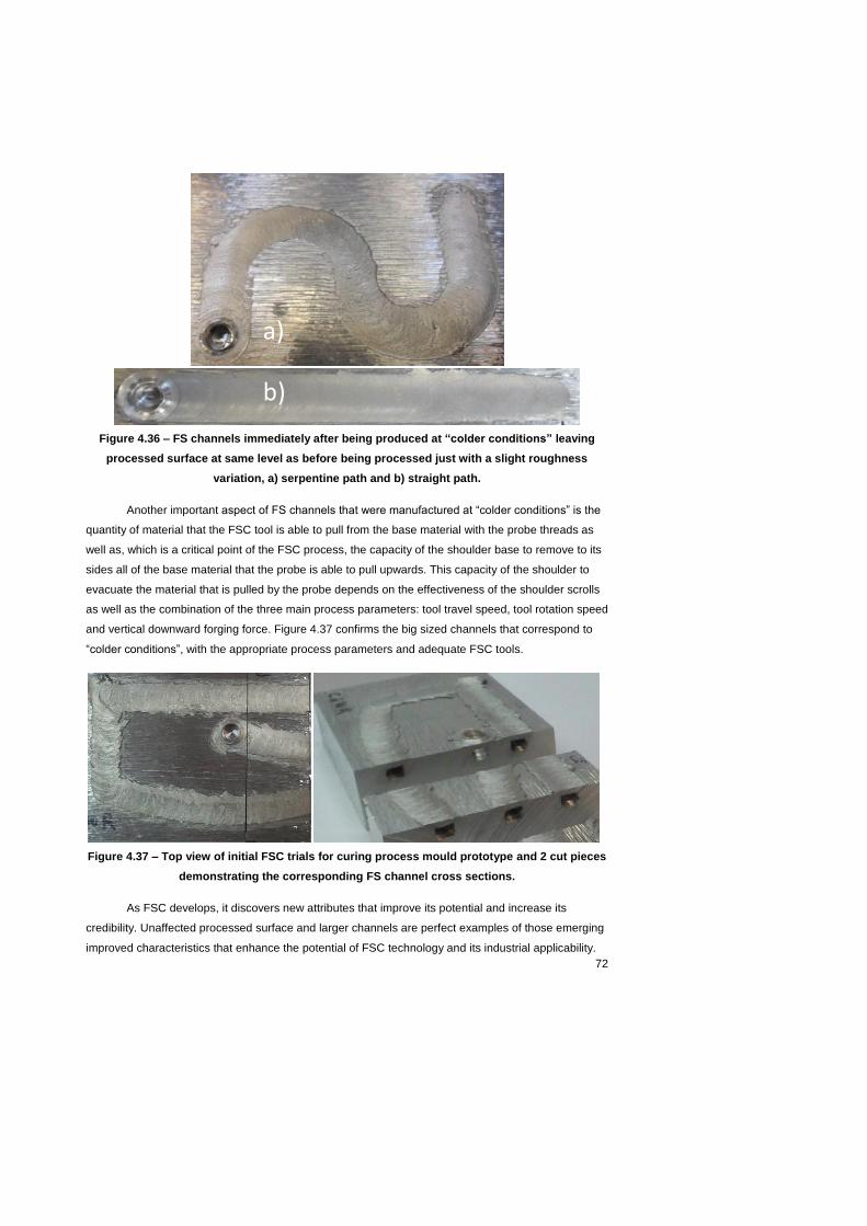
72
Figure 4.36 – FS channels immediately after being produced at “colder conditions” leaving
processed surface at same level as before being processed just with a slight roughness
variation, a) serpentine path and b) straight path.
Another important aspect of FS channels that were manufactured at “colder conditions” is the
quantity of material that the FSC tool is able to pull from the base material with the probe threads as
well as, which is a critical point of the FSC process, the capacity of the shoulder base to remove to its
sides all of the base material that the probe is able to pull upwards. This capacity of the shoulder to
evacuate the material that is pulled by the probe depends on the effectiveness of the shoulder scrolls
as well as the combination of the three main process parameters: tool travel speed, tool rotation speed
and vertical downward forging force. Figure 4.37 confirms the big sized channels that correspond to
“colder conditions”, with the appropriate process parameters and adequate FSC tools.
Figure 4.37 – Top view of initial FSC trials for curing process mould prototype and 2 cut pieces
demonstrating the corresponding FS channel cross sections.
As FSC develops, it discovers new attributes that improve its potential and increase its
credibility. Unaffected processed surface and larger channels are perfect examples of those emerging
improved characteristics that enhance the potential of FSC technology and its industrial applicability.
a)
b)

73
4.3.4 Result Analysis
FSC demonstrated in the present work that it can be a solution for complex shaped
workpieces due to the challenging conditions to maintain uniform temperature along all of the
moulding surface geometry. This situation is more evident in processes such as the Optimal curing
process, in which uniform temperature along the whole workpiece is the ultimate goal. In this case, the
thermal analysis performed in this study clearly showed the potential FSC has to maintain a uniform
temperature, while heating/cooling a complex shaped workpiece along all of its geometry.
The channel manufactured for this FSC application, a curing process mould prototype, with a
serpentine path along great part of the longitudinal side of the moulding surface indicates the
possibility of introducing FSC in the heat exchanger industry. Heat exchangers need channels with
identical paths in extremely reduced spaces. Therefore, a lot of investigation and hard work has to be
performed in IST to allow FSC to produce channels with smaller sizes, longer paths and with sharper
curves. The FS channel surface roughness also needs to be taken into consideration for the heat
exchanger industry due to the pressure and temperature drops. FSC technology still has this limitation
and a solution to control it needs to be discovered.
The results obtained show that the FSC technology is still at a very initial stage and it still
needs a lot of development and follow up. A major problem still to be solved in FSC technology is the
tool material. The major obstacle encountered while producing FS channels was probe breakage. The
FSC technology is not yet completely controlled, so the process parameters are not always adequate.
Even when, process parameters are adequate probe breakage can occur due to fatigue, which also
increases with the channel path complexity especially with change in channel direction. In the FSC
process, the tool material needs to be very resistant in terms of hardness as well as resistant to
flexion. Inherent related problem arise such as: tool heating, poor channel geometry in long, curved
and sharp curved channel paths. All of these obstacles were encountered in the development of FSC,
but with a continuous increase of know-how the corresponding solutions were rapidly discovered.
Nonetheless, encouraging results were obtained, assuring an enthusiastic future for the
evolution and consequent implementation of FSC in the mould industry and possibly in the heat
exchanger industry. However, a lot of investigation and technological development is still needed for
FSC to have a successful entrance in the “industries”. FSC has all of the necessary attributes to be a
competitive alternative to conformal cooling channel producers. The ease that FSC has to produce
channels with any path also enables it to be introduced in the heat exchanger industry, but that has
not been thoroughly investigated in this dissertation. On the other hand, it is important to acknowledge
that FSC is still at a very early stage of its maturity and it still needs a long way to grow and most of all
to gain robustness. The results show FSC has high potential and adequate features to develop into a
manufacturing technology of the mould industry and perhaps the heat exchanger industry.
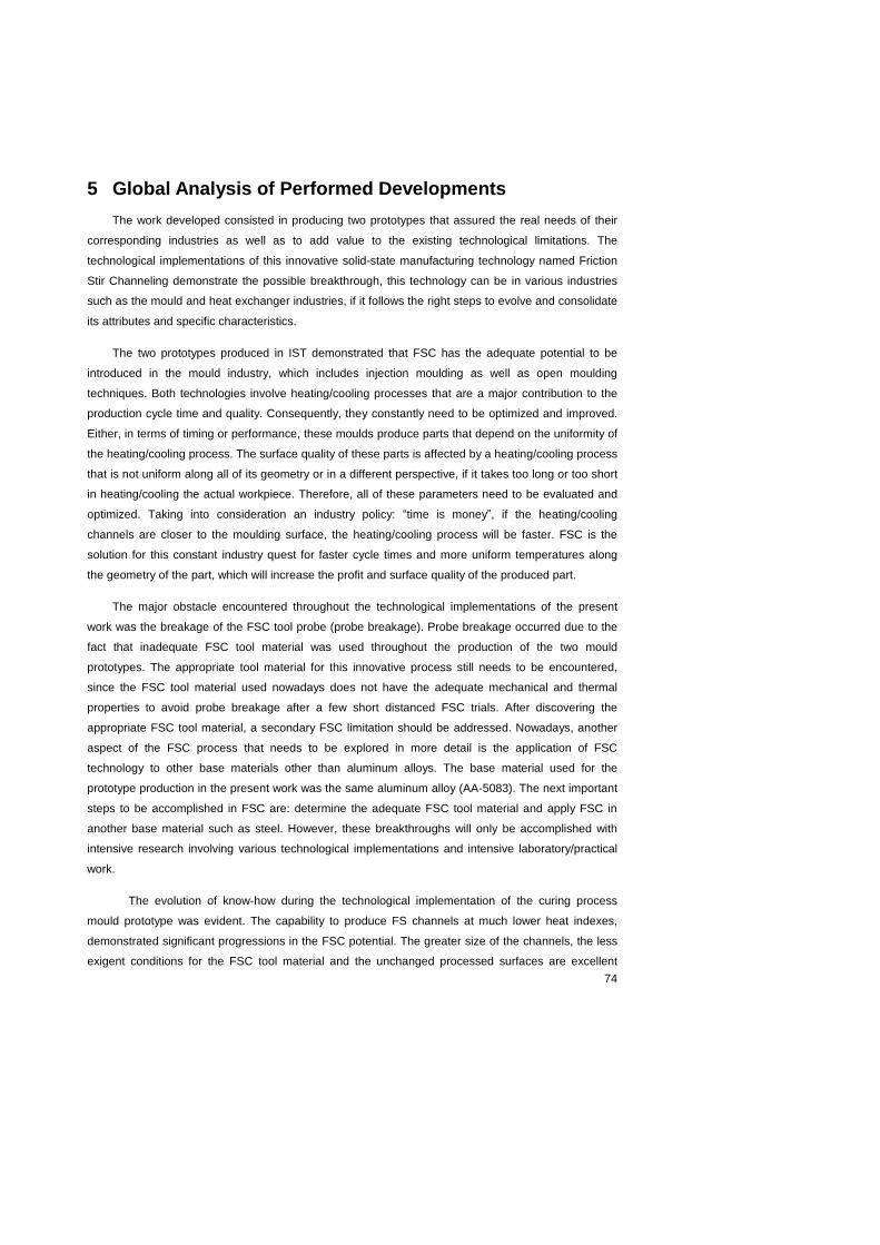
74
5 Global Analysis of Performed Developments
The work developed consisted in producing two prototypes that assured the real needs of their
corresponding industries as well as to add value to the existing technological limitations. The
technological implementations of this innovative solid-state manufacturing technology named Friction
Stir Channeling demonstrate the possible breakthrough, this technology can be in various industries
such as the mould and heat exchanger industries, if it follows the right steps to evolve and consolidate
its attributes and specific characteristics.
The two prototypes produced in IST demonstrated that FSC has the adequate potential to be
introduced in the mould industry, which includes injection moulding as well as open moulding
techniques. Both technologies involve heating/cooling processes that are a major contribution to the
production cycle time and quality. Consequently, they constantly need to be optimized and improved.
Either, in terms of timing or performance, these moulds produce parts that depend on the uniformity of
the heating/cooling process. The surface quality of these parts is affected by a heating/cooling process
that is not uniform along all of its geometry or in a different perspective, if it takes too long or too short
in heating/cooling the actual workpiece. Therefore, all of these parameters need to be evaluated and
optimized. Taking into consideration an industry policy: “time is money”, if the heating/cooling
channels are closer to the moulding surface, the heating/cooling process will be faster. FSC is the
solution for this constant industry quest for faster cycle times and more uniform temperatures along
the geometry of the part, which will increase the profit and surface quality of the produced part.
The major obstacle encountered throughout the technological implementations of the present
work was the breakage of the FSC tool probe (probe breakage). Probe breakage occurred due to the
fact that inadequate FSC tool material was used throughout the production of the two mould
prototypes. The appropriate tool material for this innovative process still needs to be encountered,
since the FSC tool material used nowadays does not have the adequate mechanical and thermal
properties to avoid probe breakage after a few short distanced FSC trials. After discovering the
appropriate FSC tool material, a secondary FSC limitation should be addressed. Nowadays, another
aspect of the FSC process that needs to be explored in more detail is the application of FSC
technology to other base materials other than aluminum alloys. The base material used for the
prototype production in the present work was the same aluminum alloy (AA-5083). The next important
steps to be accomplished in FSC are: determine the adequate FSC tool material and apply FSC in
another base material such as steel. However, these breakthroughs will only be accomplished with
intensive research involving various technological implementations and intensive laboratory/practical
work.
The evolution of know-how during the technological implementation of the curing process
mould prototype was evident. The capability to produce FS channels at much lower heat indexes,
demonstrated significant progressions in the FSC potential. The greater size of the channels, the less
exigent conditions for the FSC tool material and the unchanged processed surfaces are excellent

75
evidences of a great leap in the development of FSC technology. This leap completely changed the
concept of this innovative technology making it a technology closer to a plastic deformation process
than to a viscous flow of material. Consequently, the productivity and flexibility of FSC can increase
providing it with more strengths and opportunities compared to alternative technologies already
established in the industry.
Obviously, technologies that manufacture internal conformal cooling channels for moulds already
exist. However, FSC is able to produce those channels at a lower cost and at an industry standard
productivity. Taking into consideration that the industry is always searching for lower production costs
while maintaining the same productivity, FSC can be the appropriate solution the industry is looking
for. FSC can easily follow the steps of FSW and be the most important achievement in the ‘welding
world’ of the present decade. Nonetheless, it still needs countless investigations, endless hours and a
lot of money invested in its development. The industrial applications of FSC are evident and it can be
an alternative technology to the already existent ones due to its different characteristics that satisfy the
industry requirements. Especially, when it comes to complex shaped parts, FSC can be a
breakthrough technology to produce at an average rate with low production costs conformal cooling
channels with paths that are complicated to manufacture with some alternative technologies already
existing in the industry as well as very expensive with other ones.
A tough reality about the industry is that it always wants numbers, which establish and compare
the precise capabilities of all the different manufacturing technologies that are capable of helping it.
The numbers that define FSC are: the ranges of channel depth, the maximum channel length, the
minimum and maximum channel sizes, the specific channel geometry, the surface wettability of the
channels, the channel productivity rates in comparison with changes in its different characteristics as
well as the channel surface roughness. All of these numbers that specify the physical limitations of
FSC need to be determined, in order to provide the industry with proofs of its real potential.
76
6 Conclusions
The following overall conclusions result from the present study:
The results of the present work show that FSC is capable of producing internal channels with
any desirable path.
The SWOT analysis undertaken in the present work shows that FSC finds the compromise
between advantages and disadvantages of the alternative technologies and has potential to
offer solutions that no other technology in the industry provides.
The thermal analysis performed in the present work clearly showed the potential FSC has to
produce channels that maintain a uniform temperature while heating/cooling a complex
shaped workpiece along all of its geometry.
The two prototypes developed in the current work demonstrated that FSC has the adequate
potential to be introduced in the mould industry, which includes injection moulding as well as
open moulding techniques.
The results show that FSC can reduce cycle times and obtain more uniform temperatures
along the geometry of the part, increasing the profit as well as surface quality of the produced
part.
The higher productivity of FSC compared to alternative technologies is a major opportunity for
it to be implemented in various industries that depend on high productivity rates.
The rough surface finish of the processed part and of the internal channel are possible threats
to the FSC technology, but they can easily be suppressed by an evolution (which is being
developed) to improve surface finish of processed surface. On the other hand, the rough
internal channel surface finish can even aid in enhancing the heat transfer from the channels
to the moulding surfaces due to an increased wet surface (surface “wetted” by heating/cooling
fluid). Nonetheless, the pressure and temperature drops due to high surface roughness of FS
channels are still a limitation, and a possible threat, for FSC.
FSC has potential to “penetrate” the mould industry, to optimize heating/cooling times and
enhance uniform heating/cooling performance in complex shaped moulding surfaces, which
implies having a complex shaped workpiece (part).
FSC has the possibility due to its inherent process demands to operate at a very low cost,
which gives FSC a distinct aptitude in comparison with alternative conventional drilling
techniques that are present in many industries throughout the world.

77
The approach undertaken in the present work that consisted in designing a computational
solution based on which the experiments were performed, allowed to reach a good result in a
productive and cost effective way. Industrial applications will benefit from similar applications.
The technological implementation of the proposed computational solutions allowed to identify
a range of problems, typical of preliminary studies in any innovative manufacturing technology
and to pin point corresponding solutions.
The production of the two prototypes allowed to identify the high sensitivity of FSC to minimal
material and procedure alterations, namely compared to FSW. Thus, procedure development
needs to be accurate.
FSC could develop the potential to be a producer of channels (mini channels) for the heat
exchanger industry.
FSC still needs a lot of research and sustainable development to reach enough maturity, and
to eventually be introduced in its potential industries, being until now the mould and the heat
exchanger industry.
Some future work proposals would be:
A preliminary step would be to define an adequate material for probes, to avoid the current
high rate of probe breakage.
First of all, to consolidate FSC process parameters and possible FSC tool materials it is
essential to determine a certain range of process parameters and corresponding materials
that need to be thoroughly evaluated and tested.
Second, determine durability of probes and shoulders with different sizes and features.
Determine their ranges and corresponding channel lengths and sizes. Consolidate all of the
possible sets into a reference table that could be used as a base template for all FSC process
parameters.
Determine relations between all of the possible process parameters with different base
materials, as well as different materials for the FSC tool (probe and shoulder), with an inherent
goal of defining limits for material, depth, length and path ranges, which means minimums and
maximums for all of these parameters.
After determining all possible process parameters and materials that can be used, compare in
qualitative and quantitative terms with alternative technologies that were introduced in the
present study.
An immediate evolution in the FSC tool would be to increase by more or less 50% the size of
shoulder striates and to use shoulders with only one striate on each side of the probe and with

78
the surface finishing “add-in” developed by C. Vidal and P. Vilaça in IST, which can be
incorporated in any FSC tool.
At last, design and produce a FSC tool that permits variation in the z direction as it produces
internal conformal channels enabling variation of channel depth along its path, which can also
vary in any direction. This means an even greater flexibility in internal conformal channel
manufacturing.
Share FSC know-how with other researchers to boost the technological development of FSC,
such as Balasubramanian and Mishra, which were referred in the present work.
Explore the heat exchanger industry in terms of possible applications for FSC. FSC has the
capability, in the near future, to produce low cost heat exchangers at a considerable rate
owing to its capability of producing small dimension internal channels in flat or curved
surfaces, with any possible path. In this case, it is essential to take in consideration the
capability of FSC to produce internal channels with serpentine paths.
Investigate other possible industrial applications such as: (i) solar panels could be fabricated
with channels that join three thin plates by its thickness side forming channels and at the same
time welding them together; (ii) produce heating/cooling channels of heat pump systems with
serpentine paths as for the heat exchanger industry.

79
7 References
[1] T. M. Wayne, international patent n. PCT/GB92/02203 and patent GB n. 9125978.8,
December 6 1991.
[2] TWI – World Centre for Materials Joining Technology, Friction Stir Welding at TWI, available
in: <http://www.twi.co.uk/technologies/welding-coating-and-material-processing/friction-stir-
welding/>. Access in: July 2011.
[3] R.S. Mishra, Z.Y. Ma, “Friction stir welding and processing”, Materials Science and
Engineering R, 50, (2005), pp. 1-78.
[4] T. Gomes dos Santos. “Ensaios Não Destructivos por Correntes Induzidas: Desenvolvimento
e Aplicação à Soldadura por Fricção Linear”, PhD Thesis, IST, July 2009.
[5] C. Vidal, “Análise da Melhoria do Comportamento à Fadiga em Juntas Soldadas por Fricção
Linear de Ligas de Alumínio para a Indústria Aeronáutica”, MSc Thesis, IST, July 2009.
[6] R. S. Mishra. “Integral Channels in Metal Components and Fabrication Thereof”, U.S. Patent
6,923,362 B2, 2 August 2005.
[7] N. Balasubramanian, R.S. Mishra, K. Krishnamurthy, “Friction stir channeling:
Characterization of the channels”, Journal of Materials Processing Technology 209 (2009), pp.
3696–3704.
[8] P. Vilaça, C. Vidal, “Ferramenta Modular Ajustável e Respectivo Processo de Abertura de
Canais Internos Contínuos em Componentes Maciços (Modular adjustable tool and
correspondent process for opening continuous internal channels in solid components)”,
National patent pending N.º 105628 T, 15 April 2011.
[9] C. Vidal, V. Infante, P. Vilaça, “Mechanical Characterization of Friction Stir Channels under
Internal Pressure and In-Plane Bending”, Key Engineering Materials, Vols. 488-489 (2012),
pp. 105-108.
[10] N. Balasubramanian, R.S. Mishra, K. Krishnamurthy, “Process forces during friction stir
channeling in an aluminum alloy”, Journal of Materials Processing Technology 211 (2011), pp.
305-311.
[11] C. Vidal, V. Infante, P. Vilaça, “Metallographic Characterization of Friction Stir Channels”, VI
International Materials Symposium (MATERIAIS 2011), Guimarães, Portugal, 18-20 April,
2011.
[12] R.F. Hamade and F. Ismail, “A case for aggressive drilling of aluminum”, Journal of Materials
Processing Technology, v 166, issue 1, pp. 86-97, 15 July 2005.

80
[13] Peter Zelinski, “Micromachining: Drilling is Doable”, Production Machining, 30 March 2009.
[14] Jean M. Dasch, Carolina C. Ang, Curtis A. Wong, Yang T. Cheng, Anita M. Weiner, Leo C.
Lev, Erkan Konca, “A comparison of five categories of carbon-based tool coatings for dry
drilling of aluminum”, Surface and Coatings Technology, Volume 200, Issue 9, pp. 2970-2977,
8 February 2006.
[15] J.F Kelly, M.G Cotterell, “Minimal lubrication of aluminum alloys”, Journal of Materials
Processing Technology, Volume 120, Issues 1–3, 15 January 2002, pp. 327-334.
[16] M. Nouari, G. List, F. Girot, D. Géhin. “Effect of machining parameters and coating on wear
mechanisms in dry drilling of aluminium alloys”, International Journal of Machine Tools and
Manufacture, Volume 45, Issues 12–13, pp. 1436-1442, October 2005.
[17] C. Sommer and S. Sommer, 2005, Complete EDM Handbook,
www.reliableedm.com/Complete-EDMHandbook.html.
[18] Debbie Bascom, “The Basics of High-Speed EDM Hole Drilling”, MoldMaking Technology, 1
October 2000.
[19] F. N. Leão, “Optimisation of EDM fast hole-drilling through evaluation of dielectric and
electrode materials”, Proceedings of COBEM 2005, 18th International Congress of Mechanical
Engineering, Ouro Preto, MG, 6-11 November 2005.
[20] F. N. Leão, I. Pasbhy, P. Whitcomb, P. Lord, M. Cuttel. “Optimisation of EDM Fast Hole
Drilling through an Evaluation of Electrode Geometry”, Stat-Ease, 12 July 2008.
[21] Oguzhan Yilmaz, A. Tolga Bozdana, M. Ali Okka and I. Huseyin Filiz, “An intelligent and
automated system for EDM hole drilling of super alloys”, 5th International Conference and
Exhibition on Design and Production of Machines and Dies/Mold, Kusadasi, Aydin, Turkey,
18-21 June 2009.
[22] “Angled Holes and Slot EDM Drilling”, Production Machining, 3 February 2005.
http://www.productionmachining.com/products/angled-holes-and-slot-edm-drilling
[23] O. Yilmaz, A.T. Bozdana, M.A. Okka and İ.H. Filiz, “A comparative investigation of the effects
of single and multi-channel electrodes in EDM fast hole drilling of aerospace alloys”, 5th
International Conference and Exhibition on Design and Production of Machines and
Dies/Mold, Kusadasi, Aydin, Turkey, 18-21 June 2009.
[24] A.R.C. Sharman, A. Amarasinghe and K. Ridgway, “Tool life and surface integrity aspects
when drilling and hole making in Inconel 718”, Journal of Materials Processing Technology, v
200, issues 1-3, pp. 424-432, 8 May 2008.

81
[25] V. Schulze, C. Becke, K. Weidenmann, S. Dietrich, “Machining strategies for hole making in
composites with minimal workpiece damage by directing the process forces inwards”, Journal
of Materials Processing Technology, v 211, issue 3, pp. 329-338, 1 March 2011.
[26] R. Iyer, P. Koshy, E. Ng, “Helical milling: An enabling technology for hard machining precision
holes in AISI D2 tool steel”, International Journal of Machine Tools and Manufacture, v 47,
issue 2, pp. 205-210, February 2007.
[27] D. T. Pham, S. S. Dimov, C. Ji, P. V. Petkov and T. Dobrev, “Laser milling as a `rapid’
micromanufacturing process”, Journal of Engineering Manufacture, v 218, issue 1, 2004.
[28] Claire Goldsberry, “Conformal cooling takes new twist”, Plastics Today, 13 January 2011.
[29] D.E. Dimla, M. Camilotto and F. Miani, “Design and optimization of conformal cooling
channels in injection moulding tools”, Journal of Materials Processing Technology, v 164-165,
pp.1294-1300, 2005.
[30] K.M. Au, K.M. Yu, W.K. Chiu, “Visibility-based conformal cooling channel generation for rapid
tooling”, Computer-Aided Design, v 43, issue 4, pp. 356-373, April 2011.
[31] Siegrfried Mayer, “Conformal Cooling: Why use it now?”, Plastics Today, 8 December 2009.
[32] Antonio Augusto Gorni, “Introdução à Prototipagem Rápida e seus Processos”, Plastico
Industrial, pp. 230-239, March 2001.
[33] Roger Spielman, “Rapid Prototypes + Moldmaking = Profits”, Moldmaking Technology, 6
January 2009.
[34] K. P. Karunakaran, P. Vivekananda Shanmuganathan, Sanjay Janardhan Jadhav, Prashant
Bhadauria and Ashish Pandey, “Rapid prototyping of metallic parts and moulds”, Journal of
Materials Processing Technology, v 105, issue 3, pp. 371-381, 29 September 2000.
[35] Gideon N. Levy, Ralf Schindel, J.P. Kruth, “Rapid Manufacturing and Rapid Tooling with Layer
Manufacturing (LM) Technologies, State of the Art and Future Perspectives”, CIRP Annals -
Manufacturing Technology, v 52, issue 2, pp. 589-609, 2003.
[36] R.K. Shah and D.P. Sekulic. “Fundamentals of Heat Exchanger Design”, (First ed.), Wiley, pp.
1–73, 2003.
[37] V.V. Wadekar. “Heat exchangers in process industry and mini- and microscale heat transfer”,
Proceedings of the Fifth International Conference on Enhanced, Compact and Ultra-Compact
Heat Exchangers: Science, Engineering and Technology, pp. 318–325, 2005.

82
[38] S. G. Kandlikar, “A roadmap for implementing minichannels in refrigeration and air-
conditioning systems - Current status and future directions”, Heat Transfer Engineering, v 28,
n 12, pp. 973-985, 2007.
[39] W. Arbegast, “Application of Friction Stir Welding and Related Technologies”, Friction Stir
Welding and Processing, ASM International, 1st edition, eds. R.S. Mishra, M. W. Mahoney,
Chapter 13, pp. 273-308, 2007.
[40] Alcan technical catalogue for aluminium plates.
[41] Gleich Aluminum, “Technical Data Sheet for Aluminum Cast Plates G.AL ® 210R”, November
2009.
[42] LEGIO TM FSW 3U Friction Stir Welding Machine – Technical description manual, pp. 9.
[43] Patente de Invenção Nacional PT N.º 104072, “Ferramenta Não Consumível Modular
Ajustável e Refrigerável para Soldadura e Processamento por Fricção Linear”, data de
prioridade 26/05/2008. Inventores: Telmo Santos, Pedro Vilaça. Requerente: IST. Fase
actual: vigente – concessão publicada.
[44] J. P. Gandra, “Preliminary Study on the Production of Functionally Graded Materials by
Friction Stir Processing”, MSc Thesis, Faculdade de Ciências e Tecnologia (FCT),
Universidade nova de Lisboa, 2010.
[45] C. Vidal, V. Infante, P. Vilaça, “Assessment of Performance Parameters for Friction Stir
Channelling”, IIW2011 – Internationational Conference, IC 99, Chennai, India, 17-22 July
2011.
[46] Chen, X.; Lam, Y. C. & Li, D. Q, “Analysis of thermal residual stress in plastic injection
molding”, Journal of Materials Processing Technology 101(1-3), pp. 275-280, 2000.
[47] Wang, T.-H. & Young, W.-B., “Study on residual stresses of thin-walled injection molding”,
European Polymer Journal 41(10), pp. 2511-2517, 2005.
[48] Advanced Composites Group, “Safety Data Sheet 291 for MTM49-3”, November 2009.
[49] F. P. Incropera, D. P. Dewitt, “Fundamentals of Heat and Mass Transfer”, 5th Edition,
Appendix A, pp. 643, 2002.
[50] Ian Tian, “Anisotropic Thermal Property Measurement of Carbon-fiber/Epoxy Composite
Materials”, PhD Thesis, University of Nebraska - Lincoln, 12 January 2011.