Embed Size (px)
Citation preview
Friction Compensation for Sensor-Less ForceReflection in Servo Manipulators
for High Radiation Areas
Surendra Singh Saini, Ushnish Sarkar, Debashish Datta RayDivision of Remote Handling and Robotics
Bhabha Atomic Research CentreMumbai, India
{sainiss, ushinish, dray}@barc.gov.in
ABSTRACTMaster Slave Servo Manipulators are used to handle highlyradioactive and hazardous substances. These operations re-quire a delicate and dexterous control e.g.in handling ra-dioactive isotopes irradiated in tray rod facilities of highflux research reactors. To achieve a dexterous man-in-the-loop control, the interaction forces of slave arm with theenvironment must be sensed and reflected back to the mas-ter arm. Due to very high radiation levels, normal Force-Torque sensors cannot be used at the end effector of theslave manipulator to sense these interaction forces. Hencea sensor less force reflection scheme is required. Sensor-lessforce reflection utilizing the joint motor current enhances theeffect of friction and results in a non-linear force reflectionto the master arm causing more fatigue and poor dexterity.This paper discusses a scheme for dexterous control usingfriction compensated sensor-less force feedback in systemswith friction and backlash. The proposed scheme has beenimplemented on a 1-dof master slave setup and the results,showing the efficacy of the scheme, have been presented. Anovel method for sensorless estimation and control of jointmotor current (and hence torque) is also presented.
Categories and Subject DescriptorsI.2.9 [Robotics]: Manipulators
General TermsAlgorithms,Experimentation,Verification
Keywordssensor-less force reflection, master slave servo manipulator,sensorless motor current measurement, friction compensa-tion, man-in-the-loop control
Permission to make digital or hard copies of all or part of this work forpersonal or classroom use is granted without fee provided that copies are notmade or distributed for profit or commercial advantage and that copies bearthis notice and the full citation on the first page. Copyrights for componentsof this work owned by others than ACM must be honored. Abstracting withcredit is permitted. To copy otherwise, or republish, to post on servers or toredistribute to lists, requires prior specific permission and/or a fee.Request permissions from [email protected] ’13, July 04 - 06 2013, Pune, IndiaCopyright 2013 ACM 978-1-4503-2347-5/13/07 ...$15.00.http://dx.doi.org/10.1145/2506095.2506138.
M Master
Slave Joint Controller(Position Servo)
Current Feedback
Position Demand
Current Demand
Position Feedback
Master Joint Controller(Torque Servo) M
Slave
Figure 1. Sensor-Less Force Reflection Scheme Us-ing reflection of the Slave Motor Current to the Mas-ter.
1. INTRODUCTIONSensor less force reflection, in principle, can be achieved
easily by measuring motor current of each joint of the po-sition controlled slave manipulator and reflecting the sameto the corresponding joint of the torque controlled masterarm (Fig. 1). However, in practice, due to friction, the mo-tor current measurement contains an error representing thefrictional load on the motor along with the actual interac-tion forces. This frictional component in the measured forcehas a nonlinear profile. This results in nonlinear force re-flection at the master. In case of a man-in-the-loop master-slave control, this nonlinearity in reflected force results indegraded force transparency from the slave to the master,thus making it unsuitable for delicate and dexterous con-trol. The unwanted resistance forces reflected to the masterarm due to friction also causes more fatigue to the operatorespecially when large loads are being handled. Thereforea friction compensated force reflection is essential that willreflect only the true interaction forces of the slave arm withthe environment to the master arm and remove the nonlin-ear frictional effects.
Simple single model based friction compensation can re-duce the resistant force applied to the user but it may causeoscillations [1] due to lags between the position input tothe friction compensator and real displacement of the fric-tion contact surfaces causing over-compensation near zerospeed. Moreover, the simple model based approach is validonly for systems without any backlash with fixed load andthe model parameters have to be pre calibrated.
The presented scheme uses a different approach from a sin-gle model based methodology; we calculate friction and trueload values using an on-line real time estimation of staticfriction at zero velocity (for any dynamic load) and use this

value of the obtained load to dynamically update the generalkinetic friction model for all non-zero velocities.
2. SELECTION AND APPLICABILITY OFFRICTION MODELS
Selection of a proper friction model is essential for the de-velopment of a good compensation strategy. We shall brieflydiscuss some friction models for their applicability to ourMaster Slave Servo Manipulator. But before that we shalldiscuss some basic but important friction mechanisms.
2.1 Friction MechanismsA preliminary study of solid friction models has been dis-
cussed in [2]. At the microscopic scenario, protrusions inthe surface of contact (viz. asperities) deflect in response tothe relative motion and act as shear stiffness. The spring likebehavior of the deflection of these asperities exert frictionalforces dynamically on the system. Also, the true contactarea depends on the closeness of these asperities, and is ingeneral different from the apparent area of contact. Theseobservations have enabled the justification of the physicaltheory with the experimental results of friction [3], [4].Some different friction mechanisms are - Static Friction,Coulomb Friction [3], [5], Pre-sliding displacement, Ris-ing Static Friction, Rate dependent breakaway [6], StribeckEffect [7], Viscous Friction [8], Stick Slip Limit Cycle, Fric-tion Lag and Hysteresis [4], [6].
In our work, the Pre-sliding displacement and Rising StaticFriction mechanisms have been exploited and the Rate de-pendent breakaway mechanism has been specially given duecare in designing a static friction compensation strategy.These effects occur mostly at the discontinuity of the Staticand Kinetic Friction. Some other effects, though non-linearin nature, occur in the kinetic friction regime and have one-to-one relationship with velocity and hence can be compen-sated using a model / lookup table based approach.
2.2 Static ModelsIn static models, the friction force depends statically on
the applied load and velocity. Static models consist of Coulombfriction, static friction, viscous friction and Stribeck effect.One such static model consisting of all these effects is Gen-eral Kinetic Friction (GKF) Model [4] as represented by thefollowing equations.
F =
F (ν) if ν 6= 0Fe if ν = 0 and |Fe| < FsFs × sgn(Fe) otherwise
(1)
F (ν) = Fc + (Fs − Fc)× e−|ν/νs|δs
(2)
Where, F is the frictional force, ν is the velocity of theinteracting surfaces, Fc and Fs are the coulomb and staticfriction forces, δs is a shaping factor, Fe is the applied forceand νs is the Stribeck velocity (note that it occurs nonlin-early in equation (2)). Equations (1) and (2) suggest thatthe static friction models do not capture the effects of pre-sliding displacement, varying breakaway force, accurate stickslip onset conditions, and frictional lag.
2.3 Dynamic ModelsThere are different dynamic models e.g. ‘Reset Integrator
Model’ is a widely used dynamic model based on a compu-tationally feasible variation of the bristle model [9]. In thismodel, instead of snapping any bristle, the bond betweenthe bristles is held constant, by curtailing the increment ofthe strain at point of breakaway. This model uses an extrastate to estimate the strain. ‘LuGre Model’ [10] is also re-lated to the bristle model. Here, friction is related with theaverage deflection force of elastic spring like bristles. Whena tangential force is applied to the bristles, they will deflectlike elastic springs. If the deflection is sufficiently large, thebristles will start slipping. The average bristle deflection fora steady motion is a function of velocity. The LuGre modelalso incorporates the rate dependent friction phenomena e.g.varying break-away force and frictional lag. A comprehen-sive discussion on these dynamic models can be found in[11] and [12].
2.4 Choice of a ModelFor choosing a particular model for friction compensation
in force reflection of our servo manipulator [13], we have todiscuss the applicability of the above mentioned static anddynamic models to our system. The dynamic models arevalid for two surfaces that are always in contact i.e. thereshould be no backlash in the system (otherwise there shouldbe some means to track the contact and breakup of the twosurfaces).In our system however, we have an unavoidablebacklash arising due to gears and hence we have to limitourselves to a static model. The static models on the otherhand cannot take care of the effects of friction at zero speede.g. the pre sliding displacement with backlash. The mainfocus of our work is the development of an algorithmic modelthat, on one hand, uses the General Kinetic Friction modelfor steady nonzero speeds and on the other hand, an itera-tive method to calculate true load and friction values at zerospeed. The separation of these two cases of zero and non-zero velocities is important because the position sensors areonly on one side of the friction causing surfaces with back-lash, i.e. only with the motor side (viz. resolvers). Thedistinction between different regions of backlash is possibleeither by having a relative position sensor between the twocontact surfaces or otherwise via an algorithmic estimate asis explored in our case. It is important to note that, dur-ing a monotonic motion (a non-zero speed), the two surfaces(e.g. cogs of a gear) of the manipulator will eventually toucheach other in a stipulated small amount of time. To removethe discontinuity caused by friction and backlash in loadmeasurement at zero speed, we measure the friction com-pensated load by traversing through the zero speed discon-tinuity and taking an average value (assuming the frictionmodel to be symmetrical in both directions, which we exper-imentally found to be true to a fair approximation). Anotherapproach to tackle the friction discontinuity at zero speedhas also been attempted in [5] but, this also requires thatthe surfaces should always be touching. The approach in [5]is a simplification to remove the dead band caused due tofriction, but it does not consider the effects of backlash.
3. FRICTION COMPENSATION: THEMETHODOLOGY
Force reflection to the master arm requires precise slave
load estimation. This can be achieved either directly byusing a force torque sensor or indirectly by measuring themotor torques and compensating the effects of friction in themeasured torque. Motor torques can be measured from themotor current. In this work, instead of using a current sen-sor (e.g. shunt resistor), we have estimated and controlledthe motor current indirectly by establishing a relation be-tween the motor current and the motor drive’s PWM dutycycle. Also, the duty cycle has been analytically decom-posed into two contributing factors viz. the actual load andthe lossy friction. Here, to estimate the motor current andhence motor torque, we only need to measure the velocity ofthe rotor and not the current through the armature wind-ings. This scheme has facilitated the optimization of thefeedback path in our control loop. Though sensorless esti-mation and control of motor torque has also been attemptedearlier, e.g. the disturbance observer based approach for in-direct torque measurement as in [14]; however this methodrelies on the observable disturbances in joint angles whichin our case will not change until we actually cross over thefriction discontinuity. The presented method on the otherhand is valid even for zero displacement of joint angles. Theaforementioned analysis and the actual friction compensa-tion algorithms are systematically discussed in subsequentsections.
3.1 Estimation of Slave Motor Current and itsDecomposition into its Load and Frictioncomponents
Consider the voltage characteristic equation of the SlavePermanent Magnet DC Motor:
Islave = (Vsupply × δ − Vbemf )/Rckt (3)
Where, Islave is the slave joint motor current, Vsupply isthe source voltage of the PWM drive, δ is the instantaneousduty cycle of the PWM controller, Vbemf is the generatedback electro motive force (emf) that is equal to the speedof the motor (ω) multiplied by its back emf constant (Ke)and Rckt is the equivalent series resistance of the slave jointmotor. Now, the total torque developed by the slave jointmotor is equal to the sum of its load and frictional torquesas shown below:
τmotor = τload + τfriction (4)
Since motor current and torque are directly related by thetorque constant of the motor, we have:
Imotor = Iload + Ifriction (5)
Therefore,
Vsupply × δ − VbemfRckt
=
Vsupply × δload − VbemfRckt
+Vsupply × δfriction − Vbemf
Rckt(6)
Thus,
δload =Vsupply × (δ − δfriction) + Vbemf
Vsupply(7)
Also, for ω = 0,
δload = δ − δfriction (8)
Therefore, we use equation (7) to calculate true load torqueof the slave joint motor. We also use the same equation tocontrol the joint motor torque of the master joint motors.
3.2 Friction Compensation TechniqueThe interaction forces of the slave arm of the manipula-
tor can be inferred by measuring the joint motor currents.As stated earlier, we will be using different approach forzero and non-zero slave joint speeds for compensating fric-tion. It is important to note that our zero speed frictioncompensation algorithm works only when the slave joint po-sition controller has reached its set point and has settled.For example, let us consider two cases where the slave armis exerting forces on a rigid wall and when the slave arm isholding a weight in free space. In the first case, if the mastertries to push against a rigid wall, the slave position controllercan never reach its set point and hence the zero speed fric-tion compensation algorithm won’t run. This may lead to ahigher force being reflected to the master arm while he triesto push against a wall. This effect however may be compen-sated by considering that: when the position of the servocontroller is stuck at one value for an adequate time andthe position control error is still higher than the allowabledead-band, we can use the non-zero velocity compensationmethod and consider the direction of the reaction force dueto friction away from the set point and towards the manipu-lator’s current position. In the latter case when the slave isholding a weight at its end tip in free space, the proportionalintegral controller of the slave joint will eventually settle atits position set point. Once the position controller of theslave joint settles, the zero-speed compensation algorithmwill be invoked.
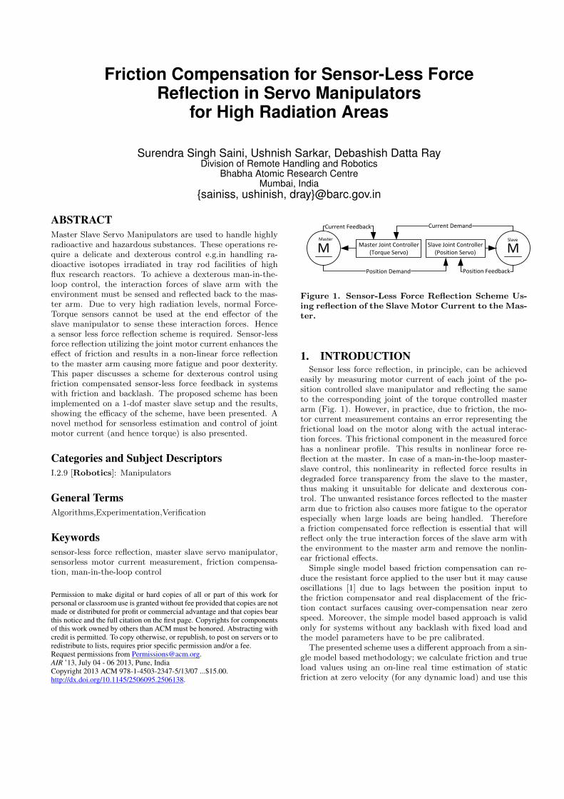
3.2.1 Steady Non-Zero Speed CompensationFor steady nonzero speeds of a joint, friction has a bi-
jective mathematical relation as given by the ‘General Ki-netic Friction Model’ (for non-zero speeds) as is evidentfrom equations (1) and (2). The parameters of this modelcan be found by regression analysis of the data plotted inFig. 2 which shows the speed of the joint motor (withzero/balanced external loads) as a function of the currentdrawn by the joint motor.
To do so, we give constant current to the motor, the motorwill then accelerate through a constant torque (the torque
0
200
400
600
800
1000
1200
1400
1600
1800
2000
0 100 200 300 400 500
Spe
ed
(rp
m)
Current (mA)
0g 10g 20g
30g 40g 50g
60g 70g 80g
90g 100g
Figure 2. Speed in Revolutions Per Minute vs. theapplied Constant Current to the joint motor at dif-ferent Balanced Load values (g).

applied by the motor is equal to the current drawn by themotor multiplied by its torque constant). The speed of thejoint will saturate when the reaction torque due to frictionexactly balances the torque applied by the motor. Once weknow the relation of friction (balanced-load current) withspeed of the slave joints, it is easy to compensate friction forsteady speeds by subtracting the corresponding balanced-load current (calculated from the calibrated GKF model)from the measured value of the current before reflecting itto the master arm. It may be noted that for this work, sincewe have earlier established a dependence of the slave currentand its friction component with the drive’s duty cycle, theexperimental data as shown in Fig. 3 is actually used to dothe regression analysis and hence calibrate the GKF modelfor non-zero speeds.
0
50
100
150
200
250
300
350
400
0 200 400 600 800 1000 1200
δ f
rict
ion
Speed (rpm)
0g 10g 20g 30g
40g 50g 60g 70g
80g 90g 100g
Figure 3. Component of the Duty cycle of the motordrive corresponding to friction vs. Speed in Revolu-tions Per Minute at different Balanced Load values(g).
3.2.2 Zero Speed CompensationWhen the slave manipulator is exerting force on the envi-
ronment but the slave arm is not moving and the positioncontroller of the slave joint has settled within it’s dead-band,the zero-speed compensation algorithm will come into effect.To elaborate the effect of a non-compensated force reflectionat zero speed, consider a single joint test setup with a bal-anced arm with vertical plane of rotation. Now keeping theload at the end tip constant, we gave the slave arm stepinputs of motion from zero degrees to 90 degrees measuredfrom the vertically downward axis and repeated this opera-tion several times. With iteration, as the position controllersettles the joint to 90 degrees and balances the weight ofthe load, the steady state current drawn by the motor isdifferent for different trials (Fig. 4). This can be explainedby the fact that the difference of the torque applied by thejoint motor and by the external load is being balanced bythe friction of the joint and the frictional component has adiscontinuity at zero speed.
The zero-speed compensation algorithm measures the presentvalue of the joint motor current and reflects it to the master.We then increase the amount of current given to the slavejoint motor in small steps and observe if there is any motion(in the pre-sliding displacement regime). If there were nodisplacement, we shall increase the slave joint motor cur-rent again and will continue to do so unless we achieve somenon-zero speed. We will measure the value of current atwhich the motion just occurred (breakaway) and will callthis value Imax. We shall now call the slave position con-troller again and wait for it to settle to the previous position
0
100
200
300
400
500
600
700
800
900
0 5 10 15 20 25
Cu
rre
nt
(mA
)
Event Number
Figure 4. Steady state current for different trialsfor a step input of 90 degrees for a fixed load of 100grams.
set point. Once the position controller has again settled, wewill start decreasing the current given to the joint motorand shall continue to do so in small steps until the motionjust starts. At the point where the motion just occurs in thereverse direction, we will note the current value again andcall that as Imin. The algorithm assumes that the effect offriction is isotropic for movement of the slave joint in bothdirections. Now we calculate ILoad (Friction CompensatedTorque Load at zero speed) and FLoad (The magnitude ofthe Static Friction corresponding to the weight taken by thejoint axis) using the following equations.
ILoad = (Imin + Imax)/2 (9)
FLoad =|ILoad − Imin|+ |ILoad − Imax|
2(10)
The techniques discussed in subsections 1) and 2) are illus-trated through the flow chart in Fig. 5
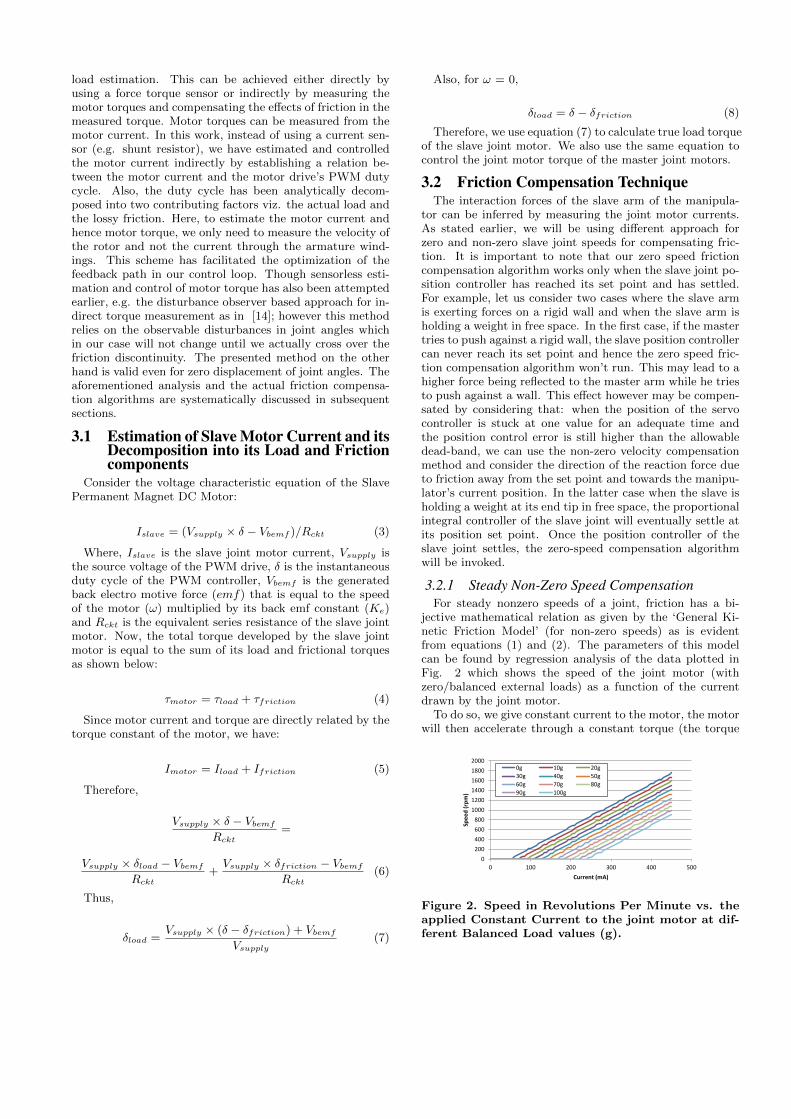
4. RESULTS AND DISCUSSIONSThe algorithms discussed above have been implemented
on a 1-dof master slave setup (Fig. 6). Results have beenshown for both zero and non zero speed cases.
4.1 Friction Compensation Results at ZeroSpeed
The effectiveness of our algorithmic friction compensationscheme at zero-speed was tested with various load values. Aparticular case is when we attach a load to the slave armwhen it is hanging vertically downwards, i.e. the angle of thearm (θ) from the vertically downward axis is zero degrees.In this case, the gravity load of any external weight will notcause any torque load to the joint (since the force due togravity is in radial direction) and hence the reflected torquesensed by our compensated reflector should be zero.
As the plot in Fig. 7 shows, we have been able to compen-sate the effects of frictional discontinuity and reflect the trueload. This would not have been the case if we just reflect theinstantaneous motor current without compensation. With-out friction compensation, the reflected load can take anyvalue between the Non-compensated minima and maximavalues of the current for the corresponding weight. This isbecause the Servo Position Controller may lock itself at anyvalue between these limits of current values. This behaviorcan be justified by the fact that: as long as the magnitudeof the difference, between the Load Torque and the Motor
Start
Load
Look-Up-Table
Set
Current FLoad = 0
Calculate Slave
V = d(θ)/dt and
Run Slave PID
Is V = 0
For > last 20 PID
cycles
Calculate ILoad
using V and LUT
for Current FLoad
Read Slave
Joint Angle (θ)
Read Master
Joint Angle
Send ILoad
to Master
Increase I by one step
Read Slave
Joint Angle (θ)
Has Slave Joint
angle Increased
Store I as Imax and
Decrease I by one
step and Toggle
mode to Min
Read Slave
Joint Angle
(θ)
Has Slave Joint
angle Decreased
Store I as Imin and
Increase I by one
step and Toggle
mode to Max
Calculate
Iload = (Imin+Imax)/2
Set Current FLoad =
(|Iload-Imin|+|Iload-Imax|)/2
No
No
Yes
is mode = Max
Yes
Yes
Decrease I by one step
No
No
Yes
Figure 5. Flow chart for friction compensation pro-cess.
Torque, is less than the maximum value of static friction,the reaction due to friction is exactly equal and opposite tothe said difference. Therefore, in the aforementioned case,the position of the joint (and hence its position sensors) willnot change until either the actual load or the motor currentchanges by a magnitude sufficient to overcome the staticfriction. Hence, in a general case, the residual steady statecurrent in the slave motor, even without any external tan-gential force on the slave arm is not zero, but can be anyvalue within the limits of the static friction.
At any angle other than zero, we shall have a net ex-ternal tangential force i.e. an external torque on the slavearm. Therefore, as we increase the weight on the slave armtip, both the static friction force (FLoad), and the externaltorque (ILoad) on the slave arm increases. Without a goodcompensation strategy, the amount of force reflected to themaster arm could again be any value between the rangesof static maximum friction for that load. In this work, theboundary conditions for the joint angle (θ) viz. 0 and 90degrees have been taken to experimentally contrast the ef-fect of uncompensated and compensated load and frictionvalues.
The results of the performance of compensation algorithmfor the trial using different loads are tabulated below in Ta-ble I. Fig 8 shows the same information for the convenienceof visualization. Fig 9 shows the compensated Slave loadcurrent value for different loads at θ = 90 degrees along with
Figure 6. The 1 - Degree of Freedom Master SlaveTest Setup.
-300
-200
-100
0
100
200
300
0 20 40 60 80 100 120
Cu
rre
nt
(mA
)
Load (g)
Compensated Current
Non-Compensated Minima
Non-Compensated Maxima
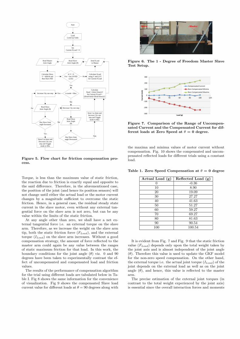
Figure 7. Comparison of the Range of Uncompen-sated Current and the Compensated Current for dif-ferent loads at Zero Speed at θ = 0 degree.
the maxima and minima values of motor current withoutcompensation. Fig. 10 shows the compensated and uncom-pensated reflected loads for different trials using a constantload.
Table 1. Zero Speed Compensation at θ = 0 degree
Actual Load (g) Reflected Load (g)0 -0.3610 8.9020 19.0930 27.2740 41.6350 51.2760 59.2770 69.2780 81.6390 90.54100 100.54
It is evident from Fig. 7 and Fig. 9 that the static frictionvalue (FLoad) depends only upon the total weight taken bythe joint axis and is almost independent of the joint angle(θ). Therefore this value is used to update the GKF modelfor the non-zero speed compensation. On the other hand,the external torque i.e. the actual joint torque (ILoad) of thejoint depends on the external load as well as on the jointangle (θ), and hence, this value is reflected to the masterarm.
The precise estimation of the external joint torques (incontrast to the total weight experienced by the joint axis)is essential since the overall interaction forces and moments

at the end effector are calculated by using the relation F =
(JT )−1T . Where, F is the matrix depicting the forces and
moments of interaction at the manipulator’s end effector,
(JT )−1
is the inverse of the transpose of the Jacobian of theslave joint of the manipulator and T is the matrix of all theexternal joint torques of the slave manipulator [15].
-20
0
20
40
60
80
100
120
1 2 3 4 5 6 7 8 9 10 11
Load
(g)
Trial No.
Actual Load
Reflected Load
Figure 8. Zero Speed Compensation at θ = 90 de-grees.
-100
0
100
200
300
400
500
600
700
800
900
0 20 40 60 80 100 120
Cu
rre
nt
(mA
)
Load (g)
Compensated Current
Non-Compensated Minima
Non-Compensated Maxima
Figure 9. Comparison of Compensated Current andUncompensated Current range at Zero Speed at θ= 90 degrees for different loads.
0
10
20
30
40
50
60
70
0 2 4 6 8 10 12
Load
(g)
Trial No.
Actual Load (g)
Compensated Reflected Load (g)
Uncompensated Reflected Load (g)
Figure 10. Comparison of Compensated Currentand Uncompensated Current at zero speed at θ =90 degrees for a constant load.
4.2 Compensation for Steady Nonzero SpeedsKeeping the load constant, for varying steady state speeds,
a comparative study of compensated and uncompensatedreflected load current has been presented in Fig. 11.
5. CONCLUSIONFriction compensation makes the task of manipulation
more dexterous by reducing the unwanted nonlinear fric-tional force from being reflected to the master arm. The
0
10
20
30
40
50
60
70
0 200 400 600 800 1000 1200
Load
(g)
Steady State Speed (rpm)
Actual Load (g)
Compensated Reflected Load (g)
Uncompensated Reflected Load (g)
Figure 11. Comparison of Compensated and Un-compensated Current for a constant load at differentsteady state speeds.
scheme used here is best suitable for the requirements ofa Man-in-the-loop type medium-capacity electrical master-slave system designed for use in high radiation areas withmore allowable limits of backlash but lower friction limitsand may not be suitable to standard industrial robots thathave very low amount of backlash (but higher joint friction)to achieve better repeatability. In this work, we have verifiedboth zero speed and constant speed friction compensatedforce reflection. For cases involving a reversal in the direc-tion of motion of these high inertia systems, there exists afinite span of zero velocity regime before attaining a veloc-ity of the opposite sign. During this span of zero velocity,the zero speed compensation takes place, compensating theeffects of friction and backlash. For cases involving acceler-ated motion, the pseudo force due to a non-inertial frameof reference will be added to the actual load. Although,the same compensation methodology was used for the non-uniform motion and is theoretically valid for such a domain,the experimental verification remains as a future work.
6. REFERENCES
[1] Mahavash M., Dokamura A. M. 2006. Friction Com-pensation for a Forcefeedbacktelerobotic System. InProceedings of the IEEE International Conference onRobotics and Automation. (Orlando, FL, 2006), 3268-3273. DOI = 10.1109/ROBOT.2006.1642200
[2] Dahl P. R. 1968. A Solid Friction Model. TechnicalReport TOR-0158(3107-18)-1. The Aerospace Corpo-ration, El Segundo, CA.
[3] Armstrong-Helouvry, Brian. 1991. Control of ma-chines with friction. Springer ISBN: 0-7923-9133-0USA. DOI = 10.1007/978-1-4615-3972-8 2.
[4] Armstrong-Helouvry, B., Dupont P., and Canudas deWit, C. 1994. A Survey of Models, Analysis Toolsand Compensation Methods for the Control of Ma-chines with Friction. Automatica 30,7 (July 1994).1083-1138. DOI = 10.1016/0005-1098(94)90209-7.
[5] Makkar, C., Dixon, W. E., Sawyer, W. G., and Hu,G. 2005. A new continuously differentiable fric-tion model for control systems design. In Proceed-ings of the IEEE/ASME Int. Conf. on Adv. IntelligentMechatronics. (Monterey, CA, 2005), 600-605. DOI =10.1109/AIM.2005.1511048.

[6] Misovec, K. M., and Annaswamy, A. M. 1998. Fric-tion Compensation Using Adaptive Nonlinear Con-trol with Persistant Excitation. In Proceedings ofthe Amer. Contr. Conf. 3 (1998), 1483-1487. DOI =10.1109/ACC.1998.707074.
[7] Stribeck, R. 1902 Die wesentlichenEigenschaftender Gleit - und Rollenlager (The basic properties ofsliding and rolling bearings). Zeitschrift des Vereins-DeutscherIngenieure, 46 (1902), 1341-1348, 1432-1438and 1463-1470.
[8] Garcia, E., Gonzalez, P., and De Wit, C. 2002. Ve-locity dependence in the cyclic friction arising withgears. Int. J. Robot. Res. 21, 9 (2002), 761-771.
[9] Haessig, Jr, D. A., and Friedland, B. 1991. On themodeling and simulation of friction. Trans. ASME, J.Dyn. Syst. Meas. Control , 113, 3 (Sept. 1991), 354-3962.
[10] Astrom K. J., and Canudas-De-Wit, C. 2008. Revis-iting the LuGre Friction Model. IEEE Control SystemsMagazine. 28, 6 (2008), 101-114.
[11] Bliman, P. A., and Sorine, M. 1995. Easy-to-use Re-alistic Dry Friction Models for Automatic Control. InProceedings of the 3rd European. Control Conference,ECC’95 (Rome, Italy, 1995), 3788-3794.
[12] Canudas de Wit, C., Olsson, H. K., Astrom, J., andP. Lischinsky. 1995. A New Model for Control ofSystems with Friction. IEEE Transactions AutomaticControl. 40, 3 (Mar. 1995), 419-425.
[13] Ray, DD, and Singh, M. 2010. Development ofa Force Reflecting Tele-robot for Remote Handlingin Nuclear Installations. In Proceedings of the 1stInternationalConference on Applied Robotics for thePower Industry (Montreal, Canada, 2010), 1-6. DOI= 10.1109/CARPI.2010.5624456.
[14] Murakami, Toshiyuki, Yu, Fangming, and Ohnishi,Kouhei. 1993. Torque Sensorless Control inMultidegree-of-Freedom Manipulator. IEEE Transac-tions on Industrial Electronics. 40, 2 (1993), 259-265.
[15] Craig, John J. 1989. Introduction to Robotics: Me-chanics and Control. (2nd Edition), Addison-WesleyPublishing Company ISBN:0-201-09528-9.