Embed Size (px)
Citation preview
www.vektek.com 800-992-0236 © Vektek, February 2017
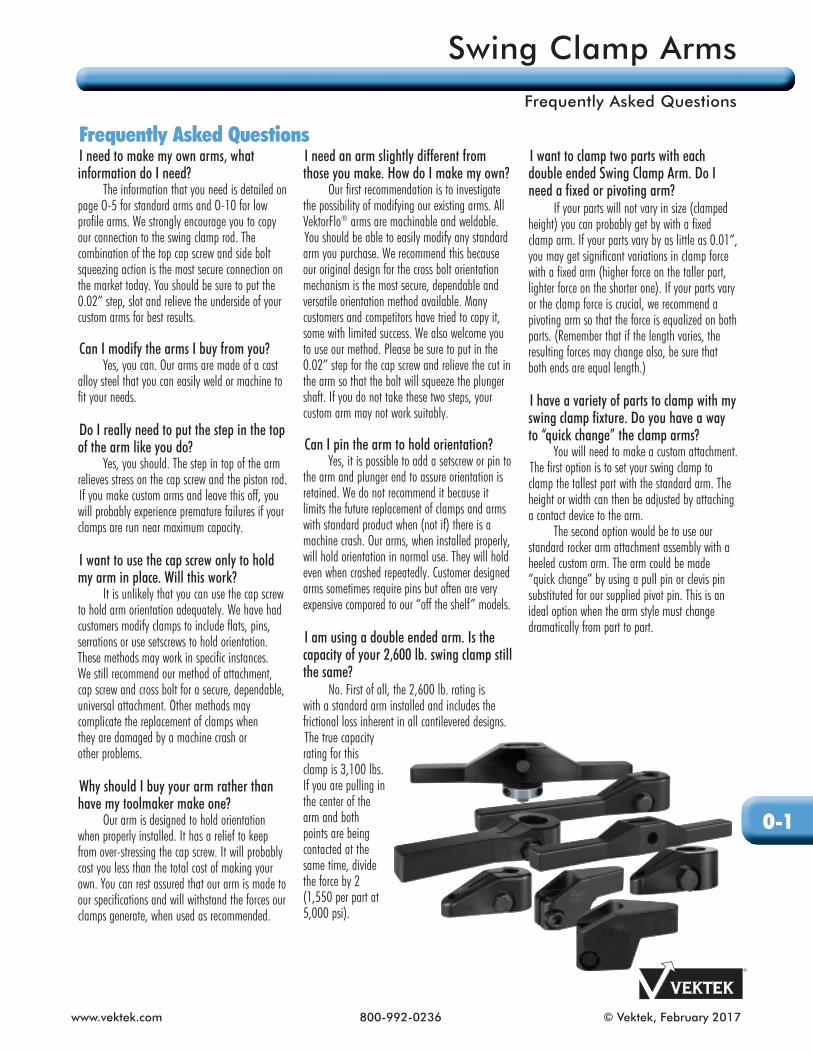
Frequently Asked QuestionsI need to make my own arms, what information do I need?
The information that you need is detailed on page O-5 for standard arms and O-10 for low profile arms. We strongly encourage you to copy our connection to the swing clamp rod. The com bi na tion of the top cap screw and side bolt squeezing action is the most secure connection on the market today. You should be sure to put the 0.02” step, slot and relieve the un der side of your custom arms for best results.
Can I modify the arms I buy from you? Yes, you can. Our arms are made of a cast
alloy steel that you can easily weld or machine to fit your needs.
Do I really need to put the step in the top of the arm like you do?
Yes, you should. The step in top of the arm relieves stress on the cap screw and the piston rod.If you make custom arms and leave this off, you will probably experience pre ma ture failures if your clamps are run near maximum capacity.
I want to use the cap screw only to hold my arm in place. Will this work?
It is unlikely that you can use the cap screw to hold arm orientation ad e quate ly. We have had customers modify clamps to include flats, pins, serrations or use setscrews to hold orientation. These methods may work in specific instances. We still rec om mend our method of attachment, cap screw and cross bolt for a secure, dependable, universal attachment. Other methods may complicate the replacement of clamps when they are damaged by a machine crash or other problems.
Why should I buy your arm rather than have my tool mak er make one?
Our arm is designed to hold orientation when properly installed. It has a relief to keep from over-stressing the cap screw. It will probably cost you less than the total cost of making your own. You can rest assured that our arm is made to our spec i fi ca tions and will withstand the forces our clamps generate, when used as recommended.
I need an arm slightly different from those you make. How do I make my own? Our first recommendation is to investigate the possibility of modifying our existing arms. All VektorFlo® arms are machinable and weldable.You should be able to easily modify any standard arm you purchase. We recommend this because our original design for the cross bolt orientation mechanism is the most secure, dependable and ver sa tile orientation method available. Many customers and competitors have tried to copy it, some with limited success. We also welcome you to use our method. Please be sure to put in the 0.02” step for the cap screw and relieve the cut in the arm so that the bolt will squeeze the plunger shaft. If you do not take these two steps, your custom arm may not work suitably.
Can I pin the arm to hold orientation? Yes, it is possible to add a setscrew or pin to the arm and plunger end to assure orientation is retained. We do not rec om mend it because it limits the future replacement of clamps and arms with standard product when (not if) there is a machine crash. Our arms, when installed properly, will hold orientation in normal use. They will hold even when crashed repeatedly. Customer designed arms sometimes require pins but often are very expensive compared to our “off the shelf” models.
I am using a double ended arm. Is the capacity of your 2,600 lb. swing clamp still the same? No. First of all, the 2,600 lb. rating is with a standard arm installed and includes the frictional loss inherent in all can ti le vered designs.The true capacity rating for this clamp is 3,100 lbs. If you are pulling in the center of the arm and both points are being contacted at the same time, divide the force by 2 (1,550 per part at 5,000 psi).
I want to clamp two parts with each double ended Swing Clamp Arm. Do I need a fixed or pivoting arm? If your parts will not vary in size (clamped height) you can probably get by with a fixed clamp arm. If your parts vary by as little as 0.01”, you may get sig nif i cant variations in clamp force with a fixed arm (higher force on the taller part, lighter force on the shorter one). If your parts vary or the clamp force is crucial, we recommend a pivoting arm so that the force is equalized on both parts. (Re mem ber that if the length varies, the resulting forces may change also, be sure that both ends are equal length.)
I have a variety of parts to clamp with my swing clamp fixture. Do you have a way to “quick change” the clamp arms? You will need to make a custom attachment. The first option is to set your swing clamp to clamp the tallest part with the standard arm. The height or width can then be adjusted by attaching a contact device to the arm. The second option would be to use our standard rocker arm attachment assembly with a heeled custom arm. The arm could be made “quick change” by using a pull pin or clevis pin substituted for our supplied pivot pin. This is an ideal option when the arm style must change dra mat i cal ly from part to part.
O-1
Swing Clamp Arms
Frequently Asked Questions
© Vektek, August 2017 800-992-0236 www.vektek.com
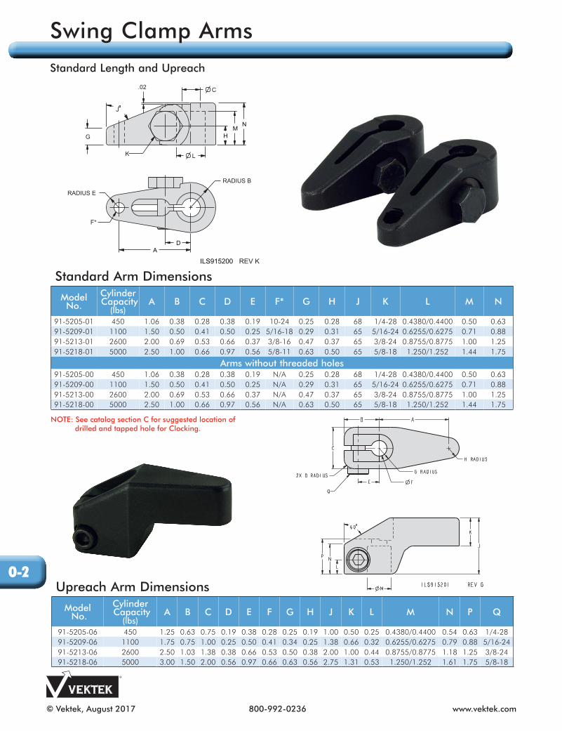
Standard Arm Dimensions
Model No.
Cylinder Capacity
(lbs)A B C D E F* G H J K L M N
91-5205-01 450 1.06 0.38 0.28 0.38 0.19 10-24 0.25 0.28 68 1/4-28 0.4380/0.4400 0.50 0.6391-5209-01 1100 1.50 0.50 0.41 0.50 0.25 5/16-18 0.29 0.31 65 5/16-24 0.6255/0.6275 0.71 0.8891-5213-01 2600 2.00 0.69 0.53 0.66 0.37 3/8-16 0.47 0.37 65 3/8-24 0.8755/0.8775 1.00 1.2591-5218-01 5000 2.50 1.00 0.66 0.97 0.56 5/8-11 0.63 0.50 65 5/8-18 1.250/1.252 1.44 1.75
Arms without threaded holes91-5205-00 450 1.06 0.38 0.28 0.38 0.19 N/A 0.25 0.28 68 1/4-28 0.4380/0.4400 0.50 0.6391-5209-00 1100 1.50 0.50 0.41 0.50 0.25 N/A 0.29 0.31 65 5/16-24 0.6255/0.6275 0.71 0.8891-5213-00 2600 2.00 0.69 0.53 0.66 0.37 N/A 0.47 0.37 65 3/8-24 0.8755/0.8775 1.00 1.2591-5218-00 5000 2.50 1.00 0.66 0.97 0.56 N/A 0.63 0.50 65 5/8-18 1.250/1.252 1.44 1.75
Upreach Arm Dimensions
Model No.
Cylinder Capacity
(lbs)A B C D E F G H J K L M N P Q
91-5205-06 450 1.25 0.63 0.75 0.19 0.38 0.28 0.25 0.19 1.00 0.50 0.25 0.4380/0.4400 0.54 0.63 1/4-2891-5209-06 1100 1.75 0.75 1.00 0.25 0.50 0.41 0.34 0.25 1.38 0.66 0.32 0.6255/0.6275 0.79 0.88 5/16-2491-5213-06 2600 2.50 1.03 1.38 0.38 0.66 0.53 0.50 0.38 2.00 1.00 0.44 0.8755/0.8775 1.18 1.25 3/8-2491-5218-06 5000 3.00 1.50 2.00 0.56 0.97 0.66 0.63 0.56 2.75 1.31 0.53 1.250/1.252 1.61 1.75 5/8-18
A
RADIUS E
G
RADIUS B
J
D
MN
H
.02
L
C
ILS915200 REV K
K
F*
NOTE: See catalog section C for suggested location of drilled and tapped hole for Clocking.
O-2
Swing Clamp Arms
Standard Length and Upreach

www.vektek.com 800-992-0236 © Vektek, February 2017
Arm lengths and pressures operating at or below the curves shown are in the safe operating zones for the clamp model indicated.
NOTE: Please reference Clamp Times and Flow and C-2 for TuffCam™ or C-26 for Standard Swing Clamps.
Extended Arm Dimensions
Model No.
CylinderCapacity
(lbs)A B C D E F G H J K L M N
91-5205-02 450 3.25 1.07 0.38 0.28 0.38 0.41 0.34 22˚ 0.28 1/4-28 0.4380/0.4400 0.50 0.6391-5209-02 1100 5.37 1.32 0.50 0.41 0.50 0.56 0.50 25˚ 0.31 5/16-24 0.6255/0.6275 0.71 0.8891-5213-02 2600 6.37 2.03 0.69 0.53 0.66 0.75 0.63 25˚ 0.37 3/8-24 0.8755/0.8775 1.00 1.2591-5218-02 5000 6.50 2.80 1.00 0.66 0.97 1.13 0.75 25˚ 0.50 5/8-18 1.250/1.252 1.44 1.75
O-3
Swing Clamp Arms
Extended, Arm Length and Pressure Limitations

© Vektek, February 2017 800-992-0236 www.vektek.com
Double Ended DimensionsModel No.
CylinderCapacity
(lbs)A B C D E F G H J K L M N P
91-5205-07 450 2.75 5.50 1.07 0.38 0.41 0.28 0.38 22 0.28 1/4-28 0.4380/0.4400 0.50 0.34 0.6391-5209-07 1100 4.37 8.75 1.32 0.50 0.56 0.41 0.50 25 0.31 5/16-24 0.6255/0.6275 0.71 0.50 0.8891-5213-07 2600 5.37 10.75 2.03 0.69 0.75 0.53 0.66 25 0.37 3/8-24 0.8755/0.8775 1.00 0.63 1.2591-5218-07 5000 5.50 11.00 2.80 1.00 1.13 0.66 0.97 25 0.50 5/8-18 1.250/1.252 1.44 0.75 1.75
O-4
Swing Clamp Arms
Double Ended
www.vektek.com 800-992-0236 © Vektek, February 2017
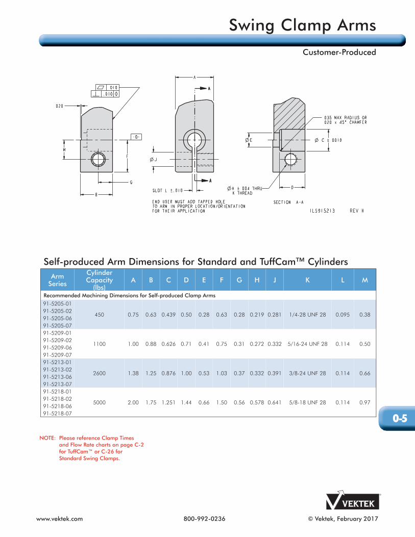
Self-produced Arm Dimensions for Standard and TuffCam™ CylindersArm
Series
Cylinder Capacity
(lbs)A B C D E F G H J K L M
Recommended Machining Dimensions for Self-produced Clamp Arms
91-5205-01
450 0.75 0.63 0.439 0.50 0.28 0.63 0.28 0.219 0.281 1/4-28 UNF 28 0.095 0.3891-5205-0291-5205-0691-5205-0791-5209-01
1100 1.00 0.88 0.626 0.71 0.41 0.75 0.31 0.272 0.332 5/16-24 UNF 28 0.114 0.5091-5209-0291-5209-0691-5209-0791-5213-01
2600 1.38 1.25 0.876 1.00 0.53 1.03 0.37 0.332 0.391 3/8-24 UNF 28 0.114 0.6691-5213-0291-5213-0691-5213-0791-5218-01
5000 2.00 1.75 1.251 1.44 0.66 1.50 0.56 0.578 0.641 5/8-18 UNF 28 0.114 0.9791-5218-0291-5218-0691-5218-07
NOTE: Please reference Clamp Times and Flow Rate charts on page C-2 for TuffCam™ or C-26 for Standard Swing Clamps.
O-5
Swing Clamp Arms
Customer-Produced

© Vektek, February 2017 800-992-0236 www.vektek.com
Double Ended Rocker Arm DimensionsModel No.
CylinderCapacity
(lbs)A B C D E F G H J K L M N P
91-5205-09 450 2.13 4.25 0.38 0.63 0.41 0.25 0.36 0.18 13˚ 0.250 0.23 0.34 0.46 0.9691-5209-09 1100 3.00 6.00 0.48 0.88 0.56 0.38 0.50 0.25 18˚ 0.312 0.38 0.50 0.75 1.2791-5213-09 2600 4.25 8.50 0.73 1.25 0.75 0.53 0.70 0.35 25˚ 0.437 0.55 0.63 1.10 1.7891-5218-09 5000 5.50 11.00 0.98 2.00 1.12 0.78 1.00 0.50 30˚ 0.624 0.87 0.75 1.75 2.86
Rocker Arm Attachment Assembly DimensionsModel No.
CylinderCapacity
(lbs)A B C D E F G H J K L M N P
91-5205-08 450 1/4-28 0.437 0.26 0.58 0.81 1.06 0.243 0.94 6-32 Ø0.250 X 0.63 0.88 0.16 0.38 0.0691-5209-08 1100 3/8-24 0.625 0.33 0.76 1.14 1.58 0.370 1.31 10-32 Ø0.313 X 0.88 1.25 0.19 0.44 0.2291-5213-08 2600 1/2-20 0.875 0.30 1.05 1.59 2.09 0.524 1.63 1/4-28 Ø0.438 X 1.25 1.63 0.25 0.50 0.2591-5218-08 5000 5/8-18 1.250 0.40 1.43 2.24 2.88 0.780 2.06 1/4-28 Ø0.625 X 2.00 2.00 0.25 0.50 0.37
O-6
Swing Clamp Arms
Double Ended Rocker
www.vektek.com 800-992-0236 © Vektek, April 2018
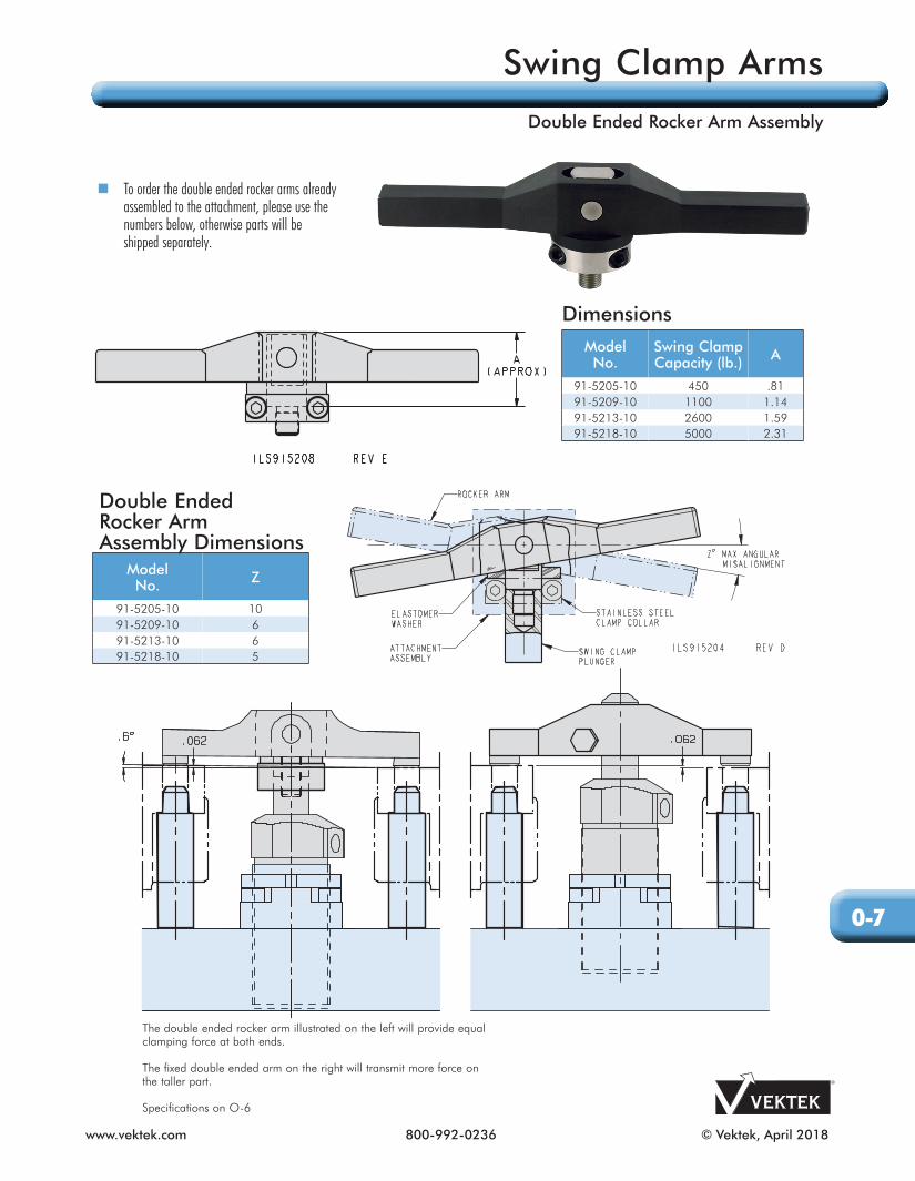
The double ended rocker arm illustrated on the left will provide equal clamping force at both ends.
The fixed double ended arm on the right will transmit more force on the taller part.
Specifications on O-6
To order the double ended rocker arms already assembled to the attachment, please use the numbers below, otherwise parts will be shipped separately.
Double Ended Rocker Arm Assembly Dimensions
Model No. Z
91-5205-10 1091-5209-10 691-5213-10 691-5218-10 5
DimensionsModel No.
Swing Clamp Capacity (lb.) A
91-5205-10 450 .8191-5209-10 1100 1.1491-5213-10 2600 1.5991-5218-10 5000 2.31
O-7
Swing Clamp Arms
Double Ended Rocker Arm Assembly
© Vektek, February 2017 800-992-0236 www.vektek.com
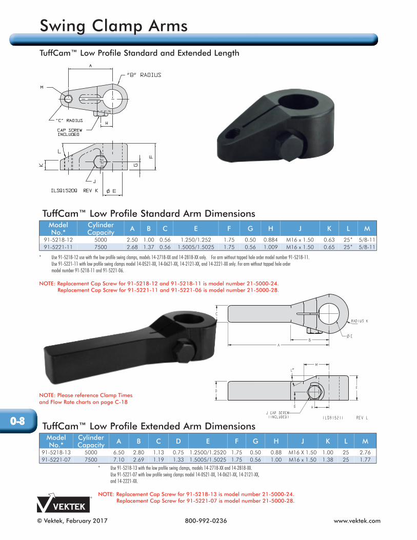
* Use 91-5218-12 use with the low profile swing clamps, models 14-2718-XX and 14-2818-XX only. For arm without tapped hole order model number 91-5218-11. Use 91-5221-11 with low profile swing clamps model 14-0521-XX, 14-0621-XX, 14-2121-XX, and 14-2221-XX only. For arm without tapped hole order model number 91-5218-11 and 91-5221-06.
NOTE: Replacement Cap Screw for 91-5218-12 and 91-5218-11 is model number 21-5000-24. Replacement Cap Screw for 91-5221-11 and 91-5221-06 is model number 21-5000-28.
TuffCam™ Low Profile Standard Arm DimensionsModel No.*
Cylinder Capacity A B C E F G H J K L M
91-5218-12 5000 2.50 1.00 0.56 1.250/1.252 1.75 0.50 0.884 M16 x 1.50 0.63 25˚ 5/8-1191-5221-11 7500 2.68 1.37 0.56 1.5005/1.5025 1.75 0.56 1.009 M16 x 1.50 0.65 25˚ 5/8-11
TuffCam™ Low Profile Extended Arm DimensionsModel No.*
Cylinder Capacity A B C D E F G H J K L M
91-5218-13 5000 6.50 2.80 1.13 0.75 1.2500/1.2520 1.75 0.50 0.88 M16 X 1.50 1.00 25 2.7691-5221-07 7500 7.10 2.69 1.19 1.33 1.5005/1.5025 1.75 0.56 1.00 M16 x 1.50 1.38 25 1.77
NOTE: Please reference Clamp Times and Flow Rate charts on page C-18
* Use 91-5218-13 with the low profile swing clamps, models 14-2718-XX and 14-2818-XX. Use 91-5221-07 with low profile swing clamps model 14-0521-XX, 14-0621-XX, 14-2121-XX, and 14-2221-XX.
NOTE: Replacement Cap Screw for 91-5218-13 is model number 21-5000-24. Replacement Cap Screw for 91-5221-07 is model number 21-5000-28.
O-8
Swing Clamp Arms
TuffCam™ Low Profile Standard and Extended Length

www.vektek.com 800-992-0236 © Vektek, September 2017
TuffCam™ Low Profile Upreach Arm DimensionsModel No.*
CylinderCapacity A B C D E F G H J K L M N
91-5218-15 5000 3.00 2.00 0.56 0.56 1.250/1.252 2.75 1.44 0.53 0.884 M16 x 1.50 1.61 1.75 1.5091-5221-09 7500 3.19 2.75 0.56 0.56 1.5005/1.5025 3.00 1.56 0.53 1.009 M16 x 1.50 1.77 1.75 1.62
TuffCam™ Low Profile Double Ended Arm DimensionsModel No.
CylinderCapacity A 2A B C D E F G H J K L
91-5218-14* 5000 5.50 11.00 2.80 1.13 0.75 1.250/1.252 1.75 0.50 0.884 M16 X 1.50 0.63 2591-5221-08** 7500 7.10 14.20 1.75 1.19 1.33 1.5005/1.5025 1.75 0.56 1.009 M16 X 1.50 0.65 25
* Use 91-5218-15 with the low profile swing clamps, models 14-2718-XX and 14-2818-XX only. Use 91-5221-09 with low profile swing clamps model 14-0521-XX, 14-0621-XX, 14-2121-XX, and 14-2221-XX only.
NOTE: Replacement Cap Screw for 91-5218-15 and 91-5221-09 is model number 21-5000-25.
* Use 91-5218-14 with the low profile swing clamps, models 14-2718-XX and 14-2818-XX only. For arm without tapped hole order Model Number 91-5218-11.** Use 91-5221-08 with low profile swing clamps model 14-0521-XX, 14-0621-XX, 14-2121-XX, and 14-2221-XX only.
NOTE: Replacement Cap Screw for 91-5218-14 is model number 21-5000-24. Replacement Cap screw for 91-5221-08 is model number 21-5000-28.
C (TYP)
D (TYP)
L°
K RADIUS
F
B (TYP)
H
G
2AA
E
ILS915212 REV JJ (CAP SCREW INCLUDED)
O-9
Swing Clamp Arms
TuffCam™ Low Profile Upreach and Double Ended

© Vektek, February 2017 800-992-0236 www.vektek.com
Self-produced Low Profile Arm Dimensions
Arm Series
CylinderCapacity
(lbs)A B C D E F G H J
Recommended Machining Dimensions for Self-produced Clamp Arm91-5218-12
5000 2.00 1.75 1.251 1.00 0.50 0.57 0.65 M16 x 1.50-6H 2.0691-5218-1391-5218-1491-5221-07
7500 2.75 1.75 1.5015 1.38 0.56 0.57 0.65 M16 x 1.50-6H 2.2591-5221-0891-5221-11
Arm Series
Cylinder Capacity
(lbs)K L M S T U V W
X
S/A D/ARecommended Machining Dimensions for Self-produced Clamp Arm91-5218-12
5000 0.11 1.00 0.80 0.51 0.88 1.38 0.25 1.01 1.70 1.2991-5218-1391-5218-1491-5221-07
7500 0.12 1.12 0.57 0.56 1.00 1.38 0.38 1.00 2.00 1.2291-5221-0891-5221-11
NOTE: Please reference Clamp Times and Flow Rate charts on page C-18.
Hex head cap screw for standard, extended and double ended arms: *Arm series 91-5218-12, 915218-13, 91-5218-14 is model number 21-5000-24. *Arm series 91-5221-07, 91-5221-08, 91-5221-11 is model number 21-5000-28
O-10
Swing Clamp Arms
Customer Produced TuffCam™ Low Profile