Embed Size (px)
Citation preview
Frequent Patterns in ETL Workflows: An Empirical Approach
Vasileios Theodoroua,∗, Alberto Abelloa, Maik Thieleb, Wolfgang Lehnerb
aUniversitat Politecnica de Catalunya, Barcelona, SpainbTechnische Universitat Dresden, Dresden, Germany
Abstract
The complexity of Business Intelligence activities has driven the proposal of several ap-proaches for the effective modeling of Extract-Transform-Load (ETL) processes, based onthe conceptual abstraction of their operations. Apart from fostering automation and main-tainability, such modeling also provides the building blocks to identify and represent fre-quently recurring patterns. Despite some existing work on classifying ETL components andfunctionality archetypes, the issue of systematically mining such patterns and their connec-tion to quality attributes such as performance has not yet been addressed. In this work, wepropose a methodology for the identification of ETL structural patterns. We logically modelthe ETL workflows using labeled graphs and employ graph algorithms to identify candidatepatterns and to recognize them on different workflows. We showcase our approach througha use case that is applied on implemented ETL processes from the TPC-DI specification andwe present mined ETL patterns. Decomposing ETL processes to identified patterns, ourapproach provides a stepping stone for the automatic translation of ETL logical models totheir conceptual representation and to generate fine-grained cost models at the granularitylevel of patterns.
Keywords: ETL, patterns, empirical, graph matching
1. Introduction
Extract, Transform and Load (ETL) processes are crucial business processes that re-quire heavy investments for their design, deployment and maintenance. With data beingincreasingly recognized as a key asset for the success of any enterprise, interest is growing forthe development of more sophisticated models and tools to aid in data process automation5
and dynamicity. According to a recent Gartner report [1], the data integration tool marketis growing with an impressive rate, with an increase of 10.5% from 2014 to 2015 and anexpected total market revenue of $4 billion in 2020.
In this context, ETL requirements are becoming more advanced and demanding withexpectations such as self-service BI [2] and on-the-fly data processing making ETL projects10
even more complex. Moreover, ETL users and developers with different backgrounds, using
∗Corresponding authorEmail addresses: [email protected] (Vasileios Theodorou), [email protected] (Alberto
Abello), [email protected] (Maik Thiele), [email protected] (WolfgangLehner)
Preprint submitted to Data & Knowledge Engineering July 21, 2017
different models and technologies form a confusing landscape of ETL frameworks and pro-cesses that is hard to analyze and harness. The reply from academia has been the proposalof models (e.g., using the business process modeling notation (BPMN) [3] or the unifiedmodeling language (UML) [4]) that classify ETL functionalities in different levels of abstrac-15
tion, creating common ground for the description of ETL operations and fostering designautomation and analysis. On the direction of translating conceptual and logical operationsto physical implementations, the design and implementation of large ETL flows is detachedfrom the use of specific technologies and using tested structures and best practices, it canbecome more reliable, efficient and simple. On the opposite direction, mapping physical to20
logical and conceptual models allows for the concise representation and reuse of components,as well as different layers of analysis and comparison of ETL flows.
The proposed ETL modeling as well as the ETL logical view generated by different open-source and proprietary tools, expose an ETL workflow perspective that opens the door for theidentification and specification of ETL patterns. Although there have been some approaches25
on ETL patterns, considering most used ETL tasks or the morphology of the complete ETLflow, a bottom up methodology that can identify patterns and apply customized analysison a given generic set of ETL processes is still missing, making the practical exploitation ofETL patterns difficult.
In this work, we introduce our empirical approach for the identification of ETL structural30
patterns that are significant for different types of analysis. Based on the different types ofETL operations, we logically model the ETL workflows using labeled graphs and employgraph algorithms to identify candidate patterns and to recognize them on different workflows.For the identification phase, we use frequent subgraph discovery techniques and for therecognition phase, we introduce an algorithm that can perform very well for ETL flows and35
can scale for the cases of multiple and large flows.Our approach can be used for the (pre-)evaluation of alternative ETL workflows at design
time, without the need for their execution or simulation, but solely by decomposing themto recognized patterns for which quality characteristics are measured during a supervisedlearning phase. In addition, it can generate fine-grained cost models at the granularity level40
of patterns. It can also be used to classify reusable and well-defined ETL steps regardlessof the implementation technology in order to i) automatically derive more understandableconceptual modeling and visualization of ETLs and ii) improve the reusability and reliabilityof ETL components in cases of alternative pattern implementations by exposing their char-acteristics. To showcase our approach, we implement a set of realistic ETL processes defined45
in the TPC-DI benchmark and we show experimental results from applying our methodologyon them.
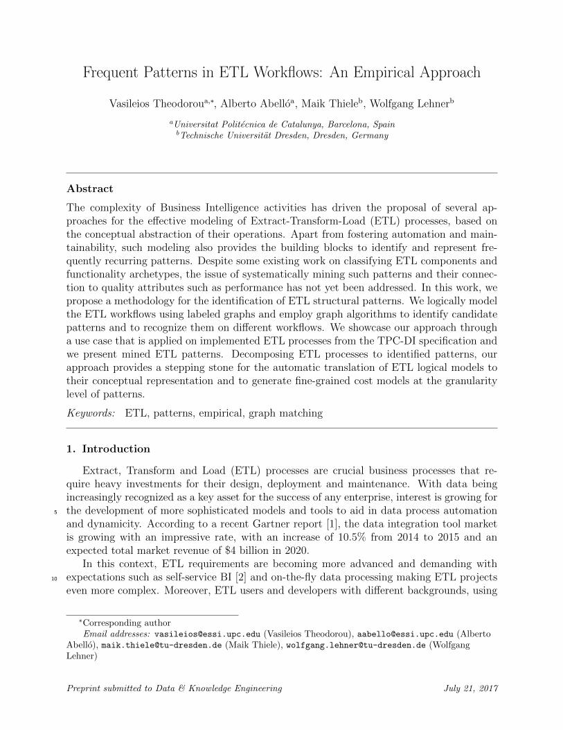
From the same domain (i.e., the TPC-DI benchmark), we adopt as our running toy ex-ample an ETL process (see Figure 1) that populates the FactCashBalances table duringthe Historical Load phase. In Figure 1, we show the logical view of the ETL process, as it50
is viewed from the implementation that we developed using the Pentaho Data Integration(PDI) open source tool. The ETL process extracts data from a plain-text file in the StagingArea (CashTransaction.txt) and processes one of its fields to remove time and keep onlydate information. Consequently, data are joined with DimAccount table to obtain the cor-responding keys for customers and accounts, after irrelevant fields from both sources have55
been projected out and data have been sorted. Similarly, data are joined with the DimDate
2
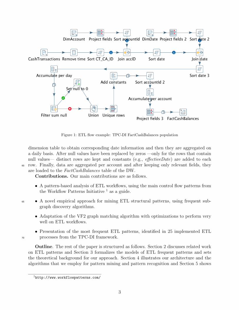
Figure 1: ETL flow example: TPC-DI FactCashBalances population
dimension table to obtain corresponding date information and then they are aggregated ona daily basis. After null values have been replaced by zeros —only for the rows that containnull values— distinct rows are kept and constants (e.g., effectiveDate) are added to eachrow. Finally, data are aggregated per account and after keeping only relevant fields, they60
are loaded to the FactCashBalances table of the DW.Contributions. Our main contributions are as follows.
• A pattern-based analysis of ETL workflows, using the main control flow patterns fromthe Workflow Patterns Initiative 1 as a guide.
• A novel empirical approach for mining ETL structural patterns, using frequent sub-65
graph discovery algorithms.
• Adaptation of the VF2 graph matching algorithm with optimizations to perform verywell on ETL workflows.
• Presentation of the most frequent ETL patterns, identified in 25 implemented ETLprocesses from the TPC-DI framework.70
Outline. The rest of the paper is structured as follows. Section 2 discusses related workon ETL patterns and Section 3 formalizes the models of ETL frequent patterns and setsthe theoretical background for our approach. Section 4 illustrates our architecture and thealgorithms that we employ for pattern mining and pattern recognition and Section 5 shows
1http://www.workflowpatterns.com/
3
results from applying our methodology on implemented ETLs. Finally, Section 6 presents75
two interesting use cases of a provided structured methodology while Section 7 concludesthe paper.
2. Related Work
There has been considerable work in the area of ETL modeling, in an effort to promoteautomation through the definition of structural abstractions and systematic methodologies80
for the design and analysis of ETL models. In [5], ETL activities are formally definedand classified and in [6], such activities are modeled as the interacting steps of workflowsin a multi-layered view that bridges conceptual to logical modeling and exposes qualitycharacteristics (denoted as QoX ). Similarly to the latter, the authors in [3] adapt the BPMNrepresentation for the conceptual view of the ETL flow and describe a systematic approach85
of code generation from BPMN models. In the same direction, [4] proposes a UML-basedframework where ETL activities constitute the block units of UML activity diagrams amongwhich there is control flow.
The modeling of ETL processes using well defined, reusable components interacting asworkflow activities has set the foundations for their pattern-based analysis and design. In90
the Business Process Management (BPM) community, such analysis has already taken place,with significant work conducted as part of the Workflow Patterns Initiative [7, 8]. Thiswork examines workflows and various different Workflow Management Systems (WfMSs)and identifies a set of recurring features (i.e., patterns). It takes under consideration themodeling languages used for the design and the modeling notation of business process models95
and extracts a number of patterns to describe mostly control-flow and data-flow semanticscommonly offered by WfMSs. In [9], there is a practical illustration of how such patternscan be introduced and integrated into an existing business process model and in [10], theapplication of patterns on a business process is linked to the strategic decision making level,through its mapping to business goals and non-functional requirements (NFRs).100
When it comes to patterns in ETL activities, in [11] there is a profiling of ETL workflowswith models called Butterflies, based on their form with regards to the distribution of ac-tivities relatively to the beginning (i.e., data extraction) and the ending (i.e., data loading)part(s) of the ETL process. Such categorization captures the idea of linking discrete ETLcomponents to ETL requirements, e.g., by providing some indication about their computa-105
tional or memory needs based on their structural morphology. However, it is not describedin detail how the ETL archetypes presented can co-exist as different parts of the same ETLprocess, nor is any methodology proposed for the quantification of the relationships betweenButterflies recognition and implications on the workflow.
More recently, the authors in [12] further extend their line of research [13] on ETL110
patterns and propose the grouping of ETL operations to abstract their functionality andform known generic ETL activities. To this end, they formulate a pallet of most used datawarehousing tasks in real world and propose the design of ETL processes by using workflowsthat comprise of customizations of these patterns. Although their work fosters reusabilityand correctness, one important limitation stems from the definition of universal patterns in115
a top down approach. In this respect, the pattern-based analysis of random ETL workflowsthat have been designed or implemented with the use of different technologies might not
4
easily lead to their decomposition in a-priory classified components that are useful for thespecific analysis. In other words, this approach assumes that the ETL workflow modelscomply to some arbitrary-built pattern classification, whereas we advocate that it would120
make more sense for patterns to be dynamically constructed in an ad-hoc fashion, based onthe type of analysis on one hand and the type of examined workflows on the other.
To our knowledge, there is currently no work gathering ETL patterns in an evidence-based manner. Thus, our work is the first one to introduce the idea of mining frequent ETLcomponents to identify valid patterns for the purpose of the analysis, instead of relying on125
experience or expertise to define generic, universal motifs.
3. ETL Patterns
Abstracting ETL processes on a logical level allows for the identification of recurringstructures among the produced workflow models, that can indicate patterns. In this respect,we delve into the well-studied area of workflow patterns (WP) [7] and examine their appli-130
cation on ETL workflows, in order to drive insights for the definition of our pattern model,which we subsequently present.
3.1. Workflow Patterns for ETL Flows
In this subsection, we present the basic workflow control-flow patterns [7] that describecontrol-flow semantics commonly offered by various workflow management systems and we135
position them in the context of ETL flows.ETL workflows are data-intensive flows where atomic tasks correspond to ETL opera-
tions, for which pipelining plays a crucial role and the smallest unit of data that can flowbetween them is a tuple. In this regard, we conceptually relate data-flow to control-flow byassuming that the control-flow dependencies refer to processing of data (i.e., tuples) by ETL140
operations. Of course, we should not exclude the case of blocking operations, where the unitof data that is expected by one operation in order to complete its execution, is a dataset,i.e., a set of tuples that all need to pass from one operation to the other. However, thissimply implies some restrictions on the task completion which again produces some tuple(s)as an output to the succeeding operation(s), and thus does not change the generality of our145
approach. Hence, for one specific tuple, the task (i.e., ETL operation) activation is whenthis tuple enters this specific task for processing and the task completion is when this taskhas completed processing this specific tuple or the set of tuples in which it participates, if itis the case of a blocking operation. Following this concept, we perform the analysis belowthat defines the different workflow patterns in the context of ETL processes:150
• SequenceDescription: A task in a process is enabled after the completion of a preceding task inthe same process.In ETL context : An ETL operation in a flow begins its execution right after thecompletion of the execution of a preceding operation in the same flow. The inputs155
of ETL operations are datasets and thus the smallest token that flows through theETL is a tuple. In this regard, the Sequence pattern can be regarded in a tuple-by-tuple fashion, translating to: one tuple will be processed by one ETL operation after
5
its processing by a preceding operator has completed. This definition of sequence isbroad enough to cover both the cases i) when one operation does not have to process160
all tuples of a dataset before their processing by succeeding operations, allowing forpipelining and ii) when the processing semantics of the operation denote a blockingoperator (e.g., sorter or aggregator).
• Parallel SplitDescription: The divergence of a branch into two or more parallel branches each of165
which execute concurrently.In ETL context : Two or more succeeding ETL operations begin their execution rightafter the completion of the execution of a preceding operation. The inputs of all thesesucceeding operations are identical datasets, coming as copies of the output of thepreceding operation. For example, multiple ETL operations might perform the same170
processing of the same datasets at the same time implementing redundant execution.This case is useful i) for improving the reliability of the ETL process, so that even ifsome component fails, there are others executing identical tasks and the process doesnot need to terminate with errors and ii) for improving the correctness of the process bycrosschecking the output results from identical tasks. Another example of parallel split175
in ETL processes is when (parts of) the same datasets need to be loaded to differentoutput data sources (e.g., for loading surrogate keys correspondence).
• SynchronizationDescription: The convergence of two or more branches into a single subsequent branchsuch that the thread of control is passed to the subsequent branch when all input180
branches have completed execution.In ETL context : Two or more ETL operators are succeeded by the same ETL oper-ator, which requires input from all of them in order to begin its execution. Datasetscoming from the preceding operators are thus combined in some way by the succeedingoperator. Examples of Synchronization within an ETL flow include different types of185
Joins where the left and right parts of the join operation come from different incomingflows.
• Exclusive ChoiceDescription: The divergence of a branch into two or more branches such that when theincoming branch is enabled, the thread of control is immediately passed to precisely190
one of the outgoing branches based on a mechanism that can select one of the outgoingbranches.In ETL context : Only one of two or more ETL operations that succeed an ETL oper-ation begins its execution right after the completion of the execution of the precedingoperation. The output of the preceding operation is directed (routed) to precisely one195
of the candidate succeeding operations, based on defined conditions and/or policies. Asan example, different tuples can be routed to different operations based on conditionevaluations or simply in a round robin fashion.
• Simple MergeDescription: The convergence of two or more branches into a single subsequent branch200
6
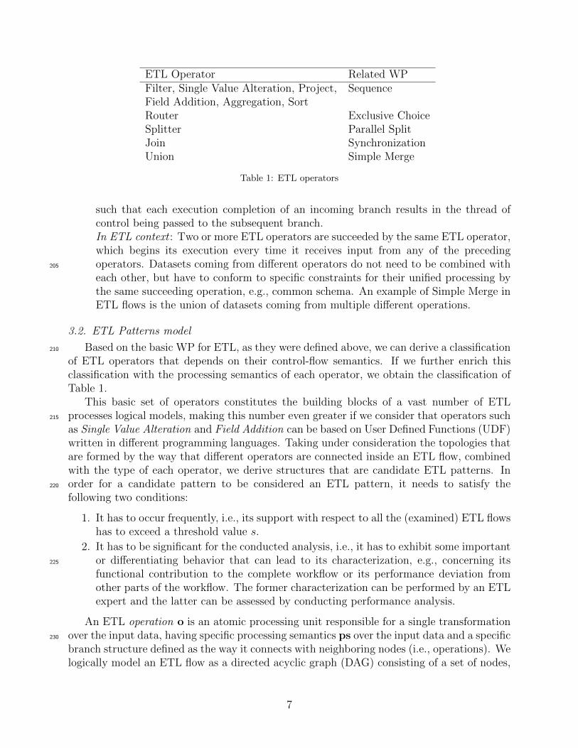
ETL Operator Related WPFilter, Single Value Alteration, Project, SequenceField Addition, Aggregation, SortRouter Exclusive ChoiceSplitter Parallel SplitJoin SynchronizationUnion Simple Merge
Table 1: ETL operators
such that each execution completion of an incoming branch results in the thread ofcontrol being passed to the subsequent branch.In ETL context : Two or more ETL operators are succeeded by the same ETL operator,which begins its execution every time it receives input from any of the precedingoperators. Datasets coming from different operators do not need to be combined with205
each other, but have to conform to specific constraints for their unified processing bythe same succeeding operation, e.g., common schema. An example of Simple Merge inETL flows is the union of datasets coming from multiple different operations.
3.2. ETL Patterns model
Based on the basic WP for ETL, as they were defined above, we can derive a classification210
of ETL operators that depends on their control-flow semantics. If we further enrich thisclassification with the processing semantics of each operator, we obtain the classification ofTable 1.
This basic set of operators constitutes the building blocks of a vast number of ETLprocesses logical models, making this number even greater if we consider that operators such215
as Single Value Alteration and Field Addition can be based on User Defined Functions (UDF)written in different programming languages. Taking under consideration the topologies thatare formed by the way that different operators are connected inside an ETL flow, combinedwith the type of each operator, we derive structures that are candidate ETL patterns. Inorder for a candidate pattern to be considered an ETL pattern, it needs to satisfy the220
following two conditions:
1. It has to occur frequently, i.e., its support with respect to all the (examined) ETL flowshas to exceed a threshold value s.
2. It has to be significant for the conducted analysis, i.e., it has to exhibit some importantor differentiating behavior that can lead to its characterization, e.g., concerning its225
functional contribution to the complete workflow or its performance deviation fromother parts of the workflow. The former characterization can be performed by an ETLexpert and the latter can be assessed by conducting performance analysis.
An ETL operation o is an atomic processing unit responsible for a single transformationover the input data, having specific processing semantics ps over the input data and a specific230
branch structure defined as the way it connects with neighboring nodes (i.e., operations). Welogically model an ETL flow as a directed acyclic graph (DAG) consisting of a set of nodes,
7
which are ETL operations (O), while the graph edges (E) represent the directed control flowamong the nodes of the graph (o1 ≺ o2). Formally:o = ps235
ETL = (O,E), such that:∀e ∈ E : ∃(o1, o2), o1 ∈ O ∧ o2 ∈ O ∧ o1 ≺ o2
This abstract definition of the ETL flow and its operations allows for the analysis of ETLsindependent of the technologies that are used for their implementation and thus enables the240
mining of ETL patterns from a large number of ETL flows that can easily map to ourmodel. Based on the characteristics of each operator o, it can be mapped to one label l froma predefined set L through the surjective function label. Formally:label : O 7→ L
A Pattern Model PM would then be a DAG where its nodes PN have a specific label l245
and a specific branch structure. Formally:pn = lPM = (PN,E), such that:∀e ∈ E : ∃(pn1, pn2), pn1 ∈ PN ∧ pn2 ∈ PN ∧ pn1 ≺ pn2
250
We assume that only coherent structures make sense for our analysis and thus patternmodels are connected graphs, i.e., graphs for which, if we ignore directionality there is a pathfrom any of their nodes to any other node in the graph. We should note here that based ondifferent analysis requirements there can be different definitions of mappings (i.e, mappingfunctions and sets of symbols), mapping one operator to one label. For instance, an operator255
can be mapped to a label, based solely on its input and output cardinality or based on itsoperation type. We have found that the latter case can produce useful results and hencethat is the analysis that we use in our work. Thus, the labels that we use for our analysisare within a set OT, where OT ⊆ L and each element ot ∈ OT refers to the operation type ofthe operation and hence can take values from the classification of ETL operators in Table 1.260
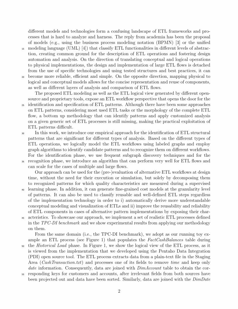
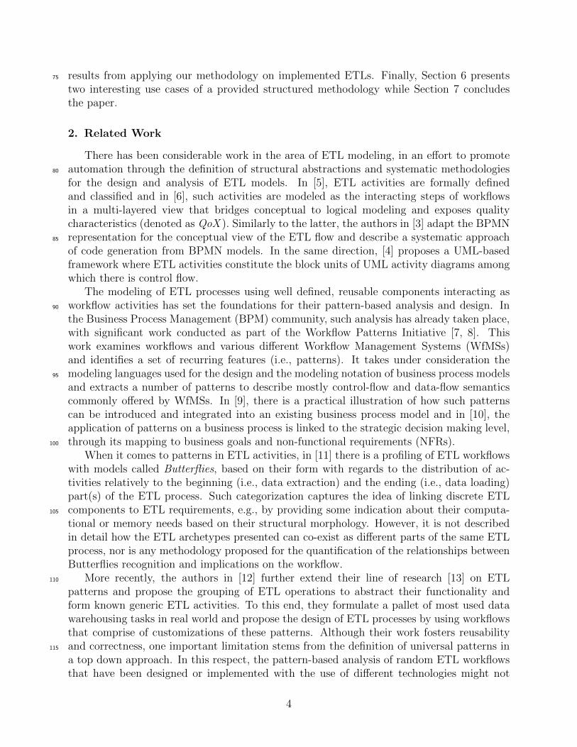
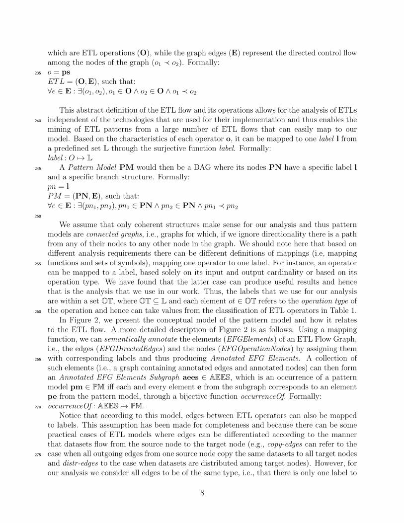
In Figure 2, we present the conceptual model of the pattern model and how it relatesto the ETL flow. A more detailed description of Figure 2 is as follows: Using a mappingfunction, we can semantically annotate the elements (EFGElements) of an ETL Flow Graph,i.e., the edges (EFGDirectedEdges) and the nodes (EFGOperationNodes) by assigning themwith corresponding labels and thus producing Annotated EFG Elements. A collection of265
such elements (i.e., a graph containing annotated edges and annotated nodes) can then forman Annotated EFG Elements Subgraph aees ∈ AEES, which is an occurrence of a patternmodel pm ∈ PM iff each and every element e from the subgraph corresponds to an elementpe from the pattern model, through a bijective function occurrenceOf. Formally:occurrenceOf : AEES 7→ PM.270
Notice that according to this model, edges between ETL operators can also be mappedto labels. This assumption has been made for completeness and because there can be somepractical cases of ETL models where edges can be differentiated according to the mannerthat datasets flow from the source node to the target node (e.g., copy-edges can refer to thecase when all outgoing edges from one source node copy the same datasets to all target nodes275
and distr-edges to the case when datasets are distributed among target nodes). However, forour analysis we consider all edges to be of the same type, i.e., that there is only one label to
8
ETLPatternsCombination
Precedence
EventualPrecedenceImmediatePrecedence
Cooccurrence Overlap Exclusivity
PatternsRepository
0..*
AtomicETLPattern
ETLPattern
ETLFlowGraph
EFGElement0..*
EFGDirectedEdge
EFGOperationNode
SemanticAnnotation
Label2..*
AnnotatedEFGElement
1
1
AnnotatedEFGElementsSubgraph
1..*
BasedOnOperationTypeAnnotation ...
sourceNode1
targetNode1
hasPatternVariation1..* combines
{ordered}
2..*PatternModelPatternElement
0..*
PatternEdgePatternNodesourceNode1
targetNode1
1
occurrenceOf
correspondsTo
correspondsTo
connection
1
Figure 2: ETL Pattern Conceptual Model
9
...
...
...Sort
SortJoin Project
Sort
SortJoin
ETL Pattern: Join
Pattern Model A
Pattern Model B
«Project» «Sort»
«Sort» «Join» «Sort»
Recognition of Pattern: JoinOccurrence of Pattern Model A
Excerpt from ETL workflow
«Aggregation»
Figure 3: Pattern Model and Pattern Occurrence on an ETL workflow
characterize all edges.As mentioned above, for our analysis we use the semantic annotation (i.e., labeling)
based on operation type (BasedOnOperationTypeAnnotation), but there can be different280
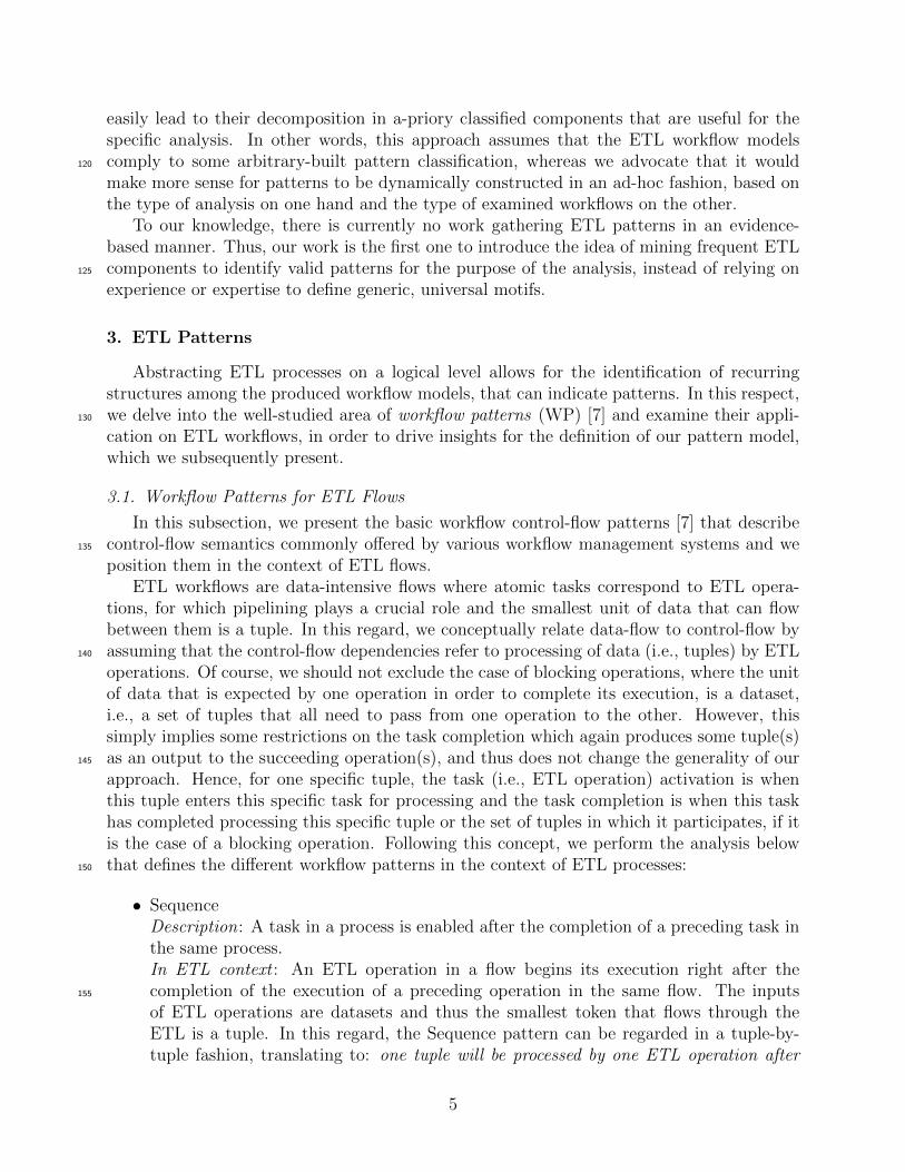
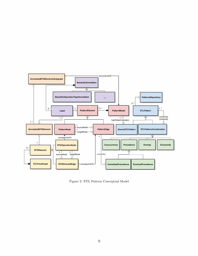
kinds of semantic annotation (i.e., subclasses of the class SemanticAnnotation), based onthe conducted analysis. As is illustrated in Figure 2, the same pattern (AtomicETLPattern)can have variations, resulting to different corresponding pattern models in Figure 3). Forinstance, two different pattern models can correspond to the same ETL functionality, so ifthe analysis purpose is the clustering of operations based on their functionality, these two285
models will constitute variations of the same pattern. An example is illustrated in Figure3), where we show how the ETL pattern Join can have two different pattern models (i.e.,Pattern Model A and Pattern Model B) and how by finding the occurrence of one of thesemodels (Pattern Model A) on the excerpt from our example ETL process from Figure 1, wecan recognize it as an instance of the ETL pattern. Furthermore, a combination of two or290
more patterns (ETLPatternsCombination) can itself be a pattern. In this respect, two (ormore) patterns can be combined in the following ways, forming a new pattern:
• Overlap: Patterns can overlap, with their pattern models sharing elements or withelements of one pattern model located inside the other. This case also includes patternnesting, where one pattern is located inside the other.295
• Precedence: One pattern is located (right) after the other.
• Cooccurrence: Both patterns occur in the same ETL flow.
• Exclusivity : Only one of the patterns can occur in the ETL flow and not the other(s).
It should be noticed that the participation of ETL patterns in ETL Pattern Combina-tions entails a concrete role for each pattern in the combination and this is denoted by the300
characterization of the combines association as ordered. Despite our approach allowing forthe occurrence of overlapping patterns and patterns one after the other (i.e., precedence),
10
a ba
cb
a
cb dsubgraphOfsubgraphOf
a
db
subgraphOf
Frequent Subgraphs
Total: 15Independent: 0
Total: 7Independent: 1
Total: 6Independent: 6
Total: 8Independent: 8
Maximal
Independent
Frequent
{a,b,c,d} Labels
Figure 4: Maximal and Independent Frequent Subgraphs
we do not consider the case of the combinations themselves being patterns (i.e., we onlyconsider Atomic ETL Patterns).
3.3. Frequent ETL Patterns305
As mentioned above, one of the conditions for a candidate pattern to be considereda pattern is that its support has to exceed some predefined value. In other words, itscorresponding pattern model(s) have to occur frequently over the entire set of examinedETL workflows. Since both the ETL workflows and the pattern models are representedusing graphs, the problem of mining such patterns can be examined under the prism of310
frequent subgraph mining, which is a subclass of frequent itemset discovery [14], where thegoal is to discover frequently occuring subgraphs within a set of graphs or a single largegraph, with frequency of occurrence above a specified threshold value.
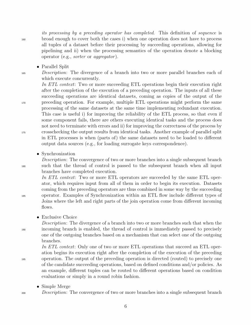
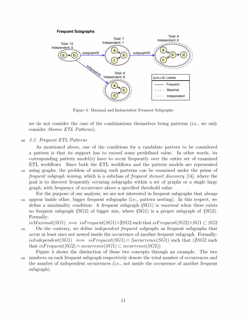
For the purpose of our analysis, we are not interested in frequent subgraphs that alwaysappear inside other, bigger frequent subgraphs (i.e., pattern nesting). In this respect, we315
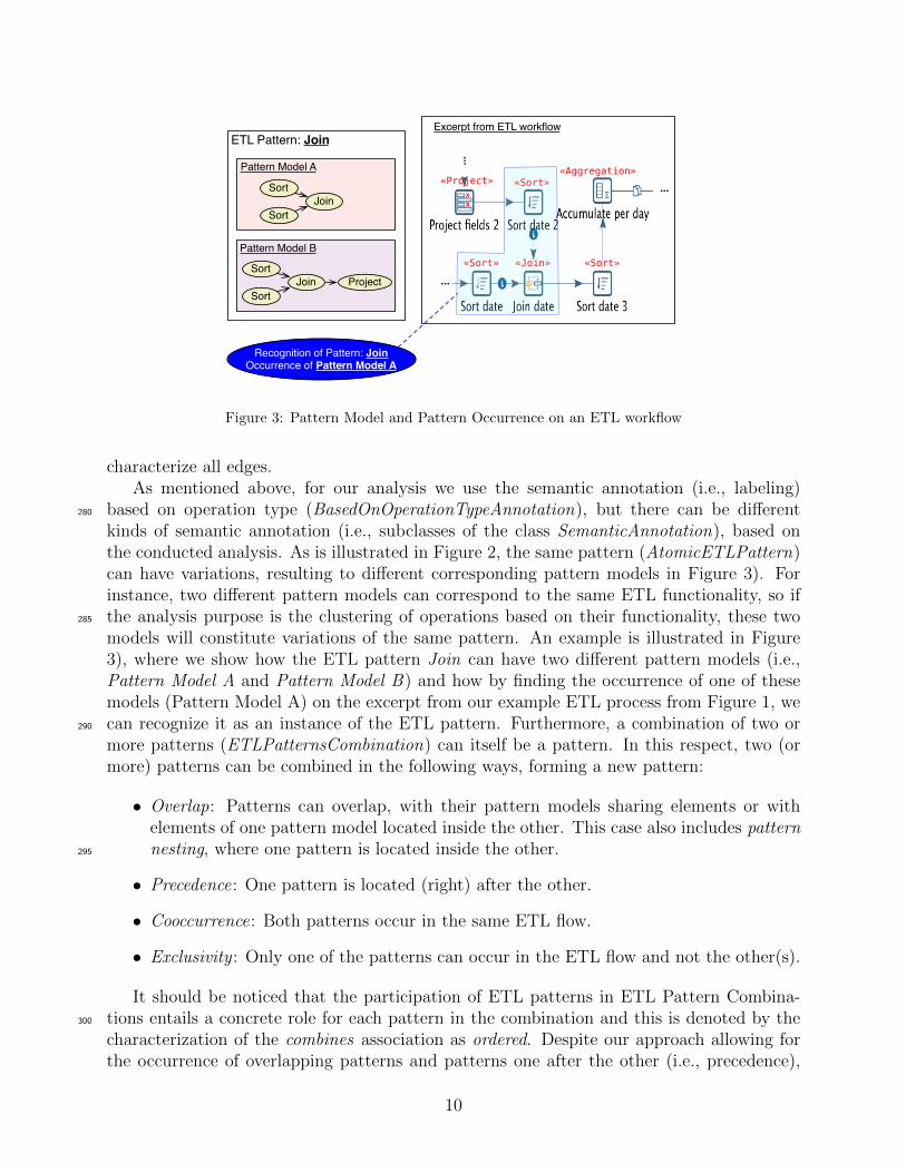
define a maximality condition: A frequent subgraph (SG1) is maximal when there existsno frequent subgraph (SG2) of bigger size, where (SG1) is a proper subgraph of (SG2).Formally:isMaximal(SG1) ⇐⇒ isFrequent(SG1)∧@SG2 such that isFrequent(SG2)∧SG1 ⊂ SG2
On the contrary, we define independent frequent subgraphs as frequent subgraphs that320
occur at least once not nested inside the occurrence of another frequent subgraph. Formally:isIndependent(SG1) ⇐⇒ isFrequent(SG1) ∧ ∃occurrence(SG1) such that (@SG2 suchthat isFrequent(SG2) ∧ occurrence(SG1) ⊂ occurrence(SG2))
Figure 4 shows the distinction of these two concepts through an example. The twonumbers on each frequent subgraph respectively denote the total number of occurrences and325
the number of independent occurrences (i.e., not inside the occurrence of another frequentsubgraph).
11
4. Architecture
In this section, we present our approach on mining ETL patterns and subsequently,recognizing instances of them on arbitrary ETL workflows. For the latter, we present our330
algorithm and we conduct an analysis regarding its complexity.
4.1. Pattern mining
The first step for mining patterns of interest is the identification of reoccurring structuresover a set of ETL workflows. As mentioned above, we can view our problem as an applicationof frequent itemset discovery, where the goal is to discover frequently occuring “items” within335
a set of “baskets”. Since we logically model ETL workflows as graphs, it is natural for thisstage to use graph mining techniques, i.e., techniques for extracting statistically significantand useful knowledge from graph structures. Given a set of graph representations of ETLworkflows, the reoccurring structures of interest are graphs, that occur as subgraphs of theinitial graphs more frequently than a specified threshold percentage. Thus, we can employ340
the use of algorithms from the well studied area of Frequent Subgraph Mining (FSM). In [18],there is a detailed review of this mature research area, including the main research challengesand the most interesting proposed solutions.
For our experiments, we decided to use the FSG algorithm [19], because of 1) its com-putational efficiency and 2) fast and reliable results from testing that we conducted using345
its available implementation. This algorithm generates candidate frequent subgraphs in abottom-up approach, starting with initial subgraphs of one edge and adding one edge ateach step while checking for the frequency criterion. It performs significant pruning to theproblem space while searching for patterns, taking advantage of the fact that if a graph isfrequent, then all of its subgraphs are also frequent.350
Two parameters can change the output of the algorithm. Firstly, the support threshold,i.e., the minimum number of ETL flows that need to contain a subgraph for it to be accountedas frequent, can vary. In addition, we can select whether we are interested only in maximalsubgraphs (see subsection 3.3).
After the identification of frequent patterns, the next step is their filtering in order to355
maintain only the patterns of some value. In this respect, a first filtering is performed bykeeping only independent subgraphs (see subsection 3.3). To this end, all the instances ofall the frequent subgraphs are recognized within the initial set of ETL workflows, using thepattern recognition algorithm defined below (subsection 4.2) and graph-subgraph relation-ships among these instances are analyzed. Subsequently, frequent subgraphs are classified360
as variations of ETL patterns, based on the conducted analysis. For instance, experts canclassify these subgraphs according to their conceptual functionality, or performance evalua-tion can be conducted to classify subgraphs based on their isolated performance as comparedto the performance of the complete ETL. The results of such analyses are then stored in arepository of ETL patterns.365
4.2. Pattern recognition
Once a knowledge base of ETL patterns has been built, occurrences of those patterns canbe recognized in any arbitrary ETL workflow. The workflow first needs to be transformed toits graph representation and then the task is reduced to finding a correspondence between the
12
a
cb
Pattern Model
root
matched node
{a,b,c,d} Labels
a
c
b a
d bb
cc
c
cd d
frontier node
Pattern Model Occurrences
c
dc
c
BFS
Annotated EFG
Figure 5: Execution of Find Pattern Model Occurrences Algorithm
model (i.e., the ETL pattern model) and part(s) of the ETL workflow graph representation.370
Since both the model and the examined ETL are modeled as graphs, this is a typical usecase for a graph matching algorithm. In [20], there is an interesting comparison betweenthe implementation in a common codebase of five state-of-the-art subgraph isomorphismalgorithms and in [21], there is a comprehensive review of different techniques that have beenproposed for this NP-complete problem, the most popular being the Ullmann’s algorithm [22]375
and the VF2 algorithm [23]. After studying these algorithms, we decided to adapt the VF2algorithm with some optimizations (Algorithm 1), maintaining different data structures whilesearching for pattern model occurrences. Our algorithm can perform very well for graphswith the cheracteristics of ETL workflows — i) very small branching factors, ii) number ofdifferent labels comparable to the average graph size.380
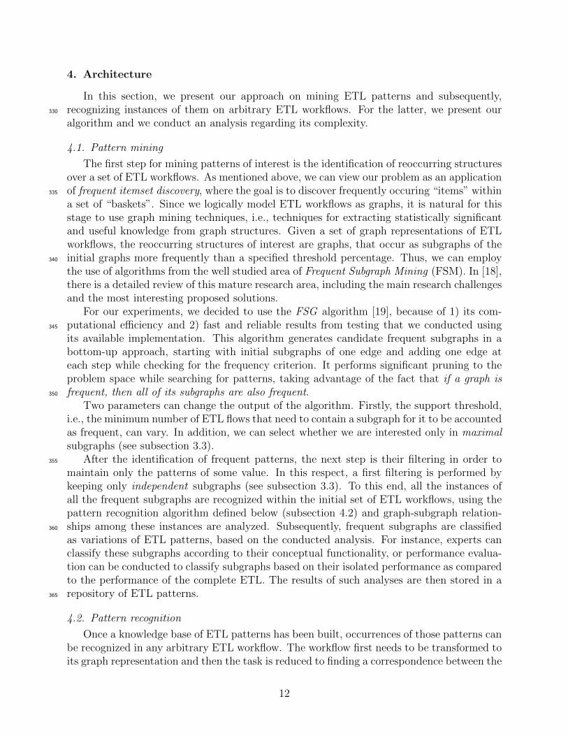
Taking under consideration the VF2 heuristic of adding to the search space only adjacentnodes while generating candidate matches, our algorithm iterates over the nodes of thepattern model in a breadth-first search (BFS) manner while at the same time matchingthem with nodes from the annotated EFG, that satisfy certain conditions (see Figure 5).The candidate node matches are searched only within adjacent (i.e., neighboring) nodes385
from the already matched nodes, which we call frontier nodes and for a specific candidatepattern match, if there is no adjacent node that satisfies the conditions, it is dismissed. Newcandidate pattern matches commence after every iteration, until the pattern model has beenfully traversed or the set of candidate pattern matches is empty.
One practical heuristic that we use to speed up the execution of the algorithm by keeping390
the number of initial candidate node matches on the annotated EFG as small as possible,is the execution of preparation steps, through which the root of the BFS, (i.e., the nodeof the pattern model from which the iteration will start) is selected to be annotated withthe label from the pattern model that is least frequently found on the annotated EFG. TheEFG is traversed once and the number of occurrences of each label is stored in count —a395
HashMap object that maps labels to integers (i.e., labels’ frequencies). One of the nodes ofthe pattern model that have the label with the minimum frequency in count, is selected as
13
the subsequent BFS starting point (i.e., the root).
Algorithm 1 Find All Pattern Model Occurrences
Input: ETL, PM, root . root is a node from the PMOutput: PO
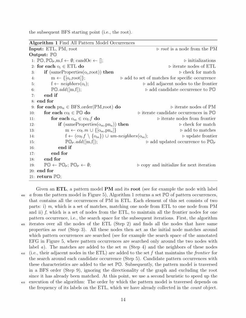
1: PO,PO2,m,f ← ∅; candOc ← []; . initializations2: for each oi ∈ ETL do . iterate nodes of ETL3: if (sameProperties(oi,root)) then . check for match4: m ← {[oi,root]}; . add to set of matches for specific occurrence5: f ← neighbors(oi); . add adjacent nodes to the frontier6: PO.add([m,f]); . add candidate occurrence to PO7: end if8: end for9: for each pnn ∈ BFS order(PM,root) do . iterate nodes of PM
10: for each col ∈ PO do . iterate candidate occurrences in PO11: for each om ∈ col.f do . iterate nodes from frontier12: if (sameProperties(om,pnn)) then . check for match13: m ← col.m ∪ {[om,pnn]} . add to matches14: f ← (col.f \ {om}) ∪ um-neighbors(om); . update frontier15: PO2.add([m,f]); . add updated occurrence to PO216: end if17: end for18: end for19: PO ← PO2; PO2 ← ∅; . copy and initialize for next iteration20: end for21: return PO;
Given an ETL, a pattern model PM and its root (see for example the node with labela from the pattern model in Figure 5), Algorithm 1 returns a set PO of pattern occurrences,400
that contains all the occurrences of PM in ETL. Each element of this set consists of twoparts: i) m, which is a set of matches, matching one node from ETL to one node from PMand ii) f, which is a set of nodes from the ETL, to maintain all the frontier nodes for onepattern occurrence, i.e., the search space for the subsequent iterations. First, the algorithmiterates over all the nodes of the ETL (Step 2) and finds all the nodes that have same405
properties as root (Step 3). All these nodes then act as the initial node matches aroundwhich pattern occurrences are searched (see for example the search space of the annotatedEFG in Figure 5, where pattern occurrences are searched only around the two nodes withlabel a). The matches are added to the set m (Step 4) and the neighbors of these nodes(i.e., their adjacent nodes in the ETL) are added to the set f that maintains the frontier for410
the search around each candidate occurrence (Step 5). Candidate pattern occurrences withthese characteristics are added to the set PO. Subsequently, the pattern model is traversedin a BFS order (Step 9), ignoring the directionality of the graph and excluding the rootsince it has already been matched. At this point, we use a second heuristic to speed up theexecution of the algorithm: The order by which the pattern model is traversed depends on415
the frequency of its labels on the ETL, which we have already collected in the count object.
14
Thus, when a pattern node has multiple unvisited neighbors (i.e., adjacent nodes that havenot yet been visited by the BFS), the order by which they are visited depends on theirlabel —from least to most frequent label in the ETL. For each candidate occurrence, eachnode from its frontier is checked for having the same properties with the current node from420
the pattern model (Step 12). If it does, then the matches and the frontier of the currentcandidate occurrence are updated (Steps 13 and 14). Regarding the frontier update, theum-neighbors, i.e., the adjacent nodes to the matched node from the ETL that have notalready been matched to a pattern node, are added to the existing nodes in the frontier andthe matched node is removed from the frontier (Step 14). Subsequently, a new candidate425
occurrence with these updated parts is added to a set PO2. In every iteration this set replacesthe old set PO that gets initialized to the empty set (Step 19). We should note that despitethe pattern model graph being traversed ignoring its directionality, when the check for sameproperties between a pattern model node and an ETL node takes place, the directionality istaken under consideration.430
4.2.1. Algorithm complexity
Although subgraph isomorphism is well-known NP-hard problem [24], in practice, ouralgorithm can execute very fast because of the particularities of ETLs and the heuristicsthat we use. The adjacent nodes for each node are maintained inside two hashmap objectsthat map labels to nodes —one hashmap for the incoming adjacent nodes and one for the435
outgoing adjacent nodes [25]. If n is the size of the ETL graph, then each of these twoobjects is of maximum size (n− 1) for each ETL node (a node cannot be adjacent to itselfand a node cannot be found in two different buckets of the hashmap because it only has onelabel), thus the space complexity of the algorithm is: 2 ∗ (n− 1) ∗ n = O(n2).
When it comes to the time complexity, due to the use of the hashmap objects, the check440
for same properties between the nodes of the pattern model and the ETL can take placein constant time t. Thus, if m is the size of the PM, the time complexity is: t ∗
∑mi=1Ni,
where Ni is the running number of candidate occurrences (i.e., the size of PO, see Step 10of Algorithm 1) during each iteration of the BFS. We should note that N1 is the number ofinitial candidate occurrences which is determined by the selection of the pattern model root445
element. The growth rate Nk+1
Nkof the solution space depends on the fanout of the nodes of
the ETL graph on one hand; and on the distribution of the different labels on the ETL nodes,on the other. In other words, the search space grows by being multiplied by the number ofneighbors of each node in the candidate occurrence frontier, which is being matched (see Step14 of Algorithm 1), but it also shrinks at the same time by pruning nodes that do not match450
the corresponding node from the PM. In the worst case of the ETL being a clique where allthe labels of the pattern model and all the labels of the ETL graph are the same one label,there will be no pruning and thus, every time a new node from the pattern model is visited,the number of candidate occurrences will multiply by (n−p) where p is the number of alreadymatched nodes, until all m nodes are visited. Thus, in the worst case the total number of455
candidate occurrences during the last iteration will be: Nm =∏m
i=1(n − i) = O( (n−1)!(n−1−m)!
).However, according to our experience with implementing ETL workflows from the TPC-DIbenchmark, this is hardly a realistic case for ETL graphs, where the branching factor is closeto 1. In addition, the existence of a number of different labels in real ETL graphs, guaranteesthat a lot of pruning takes place, especially in the common case where no (unmatched) node460
15
30
25
19 18
14 1311
75
3 2 1
36
29
18
129 8 7
31 0 0 0
37
26
15
85 4
20 0 0 0 0
27
20
11
2 1 1 0 0 0 0 0 0
17
13
5
0 0 0 0 0 0 0 0 0
85
1 0 0 0 0 0 0 0 0 01 0 0 0 0 0 0 0 0 0 0 00
5
10
15
20
25
30
35
40
20 24 28 32 36 40 44 48 52 56 60 64
Num
berofpa,
erns
support(%)
Series1
Series2
Series3
Series4
Series5
Series6
Series7
1234
567
pattern size
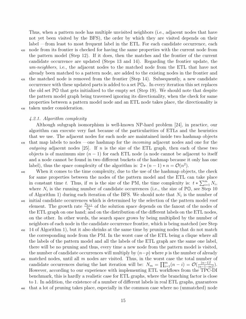
Figure 6: Number of (non-maximal) frequent patterns identified for different support values and for differentpattern sizes
of specific label is adjacent to a candidate occurrence, which can very easily be checked,with the bucket corresponding to this label being empty. Furthermore, the size m of themeaningful pattern models is usually very small (< 10).
5. Results
In this section, we show results obtained from the application of the algorithms to 25465
ETL processes from the TPC-DI benchmark2 that we implemented using the Pentaho DataIntegration open source tool3.
5.1. Mined ETL Patterns
In this subsection, we present our results from mining frequent patterns during the Learn-ing Phase of our approach. To this end, we used the FSG algorithm [19] on the graph470
representation of the 25 TPC-DI ETLs, using its available implementation4. In Figure 6, weshow the number of frequent patterns of different size (i.e., number of edges) that we obtain,using different values for support (i.e., the minimum proportion of ETL workflows that needto contain a subgraph for it to be accounted as a frequent pattern). It should be noticed thatthe FSG algorithm executed in less than 2 msec for all these cases. As expected, since we are475
not imposing the maximality constraint, as the support increases, the number of identified
2http://www.tpc.org/tpcdi/3Full implementation available at: https://github.com/AKartashoff/TPCDI-PDI/4http://glaros.dtc.umn.edu/gkhome/pafi/overview
16
0102030405060708090
100
20 24 28 32 36 40 44 48 52 56 60 64
coverage(%
)
support(%)
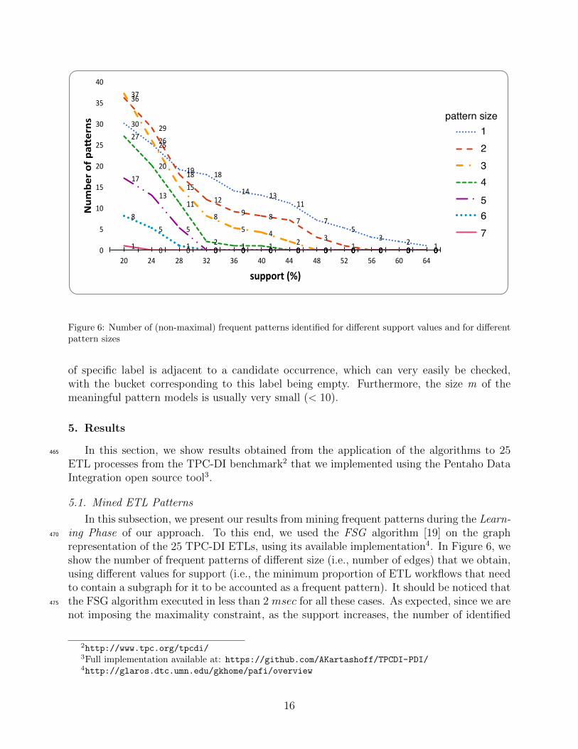
Figure 7: Coverage of ETL workflows for different support values
patterns decreases. In other words, all the patterns that are identified with some supports will also be identified with any other smaller support, plus additional patterns that donot satisfy the frequency criterion for s. We can also infer from Figure 6 that in general, asthe size of the patterns decreases, the number of identified patterns increases. However, as480
can be seen, there are some noticeable exceptions to this rule. The curve for pattern size1 crosses both with the curve for pattern size 2 and with the curve for pattern size 3. Thereason is that the same pattern of size 1 can be a subgraph of two or more patterns of size2. As an example, let us consider a set of three labels {a, b, c} and the identification of thefollowing frequent patterns of size 2: i) [a − a − b], ii) [a − b − a], iii) [a − a − c] and iv)485
[a − c − a]. Each subgraph of these four frequent patterns will also be a frequent patternfor the same support s. However, there are only three distinct subgraphs of size 1 amongthese patterns —i) [a− a], ii) [a− b] and iii) [a− c]— and it is not necessary that there existmore frequent patterns of size 1 with these labels. The same explanation can be given forthe case of the curve for pattern size 2 crossing with the curve for pattern size 3. The reason490
that the rule holds for greater s values, is that this explained behavior is outgrown by thetendency of larger patterns to be more difficult to find frequently. Finally, we can observethat beyond some support value, there is no frequent pattern identified.
In Figure 7, we show for different support values, the coverage of all the ETL workflowsfrom the patterns identified, i.e., the percentage of ETL operations that take part in pattern495
model occurrences. Pattern identification was conducted by our implementation of the al-gorithm proposed in Subsec. 4.25. As we can observe, the coverage decreases as the supportvalue increases, which is an expected behavior since the overall number of identified patternsdecreases as well (see Figure 6). This decrease appears to be non-linear and especially be-yond some value s (≈ 45%) for which coverage is ≈ 80%, it appears to decrease faster and500
faster as support increases. Another interesting observation is that for a small value of s,
5Full implementation available at: https://github.com/theovas/etl-patterns/
17
0102030405060708090100
0-25 25-50 50-75 75-100 100-125 125-150 150-175 175-200 200-300 >300
Noofpa'
erns
Noofoccurrences
Figure 8: Number of patterns w.r.t. their number of occurrences
87
138 7 5 3 0 3 0 1
29
0
10
20
30
40
50
60
70
80
90
100
0% 0-10% 10-20% 20-30% 30-40% 40-50% 50-60% 60-70% 70-80% 80-90% 90-100%
Noofpa'
erns
%independentoccurrences
Figure 9: Number of patterns w.r.t. their frequency of independent occurrences
coverage reaches a very high value, above 93%. This validates our claim that it is possibleto map, if not the complete, at least a very large part of an ETL workflow to pattern modeloccurrences, facilitating the translation to its conceptual representation, as is explained inSubsection 6.3.505
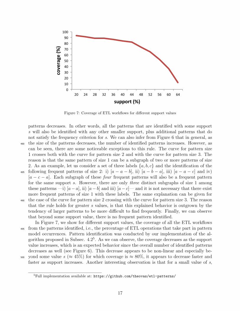
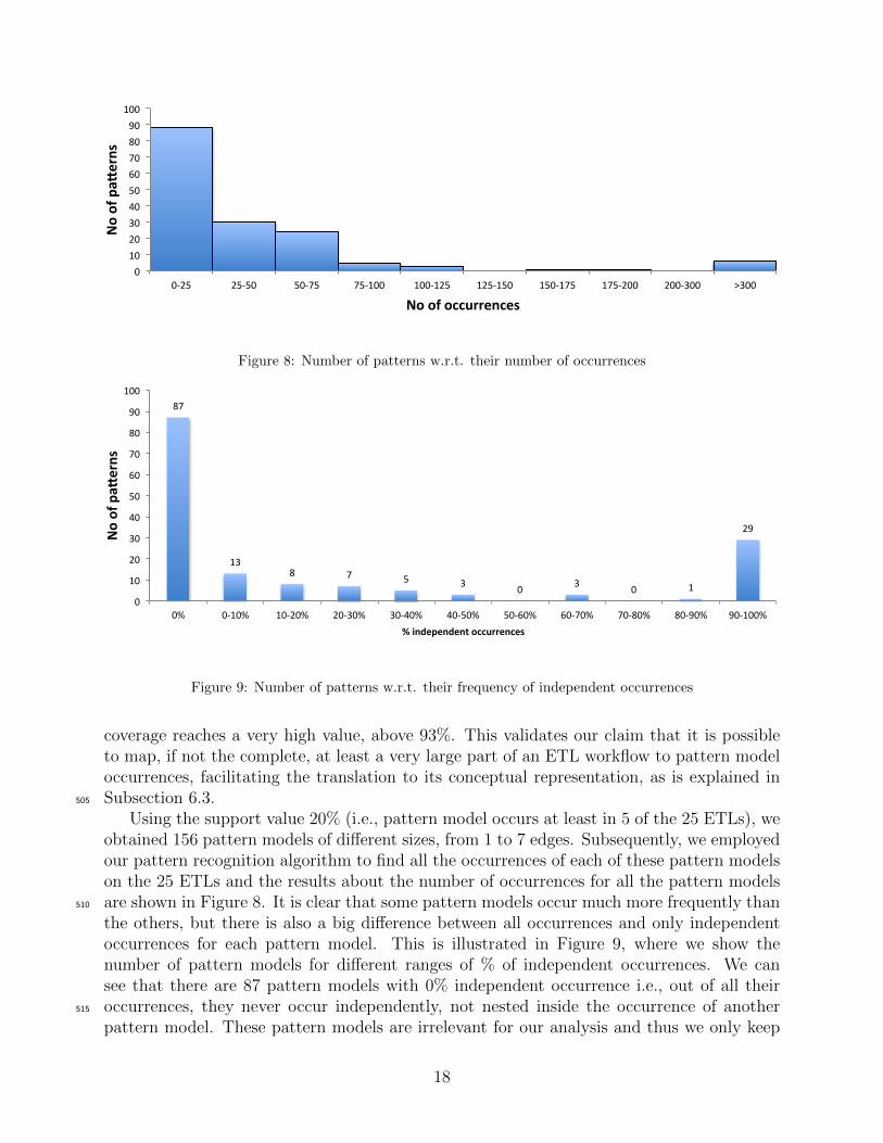
Using the support value 20% (i.e., pattern model occurs at least in 5 of the 25 ETLs), weobtained 156 pattern models of different sizes, from 1 to 7 edges. Subsequently, we employedour pattern recognition algorithm to find all the occurrences of each of these pattern modelson the 25 ETLs and the results about the number of occurrences for all the pattern modelsare shown in Figure 8. It is clear that some pattern models occur much more frequently than510
the others, but there is also a big difference between all occurrences and only independentoccurrences for each pattern model. This is illustrated in Figure 9, where we show thenumber of pattern models for different ranges of % of independent occurrences. We cansee that there are 87 pattern models with 0% independent occurrence i.e., out of all theiroccurrences, they never occur independently, not nested inside the occurrence of another515
pattern model. These pattern models are irrelevant for our analysis and thus we only keep
18
Project SortJoin
Sort
Sort
Join Sort
Double Join
Project
Filter
Router Union
Selective Processing
Project Project
Process Chain
Project...
SortJoin
TableInput
Project Sort
Lookup Operation
FileInput TableOutput
Dimension Loading
Project TableOutputSplitter
TableOutputSurrogate Key Pipeline
SortJoin Project
SortJoin
ProjectUnion Dummy
ProjectUnion
SplitterProject
Copy DatasetProject
TableInput Project
Extract from Table
Project
Load To Table
TableOutput Filter
Exclusive Choice
Router
Sequence
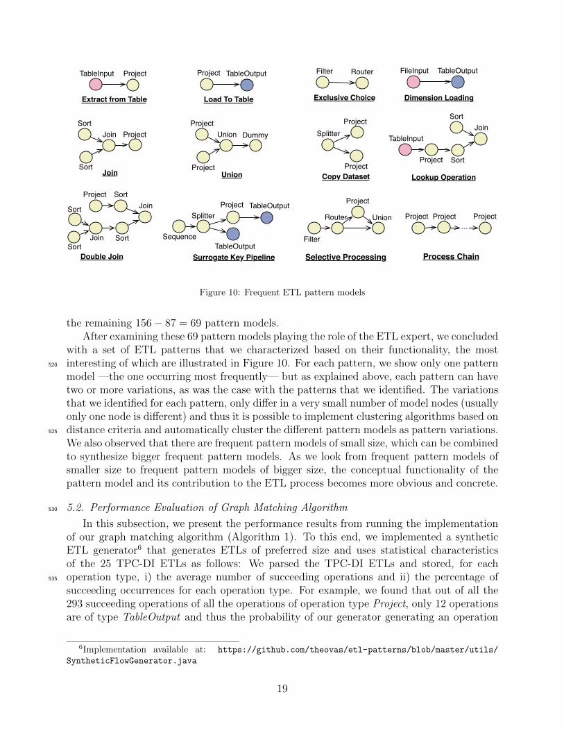
Figure 10: Frequent ETL pattern models
the remaining 156− 87 = 69 pattern models.After examining these 69 pattern models playing the role of the ETL expert, we concluded
with a set of ETL patterns that we characterized based on their functionality, the mostinteresting of which are illustrated in Figure 10. For each pattern, we show only one pattern520
model —the one occurring most frequently— but as explained above, each pattern can havetwo or more variations, as was the case with the patterns that we identified. The variationsthat we identified for each pattern, only differ in a very small number of model nodes (usuallyonly one node is different) and thus it is possible to implement clustering algorithms based ondistance criteria and automatically cluster the different pattern models as pattern variations.525
We also observed that there are frequent pattern models of small size, which can be combinedto synthesize bigger frequent pattern models. As we look from frequent pattern models ofsmaller size to frequent pattern models of bigger size, the conceptual functionality of thepattern model and its contribution to the ETL process becomes more obvious and concrete.
5.2. Performance Evaluation of Graph Matching Algorithm530
In this subsection, we present the performance results from running the implementationof our graph matching algorithm (Algorithm 1). To this end, we implemented a syntheticETL generator6 that generates ETLs of preferred size and uses statistical characteristicsof the 25 TPC-DI ETLs as follows: We parsed the TPC-DI ETLs and stored, for eachoperation type, i) the average number of succeeding operations and ii) the percentage of535
succeeding occurrences for each operation type. For example, we found that out of all the293 succeeding operations of all the operations of operation type Project, only 12 operationsare of type TableOutput and thus the probability of our generator generating an operation
6Implementation available at: https://github.com/theovas/etl-patterns/blob/master/utils/
SyntheticFlowGenerator.java
19
0
0.5
1
1.5
2
2.5
3
3.5
4
4.5
5
10 100 1000 10000 100000
processing+me
(msec)
graphsize
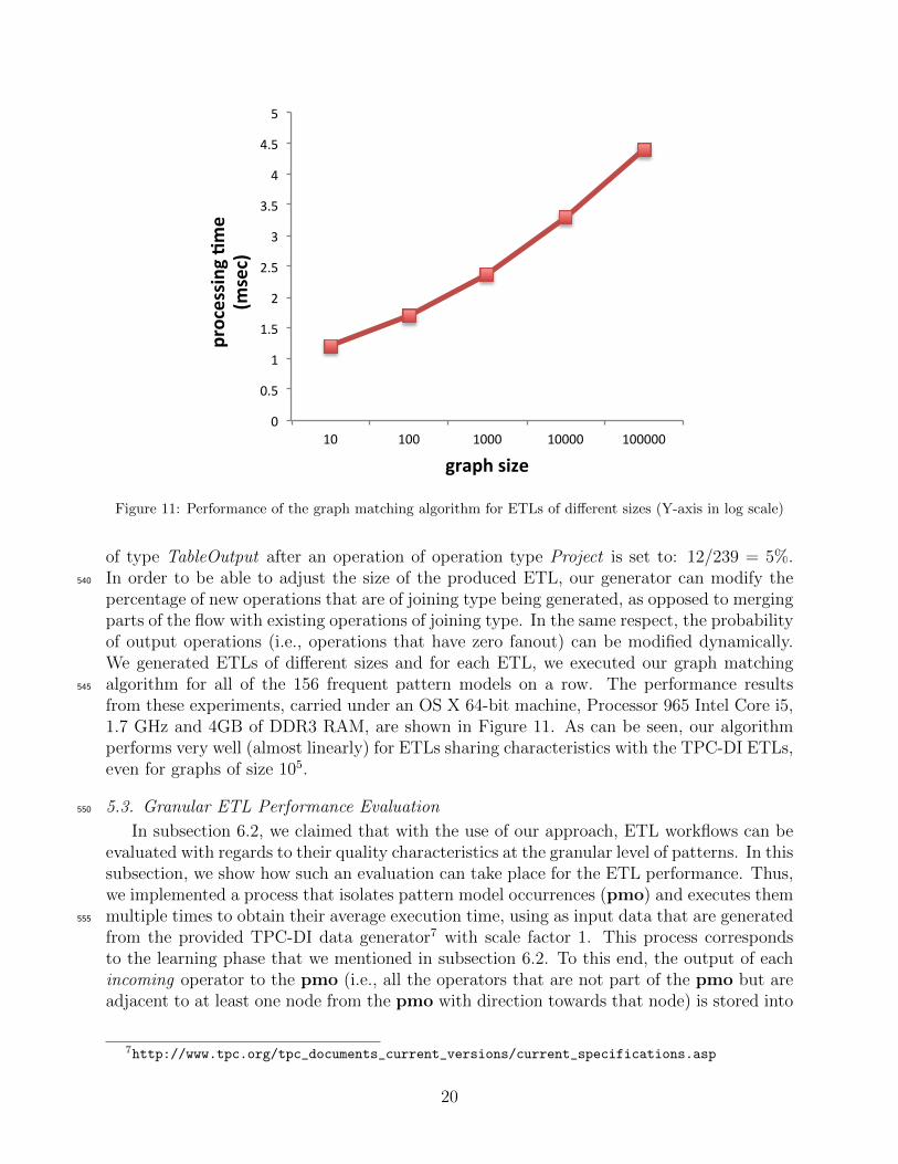
Figure 11: Performance of the graph matching algorithm for ETLs of different sizes (Y-axis in log scale)
of type TableOutput after an operation of operation type Project is set to: 12/239 = 5%.In order to be able to adjust the size of the produced ETL, our generator can modify the540
percentage of new operations that are of joining type being generated, as opposed to mergingparts of the flow with existing operations of joining type. In the same respect, the probabilityof output operations (i.e., operations that have zero fanout) can be modified dynamically.We generated ETLs of different sizes and for each ETL, we executed our graph matchingalgorithm for all of the 156 frequent pattern models on a row. The performance results545
from these experiments, carried under an OS X 64-bit machine, Processor 965 Intel Core i5,1.7 GHz and 4GB of DDR3 RAM, are shown in Figure 11. As can be seen, our algorithmperforms very well (almost linearly) for ETLs sharing characteristics with the TPC-DI ETLs,even for graphs of size 105.
5.3. Granular ETL Performance Evaluation550
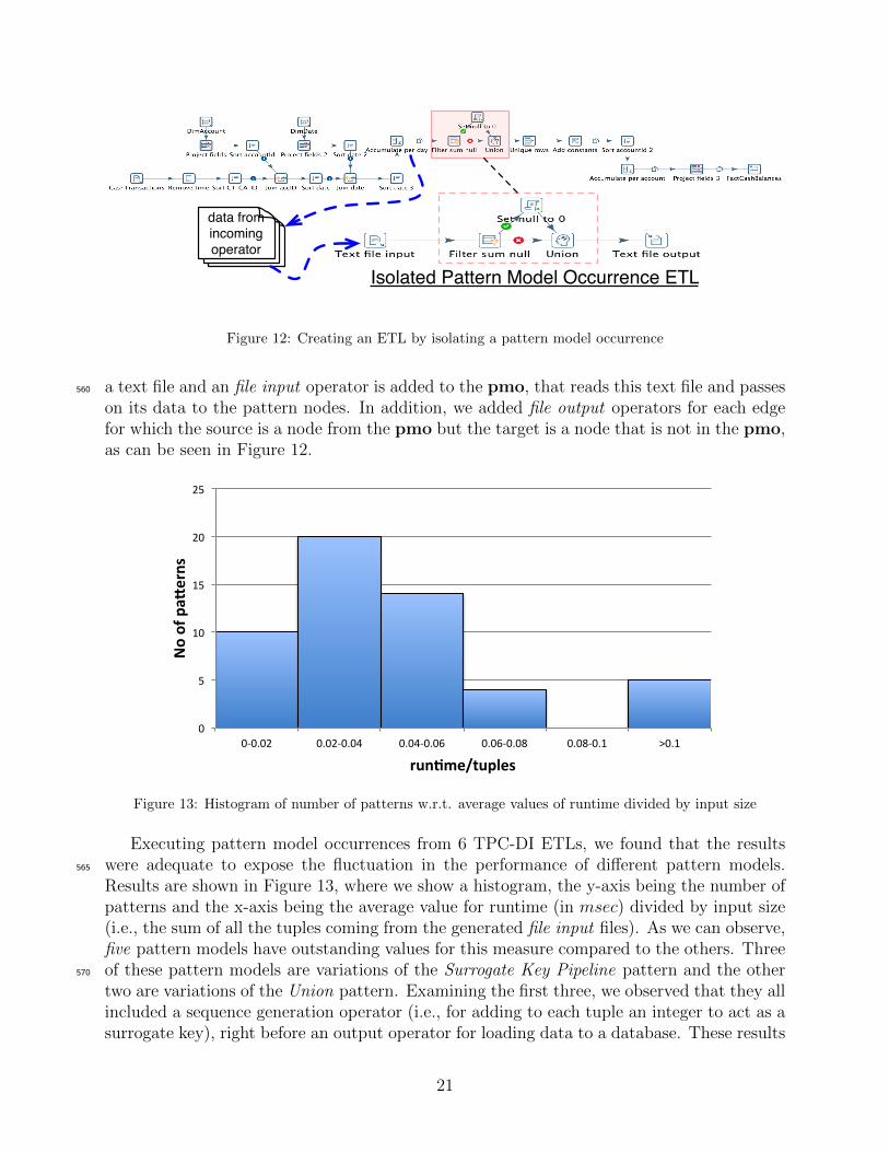
In subsection 6.2, we claimed that with the use of our approach, ETL workflows can beevaluated with regards to their quality characteristics at the granular level of patterns. In thissubsection, we show how such an evaluation can take place for the ETL performance. Thus,we implemented a process that isolates pattern model occurrences (pmo) and executes themmultiple times to obtain their average execution time, using as input data that are generated555
from the provided TPC-DI data generator7 with scale factor 1. This process correspondsto the learning phase that we mentioned in subsection 6.2. To this end, the output of eachincoming operator to the pmo (i.e., all the operators that are not part of the pmo but areadjacent to at least one node from the pmo with direction towards that node) is stored into
7http://www.tpc.org/tpc_documents_current_versions/current_specifications.asp
20
Isolated Pattern Model Occurrence ETL
data from incoming operator
Figure 12: Creating an ETL by isolating a pattern model occurrence
a text file and an file input operator is added to the pmo, that reads this text file and passes560
on its data to the pattern nodes. In addition, we added file output operators for each edgefor which the source is a node from the pmo but the target is a node that is not in the pmo,as can be seen in Figure 12.
0
5
10
15
20
25
0-0.02 0.02-0.04 0.04-0.06 0.06-0.08 0.08-0.1 >0.1
Noofpa'
erns
run-me/tuples
Figure 13: Histogram of number of patterns w.r.t. average values of runtime divided by input size
Executing pattern model occurrences from 6 TPC-DI ETLs, we found that the resultswere adequate to expose the fluctuation in the performance of different pattern models.565
Results are shown in Figure 13, where we show a histogram, the y-axis being the number ofpatterns and the x-axis being the average value for runtime (in msec) divided by input size(i.e., the sum of all the tuples coming from the generated file input files). As we can observe,five pattern models have outstanding values for this measure compared to the others. Threeof these pattern models are variations of the Surrogate Key Pipeline pattern and the other570
two are variations of the Union pattern. Examining the first three, we observed that they allincluded a sequence generation operator (i.e., for adding to each tuple an integer to act as asurrogate key), right before an output operator for loading data to a database. These results
21
Prepare ETL training flows
Apply Techniques to mine potential
patternsDefine and Classify
Patterns
Learning PhaseTranslate to data
model and store in patterns repository
Prepare ETL flow
Run recognition algorithm using
Models from Repository
Select pattern matching strategy
Recognition Phase
Translate to pattern-based model
Patterns Repository
Figure 14: Process Architecture of ETL Workflow Patterns Analysis
are a clear indication of an anti-pattern, since with this design data cannot be processedin a parallel fashion and can possibly be resolved by pushing back the sequence generation575
operator earlier in the flow.
6. ETL Patterns Use Cases
The identification of patterns within ETL processes and their definition and classificationcan be used in various ETL projects with contributions spanning from more efficient ETLquality analysis to more usable and reusable ETL models. In this section, we first present a580
structured methodology according to which our approach can be utilized in context of ETLdesign. Subsequently, we present two use cases that expose the value of using ETL flowspatterns that are derived from our data-driven approach.
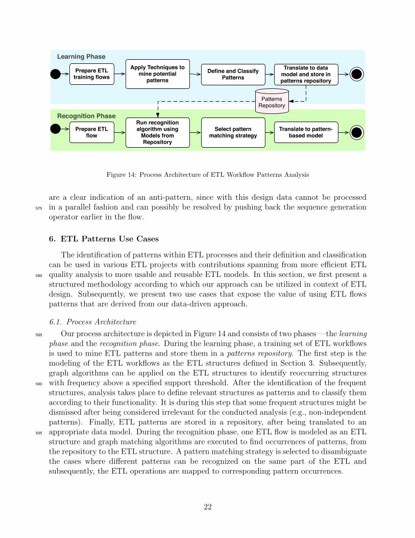
6.1. Process Architecture
Our process architecture is depicted in Figure 14 and consists of two phases —the learning585
phase and the recognition phase. During the learning phase, a training set of ETL workflowsis used to mine ETL patterns and store them in a patterns repository. The first step is themodeling of the ETL workflows as the ETL structures defined in Section 3. Subsequently,graph algorithms can be applied on the ETL structures to identify reoccurring structureswith frequency above a specified support threshold. After the identification of the frequent590
structures, analysis takes place to define relevant structures as patterns and to classify themaccording to their functionality. It is during this step that some frequent structures might bedismissed after being considered irrelevant for the conducted analysis (e.g., non-independentpatterns). Finally, ETL patterns are stored in a repository, after being translated to anappropriate data model. During the recognition phase, one ETL flow is modeled as an ETL595
structure and graph matching algorithms are executed to find occurrences of patterns, fromthe repository to the ETL structure. A pattern matching strategy is selected to disambiguatethe cases where different patterns can be recognized on the same part of the ETL andsubsequently, the ETL operations are mapped to corresponding pattern occurrences.
22
0,0000,2000,4000,6000,8001,0001,2001,4001,600
ini+al
random
op_exec_+me
op_exec_+me/inp_size
pa:ern_exec_+me/inp_size
Run+
me(sec)
ThreadsAlloca+onCriterion
Ini+al +10instances
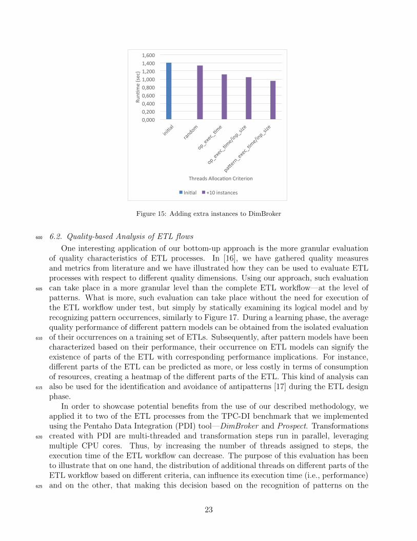
Figure 15: Adding extra instances to DimBroker
6.2. Quality-based Analysis of ETL flows600
One interesting application of our bottom-up approach is the more granular evaluationof quality characteristics of ETL processes. In [16], we have gathered quality measuresand metrics from literature and we have illustrated how they can be used to evaluate ETLprocesses with respect to different quality dimensions. Using our approach, such evaluationcan take place in a more granular level than the complete ETL workflow—at the level of605
patterns. What is more, such evaluation can take place without the need for execution ofthe ETL workflow under test, but simply by statically examining its logical model and byrecognizing pattern occurrences, similarly to Figure 17. During a learning phase, the averagequality performance of different pattern models can be obtained from the isolated evaluationof their occurrences on a training set of ETLs. Subsequently, after pattern models have been610
characterized based on their performance, their occurrence on ETL models can signify theexistence of parts of the ETL with corresponding performance implications. For instance,different parts of the ETL can be predicted as more, or less costly in terms of consumptionof resources, creating a heatmap of the different parts of the ETL. This kind of analysis canalso be used for the identification and avoidance of antipatterns [17] during the ETL design615
phase.In order to showcase potential benefits from the use of our described methodology, we
applied it to two of the ETL processes from the TPC-DI benchmark that we implementedusing the Pentaho Data Integration (PDI) tool—DimBroker and Prospect. Transformationscreated with PDI are multi-threaded and transformation steps run in parallel, leveraging620
multiple CPU cores. Thus, by increasing the number of threads assigned to steps, theexecution time of the ETL workflow can decrease. The purpose of this evaluation has beento illustrate that on one hand, the distribution of additional threads on different parts of theETL workflow based on different criteria, can influence its execution time (i.e., performance)and on the other, that making this decision based on the recognition of patterns on the625
23
0
2
4
6
8
10
12
14
ini*al
random
op_exec_*me
op_exec_*me/inp_size
pa9ern_exec_*me/inp_size
Run*
me(sec)
ThreadsAlloca*onCriterion
Ini*al +10instances
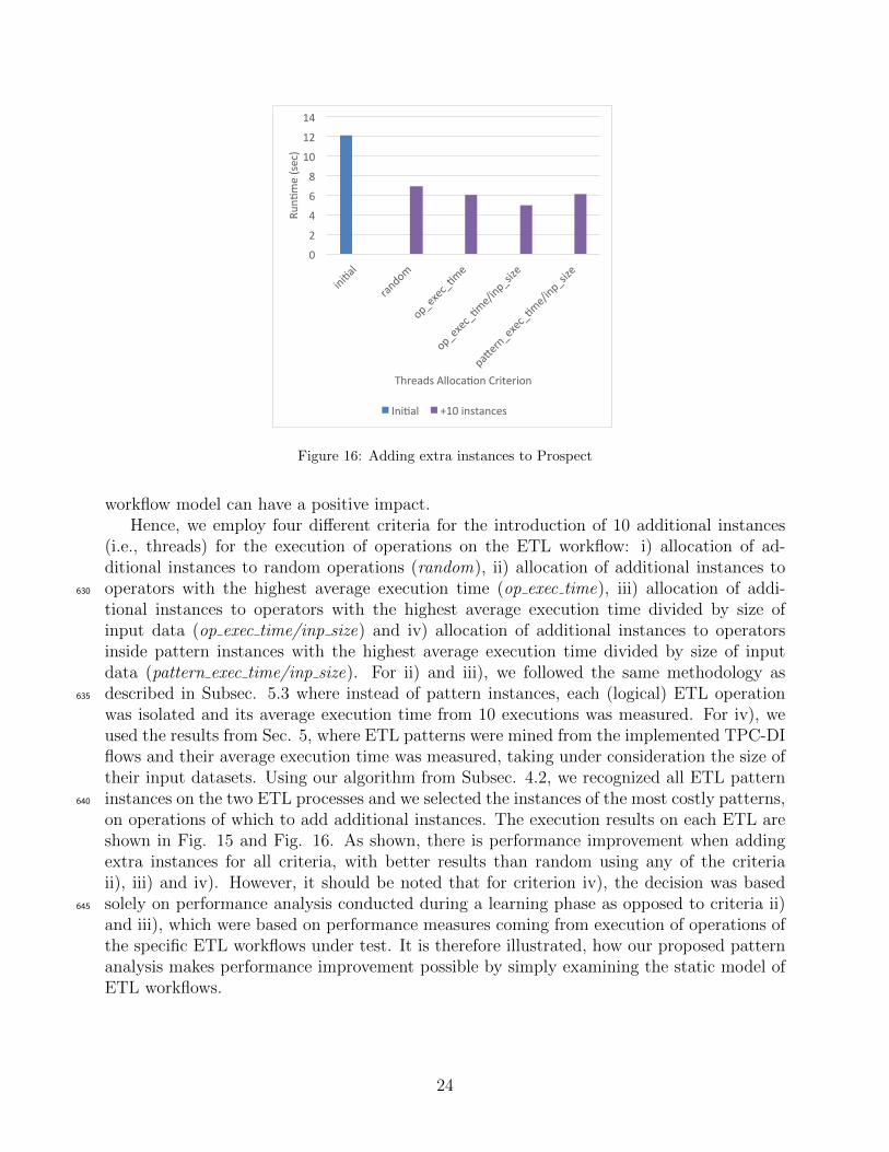
Figure 16: Adding extra instances to Prospect
workflow model can have a positive impact.Hence, we employ four different criteria for the introduction of 10 additional instances
(i.e., threads) for the execution of operations on the ETL workflow: i) allocation of ad-ditional instances to random operations (random), ii) allocation of additional instances tooperators with the highest average execution time (op exec time), iii) allocation of addi-630
tional instances to operators with the highest average execution time divided by size ofinput data (op exec time/inp size) and iv) allocation of additional instances to operatorsinside pattern instances with the highest average execution time divided by size of inputdata (pattern exec time/inp size). For ii) and iii), we followed the same methodology asdescribed in Subsec. 5.3 where instead of pattern instances, each (logical) ETL operation635
was isolated and its average execution time from 10 executions was measured. For iv), weused the results from Sec. 5, where ETL patterns were mined from the implemented TPC-DIflows and their average execution time was measured, taking under consideration the size oftheir input datasets. Using our algorithm from Subsec. 4.2, we recognized all ETL patterninstances on the two ETL processes and we selected the instances of the most costly patterns,640
on operations of which to add additional instances. The execution results on each ETL areshown in Fig. 15 and Fig. 16. As shown, there is performance improvement when addingextra instances for all criteria, with better results than random using any of the criteriaii), iii) and iv). However, it should be noted that for criterion iv), the decision was basedsolely on performance analysis conducted during a learning phase as opposed to criteria ii)645
and iii), which were based on performance measures coming from execution of operations ofthe specific ETL workflows under test. It is therefore illustrated, how our proposed patternanalysis makes performance improvement possible by simply examining the static model ofETL workflows.
24
{CT_CA_ID=
accountid}
{datevalue=date}
{group by: date}
{if: CT_AMT_sum is NULL}
{group by: sk_account_id}
TPC-DI use case
Extractfrom File
CashTransactions.txt
LookupOperation
DimAccount
LookupOperation
DimDate
Accumulate SelectiveProcessing
ProcessChain Accumulate Load To
Table
FactCashBalances
Logical Model
Conceptual Model
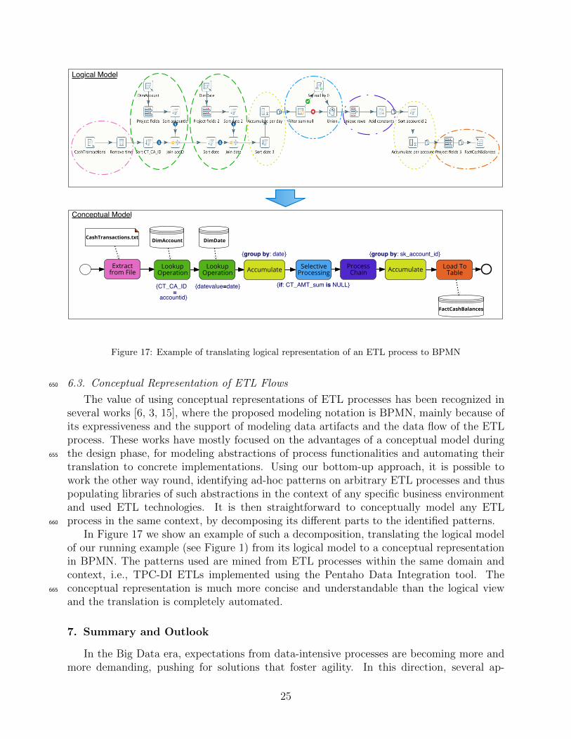
Figure 17: Example of translating logical representation of an ETL process to BPMN
6.3. Conceptual Representation of ETL Flows650
The value of using conceptual representations of ETL processes has been recognized inseveral works [6, 3, 15], where the proposed modeling notation is BPMN, mainly because ofits expressiveness and the support of modeling data artifacts and the data flow of the ETLprocess. These works have mostly focused on the advantages of a conceptual model duringthe design phase, for modeling abstractions of process functionalities and automating their655
translation to concrete implementations. Using our bottom-up approach, it is possible towork the other way round, identifying ad-hoc patterns on arbitrary ETL processes and thuspopulating libraries of such abstractions in the context of any specific business environmentand used ETL technologies. It is then straightforward to conceptually model any ETLprocess in the same context, by decomposing its different parts to the identified patterns.660
In Figure 17 we show an example of such a decomposition, translating the logical modelof our running example (see Figure 1) from its logical model to a conceptual representationin BPMN. The patterns used are mined from ETL processes within the same domain andcontext, i.e., TPC-DI ETLs implemented using the Pentaho Data Integration tool. Theconceptual representation is much more concise and understandable than the logical view665
and the translation is completely automated.
7. Summary and Outlook
In the Big Data era, expectations from data-intensive processes are becoming more andmore demanding, pushing for solutions that foster agility. In this direction, several ap-
25
proaches have been proposed for the effective modeling of ETL processes, raising the con-670
ceptual level of ETL activities and focusing on the reuse of commonly occurring componentsduring ETL design. However, the frameworks introduced so far heavily rely on expertise todefine some universal abstractions that attempt to be applicable for the analysis of arbitraryETL workflows. In this paper, we introduced a novel empirical approach for pattern-basedanalysis of ETL workflows in a bottom-up manner. We formally defined an ETL pattern675
model and we illustrated how it can be instantiated using a training set of ETL workflowsto extract frequently reoccurring structural motifs. The graph representation that we adoptenables the use of graph algorithms, such as frequent subgraph discovery algorithms for themining phase and graph matching algorithms for the recognition phase. For the latter, weadapted the VF2 algorithm with some optimizations and we showed through experiments680
how it performs very well for ETL workflows. In addition, we presented the most frequentETL patterns that we identified in implemented processes from the TPC-DI framework, aswell as the results from different configurations of the used algorithms. Results show highefficiency and effectiveness of our approach and future work can delve deeper into the eval-uation and pattern-based benchmarking of a larger number of realistic ETL workflows to685
build a solid Knowledge Base of ETL patterns and their characteristics.
Acknowledgements. This research has been funded by the European Commissionthrough the Erasmus Mundus Joint Doctorate “Information Technologies for Business Intel-ligence - Doctoral College” (IT4BI-DC).690
References
[1] M. A. Beyer, E. Thoo, E. Zaidi, R. Greenwald, Magic quadrant for data integrationtools, Tech. rep., Gartner (August 2016).
[2] A. Abello, J. Darmont, L. Etcheverry, M. Golfarelli, J. Mazon, F. Naumann, T. B.Pedersen, S. Rizzi, J. Trujillo, P. Vassiliadis, G. Vossen, Fusion cubes: Towards self-695
service business intelligence, IJDWM 9 (2) (2013) 66–88.
[3] J.-N. Mazon, E. Zimanyi, Z. El Akkaoui, J. Trujillo, A BPMN-based design and main-tenance framework for ETL processes, Int. J. Data Warehous. Min. 9 (3) (2013) 46–72.
[4] L. Munoz, J.-N. Mazon, J. Pardillo, J. Trujillo, Modelling ETL processes of data ware-houses with uml activity diagrams, in: OTM 2008, Springer Berlin Heidelberg, 2008,700
pp. 44–53.
[5] P. Vassiliadis, A. Simitsis, S. Skiadopoulos, Conceptual modeling for ETL processes,DOLAP ’02, 2002, pp. 14–21.
[6] K. Wilkinson, A. Simitsis, M. Castellanos, U. Dayal, Leveraging business process modelsfor ETL design, in: ER 2010, 2010, pp. 15–30.705
[7] W. M. P. Van Der Aalst, A. H. M. Ter Hofstede, B. Kiepuszewski, A. P. Barros, Work-flow patterns, Distrib. Parallel Databases 14 (1) (2003) 5–51.
26
[8] N. Russell, A. H. M. ter Hofstede, D. Edmond, W. M. P. van der Aalst, Workflow DataPatterns: Identification, Representation and Tool Support, Springer Berlin Heidelberg,Berlin, Heidelberg, 2005, pp. 353–368.710
[9] T. Gschwind, J. Koehler, J. Wong, Applying Patterns during Business Process Model-ing, Springer Berlin Heidelberg, 2008, pp. 4–19.
[10] G. Mussbacher, D. Amyot, S. A. Behnam, Towards a pattern-based framework for goal-driven business process modeling, SERA 2010 (2010) 137–145.
[11] A. Simitsis, P. Vassiliadis, U. Dayal, A. Karagiannis, V. Tziovara, Benchmarking ETL715
workflows, in: TPCTC 2009, 2009.
[12] B. Oliveira, O. Belo, Task clustering on ETL systems - a pattern-oriented approach, in:DATA 2015, 2015, pp. 207–214.
[13] B. Oliveira, O. Belo, A. Cuzzocrea, A pattern-oriented approach for supporting ETLconceptual modelling and its yawl-based implementation, in: DATA 2014, Vienna, Aus-720
tria, 29-31 August, 2014, 2014, pp. 408–415.
[14] M. Salmenkivi, Frequent Itemset Discovery, Springer US, Boston, MA, 2008, pp. 322–323.
[15] B. Oliveira, O. Belo, BPMN patterns for ETL conceptual modelling and validation, in:ISMIS 2012, Springer Berlin Heidelberg, 2012, pp. 445–454.725
[16] V. Theodorou, A. Abello, W. Lehner, M. Thiele, Quality measures for ETL processes:from goals to implementation, Concurrency and Computation: Practice and Experience28 (15) (2016) 3969–3993.
[17] C. U. Smith, L. G. Williams, Software performance antipatterns, WOSP ’00, ACM,New York, NY, USA, 2000, pp. 127–136.730
[18] C. Jiang, F. Coenen, M. Zito, A survey of frequent subgraph mining algorithms, Knowl-edge Eng. Review 28 (1) (2013) 75–105.
[19] M. Kuramochi, G. Karypis, Frequent subgraph discovery, ICDM ’01, Washington, DC,USA, 2001, pp. 313–320.
[20] J. Lee, W.-S. Han, R. Kasperovics, J.-H. Lee, An in-depth comparison of subgraph735
isomorphism algorithms in graph databases, Proc. VLDB Endow. 6 (2) (2012) 133–144.
[21] D. Conte, P. Foggia, C. Sansone, M. Vento, Thirty years of graph matching in pat-tern recognition, International Journal of Pattern Recognition and Artificial Intelligence18 (03) (2004) 265–298.
[22] J. R. Ullmann, An algorithm for subgraph isomorphism, J. ACM 23 (1) (1976) 31–42.740
27
[23] L. P. Cordella, P. Foggia, C. Sansone, M. Vento, An improved algorithm for matchinglarge graphs, in: In: 3rd IAPR-TC15 Workshop on Graph-based Representations inPattern Recognition, Cuen, 2001, pp. 149–159.
[24] R. Shamir, D. Tsur, Faster subtree isomorphism, in: Theory of Computing and Systems,Proc. of the Fifth Israeli Symposium on, 1997, pp. 126–131.745
[25] S. Sakr, E. Pardede, Graph Data Management: Techniques and Applications, 1st Edi-tion, IGI Publishing, Hershey, PA, 2011.
28