Embed Size (px)
Citation preview

FDA700 Rev160509
1
FROG-D 3PFREQUENCY READOUT OF GENERATOR
THREE PHASEGENERATOR DISPLAY
MODELS: FDA700 for Delta Winding FDA710 for Star Winding
Document Number:XE-FDA7PM-R0A
FIRE RESEARCH CORPORATIONwww.fireresearch.com
26 Southern Blvd., Nesconset, NY 11767TEL 631.724.8888 FAX 631.360.9727 TOLL FREE 1.800.645.0074

FDA700 Rev160509
2
CONTENTSTable of Contents
CONTENTS ................................................................................................................ 2INTRODUCTION ...................................................................................................... 3
Overview ................................................................................................................ 3Features .................................................................................................................. 3Specifications ......................................................................................................... 3
GENERAL DESCRIPTION ....................................................................................... 4Components ........................................................................................................... 4Controls and Indicators .......................................................................................... 5
INSTALLATION ........................................................................................................ 6Install Display Module........................................................................................... 6Install Signal Interface Module.............................................................................. 6Install Current Sensor ............................................................................................ 8Install Voltage Transformer .................................................................................... 8Install Optional Temperature Sensor ..................................................................... 8Install Optional Buzzer .......................................................................................... 8
OPERATION ............................................................................................................ 10WIRING .................................................................................................................... 12
Connectors and Cables......................................................................................... 12Voltage Transformers ........................................................................................... 14Current Sensors .................................................................................................... 15Star Winding Connections ................................................................................... 16Delta Winding Connections ................................................................................. 17
List of Figures/Table
Figure 1. Controls and Indicators ............................................................................... 5Figure 2. Display Module Mounting Dimensions ..................................................... 7Figure 3. Signal Interface Module Mounting Dimensions ........................................ 7Figure 4. Current Sensor ............................................................................................ 9Figure 5. Voltage Transformer ................................................................................... 9Table 1. Line Displays ............................................................................................. 11Figure 6. Display Module Wiring ............................................................................ 12Figure 7. Signal Interface Module Wiring .............................................................. 13Figure 8. Voltage Transformer Wiring ..................................................................... 14Figure 9. Current Sensor Wiring .............................................................................. 15Figure 10. Star Winding Connections ...................................................................... 16Figure 11. Delta Winding Connections .................................................................... 17

FDA700 Rev160509
3
INTRODUCTION
OverviewThe three phase generator output display panel is rated for 50/60 Hz generators
from 10 to 135 kW with delta or star windings.The display module has ultra-brite LEDs that show the generator frequency,
voltage, and current. When the generator is off line the display shows total accumulated generator hours.
The signal interface module is mounted close to the current sensors and voltage transformers so that cable runs are short. Current and voltage information is passed to the display module over a two wire datalink.
Built in safety features include voltage fluctuation, current overload and high temperature warnings.
FeaturesGenerator Hourmeter
Audible Alarm Buzzer (Optional)
Temperature Sensor (Optional)
SpecificationsDisplay Module
Dimensions: 4 1/4" Wide by 4 1/4" High
Control Box
Supply Power: 12 VDC
Supply Current: 1.25 Amps
Dimensions: 5 7/8" by 3 3/4" by 1 7/8"
Current Sensor
Winding Ratio: 150 : 5
Voltage Transformer
Input: 120/240 VAC
Output: 12/24 VAC @ 0.2A

FDA700 Rev160509
4
GENERAL DESCRIPTIONComponents
The three phase generator display consist of the following components:
Display Module
Signal Interface Module
Three (3) Current Sensors
Three (3) Voltage Transformers
Temperature Sensor (Optional)
Audible Alarm Buzzer (Optional)
Cables
Display Module
The display module is waterproof and can be mounted anywhere on the electrical panel. The display module has a square flange with overall dimensions of 4 1/4" by 4 1/4". A cutout hole of 3 3/4" in diameter is required.
Signal Interface Module
The signal interface module is waterproof with overall dimensions of 5 7/8" by 3 3/4" by 1 7/8". Clearance for the cables is required. This module is mounted close to the current sensors and voltage transformers so the cable runs are short. Current and voltage information is passed to the display module over a two wire datalink.
Current Sensor
The current sensors are used to measure current flow through a wire by electromagnetic induction. Each phase wire to the main circuit breaker is run through a current sensor opening (hole); one wire through each current sensor.
Voltage Transformer
The voltage transformers supplied work with 120 or 240 volt AC systems. The transformers should be securely mounted inside the electrical box.
Temperature Sensor (Optional)
The optional temperature sensor is installed as required.
Audible Alarm Buzzer (Optional)
The optional buzzer is installed as required.
Cables
Refer to the Wiring Section.

FDA700 Rev160509
5
Controls and IndicatorsThere is a STATUS LED located on the control box. All other controls and
indicators are located on the front of the display module.
FREQUENCY Hz Display
Shows generator frequency in hertz.
LINE Displays
Shows a number that corresponds to a line in the chart to the left of the display.
VAC VOLTAGE Display
Shows the generator output in volts of the selected line.
AMPS CURRENT Display
Shows the current in amperes of the selected line.
MODE Button
Press to show total generator hours and sensor temperature.
LINE Button
Selects the line from the chart that is shown on the voltage and current displays. See Operation Section for complete description.
Figure 1. Controls and Indicators
LINE Button
MODE Button
FREQUENCY Display
AMPS CURRENT
Display
VAC VOLTAGE
Display
Line Selected for Voltage
Display
Line Selected for Current
Display

FDA700 Rev160509
6
INSTALLATIONEnsure that the generator power rating and the display rating match. Refer to
Programming Section.
Install Display Module1. Measure and mark mounting location for display module panel cutout and mounting
screw holes. Make sure there is clearance behind the panel for the module and cables before cutting holes. Refer to Figure 2 for layout and dimensions.
2. Cut out a 3 3/4" mounting hole in panel.
3. Drill four holes, clearance or tapped, for #10 mounting screws.
4. Place display module in position and secure with screws.
5. Connect cable at rear of the display module. (Refer to Wiring Section.)
Install Signal Interface ModuleThis module is mounted close to the current sensors and voltage transformers
so the cable runs are short. Current and voltage information is passed to the display module over a two wire datalink.
1. Measure and mark mounting location for control box mounting screw holes. Make sure there is clearance for the box and cables before drilling. Refer to Figure 3 for layout and dimensions.
2. Drill four holes, clearance or tapped, for #8 mounting screws.
4. Place box in position and secure with screws.
5. Connect cables at top of the box. (Refer to Wiring Section.)

FDA700 Rev160509
7Figure 3. Signal Interface Module Mounting Dimensions
Figure 2. Display Module Mounting Dimensions
Mounting holes are clearance or tapped for #10 screws.
Mounting holes are clearance or tapped for #8 screws.
Panel Cutout3 3/4" Diameter
Module extends behind panel
less than 1/2".
3 1/2"3/4"4 1/4"
148mm48mm 134.5mm
4 1/4"3 1/2"
94mm67mm
Display Module
Control Box
FDA700 Rev160509
8
Install Current SensorThree current sensors are supplied. It is best to mount the sensors in the circuit
breaker box. For each phase that is to be monitored, run the wire from the generator through the current sensor opening (hole) to the input side of the circuit breaker. (Refer to Wiring Section.)
Install Voltage TransformerThe voltage transformers supplied will work for 120 or 240 volt AC systems. The
transformers should be securely mounted inside the electrical box. Each transformer will be connect to show line voltage phase and neutral or phase
to phase for star or delta windings of the generator. (Refer to Wiring Section.)
Install Optional Temperature SensorThe temperature sensor is installed as required. (Refer to Wiring Section.)
Install Optional BuzzerInstall the buzzer close to the control module so the audible warning is easily
associated with the visual warning on the display. The optional buzzer provided by FRC requires a cutout hole of 1-1/8" (1.125"). (Refer to Wiring Section.)

FDA700 Rev160509
9Figure 5. Voltage Transformer
Figure 4. Current Sensor
DimensionsA = 1.13"B = 2.46"C = 1.05"
DimensionsD = 1 1/2"H = 1 3/8"W = 2 3/8"MW = 2"
Current Sensor Ratio: 150 : 5
Voltage Transformer Input: 120/240 VAC Output: 12/24 VAC @ 0.2A

FDA700 Rev160509
10
OPERATIONOn power-up the display shows the kW rating and the winding type (delta or star)
for three seconds.
MODE Button
During normal operations the mode button is used to display the accumulated hours and hydraulic oil temperature if this option is installed.
The first time the MODE button is pressed, the display shows generator hours.
Generator Operating Time is:50 hours
Over Current Warning
When the generator is operating outside the range of its rated capacity, the current display flashes. An optional audible buzzer can also be connected for audio warning.
Voltage Out-Of-Range Warning
If the output voltage (120/240 VAC) is below 80/200 VAC or above 140/270 VAC, the voltage display flashes. This gives the operator an indication that the generator output falls outside the safe operating level. There is no audible alarm for the voltage out of range warning.
Temperature Sensor(Optional )
This warning is activated if the temperature sensor rises above 180 °F. The frequency readout flashes OIL to warn the operator and the audio alarm is activated.
Pressing the MODE button again switches the display to show sensor temperature.
Hydraulic Oil Temperature is:150 °
Pressing the MODE button again returns the display to normal operations.

FDA700 Rev160509
11
Table 1. Line Displays
LINE Displays and Button
On power up the LINE displays are set to auto.In auto the displays scroll continuously through all selectable options and show
the corresponding voltages and currents in the display windows.To read the voltage and current for a specific line press and hold the LINE button
until the number corresponding to the desired selection shows in the LINE window. (Refer to the chart next to the LINE window.)
Note: When line selections 4, 5, and 6 are active the AMPS window shows 3 dashes.
Leave the display in auto during normal operations to monitor all voltage and current levels.
Line Window Chart Description1. A-N Shows Voltage Phase A to Neutral2. B-N Shows Voltage Phase B to Neutral3. C-N Shows Voltage Phase C to Neutral4. A-B Shows Voltage Phase A to Phase B5. B-C Shows Voltage Phase B to Phase C6. C-A Shows Voltage Phase C to Phase A7. Auto Scroll Continuously Through All
Selectable Options
1. A Shows Current on Phase A2. B Shows Current on Phase B3. C Shows Current on Phase C

FDA700 Rev160509
12
WIRINGThe following figures include the schematics, wiring diagrams, block diagrams,
and cables for the three phase generator display system.
Connectors and Cables
6 Pin Connector and CablePin Wire Color Description 1 Red +12 VDC2 Black –12 VDC3 White Datalink (+)4 Green Datalink (–)5 Blue Buzzer +12 VDC6 Brown Buzzer Ground
Figure 6. Display Module Wiring
Dual Display
For a dual display configuration a 4-Pin Y-cable (FRC P/N XE-XXDLY4-C1A) is connected to the signal interface module 4-Pin connector. Two display extension cables (FRC P/N XE-FD7DISP2-C10A) and two display modules can be connected.
1—The 6-Pin connector from the display module is wired to the signal interface module 4-Pin connector. The two buzzer wires are pig-tailed off.
2—Power is supplied to the display unit from the signal interface module.
Notes
Blue — Buzzer +Brown — Buzzer –
4-Pin PlugConnected to the Signal Interface Module

FDA700 Rev160509
13
Gray 12 Pin A Connector and CablePin Wire Color Description 1 Orange Temperature Sensor Supply2 Green Temperature Sensor Signal3 Black Temperature Sensor Ground4 N/C5 N/C6 N/C7 N/C8 N/C9 N/C10 N/C11 Red +12 VDC Supply12 Black Ground Supply
Black 12 Pin B Connector and CablePin Wire Color Description 1 Green Voltage Transformer 12 Blue Voltage Transformer 13 Orange Voltage Transformer 24 White Voltage Transformer 25 Purple Voltage Transformer 36 Tan Voltage Transformer 37 Pink Current Sensor 18 Gray Current Sensor 19 Yellow Current Sensor 210 Brown Current Sensor 211 Red Current Sensor 312 Black Current Sensor 3
4 Pin Connector and CablePin Wire Color Description 1 Red +12 VDC Supply to the Display2 Black –12 VDC Supply to the Display3 White Datalink (+)4 Green Datalink (–)
Figure 7. Signal Interface Module Wiring
Voltage Transformer(See Figure 8)
Optional Temperature Sensor
Current Sensors(See Figure 9)
Note: The 4-Pin connector from the signal interface
module is wired to the display module 6-Pin connector.
A
B
1
1
1
Red—Pin 1
Green—Pin 2
Black—Pin 3

FDA700 Rev160509
14
Note: Refer to Star or Delta windings diagrams for generator connections.
Secondary AC Output 12/24 VACTo FROG
Primary AC Input120/240 VAC
From GeneratorVoltage Transformer Cable
(Refer to Figure 7)
Figure 8. Voltage Transformer Wiring
Voltage Transformers
Black WiresBlue Wires
Green WireBlue Wire
(Phase A)
Black WiresBlue Wires
Orange WireWhite Wire
(Phase B)
Black WiresBlue Wires
Purple WireTan Wire
(Phase C)
FDA700 Rev160509
15
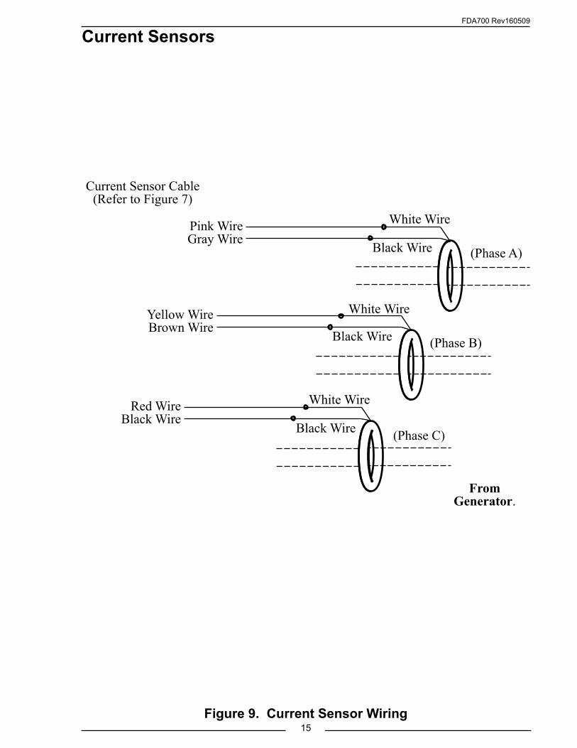
Current Sensor Cable(Refer to Figure 7)
Pink WireGray Wire
Yellow WireBrown Wire
Red WireBlack Wire
White Wire
Black Wire
White Wire
Black Wire
White Wire
Black Wire (Phase A)
(Phase B)
(Phase C)
Figure 9. Current Sensor Wiring
Current Sensors
From Generator.

FDA700 Rev160509
16Figure 10. Star Winding Connections
A
BC
N
120v
120v
120v
Star Circuit
Star Winding Connections
12-Pin Deutsch Receptacle to
Gray ConnectorRefer to Figure 7.
From Generator
N C B A
N C B A To Load
Current Sensors
Voltage Transformers

FDA700 Rev160509
17Figure 11. Delta Winding Connections
Delta Winding Connections
12-Pin Deutsch Receptacle to
Gray ConnectorRefer to Figure 7
From Generator
N C B A
N C B A To Load
Current Sensors
Voltage Transformers
Recommended Delta Circuit Reference Wiring
A
BC
N
120v120v
240v
208v
240v
Note 1: If the voltage reading needs
Calibration, adjust AB (line-4), BC (line-5), CA (line-6).
Ref. OEM Calibration Guide
Note 2: If the phase A & C is split for Neutral, reverse the wiring for
phase B & C.If the phase B & C is split for Neutral, reverse the wiring for
phase A & C.

FDA700 Rev160509
18
NOTES

FDA700 Rev160509
19
NOTES

FDA700 Rev160509
20