Embed Size (px)
Citation preview
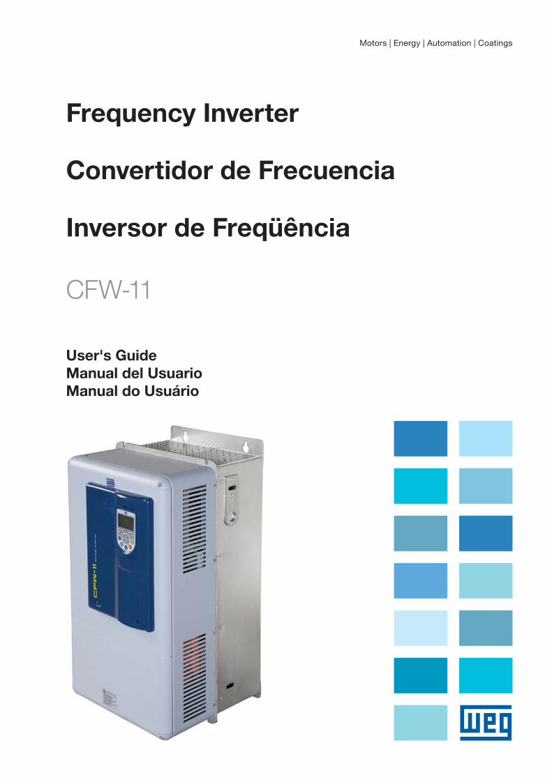
Frequency Inverter
Convertidor de Frecuencia
Inversor de Freqüência
CFW-11
Motors | Energy | Automation | Coatings
User's GuideManual del UsuarioManual do Usuário
03/2009
Series: CFW-11
Language: English
Document: 10000280997 / 00
Models: 142...211 A / 220...230 V
105...211 A / 380...480 V
FREQUENCY
INVERTER
MANUAL

2
Revision Description Chapter
1 First Edition -
Summary of Revisions
Index
CHAPTER 1Safety Instructions
1.1 Safety Warnings in the Manual.....................................................................................................1-1
1.2 Safety Warnings in the Product .....................................................................................................1-1
1.3 Preliminary Recommendations ....................................................................................................1-2
CHAPTER 2General Instructions
2.1 About the Manual ......................................................................................................................2-1
2.2 Terms and Definitions..................................................................................................................2-1
2.3 About the CFW-11 .....................................................................................................................2-4
2.4 Identification Labels for the CFW-11.............................................................................................2-7
2.5 Receiving and Storage ..............................................................................................................2-10
CHAPTER 3Installation and Connection
3.1 Mechanical Installation ...............................................................................................................3-1
3.1.1 Installation Environment.....................................................................................................3-1
3.1.2 Mounting Considerations...................................................................................................3-1
3.1.3 Cabinet Mounting ............................................................................................................3-4
3.1.4 Installation of the Inverter Hoisting Eyes...............................................................................3-5
3.1.5 Installation of the Inverter with Nema 1 Kit (Optional, CFW11XXXXTXON1) on a Wall.............3-6
3.1.6 Access to the Control and Power Terminal Strips...................................................................3-6
3.1.7 Removal of the Cable Passage Plate ...................................................................................3-8
3.1.8 HMI Installation at the Cabinet Door or Command Panel (Remote HMI) ................................3-8
3.2 Electrical Installation ...................................................................................................................3-9
3.2.1 Identification of the Power and Grounding Terminals ............................................................3-9
3.2.2 Power / Grounding Wiring and Fuses................................................................................3-10
3.2.3 Power Connections..........................................................................................................3-14
3.2.3.1 Input Connections ..............................................................................................3-14
3.2.3.1.1 IT Networks ........................................................................................3-15
3.2.3.1.2 Command Fuses .................................................................................3-16
3.2.3.2 Dynamic Braking................................................................................................3-16
3.2.3.2.1 Sizing the Braking Resistor....................................................................3-17
3.2.3.2.2 Installation of the Braking Resistor.........................................................3-18
3.2.3.3 Output Connections ...........................................................................................3-19
3.2.4 Grounding Connections ..................................................................................................3-21
3.2.5 Control Connections .......................................................................................................3-22
3.2.6 Typical Control Connections.............................................................................................3-26
3.3 Installation According to the European Directive of Electromagnetic Compatibility .........................3-29
3.3.1 Conformal Installation .....................................................................................................3-29
3.3.2 Standard Definitions ........................................................................................................3-30
3.3.3 Emission and Immunity Levels...........................................................................................3-31
Index
CHAPTER 4KEYPAD AND DISPLAY
4.1 Integral Keypad - HMI-CFW11 ....................................................................................................4-1
4.2 Parameters Organization.............................................................................................................4-4
CHAPTER 5First Time Power-Up and Start-Up
5.1 Prepare for Start-Up....................................................................................................................5-1
5.2 Start-Up.....................................................................................................................................5-2
5.2.1 Password Setting in P0000 .................................................................................................5-2
5.2.2 Oriented Start-up ..............................................................................................................5-3
5.2.3 Setting Basic Application Parameters ...................................................................................5-5
5.3 Setting Date and Time.................................................................................................................5-8
5.4 Blocking Parameters Modification ................................................................................................5-8
5.5 How to Connect a PC .................................................................................................................5-9
5.6 FLASH Memory Module ..............................................................................................................5-9
CHAPTER 6Troubleshooting and Maintenance
6.1 Operation of the Faults and Alarms..............................................................................................6-1
6.2 Faults, Alarms, and Possible Causes .............................................................................................6-2
6.3 Solutions for the Most Frequent Problems......................................................................................6-5
6.4 Information for Contacting Technical Support................................................................................6-6
6.5 Preventive Maintenance...............................................................................................................6-6
6.5.1 Cleaning Instructions .........................................................................................................6-7
CHAPTER 7Option Kits and Accessories
7.1 Option Kits ................................................................................................................................7-1
7.1.1 Braking IGBT....................................................................................................................7-1
7.1.2 Nema1 Protection Degree..................................................................................................7-1
7.1.3 Safety Stop According to EN 954-1 Category 3 (Pending Certification) ..................................7-1
7.1.4 24 Vdc External Control Power Supply.................................................................................7-2
7.2 Accessories ................................................................................................................................7-3
CHAPTER 8Technical Specifications
8.1 Power Data ................................................................................................................................8-1
8.2 Electrical / General Specifications ................................................................................................8-6
8.2.1 Codes and Standards ........................................................................................................8-7
8.3 Mechanical Data........................................................................................................................8-8
8.4 NEMA1 Kit.................................................................................................................................8-9

Safety Instructions
1-1
1
SAFETY INSTRUCTIONS
This manual provides information for the proper installation and
operation of the CFW-11 frequency inverter.
Only trained and qualified personnel should attempt to install,
start-up, and troubleshoot this type of equipment.
1.1 SAFETY WARNINGS IN THE MANUAL
The following safety warnings are used in this manual:
DANGER!Failure to follow the recommended procedures listed in this warning may result in death, serious
injury, and equipment damage.
ATTENTION!Failure to follow the recommended procedures listed in this warning may result in equipment
damage.
NOTE!This warning provides important information for the proper understanding and operation of the
equipment.
1.2 SAFETY WARNINGS IN THE PRODUCT
The following symbols are attached to the product and require special attention:
Indicates a high voltage warning.
Electrostatic discharge sensitive components.
Do not touch them.
Indicates that a ground (PE) must be connected securely.
Indicates that the cable shield must be grounded.
Indicates a hot surface warning.

Safety Instructions
1-2
1
1.3 PRELIMINARY RECOMMENDATIONS
DANGER!Only trained personnel, with proper qualifications, and familiar with the CFW-11 and associated
machinery shall plan and implent the installation, starting, operation, and maintenance of this
equipment.
The personnel shall follow all the safety instructions described in this manual and/or defined by the
local regulations.
Failure to comply with the safety instructions may result in death, serious injury, and equipment
damage.
NOTE!For the purpose of this manual, qualified personnel are those trained and able to:
1. Install, ground, power-up, and operate the CFW-11 according to this manual and to the current
legal safety procedures;
2. Use the protection equipment according to the established regulations;
3. Provide first aid.
DANGER!Always disconnect the main power supply before touching any electrical device associated with the
inverter.
Several components may remain charged with high voltage and/or in movement (fans), even after
the AC power supply has been disconnected or turned off.
Wait at least 10 minutes to guarantee the fully discharge of capacitors.
Always connect the equipment frame to the ground protection (PE).
ATTENTION!The electronic boards contain components sensitive to electrostatic discharges. Do not touch the
components and terminals directly. If needed, touch first the grounded metal frame or wear an
adequate ground strap.
NOTE!Frequency inverters may cause interference in other electronic devices. Follow the recommendations
listed in Chapter 3 – Installation and Connection, to minimize these effects.
NOTE!Fully read this manual before installing or operating the inverter.
Do not perform a withstand voltage test on any part of the inverter!If needed, please, consult WEG.

Safety Instructions
1-3
1
ATTENTION!Operation of this equipment requires detailed installation and operation instructions provided in the
User's Manual, Software Manual and Manual/Guides for Kits and Accessories. Only User's Manual is
provided on a printed version. The other manuals are provided on the CD supplied with the product.
This CD should be retained with this equipment at all times. A hard copy of this information may be
ordered through your local WEG representative.

Safety Instructions
1-4
1
General Instructions
2-1
2
GENERAL INSTRUCTIONS
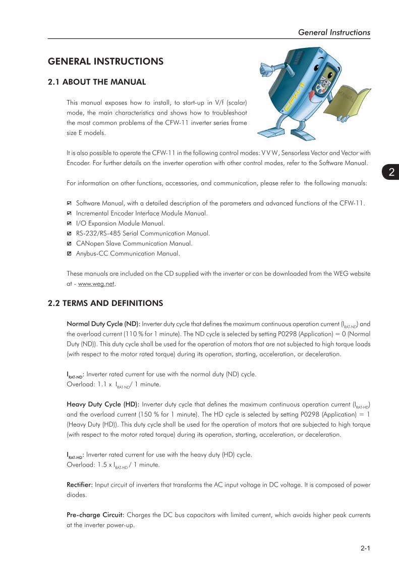
2.1 ABOUT THE MANUAL
This manual exposes how to install, to start-up in V/f (scalar)
mode, the main characteristics and shows how to troubleshoot
the most common problems of the CFW-11 inverter series frame
size E models.
It is also possible to operate the CFW-11 in the following control modes: V V W, Sensorless Vector and Vector with
Encoder. For further details on the inverter operation with other control modes, refer to the Software Manual.
For information on other functions, accessories, and communication, please refer to the following manuals:
Software Manual, with a detailed description of the parameters and advanced functions of the CFW-11.
Incremental Encoder Interface Module Manual.
I/O Expansion Module Manual.
RS-232/RS-485 Serial Communication Manual.
CANopen Slave Communication Manual.
Anybus-CC Communication Manual.
These manuals are included on the CD supplied with the inverter or can be downloaded from the WEG website
at - www.weg.net.
2.2 TERMS AND DEFINITIONS
Normal Duty Cycle (ND): Inverter duty cycle that defines the maximum continuous operation current (IRAT-ND) and
the overload current (110 % for 1 minute). The ND cycle is selected by setting P0298 (Application) = 0 (Normal
Duty (ND)). This duty cycle shall be used for the operation of motors that are not subjected to high torque loads
(with respect to the motor rated torque) during its operation, starting, acceleration, or deceleration.
IRAT-ND: Inverter rated current for use with the normal duty (ND) cycle.
Overload: 1.1 x IRAT-ND/ 1 minute.
Heavy Duty Cycle (HD): Inverter duty cycle that defines the maximum continuous operation current (IRAT-HD)
and the overload current (150 % for 1 minute). The HD cycle is selected by setting P0298 (Application) = 1
(Heavy Duty (HD)). This duty cycle shall be used for the operation of motors that are subjected to high torque
(with respect to the motor rated torque) during its operation, starting, acceleration, or deceleration.
IRAT-HD: Inverter rated current for use with the heavy duty (HD) cycle.
Overload: 1.5 x IRAT-HD / 1 minute.
Rectifier: Input circuit of inverters that transforms the AC input voltage in DC voltage. It is composed of power
diodes.
Pre-charge Circuit: Charges the DC bus capacitors with limited current, which avoids higher peak currents
at the inverter power-up.
General Instructions
2-2
2
DC Bus: Inverter intermediate circuit; DC voltage obtained from the rectification of the AC input voltage or
from an external power supply; feeds the output inverter bridge with IGBTs.
Power modules U, V, and W: Set of two IGBTs of the inverter output phases U, V, and W.
IGBT: Insulated Gate Bipolar Transistor; basic component of the output inverter bridge. The IGBT works as an
electronic switch in the saturated (closed switch) and cut-off (open switch) modes.
Braking IGBT: Works as a switch to activate the braking resistors. It is controlled by the DC bus voltage
level.
PTC: Resistor which resistance value in ohms increases proportionally to the temperature increase; used as a
temperature sensor in electrical motors.
NTC: Resistor which resistance value in ohms decreases proportionally to the temperature increase; used as a
temperature sensor in power modules.
HMI - Human Machine Interface: it is a device that allows the motor control, and the visualization and
modification of the inverter parameters. The CFW-11 HMI presents keys for the motor command, navigation
keys and a graphic LCD display.
FLASH memory: Non-volatile memory that can be electronically written and erased.
RAM memory: Random Access Memory (volatile).
USB: Universal Serial Bus; is a serial bus standard that allows devices to be connected using the ”Plug and
Play” concept.
PE: Protective Earth.
RFI Filter: Radio-Frequency Interference Filter for interference reduction in the Radio-Frequency range.
PWM: Pulse Width Modulation; pulsed voltage that feeds the motor.
Switching frequency: Frequency of the IGBTs switching in the inverter bridge, normally expressed in kHz.
General enable: When activated, this function accelerates the motor via acceleration ramp set in the inverter.
When deactivated, this function immediately blocks the PWM pulses. The general enable function may be
controlled through a digital input set to this function or via serial communication.
Start/Stop: When enabled in the inverter (start), this function accelerates the motor via acceleration ramp up
to the speed reference. When disabled (stop), this function decelerates the motor via deceleration ramp up to
the complete motor stop; at this point, the PWM pulses are blocked. The start/stop function may be controlled
through a digital input set for this function or via serial communication. The operator keys (Start) and
(Stop) of the keypad work in a similar way.
Heatsink: Metal device designed to dissipate the heat generated by the power semiconductors.

General Instructions
2-3
2
PLC: Programmable Logic Controller.
°C: Celsius degree.
°F: Fahrenheit degree.
AC: Alternated Current.
Amp, A: Ampères.
CFM: Cubic Feet per Minute; unit of flow.
cm: Centimeter.
DC: Direct Current.
ft: Foot.
hp: Horse Power = 746 Watts; unit of power, used to indicate the mechanical power of electrical motors.
Hz: Hertz.
in: Inch.
kg: Kilogram = 1000 grams.
kHz: Kilohertz = 1000 Hertz.
l/s: Liters per second.
lb: Pound.
m: Meter.
mA: Miliampère = 0.001 Ampère.
min: Minute.
mm: Millimeter.
ms: Millisecond = 0.001 seconds.
Nm: Newton meter; unit of torque.
rms: "Root mean square"; effective value.
rpm: Revolutions per minute; unit of speed.
s: Second.
V: Volts.
: Ohms.

General Instructions
2-4
2
2.3 ABOUT THE CFW-11
The CFW-11 frequency inverter is a high performance product designed for speed and torque control of three-
phase induction motors. The main characteristic of this product is the “Vectrue” technology, which has the
following advantages:
Scalar control (V/f), V V W, or vector control programmable in the same product;
The vector control may be programmed as “sensorless” (which means standard motors without using
encoders) or as “vector control” with the use of an encoder;
The “sensorless” control allows high torque and fast response, even in very low speeds or at the starting;
The “vector with encoder” control allows high speed precision for the whole speed range (even with a
standstill motor);
"Optimal Braking" function for the vector control, allowing the controlled braking of the motor and avoiding
the use of the braking resistor in some applications;
“Self-Tuning” feature for vector control. It allows the automatic adjustment of the regulators and control
parameters from the identification (also automatic) of the motor parameters and load.
2
General Instructions
2-5
2
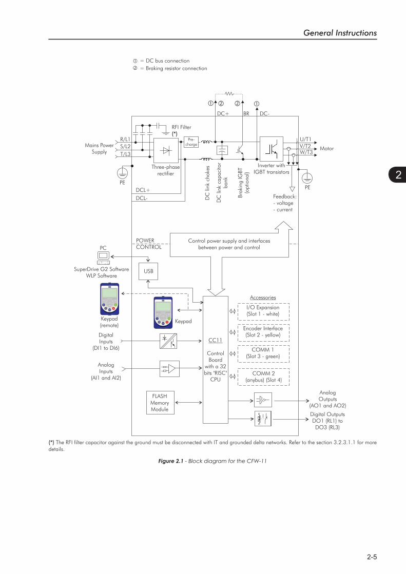
Figure 2.1 - Block diagram for the CFW-11
AnalogInputs
(AI1 and AI2)
FLASHMemoryModule
DigitalInputs
(DI1 to DI6)
Control power supply and interfaces between power and control
USB
PCPOWERCONTROL
Three-phaserectifier
DCL+DCL-
Motor
U/T1R/L1S/L2T/L3
V/T2W/T3
Inverter with IGBT transistors
Mains Power Supply
= DC bus connection = Braking resistor connection
Pre-charge
RFI Filter(*)
DC+ BR DC-
SuperDrive G2 SoftwareWLP Software
Keypad
CC11
ControlBoard
with a 32 bits "RISC"
CPU
AnalogOutputs
(AO1 and AO2)
Digital OutputsDO1 (RL1) toDO3 (RL3)
Keypad (remote)
DC
link
cho
kes
DC
link
cap
acito
r ba
nk
Brak
ing
IGBT
(o
ptio
nal)
Feedback:- voltage- current
PEPE
COMM 2(anybus) (Slot 4)
COMM 1(Slot 3 - green)
Encoder Interface(Slot 2 - yellow)
I/O Expansion(Slot 1 - white)
Accessories
(*) The RFI filter capacitor against the ground must be disconnected with IT and grounded delta networks. Refer to the section 3.2.3.1.1 for more details.
General Instructions
2-6
2
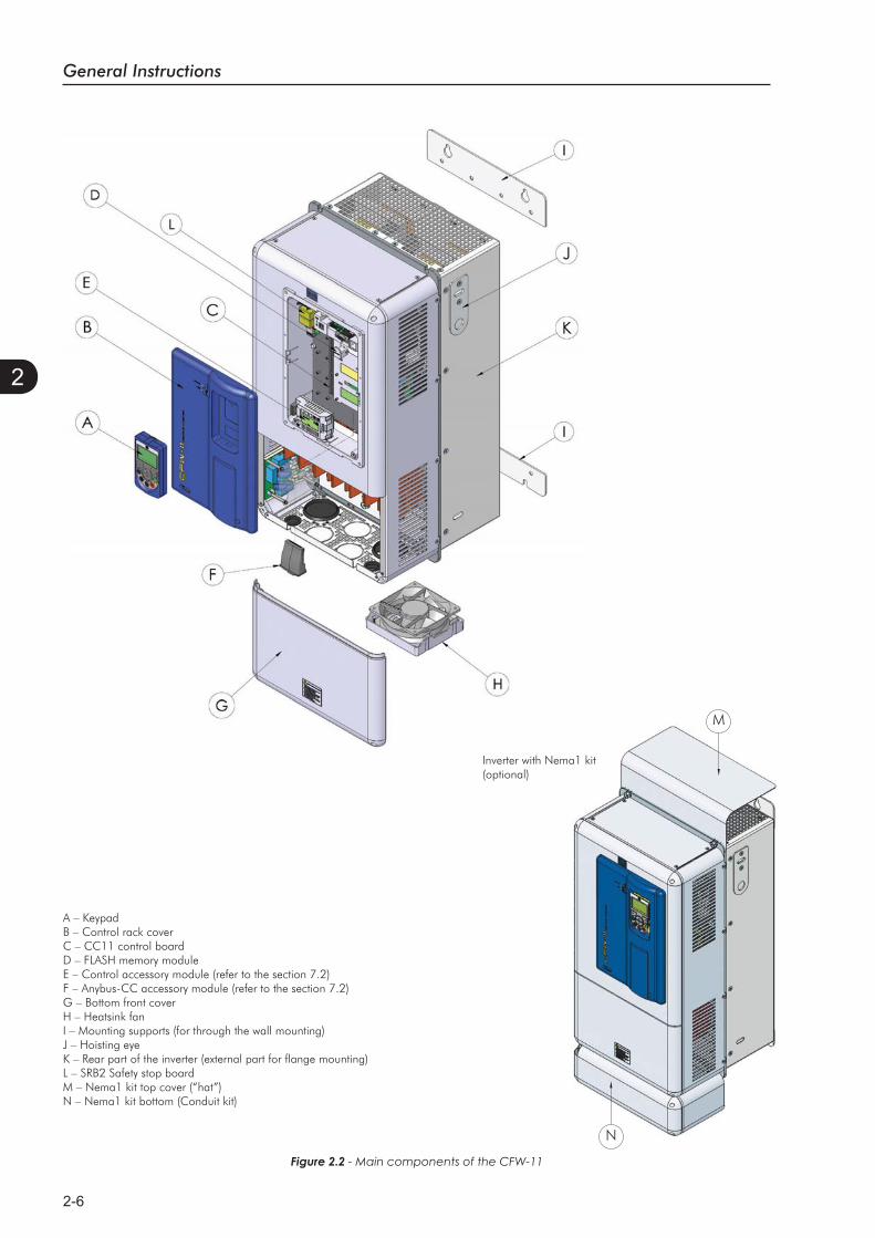
A – KeypadB – Control rack coverC – CC11 control boardD – FLASH memory moduleE – Control accessory module (refer to the section 7.2)F – Anybus-CC accessory module (refer to the section 7.2)G – Bottom front coverH – Heatsink fanI – Mounting supports (for through the wall mounting)J – Hoisting eyeK – Rear part of the inverter (external part for flange mounting)L – SRB2 Safety stop boardM – Nema1 kit top cover (“hat”)N – Nema1 kit bottom (Conduit kit)
Figure 2.2 - Main components of the CFW-11
N
M
Inverter with Nema1 kit(optional)
General Instructions
2-7
2
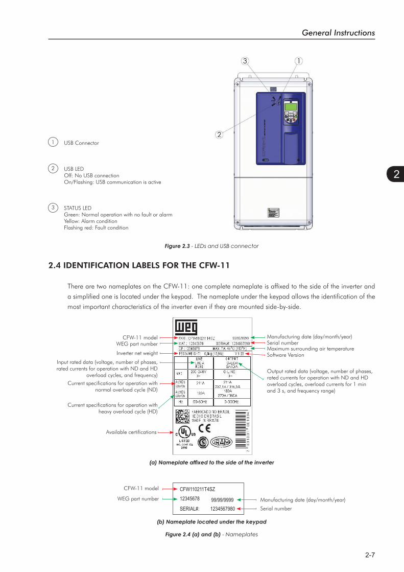
USB Connector
USB LEDOff: No USB connectionOn/Flashing: USB communication is active
STATUS LEDGreen: Normal operation with no fault or alarmYellow: Alarm conditionFlashing red: Fault condition
1
2
3
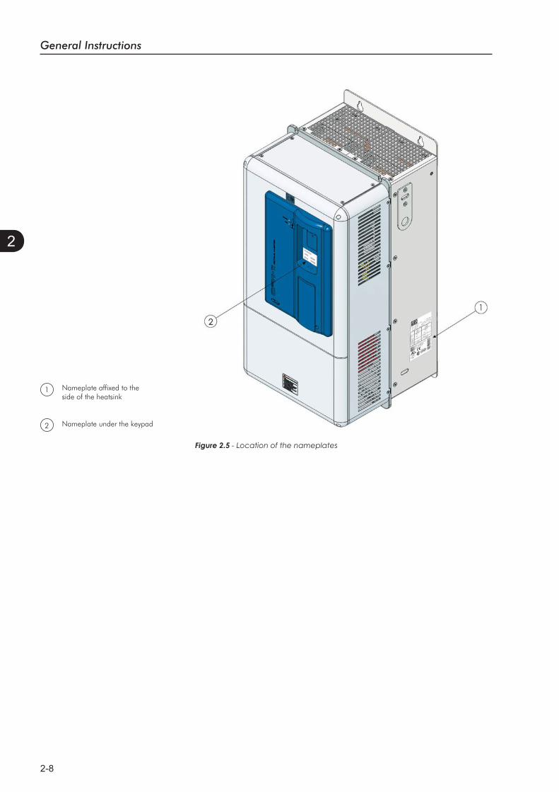
2.4 IDENTIFICATION LABELS FOR THE CFW-11
There are two nameplates on the CFW-11: one complete nameplate is affixed to the side of the inverter and
a simplified one is located under the keypad. The nameplate under the keypad allows the identification of the
most important characteristics of the inverter even if they are mounted side-by-side.
Figure 2.4 (a) and (b) - Nameplates
Figure 2.3 - LEDs and USB connector
Output rated data (voltage, number of phases, rated currents for operation with ND and HD overload cycles, overload currents for 1 min and 3 s, and frequency range)
Input rated data (voltage, number of phases, rated currents for operation with ND and HD
overload cycles, and frequency)
Maximum surrounding air temperatureSoftware Version
Current specifications for operation with heavy overload cycle (HD)
Current specifications for operation with normal overload cycle (ND)
Manufacturing date (day/month/year)CFW-11 modelSerial numberWEG part number
Inverter net weight
Available certifications
CFW110211T4SZ12345678
SERIAL#:99/99/99991234567980
WEG part number
CFW-11 model
Serial number
Manufacturing date (day/month/year)
General Instructions
2-8
2
1
Figure 2.5 - Location of the nameplates
Nameplate affixed to theside of the heatsink
Nameplate under the keypad
1
2
General Instructions
2-9
2
INV
ERTE
R M
OD
ELA
VA
ILA
BLE
OPT
ION
KIT
S (C
AN
BE
INST
ALL
ED IN
TH
E PR
OD
UC
T FR
OM
TH
E FA
CTO
RY)
Refe
r to
the
CFW
-11
serie
s fra
me
size
E m
odel
list
in th
e ch
apte
r 8,
whe
re th
e te
chni
cal s
peci
ficat
ions
of t
he in
verte
rs a
re a
lso
pres
ente
dRe
fer
to c
hapt
er 8
to c
heck
opt
ion
kit a
vaila
bilit
y fo
r ea
ch in
verte
r m
odel
Exam
ple
BRC
FW11
0211
T4
S_
__
__
__
__
__
__
__
_Z
Fiel
dde
scrip
tion
Mar
ket
iden
tific
atio
n(d
efin
esth
e m
anua
l la
ngua
ge a
nd
the
fact
ory
setti
ngs)
WEG
CFW
-11
frequ
ency
inve
rter
serie
s
Rate
d ou
tput
cur
rent
for
use
with
th
e N
orm
al D
uty
(ND
) cyc
leN
umbe
r of
po
wer
pha
ses
Pow
er s
uppl
y vo
ltage
Opt
ion
kit
Encl
osur
ety
peKe
ypad
Brak
ing
RFI f
ilter
Safe
ty s
top
24 V
dc
exte
rnal
pow
er s
uppl
y fo
r co
ntro
l
Spec
ial
hard
war
eSp
ecia
lso
ftwar
eC
hara
cter
that
iden
tifie
sth
e co
de
end
Avai
labl
eop
tions
2 ch
arac
ters
220.
..230
V m
odel
s:0142
=11
5 A
(HD
) / 1
42 A
(ND
)0180
=14
2 A
(HD
) / 1
80 A
(ND
)0211
=18
0 A
(HD
) / 2
11 A
(ND
)
380.
..480
V m
odel
s:0105
=88
A (H
D) /
105
A (N
D)
0142
=11
5 A
(HD
) / 1
42 A
(ND
)0180
=14
2 A
(HD
) / 1
80 A
(ND
)0211
=18
0 A
(HD
) / 2
11 A
(ND
) T=
thre
e-ph
ase
pow
er s
uppl
y2
=22
0...2
30 V
4=
380.
..480
VS=
stan
dard
prod
uct
O=
prod
uct
with
opt
ion
kitBl
ank=
stan
dard
(IP20
)N
1=
Nem
a1
Blan
k=st
anda
rdke
ypad
IC=
noke
ypad
(blin
dco
ver)
Blan
k=st
anda
rd(n
o br
akin
g IG
BT)
DB=
with
brak
ing
IGBT
Blan
k=st
anda
rd(w
ithin
tern
al R
FI
filte
r)
Blan
k=st
anda
rd(s
afet
y st
op
func
tion
is n
ot
avai
labl
e)Y=
with
saf
ety
stop
func
tion
acco
rdin
g to
EN
-954
-1ca
tego
ry 3
Blan
k=st
anda
rd (n
ot
avai
labl
e)W
=24
Vdc
ex
tern
alpo
wer
sup
ply
for
cont
rol
Blan
k=st
anda
rdH
1=
spec
ial
hard
war
e #
1
Blan
k=st
anda
rdS1
=sp
ecia
lso
ftwar
e #
1
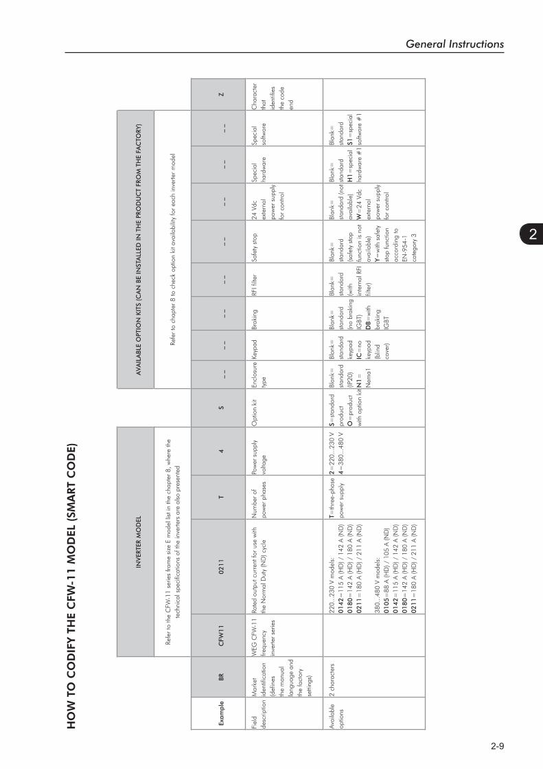
HO
W T
O C
OD
IFY T
HE
CFW
-11 M
OD
EL (
SMA
RT
CO
DE)
General Instructions
2-10
2
2.5 RECEIVING AND STORAGE
The CFW-11 frame size E models are supplied packed in wooden boxes.
There is an identification label affixed to the outside of this package, the same one that is affixed to the side
of the CFW-11 inverter.
Follow the instructions below to remove the CFW-11 from the package:
1- Put the shipping container over a flat and stable area with the assistance of another two people;
2- Open the wood crate;
3- Remove all the packing material (the cardboard or styrofoam protection) before removing the inverter.
Check the following items once the inverter is delivered:
Verify that the CFW-11 nameplate corresponds to the model number on your purchase order;
Inspect the CFW-11 for external damage during transportation.
Report any damage immediately to the carrier that delivered your CFW-11 inverter.
If CFW-11 is to be stored for some time before use, be sure that it is stored in a clean and dry location that
conforms to the storage temperature specification (between -25 °C and 60 °C (-13 °F and 140 °F)). Cover the
inverter to prevent dust accumulation inside it.
ATTENTION!Capacitor reforming is required if drives are stored for long periods of time without power. Refer to
the procedures in item 6.5 - table 6.3.

Installation and Connection
3-1
3
INSTALLATION AND CONNECTIONThis chapter provides information on installing and wiring the CFW-11.
The instructions and guidelines listed in this manual shall be followed
to guarantee personnel and equipment safety, as well as the proper
operation of the inverter.
3.1 MECHANICAL INSTALLATION
3.1.1 Installation Environment
Avoid installing the inverter in an area with:
Direct exposure to sunlight, rain, high humidity, or sea-air;
Inflammable or corrosive gases or liquids;
Excessive vibration;
Dust, metallic particles, and oil mist.
Environment conditions for the operation of the inverter:
Temperature: -10 ºC to 45 ºC (14 °F to 113 °F) - standard conditions (surrounding the inverter).
From 45 ºC to 55 ºC (113 °F to 131 °F) - current derating of 2 % each °C (or 1.11 % each °F) above 45 ºC
(113 °F).
Humidity: from 5 % to 90 % non-condensing.
Altitude: up to 1000 m (3,300 ft) - standard conditions (no derating required).
From 1000 m to 4000 m (3,300 ft to 13,200 ft) - current derating of 1 % each 100 m (or 0.3 % each 100 ft)
above 1000 m (3,300 ft) altitude.
Pollution degree: 2 (according to EN50178 and UL508C) with non-conductive pollution. Condensation shall
not originate conduction through the accumulated residues.
3.1.2 Mounting Considerations
Consult the inverter weight at the table 8.1.
Mount the inverter in the upright position on a flat and vertical surface.
External dimensions and fixing holes position according to the figure 3.1. Refer to the section 8.3 for more
details.
First put the screws on the surface where the inverter will be installed, install the inverter and then tighten the
screws.
Minimum mounting clearances requirements for proper cooling air circulation are specified in figure 3.2.
Do not install heat sensitive components right above the inverter.
Installation and Connection
3-2
3
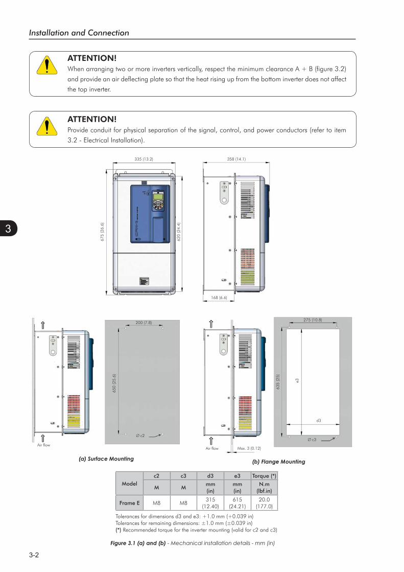
ATTENTION!When arranging two or more inverters vertically, respect the minimum clearance A + B (figure 3.2)
and provide an air deflecting plate so that the heat rising up from the bottom inverter does not affect
the top inverter.
ATTENTION!Provide conduit for physical separation of the signal, control, and power conductors (refer to item
3.2 - Electrical Installation).
Figure 3.1 (a) and (b) - Mechanical installation details - mm (in)
Tolerances for dimensions d3 and e3: +1.0 mm (+0.039 in)Tolerances for remaining dimensions: ±1.0 mm (±0.039 in)(*) Recommended torque for the inverter mounting (valid for c2 and c3)
Modelc2 c3 d3 e3 Torque (*)
M Mmm(in)
mm(in)
N.m(lbf.in)
Frame E M8 M8315
(12.40)615
(24.21)20.0
(177.0)
Air flowAir flow
335 (13.2)
675
(26.
6)
650
(25.
6)
635
(25)
e3
620
(24.
4)
358 (14.1)
168 (6.6)
200 (7.8)275 (10.8)
Max. 3 (0.12)
d3
c2c3
Installation and Connection
3-3
3
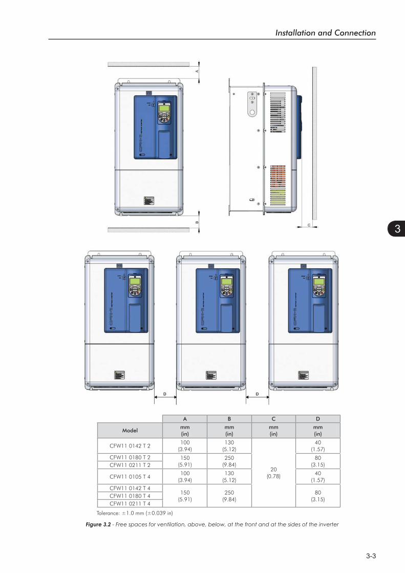
Figure 3.2 - Free spaces for ventilation, above, below, at the front and at the sides of the inverter
Tolerance: ±1.0 mm (±0.039 in)
A B C D
Modelmm(in)
mm(in)
mm(in)
mm(in)
CFW11 0142 T 2100
(3.94)130
(5.12)
20(0.78)
40(1.57)
CFW11 0180 T 2 150(5.91)
250(9.84)
80(3.15)CFW11 0211 T 2
CFW11 0105 T 4100
(3.94)130
(5.12)40
(1.57)
CFW11 0142 T 4150
(5.91)250
(9.84)80
(3.15)CFW11 0180 T 4CFW11 0211 T 4
Installation and Connection
3-4
3
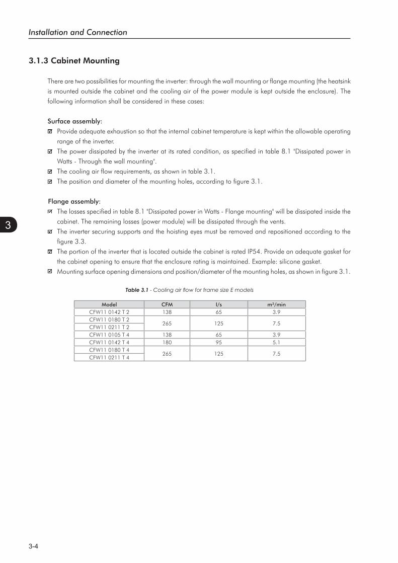
3.1.3 Cabinet Mounting
There are two possibilities for mounting the inverter: through the wall mounting or flange mounting (the heatsink
is mounted outside the cabinet and the cooling air of the power module is kept outside the enclosure). The
following information shall be considered in these cases:
Surface assembly:
Provide adequate exhaustion so that the internal cabinet temperature is kept within the allowable operating
range of the inverter.
The power dissipated by the inverter at its rated condition, as specified in table 8.1 "Dissipated power in
Watts - Through the wall mounting".
The cooling air flow requirements, as shown in table 3.1.
The position and diameter of the mounting holes, according to figure 3.1.
Flange assembly:
The losses specified in table 8.1 "Dissipated power in Watts - Flange mounting" will be dissipated inside the
cabinet. The remaining losses (power module) will be dissipated through the vents.
The inverter securing supports and the hoisting eyes must be removed and repositioned according to the
figure 3.3.
The portion of the inverter that is located outside the cabinet is rated IP54. Provide an adequate gasket for
the cabinet opening to ensure that the enclosure rating is maintained. Example: silicone gasket.
Mounting surface opening dimensions and position/diameter of the mounting holes, as shown in figure 3.1.
Table 3.1
Model CFM I/s m³/minCFW11 0142 T 2 138 65 3.9CFW11 0180 T 2
265 125 7.5CFW11 0211 T 2CFW11 0105 T 4 138 65 3.9CFW11 0142 T 4 180 95 5.1CFW11 0180 T 4
265 125 7.5CFW11 0211 T 4
Installation and Connection
3-5
3
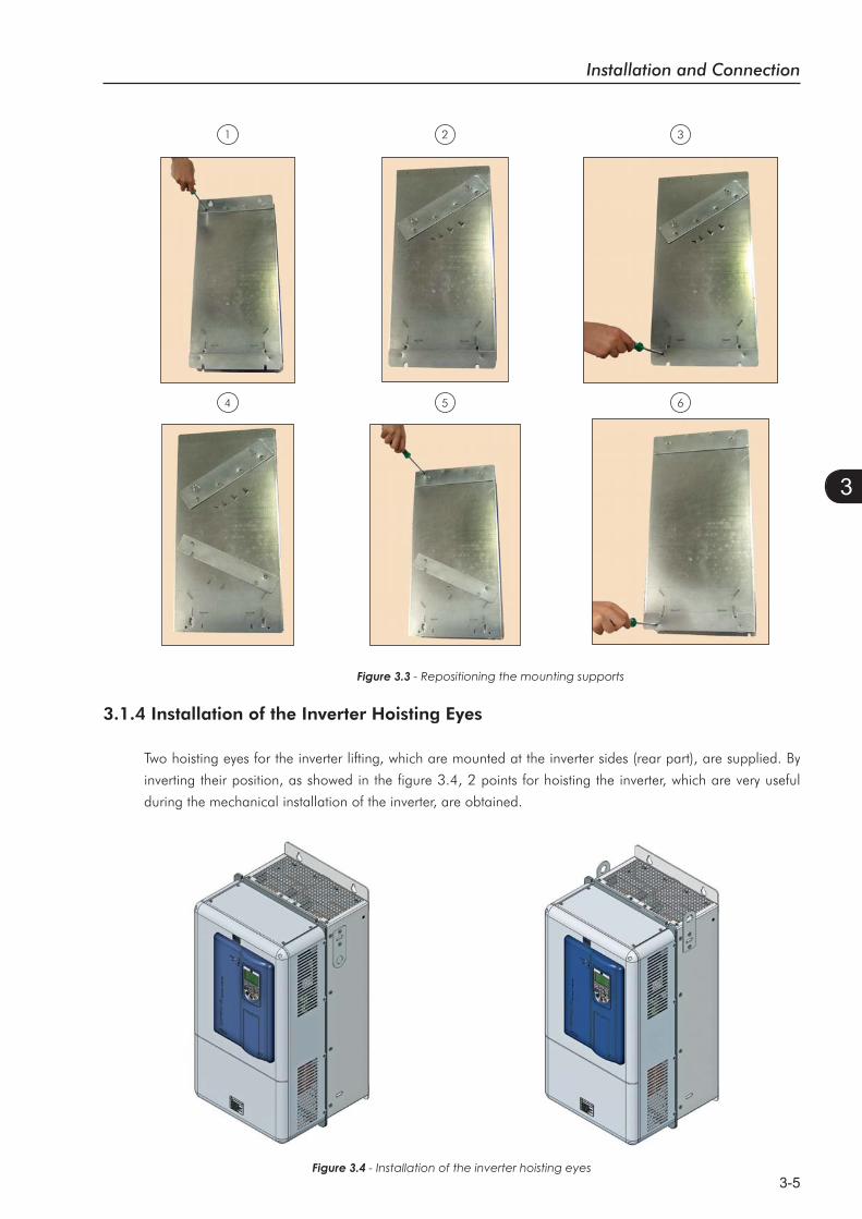
Figure 3.3 - Repositioning the mounting supports
654
321
3.1.4 Installation of the Inverter Hoisting Eyes
Two hoisting eyes for the inverter lifting, which are mounted at the inverter sides (rear part), are supplied. By
inverting their position, as showed in the figure 3.4, 2 points for hoisting the inverter, which are very useful
during the mechanical installation of the inverter, are obtained.
Figure 3.4 - Installation of the inverter hoisting eyes
Installation and Connection
3-6
3
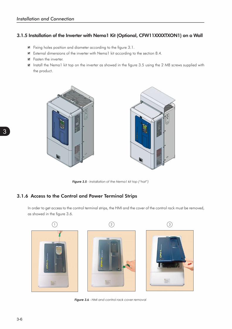
3.1.5 Installation of the Inverter with Nema1 Kit (Optional, CFW11XXXXTXON1) on a Wall
Fixing holes position and diameter according to the figure 3.1.
External dimensions of the inverter with Nema1 kit according to the section 8.4.
Fasten the inverter.
Install the Nema1 kit top on the inverter as showed in the figure 3.5 using the 2 M8 screws supplied with
the product.
Figure 3.5 - Installation of the Nema1 kit top (“hat”)
3.1.6 Access to the Control and Power Terminal Strips
In order to get access to the control terminal strips, the HMI and the cover of the control rack must be removed,
as showed in the figure 3.6.
Figure 3.6 - HMI and control rack cover removal
321
Installation and Connection
3-7
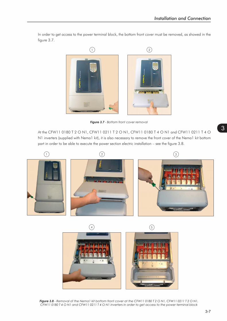
3Figure 3.7 - Bottom front cover removal
In order to get access to the power terminal block, the bottom front cover must be removed, as showed in the
figure 3.7.
21
At the CFW11 0180 T 2 O N1, CFW11 0211 T 2 O N1, CFW11 0180 T 4 O N1 and CFW11 0211 T 4 O
N1 inverters (supplied with Nema1 kit), it is also necessary to remove the front cover of the Nema1 kit bottom
part in order to be able to execute the power section electric installation – see the figure 3.8.
1 2 3
4 5
Figure 3.8 - Removal of the Nema1 kit bottom front cover at the CFW11 0180 T 2 O N1, CFW11 0211 T 2 O N1, CFW11 0180 T 4 O N1 and CFW11 0211 T 4 O N1 inverters in order to get access to the power terminal block

Installation and Connection
3-8
3
3.1.7 Removal of the Cable Passage Plate
When it is not necessary neither IP20 nor Nema1 protection degree, the cable passage plate may be removed
in order to make the inverter electric installation easier. Remove the 4 M4 screws, according to the procedure
presented in the figure 3.9.3
21
Figure 3.9 - Removal of the cable passage plate
3.1.8 HMI Installation at the Cabinet Door or Command Panel (Remote HMI)
35.0 [1.38]
28.5 [1.12]
113.
0 [4
.45]
103.
0 [4
.06]
23.4
[0.9
2]
16.0
[0.6
3]
23.5 [0.93]
65.0 [2.56]
4.0 [0.16] (3X)
Figure 3.10 - Data for the HMI installation at the cabinet door or command panel – mm [in]
The keypad frame accessory can also be used to fix the HMI, as mentioned in the table 7.2.

Installation and Connection
3-9
3
3.2 ELECTRICAL INSTALLATION
DANGER!The following information is merely a guide for proper installation. Comply with applicable local
regulations for electrical installations.
DANGER!Make sure the AC power supply is disconnected before starting the installation.
ATTENTION!Integral solid state short circuit protection does not provide branch circuit protection. Branch circuit
protection must be provided in accordance with applicable local codes.
3.2.1 Identification of the Power and Grounding Terminals
R/L1, S/L2, T/L3: AC power supply.
U/T1, V/T2, W/T3: motor connection.
DC+: this is the positive potential terminal in the DC bus circuit.
BR: braking resistor connection.
DC-: this is the negative potential terminal in the DC bus circuit.
DCL+: positive pole of the rectifier output voltage.
DCL-: negative pole of the rectifier output voltage.
Figure 3.11
Ground(4xM8, 4xM5)
Installation and Connection
3-10
3
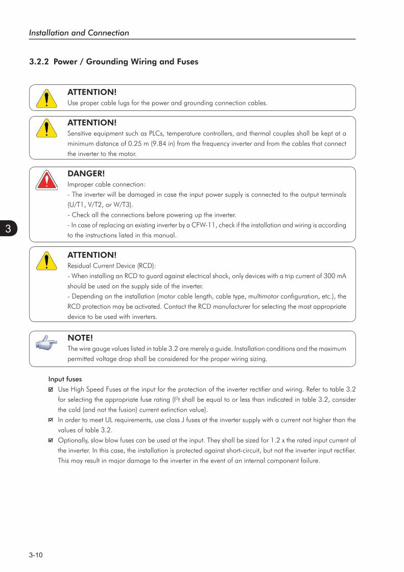
3.2.2 Power / Grounding Wiring and Fuses
ATTENTION!Use proper cable lugs for the power and grounding connection cables.
ATTENTION!Sensitive equipment such as PLCs, temperature controllers, and thermal couples shall be kept at a
minimum distance of 0.25 m (9.84 in) from the frequency inverter and from the cables that connect
the inverter to the motor.
DANGER!Improper cable connection:
- The inverter will be damaged in case the input power supply is connected to the output terminals
(U/T1, V/T2, or W/T3).
- Check all the connections before powering up the inverter.
- In case of replacing an existing inverter by a CFW-11, check if the installation and wiring is according
to the instructions listed in this manual.
ATTENTION!Residual Current Device (RCD):
- When installing an RCD to guard against electrical shock, only devices with a trip current of 300 mA
should be used on the supply side of the inverter.
- Depending on the installation (motor cable length, cable type, multimotor configuration, etc.), the
RCD protection may be activated. Contact the RCD manufacturer for selecting the most appropriate
device to be used with inverters.
NOTE!The wire gauge values listed in table 3.2 are merely a guide. Installation conditions and the maximum
permitted voltage drop shall be considered for the proper wiring sizing.
Input fuses
Use High Speed Fuses at the input for the protection of the inverter rectifier and wiring. Refer to table 3.2
for selecting the appropriate fuse rating (I2t shall be equal to or less than indicated in table 3.2, consider
the cold (and not the fusion) current extinction value).
In order to meet UL requirements, use class J fuses at the inverter supply with a current not higher than the
values of table 3.2.
Optionally, slow blow fuses can be used at the input. They shall be sized for 1.2 x the rated input current of
the inverter. In this case, the installation is protected against short-circuit, but not the inverter input rectifier.
This may result in major damage to the inverter in the event of an internal component failure.
Installation and Connection
3-11
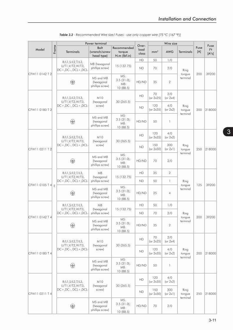
3
Table 3.2
Model
Fram
e
Power terminalOver-load class
Wire sizeFuse [A]
Fuse I2t
[A2s]TerminalsBolt
(wrench/screwhead type)
Recommended torque
N.m (lbf.in)mm2 AWG Terminals
CFW11 0142 T 2
E
R/L1,S/L2,T/L3,U/T1,V/T2,W/T3,
DC+,DC-, DCL+,DCL-
M8 (hexagonal phillips screw)
15 (132.75)
HD 50 1/0
Ringtongueterminal
200 39200
ND 70 2/0
M5 and M8 (hexagonal
phillips screw)
M5:3.5 (31.0);
M8: 10 (88.5)
HD/ND 35 2
CFW11 0180 T 2
R/L1,S/L2,T/L3,U/T1,V/T2,W/T3,
DC+,DC-, DCL+,DCL-
M10(hexagonal
screw)30 (265.5)
HD70
(or 2x25)2/0
(or 2x4)
Ringtongueterminal
200 218000ND
120 (or 2x35)
4/0 (or 2x2)
M5 and M8 (hexagonal
phillips screw)
M5:3.5 (31.0);
M8:10 (88.5)
HD/ND 50 1
CFW11 0211 T 2
R/L1,S/L2,T/L3,U/T1,V/T2,W/T3,
DC+,DC-, DCL+,DCL-
M10(hexagonal
screw)30 (265.5)
HD120
(or 2x35)4/0
(or 2x2)
Ringtongueterminal
250 218000ND
150 (or 2x50)
300 (or 2x1)
M5 and M8 (hexagonal
phillips screw)
M5:3.5 (31.0);
M8:10 (88.5)
HD/ND 70 2/0
CFW11 0105 T 4
R/L1,S/L2,T/L3,U/T1,V/T2,W/T3,
DC+,DC-, DCL+,DCL-
M8(hexagonal
phillips screw)15 (132.75)
HD 35 2
Ringtongueterminal
125 39200ND 50 1
M5 and M8 (hexagonal
phillips screw)
M5:3.5 (31.0);
M8:10 (88.5)
HD/ND 25 4
CFW11 0142 T 4
R/L1,S/L2,T/L3,U/T1,V/T2,W/T3,
DC+,DC-, DCL+,DCL-
M8(hexagonal
phillips screw)15 (132.75)
HD 50 1/0
Ringtongueterminal
200 39200ND 70 2/0
M5 and M8 (hexagonal
phillips screw)
M5:3.5 (31.0);
M8:10 (88.5)
HD/ND 35 2
CFW11 0180 T 4
R/L1,S/L2,T/L3,U/T1,V/T2,W/T3,
DC+,DC-, DCL+,DCL-
M10(hexagonal
screw)30 (265.5)
HD70
(or 2x25)2/0
(or 2x4)
Ringtongueterminal
200 218000ND
120 (or 2x35)
4/0 (or 2x2)
M5 and M8 (hexagonal
phillips screw)
M5:3.5 (31.0);
M8:10 (88.5)
HD/ND 50 1
CFW11 0211 T 4
R/L1,S/L2,T/L3,U/T1,V/T2,W/T3,
DC+,DC-, DCL+,DCL-
M10(hexagonal
screw)30 (265.5)
HD120
(or 2x35)4/0
(or 2x2)
Ringtongueterminal
250 218000ND150
(or 2x50)300
(or 2x1)
M5 and M8 (hexagonal
phillips screw)
M5:3.5 (31.0);
M8:10 (88.5)
HD/ND 70 2/0
Installation and Connection
3-12
3
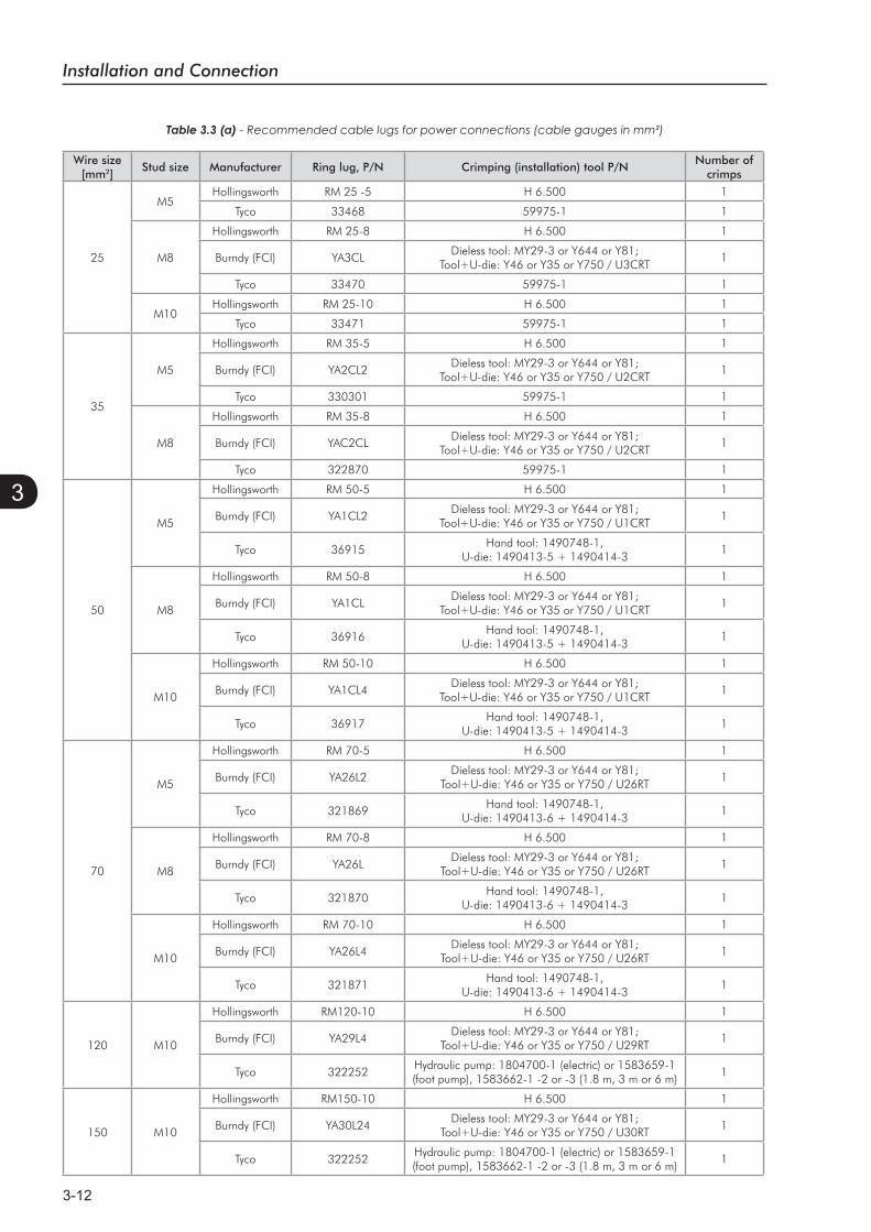
Table 3.3 (a) - Recommended cable lugs for power connections (cable gauges in mm²)
Wire size [mm2]
Stud size Manufacturer Ring lug, P/N Crimping (installation) tool P/NNumber of
crimps
25
M5Hollingsworth RM 25 -5 H 6.500 1
Tyco 33468 59975-1 1
M8
Hollingsworth RM 25-8 H 6.500 1
Burndy (FCI) YA3CLDieless tool: MY29-3 or Y644 or Y81;
Tool+U-die: Y46 or Y35 or Y750 / U3CRT1
Tyco 33470 59975-1 1
M10Hollingsworth RM 25-10 H 6.500 1
Tyco 33471 59975-1 1
35
M5
Hollingsworth RM 35-5 H 6.500 1
Burndy (FCI) YA2CL2Dieless tool: MY29-3 or Y644 or Y81;
Tool+U-die: Y46 or Y35 or Y750 / U2CRT1
Tyco 330301 59975-1 1
M8
Hollingsworth RM 35-8 H 6.500 1
Burndy (FCI) YAC2CLDieless tool: MY29-3 or Y644 or Y81;
Tool+U-die: Y46 or Y35 or Y750 / U2CRT1
Tyco 322870 59975-1 1
50
M5
Hollingsworth RM 50-5 H 6.500 1
Burndy (FCI) YA1CL2Dieless tool: MY29-3 or Y644 or Y81;
Tool+U-die: Y46 or Y35 or Y750 / U1CRT1
Tyco 36915Hand tool: 1490748-1,
U-die: 1490413-5 + 1490414-31
M8
Hollingsworth RM 50-8 H 6.500 1
Burndy (FCI) YA1CLDieless tool: MY29-3 or Y644 or Y81;
Tool+U-die: Y46 or Y35 or Y750 / U1CRT1
Tyco 36916Hand tool: 1490748-1,
U-die: 1490413-5 + 1490414-31
M10
Hollingsworth RM 50-10 H 6.500 1
Burndy (FCI) YA1CL4Dieless tool: MY29-3 or Y644 or Y81;
Tool+U-die: Y46 or Y35 or Y750 / U1CRT1
Tyco 36917Hand tool: 1490748-1,
U-die: 1490413-5 + 1490414-31
70
M5
Hollingsworth RM 70-5 H 6.500 1
Burndy (FCI) YA26L2Dieless tool: MY29-3 or Y644 or Y81;
Tool+U-die: Y46 or Y35 or Y750 / U26RT1
Tyco 321869Hand tool: 1490748-1,
U-die: 1490413-6 + 1490414-31
M8
Hollingsworth RM 70-8 H 6.500 1
Burndy (FCI) YA26LDieless tool: MY29-3 or Y644 or Y81;
Tool+U-die: Y46 or Y35 or Y750 / U26RT1
Tyco 321870Hand tool: 1490748-1,
U-die: 1490413-6 + 1490414-31
M10
Hollingsworth RM 70-10 H 6.500 1
Burndy (FCI) YA26L4Dieless tool: MY29-3 or Y644 or Y81;
Tool+U-die: Y46 or Y35 or Y750 / U26RT1
Tyco 321871Hand tool: 1490748-1,
U-die: 1490413-6 + 1490414-31
120 M10
Hollingsworth RM120-10 H 6.500 1
Burndy (FCI) YA29L4Dieless tool: MY29-3 or Y644 or Y81;
Tool+U-die: Y46 or Y35 or Y750 / U29RT1
Tyco 322252Hydraulic pump: 1804700-1 (electric) or 1583659-1 (foot pump), 1583662-1 -2 or -3 (1.8 m, 3 m or 6 m)
1
150 M10
Hollingsworth RM150-10 H 6.500 1
Burndy (FCI) YA30L24Dieless tool: MY29-3 or Y644 or Y81;
Tool+U-die: Y46 or Y35 or Y750 / U30RT1
Tyco 322252Hydraulic pump: 1804700-1 (electric) or 1583659-1 (foot pump), 1583662-1 -2 or -3 (1.8 m, 3 m or 6 m)
1
Installation and Connection
3-13
3
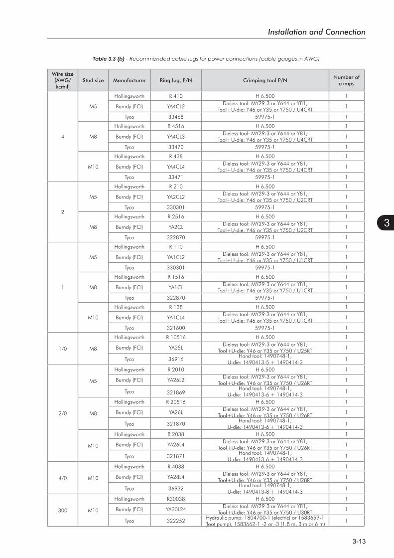
Table 3.3 (b) - Recommended cable lugs for power connections (cable gauges in AWG)
Wire size [AWG/ kcmil]
Stud size Manufacturer Ring lug, P/N Crimping tool P/NNumber of
crimps
4
M5
Hollingsworth R 410 H 6.500 1
Burndy (FCI) YA4CL2Dieless tool: MY29-3 or Y644 or Y81;
Tool+U-die: Y46 or Y35 or Y750 / U4CRT1
Tyco 33468 59975-1 1
M8
Hollingsworth R 4516 H 6.500 1
Burndy (FCI) YA4CL3Dieless tool: MY29-3 or Y644 or Y81;
Tool+U-die: Y46 or Y35 or Y750 / U4CRT1
Tyco 33470 59975-1 1
M10
Hollingsworth R 438 H 6.500 1
Burndy (FCI) YA4CL4Dieless tool: MY29-3 or Y644 or Y81;
Tool+U-die: Y46 or Y35 or Y750 / U4CRT1
Tyco 33471 59975-1 1
2
M5
Hollingsworth R 210 H 6.500 1
Burndy (FCI) YA2CL2Dieless tool: MY29-3 or Y644 or Y81;
Tool+U-die: Y46 or Y35 or Y750 / U2CRT1
Tyco 330301 59975-1 1
M8
Hollingsworth R 2516 H 6.500 1
Burndy (FCI) YA2CLDieless tool: MY29-3 or Y644 or Y81;
Tool+U-die: Y46 or Y35 or Y750 / U2CRT1
Tyco 322870 59975-1 1
1
M5
Hollingsworth R 110 H 6.500 1
Burndy (FCI) YA1CL2Dieless tool: MY29-3 or Y644 or Y81;
Tool+U-die: Y46 or Y35 or Y750 / U1CRT1
Tyco 330301 59975-1 1
M8
Hollingsworth R 1516 H 6.500 1
Burndy (FCI) YA1CLDieless tool: MY29-3 or Y644 or Y81;
Tool+U-die: Y46 or Y35 or Y750 / U1CRT1
Tyco 322870 59975-1 1
M10
Hollingsworth R 138 H 6.500 1
Burndy (FCI) YA1CL4Dieless tool: MY29-3 or Y644 or Y81;
Tool+U-die: Y46 or Y35 or Y750 / U1CRT1
Tyco 321600 59975-1 1
1/0 M8
Hollingsworth R 10516 H 6.500 1
Burndy (FCI) YA25LDieless tool: MY29-3 or Y644 or Y81;
Tool+U-die: Y46 or Y35 or Y750 / U25RT1
Tyco 36916Hand tool: 1490748-1,
U-die: 1490413-5 + 1490414-31
2/0
M5
Hollingsworth R 2010 H 6.500 1
Burndy (FCI) YA26L2Dieless tool: MY29-3 or Y644 or Y81;
Tool+U-die: Y46 or Y35 or Y750 / U26RT1
Tyco 321869Hand tool: 1490748-1,
U-die: 1490413-6 + 1490414-31
M8
Hollingsworth R 20516 H 6.500 1
Burndy (FCI) YA26LDieless tool: MY29-3 or Y644 or Y81;
Tool+U-die: Y46 or Y35 or Y750 / U26RT1
Tyco 321870Hand tool: 1490748-1,
U-die: 1490413-6 + 1490414-31
M10
Hollingsworth R 2038 H 6.500 1
Burndy (FCI) YA26L4Dieless tool: MY29-3 or Y644 or Y81;
Tool+U-die: Y46 or Y35 or Y750 / U26RT1
Tyco 321871Hand tool: 1490748-1,
U-die: 1490413-6 + 1490414-31
4/0 M10
Hollingsworth R 4038 H 6.500 1
Burndy (FCI) YA28L4Dieless tool: MY29-3 or Y644 or Y81;
Tool+U-die: Y46 or Y35 or Y750 / U28RT1
Tyco 36932Hand tool: 1490748-1,
U-die: 1490413-8 + 1490414-31
300 M10
Hollingsworth R30038 H 6.500 1
Burndy (FCI) YA30L24Dieless tool: MY29-3 or Y644 or Y81;
Tool+U-die: Y46 or Y35 or Y750 / U30RT1
Tyco 322252Hydraulic pump: 1804700-1 (electric) or 1583659-1 (foot pump), 1583662-1 -2 or -3 (1.8 m, 3 m or 6 m)
1
Installation and Connection
3-14
3
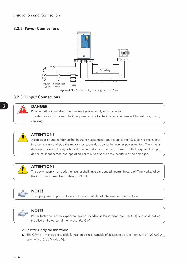
3.2.3.1 Input Connections
DANGER!Provide a disconnect device for the input power supply of the inverter.
This device shall disconnect the input power supply for the inverter when needed (for instance, during
servicing).
ATTENTION!A contactor or another device that frequently disconnects and reapplies the AC supply to the inverter
in order to start and stop the motor may cause damage to the inverter power section. The drive is
designed to use control signals for starting and stopping the motor. If used for that purpose, the input
device must not exceed one operation per minute otherwise the inverter may be damaged.
ATTENTION!The power supply that feeds the inverter shall have a grounded neutral. In case of IT networks, follow
the instructions described in item 3.2.3.1.1.
NOTE!The input power supply voltage shall be compatible with the inverter rated voltage.
NOTE!Power factor correction capacitors are not needed at the inverter input (R, S, T) and shall not be
installed at the output of the inverter (U, V, W).
AC power supply considerations
The CFW-11 inverters are suitable for use on a circuit capable of deliviering up to a maximum of 100,000 Arms
symmetrical (230 V / 480 V).
Figure 3.12 - Power and grounding connections
3.2.3 Power Connections
ShieldingPE
DisconnectSwitch
Fuses
RSTPowerSupply
PE W V UPE R S T U V W PE
Installation and Connection
3-15
3
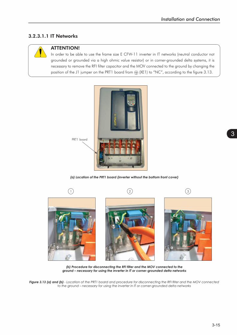
3.2.3.1.1 IT Networks
ATTENTION!In order to be able to use the frame size E CFW-11 inverter in IT networks (neutral conductor not
grounded or grounded via a high ohmic value resistor) or in corner-grounded delta systems, it is
necessary to remove the RFI filter capacitor and the MOV connected to the ground by changing the
position of the J1 jumper on the PRT1 board from (XE1) to “NC”, according to the figure 3.13.
PRT1 board
321
Figure 3.13 (a) and (b)to the ground – necessary for using the inverter in IT or corner-grounded delta networks

Installation and Connection
3-16
3
3.2.3.1.2 Command Fuses
Besides the RFI filter capacitors and the MOV’s, the PRT1 board also has 3 fuses for protecting the inverter
command circuit.
The PRT1 board location is presented in the figure 3.13 (a).
The location of the PRT1 fuses is presented in the figure 3.13 (b).
See below the specification of the used command fuses:
Slow blow fuse 0.5 A / 600 V;
Manufacturer: Cooper Bussmann;
Part number: FNQ-R-1/2;
WEG part number: 10411493.
Consider the following items for the use of protection devices on the supply side of the inverter such as residual
current devices or isolation monitors:
- The detection of a phase-to-ground short-circuit or an insulation fault shall be processed by the user, i.e., the
user shall decide whether to indicate the fault and/or block the inverter operation.
- Contact the RCD manufacturer for selecting the most appropriate device to be used with inverters in order to
avoid nuisance tripping due to the high frequency leakage currents that flow through the leakage capacitances
of the inverter, cable, and motor system to the ground.
3.2.3.2 Dynamic Braking
ATTENTION!For the CFW-11 frame size E models, only those with the DB option (CFW11XXXXTXODB) have the
braking IGBT incorporated to the product.
The braking torque that can be obtained from the frequency inverter without braking resistors varies from 10 %
to 35 % of the motor rated torque.
Braking resistors shall be used to obtain higher braking torques. In this case, the energy regenerated in excess
is dissipated in a resistor mounted externally to the inverter.
This type of braking is used in cases where short deceleration times are desired or when high inertia loads are
driven.
For the vector control mode, there is the possibility of using the “Optimal Braking”, eliminating in many cases
the need of dynamic braking use.
NOTE!Set P0151 and P0185 to their maximum values (400 V or 800 V) when using dynamic braking.
Installation and Connection
3-17
3
3.2.3.2.1 Sizing the Braking Resistor
The following application data shall be considered for the adequate sizing of the braking resistor:
- Desired deceleration time;
- Load inertia;
- Braking duty cycle.
In any case, the effective current value and the maximum braking current value presented in table 3.4 shall
be respected.
The maximum braking current defines the minimum braking resistor value in ohms.
The DC bus voltage level for the activation of the dynamic braking function is defined by parameter P0153
(dynamic braking level).
The power of the braking resistor is a function of the deceleration time, the load inertia, and the load torque.
For most applications, a braking resistor with the value in ohms indicated in table 3.4 and the power of 20 %
of the rated driven motor power. Use wire type resistors in a ceramic support with adequate insulation voltage
and capable of withstanding high instantaneous power with respect to rated power. For critical applications with
very short deceleration times and high inertia loads (ex.: centrifuges) or short duration cycles, consult WEG for
the adequate sizing of the braking resistor.
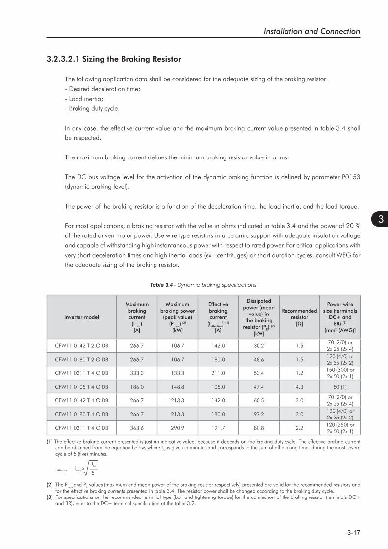
Table 3.4
Inverter model
Maximumbrakingcurrent
(Imax)[A]
Maximumbraking power (peak value)
(Pmax)(2)
[kW]
Effectivebrakingcurrent
(Ieffective)(1)
[A]
Dissipatedpower (mean
value) in the braking
resistor (PR)(2)
[kW]
Recommended resistor
Power wire size (terminals
DC+ and BR) (3)
[mm2 (AWG)]
CFW11 0142 T 2 O DB 266.7 106.7 142.0 30.2 1.570 (2/0) or 2x 25 (2x 4)
CFW11 0180 T 2 O DB 266.7 106.7 180.0 48.6 1.5120 (4/0) or 2x 35 (2x 2)
CFW11 0211 T 4 O DB 333.3 133.3 211.0 53.4 1.2150 (300) or 2x 50 (2x 1)
CFW11 0105 T 4 O DB 186.0 148.8 105.0 47.4 4.3 50 (1)
CFW11 0142 T 4 O DB 266.7 213.3 142.0 60.5 3.070 (2/0) or 2x 25 (2x 4)
CFW11 0180 T 4 O DB 266.7 213.3 180.0 97.2 3.0120 (4/0) or 2x 35 (2x 2)
CFW11 0211 T 4 O DB 363.6 290.9 191.7 80.8 2.2120 (250) or 2x 50 (2x 1)
(1) The effective braking current presented is just an indicative value, because it depends on the braking duty cycle. The effective braking current can be obtained from the equation below, where tbr is given in minutes and corresponds to the sum of all braking times during the most severe cycle of 5 (five) minutes.
Ieffective = Imax x tbr
5
(2) The Pmax and PR values (maximum and mean power of the braking resistor respectively) presented are valid for the recommended resistors and for the effective braking currents presented in table 3.4. The resistor power shall be changed according to the braking duty cycle.
(3) For specifications on the recommended terminal type (bolt and tightening torque) for the connection of the braking resistor (terminals DC+ and BR), refer to the DC+ terminal specification at the table 3.2.
Installation and Connection
3-18
3
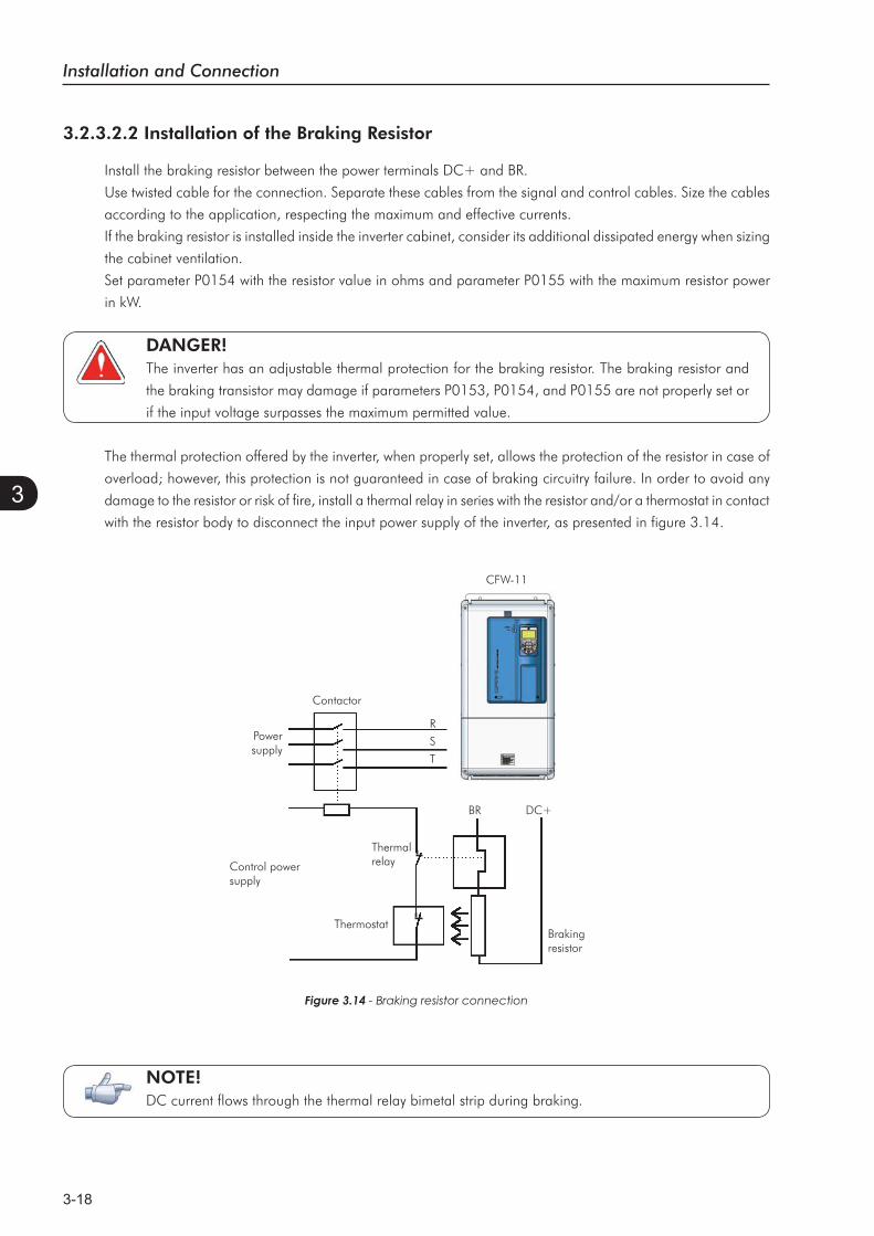
Powersupply
ThermostatBrakingresistor
ThermalrelayControl power
supply
Contactor
CFW-11
BR DC+
Figure 3.14 - Braking resistor connection
R
S
T
NOTE! DC current flows through the thermal relay bimetal strip during braking.
3.2.3.2.2 Installation of the Braking Resistor
Install the braking resistor between the power terminals DC+ and BR.
Use twisted cable for the connection. Separate these cables from the signal and control cables. Size the cables
according to the application, respecting the maximum and effective currents.
If the braking resistor is installed inside the inverter cabinet, consider its additional dissipated energy when sizing
the cabinet ventilation.
Set parameter P0154 with the resistor value in ohms and parameter P0155 with the maximum resistor power
in kW.
DANGER!The inverter has an adjustable thermal protection for the braking resistor. The braking resistor and
the braking transistor may damage if parameters P0153, P0154, and P0155 are not properly set or
if the input voltage surpasses the maximum permitted value.
The thermal protection offered by the inverter, when properly set, allows the protection of the resistor in case of
overload; however, this protection is not guaranteed in case of braking circuitry failure. In order to avoid any
damage to the resistor or risk of fire, install a thermal relay in series with the resistor and/or a thermostat in contact
with the resistor body to disconnect the input power supply of the inverter, as presented in figure 3.14.
Installation and Connection
3-19
3
3.2.3.3 Output Connections
ATTENTION!The inverter has an electronic motor overload protection that shall be adjusted according to the
driven motor. When several motors are connected to the same inverter, install individual overload
relays for each motor.
ATTENTION!The motor overload protection available at the CFW-11 is in accordance with the IEC60947-4-2 and UL508C standards.Important considerations for the UL508C:
Trip current equal to 1.25 times the motor rated current (P0401) adjusted in the oriented start-up menu.The parameter P0159 maximum setting (Motor Thermal Class) is 3 (Class 20).The parameter P0398 maximum setting (Motor Service Factor) is 1.15.
ATTENTION!If a disconnect switch or a contactor is installed between the inverter and the motor, never operate
them with a spinning motor or with voltage at the inverter output.
The characteristics of the cable used for the inverter and motor interconnection, as well as the physical location
are extremely important to avoid electromagnetic interference in other equipment and to not affect the life cycle
of motor windings and motor bearings controlled by inverters.
Recommendations for the motor cables:
Unshielded Cables:
Can be used when it is not necessary to meet the European directive of electromagnetic compatibility
(89/336/EEC).
Keep motor cables away from other cables (signal cables, sensor cables, control cables, etc.), according to
table 3.5.
The emission of the cables may be reduced by installing them inside a metal conduit, which shall be grounded
at both ends.
Connect a fourth cable between the motor ground and the inverter ground.
Note:
The magnetic field created by the current circulation in these cables may induce current in close metal pieces, heat
them, and cause additional electrical losses. Therefore, keep the 3 (three) cables (U, V, W) always together.
Shielded Cables:
Are mandatory when the electromagnetic compatibility directive (89/336/EEC) shall be met, as defined by
the standard EN 61800-3 “Adjustable Speed Electrical Power Drive Systems”. These cables act mainly by
reducing the irradiated emission in the radio-frequency range.
In reference to the type and details of installation, follow the recommendations of IEC 60034-25 “Guide
for Design and Performance of Cage Induction Motors Specifically Designed for Converter Supply” – refer
to a summary in figure 3.15. Refer to the standard for further details and eventual modifications related to
new revisions.
Installation and Connection
3-20
3
Keep motor cables away from other cables (signal cables, sensor cables, control cables, etc.), according to
table 3.5.
The grounding system shall be well interconnected among the several installation locations such as the
grounding points of the motor and the inverter. Voltage difference or impedance between the several points
may cause the circulation of leakage currents among the equipment connected to the ground, resulting in
electromagnetic interference problems.
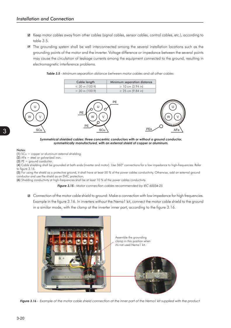
Table 3.5 - Minimum separation distance between motor cables and all other cables
Cable length Minimum separation distance
> 30 m (100 ft)
AFePEs
oooooo
oooooooooo
oooooooooooooooooooooooooooo
V
U
W
SCu
PE
PE
PE
U
VW
Connection of the motor cable shield to ground: Make a connection with low impedance for high frequencies.
Example in the figure 3.16. In inverters without the Nema1 kit, connect the motor cable shield to the ground
in a similar mode, with the clamp at the inverter inner part, according to the figure 3.16.
Figure 3.16 - Example of the motor cable shield connection at the inner part of the Nema1 kit supplied with the product
Notes:(1) SCu = copper or aluminum external shielding.(2) AFe = steel or galvanized iron.(3) PE = ground conductor.(4) Cable shielding shall be grounded at both ends (inverter and motor). Use 360º connections for a low impedance to high-frequencies. Referto figure 3.16.(5) For using the shield as a protective ground, it shall have at least 50 % of the power cables conductivity. Otherwise, add an external ground conductor and use the shield as an EMC protection.(6) Shielding conductivity at high-frequencies shall be at least 10 % of the power cables conductivity.
Figure 3.15
Assemble the grounding clamp in this position when it's not used Nema1 kit.
Installation and Connection
3-21
3
3.2.4 Grounding Connections
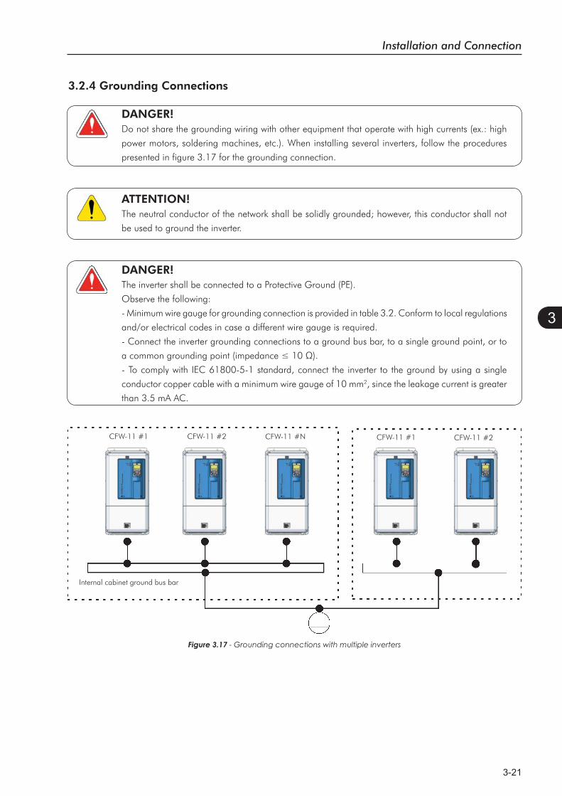
DANGER!Do not share the grounding wiring with other equipment that operate with high currents (ex.: high
power motors, soldering machines, etc.). When installing several inverters, follow the procedures
presented in figure 3.17 for the grounding connection.
ATTENTION!The neutral conductor of the network shall be solidly grounded; however, this conductor shall not
be used to ground the inverter.
DANGER!The inverter shall be connected to a Protective Ground (PE).
Observe the following:
- Minimum wire gauge for grounding connection is provided in table 3.2. Conform to local regulations
and/or electrical codes in case a different wire gauge is required.
- Connect the inverter grounding connections to a ground bus bar, to a single ground point, or to
- To comply with IEC 61800-5-1 standard, connect the inverter to the ground by using a single
conductor copper cable with a minimum wire gauge of 10 mm2, since the leakage current is greater
than 3.5 mA AC.
Figure 3.17 - Grounding connections with multiple inverters
Internal cabinet ground bus bar
CFW-11 #1 CFW-11 #2 CFW-11 #N CFW-11 #2CFW-11 #1

Installation and Connection
3-22
3
Figure 3.18 (a) - Signals at connector XC1 - Digital inputs working as 'Active High'
Connector XC1 Factory Default Function Specifications
1 +REFPositive reference for potentiometer
Output voltage:+5.4 V, ±5 %. Maximum output current: 2 mA
2 AI1+Analog input #1:Speed reference (remote)
DifferentialResolution: 12 bitsSignal: 0 to 10 V (RIN IN
Maximum voltage: ±30 V3 AI1-
4 REF-Negative reference for potentiometer
Output voltage: -4.7 V, ±5 %. Maximum output current: 2 mA
5 AI2+Analog input #2:No function
DifferentialResolution: 11 bits + signalSignal: 0 to ±10 V (RIN IN
Maximum voltage: ±30 V6 AI2-
7 AO1
Analog output #1:Speed
Galvanic IsolationResolution: 11 bitsSignal: 0 to 10 V (RL L
Protected against short-circuit.
8AGND (24 V)
Reference (0 V) for the analog outputs parallel with a 22 nF capacitor.
9 AO2
Analog output #2:Motor current
Galvanic IsolationResolution: 11 bitsSignal: 0 to 10 V (RL L
Protected against short-circuit.
10AGND (24 V)
Reference (0 V) for the analog outputs parallel with a 22 nF capacitor.
11 DGND*Reference (0 V) for the 24 Vdc power supply parallel with a 22 nF capacitor.
12 COMCommon point of the digital inputs
13 24 Vdc
24 Vdc power supply 24 Vdc power supply, ±8 %. Capacity: 500 mA.Note: In the models with the 24 Vdc external control power supply (CFW11XXXXXXOW) the terminal 13 of XC1 becomes an input, i.e., the user must connect a 24 V power supply for the inverter (refer to the section 7.1.4 for more details). In all the other models this terminal is an output, i.e., the user has a 24 Vdc power supply available there.
14 COMCommon point of the digital inputs
15 DI1Digital input #1:Start / Stop
6 isolated digital inputs
Maximum input voltage = 30 VInput current: 11 mA @ 24 Vdc
16 DI2Digital input #2:Direction of rotation (remote)
17 DI3Digital input #3:No function
18 DI4Digital input #4:No function
19 DI5Digital input #5:Jog (remote)
20 DI6Digital input #6:2nf ramp
21 NC1 Digital output #1 DO1 (RL1): No fault
Contact rating:Maximum voltage: 240 VacMaximum current: 1 ANC - Normally closed contact;C - Common;NO - Normally open contact.
22 C123 NO124 NC2 Digital output #2 DO2 (RL2):
N > NX - Speed > P028825 C226 NO227 NC3 Digital output #3 DO3 (RL3):
N* > NX - Speed reference > P0288
28 C329 NO3
CCW
CW
rpm
amp
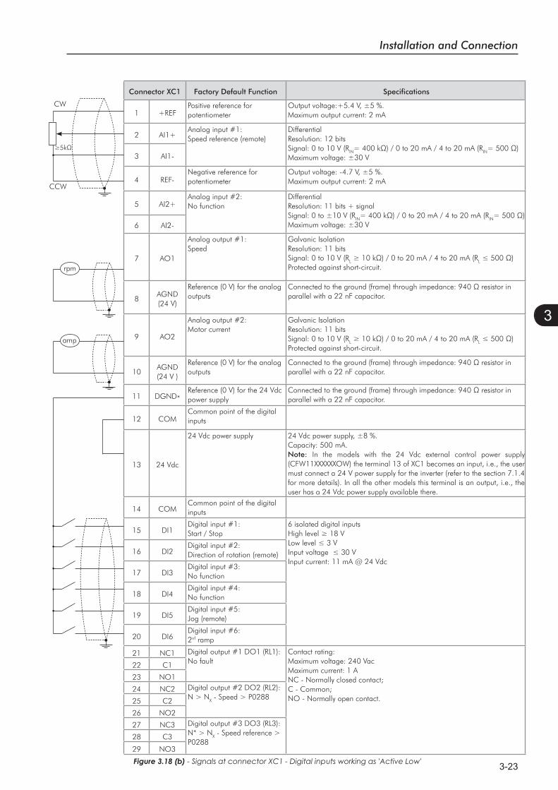
3.2.5 Control ConnectionsThe control connections (analog inputs/outputs, digital inputs/outputs), shall be performed in connector XC1
of the CC11 control board.
Functions and typical connections are presented in figures 3.18 (a) and (b).
Installation and Connection
3-23
3
Figure 3.18 (b) - Signals at connector XC1 - Digital inputs working as 'Active Low'
Connector XC1 Factory Default Function Specifications
1 +REFPositive reference for potentiometer
Output voltage:+5.4 V, ±5 %. Maximum output current: 2 mA
2 AI1+Analog input #1:Speed reference (remote)
DifferentialResolution: 12 bitsSignal: 0 to 10 V (RIN IN
Maximum voltage: ±30 V3 AI1-
4 REF-Negative reference for potentiometer
Output voltage: -4.7 V, ±5 %. Maximum output current: 2 mA
5 AI2+Analog input #2:No function
DifferentialResolution: 11 bits + signalSignal: 0 to ±10 V (RIN IN
Maximum voltage: ±30 V6 AI2-
7 AO1
Analog output #1:Speed
Galvanic IsolationResolution: 11 bitsSignal: 0 to 10 V (RL L
Protected against short-circuit.
8AGND (24 V)
Reference (0 V) for the analog outputs parallel with a 22 nF capacitor.
9 AO2
Analog output #2:Motor current
Galvanic IsolationResolution: 11 bitsSignal: 0 to 10 V (RL L
Protected against short-circuit.
10AGND (24 V )
Reference (0 V) for the analog outputs parallel with a 22 nF capacitor.
11 DGND*Reference (0 V) for the 24 Vdc power supply parallel with a 22 nF capacitor.
12 COMCommon point of the digital inputs
13 24 Vdc
24 Vdc power supply 24 Vdc power supply, ±8 %. Capacity: 500 mA.Note: In the models with the 24 Vdc external control power supply (CFW11XXXXXXOW) the terminal 13 of XC1 becomes an input, i.e., the user must connect a 24 V power supply for the inverter (refer to the section 7.1.4 for more details). In all the other models this terminal is an output, i.e., the user has a 24 Vdc power supply available there.
14 COMCommon point of the digital inputs
15 DI1Digital input #1:Start / Stop
6 isolated digital inputs
Input current: 11 mA @ 24 Vdc16 DI2
Digital input #2:Direction of rotation (remote)
17 DI3Digital input #3:No function
18 DI4Digital input #4:No function
19 DI5Digital input #5:Jog (remote)
20 DI6Digital input #6:2nf ramp
21 NC1 Digital output #1 DO1 (RL1): No fault
Contact rating:Maximum voltage: 240 VacMaximum current: 1 ANC - Normally closed contact;C - Common;NO - Normally open contact.
22 C1
23 NO1
24 NC2 Digital output #2 DO2 (RL2): N > NX - Speed > P028825 C2
26 NO2
27 NC3 Digital output #3 DO3 (RL3): N* > NX - Speed reference > P0288
28 C3
29 NO3
CCW
CW
rpm
amp

Installation and Connection
3-24
3
The analog inputs and outputs are factory set to operate in the range from 0 to 10 V; this setting may be
changed by using DIP-switch S1.
Figure 3.19 - Connector XC1 and DIP-switches for selecting the signal type of the analog inputs and outputs
Signal Factory Default Function DIP-switch Selection Factory Setting
AI1 Speed Reference (remote) S1.4OFF: 0 to 10 V (factory setting)ON: 4 to 20 mA / 0 to 20 mA
OFF
AI2 No Function S1.3OFF: 0 to ±10 V (factory setting)ON: 4 to 20 mA / 0 to 20 mA
OFF
AO1 Speed S1.2OFF: 4 to 20 mA / 0 to 20 mAON: 0 to 10 V (factory setting)
ON
AO2 Motor Current S1.1OFF: 4 to 20 mA / 0 to 20 mAON: 0 to 10 V (factory setting)
ON
Parameters related to the analog inputs and outputs (AI1, AI2, AO1, and AO2) shall be programmed according
to the DIP-switches settings and desired values.
Follow instructions below for the proper installation of the control wiring:
1) Wire gauge: 0.5 mm² (20 AWG) to 1.5 mm² (14 AWG);
2) Maximum tightening torque: 0.50 N.m (4.50 lbf.in);
3) Use shielded cables for the connections in XC1 and run the cables separated from the remaining circuits
(power, 110 V / 220 Vac control, etc.), as presented in table 3.7. If control wiring must cross other cables
(power cables for instance), make it cross perpendicular to the wiring and provide a minimum separation
of 5 cm (1.9 in) at the crossing point.
Slot 5
Slot 1 (white)
Slot 2 (yellow)
Slot 3 (green)
Slot 4
NOTE! Remove the jumper between XC1:11 and 12 and install it between XC1:12 and 13 to use the digital
inputs as 'Active Low'.
Table 3.6
Installation and Connection
3-25
3
Table 3.7 - Minimum separation distances between wiring
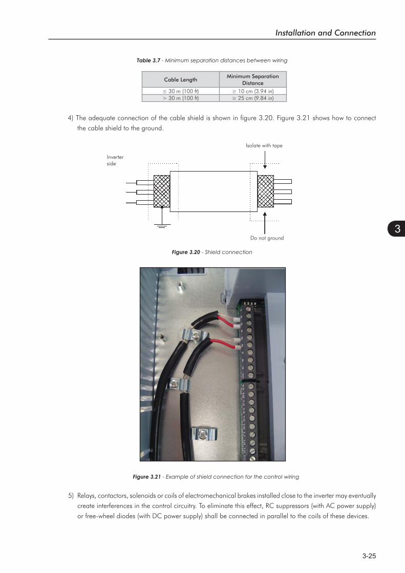
4) The adequate connection of the cable shield is shown in figure 3.20. Figure 3.21 shows how to connect
the cable shield to the ground.
Figure 3.20 - Shield connection
5) Relays, contactors, solenoids or coils of electromechanical brakes installed close to the inverter may eventually
create interferences in the control circuitry. To eliminate this effect, RC suppressors (with AC power supply)
or free-wheel diodes (with DC power supply) shall be connected in parallel to the coils of these devices.
Do not ground
Inverterside
Isolate with tape
Figure 3.21 - Example of shield connection for the control wiring
Cable LengthMinimum Separation
Distance
> 30 m (100 ft)
Installation and Connection
3-26
3
Start/Stop
Connector XC1
1 + REF
2 AI1+
3 AI1-
4 - REF
5 AI2+
6 AI2-
7 AO1
8 AGND (24 V)
9 AO2
10 AGND (24 V)
11 DGND*
12 COM
13 24 Vdc
14 COM
15 DI1
16 DI2
17 DI3
18 DI4
19 DI5
20 DI6
21 NC1DO1(RL1)
22 C1
23 NO1
24 NC2DO2(RL2)
25 C2
26 NO2
27 NC3DO3(RL3)
28 C3
29 NO3
Jog
Direction of Rotation
AH
H
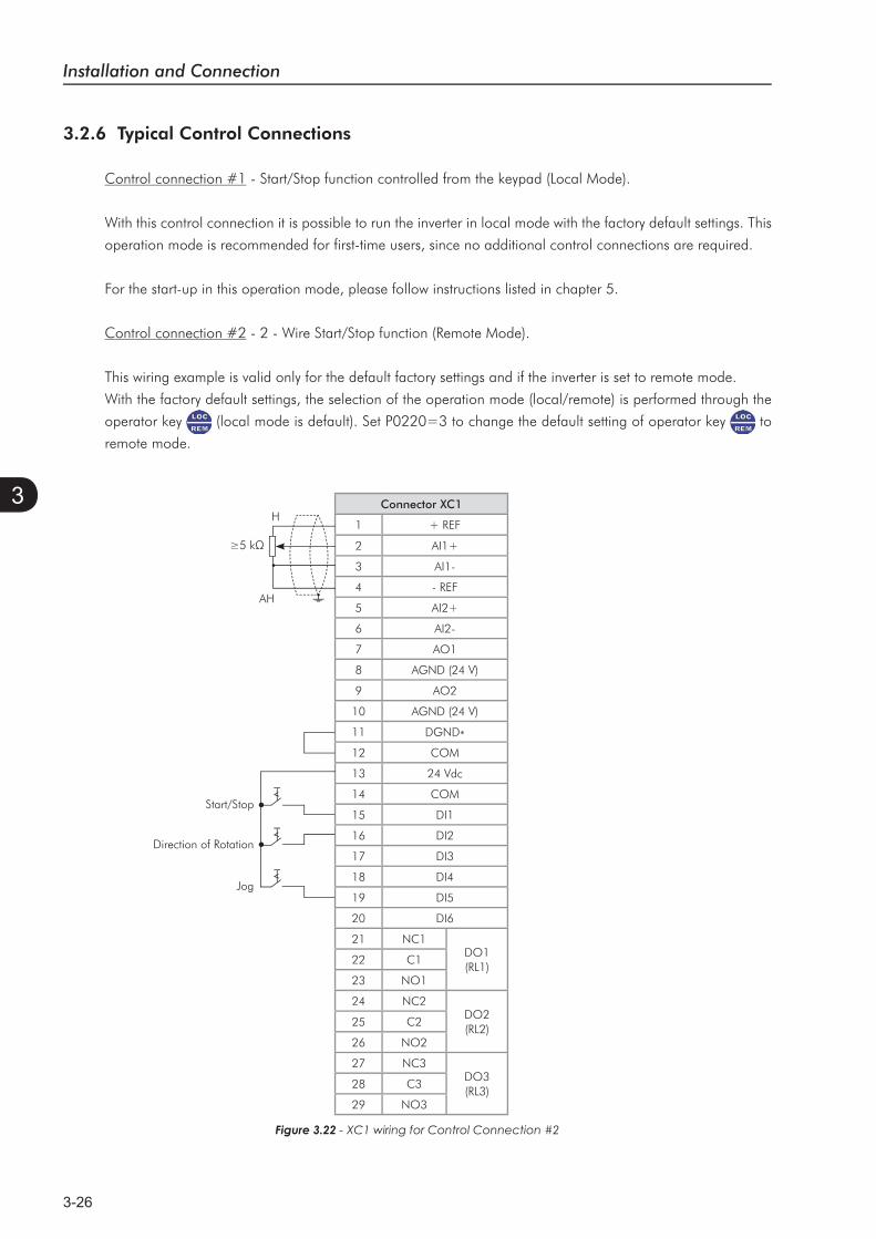
Figure 3.22 - XC1 wiring for Control Connection #2
3.2.6 Typical Control Connections
Control connection #1 - Start/Stop function controlled from the keypad (Local Mode).
With this control connection it is possible to run the inverter in local mode with the factory default settings. This
operation mode is recommended for first-time users, since no additional control connections are required.
For the start-up in this operation mode, please follow instructions listed in chapter 5.
Control connection #2 - 2 - Wire Start/Stop function (Remote Mode).
This wiring example is valid only for the default factory settings and if the inverter is set to remote mode.
With the factory default settings, the selection of the operation mode (local/remote) is performed through the
operator key (local mode is default). Set P0220=3 to change the default setting of operator key to
remote mode.
Installation and Connection
3-27
3
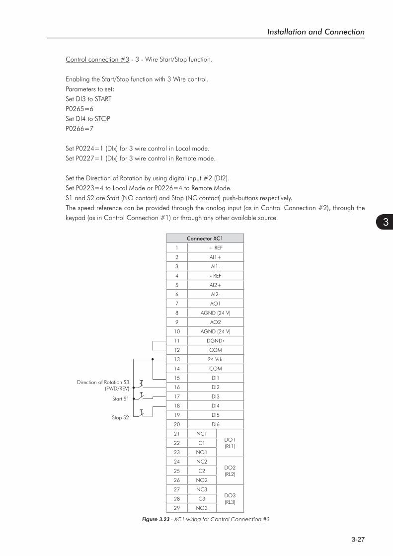
Control connection #3 - 3 - Wire Start/Stop function.
Enabling the Start/Stop function with 3 Wire control.
Parameters to set:
Set DI3 to START
P0265=6
Set DI4 to STOP
P0266=7
Set P0224=1 (DIx) for 3 wire control in Local mode.
Set P0227=1 (DIx) for 3 wire control in Remote mode.
Set the Direction of Rotation by using digital input #2 (DI2).
Set P0223=4 to Local Mode or P0226=4 to Remote Mode.
S1 and S2 are Start (NO contact) and Stop (NC contact) push-buttons respectively.
The speed reference can be provided through the analog input (as in Control Connection #2), through the
keypad (as in Control Connection #1) or through any other available source.
Figure 3.23
Direction of Rotation S3(FWD/REV)
Stop S2
Start S1
Connector XC1
1 + REF
2 AI1+
3 AI1-
4 - REF
5 AI2+
6 AI2-
7 AO1
8 AGND (24 V)
9 AO2
10 AGND (24 V)
11 DGND*
12 COM
13 24 Vdc
14 COM
15 DI1
16 DI2
17 DI3
18 DI4
19 DI5
20 DI6
21 NC1DO1(RL1)
22 C1
23 NO1
24 NC2DO2(RL2)
25 C2
26 NO2
27 NC3DO3(RL3)
28 C3
29 NO3
Installation and Connection
3-28
3
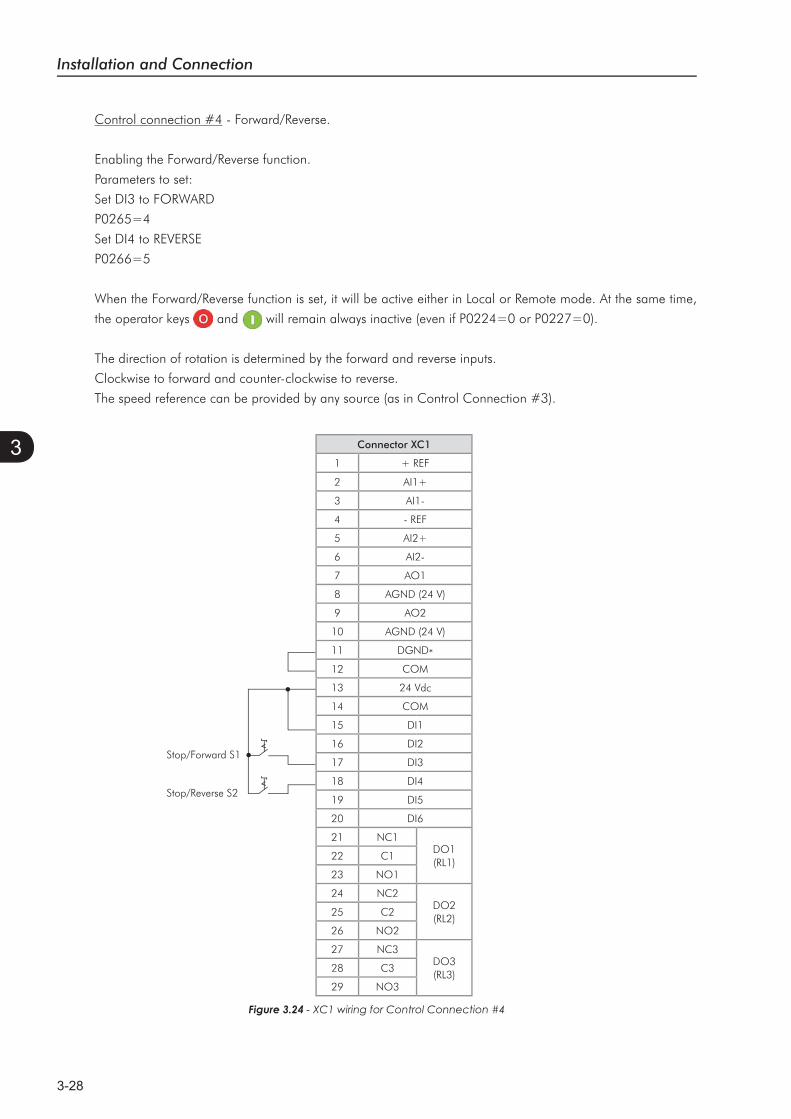
Control connection #4 - Forward/Reverse.
Enabling the Forward/Reverse function.
Parameters to set:
Set DI3 to FORWARD
P0265=4
Set DI4 to REVERSE
P0266=5
When the Forward/Reverse function is set, it will be active either in Local or Remote mode. At the same time,
the operator keys and will remain always inactive (even if P0224=0 or P0227=0).
The direction of rotation is determined by the forward and reverse inputs.
Clockwise to forward and counter-clockwise to reverse.
The speed reference can be provided by any source (as in Control Connection #3).
Stop/Forward S1
Stop/Reverse S2
Figure 3.24 - XC1 wiring for Control Connection #4
Connector XC1
1 + REF
2 AI1+
3 AI1-
4 - REF
5 AI2+
6 AI2-
7 AO1
8 AGND (24 V)
9 AO2
10 AGND (24 V)
11 DGND*
12 COM
13 24 Vdc
14 COM
15 DI1
16 DI2
17 DI3
18 DI4
19 DI5
20 DI6
21 NC1DO1(RL1)
22 C1
23 NO1
24 NC2DO2(RL2)
25 C2
26 NO2
27 NC3DO3(RL3)
28 C3
29 NO3
Installation and Connection
3-29
3
3.3 INSTALLATION ACCORDING TO THE EUROPEAN DIRECTIVE OF ELECTROMAGNETIC COMPATIBILITY
The frame size E CFW-11 inverters have an internal RFI filter for the reduction of the electromagnetic interference.
These inverters, when properly installed, meet the requirements of the electromagnetic compatibility directive
– ‘’EMC Directive 2004/108/EC’’.
The CFW-11 inverter series has been designed only for industrial applications. Therefore, the emission limits of
harmonic currents defined by the standards EN 61000-3-2 and EN 61000-3-2/A14 are not applicable.
ATTENTION!Do not use inverters with internal RFI filters in IT networks (neutral is not grounded or grounding
provided by a high ohm value resistor) or in grounded delta networks (“delta corner earthed”), because
these type of networks damage the filter capacitors of the inverter.
3.3.1 Conformal Installation
For the conformal installation use:
1. J1 cable in the position (XE1). Refer to item 3.2.3.1.1.
2. a) Shielded output cables (motor cables) and connect the shield at both ends (motor and inverter) with a
low impedance connection for high frequency. Use the clamp supplied with the product. Make sure there
is a good contact between the cable shield and the clamp. Refer to the figure 3.16 as an example. The
required cable separation is presented in table 3.5. For further information, please refer to item 3.2.3.
Maximum motor cable length and conduced and radiated emission levels according to the table 3.9. If
a lower conducted emission level (category C2) is wished, then an external RFI filter must be used at the
inverter input. For more information (RFI filter commercial reference, motor cable length and emission
levels) refer to the table 3.9.
b) As a second option only for the V/f and VVW control modes when using a sinusoidal output filter:
Adjust the switching frequency in 5 or 10 kHz (P0297=2 or 3) and the parameter P0350 in 2 or 3 (not
allowing the automatic reduction of the switching frequency to 2.5 kHz). Refer to tables 8.2 to 8.5 for
output current specification for 5 kHz and 10 kHz. Output cables (motor cables) that are not shielded can
be used, provided that RFI filters are installed at the inverter input and output, as presented in the table
3.10. The maximum motor cable length and the emission levels for each configuration are also presented.
Keep the separation from the other cables according to the table 3.5. Refer to the section 3.2.3 for more
information. The filters presented in table 3.10 were defined for the operation of the inverter at 5 kHz
switching frequency and rated output current as shown in tables 8.2 and 8.3. Those filters can also be
used for 10 kHz, however they are not optimized for it. In order to optimize them for use with the inverter
at 10 kHz, refer to the tables 8.4 and 8.5.
3. Use shielded control cables, keeping them separate from the other cables as described in item 3.2.5.
4. Inverter grounding according to the instructions on item 3.2.4.
Installation and Connection
3-30
3
3.3.2 Standard Definitions
IEC/EN 61800-3: “Adjustable Speed Electrical Power Drives Systems”
- Environment:
First Environment: includes domestic premises. It also includes establishments directly connected without
intermediate transformer to a low-voltage power supply network which supplies buildings used for domestic
purposes.
Example: houses, apartments, commercial installations, or offices located in residential buildings.
Second Environment: includes all establishments other than those directly connected to a low-voltage power
supply network which supplies buildings used for domestic purposes.
Example: industrial area, technical area of any building supplied by a dedicated transformer.
- Categories:
Category C1: inverters with a voltage rating less than 1000 V and intended for use in the First Environment.
Category C2: inverters with a voltage rating less than 1000 V, intended for use in the First Environment,
not provided with a plug connector or a movable installations, and installed and commissioned by a
professional.
Note: A professional is a person or organization familiar with the installation and/or commissioning of inverters,
including the EMC aspects.
Category C3: inverters with a voltage rating less than 1000 V and intended for use in the Second Environment
only (not designed for use in the First Environment).
Category C4: inverters with a voltage rating equal to or greater than 1000 V, or with a current rating equal to
or greater than 400 Amps, or intended for use in complex systems in the Second Environment.
EN 55011: “Threshold values and measuring methods for radio interference from industrial,
scientific and medical (ISM) high-frequency equipment”
Class B: equipment intended for use in the low-voltage power supply network (residential, commercial, and
light-industrial environments).
Class A1: equipment intended for use in the low-voltage power supply network. Restricted distribution.
Note: Must be installed and commissioned by a professional when applied in the low-voltage power supply
network.
Class A2: equipment intended for use in industrial environments.
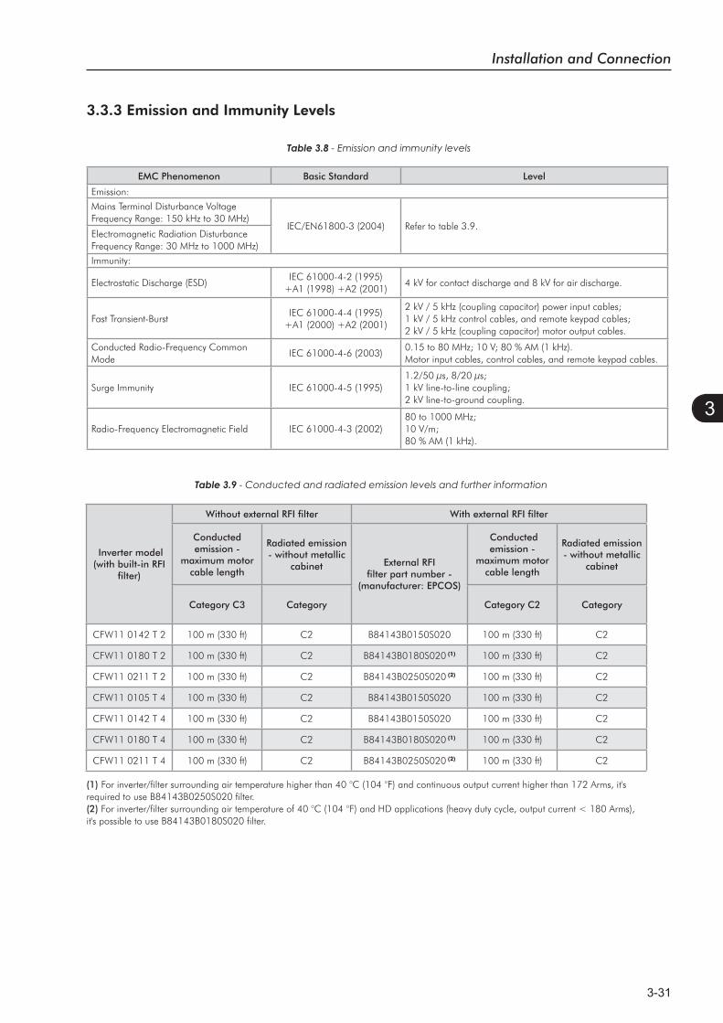
Installation and Connection
3-31
3
Table 3.9 - Conducted and radiated emission levels and further information
Inverter model (with built-in RFI
filter)
Without external RFI filter With external RFI filter
Conductedemission -
maximum motor cable length
Radiated emission - without metallic
cabinet External RFI filter part number -
(manufacturer: EPCOS)
Conducted emission -
maximum motor cable length
Radiated emission - without metallic
cabinet
Category C3 Category Category C2 Category
CFW11 0142 T 2 100 m (330 ft) C2 B84143B0150S020 100 m (330 ft) C2
CFW11 0180 T 2 100 m (330 ft) C2 B84143B0180S020 (1) 100 m (330 ft) C2
CFW11 0211 T 2 100 m (330 ft) C2 B84143B0250S020 (2) 100 m (330 ft) C2
CFW11 0105 T 4 100 m (330 ft) C2 B84143B0150S020 100 m (330 ft) C2
CFW11 0142 T 4 100 m (330 ft) C2 B84143B0150S020 100 m (330 ft) C2
CFW11 0180 T 4 100 m (330 ft) C2 B84143B0180S020 (1) 100 m (330 ft) C2
CFW11 0211 T 4 100 m (330 ft) C2 B84143B0250S020 (2) 100 m (330 ft) C2
(1) For inverter/filter surrounding air temperature higher than 40 °C (104 °F) and continuous output current higher than 172 Arms, it's required to use B84143B0250S020 filter.(2) For inverter/filter surrounding air temperature of 40 °C (104 °F) and HD applications (heavy duty cycle, output current < 180 Arms), it's possible to use B84143B0180S020 filter.
3.3.3 Emission and Immunity Levels
Table 3.8 - Emission and immunity levels
EMC Phenomenon Basic Standard Level
Emission:
Mains Terminal Disturbance VoltageFrequency Range: 150 kHz to 30 MHz)
IEC/EN61800-3 (2004) Refer to table 3.9.Electromagnetic Radiation DisturbanceFrequency Range: 30 MHz to 1000 MHz)
Immunity:
Electrostatic Discharge (ESD)IEC 61000-4-2 (1995)
+A1 (1998) +A2 (2001)4 kV for contact discharge and 8 kV for air discharge.
Fast Transient-BurstIEC 61000-4-4 (1995)
+A1 (2000) +A2 (2001)
2 kV / 5 kHz (coupling capacitor) power input cables;1 kV / 5 kHz control cables, and remote keypad cables; 2 kV / 5 kHz (coupling capacitor) motor output cables.
Conducted Radio-Frequency Common Mode
IEC 61000-4-6 (2003)0.15 to 80 MHz; 10 V; 80 % AM (1 kHz).Motor input cables, control cables, and remote keypad cables.
Surge Immunity IEC 61000-4-5 (1995)1.2/50 μs, 8/20 μs; 1 kV line-to-line coupling; 2 kV line-to-ground coupling.
Radio-Frequency Electromagnetic Field IEC 61000-4-3 (2002)80 to 1000 MHz; 10 V/m;80 % AM (1 kHz).
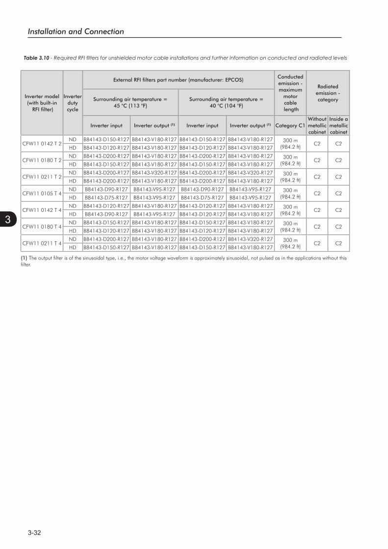
Installation and Connection
3-32
3
Table 3.10
(1) The output filter is of the sinusoidal type, i.e., the motor voltage waveform is approximately sinusoidal, not pulsed as in the applications without this filter.
Inverter model (with built-in
RFI filter)
Inverterdutycycle
External RFI filters part number (manufacturer: EPCOS) Conductedemission - maximum
motor cable
length
Radiated emission - categorySurrounding air temperature =
45 °C (113 °F)Surrounding air temperature =
40 °C (104 °F)
Inverter input Inverter output (1) Inverter input Inverter output (1) Category C1 Withoutmetalliccabinet
Inside a metalliccabinet
CFW11 0142 T 2ND B84143-D150-R127 B84143-V180-R127 B84143-D150-R127 B84143-V180-R127 300 m
(984.2 ft)C2 C2
HD B84143-D120-R127 B84143-V180-R127 B84143-D120-R127 B84143-V180-R127
CFW11 0180 T 2ND B84143-D200-R127 B84143-V180-R127 B84143-D200-R127 B84143-V180-R127 300 m
(984.2 ft)C2 C2
HD B84143-D150-R127 B84143-V180-R127 B84143-D150-R127 B84143-V180-R127
CFW11 0211 T 2ND B84143-D200-R127 B84143-V320-R127 B84143-D200-R127 B84143-V320-R127 300 m
(984.2 ft)C2 C2
HD B84143-D200-R127 B84143-V180-R127 B84143-D200-R127 B84143-V180-R127
CFW11 0105 T 4ND B84143-D90-R127 B84143-V95-R127 B84143-D90-R127 B84143-V95-R127 300 m
(984.2 ft)C2 C2
HD B84143-D75-R127 B84143-V95-R127 B84143-D75-R127 B84143-V95-R127
CFW11 0142 T 4ND B84143-D120-R127 B84143-V180-R127 B84143-D120-R127 B84143-V180-R127 300 m
(984.2 ft)C2 C2
HD B84143-D90-R127 B84143-V95-R127 B84143-D120-R127 B84143-V180-R127
CFW11 0180 T 4ND B84143-D150-R127 B84143-V180-R127 B84143-D150-R127 B84143-V180-R127 300 m
(984.2 ft)C2 C2
HD B84143-D120-R127 B84143-V180-R127 B84143-D120-R127 B84143-V180-R127
CFW11 0211 T 4ND B84143-D200-R127 B84143-V180-R127 B84143-D200-R127 B84143-V320-R127 300 m
(984.2 ft)C2 C2
HD B84143-D150-R127 B84143-V180-R127 B84143-D150-R127 B84143-V180-R127
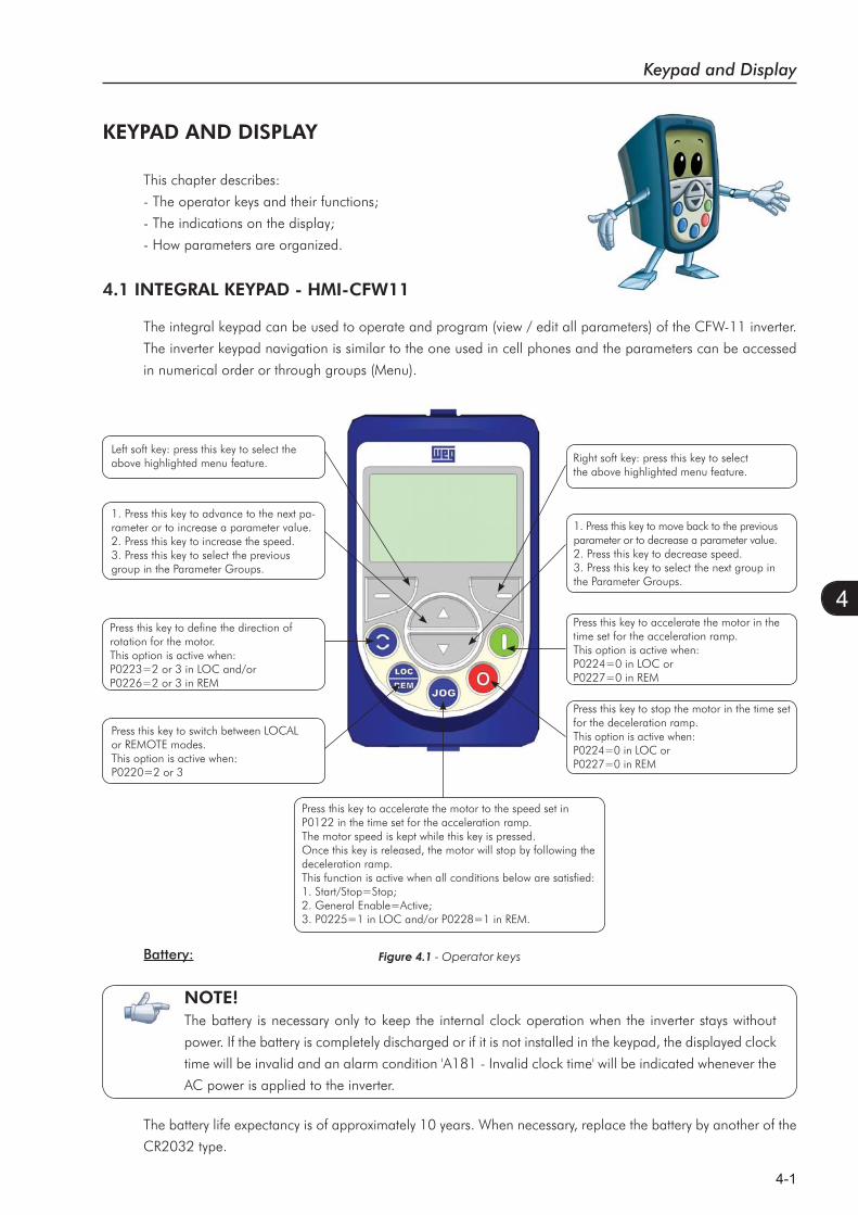
Keypad and Display
4-1
4
KEYPAD AND DISPLAY
This chapter describes:
- The operator keys and their functions;
- The indications on the display;
- How parameters are organized.
4.1 INTEGRAL KEYPAD - HMI-CFW11
The integral keypad can be used to operate and program (view / edit all parameters) of the CFW-11 inverter.
The inverter keypad navigation is similar to the one used in cell phones and the parameters can be accessed
in numerical order or through groups (Menu).
Left soft key: press this key to select the above highlighted menu feature.
1. Press this key to advance to the next pa-rameter or to increase a parameter value.2. Press this key to increase the speed.3. Press this key to select the previous group in the Parameter Groups.
Press this key to define the direction of rotation for the motor.This option is active when:P0223=2 or 3 in LOC and/orP0226=2 or 3 in REM
Press this key to switch between LOCAL or REMOTE modes.This option is active when:P0220=2 or 3
Press this key to accelerate the motor to the speed set in P0122 in the time set for the acceleration ramp.The motor speed is kept while this key is pressed.Once this key is released, the motor will stop by following the deceleration ramp.This function is active when all conditions below are satisfied: 1. Start/Stop=Stop;2. General Enable=Active;3. P0225=1 in LOC and/or P0228=1 in REM.
Press this key to stop the motor in the time set for the deceleration ramp.This option is active when:P0224=0 in LOC orP0227=0 in REM
Press this key to accelerate the motor in the time set for the acceleration ramp.This option is active when:P0224=0 in LOC or P0227=0 in REM
1. Press this key to move back to the previous parameter or to decrease a parameter value.2. Press this key to decrease speed.3. Press this key to select the next group in the Parameter Groups.
Right soft key: press this key to select the above highlighted menu feature.
Figure 4.1 - Operator keysBattery:
The battery life expectancy is of approximately 10 years. When necessary, replace the battery by another of the
CR2032 type.
NOTE!The battery is necessary only to keep the internal clock operation when the inverter stays without
power. If the battery is completely discharged or if it is not installed in the keypad, the displayed clock
time will be invalid and an alarm condition 'A181 - Invalid clock time' will be indicated whenever the
AC power is applied to the inverter.
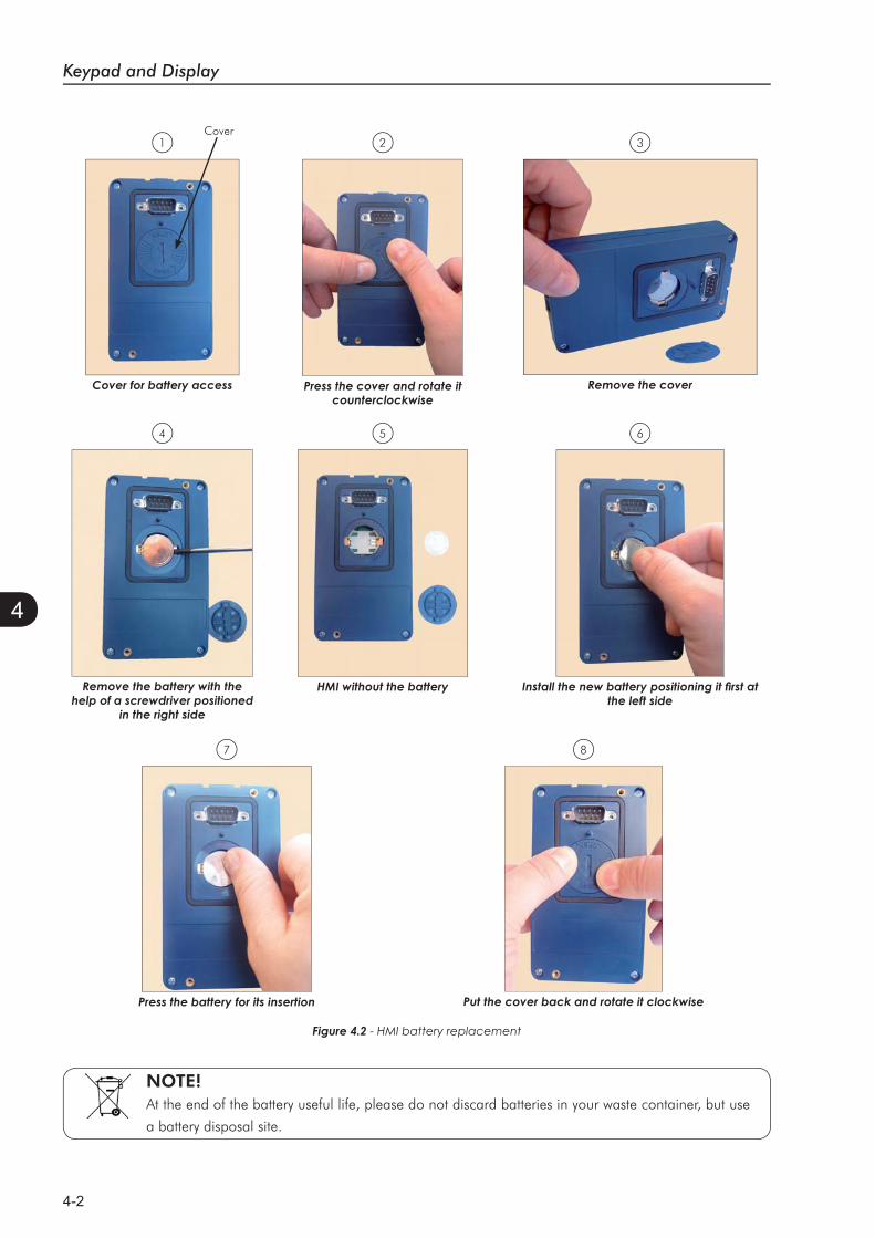
Keypad and Display
4-2
4
1 2 3
4 5 6
7 8
NOTE!At the end of the battery useful life, please do not discard batteries in your waste container, but use
a battery disposal site.
Figure 4.2 - HMI battery replacement
Cover
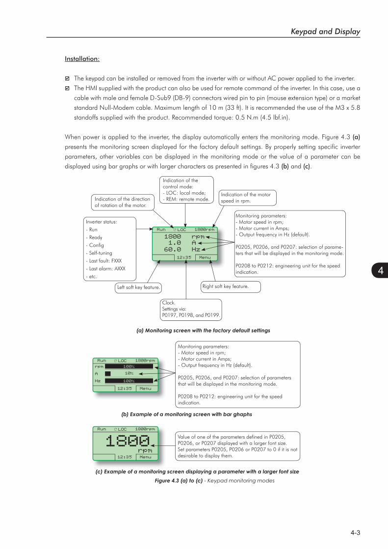
Keypad and Display
4-3
4
Run LOC 1800rpm
12:35 Menu
1800 rpm 1.0 A60.0 Hz
Installation:
The keypad can be installed or removed from the inverter with or without AC power applied to the inverter.
The HMI supplied with the product can also be used for remote command of the inverter. In this case, use a
cable with male and female D-Sub9 (DB-9) connectors wired pin to pin (mouse extension type) or a market
standard Null-Modem cable. Maximum length of 10 m (33 ft). It is recommended the use of the M3 x 5.8
standoffs supplied with the product. Recommended torque: 0.5 N.m (4.5 lbf.in).
When power is applied to the inverter, the display automatically enters the monitoring mode. Figure 4.3 (a)
presents the monitoring screen displayed for the factory default settings. By properly setting specific inverter
parameters, other variables can be displayed in the monitoring mode or the value of a parameter can be
displayed using bar graphs or with larger characters as presented in figures 4.3 (b) and (c).
Inverter status:
- Run
- Ready
- Config
- Self-tuning
- Last fault: FXXX
- Last alarm: AXXX
- etc.
Indication of the direction of rotation of the motor.
Indication of the control mode:- LOC: local mode;- REM: remote mode.
Indication of the motor speed in rpm.
Monitoring parameters:- Motor speed in rpm;- Motor current in Amps;- Output frequency in Hz (default).
P0205, P0206, and P0207: selection of parame-ters that will be displayed in the monitoring mode.
P0208 to P0212: engineering unit for the speed indication.
Right soft key feature.
Clock.Settings via: P0197, P0198, and P0199.
Left soft key feature.
- Keypad monitoring modes
Run LOC 1800rpm
12:35 Menu
rpm
A
Hz
Monitoring parameters:- Motor speed in rpm;- Motor current in Amps;- Output frequency in Hz (default).
P0205, P0206, and P0207: selection of parameters that will be displayed in the monitoring mode.
P0208 to P0212: engineering unit for the speed indication.
100%
10%
100%
Run LOC 1800rpm
12:35 Menu
1800Value of one of the parameters defined in P0205, P0206, or P0207 displayed with a larger font size.Set parameters P0205, P0206 or P0207 to 0 if it is not desirable to display them.
rpm
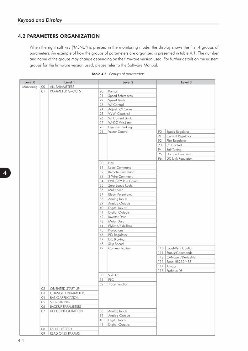
Keypad and Display
4-4
4
Table 4.1 - Groups of parameters
4.2 PARAMETERS ORGANIZATION
When the right soft key ("MENU") is pressed in the monitoring mode, the display shows the first 4 groups of parameters. An example of how the groups of parameters are organized is presented in table 4.1. The number and name of the groups may change depending on the firmware version used. For further details on the existent
groups for the firmware version used, please refer to the Software Manual.
Level 0 Level 1 Level 2 Level 3Monitoring 00 ALL PARAMETERS
01 PARAMETER GROUPS 20 Ramps21 Speed References22 Speed Limits23 V/f Control24 Adjust. V/f Curve25 VVW Control26 V/f Current Limit.27 V/f DC Volt.Limit.28 Dynamic Braking29 Vector Control 90 Speed Regulator
91 Current Regulator92 Flux Regulator93 I/F Control94 Self-Tuning95 Torque Curr.Limit.96 DC Link Regulator
30 HMI31 Local Command32 Remote Command33 3-Wire Command34 FWD/REV Run Comm.35 Zero Speed Logic36 Multispeed37 Electr. Potentiom.38 Analog Inputs39 Analog Outputs40 Digital Inputs41 Digital Outputs42 Inverter Data43 Motor Data44 FlyStart/RideThru45 Protections46 PID Regulator47 DC Braking48 Skip Speed49 Communication 110 Local/Rem Config.
111 Status/Commands112 CANopen/DeviceNet113 Serial RS232/485114 Anybus115 Profibus DP
50 SoftPLC51 PLC52 Trace Function
02 ORIENTED START-UP03 CHANGED PARAMETERS04 BASIC APPLICATION05 SELF-TUNING06 BACKUP PARAMETERS07 I/O CONFIGURATION 38 Analog Inputs
39 Analog Outputs40 Digital Inputs41 Digital Outputs
08 FAULT HISTORY09 READ ONLY PARAMS.
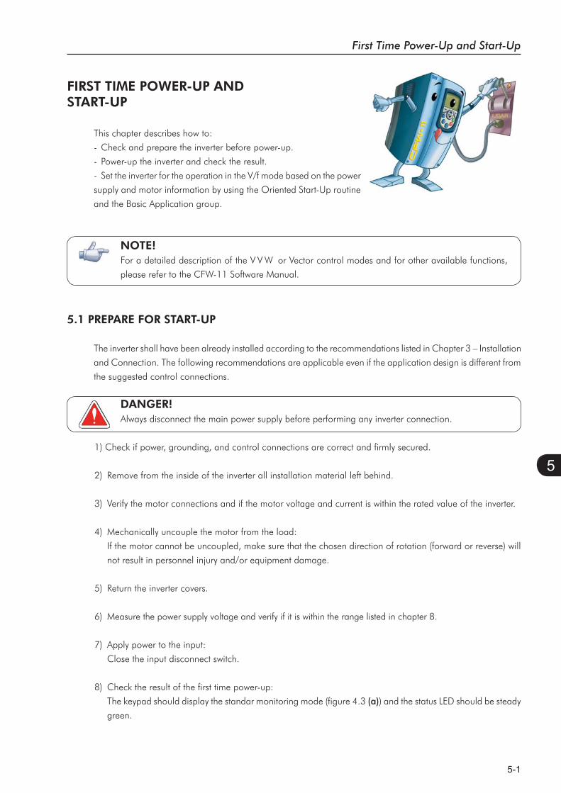
First Time Power-Up and Start-Up
5-1
5
FIRST TIME POWER-UP ANDSTART-UP
This chapter describes how to:
- Check and prepare the inverter before power-up.
- Power-up the inverter and check the result.
- Set the inverter for the operation in the V/f mode based on the power
supply and motor information by using the Oriented Start-Up routine
and the Basic Application group.
NOTE!For a detailed description of the V V W or Vector control modes and for other available functions,
please refer to the CFW-11 Software Manual.
5.1 PREPARE FOR START-UP
The inverter shall have been already installed according to the recommendations listed in Chapter 3 – Installation
and Connection. The following recommendations are applicable even if the application design is different from
the suggested control connections.
DANGER!Always disconnect the main power supply before performing any inverter connection.
1) Check if power, grounding, and control connections are correct and firmly secured.
2) Remove from the inside of the inverter all installation material left behind.
3) Verify the motor connections and if the motor voltage and current is within the rated value of the inverter.
4) Mechanically uncouple the motor from the load:
If the motor cannot be uncoupled, make sure that the chosen direction of rotation (forward or reverse) will
not result in personnel injury and/or equipment damage.
5) Return the inverter covers.
6) Measure the power supply voltage and verify if it is within the range listed in chapter 8.
7) Apply power to the input:
Close the input disconnect switch.
8) Check the result of the first time power-up:
The keypad should display the standar monitoring mode (figure 4.3 (a)) and the status LED should be steady
green.
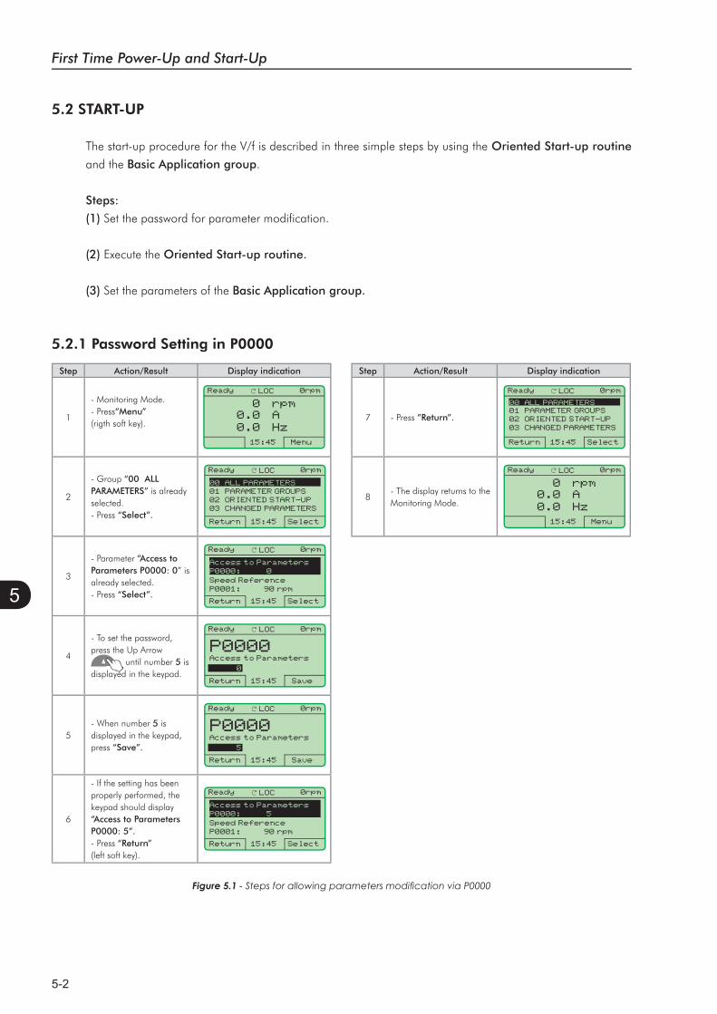
First Time Power-Up and Start-Up
5-2
5
5.2 START-UP
The start-up procedure for the V/f is described in three simple steps by using the Oriented Start-up routine
and the Basic Application group.
Steps:
(1) Set the password for parameter modification.
(2) Execute the Oriented Start-up routine.
(3) Set the parameters of the Basic Application group.
5.2.1 Password Setting in P0000
Step Action/Result Display indication
1
- Monitoring Mode.- Press“Menu”(rigth soft key).
Ready LOC 0rpm
15:45 Menu
0 rpm0.0 A0.0 Hz
2
- Group “00 ALL PARAMETERS” is already selected.- Press “Select”.
Ready LOC 0rpm
Return 15:45 Select
00 ALL PARAMETERS01 PARAMETER GROUPS 02 ORIENTED START-UP03 CHANGED PARAMETERS
3
- Parameter “Access to Parameters P0000: 0” is already selected.- Press “Select”.
Ready LOC 0rpm
Return 15:45 Select
Access to ParametersP0000: 0
Speed ReferenceP0001: 90 rpm
4
- To set the password, press the Up Arrow
until number 5 is displayed in the keypad.
Ready LOC 0rpm
Return 15:45 Save
P0000Access to Parameters
0
5- When number 5 is displayed in the keypad, press “Save”.
Ready LOC 0rpm
Return 15:45 Save
P0000Access to Parameters
5
6
- If the setting has been properly performed, the keypad should display “Access to Parameters P0000: 5”.- Press “Return” (left soft key).
Ready LOC 0rpm
Return 15:45 Select
Access to ParametersP0000: 5
Speed ReferenceP0001: 90 rpm
Step Action/Result Display indication
7 - Press ”Return”.
Ready LOC 0rpm
Return 15:45 Select
00 ALL PARAMETERS01 PARAMETER GROUPS 02 ORIENTED START-UP03 CHANGED PARAMETERS
8- The display returns to the Monitoring Mode.
Ready LOC 0rpm
15:45 Menu
0 rpm0.0 A0.0 Hz
Figure 5.1

First Time Power-Up and Start-Up
5-3
5
5.2.2 Oriented Start-Up
There is a group of parameters named ”Oriented Start-up” that makes the inverter settings easier. Inside this
group, there is a parameter – P0317 – that shall be set to enter into the Oriented Start-up routine.
The Oriented Start-up routine allows you to quickly set up the inverter for operation with the line and motor
used. This routine prompts you for the most commonly used parameters in a logic sequence.
In order to enter into the Oriented Start-up routine, follow the steps presented in figure 5.2, first modifying
parameter P0317 to 1 and then, setting all remaining parameters as they are prompted in the display.
The use of the Oriented Start-up routine for setting the inverter parameters may lead to the automatic modification
of other internal parameters and/or variables of the inverter.
During the Oriented Start-up routine, the message “Config” will be displayed at the left top corner of the
keypad.
Step Action/Result Display indication
1- Monitoring Mode.- Press “Menu”(right soft key).
Ready LOC 0rpm
13:48 Menu
0 rpm0.0 A0.0 Hz
2
- Group “00ALL PARAMETERS” has been already selected.
Ready LOC 0rpm
Return 13:48 Select
00 ALL PARAMETERS01 PARAMETER GROUPS 02 ORIENTED START-UP03 CHANGED PARAMETERS
3
- Group “01 PARAMETER GROUPS”is selected.
Ready LOC 0rpm
Return 13:48 Select
00 ALL PARAMETERS01 PARAMETER GROUPS 02 ORIENTED START-UP03 CHANGED PARAMETERS
4
- Group “02ORIENTED START-UP” is then selected. - Press “Select”.
Ready LOC 0rpm
Return 13:48 Select
00 ALL PARAMETERS01 PARAMETER GROUPS 02 ORIENTED START-UP03 CHANGED PARAMETERS
5
- Parameter “Oriented Start-Up P0317: No”has been already selected.- Press “Select”.
Ready LOC 0rpm
Return 13:48 Select
Oriented Start-UpP0317: No
6
- The value of“P0317 = [000] No”is displayed.
Ready LOC 0rpm
Return 13:48 Save
P0317Oriented Start-up
[000] No
Step Action/Result Display indication
7
- The parameter value is modified to “P0317 = [001] Yes”.- Press “Save”.
Ready LOC 0rpm
Return 13:48 Save
P0317Oriented Start-up[001] Yes
8
- At this point the Oriented Start-up routine starts and the “Config” status is displayed at the top left corner of the keypad.- The parameter “Language P0201: English” is already selected.- If needed, change the language by pressing “Select”. Then, press
or
to scroll through the available options and press “Save” to select a different language.
Config LOC 0rpm
Reset 13:48 Select
LanguageP0201: English
Type of ControlP0202: V/F 60 HZ
9
- If needed, change the value of P0202 accordingto the type of control. To do so, press "Select".- The settings listed here are valid only for P0202=0 (V/f 60 Hz) or P0202=1 (V/f 50 Hz). For other options (Adjustable V/f, V V W, or Vector modes), please refer to the Software Manual.
Config LOC 0rpm
Reset 13:48 Select
LanguageP0201: English
Type of ControlP0202: V/F 60 HZ
Figure 5.2 - Oriented Start-up
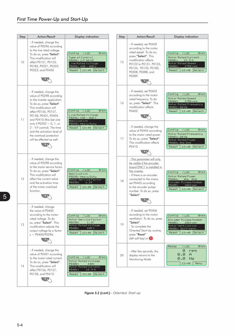
First Time Power-Up and Start-Up
5-4
5
- Oriented Start-up
Step Action/Result Display indication
10
- If needed, change thevalue of P0296 accordingto the line rated voltage.To do so, press "Select".This modification willaffect P0151, P0153,P0185, P0321, P0322,P0323, and P0400.
Config LOC 0rpm
Reset 13:48 Select
Type of ControlP0202: V/F 60 HZ
Line Rated VoltageP0296: 440 - 460 V
11
- If needed, change the value of P0298 according to the inverter application. To do so, press "Select".This modification will affect P0156, P0157, P0158, P0401, P0404 and P0410 (this last one only if P0202 = 0, 1, or 2 – V/f control). The time and the activation level of the overload protection will be affected as well.
Config LOC 0rpm
Reset 13:48 Select
Line Rated VoltageP0296: 440 - 460 V
ApplicationP0298: Heavy Duty
12
- If needed, change the value of P0398 according to the motor service factor. To do so, press “Select”.This modification will affect the current value and the activation time of the motor overload function.
Config LOC 0rpm
Reset 13:48 Select
ApplicationP0298: Heavy DutyMotor Service FactorP0398: 1.15
13
- If needed, change the value of P0400 according to the motor rated voltage. To do so, press “Select”. This modification adjusts the output voltage by a factor x = P0400/P0296.
Config LOC 0rpm
Reset 13:48 Select
Motor Service FactorP0398: 1.15Motor Rated VoltageP0400: 440 V
14
- If needed, change the value of P0401 according to the motor rated current. To do so, press “Select”.This modification will affect P0156, P0157, P0158, and P0410.
Config LOC 0rpm
Reset 13:48 Select
Motor Rated VoltageP0400: 440VMotor Rated CurrentP0401: 13.5 A
Step Action/Result Display indication
15
- If needed, set P0402 according to the motor rated speed. To do so, press “Select”. This modification affects P0122 to P0131, P0133, P0134, P0135, P0182, P0208, P0288, and P0289.
Config LOC 0rpm
Reset 13:48 Select
Motor Rated CurrentP0401: 13.5 A
Motor Rated SpeedP0402: 1750 rpm
16
- If needed, set P0403according to the motorrated frequency. To doso, press “Select”. Thismodification affectsP0402.
Config LOC 0rpm
Reset 13:48 Select
Motor Rated SpeedP0402: 1750 rpm
Motor Rated FrequencyP0403: 60 Hz
17
- If needed, change thevalue of P0404 according to the motor rated power.To do so, press “Select”.This modification affectsP0410.
Config LOC 0rpm
Reset 13:48 Select
Motor Rated FrequencyP0403: 60 Hz
Motor Rated PowerP0404: 4hp 3kW
18
- This parameter will only be visible if the encoder board ENC1 is installed in the inverter.- If there is an encoder connected to the motor, set P0405 according to the encoder pulses number. To do so, press “Select”.
Config LOC 0rpm
Reset 13:48 Select
Motor Rated PowerP0404: 4hp 3kW
Encoder Pulses NumberP0405: 1024 ppr
19
- If needed, set P0406 according to the motor ventilation. To do so, press “Select”.- To complete the Oriented Start-Up routine, press “Reset”(left soft key) or .
Config LOC 0rpm
Reset 13:48 Select
Encoder Pulses Number P0405: 1024 ppr
Motor VentilationP0406: Self-Vent.
20- After few seconds, the display returns to the Monitoring Mode.
Ready LOC 0rpm
13:48 Menu
0 rpm0.0 A0.0 Hz
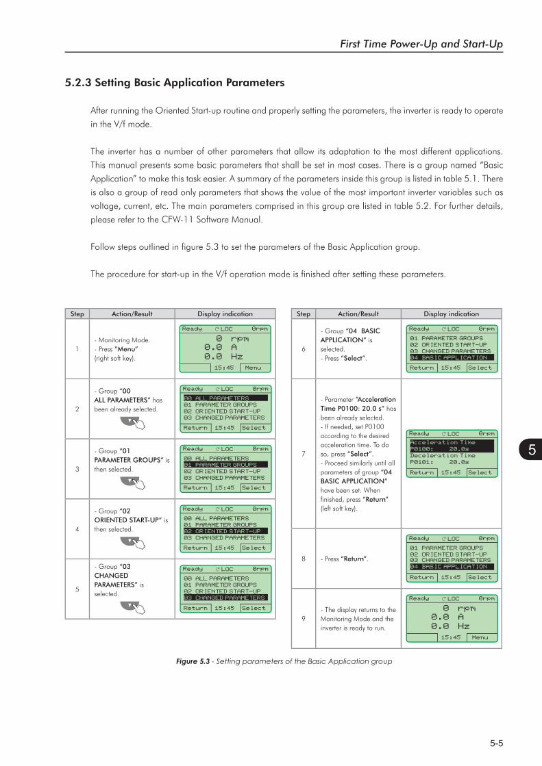
First Time Power-Up and Start-Up
5-5
5
Step Action/Result Display indication
1- Monitoring Mode.- Press “Menu”(right soft key).
Ready LOC 0rpm
15:45 Menu
0 rpm0.0 A0.0 Hz
2
- Group “00ALL PARAMETERS” has been already selected.
Ready LOC 0rpm
Return 15:45 Select
00 ALL PARAMETERS01 PARAMETER GROUPS02 ORIENTED START-UP03 CHANGED PARAMETERS
3
- Group “01PARAMETER GROUPS” is then selected.
Ready LOC 0rpm
Return 15:45 Select
00 ALL PARAMETERS01 PARAMETER GROUPS02 ORIENTED START-UP03 CHANGED PARAMETERS
4
- Group “02ORIENTED START-UP” is then selected.
Ready LOC 0rpm
Return 15:45 Select
00 ALL PARAMETERS01 PARAMETER GROUPS02 ORIENTED START-UP03 CHANGED PARAMETERS
5
- Group “03 CHANGEDPARAMETERS” isselected.
Ready LOC 0rpm
Return 15:45 Select
00 ALL PARAMETERS01 PARAMETER GROUPS02 ORIENTED START-UP03 CHANGED PARAMETERS
5.2.3 Setting Basic Application Parameters
After running the Oriented Start-up routine and properly setting the parameters, the inverter is ready to operate
in the V/f mode.
The inverter has a number of other parameters that allow its adaptation to the most different applications.
This manual presents some basic parameters that shall be set in most cases. There is a group named “Basic
Application” to make this task easier. A summary of the parameters inside this group is listed in table 5.1. There
is also a group of read only parameters that shows the value of the most important inverter variables such as
voltage, current, etc. The main parameters comprised in this group are listed in table 5.2. For further details,
please refer to the CFW-11 Software Manual.
Follow steps outlined in figure 5.3 to set the parameters of the Basic Application group.
The procedure for start-up in the V/f operation mode is finished after setting these parameters.
Figure 5.3 - Setting parameters of the Basic Application group
Step Action/Result Display indication
6
- Group “04 BASIC APPLICATION” is selected.- Press “Select”.
Ready LOC 0rpm
Return 15:45 Select
01 PARAMETER GROUPS02 ORIENTED START-UP03 CHANGED PARAMETERS04 BASIC APPLICATION
7
- Parameter “Acceleration Time P0100: 20.0 s” has been already selected.- If needed, set P0100 according to the desired acceleration time. To do so, press “Select”.- Proceed similarly until all parameters of group “04BASIC APPLICATION”have been set. When finished, press “Return”(left soft key).
Ready LOC 0rpm
Return 15:45 Select
Acceleration TimeP0100: 20.0sDeceleration TimeP0101: 20.0s
8 - Press “Return”.
Ready LOC 0rpm
Return 15:45 Select
01 PARAMETER GROUPS02 ORIENTED START-UP03 CHANGED PARAMETERS04 BASIC APPLICATION
9- The display returns to the Monitoring Mode and the inverter is ready to run.
Ready LOC 0rpm
15:45 Menu
0 rpm0.0 A0.0 Hz
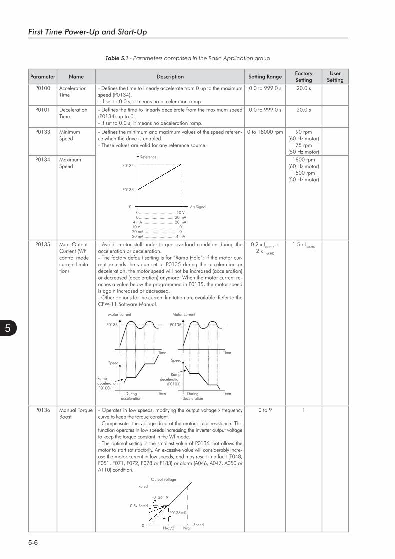
First Time Power-Up and Start-Up
5-6
5
Parameter Name Description Setting RangeFactorySetting
UserSetting
P0100 AccelerationTime
- Defines the time to linearly accelerate from 0 up to the maximum speed (P0134).- If set to 0.0 s, it means no acceleration ramp.
0.0 to 999.0 s 20.0 s
P0101 DecelerationTime
- Defines the time to linearly decelerate from the maximum speed (P0134) up to 0.- If set to 0.0 s, it means no deceleration ramp.
0.0 to 999.0 s 20.0 s
P0133 MinimumSpeed
- Defines the minimum and maximum values of the speed referen-ce when the drive is enabled.- These values are valid for any reference source.
Reference
P0134
P0133
0 Alx Signal0................................ 10 V0...............................20 mA
4 mA ............................20 mA10 V..................................020 mA...............................020 mA............................4 mA
0 to 18000 rpm 90 rpm (60 Hz motor)
75 rpm(50 Hz motor)
P0134 MaximumSpeed
1800 rpm (60 Hz motor)
1500 rpm (50 Hz motor)
P0135 Max. Output Current (V/F control mode current limita-tion)
- Avoids motor stall under torque overload condition during the acceleration or deceleration.- The factory default setting is for “Ramp Hold”: if the motor cur-rent exceeds the value set at P0135 during the acceleration or deceleration, the motor speed will not be increased (acceleration) or decreased (deceleration) anymore. When the motor current re-aches a value below the programmed in P0135, the motor speed is again increased or decreased.- Other options for the current limitation are available. Refer to the CFW-11 Software Manual.
Speed
Motor current Motor current
P0135
Ramp acceleration(P0100)
Duringacceleration
P0135
Ramp deceleration
(P0101)
Speed
Duringdeceleration
TimeTime
TimeTime
0.2 x Irat-HD to 2 x Irat-HD
1.5 x Irat-HD
P0136 Manual Torque Boost
- Operates in low speeds, modifying the output voltage x frequency curve to keep the torque constant.- Compensates the voltage drop at the motor stator resistance. This function operates in low speeds increasing the inverter output voltage to keep the torque constant in the V/f mode.- The optimal setting is the smallest value of P0136 that allows the motor to start satisfactorily. An excessive value will considerably incre-ase the motor current in low speeds, and may result in a fault (F048, F051, F071, F072, F078 or F183) or alarm (A046, A047, A050 or A110) condition.
Output voltage
Rated
P0136=9
P0136=0
0.5x Rated
0Nrat/2 Nrat
Speed
0 to 9 1
Table 5.1 - Parameters comprised in the Basic Application group
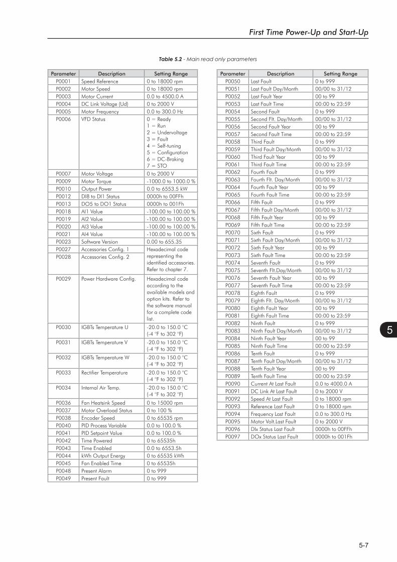
First Time Power-Up and Start-Up
5-7
5
Table 5.2 - Main read only parameters
Parameter Description Setting RangeP0001 Speed Reference 0 to 18000 rpmP0002 Motor Speed 0 to 18000 rpmP0003 Motor Current 0.0 to 4500.0 AP0004 DC Link Voltage (Ud) 0 to 2000 VP0005 Motor Frequency 0.0 to 300.0 HzP0006 VFD Status 0 = Ready
1 = Run2 = Undervoltage3 = Fault4 = Self-tuning5 = Configuration6 = DC-Braking7 = STO
P0007 Motor Voltage 0 to 2000 VP0009 Motor Torque -1000.0 to 1000.0 %P0010 Output Power 0.0 to 6553.5 kWP0012 DI8 to DI1 Status 0000h to 00FFh P0013 DO5 to DO1 Status 0000h to 001Fh P0018 AI1 Value -100.00 to 100.00 %P0019 AI2 Value -100.00 to 100.00 %P0020 AI3 Value -100.00 to 100.00 %P0021 AI4 Value -100.00 to 100.00 %P0023 Software Version 0.00 to 655.35 P0027 Accessories Config. 1 Hexadecimal code
representing the identified accessories. Refer to chapter 7.
P0028 Accessories Config. 2
P0029 Power Hardware Config. Hexadecimal code according to the available models and option kits. Refer to the software manual for a complete code list.
P0030 IGBTs Temperature U -20.0 to 150.0 °C (-4 °F to 302 °F)
P0031 IGBTs Temperature V -20.0 to 150.0 °C(-4 °F to 302 °F)
P0032 IGBTs Temperature W -20.0 to 150.0 °C(-4 °F to 302 °F)
P0033 Rectifier Temperature -20.0 to 150.0 °C(-4 °F to 302 °F)
P0034 Internal Air Temp. -20.0 to 150.0 °C(-4 °F to 302 °F)
P0036 Fan Heatsink Speed 0 to 15000 rpmP0037 Motor Overload Status 0 to 100 %P0038 Encoder Speed 0 to 65535 rpmP0040 PID Process Variable 0.0 to 100.0 %P0041 PID Setpoint Value 0.0 to 100.0 %P0042 Time Powered 0 to 65535hP0043 Time Enabled 0.0 to 6553.5hP0044 kWh Output Energy 0 to 65535 kWhP0045 Fan Enabled Time 0 to 65535hP0048 Present Alarm 0 to 999 P0049 Present Fault 0 to 999
Parameter Description Setting RangeP0050 Last Fault 0 to 999P0051 Last Fault Day/Month 00/00 to 31/12P0052 Last Fault Year 00 to 99P0053 Last Fault Time 00:00 to 23:59P0054 Second Fault 0 to 999P0055 Second Flt. Day/Month 00/00 to 31/12P0056 Second Fault Year 00 to 99P0057 Second Fault Time 00:00 to 23:59P0058 Third Fault 0 to 999P0059 Third Fault Day/Month 00/00 to 31/12P0060 Third Fault Year 00 to 99P0061 Third Fault Time 00:00 to 23:59P0062 Fourth Fault 0 to 999P0063 Fourth Flt. Day/Month 00/00 to 31/12P0064 Fourth Fault Year 00 to 99P0065 Fourth Fault Time 00:00 to 23:59P0066 Fifth Fault 0 to 999P0067 Fifth Fault Day/Month 00/00 to 31/12P0068 Fifth Fault Year 00 to 99P0069 Fifth Fault Time 00:00 to 23:59P0070 Sixth Fault 0 to 999P0071 Sixth Fault Day/Month 00/00 to 31/12P0072 Sixth Fault Year 00 to 99P0073 Sixth Fault Time 00:00 to 23:59P0074 Seventh Fault 0 to 999P0075 Seventh Flt.Day/Month 00/00 to 31/12P0076 Seventh Fault Year 00 to 99P0077 Seventh Fault Time 00:00 to 23:59P0078 Eighth Fault 0 to 999P0079 Eighth Flt. Day/Month 00/00 to 31/12P0080 Eighth Fault Year 00 to 99P0081 Eighth Fault Time 00:00 to 23:59P0082 Ninth Fault 0 to 999P0083 Ninth Fault Day/Month 00/00 to 31/12P0084 Ninth Fault Year 00 to 99P0085 Ninth Fault Time 00:00 to 23:59P0086 Tenth Fault 0 to 999P0087 Tenth Fault Day/Month 00/00 to 31/12P0088 Tenth Fault Year 00 to 99P0089 Tenth Fault Time 00:00 to 23:59P0090 Current At Last Fault 0.0 to 4000.0 AP0091 DC Link At Last Fault 0 to 2000 VP0092 Speed At Last Fault 0 to 18000 rpmP0093 Reference Last Fault 0 to 18000 rpmP0094 Frequency Last Fault 0.0 to 300.0 HzP0095 Motor Volt.Last Fault 0 to 2000 VP0096 DIx Status Last Fault 0000h to 00FFhP0097 DOx Status Last Fault 0000h to 001Fh

First Time Power-Up and Start-Up
5-8
5
Step Action/Result Display indication
1Monitoring Mode.- Press “Menu” (right soft key).
Ready LOC 0rpm
16:10 Menu
0 rpm0.0 A0.0 Hz
2
- Group “00ALL PARAMETERS” is already selected.
Ready LOC 0rpm
Return 16:10 Select
00 ALL PARAMETERS01 PARAMETER GROUPS02 ORIENTED START-UP03 CHANGED PARAMETERS
3
- Group “01PARAMETER GROUPS" is selected.- Press “Select”
Ready LOC 0rpm
Return 16:10 Select
00 ALL PARAMETERS01 PARAMETER GROUPS02 ORIENTED START-UP03 CHANGED PARAMETERS
4
- A new list of groups is displayed and group “20 Ramps” is selected.
- Press until you reach group "30 HMI".
Ready LOC 0rpm
Return 16:10 Select
20 Ramps21 Speed References22 Speed Limits23 V/F Control
5- Group “30 HMI” is selected.- Press “Select”.
Ready LOC 0rpm
Return 16:10 Select
27 V/F DC Volt. Limit.28 Dynamic Braking29 Vector Control30 HMI
5.3 SETTING DATE AND TIME
Step Action/Result Display indication
6
- Parameter “Day P0194”is already selected.- If needed, set P0194 according to the actual day. To do so, press “Select” and then,
or to change P0194 value.- Follow the same steps to set parameters "MonthP0195” to “SecondsP0199”.
Ready LOC 0rpm
Return 16:10 Select
DayP0194: 06
MonthP0195: 10
7
- Once the setting of P0199 is over, the Real Time Clock is now updated.- Press “Return” (left soft key).
Ready LOC 0rpm
Return 18:11 Select
MinutesP0198: 11
SecondsP0199: 34
8- Press “Return”.
Ready LOC 0rpm
Return 18:11 Select
27 V/F DC Volt. Limit.28 Dynamic Braking29 Vector Control30 HMI
9- Press “Return”.
Ready LOC 0rpm
Return 18:11 Select
00 ALL PARAMETERS01 PARAMETER GROUPS02 ORIENTED START-UP03 CHANGED PARAMETERS
10- The display is back to the Monitoring Mode.
Ready LOC 0rpm
18:11 Menu
0 rpm0.0 A0.0 Hz
Figure 5.4 - Setting date and time
5.4 BLOCKING PARAMETERS MODIFICATION
To prevent unauthorized or unintended parameters modification, parameter P0000 should be set to a value
different from 5. Follow the same procedures described in item 5.2.1.
First Time Power-Up and Start-Up
5-9
5
5.5 HOW TO CONNECT A PC
NOTES!- Always use a standard host/device shielded USB cable. Unshielded cables may lead to communication
errors.
- Recommended cables: Samtec:
USBC-AM-MB-B-B-S-1 (1 meter);
USBC-AM-MB-B-B-S-2 (2 meters);
USBC-AM-MB-B-B-S-3 (3 meters).
- The USB connection is galvanically isolated from the mains power supply and from other high
voltages internal to the inverter. However, the USB connection is not isolated from the Protective
Ground (PE). Use an isolated notebook for the USB connection or a desktop connected to the same
Protective Ground (PE) of the inverter.
Install the SuperDrive G2 software to control motor speed, view, or edit inverter parameters through a personal
computer (PC).
Basic procedures for transferring data from the PC to the inverter:
1. Install the SuperDrive G2 software in the PC;
2. Connect the PC to the inverter through a USB cable;
3. Start SuperDrive G2;
4. Choose “Open” and the files stored in the PC will be displayed;
5. Select the file;
6. Use the command “Write Parameters to the Drive”.
All parameters are now transferred to the inverter.
For further information on SuperDrive G2 software, please refer SuperDrive Manual.
5.6 FLASH MEMORY MODULE
Location as presented in figure 2.2 item D.
Features:
- Store a copy of the inverter parameters;
- Transfer parameters stored in the FLASH memory to the inverter;
- Transfer firmware stored in the FLASH memory to the inverter;
- Store programs created by the SoftPLC.
Whenever the inverter is powered up, this program is transferred to the RAM memory located in the inverter
control board and executed.
Refer to the CFW-11 Software Manual and to SoftPLC Manual for further details.
ATTENTION! Before installing or removing the FLASH memory module, disconnect the inverter power supply and
wait for the complete discharge of the capacitors.
Troubleshooting and Maintenance
6-1
6
TROUBLESHOOTING AND MAINTENANCE
This chapter:
- Lists all faults and alarms that may occur.
- Indicates the possible causes of each fault and alarm.
- Lists most frequent problems and corrective actions.
- Presents instructions for periodic inspections and preventive
maintenance in the equipment.
6.1 OPERATION OF THE FAULTS AND ALARMS
When a fault is detected (fault (FXXX)):
The PWM pulses are blocked;
The keypad displays the fault code and description;
The “STATUS” LED starts flashing red;
The output relay set to "NO FAULT" opens;
Some control circuitry data is saved in the EEPROM memory:
- Keypad and EP (Electronic Pot) speed references, in case the function “Reference backup” is enabled in
P0120;
- The fault code that occurred (shifts the last nine previous faults and alarms);
- The state of the motor overload function integrator;
- The state of the operating hours counter (P0043) and the powered-up hours counter (P0042).
Reset the inverter to return the drive to a “READY” condition in the event of a fault. The following reset options
are available:
Removing the power supply and reapplying it (power-on reset);
Pressing the operator key (manual reset);
Through the "Reset" soft key;
Automatically by setting P0206 (auto-reset);
Through a digital input: DIx=20 (P0263 to P0270).
When an alarm situation (alarm (AXXX)) is detected:
The keypad displays the alarm code and description;
The “STATUS” LED changes to yellow;
The PWM pulses are not blocked (the inverter is still operating).
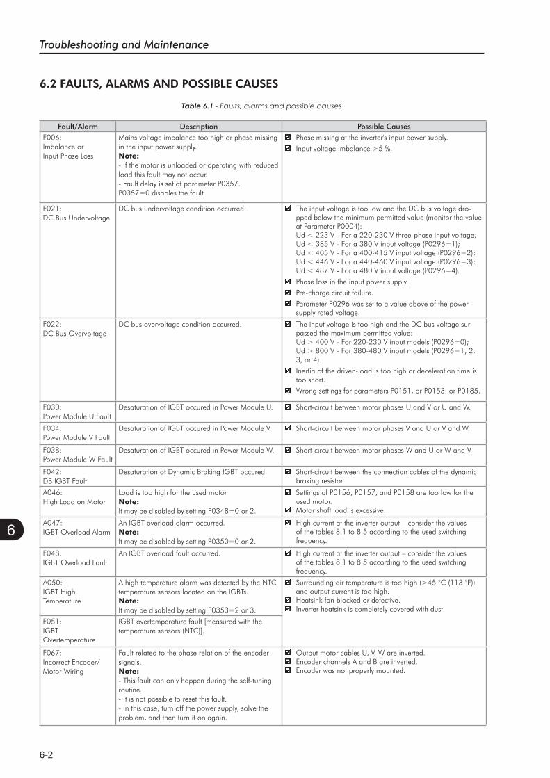
Troubleshooting and Maintenance
6-2
6
Fault/Alarm Description Possible CausesF006:Imbalance orInput Phase Loss
Mains voltage imbalance too high or phase missing in the input power supply.Note:- If the motor is unloaded or operating with reduced load this fault may not occur.- Fault delay is set at parameter P0357. P0357=0 disables the fault.
Phase missing at the inverter's input power supply.
Input voltage imbalance >5 %.
F021:DC Bus Undervoltage
DC bus undervoltage condition occurred. The input voltage is too low and the DC bus voltage dro-pped below the minimum permitted value (monitor the value at Parameter P0004):Ud < 223 V - For a 220-230 V three-phase input voltage;Ud < 385 V - For a 380 V input voltage (P0296=1);Ud < 405 V - For a 400-415 V input voltage (P0296=2);Ud < 446 V - For a 440-460 V input voltage (P0296=3);Ud < 487 V - For a 480 V input voltage (P0296=4).
Phase loss in the input power supply.
Pre-charge circuit failure.
Parameter P0296 was set to a value above of the power supply rated voltage.
F022:DC Bus Overvoltage
DC bus overvoltage condition occurred. The input voltage is too high and the DC bus voltage sur-passed the maximum permitted value:Ud > 400 V - For 220-230 V input models (P0296=0);Ud > 800 V - For 380-480 V input models (P0296=1, 2, 3, or 4).
Inertia of the driven-load is too high or deceleration time is too short.
Wrong settings for parameters P0151, or P0153, or P0185.
F030:Power Module U Fault
Desaturation of IGBT occured in Power Module U. Short-circuit between motor phases U and V or U and W.
F034:Power Module V Fault
Desaturation of IGBT occured in Power Module V. Short-circuit between motor phases V and U or V and W.
F038:Power Module W Fault
Desaturation of IGBT occured in Power Module W. Short-circuit between motor phases W and U or W and V.
F042:DB IGBT Fault
Desaturation of Dynamic Braking IGBT occured. Short-circuit between the connection cables of the dynamic braking resistor.
A046:High Load on Motor
Load is too high for the used motor.Note:It may be disabled by setting P0348=0 or 2.
Settings of P0156, P0157, and P0158 are too low for the used motor.Motor shaft load is excessive.
A047:IGBT Overload Alarm
An IGBT overload alarm occurred.Note:It may be disabled by setting P0350=0 or 2.
High current at the inverter output – consider the values of the tables 8.1 to 8.5 according to the used switching frequency.
F048:IGBT Overload Fault
An IGBT overload fault occurred. High current at the inverter output – consider the values of the tables 8.1 to 8.5 according to the used switching frequency.
A050:IGBT High Temperature
A high temperature alarm was detected by the NTC temperature sensors located on the IGBTs.Note:It may be disabled by setting P0353=2 or 3.
Surrounding air temperature is too high (>45 °C (113 °F)) and output current is too high.Heatsink fan blocked or defective.Inverter heatsink is completely covered with dust.
F051:IGBTOvertemperature
IGBT overtemperature fault [measured with the temperature sensors (NTC)].
F067:Incorrect Encoder/Motor Wiring
Fault related to the phase relation of the encoder signals.Note:- This fault can only happen during the self-tuning routine.- It is not possible to reset this fault.- In this case, turn off the power supply, solve the problem, and then turn it on again.
Output motor cables U, V, W are inverted.Encoder channels A and B are inverted.Encoder was not properly mounted.
6.2 FAULTS, ALARMS AND POSSIBLE CAUSES
Table 6.1 - Faults, alarms and possible causes
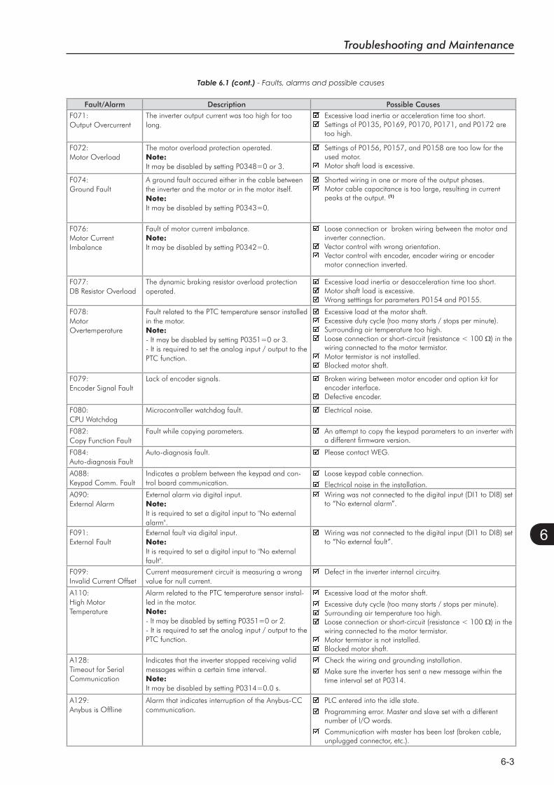
Troubleshooting and Maintenance
6-3
6
Fault/Alarm Description Possible CausesF071:Output Overcurrent
The inverter output current was too high for too long.
Excessive load inertia or acceleration time too short.Settings of P0135, P0169, P0170, P0171, and P0172 are too high.
F072:Motor Overload
The motor overload protection operated.Note:It may be disabled by setting P0348=0 or 3.
Settings of P0156, P0157, and P0158 are too low for the used motor.Motor shaft load is excessive.
F074:Ground Fault
A ground fault occured either in the cable between the inverter and the motor or in the motor itself.Note:It may be disabled by setting P0343=0.
Shorted wiring in one or more of the output phases.Motor cable capacitance is too large, resulting in current peaks at the output. (1)
F076:Motor Current Imbalance
Fault of motor current imbalance.Note:It may be disabled by setting P0342=0.
Loose connection or broken wiring between the motor and inverter connection.Vector control with wrong orientation.Vector control with encoder, encoder wiring or encoder motor connection inverted.
F077:DB Resistor Overload
The dynamic braking resistor overload protection operated.
Excessive load inertia or desacceleration time too short.Motor shaft load is excessive.Wrong setttings for parameters P0154 and P0155.
F078:MotorOvertemperature
Fault related to the PTC temperature sensor installed in the motor.Note:- It may be disabled by setting P0351=0 or 3.- It is required to set the analog input / output to the PTC function.
Excessive load at the motor shaft.Excessive duty cycle (too many starts / stops per minute).Surrounding air temperature too high.Loose connection or short-circuit (resistance < 100 ) in the wiring connected to the motor termistor.Motor termistor is not installed.Blocked motor shaft.
F079:Encoder Signal Fault
Lack of encoder signals. Broken wiring between motor encoder and option kit for encoder interface.Defective encoder.
F080:CPU Watchdog
Microcontroller watchdog fault. Electrical noise.
F082:Copy Function Fault
Fault while copying parameters. An attempt to copy the keypad parameters to an inverter with a different firmware version.
F084:Auto-diagnosis Fault
Auto-diagnosis fault. Please contact WEG.
A088:Keypad Comm. Fault
Indicates a problem between the keypad and con-trol board communication.
Loose keypad cable connection.
Electrical noise in the installation.A090:External Alarm
External alarm via digital input.Note:It is required to set a digital input to "No external alarm".
Wiring was not connected to the digital input (DI1 to DI8) set to “No external alarm”.
F091:External Fault
External fault via digital input.Note:It is required to set a digital input to "No external fault".
Wiring was not connected to the digital input (DI1 to DI8) set to “No external fault”.
F099:Invalid Current Offset
Current measurement circuit is measuring a wrong value for null current.
Defect in the inverter internal circuitry.
A110:High Motor Temperature
Alarm related to the PTC temperature sensor instal-led in the motor.Note:- It may be disabled by setting P0351=0 or 2. - It is required to set the analog input / output to the PTC function.
Excessive load at the motor shaft.
Excessive duty cycle (too many starts / stops per minute).Surrounding air temperature too high.Loose connection or short-circuit (resistance < 100 ) in the wiring connected to the motor termistor.Motor termistor is not installed.Blocked motor shaft.
A128:Timeout for Serial Communication
Indicates that the inverter stopped receiving valid messages within a certain time interval.Note:It may be disabled by setting P0314=0.0 s.
Check the wiring and grounding installation.
Make sure the inverter has sent a new message within the time interval set at P0314.
A129:Anybus is Offline
Alarm that indicates interruption of the Anybus-CC communication.
PLC entered into the idle state.
Programming error. Master and slave set with a different number of I/O words.
Communication with master has been lost (broken cable, unplugged connector, etc.).
- Faults, alarms and possible causes
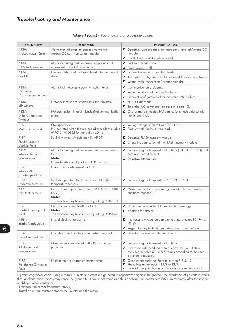
Troubleshooting and Maintenance
6-4
6
Fault/Alarm Description Possible CausesA130:Anybus Access Error
Alarm that indicates an access error to the Anybus-CC communication module.
Defective, unrecognized, or improperly installed Anybus-CC module.
Conflict with a WEG option board.
A133:CAN Not Powered
Alarm indicating that the power supply was not connected to the CAN controller.
Broken or loose cable.
Power supply is off.A134:Bus Off
Inverter CAN interface has entered into the bus-off state.
Incorrect communication baud-rate.
Two nodes configured with the same address in the network.
Wrong cable connection (inverted signals).
A135:CANopenCommunication Error
Alarm that indicates a communication error. Communication problems.
Wrong master configuration/settings.
Incorrect configuration of the communication objects.
A136:Idle Master
Network master has entered into the idle state. PLC in IDLE mode.
Bit of the PLC command register set to zero (0).
A137:DNet Connection Timeout
I/O connection timeout - DeviceNet communication alarm.
One or more allocated I/O connections have entered into the timeout state.
F150:Motor Overspeed
Overspeed fault.It is activated when the real speed exceeds the value of P0134+P0132 for more than 20 ms.
Wrong settings of P0161 and/or P0162.Problem with the hoist-type load.
F151:FLASH Memory Module Fault
FLASH Memory Module fault (MMF-01). Defective FLASH memory module.
Check the connection of the FLASH memory module.
A152:Internal Air High Temperature
Alarm indicating that the internal air temperature is too high.Note:It may be disabled by setting P0353=1 or 3.
Surrounding air temperature too high (>45 °C (113 °F)) and excessive output current.
Defective internal fan.
F153:Internal Air Overtemperature
Internal air overtemperature fault.
F156:Undertemperature
Undertemperature fault, measured at the IGBT temperature sensors.
A177:Fan Replacement
Heatsink fan replacement alarm (P0045 > 50000 hours).Note:This function may be disabled by setting P0354=0.
Maximum number of operating hours for the heatsink fan has been reached.
F179:Heatsink Fan Speed Fault
Heatsink fan speed feedback fault.Note:This function may be disabled by setting P0354=0.
Dirt at the heatsink fan blades and ball bearings.
Heatsink fan defect.
A181:Invalid Clock Value
Invalid clock value alarm. It is necessary to set date and time at parameters P0194 to P0199.
Keypad battery is discharged, defective, or not installed.
F182:Pulse Feedback Fault
Indicates a fault on the output pulses feedback. Defect in the inverter internal circuitry.
F183:IGBT overload + Temperature
Overtemperature related to the IGBTs overload protection.
Surrounding air temperature too high.
Operation with overload at frequencies below 10 Hz – consider the table 8.1 to 8.5 values according to the used switching frequency.
F185Pre-charge Contactor Fault
Fault in the pre-charge contactor circuit. Open command fuse. Refer to section 3.2.3.1.2.Phase loss at the input in L1/R or L2/S.Defect in the pre-charge contactor and/or related circuit.
- Faults, alarms and possible causes
(1) Very long motor cables (longer than 100 meters) present a high parasite capacitance against the ground. The circulation of parasite currents through those capacitances may cause the ground fault circuit activation and thus disabling the inverter with F074, immediately after the inverter enabling. Possible solutions:- Decrease the carrier frequency (P0297).- Install an output reactor between the inverter and the motor.
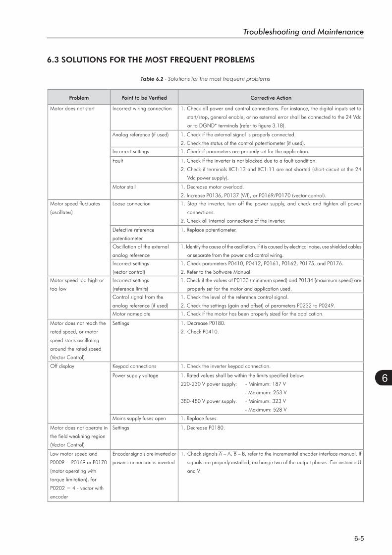
Troubleshooting and Maintenance
6-5
6
6.3 SOLUTIONS FOR THE MOST FREQUENT PROBLEMS
Table 6.2 - Solutions for the most frequent problems
Problem Point to be Verified Corrective Action
Motor does not start Incorrect wiring connection 1. Check all power and control connections. For instance, the digital inputs set to
start/stop, general enable, or no external error shall be connected to the 24 Vdc
or to DGND* terminals (refer to figure 3.18).
Analog reference (if used) 1. Check if the external signal is properly connected.
2. Check the status of the control potentiometer (if used).
Incorrect settings 1. Check if parameters are properly set for the application.
Fault 1. Check if the inverter is not blocked due to a fault condition.
2. Check if terminals XC1:13 and XC1:11 are not shorted (short-circuit at the 24
Vdc power supply).
Motor stall 1. Decrease motor overload.
2. Increase P0136, P0137 (V/f), or P0169/P0170 (vector control).
Motor speed fluctuates
(oscillates)
Loose connection 1. Stop the inverter, turn off the power supply, and check and tighten all power
connections.
2. Check all internal connections of the inverter.
Defective reference
potentiometer
1. Replace potentiometer.
Oscillation of the external
analog reference
1. Identify the cause of the oscillation. If it is caused by electrical noise, use shielded cables
or separate from the power and control wiring.
Incorrect settings
(vector control)
1. Check parameters P0410, P0412, P0161, P0162, P0175, and P0176.
2. Refer to the Software Manual.
Motor speed too high or
too low
Incorrect settings
(reference limits)
1. Check if the values of P0133 (minimum speed) and P0134 (maximum speed) are
properly set for the motor and application used.
Control signal from the
analog reference (if used)
1. Check the level of the reference control signal.
2. Check the settings (gain and offset) of parameters P0232 to P0249.
Motor nameplate 1. Check if the motor has been properly sized for the application.
Motor does not reach the
rated speed, or motor
speed starts oscillating
around the rated speed
(Vector Control)
Settings 1. Decrease P0180.
2. Check P0410.
Off display Keypad connections 1. Check the inverter keypad connection.
Power supply voltage 1. Rated values shall be within the limits specified below:
220-230 V power supply: - Minimum: 187 V
- Maximum: 253 V
380-480 V power supply: - Minimum: 323 V
- Maximum: 528 V
Mains supply fuses open 1. Replace fuses.
Motor does not operate in
the field weakning region
(Vector Control)
Settings 1. Decrease P0180.
Low motor speed and
P0009 = P0169 or P0170
(motor operating with
torque limitation), for
P0202 = 4 - vector with
encoder
Encoder signals are inverted or
power connection is inverted
1. Check signals A – A, B – B, refer to the incremental encoder interface manual. If
signals are properly installed, exchange two of the output phases. For instance U
and V.
Troubleshooting and Maintenance
6-6
6
6.4 INFORMATION FOR CONTACTING TECHNICAL SUPPORT
NOTE! For technical support and servicing, it is important to have the following information in hand:
Inverter model;
Serial number, manufacturing date, and hardware revision that are listed in the product nameplate
(refer to item 2.4);
Installed software version (check parameter P0023);
Application data and inverter settings.
6.5 PREVENTIVE MAINTENANCE
DANGER! Always turn off the mains power supply before touching any electrical component associated to
the inverter.
High voltage may still be present even after disconnecting the power supply.
To prevent electric shock, wait at least 10 minutes after turning off the input power for the complete
discharge of the power capacitors.
Always connect the equipment frame to the protective ground (PE). Use the adequate connection
terminal in the inverter.
ATTENTION! The electronic boards have electrostatic discharge sensitive components.
Do not touch the components or connectors directly. If needed, first touch the grounded mettalic
frame or wear a ground strap.
Do not perform any withstand voltage test! If needed, consult WEG.
The inverters require low maintenance when properly installed and operated. Table 6.3 presents main procedures
and time intervals for preventive maintenance. Table 6.4 provides recommended periodic inspections to be
performed every 6 months after inverter start-up.
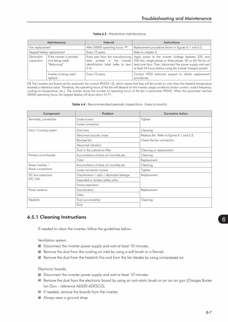
Troubleshooting and Maintenance
6-7
6
Table 6.3 - Preventive maintenance
Maintenance Interval Instructions
Fan replacement After 50000 operating hours. (1) Replacement procedure shown in figures 6.1 and 6.2.
Keypad battery replacement Every 10 years. Refer to chapter 4.
Electrolyticcapacitors
If the inverter is stocked (not being used): “Reforming”
Every year from the manufacturing date printed in the inverter identification label (refer to item 2.4).
Apply power to the inverter (voltage between 220 and 230 Vac, single-phase or three-phase, 50 or 60 Hz) for at least one hour. Then, disconnect the power supply and wait at least 24 hours before using the inverter (reapply power).
Inverter is being used:replace
Every 10 years. Contact WEG technical support to obtain replacement procedures.
(1) The inverters are factory set for automatic fan control (P0352=2), which means that they will be turned on only when the heatsink temperature exceeds a reference value. Therefore, the operating hours of the fan will depend on the inverter usage conditions (motor current, output frequency, cooling air temperature, etc.). The inverter stores the number of operating hours of the fan in parameter P0045. When this parameter reaches 50000 operating hours, the keypad display will show alarm A177.
Component Problem Corrective Action
Terminals, connectors Loose screws Tighten
Loose connectors
Fans / Cooling system Dirty fans Cleaning
Abnormal acoustic noise Replace fan. Refer to figures 6.1 and 6.2.
Blocked fan Check the fan connection.
Abnormal vibration
Dust in the cabinet air filter Cleaning or replacement.
Printed circuit boards Accumulation of dust, oil, humidity, etc. Cleaning
Odor Replacement
Power module / Accumulation of dust, oil, humidity, etc. CleaningPower connections Loose connection screws Tighten
DC bus capacitors Discoloration / odor / electrolyte leakage Replacement (DC link) Expanded or broken safety valve
Frame expansion
Power resistors Discoloration Replacement
Odor
Heatsink Dust accumulation Cleaning
Dirty
Table 6.4
6.5.1 Cleaning Instructions
If needed to clean the inverter, follow the guidelines below:
Ventilation system:
Disconnect the inverter power supply and wait at least 10 minutes.
Remove the dust from the cooling air inlet by using a soft brush or a flannel.
Remove the dust from the heatsink fins and from the fan blades by using compressed air.
Electronic boards:
Disconnect the inverter power supply and wait at least 10 minutes.
Remove the dust from the electronic board by using an anti-static brush or an ion air gun (Charges Burtes
Ion Gun - reference A6030-6DESCO).
If needed, remove the boards from the inverter.
Always wear a ground strap.
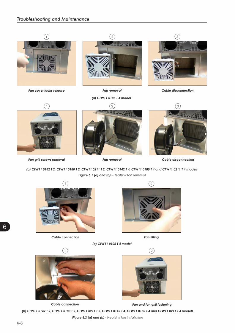
Troubleshooting and Maintenance
6-8
6
Figure 6.1 (a) and (b) - Heatsink fan removal
3
3
2
2
1
1
Figure 6.2 (a) and (b) - Heatsink fan installation
21
1 2

Option Kits and Accessories
7-1
7
OPTION KITS AND ACCESSORIES
This chapter presents:The option kits that can be incorporated to the inverter from
the factory:
- Braking IGBT;
- Safety Stop according to EN 954-1 category 3;
- External 24 Vdc power supply for control and keypad.
Instructions for the proper use of the option kits.
The accessories that can be incorporated to the inverters.
Details for the installation, operation, and programming of the accessories are described in their own manuals
and were not included in this chapter.
7.1 OPTION KITS
Some models cannot incorporate all available option kits. Refer to table 8.1 for a detailed description of the
option kits that are available for each inverter model.
The inverter codification is described in chapter 2.
7.1.1 Braking IGBT
Inverters with the following codification: CFW11XXXXTXODB. Refer to item 3.2.3.2.
7.1.2 Nema1 Protection Degree
Inverters with the following codification: CFW11XXXXXXON1. Refer to itens 3.1.5 and 8.4.
7.1.3 Safety Stop According to EN 954-1 Category 3 (Pending Certification)
Inverters with the following codification: CFW11XXXXXXOY.
The inverters with this option are equipped with an additional board (SRB2) that contains 2 safety relays and
an interconnection cable with the power circuit.
Figure 7.1 shows the location of the SRB2 board and the location of the connector XC25 (used for the connection
of the SRB2 board signals).
The relay coils are available through the connector XC25, as presented in table 7.1.
DANGER!The activation of the Safety Stop, i.e., disconnection of the 24 Vdc power supply from the safety relay
coil (XC25: 1(+) and 2(-); XC25:3(+) and 4(-)) does not guarantee the electrical safety of the motor
terminals (they are not isolated from the power supply in this condition).
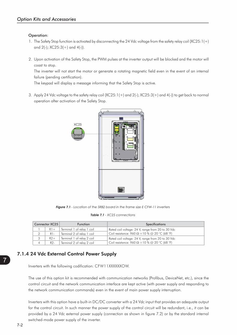
Option Kits and Accessories
7-2
7
Figure 7.1
Operation:
1. The Safety Stop function is activated by disconnecting the 24 Vdc voltage from the safety relay coil (XC25:1(+)
and 2(-); XC25:3(+) and 4(-)).
2. Upon activation of the Safety Stop, the PWM pulses at the inverter output will be blocked and the motor will
coast to stop.
The inverter will not start the motor or generate a rotating magnetic field even in the event of an internal
failure (pending certification).
The keypad will display a message informing that the Safety Stop is active.
3. Apply 24 Vdc voltage to the safety relay coil (XC25:1(+) and 2(-); XC25:3(+) and 4(-)) to get back to normal
operation after activation of the Safety Stop.
Table 7.1
Connector XC25 Function Specifications
1 R1+ Terminal 1 of relay 1 coil Rated coil voltage: 24 V, range from 20 to 30 VdcCoil resistance: 960 ±10 % @ 20 °C (68 °F)2 R1- Terminal 2 of relay 1 coil
3 R2+ Terminal 1 of relay 2 coil Rated coil voltage: 24 V, range from 20 to 30 VdcCoil resistance: 960 ±10 % @ 20 °C (68 °F)4 R2- Terminal 2 of relay 2 coil
7.1.4 24 Vdc External Control Power Supply
Inverters with the following codification: CFW11XXXXXXOW.
The use of this option kit is recommended with communication networks (Profibus, DeviceNet, etc.), since the
control circuit and the network communication interface are kept active (with power supply and responding to
the network communication commands) even in the event of main power supply interruption.
Inverters with this option have a built-in DC/DC converter with a 24 Vdc input that provides an adequate output
for the control circuit. In such manner the power supply of the control circuit will be redundant, i.e., it can be
provided by a 24 Vdc external power supply (connection as shown in figure 7.2) or by the standard internal
switched-mode power supply of the inverter.
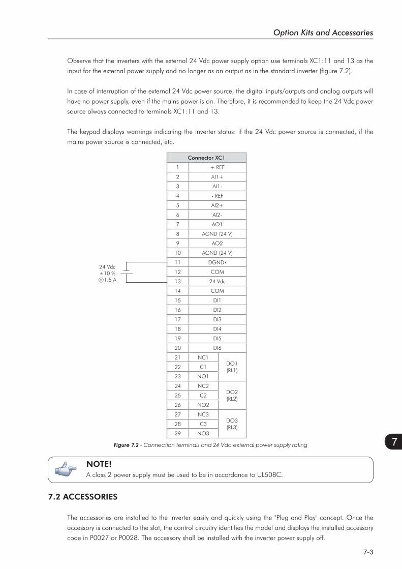
Option Kits and Accessories
7-3
7
Observe that the inverters with the external 24 Vdc power supply option use terminals XC1:11 and 13 as the
input for the external power supply and no longer as an output as in the standard inverter (figure 7.2).
In case of interruption of the external 24 Vdc power source, the digital inputs/outputs and analog outputs will
have no power supply, even if the mains power is on. Therefore, it is recommended to keep the 24 Vdc power
source always connected to terminals XC1:11 and 13.
The keypad displays warnings indicating the inverter status: if the 24 Vdc power source is connected, if the
mains power source is connected, etc.
24 Vdc±10 %@1.5 A
Figure 7.2
Connector XC1
1 + REF
2 AI1+
3 AI1-
4 - REF
5 AI2+
6 AI2-
7 AO1
8 AGND (24 V)
9 AO2
10 AGND (24 V)
11 DGND*
12 COM
13 24 Vdc
14 COM
15 DI1
16 DI2
17 DI3
18 DI4
19 DI5
20 DI6
21 NC1DO1(RL1)
22 C1
23 NO1
24 NC2DO2(RL2)
25 C2
26 NO2
27 NC3DO3(RL3)
28 C3
29 NO3
7.2 ACCESSORIES
The accessories are installed to the inverter easily and quickly using the "Plug and Play" concept. Once the
accessory is connected to the slot, the control circuitry identifies the model and displays the installed accessory
code in P0027 or P0028. The accessory shall be installed with the inverter power supply off.
NOTE!A class 2 power supply must be used to be in accordance to UL508C.
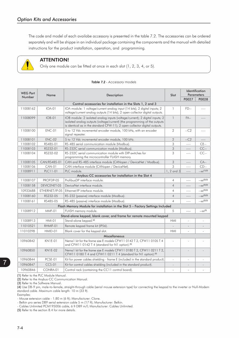
Option Kits and Accessories
7-4
7
The code and model of each availabe accessory is presented in the table 7.2. The accessories can be ordered
separately and will be shippe in an individual package containing the components and the manual with detailed
instructions for the product installation, operation, and programming.
ATTENTION!Only one module can be fitted at once in each slot (1, 2, 3, 4, or 5).
Table 7.2 - Accessory models
WEG PartNumber
Name Description SlotIdentificationParameters
P0027 P0028Control accessories for installation in the Slots 1, 2 and 3
11008162 IOA-01 IOA module: 1 voltage/current analog input (14 bits); 2 digital inputs; 2 voltage/current analog outputs (14 bits); 2 open-collector digital outputs.
1 FD-- ----
11008099 IOB-01 IOB module: 2 isolated analog inputs (voltage/current); 2 digital inputs; 2 isolated analog outputs (voltage/current) (the programming of the outputs is identical as in the standard CFW-11); 2 open-collector digital outputs.
1 FA-- ----
11008100 ENC-01 5 to 12 Vdc incremental encoder module, 100 kHz, with an encoder signal repeater.
2 --C2 ----
11008101 ENC-02 5 to 12 Vdc incremental encoder module, 100 kHz. 2 --C2 ----11008102 RS485-01 RS-485 serial communication module (Modbus). 3 ---- CE--11008103 RS232-01 RS-232C serial communication module (Modbus). 3 ---- CC--11008104 RS232-02 RS-232C serial communication module with DIP-switches for
programming the microcontroller FLASH memory.3 ---- CC--
11008105 CAN/RS485-01 CAN and RS-485 interface module (CANopen / DeviceNet / Modbus). 3 ---- CA--11008106 CAN-01 CAN interface module (CANopen / DeviceNet). 3 ---- CD--11008911 PLC11-01 PLC module. 1, 2 and 3 ---- --xx(1)(3)
Anybus-CC accessories for installation in the Slot 411008107 PROFDP-05 ProfibusDP interface module. 4 ---- --xx(2)(3)
11008158 DEVICENET-05 DeviceNet interface module. 4 ---- --xx(2)(3)
10933688 ETHERNET/IP-05 Ethernet/IP interface module. 4 ---- --xx(2)(3)
11008160 RS232-05 RS-232 (passive) interface module (Modbus). 4 ---- --xx(2)(3)
11008161 RS485-05 RS-485 (passive) interface module (Modbus). 4 ---- --xx(2)(3)
Flash Memory Module for installation in the Slot 5 – Factory Settings Included11008912 MMF-01 FLASH memory module. 5 ---- --xx(3)
Stand-alone keypad, blank cover, and frame for remote mounted keypad11008913 HMI-01 Stand-alone keypad.(4) HMI - -
11010521 RHMIF-01 Remote keypad frame kit (IP56). - - -
11010298 HMID-01 Blank cover for the keypad slot. HMI - -
Miscellaneous10960842 KN1E-01 Nema1 kit for the frame size E models CFW11 0142 T 2, CFW11 0105 T 4
and CFW11 0142 T 4 (standard for N1 option).(5)- - -
10960850 KN1E-02 Nema1 kit for the frame size E models CFW11 0180 T 2, CFW11 0211 T 2, CFW11 0180 T 4 and CFW11 0211 T 4 (standard for N1 option).(5)
- - -
10960844 PCSE-01 Kit for power cables shielding - frame E (included in the standard product). - - -
10960847 CCS-01 Kit for control cables shielding (included in the standard product). - - -
10960846 CONRA-01 Control rack (containing the CC11 control board). - - -
(1) Refer to the PLC Module Manual.(2) Refer to the Anybus-CC Communication Manual.(3) Refer to the Software Manual.(4) Use DB-9 pin, male-to-female, straight-through cable (serial mouse extension type) for connecting the keypad to the inverter or Null-Modem standard cable. Maximum cable length: 10 m (33 ft).Examples:- Mouse extension cable - 1.80 m (6 ft); Manufacturer: Clone.- Belkin pro series DB9 serial extension cable 5 m (17 ft); Manufacturer: Belkin.- Cables Unlimited PCM195006 cable, 6 ft DB9 m/f; Manufacturer: Cables Unlimited.(5) Refer to the section 8.4 for more details.

Technical Specifications
8-1
8
TECHNICAL SPECIFICATIONS
This chapter describes the technical specifications (electric and
mechanical) of the CFW-11 inverter series frame size E models.
8.1 POWER DATA
Power Supply:
Voltage tolerance: -15 % to +10 %.
Frequency: 50/60 Hz (48 Hz to 62 Hz).
Overvoltage according to Category III (EN 61010/UL 508C).
Transient voltage according to Category III.
Maximum of 60 connections per hour (1 per minute).
Typical input power factor: 0.94 in nominal conditions.
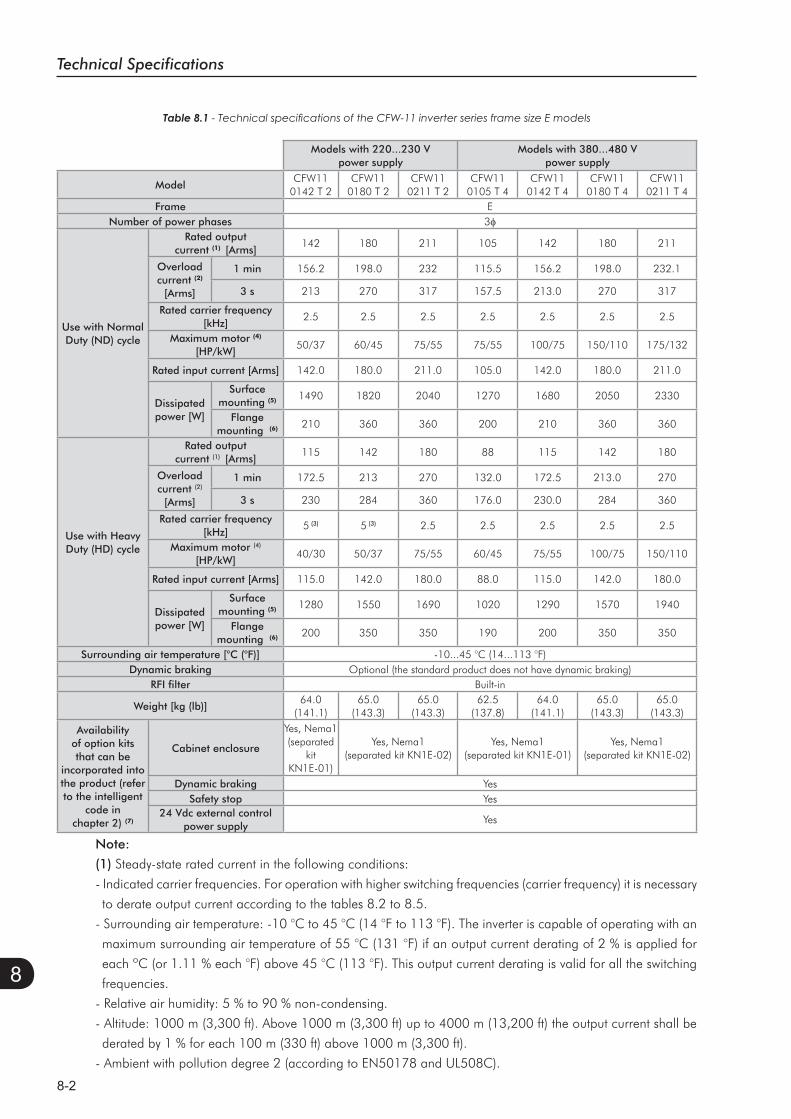
Technical Specifications
8-2
8
Note:
(1) Steady-state rated current in the following conditions:
- Indicated carrier frequencies. For operation with higher switching frequencies (carrier frequency) it is necessary
to derate output current according to the tables 8.2 to 8.5.
- Surrounding air temperature: -10 °C to 45 °C (14 °F to 113 °F). The inverter is capable of operating with an
maximum surrounding air temperature of 55 °C (131 °F) if an output current derating of 2 % is applied for
each ºC (or 1.11 % each °F) above 45 °C (113 °F). This output current derating is valid for all the switching
frequencies.
- Relative air humidity: 5 % to 90 % non-condensing.
- Altitude: 1000 m (3,300 ft). Above 1000 m (3,300 ft) up to 4000 m (13,200 ft) the output current shall be
derated by 1 % for each 100 m (330 ft) above 1000 m (3,300 ft).
- Ambient with pollution degree 2 (according to EN50178 and UL508C).
Table 8.1
Models with 220...230 V power supply
Models with 380...480 V power supply
ModelCFW11
0142 T 2CFW11
0180 T 2CFW11
0211 T 2CFW11
0105 T 4CFW11
0142 T 4CFW11
0180 T 4CFW11
0211 T 4Frame E
Number of power phases 3
Use with Normal Duty (ND) cycle
Rated output current (1) [Arms]
142 180 211 105 142 180 211
Overloadcurrent (2)
[Arms]
1 min 156.2 198.0 232 115.5 156.2 198.0 232.1
3 s 213 270 317 157.5 213.0 270 317
Rated carrier frequency [kHz]
2.5 2.5 2.5 2.5 2.5 2.5 2.5
Maximum motor (4)
[HP/kW]50/37 60/45 75/55 75/55 100/75 150/110 175/132
Rated input current [Arms] 142.0 180.0 211.0 105.0 142.0 180.0 211.0
Dissipatedpower [W]
Surfacemounting (5) 1490 1820 2040 1270 1680 2050 2330
Flangemounting (6) 210 360 360 200 210 360 360
Use with Heavy Duty (HD) cycle
Rated output current (1) [Arms]
115 142 180 88 115 142 180
Overloadcurrent (2)
[Arms]
1 min 172.5 213 270 132.0 172.5 213.0 270
3 s 230 284 360 176.0 230.0 284 360
Rated carrier frequency [kHz]
5 (3) 5 (3) 2.5 2.5 2.5 2.5 2.5
Maximum motor (4)
[HP/kW]40/30 50/37 75/55 60/45 75/55 100/75 150/110
Rated input current [Arms] 115.0 142.0 180.0 88.0 115.0 142.0 180.0
Dissipatedpower [W]
Surfacemounting (5) 1280 1550 1690 1020 1290 1570 1940
Flangemounting (6) 200 350 350 190 200 350 350
Surrounding air temperature [°C (°F)] -10...45 °C (14...113 °F)Dynamic braking Optional (the standard product does not have dynamic braking)
RFI filter Built-in
Weight [kg (lb)]64.0
(141.1)65.0
(143.3)65.0
(143.3)62.5
(137.8)64.0
(141.1)65.0
(143.3)65.0
(143.3)
Availability of option kits that can be
incorporated into the product (refer to the intelligent
code in chapter 2) (7)
Cabinet enclosure
Yes, Nema1 (separated
kitKN1E-01)
Yes, Nema1 (separated kit KN1E-02)
Yes, Nema1 (separated kit KN1E-01)
Yes, Nema1 (separated kit KN1E-02)
Dynamic braking YesSafety stop Yes
24 Vdc external control power supply
Yes
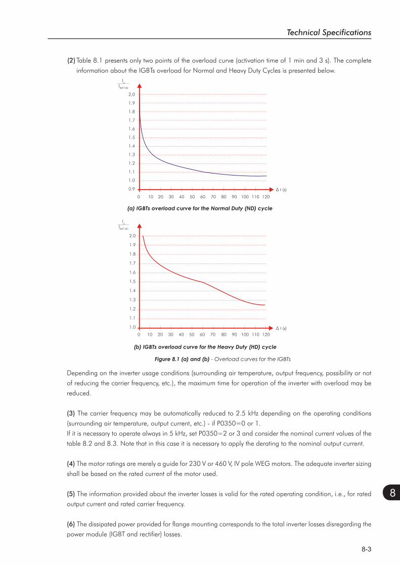
Technical Specifications
8-3
8
(2)Table 8.1 presents only two points of the overload curve (activation time of 1 min and 3 s). The complete
information about the IGBTs overload for Normal and Heavy Duty Cycles is presented below.
Figure 8.1 (a) and (b) - Overload curves for the IGBTs
2.0
1.9
1.8
1.7
1.6
1.5
1.4
1.3
1.2
1.1
1.0
0.9
0 10 20 30 40 50 60 70 80 90 100 110 120
IoIRAT ND
2.0
1.9
1.8
1.7
1.6
1.5
1.4
1.3
1.2
1.1
1.0
0 10 20 30 40 50 60 70 80 90 100 110 120
IoIRAT HD
Depending on the inverter usage conditions (surrounding air temperature, output frequency, possibility or not
of reducing the carrier frequency, etc.), the maximum time for operation of the inverter with overload may be
reduced.
(3) The carrier frequency may be automatically reduced to 2.5 kHz depending on the operating conditions
(surrounding air temperature, output current, etc.) - if P0350=0 or 1.
If it is necessary to operate always in 5 kHz, set P0350=2 or 3 and consider the nominal current values of the
table 8.2 and 8.3. Note that in this case it is necessary to apply the derating to the nominal output current.
(4) The motor ratings are merely a guide for 230 V or 460 V, IV pole WEG motors. The adequate inverter sizing
shall be based on the rated current of the motor used.
(5) The information provided about the inverter losses is valid for the rated operating condition, i.e., for rated
output current and rated carrier frequency.
(6) The dissipated power provided for flange mounting corresponds to the total inverter losses disregarding the
power module (IGBT and rectifier) losses.
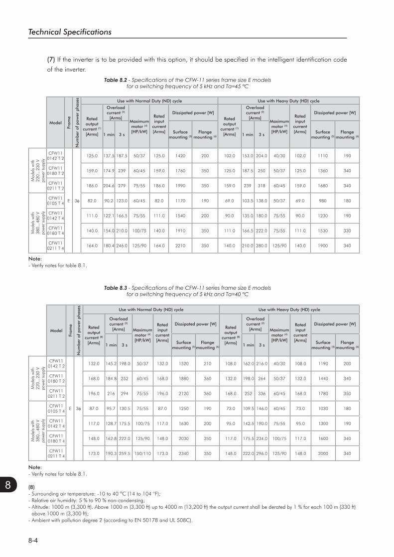
Technical Specifications
8-4
8
(7) If the inverter is to be provided with this option, it should be specified in the intelligent identification code
of the inverter.
Table 8.2
Table 8.3
Model
Fram
e
Num
ber
of p
ower
pha
ses
Use with Normal Duty (ND) cycle Use with Heavy Duty (HD) cycle
Rated output
current (1) [Arms]
Overloadcurrent (2)
[Arms]Maximummotor (4)
[HP/kW]
Rated input
current[Arms]
Dissipated power [W]Rated output
current (1) [Arms]
Overloadcurrent (2)
[Arms]Maximummotor (4)
[HP/kW]
Rated input
current[Arms]
Dissipated power [W]
1 min 3 sSurface
mounting (5)Flange
mounting (6) 1 min 3 sSurface
mounting (5)Flange
mounting (6)
Mod
els
with
22
0...2
30 V
pow
er s
uppl
y
CFW110142 T 2
E 3
125.0 137.5 187.5 50/37 125.0 1420 200 102.0 153.0 204.0 40/30 102.0 1110 190
CFW110180 T 2
159.0 174.9 239 60/45 159.0 1760 350 125.0 187.5 250 50/37 125.0 1360 340
CFW110211 T 2
186.0 204.6 279 75/55 186.0 1990 350 159.0 239 318 60/45 159.0 1680 340
Mod
els
with
38
0...4
80 V
pow
er s
uppl
y
CFW110105 T 4
82.0 90.2 123.0 60/45 82.0 1170 190 69.0 103.5 138.0 50/37 69.0 980 180
CFW110142 T 4
111.0 122.1 166.5 75/55 111.0 1540 200 90.0 135.0 180.0 75/55 90.0 1230 190
CFW110180 T 4
140.0 154.0 210.0 100/75 140.0 1910 350 111.0 166.5 222.0 75/55 111.0 1530 330
CFW110211 T 4
164.0 180.4 246.0 125/90 164.0 2210 350 140.0 210.0 280.0 125/90 140.0 1900 340
Model
Fram
e
Num
ber
of p
ower
pha
ses
Use with Normal Duty (ND) cycle Use with Heavy Duty (HD) cycle
Rated output
current (8) [Arms]
Overloadcurrent (2)
[Arms] Maximummotor (4)
[HP/kW]
Rated input
current[Arms]
Dissipated power [W]Rated output
current (8) [Arms]
Overloadcurrent (2)
[Arms] Maximummotor (4)
[HP/kW]
Rated input
current[Arms]
Dissipated power [W]
1 min 3 sSurface
mounting (5)Flange
mounting (6) 1 min 3 sSurface
mounting (5)Flange
mounting (6)
Mod
els
with
22
0...2
30 V
pow
er s
uppl
y
CFW110142 T 2
E 3
132.0 145.2 198.0 50/37 132.0 1520 210 108.0 162.0 216.0 40/30 108.0 1190 200
CFW110180 T 2
168.0 184.8 252 60/45 168.0 1880 360 132.0 198.0 264 50/37 132.0 1440 340
CFW110211 T 2
196.0 216 294 75/55 196.0 2120 360 168.0 252 336 60/45 168.0 1780 350
Mod
els
with
38
0...4
80 V
pow
er s
uppl
y
CFW110105 T 4
87.0 95.7 130.5 75/55 87.0 1250 190 73.0 109.5 146.0 60/45 73.0 1030 180
CFW110142 T 4
117.0 128.7 175.5 100/75 117.0 1630 200 95.0 142.5 190.0 75/55 95.0 1300 190
CFW110180 T 4
148.0 162.8 222.0 125/90 148.0 2030 350 117.0 175.5 234.0 100/75 117.0 1600 340
CFW110211 T 4
173.0 190.3 259.5 150/110 173.0 2340 350 148.0 222.0 296.0 125/90 148.0 2000 340
Note:- Verify notes for table 8.1.
(8)- Surrounding air temperature: -10 to 40 ºC (14 to 104 °F);- Relative air humidity: 5 % to 90 % non-condensing;- Altitude: 1000 m (3,300 ft). Above 1000 m (3,300 ft) up to 4000 m (13,200 ft) the output current shall be derated by 1 % for each 100 m (330 ft)
above 1000 m (3,300 ft);- Ambient with pollution degree 2 (according to EN 50178 and UL 508C).
Note:- Verify notes for table 8.1.
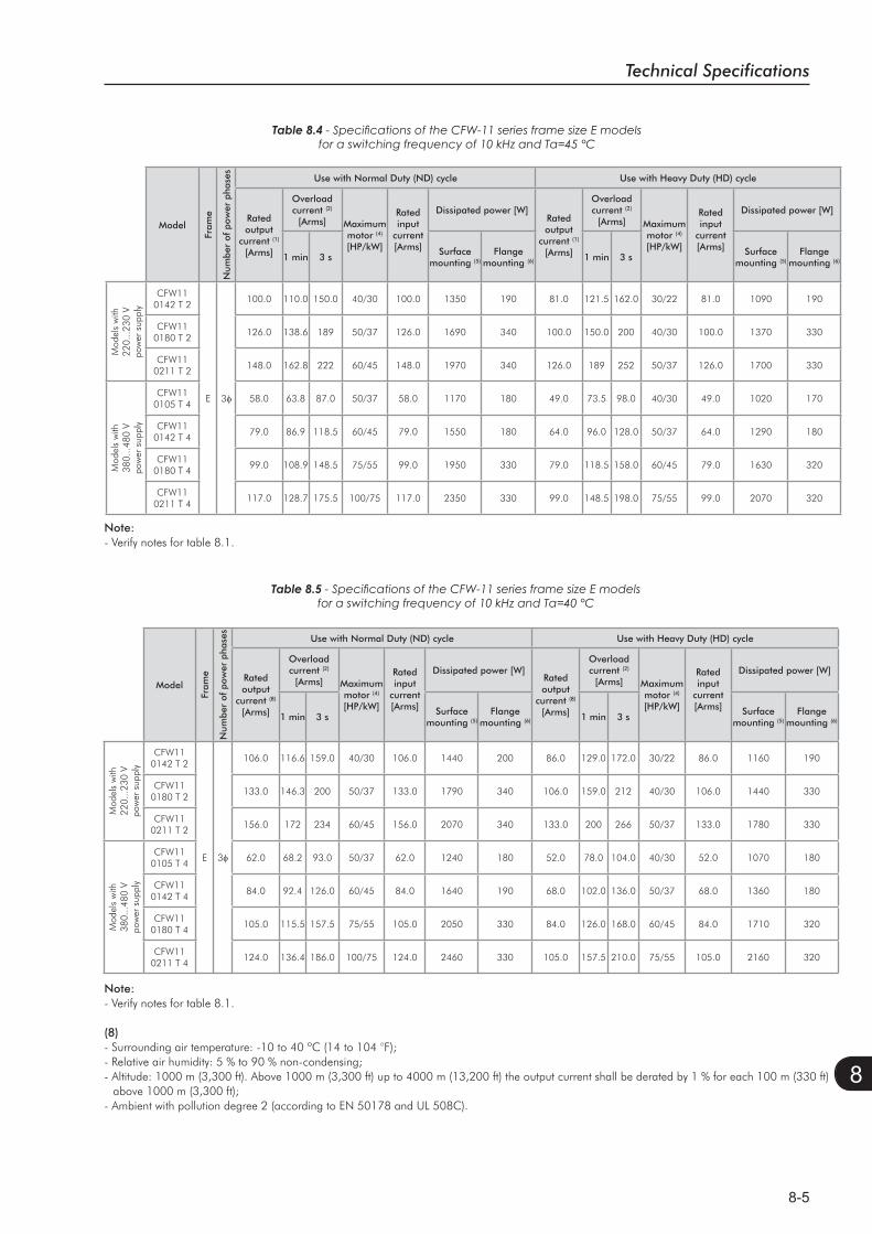
Technical Specifications
8-5
8
Table 8.4
Model
Fram
e
Num
ber
of p
ower
pha
ses
Use with Normal Duty (ND) cycle Use with Heavy Duty (HD) cycle
Rated output
current (1) [Arms]
Overloadcurrent (2)
[Arms] Maximummotor (4)
[HP/kW]
Rated input
current[Arms]
Dissipated power [W]Rated output
current (1) [Arms]
Overloadcurrent (2)
[Arms] Maximummotor (4)
[HP/kW]
Rated input
current[Arms]
Dissipated power [W]
1 min 3 sSurface
mounting (5)Flange
mounting (6) 1 min 3 sSurface
mounting (5)Flange
mounting (6)
Mod
els
with
22
0...2
30 V
pow
er s
uppl
y
CFW110142 T 2
E 3
100.0 110.0 150.0 40/30 100.0 1350 190 81.0 121.5 162.0 30/22 81.0 1090 190
CFW110180 T 2
126.0 138.6 189 50/37 126.0 1690 340 100.0 150.0 200 40/30 100.0 1370 330
CFW110211 T 2
148.0 162.8 222 60/45 148.0 1970 340 126.0 189 252 50/37 126.0 1700 330
Mod
els
with
38
0...4
80 V
pow
er s
uppl
y
CFW110105 T 4
58.0 63.8 87.0 50/37 58.0 1170 180 49.0 73.5 98.0 40/30 49.0 1020 170
CFW110142 T 4
79.0 86.9 118.5 60/45 79.0 1550 180 64.0 96.0 128.0 50/37 64.0 1290 180
CFW110180 T 4
99.0 108.9 148.5 75/55 99.0 1950 330 79.0 118.5 158.0 60/45 79.0 1630 320
CFW110211 T 4
117.0 128.7 175.5 100/75 117.0 2350 330 99.0 148.5 198.0 75/55 99.0 2070 320
Note:- Verify notes for table 8.1.
Table 8.5
Model
Fram
e
Num
ber
of p
ower
pha
ses
Use with Normal Duty (ND) cycle Use with Heavy Duty (HD) cycle
Rated output
current (8) [Arms]
Overloadcurrent (2)
[Arms] Maximummotor (4)
[HP/kW]
Rated input
current[Arms]
Dissipated power [W]Rated output
current (8) [Arms]
Overloadcurrent (2)
[Arms] Maximummotor (4)
[HP/kW]
Rated input
current[Arms]
Dissipated power [W]
1 min 3 sSurface
mounting (5)Flange
mounting (6) 1 min 3 sSurface
mounting (5)Flange
mounting (6)
Mod
els
with
22
0...2
30 V
pow
er s
uppl
y
CFW110142 T 2
E 3
106.0 116.6 159.0 40/30 106.0 1440 200 86.0 129.0 172.0 30/22 86.0 1160 190
CFW110180 T 2
133.0 146.3 200 50/37 133.0 1790 340 106.0 159.0 212 40/30 106.0 1440 330
CFW110211 T 2
156.0 172 234 60/45 156.0 2070 340 133.0 200 266 50/37 133.0 1780 330
Mod
els
with
38
0...4
80 V
pow
er s
uppl
y
CFW110105 T 4
62.0 68.2 93.0 50/37 62.0 1240 180 52.0 78.0 104.0 40/30 52.0 1070 180
CFW110142 T 4
84.0 92.4 126.0 60/45 84.0 1640 190 68.0 102.0 136.0 50/37 68.0 1360 180
CFW110180 T 4
105.0 115.5 157.5 75/55 105.0 2050 330 84.0 126.0 168.0 60/45 84.0 1710 320
CFW110211 T 4
124.0 136.4 186.0 100/75 124.0 2460 330 105.0 157.5 210.0 75/55 105.0 2160 320
Note:- Verify notes for table 8.1.
(8)- Surrounding air temperature: -10 to 40 ºC (14 to 104 °F);- Relative air humidity: 5 % to 90 % non-condensing;- Altitude: 1000 m (3,300 ft). Above 1000 m (3,300 ft) up to 4000 m (13,200 ft) the output current shall be derated by 1 % for each 100 m (330 ft)
above 1000 m (3,300 ft);- Ambient with pollution degree 2 (according to EN 50178 and UL 508C).
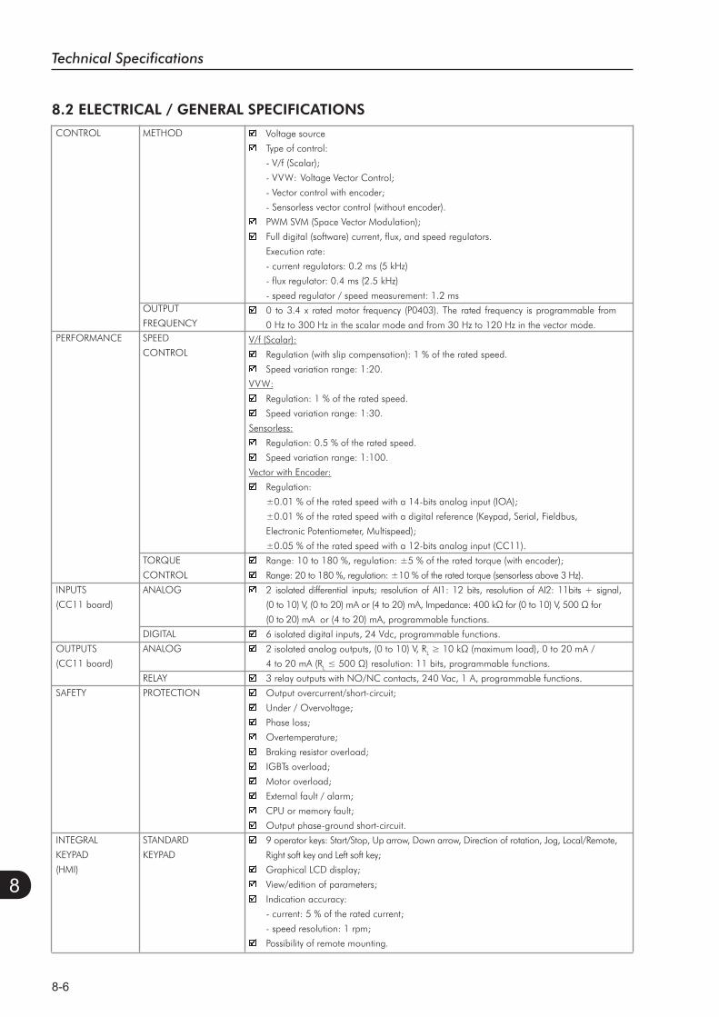
Technical Specifications
8-6
8
8.2 ELECTRICAL / GENERAL SPECIFICATIONS
Voltage source
Type of control:
- V/f (Scalar);
- VVW: Voltage Vector Control;
- Vector control with encoder;
- Sensorless vector control (without encoder).
PWM SVM (Space Vector Modulation);
Full digital (software) current, flux, and speed regulators.
Execution rate:
- current regulators: 0.2 ms (5 kHz)
- flux regulator: 0.4 ms (2.5 kHz)
- speed regulator / speed measurement: 1.2 ms
0 to 3.4 x rated motor frequency (P0403). The rated frequency is programmable from
0 Hz to 300 Hz in the scalar mode and from 30 Hz to 120 Hz in the vector mode.
V/f (Scalar):
Regulation (with slip compensation): 1 % of the rated speed.
Speed variation range: 1:20.
VVW:
Regulation: 1 % of the rated speed.
Speed variation range: 1:30.
Sensorless:
Regulation: 0.5 % of the rated speed.
Speed variation range: 1:100.
Vector with Encoder:
Regulation:
±0.01 % of the rated speed with a 14-bits analog input (IOA);
±0.01 % of the rated speed with a digital reference (Keypad, Serial, Fieldbus,
Electronic Potentiometer, Multispeed);
±0.05 % of the rated speed with a 12-bits analog input (CC11).
Range: 10 to 180 %, regulation: ±5 % of the rated torque (with encoder);
Range: 20 to 180 %, regulation: ±10 % of the rated torque (sensorless above 3 Hz).
2 isolated differential inputs; resolution of AI1: 12 bits, resolution of AI2: 11bits + signal,
(0 to 20) mA or (4 to 20) mA, programmable functions.
6 isolated digital inputs, 24 Vdc, programmable functions.
2 isolated analog outputs, (0 to 10) V, RL
4 to 20 mA (RL
3 relay outputs with NO/NC contacts, 240 Vac, 1 A, programmable functions.
Output overcurrent/short-circuit;
Under / Overvoltage;
Phase loss;
Overtemperature;
Braking resistor overload;
IGBTs overload;
Motor overload;
External fault / alarm;
CPU or memory fault;
Output phase-ground short-circuit.
9 operator keys: Start/Stop, Up arrow, Down arrow, Direction of rotation, Jog, Local/Remote,
Right soft key and Left soft key;
Graphical LCD display;
View/edition of parameters;
Indication accuracy:
- current: 5 % of the rated current;
- speed resolution: 1 rpm;
Possibility of remote mounting.
CONTROL METHOD
OUTPUT
FREQUENCY
PERFORMANCE SPEED
CONTROL
TORQUE
CONTROL
INPUTS ANALOG
(CC11 board)
DIGITAL
OUTPUTS ANALOG
(CC11 board)
RELAY
SAFETY PROTECTION
INTEGRAL STANDARD
KEYPAD KEYPAD
(HMI)

Technical Specifications
8-7
8
8.2.1 Codes and Standards
UL 508C - Power conversion equipment.
UL 840 - Insulation coordination including clearances and creepage distances for electrical
equipment.
EN61800-5-1 - Safety requirements electrical, thermal and energy.
EN 50178 - Electronic equipment for use in power installations.
EN 60204-1 - Safety of machinery. Electrical equipment of machines. Part 1: General
requirements.
Note: The final assembler of the machine is responsible for installing an safety stop device
and a supply disconnecting device.
EN 60146 (IEC 146) - Semiconductor converters.
EN 61800-2 - Adjustable speed electrical power drive systems - Part 2: General
requirements - Rating specifications for low voltage adjustable frequency AC power drive
systems.
EN 61800-3 - Adjustable speed electrical power drive systems - Part 3: EMC product
standard including specific test methods.
EN 55011 - Limits and methods of measurement of radio disturbance characteristics of
industrial, scientific and medical (ISM) radio-frequency equipment.
CISPR 11 - Industrial, scientific and medical (ISM) radio-frequency equipment -
Electromagnetic disturbance characteristics - Limits and methods of measurement.
EN 61000-4-2 - Electromagnetic compatibility (EMC) - Part 4: Testing and measurement
techniques - Section 2: Electrostatic discharge immunity test.
EN 61000-4-3 - Electromagnetic compatibility (EMC) - Part 4: Testing and measurement
techniques - Section 3: Radiated, radio-frequency, electromagnetic field immunity test.
EN 61000-4-4 - Electromagnetic compatibility (EMC) - Part 4: Testing and measurement
techniques - Section 4: Electrical fast transient/burst immunity test.
EN 61000-4-5 - Electromagnetic compatibility (EMC) - Part 4: Testing and measurement
techniques - Section 5: Surge immunity test.
EN 61000-4-6 - Electromagnetic compatibility (EMC)- Part 4: Testing and measurement
techniques - Section 6: Immunity to conducted disturbances, induced by radio-frequency
fields.
EN 60529 - Degrees of protection provided by enclosures (IP code).
UL 50 - Enclosures for electrical equipment.
SAFETY
STANDARDS
ELECTROMAGNETIC
COMPATIBILITY (EMC)
MECHANICAL
STANDARDS
8.2 ELECTRICAL / GENERAL SPECIFICATIONS (cont.)Inverters without Nema1 kit.
Inverters with Nema1 kit (KN1E-01 or KN1E-02).
Rear part of the inverter (external part for flange mounting).
USB standard Rev. 2.0 (basic speed);
Type B (device) USB plug;
Interconnection cable: standard host/device shielded USB cable.
ENCLOSURE IP20
NEMA1/IP20
IP54
PC CONNECTION USB CONNECTOR
FOR INVERTER
PROGRAMMING
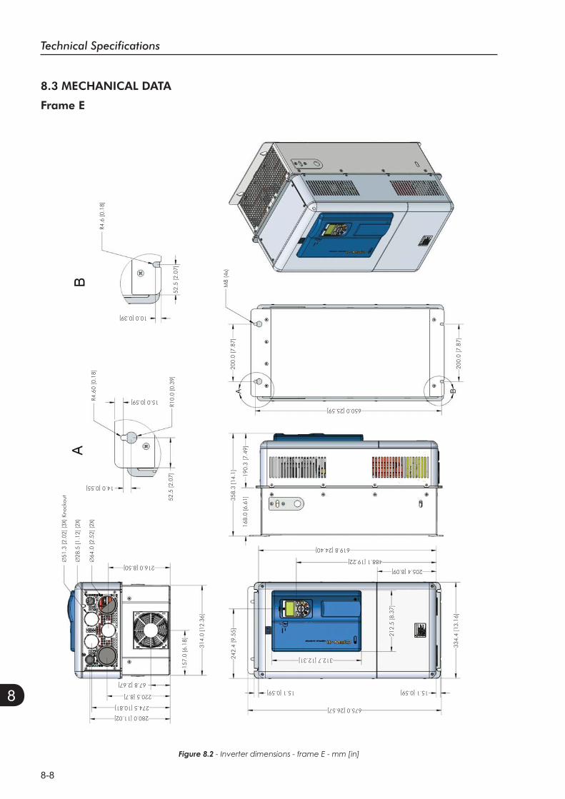
Technical Specifications
8-8
8
8.3 MECHANICAL DATA
Frame E
Figure 8.2 - Inverter dimensions - frame E - mm [in]
R4.6
[0.1
8]R4
.60
[0.1
8]
52.5
[2.0
7]
M8
(4x)
10.0 [0.39]
15.0 [0.59]
14.0 [0.55]
216.0 [8.50]
280.0 [11.02]675.0 [26.57]
15.1 [0.59]
205.4 [8.09]
488.1 [19.22]
619.8 [24.40]
650.0 [25.59]
312.7 [12.31]
15.1 [0.59]
274.5 [10.81]
220.5 [8.7]
67.8 [2.67]
R10.
0 [0
.39]
52.5
[2.0
7]
314.
0 [1
2.36
]
242.
4 [9
.55]
358.
3 [1
4.1]
200.
0 [7
.87]
200.
0 [7
.87]
168.
0 [6
.61]
190.
3 [7
.49]
157.
0 [6
.18]
51.3
[2.0
2] (3
X) K
nock
out
28.5
[1.1
2] (2
X)
64.0
[2.5
2] (2
X)
212.
5 [8
.37]
334.
4 [1
3.16
]
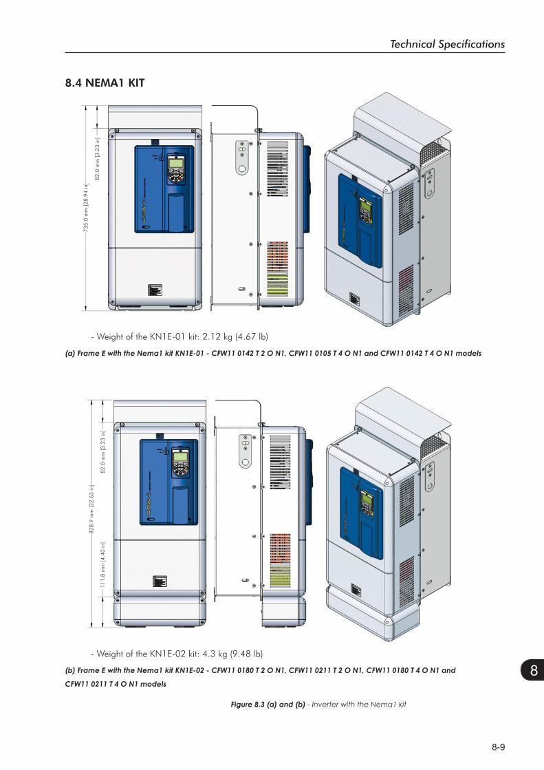
Technical Specifications
8-9
8
828.
9 m
m [3
2.63
in]
111.
8 m
m [4
.40
in]
82.0
mm
[3.2
3 in
]
735.
0 m
m [2
8.94
in]
82.0
mm
[3.2
3 in
]
- Weight of the KN1E-02 kit: 4.3 kg (9.48 lb)
Figure 8.3 (a) and (b) - Inverter with the Nema1 kit
8.4 NEMA1 KIT
- Weight of the KN1E-01 kit: 2.12 kg (4.67 lb)