Embed Size (px)
Citation preview

Frequency-Domain Range Data Registration for 3-D Space
Modeling in Robotic Applications
By Phillip Curtis

What is Registration?
• Registration is the act of making an image of an object from one point of view, match an image of the same object from a different point of view.
RImage 1
RImage 2
Bounding Box 1
Bounding Box 2
QIm1 Im2QIm1 BB1
QIm2 BB2
QBB1 BB2

What is Needed?
• A registration technique for robotics applications must be:– Quick, with a low computational burden– Flexible (precision adjusted to task)– Accurate– Scalable

Registration Prior Art
• Classical approaches– Three Point Problem
• Requires direct knowledge of point correspondents and 3-D spatial locations: P2=Q*P1, solve for Q
– Iterative solutions• Classic iterative closest point (ICP) algorithm by
Besl and McKay [1]. – Most research in the field of range image registration is
centred on modifications on the ICP approach[1] P.J. Besl, N.D. McKay, “A Method for Registration of 3-D Shapes”, IEEE Transactions on Pattern Analysis and Machine Intelligence , Vol. 14, pp. 239-256, Feb. 1992.

ICP
• Besl and McKay’s ICP Algorithm– 1st : match points between images using the
criterion of closest point– 2nd : determine the optimal registration for that
match by first estimating the rotation, then the translation
– 3rd : rotate the 1st image by the estimation– 4th : Repeat the 1st, 2nd, and 3rd steps until the
error delta between iterations is small enough

ICP
• Advantages– Allows for arbitrary data sampling structures– Simple and precise
• Disadvantages– Tends toward local minima, unless a precise
initial estimate is used– Slow due to its matching algorithm (N-
squared)

Frequency Domain Registration
• Well known in 2-D registration• Extended to 3-D by Lucchese et al. [2]
– Takes advantage of the fact that the Fourier transform decouples the estimation of the rotational parameters from that of the translational parameters
– Uses correlation and geometric projection techniques to extract rotational and translational parameters
[2] L. Lucchese, G. Doretto, G.M. Cortelazzo, “A Frequency Domain Technique for Range Data Registration”, IEEE Transactions on Pattern Analysis and Machine Intelligence, Vol. 24, No. 11, pp. 1468-1484, Nov. 2002.

Frequency Domain Registration
• Advantages– No initial estimate– No matching of features required– Avoid local minima solutions that are inherent
in ICP
• Disadvantages– Luccese et al. require many transformations of
the data (FFT and correlation histograms) to achieve results

Frequency Domain Benefits
• The frequency domain allows for a low computational burden, due to the availability of the Fast Fourier Transform
• The frequency domain techniques have the ability to scale well to an increase in dataset size
• Precision can be adjusted by changing the resolution.

Frequency Domain Registration
• Fourier Transform allows for the effective segregation of the rotation parameters from the translation parameters.
TnRn
21 ImImFourier Transform MTkRj
T
ekFkRF
2ImIm 12
kFkR
12 ImImF MTkRkFkRT
2F12 ImIm
Magnitude Phase

Determining The Axis of Rotation
• All objects which rotate have an axis of rotation.• By eliminating the effects of the translation parameters when
two frequency domain magnitude images are subtracted, the axis of rotation can be found by determining the zero line through the frequency origin, since this line is the only constant between the two images.
Axis of Rotation Axis of Rotation

Determining the Angle of Rotation
• The angle of rotation can be determined via a minimum sum of the difference of squares search of possible rotation values about the axis of rotation.
• Due to the Hermitian symmetry property of the Fourier transform, there are two possible rotation angles, separated by 180°.
Rotation by 45° or by -135°?

Solution Selection
• A phase correlation between the first image, and the second image derotated by both solutions is used to determine the proper solution. The proper solution will yield a more impulse-like space function.
Im2aIm1 Im2
b
Correlation of Im1
and Im2a
Correlation of Im1
and Im2b
Plot of Im1 Plot of Im2a Plot of Im2
b
n n n
n n

Estimation of Translation
• The location of the impulse of the phase correlation corresponds to the estimate of the translation parameters
Correlation of Im1 and Im2
a
nT=Location

What Needed to be Done
• Lucchese et al. provide a nice rigorous start to frequency domain registration, but to be practical for robotics applications the following must be improved– A more efficient method for the estimation of the axis
of rotation– A more efficient and flexible method for the
estimation of the angle of rotation– Handle images with multiple properties (colour,
texture, etc), in addition to range

Descretisation of Data
• Apply continuously positioned data to a discrete grid for the FFT– Need to add ‘volume’ to
each point, so that the energy is captured, prevent impulsive effects, and aliasing
– Cubic voxels to prevent scaling factors
– Minimize the data spaceD
-3
D-1
D-2
RBB
M1 = 17M2 = 18M3 = 7
Bounding Box
Dimension Sizes
-1 +10

Determining the Axis of Rotation
• Minimize calculation time, while maintaining accuracy comparable to Lucchese et al.
• Solution was to develop the normalised percentage difference equation (eq. 18) to find the difference between F-D images
• Use a moving window search technique to find the axis

Determine the Angle of Rotation
• Lucchese et al. use a correlation histogram technique using the projections of rotated then re-transformed data to estimate the angle of rotation– Huge computational penalty
• This thesis uses a coarse to fine minimum of least squares iterative approach
-π,π
π/3
7π/1813π/36

Solution Selection
• Observations of Correct solution vs. complementary solution– Correct solution is more
impulsive, and that impulse is higher than the average energy
• Uses peak energy / average energy measure along the projections of each dimension

Translation Estimate
• The solution with the highest ratio “wins”• The location of the maximal peak in the winning
solution is the estimate of the translation parameters

Experimental Setup
• Used both simulated data and real data acquired– Simulated data from
Dr. P. Payeur’s simulator
– Real Data from robotic range sensing system developed primarily for this thesis
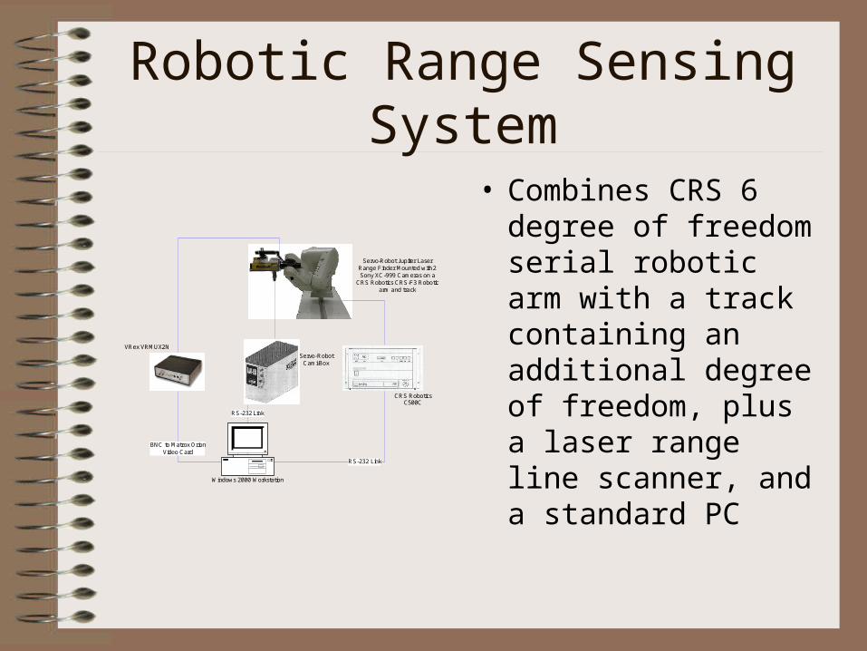
Robotic Range Sensing System
• Combines CRS 6 degree of freedom serial robotic arm with a track containing an additional degree of freedom, plus a laser range line scanner, and a standard PC
Windows 2000 Workstation
RS-232 Link
RS-232 Link
Servo-Robot Cami-Box
CRS Robotics C500C
Servo-Robot Jupiter Laser Range Finder Mounted with 2 Sony XC-999 Cameras on a
CRS Robotics CRS-F3 Robotic arm and track
BNC to Matrox OrionVideo Card
VRex VRMUX2N

Robotic Range Sensing System
• Used standard RS-232 serial communications protocol and Windows 2000 Win32 API to develop control and acquisition software.
• Inverse kinematics was modified from that developed by W.M. Keck virtual factory lab.

Robotic Range Sensing System
• Cut down on number of tools required to acquire data
• Saves data in many formats used by members in VIVA lab
• Repeatable and quick (64 lines from 3 different perspectives takes about half an hour)
• Expandable code base

Test Data
• Used both simulated data sets and real data sets– The simulated house frame was selected to evaluate the performance of
the algorithm using objects with a high degree of symmetry– The real house frame data was selected to see how the algorithm
performed under “real” data vs. simulated data.

Test Data
– Simulated computer setup was used to evaluate performance with occlusions
– Skewed planar surfaces were used to evaluate overlap performance
x
y
z
x
z
y
z
y
x

Some Results
• Histogram of rotation error of simulated house frame (top) and real house frame (bottom) data sets.
Division of Results according to Rotation Error (FFT=128, Matches=1600, DataSet=maison_simul_xx)
0
10
20
30
40
50
60
70
80
90
100
0.0 to 0.5 0.5 to 1.0 1.0 to 1.5 1.5 to 2.0 2.0 to 2.5 2.5 to 3.0
Rotation Error
Sinc
Rect
Triangle
Gaussian
RaisedCos
InverseDecay
Division of Results according to Rotation Error (FFT=128, Matches=1600, DataSet=house_ actual_ xx)
0
10
20
30
40
50
60
70
80
90
100
0.0 to 0.5 0.5 to 1.0 1.0 to 1.5 1.5 to 2.0 2.0 to 2.5 2.5 to 3.0
Rotation Error
Sinc
Rect
Triangle
Gaussian
RaisedCos
InverseDecay

Some Results
• Selected registration point clouds of registered data sets (top simulated house frame, bottom is real house frame)
Front View Top View

Some Results
• Histogram of rotation error (top) and selected registration point cloud (bottom) for simulated computer data sets
Division of Results according to Rotation Error (FFT=32, Matches=800, DataSet=CPU_ xx)
0
50
100
150
200
250
300
350
0.0 to 0.5 0.5 to 1.0 1.0 to 1.5 1.5 to 2.0 2.0 to 2.5 2.5 to 3.0
Rotation Error
Sinc
Rect
Triangle
Gaussian
RaisedCos
InverseDecay
Front View Top View

Some Results
• Execution times of the frequency domain registration algorithm developed in this thesis, compared to that of ICP
Sinc Gaussian Rectangular Triangular RaisedCos InverseDecay ICP
FFT=16, Matches=400,Simulated House 5.277 5.2535 5.0387 5.3612 5.0235 5.0624 52.0081
FFT=128, Matches=1600,Simulated House 27.681 25.8461 25.8061 25.7468 25.8349 25.7467 52.0081
FFT=16, Matches=400,Simulated CPU 7.06892 6.948852 6.80956633 6.825179 6.8507398 6.82522959 247.1992
FFT=128, Matches=1600,Simulated CPU 20.7805 20.86643 20.7528189 20.77778 22.109541 21.6756633 247.1992

Results
• The implementation as described in this thesis is accurate, and flexible
• Have improved computational efficiency, compared to Lucchese et al. without observable loss of accuracy
• More scalable than ICP (execution time is faster and does not grow as rapidly as ICP)
• Have added in the capability for enhanced data sets containing colour in addition for range data (untested)

Conclusion
• Proposed, implemented, and tested an automatic registration estimation algorithm that:– does not require human intervention– does not require an initial estimate– is independent of the geometry of the object– provides the framework for the multi-dimensional,
multi-property data registration– is scalable with regards to data set size, and desired
precision– is more efficient than that of Lucchese et al. and of
Besl and McKay.

Conclusion
• The following innovations were contributed to the area of frequency domain registration research– More computationally efficient difference equation for
calculating the difference between frequency domain magnitude images
– Moving window to determine axis of rotation– Coarse to fine approach to determine the angle of
rotation– Development of a robotic range sensing system

Future Work
• Improve solution selection mechanism
• Investigate other transform domains
• Test with enhanced data sets containing multiple data attributes
• Develop the mathematical frame work for higher dimensional registration using the axis of rotation model

Resulting Research Publications
• P. Curtis, P. Payeur, “An Integrated Robotic Laser Range Sensing System for Automatic Mapping of Wide Workspaces”, Proceedings of the IEEE Canadian Conference on Electrical And Computer Engineering, Vol. 2, pp. 1135-1138, May 2004.
• P. Curtis, C.S. Yang, P. Payeur, "An Integrated Robotic Multi-Modal Sensing System", Proceedings of the IEEE International Instrumentation and Measurement Technology Conference, pp. 1991-1996, Ottawa, ON, 2005.
• C.S. Yang, P. Curtis, P. Payeur, "Calibration of an Integrated Robotic Multi-Modal Range Scanner", submitted to IEEE Transactions on Instrumentation and Measurement, 2005.
• P. Curtis, P. Payeur, “A Frequency Domain Approach to Registration in 3-D Space”, submitted to IEEE International Instrumentation and Measurement Technology Conference, Oct. 2005.
• P. Curtis, P. Payeur, “Registering 3-D Data with Multiple Properties using a Frequency Domain Approach“, in preparation for IEEE Transactions on Pattern Analysis and Machine Intelligence.

Questions
![PHILLIP FUTURES SDN BHD (362533-U)...[4] 1. BACKGROUND INFORMATION ON PHILLIP FUTURES SDN BHD Phillip Futures Sdn Bhd (Company Registration No. 362533-U) (“Phillip Futures”) was](https://img.pdfslide.us/doc/110x75/611b8c3291dd2b1bed65ee03/phillip-futures-sdn-bhd-362533-u-4-1-background-information-on-phillip.jpg)