Embed Size (px)
Citation preview
Reprinted from Ultrasonic Instruments and Devices 01999, Academic Press, Inc. The book is copyrighted, however this chapter is not, because the authors are employees of the U.S. Government and performed this work as part of their official duties. The work is therefore not subject to copyright protection.
-7-
Frequency Control Devices
JOHN R. WG and ARTHUR BALLATO ‘US. Army Communications --Electronics Command, Fort Monmouth, New Jersey
I. Introduction ......................................... 637 II. Applications. ........................................ 638
A. Communication Systems. ............................... 640 B. Navigation, ....................................... 644 C. Surveillance. ...................................... 646 D. Identification-Friend-or-Foe (IFF) Systems. ..................... 647 E. Electronic Warfare ................................... 648
. F. Missile Guidance. ................................... 649 G. Battery Consumption. ................................. 649 H. Survivability under Radiation and High Acceleration. ............... 650 I. Logistics Costs ..................................... 650
III. Frequency Control Device Fundamentals. ........................ 650 A. Crystal Oscillators ................................... 651 B. Oscillator Categories .................................. 664 C. Oscillator Circuit Types ................................ 666 D. Oscillator Instabilities ................................. 667 E. Oscillator Comparison and Selection ......................... 689 . Failure Mechanisms .................................. 694 G. Specifications, Standards, Terms and Detkutions .................. 694
TV: RelatedDevices. ...................................... 695 A. Crystal Filters. ..................................... 695 B. Sensors and Transducers. ............................... 696
V For Further Reading. .................................... 697 References. ......................................... 697
I. Introduction
Frequency control devices provide the precise time and frequency on which modern electronics depends. A vibrating quartz crystal, i.e., a quartz reso- nator, is the “heart” of nearly all frequency control devices. Quartz clocks provide accurate time ‘and quartz oscillators are the sources of precise frequency.
The futldamental roles these devices play in the modern world can be seen by considering what would happen if all the quartz crystals in the world suddenly stopped vibrating. All modem communication systems (telephones,
637
638 John R. Vig and Arthur Ballato
radios, TV stations, air traffic control systems, etc.) would stop functioning, all but the oldest transportation systems (automobiles, trucks, airplanes) would cease operating, and all computers would stop. The consequences would be catastrophic.
Time is important not only for the daily schedules of human beings, but also, for example, for determining the sequence of events that take place inside computers, and for time-tagging the information that flows through communication systems. Frequency sources are essential for determining the frequencies of radio and TV transmissions, radar systems, communication and navigation systems, etc.
Frequency control technology took a great leap forward in the 1920s when quartz was first utilized to realize crystal resonators for the stabilization of oscillators, thereby launching the field of modem frequency control. With the introduction of quartz control, timekeeping moved from the sun and stars to small, man-made sources that exceeded astronomy-based references in stability. Since then, the applications of devices based on quartz have expanded dramatically. The quartz resonator has continued to evolve to become a device capable of precision one million times greater than the original. It also serves as the “flywheel” in atomic frequency standards. Atomic standards make frequency the most accurate entity known.
Of the man-grown single crystals, quartz is second to silicon in quantity grown. About 2500 to 3000 tons of quartz crystals are grown per year (about three to four times as much silicon is grown). The major applications are oscillators for clocks and frequency sources. Other important applications are sensors, and filters used for frequency selection. About 2 x lo9 bulk acoustic wave (BAW) quartz resonators, and several hundred million quartz surface acoustive wave (SAW) devices are manufactured annually.
II. Applications
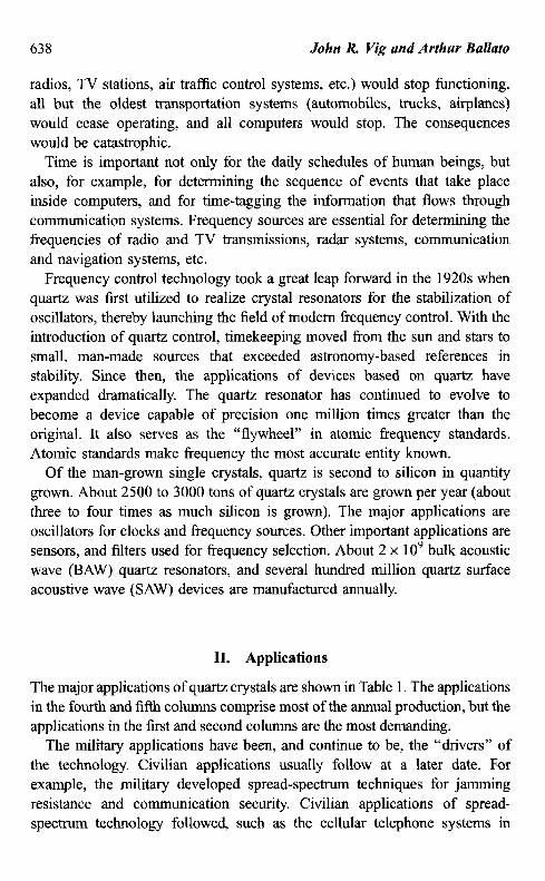
The major applications of quartz crystals are shown in Table 1. The applications in the fourth and fifth columns comprise most of the annual production, but the applications in the fist and second columns are the most demanding.
The military applications have been, and continue to be, the “drivers” of the technology. Civilian applications usuaIly follow at a later date. For example, the military developed spread-spectrum techniques for jamming resistance and communication security. Civilian applications of spread- spectrum technology followed, such as the cellular telephone systems in
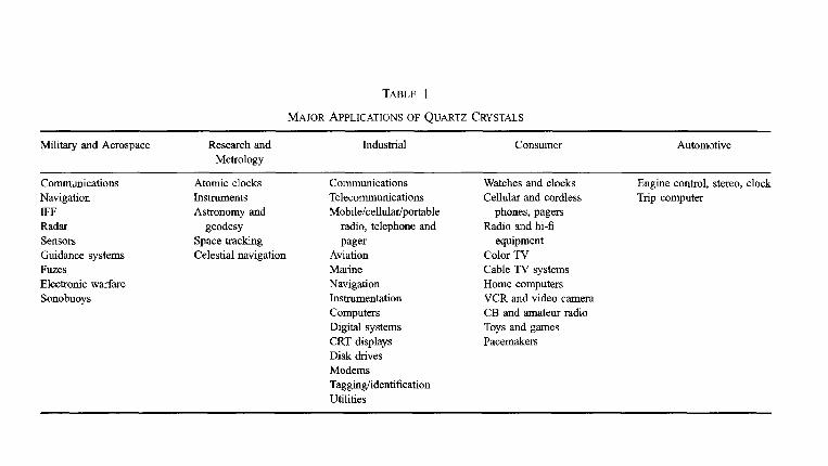
TABLE 1
MAJOR APPLICATIONS OF QUARTZ CRYSTALS
Military and Aerospace Research and Metrology
Industrial Consumer Automotive
Communications Navigation IFF Radar Sensors Guidance systems Fuzes Electronic warfare Sonobuoys
Atomic clocks Instruments Astronomy and
geodesy Space tracking Celestial navigation
Communications Telecommunications Mobile/cellular/portable
radio, telephone and
Pager Aviation Marine Navigation Instrumentation Computers Digital systems CRT displays Disk drives Modems Tagging/identification Utilities
Watches and clocks Cellular and cordless
phones, pagers Radio and hi-fi
equipment Color TV Cable TV systems Home computers VCR and video camera CB and amateur radio Toys and games Pacemakers
Engine control, stereo, clock Trip computer
640 John R. Vig and Arthur Ballato
which spread-spectrum techniques are used for maximizing the number of simultaneous users in the assigned frequency band.
In the United States, the genesis of the quartz crystal industry can be traced to the decision in 1939 to make large-scale use of crystal control in military communication systems [l]. In early military systems, controlling the carrier frequency of radio communications systems was the primary application. The typical (normalized frequency) accuracy in World War II systems was 200 ppm [2]. In systems of the 1960s and 197Os, the typical accuracy requirements ranged from 40 to 0.5 ppm [3]. In systems that are currently in production or development, the accuracy requirements range from 5 ppm in some tactical radios to parts in 1012 in some navigation, electronic warfare, and strategic communication systems. In addition to possessing high accu- racy, the frequency sources of modern systems must also exhibit low noise characteristics and must remain stable in extreme environments.
In the following section, the most demanding applications are reviewed. Many of these are military applications; some of these have parallels in the civilian world.
In early military systems, controlling the carrier frequency for improved spectrum utilization was the principal driver of frequency control technology. In modern systems, the major drivers are spread-spectrum systems that require ever-higher clock accuracies, surveillance systems that require low- noise oscillators in the presence of platform vibrations, and tactical (hand- held) systems that require ever-higher accuracies with the lowest possible battery consumption and in the smallest possible volume.
A. COMMUNICATION SYSTEMS
In communication systems, the accuracy and stability of oscillators and clocks affect important system performance parameters, such as the spectrum utilization, resistance to unintentional and intentional (i.e., jamming) inter- ference, signal acquisition speed autonomy period, and bit error rates.
1. Spectrum Utilization
In the field of communications electronics, the subject of frequency control is intimately related to the subject of frequency spectrum utilization [4]. Historically, in both commercial and military systems, to allow for more users in a given frequency band it was necessary to reduce the channel spacings, which required the tightening of the frequency tolerances allowed in
7 Frequency Control Devices 641
both the transmitters and receivers. As the number of users grew, and as technology allowed the allocation of higher frequency bands, the frequency tolerances became tighter and tighter. The same channel spacing at a higher frequency, of course, requires tighter frequency tolerance. The frequency accuracy requirements of tactical radios prior to the advent of spread- spectrum techniques were typically 10 to 50ppm. Radios that employ spread-spectrum techniques typically require 5- to O.OOl-ppm oscillators. In digital communication systems, not only must the oscillators possess high accuracy, they must also have low noise characteristics, for reasons that are discussed below.
The noise of oscillators can also limit the capacity of communication systems. Since the noise from a transmitter in one channel extends to neighboring channels, as the number of transmitters grows, the noise accumulates to the point where receivers can no longer function properly. For example, in one L-band satellite communication system, the vibration- induced phase noise [5, 61 is a serious limitation on the number of users per transponder when the users are on vibrating platforms, such as aircraft, trucks, etc. The noise from a typical commercial oscillator (2 x lo-‘perg vibration sensitivity) limits the number of users to less than 100 per transponder, whereas a state-of-the-art oscillator (2 x lo-“perg vibration sensitivity) can allow as many as 1200 users per transponder. Since the rental of a transponder costs more than $1 million per year, the economic impact of oscillator noise can be significant [7].
2. Resistance to Jamming
Spread-spectrum techniques are used in military systems primarily for rejecting intentional and unintentional jamming, and for communication security [8, 91. In spread-spectrum systems, the transmitters and receivers contain clocks that must be synchronized. For example, frequency hopping is a spread-spectrum technique used in several evolving military communication systems. In such systems, the transmitters and receivers must hop to the same frequency at the same time. The faster the hopping rate, the higher the jamming resistance, and the more accurate the clocks must be. For example, for a system with a hopping rate of 1000 hops per second, the dwell time at each frequency is 1 millisecond. For such a system to operate properly, the clocks must remain synchronized to about 100 microseconds.
When several radio nets operate in an area, self-jamming can be a problem if the nets operate independently of one another, i.e., if the nets are not
642 John R. Vig and Arthur Ballato
orthogonal. Radios of neighboring nets can then occasionally hop to the same frequency at the same time, thus producing self-jamming. When the nets are orthogonal, i.e., when the neighboring nets are synchronized and use codes that ensure that radios do not hop to the same frequency at the same time, the radios must not only be synchronized within a net but also to those of neighboring nets. This requires an even higher clock accuracy.
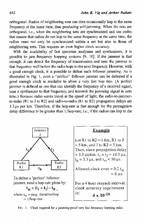
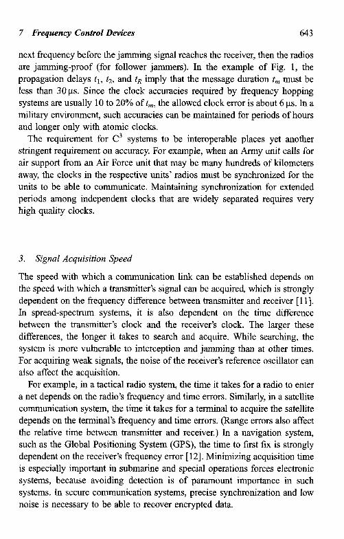
With the availability of fast spectrum analyzers and synthesizers, it is possible to jam frequency hopping systems [9, lo]. If the jammer is fast enough, it can detect the frequency of transmission and tune the jammer to that frequency well before the radio hops to the next frequency. However, with a good enough clock, it is possible to defeat such follower jamming. As is illustrated in Fig. 1, even a “perfect” follower jammer can be defeated if a good enough clock is available to allow a very fast hop rate. (A perfect jammer is defined as one that can identify the frequency of a received signal, tune a synthesizer to that frequency, and transmit the jamming signal in zero time.) Because radio waves travel at the speed of light, the radio-to-jammer- to-radio (Rl to J to R2) and radio-to-radio (Rl to R2) propagation delays are 3.3 us per km. Therefore, if the hop-rate is fast enough for the propagation delay difference to be greater than 1 /hop-rate, i.e., if the radios can hop to the
Jammer J
Radio RI
Radio R2
To defeat a “perfect” follower jammer, need a hop-rate given by:
&j < @I + f2) - t, , where t, = msg. duration/hop
= l/hop-rate
ExamDIe
Let Rl to R2 = 1 km, Rl to J = 5 km, and J to R2 = 5 km. Then, since propagation delay = 3.3 us/km, t, = t2 = 16.5 us, tR = 3.3 ps, and t, < 30 ps.
Allowed clock error = 0.2 t, = 6 /.ts.
For a 4 hour resynch interval, clock accuracy requirement is:
4 x 10.10
FIG. 1. Ciock required for a jamming-proof very fast frequency hopping radio.
7 Frequency Control Devices 643
next frequency before the jamming signal reaches the receiver, then the radios are jamming-proof (for follower jammers). In the example of Fig. 1, the propagation delays tr, t2, and tR imply that the message duration tm must be less than 30~s. Since the clock accuracies required by frequency hopping systems are usually 10 to 20% of tm, the allowed clock error is about 6 us. In a military environment, such accuracies can be maintained for periods of hours and longer only with atomic clocks.
The requirement for C3 systems to be interoperable places yet another stringent requirement on accuracy. For example, when an Army unit calls for air support from an Air Force unit that may be many hundreds of kilometers away, the clocks in the respective units’ radios must be synchronized for the units to be able to communicate. Maintaining synchronization for extended periods among independent clocks that are widely separated requires very high quality clocks.
3. Signal Acquisition Speed
The speed with which a communication link can be established depends on the speed with which a transmitter’s signal can be acquired, which is strongly dependent on the frequency difference between transmitter and receiver [ 111. In spread-spectrum systems, it is also dependent on the time difference between the transmitter’s clock and the receiver’s clock. The larger these differences, the longer it takes to search and acquire. While searching, the system is more vulnerable to interception and jamming than at other times. For acquiring weak signals, the noise of the receiver’s reference oscillator can also affect the acquisition.
For example, in a tactical radio system, the time it takes for a radio to enter a net depends on the radio’s frequency and time errors. Similarly, in a satellite communication system, the time it takes for a terminal to acquire the satellite depends on the terminal’s frequency and time errors. (Range errors also affect the relative time between transmitter and receiver.) In a navigation system, such as the Global Positioning System (GPS), the time to first fix is strongly dependent on the receiver’s frequency error [ 121. Minimizing acquisition time is especially important in submarine and special operations forces electronic systems, because avoiding detection is of paramount importance in such systems. In secure communication systems, precise synchronization and low noise is necessary to be able to recover encrypted data.
644 John R. Vig and Arthur Ballato
4. Autonomy Period
Autonomy period also called “radio silence interval,” is important in modem warfare. For example, to remain undetected submarine and special operations forces must, at times, refrain from communicating over the air for extended periods. When clocks are not resynchronized and resyntonized (i.e., re- frequency calibrated), time and frequency errors increase with increasing mission duration. The better the long-term stability of the systems’ oscillators, the longer can be the allowable autonomy period and the shorter will be the subsequent acquisition time.
5. Digital Communications
Digital communication systems, whether commercial or military, must be synchronized and have the same data rates. Synchronization plays a critical role in such systems because it ensures that information transfer is performed with minimal buffer overflow or underflow events, i.e., with an acceptable level of “slips.” Slips cause problems, e.g., missing lines in FAX transmis- sion, clicks in voice transmission, loss of encryption key in secure voice transmission, and data retransmission [ 13, 141.
The phase noise of oscillators can lead to erroneous detection of phase transitions, i.e., to bit errors, when phase-shift-keyed (PSK) digital modula- tion is used. In digital communications, for example, where 8-ary PSK is used, the maximum phase tolerance is f22.5”, of which f7.5” is the typical allowable carrier noise contribution [ 141. Due to the statistical nature of phase deviations, if the RMS phase deviation is 1.5”, for example, the probability of exceeding the f7.5” phase deviation is 6 x 10⁻⁷, which can result in a bit error rate that is significant in some applications.
Shock and vibration can produce large phase deviations even in “low- noise” oscillators [5, 61. Moreover, when the frequency of an oscillator is multiplied by N, the phase deviations are also multiplied by N For example, a phase deviation of 1 OV3 radian at 10 MHz becomes 1 radian at 10 GHz. Such large phase excursions can be catastrophic to the performance of systems, e.g., those that rely on phase locked loops (PLL) or phase sift keying. Low- noise, acceleration-insensitive oscillators are essential in such applications.
B. NAVIGATION
Precise time is essential to precise navigation. Historically, navigation has been a principal motivator in man’s search for better clocks. Even in ancient
7 Frequency Control Devices 645
times, one could measure latitude by observing the stars’ positions, but determining longitude is a problem of timing. Since the earth makes one revolution in 24 hours, one can determine longitude from the time difference, At, between local time (which was determined from the sun’s position) and the time at the Greenwich meridian (which was determined by a clock): longitude in degrees = (360”/24 hours) x At in hours.
Today’s military (and civilian) navigation systems require ever-greater accuracies. Modern navigation systems utilize ultraprecise clocks and radio transmissions of precisely timed navigation signals. The Global Positioning System (GPS), developed by the U.S. Department of Defense, is the most accurate worldwide navigation system available. As the price of GPS receivers has declined, the number of civilian applications of GPS has increased. Today, the number of GPS receivers sold for civilian applications far exceeds the military sales.
In GPS, navigation is accomplished by one-way time measurements [15-181. Since electromagnetic waves travel 0.3 meters (i.e., a foot) per nanosecond,, if, for example, a vessel’s timing was in error by a microsecond, a navigational error of 300 meters would result. In GPS, atomic clocks in the satellites and quartz oscillators in the receivers provide nanosecond-level accuracies. The resulting (worldwide) navigational accuracies are about 10 meters and differential accuracies can be as good as a few millimeters.
Each GPS spacecraft contains four high-performance atomic clocks. (Only one is turned on; the others are for backup.) The military GPS receivers contain oven-controlled crystal oscillators (OCXO); the less expensive commercial receivers contain less expensive temperature-compensated crystal oscillators (TCXO). The spacecraft clocks provide a time accuracy of better than 100 nanoseconds [ 17, 181. The oscillator is a key component in the receiver [ 121. In military receivers, especially, the oscillator’s performance has a direct influence on system performance. The noise of the oscillator affects the navigation accuracy and the performance (i.e., jamming margin) in a high- jamming environment; the medium-term (10 to 1000 second) stability affects the reacquisition capability, system integrity monitoring, and performance in a high-jamming environment; the long-term stability affects the time to subse- quent fix and the capability to operate with less than four satellites; the warm- up time of the oscillator affects the time to first fix; and the power requirement and the size of the oscillator affect the receiver’s battery life, mission duration, and weight.
646 John R Vig and Arthur Ballato
c. f&RVEJLLANCE
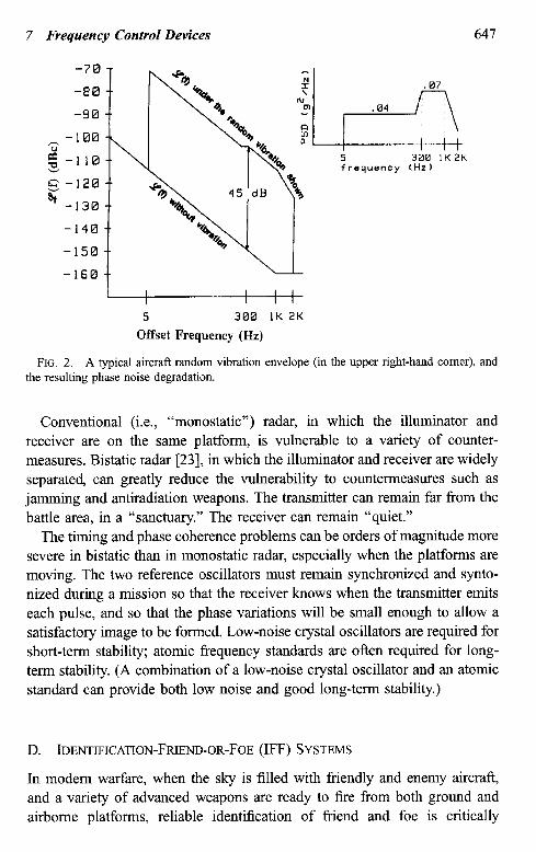
In surveillance, Doppler radars especially require low-noise oscillators [ 19, 201. The velocity of the target and the radar frequency are primary determi- nants of the phase noise requirements. Slow-moving targets produce small Doppler shifts, therefore, low phase noise close to the carrier is required. To detect fast-moving targets, low noise far fi-om the carrier is required. For example, when using an X-band radar to detect a 4kmjhour target (e.g., a slowly moving vehicle), the noise 70 Hz Corn the carrier is the important parameter, whereas to detect supersonic aircraft, the noise beyond 10 kHz is important.
When a radar is on a stationary platform, the phase noise requirements can usually be met with commercially available oscillators. A good quartz crystal @ulk acoustic wave, BAW) oscillator can provide sufficiently low noise close to the carrier, and a good surface acoustic wave (SAW) oscillator can provide sufficiently low noise far from the carrier [21]. Very far from the carrier, dielectric resonator oscillators (DRO) can provide lower noise than either BAW or SAW oscillators. A combination of oscillators can be used to achieve good performance in multiple spectral regions [22], e.g., a DRO phase locked to a frequency-multiplied BAW oscillator can provide low noise both close to the carrier and far from the carrier.
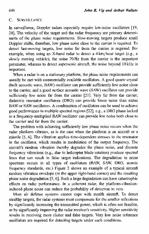
The problem with achieving sufficiently low phase noise occurs when the radar platform vibrates, as is the case when the platform is an aircraft or a missile [5, 61. The vibration applies time-dependent stresses to the resonator in the oscillator, which results in modulation of the output frequency. The aircraft’s random vibration thereby degrades the phase noise, and discrete frequency vibrations (e.g., due to helicopter blade rotation) produce spectral lines that can result in false target indications. The degradation in noise spectrum occurs in all types of oscillators (BAW, SAW, DRO, atomic frequency standards, etc.) Figure 2 shows an example of a typical aircraft random vibration envelope (in the upper right-hand comer) and the resulting phase noise degradation [5,6]. Such a large degradation can have catastrophic effects on radar performance. In a coherent radar, the platform-vibration- induced phase noise can reduce the probability of detection to zero.
Most air defense systems cannot cope with stealth aircraft. To detect stealthy targets, the radar systems must compensate for the smaller reflections by significantly increasing the transmitted power, which is often not feasible, or by significantly improving the radar receiver’s sensitivity. Higher sensitivity results in receiving more clutter and false targets. Very low noise reference oscillators are required for detecting targets under such conditions.
7 Frequency Control Devices 647
-70
-88
-90
-100
g-110
E: s
-120
-130
-140
-150
-160
I I I I
5 300 IK 2K
Offset Frequency (Hz)
FIG. 2. A typical aircraft random vibration envelope (in the upper right-hand comer), and the resulting phase noise degradation.
Conventional (i.e., “monostatic”) radar, in which the illuminator and receiver are on the same platform, is vulnerable to a variety of counter- measures. Bistatic radar [23], in which the illuminator and receiver are widely separated, can greatly reduce the vulnerability to countermeasures such as jamming and antiradiation weapons. The transmitter can remain far from the battle area, in a “sanctuary.” The receiver can remain “quiet.”
The timing and phase coherence problems can be orders of magnitude more severe in bistatic than in monostatic radar, especially when the platforms are moving. The two reference oscillators must remain synchronized and synto- nized during a mission so that the receiver knows when the transmitter emits each pulse, and so that the phase variations will be small enough to allow a satisfactory image to be formed. Low-noise crystal oscillators are required for short-term stability; atomic frequency standards are often required for long- term stability. (A combination of a low-noise crystal oscillator and an atomic standard can provide both low noise and good long-term stability.)
D. IDENTIFICATION-FRIEND-• R-FOE (IFF) SYSTEMS
In modern warfare, when the sky is filled with friendly and enemy aircraft, and a variety of advanced weapons are ready to fire from both ground and airborne platforms, reliable identification of friend and foe is critically
648 John R. Vig and Arthur Ballato
important. Friendly-fire casualties due to lack of adequate IFF systems have been a major problem in recent wars [24]. Precise timing can play a major role in solving this problem. For example, cooperative IFF systems use an interrogation/response method that employs cryptographically encoded spread-spectrum signals. The interrogation signal received by a friend is supposed to result in the “correct” code being automatically sent back via a transponder on the friendly platform. The “correct” code must be changed frequently to prevent a foe from recording and transmitting that code (“repeat jamming”), thereby appearing to be a friend. The code is changed at the end of what is called the code validity interval, (CV).
The better the clock accuracy, the shorter can be the CVI, the more resistant the system can be to repeat jamming, and the longer can be the autonomy period for users who cannot resynchronize their clocks during a mission. The CVI chosen is usually dictated by the accuracies achievable with low-power oscillators.
E. ELECTRONIC WARFARE
The ability to locate radio emitters is important in modern warfare. One method of locating emitters is to measure the time difference of arrival of the same signal at widely separated locations. Emitter location by means of this method depends on the availability of highly accurate clocks, and on highly accurate methods of synchronizing clocks that are widely separated. Since electromagnetic waves travel at the speed of light (30 cm per nanosecond), the clocks of emitter-locating systems must be kept synchronized to within nanoseconds to locate emitters with high accuracy. (Multipath and the geometrical arrangement of emitter locators usually result in a dilution of precision.) Without resynchronization, even the best available militarized atomic clocks can maintain such accuracies for periods of only a few hours. With the availability of GPS and using the “GPS common view” method of time transfer, widely separated clocks can be synchronized to better than 10 ns [ 171. An even more accurate method of synchronization is “two-way time transfer via communication satellites,” which, by means of very small aperture terminals (VSATs) and pseudonoise modems, can attain subnanose- cond time transfer accuracies [25].
An important application for frequency sources is the ELINT (ELectronic INTelligence) receiver. These receivers are used to search a broad range of frequencies for signals that may be emitted by a potential adversary. The frequency source must be as noise-free as possible so as not to obscure weak
7 Frequency Control Devices 649
incoming signals. The frequency source must also be extremely stable and accurate to allow accurate measurement of the incoming signal’s character- istics.
F. MISSILE GUIDANCE
When a missile is guided by ground radar, the radar is vulnerable to antiradiation missiles and other countermeasures. Placing the radar on- board the missile can greatly reduce the vulnerability, but at the expense of placing much greater demands on missile components, especially the refer- ence oscillator. As previously discussed, the missile’s high vibration levels degrade the oscillator phase noise by a wide margin, Vibration-insensitive low-noise oscillators are required for on-board radar systems. Such systems could benefit greatly from improvements in vibration-resistant low-noise oscillators [5].
G. BATTERY CONSUMFTION
Tactical military electronic systems are usually powered by batteries. In many of these systems, precise timing plays an essential role. When the system is not being used, everything except the clock can usually be turned off. As a result, the power requirement of the clock is a major determinant of battery consumption. For example, to power the time and frequency unit in one tactical satellite terminal during the required lo-day standby period a battery pack weighing 18 kg was required. By replacing the power-hungry, oven- controlled crystal oscillator of the original design with a Microcomputer Compensated Crystal Oscillator (MCXO) [26], which is a much lower power oscillator of similar accuracy, 12 kg of battery weight could be saved.
The cost savings resulting from reducing the power requirements of oscillators can be large. For example, a calculation estimates that for one model of tactical radio, the cost savings resulting from reducing the power requirement for the radio’s 20-year life, (assuming peace-time usage of 2 hours per day) is $48,000 per milliwatt per 10,000 radios [27]. Since more than 200,000 of these radios may eventually be produced, the eventual cost savings when this radio is fully fielded may be mom than $1 million per mW of power saving! During a conflict, the radios would of course, be used 24 hours per day, for an even greater saving; however, the real benefit of lower power radios is a lighter, more mobile force, which can operate for longer periods without needing battery replenishment.
650 John R Vig and Arthur Ballato
Another reason for minimizing the power dissipation of oscillators is that the dissipation often produces undesirably large infrared signatures, which makes the system easier to detect by an adversary.
H. SURVIVABILITY UNDER RADIATION AND HIGH ACCELERATION
Survivability under ionizing radiation and high shock and vibration condi- tions is primarily a military (and space) requirement. Gun-hardened oscilla- tors are required for example, for smart munitions, air-dropped and artillery- emplaced sensors, mzes, and space defense systems. The highly shock- resistant oscillators have been developed that can withstand the shock of being launched from a howitzer [28, 291. Radiation-hardening of oscillators used to be a major issue in many military systems because a high-intensity pulse of nuclear radiation stops clocks and causes large temporary, and smaller permanent, frequency offsets in frequency standards [30]. With the threat of nuclear war receding, radiation-hardening is less of an issue today for military systems (although it remains an important issue for space systems).
I. LOGISTICS COSTS
The long-term stability and the lifetime of oscillators often have a significant impact on logistics costs. As the oscillator’s frequency ages (and all but cesium beam frequency standards do age), or as, e.g., a cesium beam frequency standard nears end of life, at some point, the oscillators must be recalibrated or replaced. A need for frequent recalibration or replacement has a significant adverse impact on the life cycle cost of equipment. Lower aging oscillators do cost more initially; however, the increased cost is often recovered rapidly through a decrease in logistics costs. An important goal of research aimed at reducing oscillator aging is to provide systems with calibration-free life.
III. Frequency Control Device Fundamentals
The fundamentals of quartz oscillators are reviewed in this section, with emphasis on quartz frequency standards (as opposed to inexpensive clock oscillators). The subjects discussed include: crystal resonators and oscillators, oscillator types, and the characteristics and limitations of temperature- compensated crystal oscillators (TCXO) and oven-controlled crystal oscilla-
7 Frequency Control Devices 651
tors (OCXO). The oscillator instabilities discussed include: aging, noise, frequency vs temperature, warm-up, acceleration effects, magnetic-field effects, radiation effects, and atmospheric pressure effects. Interactions among the various effects are also considered. Guidelines are provided for oscillator comparison and selection. Discussions of specifications are also included as are references and suggestions for further reading.
A. CRYSTAL OSCILLATORS
I. Oscillator Basics
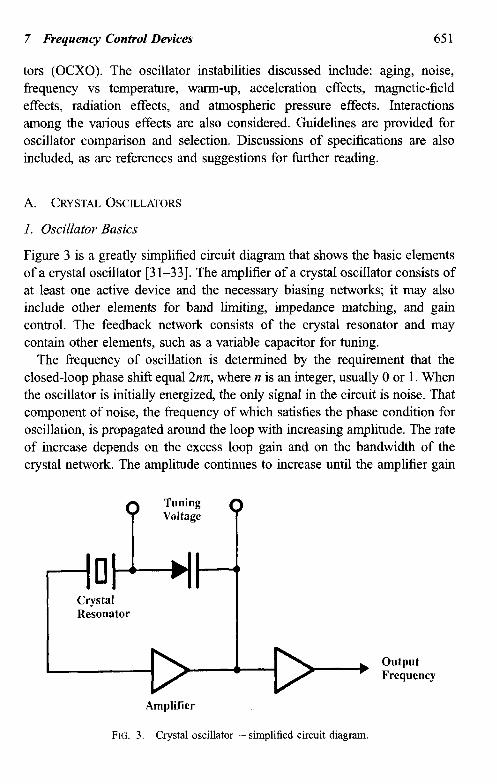
Figure 3 is a greatly simplified circuit diagram that shows the basic elements of a crystal oscillator [3 l-331. The amplifier of a crystal oscillator consists of at least one active device and the necessary biasing networks; it may also include other elements for band limiting, impedance matching, and gain control. The feedback network consists of the crystal resonator and may contain other elements, such as a variable capacitor for tuning.
The frequency of oscillation is determined by the requirement that the closed-loop phase shift equal 2nrr, where n is an integer, usually 0 or 1. When the oscillator is initially energized, the only signal in the circuit is noise. That component of noise, the frequency of which satisfies the phase condition for oscillation, is propagated around the loop with increasing amplitude. The rate of increase depends on the excess loop gain and on the bandwidth of the crystal network. The amplitude continues to increase until the amplifier gain
Amplifier
FIG. 3. Crystal oscillator - simplified circuit diagram.
652 John R. Vig and Arthur Ballato
is reduced, either by the nonlinearities of the active elements (in which case it is self-limiting) or by an external level-control method.
At steady state, the closed-loop gain is 1. If a phase perturbation A@ occurs, the frequency of oscillator must shift by a Af to maintain the 2~7 phase condition. It can be shown that for a series-resonance oscillator
where QL is the loaded Q of the crystal in the network [3 11. (“Crystal” and “resonator” are often used interchangeably with “crystal unit,” although “crystal unit” is the official name. See references 3 to 6 for further information about crystal units.) Crystal oscillator design information can be found in references 31, 32, 35, and 36. The abbreviation for crystal oscillator is X0.
2. Crystal Unit Equivalent Circuit
A quartz crystal unit is a quartz wafer to which electrodes have been applied, and which is hermetically sealed in a holder structure. (The wafer is often referred to as the “blank,” or the “crystal plate.“) Although the design and fabrication of crystal units comprise a complex subject, the oscillator designer can treat the crystal unit as a circuit component and just deal with the crystal unit’s equivalent circuit.
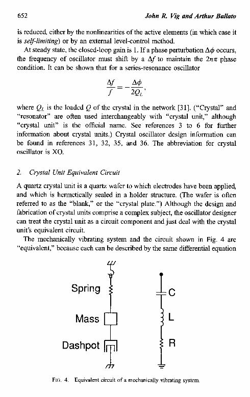
The mechanically vibrating system and the circuit shown in Fig. 4 are “equivalent,” because each can be described by the same differential equation
Spring
? Mass
Dashpot
FIG. 4. Equivalent circuit of a mechanically vibrating system.
7 Frequency Control Devices 653
[37]. The mass, spring, and damping element (i.e., the dashpot) correspond to the inductor, capacitor, and resistor. The driving force corresponds to the voltage, the displacement of the mass to the charge on the capacitor, and the velocity to the current.
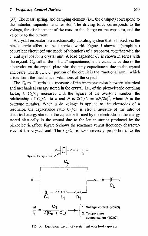
A crystal resonator is a mechanically vibrating system that is linked via the piezoelectric effect, to the electrical world. Figure 5 shows a (simplified) equivalent circuit (of one mode of vibration) of a resonator, together with the circuit symbol for a crystal unit. A load capacitor CL is shown in series with the crystal. CO, called the “shunt” capacitance, is the capacitance due to the electrodes on the crystal plate plus the stray capacitances due to the crystal enclosure. The RI, Lr, Cr portion of the circuit is the “motional arm,” which arises from the mechanical vibrations of the crystal.
The CO to C1 ratio is a measure of the interconversion between electrical and mechanical energy stored in the crystal, i.e., of the piezoelectric coupling factor, k. CO/C1 increases with the square of the overtone number; the relationship of CO/C1 to k and N is 2CO/C1 = [dV/2k12, where N is the overtone number. When a dc voltage is applied to the electrodes of a resonator, the capacitance ratio CO/C, is also a measure of the ratio of electrical energy stored in the capacitor formed by the electrodes to the energy stored elastically in the crystal due to the lattice strains produced by the piezoelectric effect. Figure 6 shows the reactance versus frequency character- istic of the crystal unit. The CO/C1 is also inversely proportional to the
---+-k- CL
Af Cl - = 2(C, + CL) -
1. Voltage control (VCXO)
f S 2. Temperature compensation (TCXO)
FIG. 5. Equivalent circuit of crystal unit with load capacitor.
654 John R. Vig and Arthur Ballato
/ Antiresonance
Area of Usual
Frequency
1
27EfCo
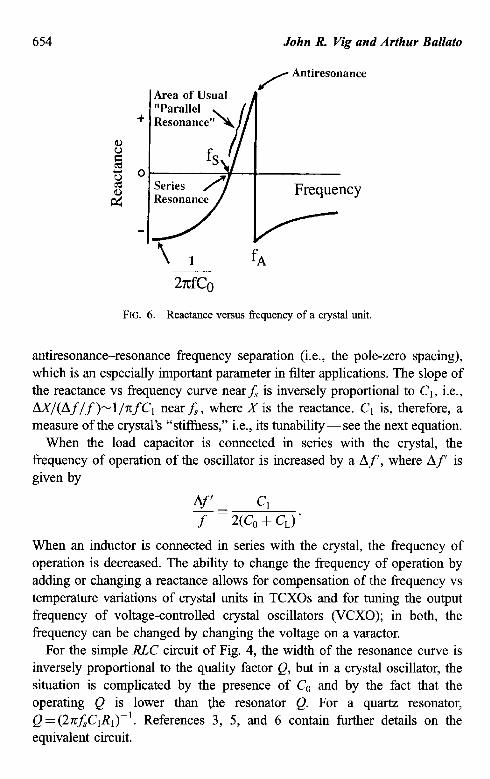
FIG. 6. Reactance versus frequency of a crystal unit.
antiresonance-resonance frequency separation (i.e., the pole-zero spacing), which is an especially important parameter in filter applications. The slope of the reactance vs frequency curve nearfs is inversely proportional to Cl, i.e., A-WAf/f>-l/-nfC I near fS, where X is the reactance. C1 is, therefore, a measure of the crystal’s “stifiess,” i.e., its tunability- see the next equation.
When the load capacitor is connected in series with the crystal, the frequency of operation of the oscillator is increased by a Af’, where Af’ is given by
A.’ Cl
- = 2(C, + C,) * f
When an inductor is connected in series with the crystal, the frequency of operation is decreased. The ability to change the frequency of operation by adding or changing a reactance allows for compensation of the frequency vs temperature variations of crystal units in TCXOs and for tuning the output frequency of voltage-controlled crystal oscillators (VCXO); in both, the frequency can be changed by changing the voltage on a varactor.
For the simple RLC circuit of Fig. 4, the width of the resonance curve is inversely proportional to the quality factor Q, but in a crystal oscillator, the situation is complicated by the presence of C, and by the fact that the operating Q is lower than the resonator Q. For a quartz resonator, Q=(2n~CIRI)-‘. References 3, 5, and 6 contain further details on the equivalent circuit.
7 Frequency Control Devices 655
Some of the numerous advantages of a quartz crystal resonator over a tank circuit built from discrete Rs, Cs, and Ls are that the crystal is far stiffer and has a far higher Q than what could be built from normal discrete components. For example, a ~-MHZ fundamental mode AT-cut crystal may have Ci = 0.01 pF, Lr = 0.1 H, RI = 5 R, and Q = 106. A O.Ol-pF capacitor is not available, since the leads attached to such a capacitor would alone probably contribute more than 0.0 1 pF. Similarly, a 0.1 -H inductor would be physically large, would need to include a large number of turns, and would need to be superconducting to have a resistance ~5 Sz.
3. Stability versus Tunability
In most crystal oscillator types, a variable-load capacitor is used to adjust the frequency of oscillation to the desired value. Such oscillators operate at the parallel resonance region of Fig. 5, where the reactance vs frequency slope (i.e., the “stiffness”) is inversely proportional to Cl. For maximum frequency stability with respect to reactance (or phase) perturbations in the oscillator circuit, the reactance slope (or phase slope) must be maximum. This requires that the Cr be minimum. The smaller the C,, however, the more difficult it is to tune the oscillator (i.e., the smaller is Af’ for a given change in CL). The highest stability oscillators use crystal units that have a small C1 (and a high Q). Since C1 decreases rapidly with overtone number, high-stability oscilla- tors generally use third- or fifth-overtone crystal units. Overtones higher than fifth are rarely used, because RI also increases rapidly with overtone number, and some tunability is usually desirable to allow setting the oscillator to the desired frequency.
Wide-tuning-range VCXOs use fundamental mode crystal units of large Cl. Voltage control is used for the following purposes: to frequency or phase lock two oscillators; for frequency modulation; for compensation, as in a TCXO (see below); and for calibration (i.e., for adjusting the frequency to compen- sate for aging). Whereas a high-stability, ovenized lo-MHz VCXO may have a frequency adjustment range of f5 x 1O-7 and an aging rate of 2 x lo-* per year, a wide-tuning-range lo-MHz VCXO may have a tuning range of f50 parts per million @pm) and an aging rate of 2 ppm per year.
In general, making an oscillator tunable over a wide frequency range degrades its stability because making an oscillator susceptible to intentional tuning also makes it susceptible to factors that result in unintentional tuning. For example, if an oven-controlled crystal oscillator (OCXO) is designed to have a stability of 1 x lo-l2 for a particular averaging time and a tunability of
656 John R. Vig and Arthur Ballato
1 x 10e7, then the crystal’s load reactance must be stable to 1 x 10P5 for that averaging time. Achieving such load-reactance stability is difficult because the load-reactance is affected by stray capacitances and inductances, by the stability of the varactor’s capacitance vs voltage characteristic, and by the stability of the voltage on the varactor. Moreover, the 1 x lop5 load-reactance stability must be maintained not only under benign conditions, but also under changing environmental conditions (temperature, vibration, radiation, etc.). Therefore, the wider the tuning range of an oscillator, the more difficult it is to maintain a high stability.
4. Quartz and the Quartz Crystal Unit
A quartz crystal unit’s high Q and high stiffness (small C,) make it the primary frequency- and frequency-stability-determining element in a crystal oscillator. The Q values of crystal units are much higher than those attainable with other circuit elements. In general purpose crystal units, Qs are generally in the range of lo4 to 106. A high-stability ~-MHZ crystal unit’s Q is typically in the range of two to three million. The intrinsic Q, limited by internal losses in the crystal, has been determined experimentally to be inversely propor- tional to frequency (i.e., the Qf product is a constant for a given resonator type). For AT- and SC-cut resonators, the maximum Qf= 16 million whenfis in MHz.
Quartz (which is a single-crystal form of SiO*) has been the material of choice for stable resonators since shortly after piezoelectric crystals were fn-st used in oscillators-in 1918. Although many other materials have been explored, none has been found to be better than quartz. Quartz is the only material known that possesses the following combination of properties:
1. It is piezoelectric (“pressure electric”; piezein means “to press” in Greek).
2. Zero temperature coefficient resonators can be made when the plates are cut along the proper directions with respect to the crystallographic axes of quartz.
3. Of the zero temperature coefficient cuts, one, the SC-cut (see below), is “stress compensated.”
4. It has low intrinsic losses (i.e., quartz resonators can have high Qs). 5. It is easy to process because it is hard but not brittle, and, under normal
conditions, it has low solubility in everything except the fluoride etchants.
7 Frequency Control Devices 657
6. It is abundant in nature. 7. It is easy to grow in large quantities, at low cost, and with relatively high
purity and perfection.
The direct piezoelectric effect was discovered by the Curie brothers in 1880. They showed that when a weight was placed on a quartz crystal, charges appeared on the crystal surface; the magnitude of the charge was proportional to the weight. In 1881, the converse piezoelectric effect was illustrated; when a voltage was applied to the crystal, the crystal deformed due to the lattice strains caused by the effect. The strains reversed when the voltage was reversed.
Of the 32 crystal classes, 20 exhibit the piezoelectric effect (but only a few of these are useful). Piezoelectric crystals lack a center of symmetry. When a force deforms the lattice, the centers of gravity of the positive and negative charges in the crystal can be separated so as to produce surface charges. The piezoelectric effect can provide a coupling between an electrical circuit and the mechanical properties of a crystal. Under the proper condi- tions, a “good” piezoelectric resonator can stabilize the frequency of an oscillator circuit.
Quartz crystals are highly anisotropic, that is, the properties vary greatly with crystallographic direction. For example, when a quartz sphere is etched in hydrofluoric acid the etching rate is more than 100 times faster along the fastest etching rate direction, the 2 direction, than along the slowest direction, the slow-X direction. The constants of quartz, such as the thermal expansion coefficient and the temperature coefficients of the elastic constants, also vary with direction. That crystal units can have zero temperature coefficients of frequency is a consequence of the temperature coefficients of the elastic constants ranging from negative to positive values.
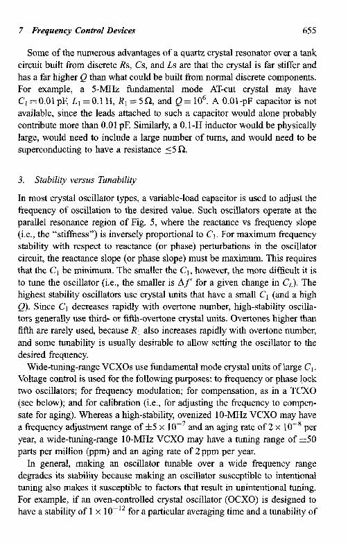
The locus of zero-temperature-coefficient cuts in quartz is shown in Fig. 7. The X, I: and 2 directions have been chosen to make the description of properties as simple as possible. The Z-axis in Fig. 5 is an axis of threefold symmetry in quartz; in other words, the physical properties repeat every 120” as the crystal is rotated about the Z-axis. The cuts usually have two-letter names, where the “T” in the name indicates a temperature-compensated cut; for instance, the AT-cut was the first temperature-compensated cut discovered. The FC-, IT-, BT-, and RT-cuts are other cuts along the zero-temperature- coefficient locus. These cuts were studied in the past (before the discovery of the SC-cut) for some special properties, but are rarely used today. The highest-stability crystal oscillators employ SC-cut or AT-cut crystal units.
658 John R. Vig and Arthur Ballato
9o” I 1 I 1 I
60e AT FC IT 30. L SC
6 o- l LC
The AT, FC. fT. SC. BT. and RTcuts are on me kxi of zero temperature coefficienf cuts. the LC is a Wwar wdficienf’ wf mat is used in a fhennomefer.
Y-Cut: = +90 ppmpc (thickness-shear mode)
X-Cut: ” -20 ppmm (extensional mode)
FIG. 7. Zero-temperature-coefficient cuts of quartz.
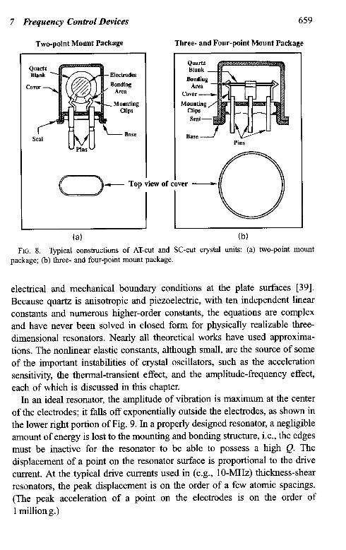
Because the properties of a quartz crystal unit depend strongly on the angles of cut of the crystal plate, in the manufacture of crystal units the plates are cut from a quartz bar along precisely controlled directions with respect to the crystallographic axes. The orientations of the plates are checked by means of x-ray diffraction. In some applications, the orientations must be controlled with accuracies of a few seconds of angle. After shaping to required dimensions, metal electrodes are applied to the wafer. Circular plates with circular electrodes are the most commonly used geometries, although the blanks and electrodes may also be of other geometries. The electroded wafer is mounted in a holder structure [38]. Figure 8 shows the two common types of holder structures used for resonators with frequencies greater than 1 MHz. (The 32-kHz tuning fork resonators used in quartz watches are packaged typically in small tubular enclosures.)
Because quartz is piezoelectric, a voltage applied to the electrodes causes the quartz plate to deform slightly. The amount of deformation due to an alternating voltage depends on how close the frequency of the applied voltage is to a natural mechanical resonance of the crystal. To describe the behavior of a resonator, the differential equations for Newton’s laws of motion for a continuum, and for Maxwell’s equations, must be solved with the proper
7 Frequency Control Devices
Two-point Mount Package
659
Three- and Four-point Mount Package
Cover -
f SCd
c--J-- Top view Of
la)
Seal -
Base f Pins
cover -
: 0
(b)
FIG. 8. Typical constructions of AT-cut and SC-cut crystal units: (a) two-point mount package; (b) three- and four-point mount package.
electrical and mechanical boundary conditions at the plate surfaces [39]. Because quartz is anisotropic and piezoelectric, with ten independent linear constants and numerous higher-order constants, the equations are complex and have never been solved in closed form for physically realizable three- dimensional resonators. Nearly all theoretical works have used approxima- tions. The nonlinear elastic constants, although small, are the source of some of the important instabilities of crystal oscillators, such as the acceleration sensitivity, the thermal-transient effect, and the amplitude-frequency effect, each of which is discussed in this chapter.
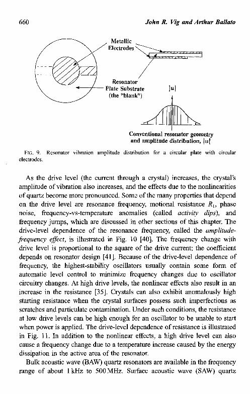
In an ideal resonator, the amplitude of vibration is maximum at the center of the electrodes; it falls off exponentially outside the electrodes, as shown in the lower right portion of Fig. 9. In a properly designed resonator, a negligible amount of energy is lost to the mounting and bonding structure, i.e., the edges must be inactive for the resonator to be able to possess a high Q. The displacement of a point on the resonator surface is proportional to the drive current. At the typical drive currents used in (e.g., lo-MHz) thickness-shear resonators, the peak displacement is on the order of a few atomic spacings. (The peak acceleration of a point on the electrodes is on the order of 1 million g.>
John R. Vig and Arthur Ballato
Conventional reshator geometry and amplitude distribution, 1111
FIG. 9. Resonator vibration amplitude distribution for a circular plate with electrodes.
circular
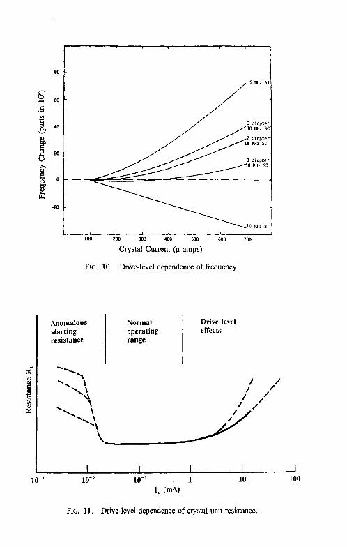
As the drive level (the current through a crystal) increases, the crystal’s amplitude of vibration also increases, and the effects due to the nonlinearities of quartz become more pronounced. Some of the many properties that depend on the drive level are resonance frequency, motional resistance RI, phase noise, frequency-vs-temperature anomalies (called activity dips), and frequency jumps, which are discussed in other sections of this chapter. The drive-level dependence of the resonance frequency, called the amplitude- frequency effect, is illustrated in Fig. 10 [40]. The frequency change with drive level is proportional to the square of the drive current; the coefficient depends on resonator design [41]. Because of the drive-level dependence of frequency, the highest-stability oscillators usually contain some form of automatic level control to minimize frequency changes due to oscillator circuitry changes. At high drive levels, the nonlinear effects also result in an increase in the resistance [35]. Crystals can also exhibit anomalously high starting resistance when the crystal surfaces possess such imperfections as scratches and particulate contamination. Under such conditions, the resistance at low drive levels can be high enough for an oscillator to be unable to start when power is applied. The drive-level dependence of resistance is illustrated in Fig. 11. In addition to the nonlinear effects, a high drive level can also cause a frequency change due to a temperature increase caused by the energy dissipation in the active area of the resonator.
Bulk acoustic wave (BAW) quartz resonators are available in the frequency range of about 1 kHz to 500MHz. Surface acoustic wave (SAW) quartz
Crystal Current @ amps)
FIG. 10. Drive-level dependence of frequency.
10-’
Anomalous starting resistance
Normal operating range
Drive level effects
I I I I I I lo+ 10-l 1 10 100
I, 04
FIG. 11. Drive-level dependence of crystal unit resistance.
John R. Vig and Arthur Ballato
Flexure Mode
Thickness Shear Mode
FIG. 12.
Extensional Mode
Fundamental Mode Thickness Shear
Face Shear Mode
Third Overtone Thickness Shear
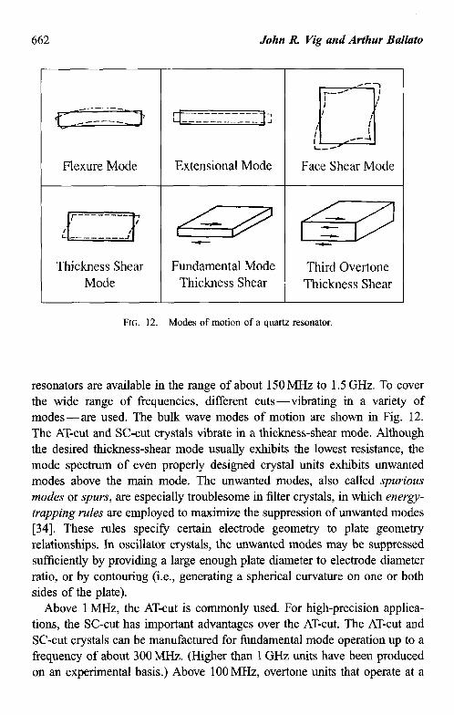
Modes of motion of a quartz resonator.
resonators are available in the range of about 150 MHz to 1.5 GHz. To cover the wide range of frequencies, different cuts-vibrating in a variety of modes-are used. The bulk wave modes of motion are shown in Fig. 12. The AT-cut and SC-cut crystals vibrate in a thickness-shear mode. Although the desired thickness-shear mode usually exhibits the lowest resistance, the mode spectrum of even properly designed crystal units exhibits unwanted modes above the main mode. The unwanted modes, also called sp~vio~s modes or spurs, are especially troublesome in filter crystals, in which energy- trapping rules are employed to maximize the suppression of unwanted modes [34]. These rules specify certain electrode geometry to plate geometty relationships. In oscillator crystals, the unwanted modes may be suppressed sufficiently by providing a large enough plate diameter to electrode diameter ratio, or by contouring (i.e., generating a spherical curvature on one or both sides of the plate).
Above 1 MHz, the AT-cut is commonly used. For high-precision applica- tions, the SC-cut has important advantages over the AT-cut. The AT-cut and SC-cut crystals can be manufactured for fundamental mode operation up to a frequency of about 300 MHz. (Higher than 1 GHz units have been produced on an experimental basis.) Above 100 MHz, overtone units that operate at a
7 Frequency Control Devices 663
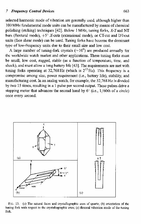
selected harmonic mode of vibration are generally used, although higher than 100 MHz fundamental mode units can be manufactured by means of chemical polishing (etching) techniques [42]. Below 1 MHz, tuning forks, X-Yand NT bars (flextural mode), +5” X-cuts (extensional mode), or CT-cut and DT-cut units (face shear mode) can be used. Tuning forks have become the dominant type of low-frequency units due to their small size and low cost.
A large number of tuning-fork crystals (~10~) are produced annually for the worldwide watch market and other applications. These tuning forks must be small, low cost, rugged, stable (as a function of temperature, time, and shock), and must allow a long battery life [43]. The requirements are met with tuning forks operating at 32,768Hz (which is 215Hz). This frequency is a compromise among size, power requirement (i.e., battery life), stability, and manufacturing cost. In an analog watch, for example, the 32,768 Hz is divided by two 15 times, resulting in a 1 pulse per second output. These pulses drive a stepping motor that advances the second hand by 6” (i.e., 1/6Oth of a circle) once every second.
FIG. 13. (a) The natural faces and crystallographic axes of quartz; (b) orientation of the tuning fork with respect to the crystalIographic axes; (c) flexural vibration mode of the tuning fork.
1 (b) (cl
664 John R. Vig and Arthur Ballato
Figure 13(a) shows the natural faces and crystallographic axes of quartz, and Fig. 13(b) shows the orientation of the tuning fork with respect to these axes. After processing the tuning fork into a resonator, including the deposition of appropriate electrodes and hermetic sealing into an enclosure, and upon excitation with an appropriate oscillator circuit, the tuning fork vibrates in the flexural vibration mode shown in Fig. 13(c).
B. OSCILLATOR CATEGORIES
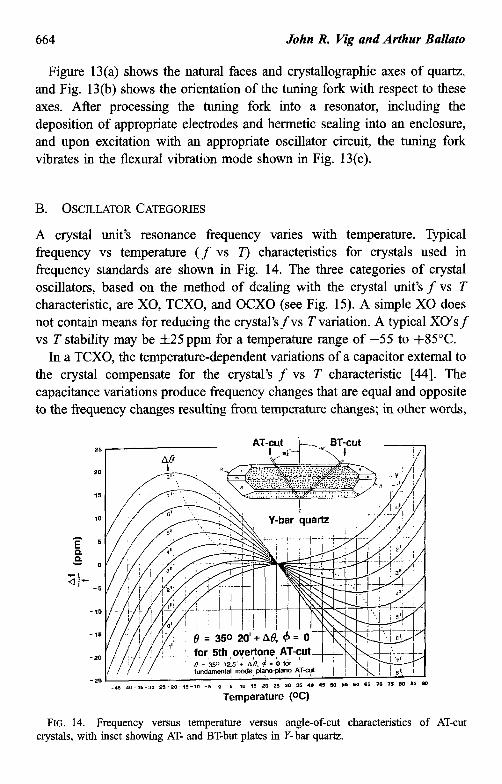
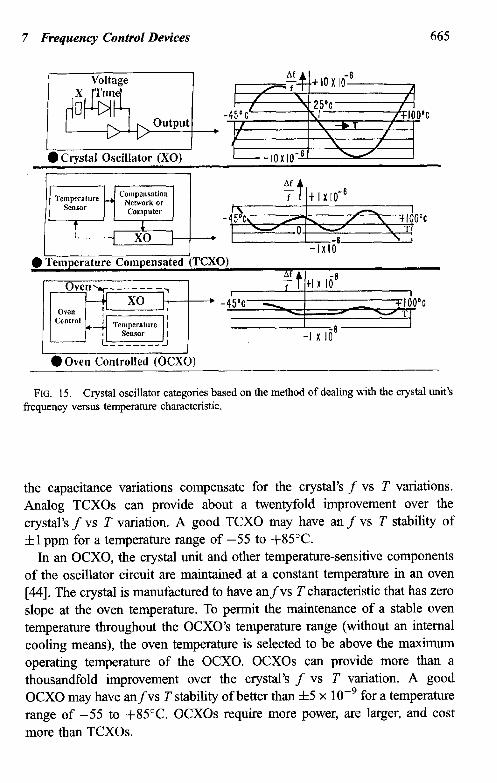
A crystal unit’s resonance frequency varies with temperature. Typical frequency vs temperature (f vs r) characteristics for crystals used in frequency standards are shown in Fig. 14. The three categories of crystal oscillators, based on the method of dealing with the crystal unit’s f vs T characteristic, are X0, TCXO, and OCXO (see Fig. 15). A simple X0 does not contain means for reducing the crystal’sfvs T variation. A typical XO’sf vs T stability may be f25ppm for a temperature range of -55 to +85”C.
In a TCXO, the temperature-dependent variations of a capacitor external to the crystal compensate for the crystal’s f vs T characteristic [44]. The capacitance variations produce frequency changes that are equal and opposite to the frequency changes resulting from temperature changes; in other words,
for 5th overtone AT-cut
Temperature (OC)
FIG. 14. Frequency versus temperature versus angle-of-cut characteristics of AT-cut crystals, with inset showing AT- and BT-but plates in Y-bar quartz.
7 Frequency Control Devices 665
1 0 Crvstal Osciltl
l Temperature Compensated (TCXO)
0 Oven Controlled COCXO)
FIG. 15. Crystal oscillator categories based on the method of dealing with the crystal unit’s frequency versus temperature characteristic.
the capacitance variations compensate for the crystal’s f vs T variations. Analog TCXOs can provide about a twentyfold improvement over the crystal’s f vs T variation. A good TCXO may have an f vs T stability of fl ppm for a temperature range of -55 to +85”C.
In an OCXO, the crystal unit and other temperature-sensitive components of the oscillator circuit are maintained at a constant temperature in an oven [44]. The crystal is manufactured to have anfvs Tcharacteristic that has zero slope at the oven temperature. To permit the maintenance of a stable oven temperature throughout the OCXO’s temperature range (without an internal cooling means), the oven temperature is selected to be above the maximum operating temperature of the OCXO. OCXOs can provide more than a thousandfold improvement over the crystal’s f vs T variation. A good OCXO may have anfvs T stability of better than f5 x 1 OF9 for a temperature range of -55 to +85”C. OCXOs require more power, are larger, and cost more than TCXOs.
666 John R. Vig and Arthur Ballato
A special case of a compensated oscillator is the microcomputer-compen- sated crystal oscillator (MCXO) [45]. The MCXO overcomes the two major factors that limit the stabilities achievable with TCXOs: thermometry and the stability of the crystal unit. Instead of a thermometer that is external to the crystal unit, such as a thermistor, the MCXO uses a much more accurate “self-temperature sensing” method. Two modes of the crystal are excited simultaneously in a dual-mode oscillator. The two modes are combined such that the resulting beat frequency is a monotonic (and nearly linear) function of temperature. The crystal thereby senses its own temperature. To reduce thef vs T variations, the MCXO uses digital compensation techniques: pulse deletion in one implementation, and direct digital synthesis of a compensating frequency in another. The frequency of the crystal is not “pulled,” which allows the use of high-stability (small C,) SC-cut crystal units. A typical MCXO may have anfvs T stability of f2 x lop8 for a temperature range of -55 to +t35v.
C. OSCILLATOR CIRCUIT YES
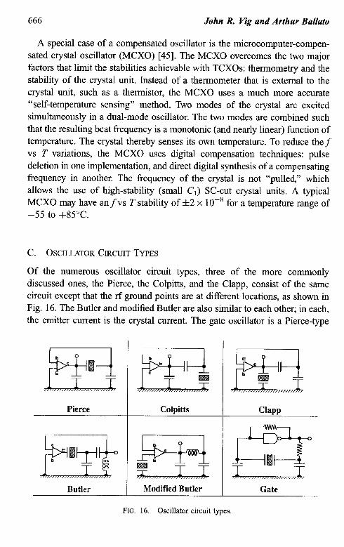
Of the numerous oscillator circuit types, three of the more commonly discussed ones, the Pierce, the Colpitts, and the Clapp, consist of the same circuit except that the rf ground points are at different locations, as shown in Fig. 16. The Butler and modified Butler are also similar to each other; in each, the emitter current is the crystal current. The gate oscillator is a Pierce-type
Pierce
Butler
Colpitts
Modified Butler
Claw
Gate
FIG. 16. Oscillator circuit types.
7 Frequency Control Devices 667
that uses a logic gate plus a resistor in place of the transistor in the Pierce oscillator. (Some gate oscillators use more than one gate.)
Information on designing crystal oscillators can be found in references 1,2, 5, and 7. The choice of oscillator circuit type depends on such factors as the desired frequency stability, input voltage and power, output power and waveform, tunability, design complexity, cost, and the crystal unit’s charac- teristics.
In the Pierce family, the ground point location has a profound effect on the performance. The Pierce configuration is generally superior to the others, e.g., with respect to the effects of stray reactances and biasing resistors, which appear mostly across the capacitors in the circuit rather than the crystal unit. It is one of the most widely used circuits for high-stability oscillators. In the Colpitts configuration, a larger part of the strays appears across the crystal, and the biasing resistors are also across the crystal, which can degrade performance. The Clapp is seldom used because, since the collector is tied directly to the crystal, it is difficult to apply a dc voltage to the collector without introducing losses or spurious oscillations. The Pierce family usually operates at parallel resonance (see Fig. 6), although it can be designed to operate at series resonance by connecting an inductor in series with the crystal. The Butler family usually operates at (or near) series resonance. The Pierce can be designed to operate with the crystal current above or below the emitter current. Gate oscillators are common in digital systems when high stability is not a major consideration. (See the references for more details on oscillator circuits.)
Most users require a sine wave, a TTL-compatible, a CMOS-compatible, or an ECL-compatible output. The latter three can be simply generated from a sine wave.
D. OSCILLATOR INSTABILITIES
1. Accuracy, Stability, and Precision
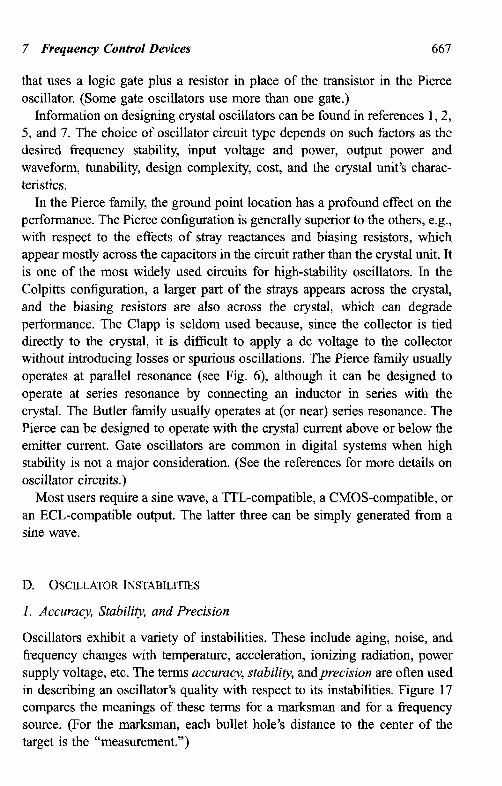
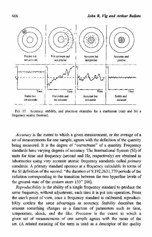
Oscillators exhibit a variety of instabilities. These include aging, noise, and frequency changes with temperature, acceleration, ionizing radiation, power supply voltage, etc. The terms accuracy, stability, andprecision are often used in describing an oscillator’s quality with respect to its instabilities. Figure 17 compares the meanings of these terms for a marksman and for a frequency source. (For the marksman, each bullet hole’s distance to the center of the target is the “measurement.“)
John R Vig and Arthur Ballato
Precise but not accu1-ate
Not accurate and not precise
I
Time
Stable but not accurate
I
Time
Not stable and not accurate
Accurate but not precise
Time
Accurate but not stable
Accurate and precise
FIG. 17. Accuracy, stability, and precision examples for a marksman (top) and for a frequency source (bottom).
Accuracy is the extent to which a given measurement, or the average of a set of measurements for one sample, agrees with the definition of the quantity being measured. It is the degree of “correctness” of a quantity. Frequency standards have varying degrees of accuracy. The International System (SI) of units for time and frequency (second and Hz, respectively) are obtained in laboratories using very accurate atomic frequency standards called primaly standards. A primary standard operates at a frequency calculable in terms of the SI definition of the second: “the duration of 9,192,263 1,770 periods of the radiation corresponding to the transition between the two hyperfine levels of the ground state of the cesium atom 133” [46].
Reproducibility is the ability of a single frequency standard to produce the same frequency, without adjustment, each time it is put into operation. From the user’s point of view, once a frequency standard is calibrated, reproduci- bility confers the same advantages as accuracy. Stability describes the amount something changes as a function of parameters such as time, temperature, shock, and the like. Precision is the extent to which a given set of measurements of one sample agrees with the mean of the set. (A related meaning of the term is used as a descriptor of the quality
7 Frequency Control Devices 669
of an instrument, as in a “precision instrument.” In that context, the meaning is usually defined as accurate and precise, although a precision instrument can also be inaccurate and precise, in which case the instrument needs to be calibrated.)
2. Aging
“Aging” and “drift” have occasionally been used interchangeably in the literature. However, recognizing the “need for common terminology for the unambiguous specification and description of frequency and time standard systems,” the International Radio Consultative Committee (CUR) adopted a glossary of terms and definitions in 1990 [47]. According to this glossary, aging is “the systematic change in frequency with time due to internal changes in the oscillator,” and drift is “the systematic change in frequency with time of an oscillator.” Drift due to aging plus changes in the environment and other factors external to the oscillator. Aging, not drift, is what one denotes in a specification document and what one measures during oscillator evaluation. Drift is what one observes in an application. For example, the drift of an oscillator in a spacecraft might be due to (the algebraic sum of) aging and frequency changes due to radiation, temperature changes in the space- craft, and power supply changes.
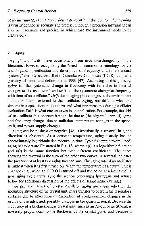
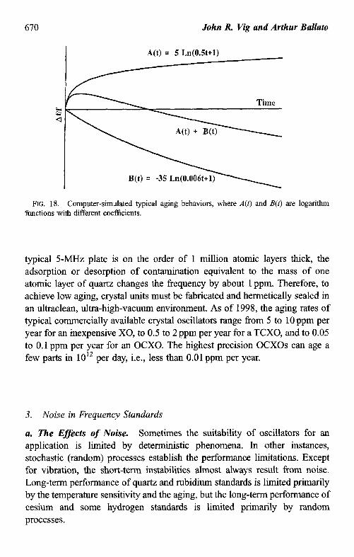
Aging can be positive or negative [48]. Occasionally, a reversal in aging direction is observed. At a constant temperature, aging usually has an approximately logarithmic dependence on time. Typical (computer-simulated) aging behaviors are illustrated in Fig. 18, where A(t) is a logarithmic function and B(t) is the same function but with different coefficients. The curve showing the reversal is the sum of the other two curves. A reversal indicates the presence of at least two aging mechanisms. The aging rate of an oscillator is highest when it is first turned on. When the temperature of a crystal unit is changed (e.g., when an OCXO is turned off and turned on at a later time), a new aging cycle starts. (See the section concerning hysteresis and retrace below for additional discussion of the effects of temperature cycling.)
The primary causes of crystal oscillator aging are stress relief in the mounting structure of the crystal unit, mass transfer to or from the resonator’s surfaces due to adsorption or desorption of contamination, changes in the oscillator circuitry, and, possibly, changes in the quartz material. Because the frequency of a thickness-shear crystal unit, such as an AT-cut or an SC-cut, is inversely proportional to the thickness of the crystal plate, and because a
670 John R Vig and Arthur Ballato
A(t) = 5 Ln(O.St+l)
Time s a
B(t) = -35 Ln(O.O06t+ I
FIG. 18. Computer-simulated typical aging behaviors, where A(t) and B(t) are logarithm functions with different coefficients.
typical ~-MHZ plate is on the order of 1 million atomic layers thick, the adsorption or desorption of contamination equivalent to the mass of one atomic layer of quartz changes the frequency by about 1 ppm. Therefore, to achieve low aging, crystal units must be fabricated and hermetically sealed in an ultraclean, ultra-high-vacuum environment. As of 1998, the aging rates of typical commercially available crystal oscillators range from 5 to 10 ppm per year for an inexpensive X0, to 0.5 to 2 ppm per year for a TCXO, and to 0.05 to 0.1 ppm per year for an OCXO. The highest precision OCXOs can age a few parts in 1012 per day, i.e., less than 0.01 ppm per year.
3. Noise in Frequency Standards
a. The Effects of Noise. Sometimes the suitability of oscillators for an application is limited by deterministic phenomena. In other instances, stochastic (random) processes establish the performance limitations. Except for vibration, the short-term instabilities almost always result from noise. Long-term performance of quartz and rubidium standards is limited primarily by the temperature sensitivity and the aging, but the long-term performance of cesium and some hydrogen standards is limited primarily by random processes.
7 Frequency Control Devices 671
Noise can have numerous adverse effects on system performance. Some of these effects are: (1) it limits the ability to determine the current state and the predictability of precision oscillators (e.g., the noise of an oscillator produces time prediction errors of Y@Z) for prediction intervals of 7); (2) it limits synchronization and syntonization accuracies; (3) it can limit a receiver’s useful dynamic range, channel spacing, and selectivity; (4) it can cause bit errors in digital communications systems; (5) it can cause loss of lock, and limit acquisition and reacquisition capability in phase locked loop systems; and (6) it can limit radar performance, especially Doppler radar.
To characterize the random components of oscillator instability, appropriate statistical measures are necessary. Noise characterization has been reviewed [34,49, 501 and is also the subject of an IEEE standard [51]. The two-sample deviation, denoted by o,,(z), is the measure of short-term instabilities in the time domain. The phase noise, denoted by Z(f), is the measure of instabilities in the frequency domain. It is related to the phase instability, denoted by S,cf), by Z(f)=-&,(f).
b. Noise in Crystal Oscillators. Although the causes of noise in crystal oscillators are not fully understood, several causes of short-term instabilities have been identified. Temperature fluctuations can cause short-term instabil- ities via thermal-transient effects (see Section III.D.4.b concerning dynamicf vs T effects), and via activity dips at the oven set point in OCXOs. Other causes include Johnson noise in the crystal unit, random vibration (see Section III.D.6 concerning acceleration effects in crystal oscillators), noise in the oscillator circuitry (both the active and passive components can be significant noise sources), and fluctuations at various interfaces on the resonator (e.g., in the number of molecules adsorbed on the resonator’s surface).
In a properly designed oscillator, the resonator is the primary noise source close to the carrier and the oscillator circuitry is the primary source far from the carrier. The noise close to the carrier (i.e., within the bandwidth of the resonator) has a strong inverse relationship with resonator Q, such that Z(f) c( l/Q”. In the time domain, cry(t) x (2 x 10e7)/Q at the noise floor. In the frequency domain, the noise floor is limited by Johnson noise, the noise power of which is kT= - 174 dBm/Hz at 290 K. A higher signal (i.e., a higher resonator drive current) will improve the noise floor but not the close-in noise. In fact, for reasons that are not understood fully, above a certain point, higher
672 John R Vig and Arthur Ballato
drive levels usually degrade the close-in noise. For example, the maximum “safe” drive level is about 100 pa for a ~-MHZ fifth overtone AT-cut resonator with Qe 2.5 million. The safe drive current can be substantially higher for high-frequency SC-cut resonators. For example, L?( f ) = - 180 dBc/Hz has been achieved with 100~MHz fifth overtone SC-cut resonators at drive currents e 10 mA. However, such a noise capability is useful only in a vibration-tree laboratory environment. If there is even a slight amount of vibration at the offset frequencies of interest, the vibration-induced noise will dominate the quiescent noise of the oscillator (see Section III.D.6).
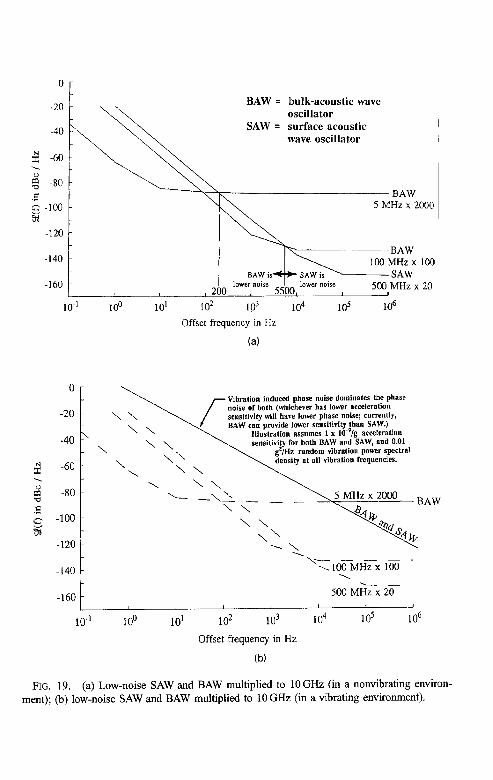
When low noise is required in the microwave (or higher) frequency range, SAW oscillators and dielectric resonator oscillators (DROs) are sometimes used. When compared with multiplied-up (bulk acoustic wave) quartz oscillators, these oscillators can provide lower noise far from the carrier at the expense of poorer noise close to the carrier, poorer aging, and poorer temperature stability. SAW oscillators and DROs can provide lower noise far from the carrier because these devices can be operated at higher drive levels, thereby providing higher signal-to-noise ratios, and because the devices operate at higher frequencies, thereby reducing the “20 log N losses” due to frequency multiplication by N. Noise floors at Z( f ) = - 180 dBc/Hz have been achieved with state-of-the-art SAW oscillators [SO]. Of course, as is the case for high-frequency BAW oscillators, such noise floors are realizable only in environments that are free of vibrations at the offset frequencies of interest. Figures 19(a) and 19(b) show comparisons of state-of-the-art ~-MHZ and lOO- MHz BAW oscillators and a 500-MHz SAW oscillator, multiplied to 10 GHz. Figure 19(a) shows the comparison in a quiet environment, and Figure 19(b) shows it in a vibrating environment.
The short-term stability of TCXOs is temperature (7) dependent and is generally significantly worse than that of OCXOs, for the following reasons:
l The slope of the TCXO crystal’s frequency (f) vs T varies with Z For example, the f vs T slope may be near zero at -2O”C, but it will be -1 ppm/“C at the T extremes. T fluctuations will cause small ffluctua- tions at laboratory ambient Ts, so the stability can be good there, but millidegree fluctuations will cause N 1 Oe9 f fluctuations at the T extremes. The TCXOsfvs T slopes also vary with T; the zeros and maxima can be at any T, and the maximum slopes can be on the order of 1 ppm/“C.
l AT-cut crystal’s thermal transient sensitivity makes the effects of T fluctuations depend not only on the T but also on the rate of change
BAW q bulk-acoustic wave oscillator
SAW = surface acoustic wave oscillator
BAW 5 MHz x 2000
-140 -
-160 -
IO-
BAW 100 MHz x 100
BAW is++ SAW is SAW lower noise ,200 / 5500 lower noise 500 MHz x 20 1
10’ Id Id 104 16 106
Offset frequency in Hz
Oc \ 7 Vibrat’ the phase ion induced phase noise dominates rwise of both (whichever has lower acceleration sensitivity will have lower phase noise; currently, BAW can provide lower sensitivity than SAW.)
Illustration assumes 1 x 10-‘/g scceleratioll sensitivity for both BAW and SAW, and 0.01
&/Hz random vibration power spectral density at ntl vibration frequencies.
-140 I ,- - - - - \ 100 MHz x 100
,
-160
10-I 100
500 M%-xZTi- - I I 4
10’ Id 103 IO4 16 106
Offset Frequency in Hz
(b)
FIG. 19. (a) Low-noise SAW and BAW multiplied to 1OGHz (in a nonvibrating environ- ment); (b) low-noise SAW and BAW multiplied to 10 GHz (in a vibrating environment).
674 John R Vig and Arthur Ballato
of T (whereas the SC-cut crystals typically used in precision OCXOs are insensitive to thermal transients). Under changing T conditions, the T gradient between the T sensor (thermistor) and the crystal will aggravate the problems.
l TCXOs typically use fundamental mode AT-cut crystals, which have lower Q and larger C, than the crystals typically used in OCXOs. The lower Q makes the crystals inherently noisier, and the larger C, makes the oscillators more susceptible to circuitry noise.
l AT-cut crystals’fvs ToRen exhibit activity dips. At the Ts where the dips occur, thefvs T slope can be very high, so the noise due to T fluctuations will also be very high, e.g., 100 x degradation of oY(r) and 304 degradation of phase noise are possible. Activity dips can occur at any T
c. Frequency Jumps. When the frequencies of oscillators are observed for long periods, occasional frequency jumps can be observed. In precision oscillators, the magnitudes of the jumps are typically in the range of 1 OK’ ’ to 10-9. The jumps can be larger in general purpose units. The jumps occur many times a day in some oscillators, and much less than once a day in others. The frequency excursions can be positive or negative. The causes (and cures) are not well understood.
The causes are believed to include nearby spurious resonances, stress relief, changes in surface and electrode irregularities, and noisy active and passive circuit components. The effect can depend on resonator drive level; in some units, frequency jumps can be produced at certain drive levels (but not below or above). Aging affects the incidence. Well-aged units show a lower incidence of jumps than new units.
Environmental effects can also produce jumps. Magnetic field, pressure, temperature, and power transients can produce sudden frequency excursions, as can shock and vibration. It is not unusual, for example, to experience shock and vibration levels of >O.Ol g in buildings as trucks pass by, heavy equipment is moved, boxes are dropped etc. [0.02 g x 10P9/g = 2 x 10P”].
4. Frequency versus Temperature Stability
a. Static Frequency versus Temperature Stability. As an illustration of the effects that temperature can have on frequency stability, Fig. 20 shows the effects of temperature on the accuracy of a typical quartz wristwatch. Near the wrist temperature, the watch can be very accurate because of the frequency of the crystal (i.e., the clock rate) changes very little with temperature. However,
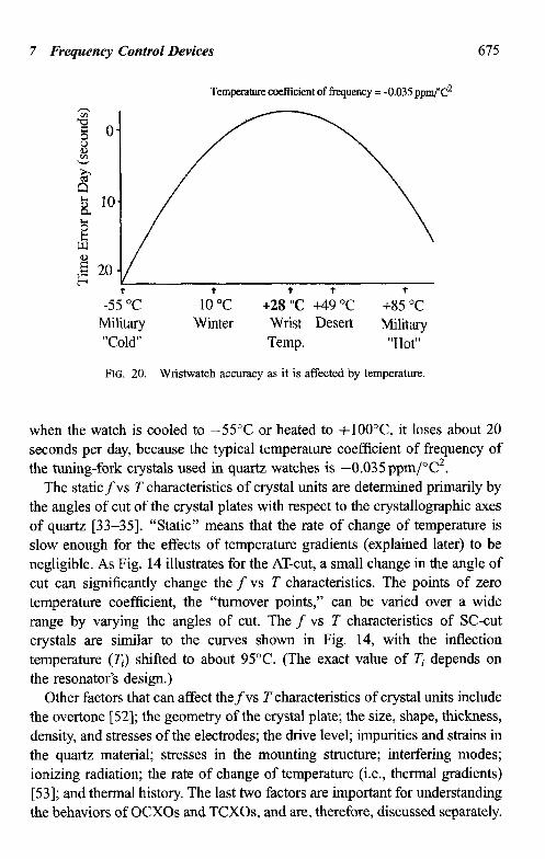
7 Frequency Control Devices 675
Temperature cceffkient of frequency = -0.035 ppm/$
-55 “C Military “Cold”
-10 “C Winter
+28 “C +49 “C Wrist Desert Temp.
+85 “C Military
“Hot”
FIG. 20. Wristwatch accuracy as it is affected by temperature.
when the watch is cooled to -55°C or heated to +lOO”C, it loses about 20 seconds per day, because the typical temperature coefficient of frequency of the tuning-fork crystals used in quartz watches is -0.035 ppm/“C’.
The staticfvs T characteristics of crystal units are determined primarily by the angles of cut of the crystal plates with respect to the crystallographic axes of quartz [33-351. “Static” means that the rate of change of temperature is slow enough for the effects of temperature gradients (explained later) to be negligible. As Fig. 14 illustrates for the AT-cut, a small change in the angle of cut can significantly change the f vs T characteristics. The points of zero temperature coefficient, the “turnover points,” can be varied over a wide range by varying the angles of cut. The f vs T characteristics of SC-cut crystals are similar to the curves shown in Fig. 14, with the inflection temperature (7;:) shifted to about 95°C. (The exact value of z depends on the resonator’s design.)
Other factors that can affect thefvs T characteristics of crystal units include the overtone [52]; the geometry of the crystal plate; the size, shape, thickness, density, and stresses of the electrodes; the drive level; impurities and strains in the quartz material; stresses in the mounting structure; interfering modes; ionizing radiation; the rate of change of temperature (i.e., thermal gradients) [53]; and thermal history. The last two factors are important for understanding the behaviors of OCXOs and TCXOs, and are, therefore, discussed separately.
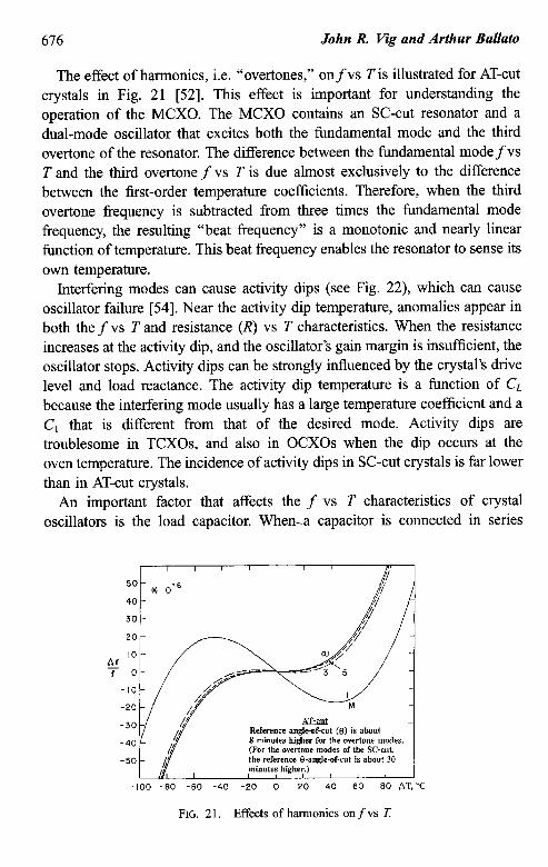
676 John R Vig and Arthur Ballato
The effect of harmonics, i.e. “overtones,” onfvs T is illustrated for AT-cut crystals in Fig. 21 [52]. This effect is important for understanding the operation of the MCXO. The MCXO contains an SC-cut resonator and a dual-mode oscillator that excites both the fundamental mode and the third overtone of the resonator. The difference between the fundamental mode fvs T and the third overtone f vs T is due almost exclusively to the difference between the m-&-order temperature coefficients. Therefore, when the third overtone frequency is subtracted from three times the fundamental mode frequency, the resulting “beat frequency” is a monotonic and nearly linear function of temperature. This beat frequency enables the resonator to sense its own temperature.
Interfering modes can cause activity dips (see Fig. 22), which can cause oscillator failure [54]. Near the activity dip temperature, anomalies appear in both the f vs T and resistance (I?) vs T characteristics. When the resistance increases at the activity dip, and the oscillator’s gain margin is insufficient, the oscillator stops. Activity dips can be strongly influenced by the crystal’s drive level and load reactance. The activity dip temperature is a function of CL because the interfering mode usually has a large temperature coefficient and a Cr that is different from that of the desired mode. Activity dips are troublesome in TCXOs, and also in OCXOs when the dip occurs at the oven temperature. The incidence of activity dips in SC-cut crystals is far lower than in AT-cut crystals.
An important factor that affects the f vs T characteristics of crystal oscillators is the load capacitor. When-.a capacitor is connected in series
Reference angleof-cut (tl) is about 8 minutes higfier for tbo overtone modes. (For the overtone modes of the SC-cut, the reference &angle-of-cut is about 30
-100 -80 -60 -40 -20 0 20 40 60 80 AT, %
FIG. 21. Effects of harmonics on f vs 7:
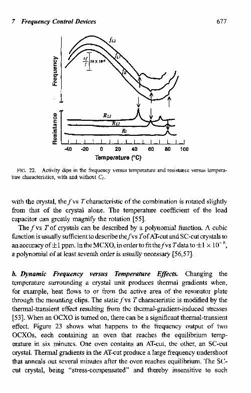
7 Frequency Control Devices 677
40 -20 0 20 40 60 60 100
Temperature (“C)
FIG. 22. Activity dips in the frequency versus temperature and resistance versus tempera- ture characteristics, with and without CL.
with the crystal, thefvs T characteristic of the combination is rotated slightly from that of the crystal alone. The temperature coefficient of the load capacitor can greatly magnify the rotation [55].
The f vs T of crystals can be described by a polynomial function. A cubic function is usually sufficient to describe thefvs Tof AT-cut and SC-cut crystals to an accuracy off 1 ppm. In the MCXO, in order to fit thefvs T data to f 1 x 1 OK’, a polynomial of at least seventh order is usually necessary [56,57].
b. Dynamic Frequency versus Temperature Effects. Changing the temperature surrounding a crystal unit produces thermal gradients when, for example, heat flows to or from the active area of the resonator plate through the mounting clips. The staticfvs T characteristic is modified by the thermal-transient effect resulting from the thermal-gradient-induced stresses [53]. When an OCXO is turned on, there can be a significant thermal-transient effect. Figure 23 shows what happens to the frequency output of two OCXOs, each containing an oven that reaches the equilibrium temp- erature in six minutes. One oven contains an AT-cut, the other, an SC-cut crystal. Thermal gradients in the AT-cut produce a large frequency undershoot that anneals out several minutes after the oven reaches equilibrium. The SC- cut crystal, being “stress-compensated” and thereby insensitive to such
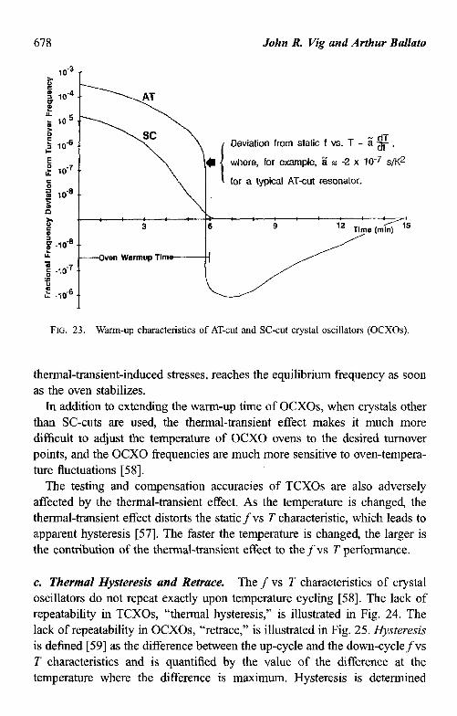
678 John R. Vig and Arthur Ballato
Deviation from static f vs. T = 5 $ ,
where, for example, 5 z -2 x 10e7 s/K2
for a typical AT-cut resonator.
--Oven Warmup Tlm
FIG. 23. Warm-up characteristics of AT-cut and SC-cut crystal oscillators (OCXOs).
thermal-transient-induced stresses, reaches the equilibrium frequency as soon as the oven stabilizes.
In addition to extending the warm-up time of OCXOs, when crystals other than SC-cuts are used the thermal-transient effect makes it much more difficult to adjust the temperature of OCXO ovens to the desired turnover points, and the OCXO frequencies are much more sensitive to oven-tempera- ture fluctuations [58].
The testing and compensation accuracies of TCXOs are also adversely affected by the thermal-transient effect. As the temperature is changed the thermal-transient effect distorts the staticfvs T characteristic, which leads to apparent hysteresis [57]. The faster the temperature is changed, the Iarger is the contribution of the thermal-transient effect to the f vs T performance.
c. Thermal Hysteresis and Retrace. The f vs T characteristics of crystal oscillators do not repeat exactly upon temperature cycling [58]. The lack of repeatability in TCXOs, “thermal hysteresis,” is illustrated in Fig. 24. The lack of repeatability in OCXOs, “retrace, ” is illustrated in Fig. 25. Hysteresis is defined [59] as the difference between the up-cycle and the down-cyclefvs T characteristics and is quantified by the value of the difference at the temperature where the difference is maximum. Hysteresis is determined
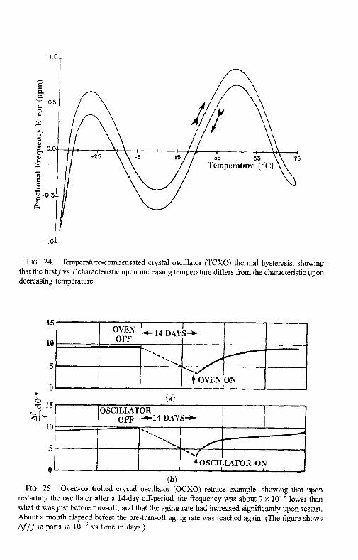
FIG. 24. Temperature-compensated crystal oscillator (TCXO) thermal hysteresis, showing that the firstfvs Tcharacteristic upon increasing temperature differs from the characteristic upon decreasing temperature.
n -; OVEN ON
(a) OSCILLATOR I
OFF 4-14 DAYS+
0 t OSCILLATOR ON
FIG. 25. Oven-controlled crystal oscillator (OCXO) retrace exampIe, showing that upon restarting the oscillator after a 14-day off-period the frequency was about 7 x 10e9 lower than what it was just before turn-off, and that the aging rate had increased significantly upon restart. About a month elapsed before the pre-turn-off aging rate was reached again. (The figure shows Af/f in parts in 10P9 vs time in days.)
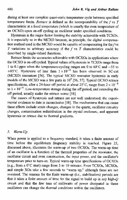
680 John R. Vig and Arthur Ballato
during at least one complete quasi-static temperature cycle between specified temperature limits. Retrace is defined as the nonrepeatability of the f vs T characteristic at a fixed temperature (which is usually the oven temperature of an OCXO) upon on-off cycling an oscillator under specified conditions.
Hysteresis is the major factor limiting the stability achievable with TCXOs. It is especially so in the MCXO because, in principle, the digital compensa- tion method used in the MCXO would be capable of compensating for thefvs T variations to arbitrary accuracy if the f vs T characteristics could be described by single-valued functions.
Retrace limits the accuracies achievable with OCXOs in applications where the OCXO is on-off cycled. Typical values of hysteresis in TCXOs range from 1 to 0.1 ppm when the temperature-cycling ranges are 0 to 60°C and -55 to +85”C. Hysteresis of less than 1 x lo-* has been observed in SC-cut (MCXO) resonators [56]. The typical MCXO resonator hysteresis in early models of the MCXO was a few parts in lo* [56, 571. Typical OCXO retrace specifications, after a 24-hour off period at about 25°C range from 2 x lo-* to 1 x 10P9. Low-temperature storage during the off period, and extending the off period usually make the retrace worse [58].
The causes of hysteresis and retrace are not well understood; the experi- mental evidence to date is inconclusive [58]. The mechanisms that can cause these effects include strain changes, changes in the quartz, oscillator circuitry changes, contamination redistribution in the crystal enclosure, and apparent hysteresis or retrace due to thermal gradients.
5. Warm-Up
When power is applied to a frequency standard it takes a finite amount of time before the equilibrium frequency stability is reached. Figure 23, discussed above, illustrates the warm-up of two OCXOs. The warm-up time of an oscillator is a function of the thermal properties of the resonator, the oscillator circuit and oven construction, the input power, and the oscillator’s temperature prior to turn-on. Typical warm-up time specifications of OCXOs (e.g., from a 0°C start) range from 3 to 10 minutes. Even TCXOs, MCXOs, and simple XOs take a few seconds to “warm up,” although these are not ovenized. The reasons for the finite warm-up (i.e., stabilization) periods are that it takes a finite amount of time for the signal to build up in any high-Q circuit and that the few tens of milliwatts of power dissipated in these oscillators can change the thermal conditions within the oscillators.
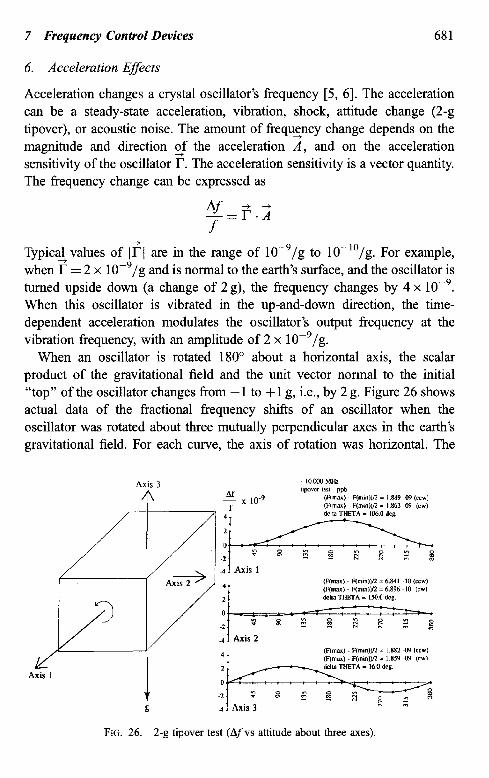
7 Frequency Control Devices 681
6. Acceleration Effects
Acceleration changes a crystal oscillator’s frequency [5, 61. The acceleration can be a steady-state acceleration, vibration, shock, attitude change (2-g tipover), or acoustic noise. The amount of freque+ncy change depends on the magnitude and direction cf the acceleration A, and on the acceleration sensitivity of the oscillator r. The acceleration sensitivity is a vector quantity. The frequency change can be expressed as
Tsicaf values of l?j are in the range of 10e9/g to 10-“/g. For example, when r = 2 x 10P9/g and is normal to the earth’s surface, and the oscillator is turned upside down (a change of 2 g), the frequency changes by 4 x 10W9. When this oscillator is vibrated in the up-and-down direction, the time- dependent acceleration modulates the oscillator’s output frequency at the vibration frequency, with an amplitude of 2 x 10P9/g.
When an oscillator is rotated 180” about a horizontal axis, the scalar product of the gravitational field and the unit vector normal to the initial “top” of the oscillator changes from - 1 to + 1 g, i.e., by 2 g. Figure 26 shows actual data of the fractional frequency shifts of an oscillator when the oscillator was rotated about three mutually perpendicular axes in the earth’s gravitational field. For each curve, the axis of rotation was horizontal. The
FIG. 26. 2-g tipover test (Afvs attitude about three axes).
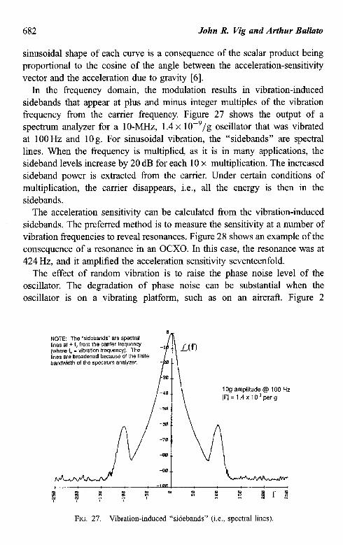
682 John R. Vig and Arthur Ballato
sinusoidal shape of each curve is a consequence of the scalar product being proportional to the cosine of the angle between the acceleration-sensitivity vector and the acceleration due to gravity [6].
In the frequency domain, the modulation results in vibration-induced sidebands that appear at plus and minus integer multiples of the vibration frequency from the carrier frequency. Figure 27 shows the output of a spectrum analyzer for a lo-MHz, 1.4 x 10P9/g oscillator that was vibrated at 100 Hz and 10 g. For sinusoidal vibration, the “sidebands” are spectral lines. When the frequency is multiplied as it is in many applications, the sideband levels increase by 20 dB for each 10 x multiplication. The increased sideband power is extracted from the carrier. Under certain conditions of multiplication, the carrier disappears, i.e., all the energy is then in the sidebands.
The acceleration sensitivity can be calculated from the vibration-induced sidebands. The preferred method is to measure the sensitivity at a number of vibration frequencies to reveal resonances. Figure 28 shows an example of the consequence of a resonance in an OCXO. In this case, the resonance was at 424 Hz, and it amplified the acceleration sensitivity seventeenfold.
The effect of random vibration is to raise the phase noise level of the oscillator. The degradation of phase noise can be substantial when the oscillator is on a vibrating platform, such as on an aircraft. Figure 2
NOTE: The “sidebands” are spectral lines a, f f, from the cartier frequency (whew fv = vibration frequency). The lines am broadened because of the finite bandwidth of the spectrum analyzer.
1 Og amplitude @ 100 Hz Irl = 1.4 x 10.’ per g
FIG. 27. Vibration-induced “sidebands” (i.e., spectral lines).
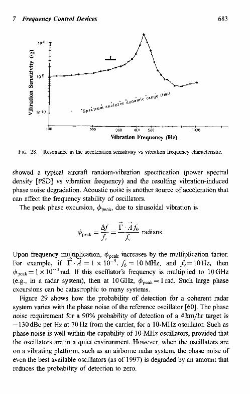
7 Frequency Control Devices 683
4 100 200 3w 400 500
Vibration Frequency (Hz) 1000
FIG. 28. Resonance in the acceleration sensitivity vs vibration frequency characteristic.
showed a typical aircrafl random-vibration specification (power spectral density [PSD] vs vibration frequency) and the resulting vibration-induced phase noise degradation. Acoustic noise is another source of acceleration that can affect the frequency stability of oscillators.
The peak phase excursion, +reak, due to sinusoidal vibration is
.
Upon frequency mu$ipJication, &ek increases by the multiplication factor. For example, if I- . A = 1 x 10e9, f0 = 10 MHz, and fb. = 10 Hz, then &ak = 1 x 10e3 rad. If th’ is oscillator’s frequency is multiplied to 10 GHz (e.g., in a radar system), then at 10 GHz, &,eak = 1 rad. Such large phase excursions can be catastrophic to many systems.
Figure 29 shows how the probability of detection for a coherent radar system varies with the phase noise of the reference oscillator [60]. The phase noise requirement for a 90% probability of detection of a 4km/hr target is - 130 dBc per Hz at 70 Hz from the carrier, for a lo-MHz oscillator. Such as phase noise is well within the capability of IO-MHz oscillators, provided that the oscillators are in a quiet environment. However, when the oscillators are on a vibrating platform, such as an airborne radar system, the phase noise of even the best available oscillators (as of 1997) is degraded by an amount that reduces the probability of detection to zero.
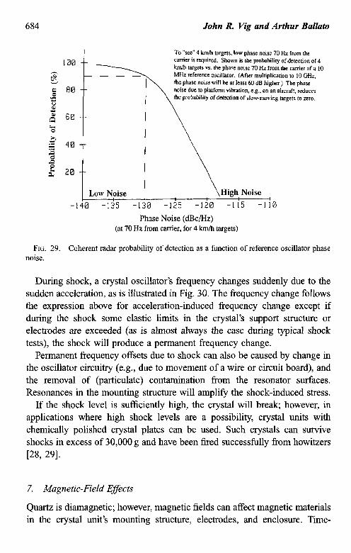
684 John R Vig and Arthur Ballato
To “see” 4 km/h targets. low phase noise 70 Hz from the carrier is required. Shown is the probability of detection of 4 km/h targets vs. the phase noise 70 Hz from the carrier of a 10 MHz reference oscillator. (After multiplication to 10 GHr. the phase noise will be at least 60 dB higher.) The phase noise due to platform vibration, e.g., on an aircraft. reduces the probability of detection of slow-moving targets to zero.
I Low Noise I :\ High Noise
4 -140 -135 -130 -125 -120 -I I5 -110
Phase Noise (et/Hz) (at 70 Hz from carrier, for 4 km/h targets)
FIG. 29. Coherent radar probability of detection as a function of reference oscillator phase noise.
During shock, a crystal oscillator’s frequency changes suddenly due to the sudden acceleration, as is illustrated in Fig. 30. The frequency change follows the expression above for acceleration-induced frequency change except if during the shock some elastic limits in the crystal’s support structure or electrodes are exceeded (as is almost always the case during typical shock tests), the shock will produce a permanent frequency change.
Permanent frequency offsets due to shock can also be caused by change in the oscillator circuitry (e.g., due to movement of a wire or circuit board), and the removal of (particulate) contamination from the resonator surfaces. Resonances in the mounting structure will amplify the shock-induced stress.
If the shock level is sufficiently high, the crystal will break; however, in applications where high shock levels are a possibility, crystal units with chemically polished crystal plates can be used. Such crystals can survive shocks in excess of 30,000 g and have been fired successfully from howitzers [28, 291.
7. Magnetic-Field Efsects
Quartz is diamagnetic; however, magnetic fields can affect magnetic materials in the crystal unit’s mounting structure, electrodes, and enclosure. Time-
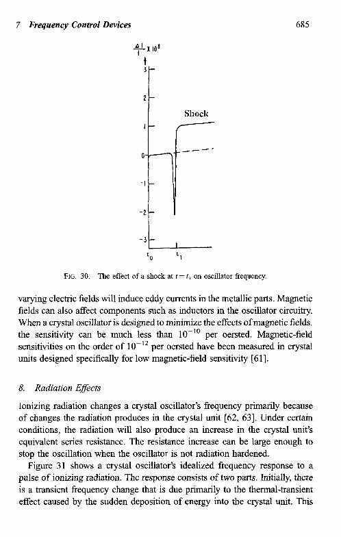
7 Frequency Control Devices 685
2-
Shock I- /
o-q-- _---
-l -
FIG. 30. The effect of a shock at t = t, on oscillator frequency.
varying electric fields will induce eddy currents in the metallic parts. Magnetic fields can also affect components such as inductors in the oscillator circuitry. When a crystal oscillator is designed to minimize the effects of magnetic fields, the sensitivity can be much less than 10-l’ per oersted. Magnetic-field sensitivities on the order of 10-l’ per oersted have been measured in crystal units designed specifically for low magnetic-field sensitivity [61].
8. Radiation Effects
Ionizing radiation changes a crystal oscillator’s frequency primarily because of changes the radiation produces in the crystal unit [62, 631. Under certain conditions, the radiation will also produce an increase in the crystal unit’s equivalent series resistance. The resistance increase can be large enough to stop the oscillation when the oscillator is not radiation hardened.
Figure 31 shows a crystal oscillator’s idealized frequency response to a pulse of ionizing radiation. The response consists of two parts. Initially, there is a transient frequency change that is due primarily to the thermal-transient effect caused by the sudden deposition of energy into the crystal unit. This
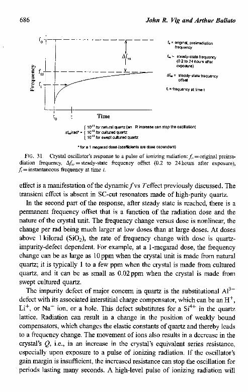
John R. Vig and Arthur Ballato
f. = OrigInal, preirradialion frequency
f, = steady-state frequency (0.2 to 24 hours aRer t%pOSUEt)
Af.. = steady-state frequency offset
ft = fEqxm2y at time t
f 10” for natural quartz (an R increase can stop Ihe oscillation) Af,Jrad’= ( lo‘” for cultured quartz
( lo- for swept cuttured quartz
‘for a 1 megarad dose (coefficients are dose dependent)
FIG. 3 1. Crystal oscillator’s response to a pulse of ionizing radiation: f0 = original preirra- diation frequency, L\f,= steady-state frequency offset (0.2 to 24 hours after exposure),
f t = instantaneous frequency at time t.
effect is a manifestation of the dynamicfvs Teffect previously discussed. The transient effect is absent in SC-cut resonators made of high-purity quartz.
In the second part of the response, after steady state is reached, there is a permanent frequency offset that is a function of the radiation dose and the nature of the crystal unit. The frequency change versus dose is nonlinear, the change per rad being much larger at low doses than at large doses. At doses above 1 kilorad (SiO& the rate of frequency change with dose is quartz- impurity-defect dependent. For example, at a 1-megarad dose, the frequency change can be as large as 10 ppm when the crystal unit is made from natural quartz; it is typically 1 to a few ppm when the crystal is made from cultured quartz, and it can be as small as 0.02ppm when the crystal is made from swept cultured quartz.
The impurity defect of major concern in quartz is the substitutional A13+ defect with its associated interstitial charge compensator, which can be an H+, Li+, or Na+ ion, or a hole. This defect substitutes for a Si4+ in the quartz lattice. Radiation can result in a change in the position of weakly bound compensators, which changes the elastic constants of quartz and thereby leads to a frequency change. The movement of ions also results in a decrease in the crystal’s Q, i.e., in an increase in the crystal’s equivalent series resistance, especially upon exposure to a pulse of ionizing radiation. If the oscillator’s gain margin is insufficient, the increased resistance can stop the oscillation for
i periods lasting many seconds. A high-level pulse of ionizing radiation will
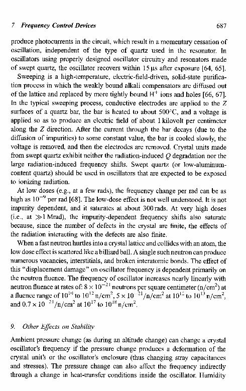
7 Frequency Control Devices 687
produce photocvents in the circuit, which result in a momentary cessation of oscillation, independent of the type of quartz used in the resonator. In oscillators using properly designed oscillator circuitry and resonators made of swept quartz, the oscillator recovers within 15 ps after exposure [64, 651.
Sweeping is a high-temperature, electric-field-driven, solid-state purifica- tion process in which the weakly bound alkali compensators are diffused out of the lattice and replaced by more tightly bound H+ ions and holes [66, 671. In the typical sweeping process, conductive electrodes are applied to the Z surfaces of a quartz bar, the bar is heated to about 5OO”C, and a voltage is applied so as to produce an electric field of about 1 kilovolt per centimeter along the Z direction. After the current through the bar decays (due to the diffusion of impurities) to some constant value, the bar is cooled slowly, the voltage is removed, and then the electrodes are removed. Crystal units made from swept quartz exhibit neither the radiation-induced Q degradation nor the large radiation-induced fi-equency shifts. Swept quartz (or low-ahuninum- content quartz) should be used in oscillators that are expected to be exposed to ionizing radiation.
At low doses (e.g., at a few rads), the frequency change per rad can be as high as lop9 per rad [68]. The low-dose effect is not well understood. It is not impurity dependent, and it saturates at about 300rads. At very high doses (i.e., at >>l Mrad), the impurity-dependent frequency shifts also saturate because, since the number of defects in the crystal are finite, the effects of the radiation interacting with the defects are also finite.
When a fast neutron hurtles into a crystal lattice and collides with an atom, the low dose effect is scattered like a billiard ball. A single such neutron can produce numerous vacancies, interstitials, and broken interatomic bonds. The effect of this “displacement damage” on oscillator frequency is dependent primarily on the neutron fluence. The frequency of oscillator increases nearly linearly with neutron fluence at rates of: 8 x 1 O-2’ neutrons per square centimeter (n/cm2) at a fluence range of 10” to 1012n/cm2, 5 x 10P21/n/cm2 at 1012 to 1013 n/cm2, and 0.7 x 10⁻²¹/n/cm2 at 1017 to 101sn/cm2.
9. Other Effects on Stability
Ambient pressure change (as during an altitude change) can change a crystal oscillator’s frequency if the pressure change produces a deformation of the crystal unit’s or the oscillator’s enclosure (thus changing stray capacitances and stresses). The pressure change can also affect the frequency indirectly through a change in heat-transfer conditions inside the oscillator. Humidity
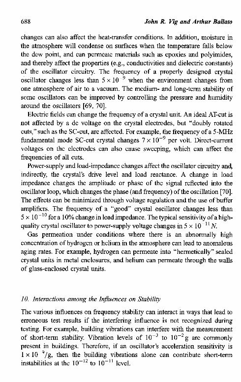
688 John R. Vig and Arthur Ballato
changes can also affect the heat-transfer conditions. In addition, moisture in the atmosphere will condense on surfaces when the temperature falls below the dew point, and can permeate materials such as epoxies and polyimides, and thereby affect the properties (e.g., conductivities and dielectric constants) of the oscillator circuitry. The frequency of a properly designed crystal oscillator changes less than 5 x lop9 when the environment changes from one atmosphere of air to a vacuum. The medium- and long-term stability of some oscillators can be improved by controlling the pressure and humidity around the oscillators [69, 701.
Electric fields can change the frequency of a crystal unit. An ideal AT-cut is not affected by a dc voltage on the crystal electrodes, but “doubly rotated cuts,” such as the SC-cut, are affected. For example, the frequency of a ~-MHZ fundamental mode SC-cut crystal changes 7 x lop9 per volt. Direct-current voltages on the electrodes can also cause sweeping, which can affect the frequencies of all cuts.
Power-supply and load-impedance changes affect the oscillator circuitry and, indirectly, the crystal’s drive level and load reactance. A change in load impedance changes the amplitude or phase of the signal reflected into the oscillator loop, which changes the phase (and frequency) of the oscillation [70]. The effects can be minimized through voltage regulation and the use of buffer amplifiers. The frequency of a “good” crystal oscillator changes less than 5 x lo-” for a 10% change in load impedance. The typical sensitivity of a high- quality crystal oscillator to power-supply voltage changes in 5 x 10-l ’ N
Gas permeation under conditions where there is an abnormally high concentration of hydrogen or helium in the atmosphere can lead to anomalous aging rates. For example, hydrogen can permeate into “hermetically” sealed crystal units in metal enclosures, and helium can permeate through the walls of glass-enclosed crystal units.
10. Interactions among the Influences on Stability
The various influences on frequency stability can interact in ways that lead to erroneous test results if the interfering influence is not recognized during testing. For example, building vibrations can interfere with the measurement of short-term stability. Vibration levels of 10e3 to 1 Op2 g are commonly present in buildings. Therefore, if an oscillator’s acceleration sensitivity is 1 x 10p9/g, then the building vibrations alone can contribute short-term instabilities at the lo-l2 to 10-l ’ level.
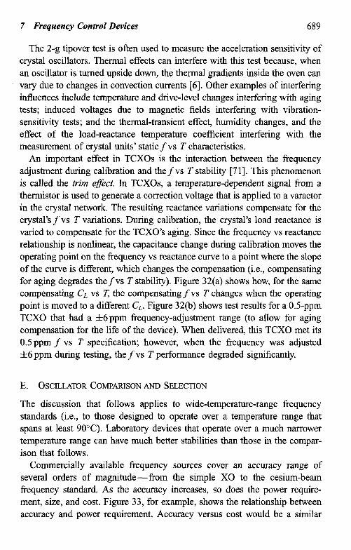
7 Frequency Control Devices 689
The 2-g tipover test is often used to measure the acceleration sensitivity of crystal oscillators. Thermal effects can interfere with this test because, when an oscillator is turned upside down, the thermal gradients inside the oven can vary due to changes in convection currents [6]. Other examples of interfering influences include temperature and drive-level changes interfering with aging tests; induced voltages due to magnetic fields interfering with vibration- sensitivity tests; and the thermal-transient effect, humidity changes, and the effect of the load-reactance temperature coefficient interfering with the measurement of crystal units’ static f vs T characteristics.
An important effect in TCXOs is the interaction between the frequency adjustment during calibration and thefvs T stability [71]. This phenomenon is called the trim e$xt. In TCXOs, a temperature-dependent signal from a thermistor is used to generate a correction voltage that is applied to a varactor in the crystal network. The resulting reactance variations compensate for the crystal’s f vs T variations. During calibration, the crystal’s load reactance is varied to compensate for the TCXO’s aging. Since the frequency vs reactance relationship is nonlinear, the capacitance change during calibration moves the operating point on the frequency vs reactance curve to a point where the slope of the curve is different, which changes the compensation (i.e., compensating for aging degrades thefvs T stability). Figure 32(a) shows how, for the same compensating C, vs T the compensating f vs T changes when the operating point is moved to a different C,. Figure 32(b) shows test results for a OS-ppm TCXO that had a f6ppm frequency-adjustment range (to allow for aging compensation for the life of the device). When delivered, this TCXO met its 0.5 ppm f vs T specification; however, when the frequency was adjusted f6 ppm during testing, the f vs T performance degraded significantly.
E. OSCILLATOR COMPARISONAND SELECTION
The discussion that follows applies to wide-temperature-range frequency standards (i.e., to those designed to operate over a temperature range that spans at least 90%). Laboratory devices that operate over a much narrower temperature range can have much better stabilities than those in the compar- ison that follows.
Commercially available frequency sources cover an accuracy range of several orders of magnitude--from the simple X0 to the cesium-beam frequency standard. As the accuracy increases, so does the power require- ment, size, and cost. Figure 33, for example, shows the relationship between accuracy and power requirement. Accuracy versus cost would be a similar
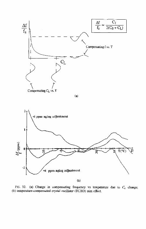
Af i
1 r Compensating CL vs. T
@zGq
2 Compensating f vs. T
J
(a)
FIG. 32. (a) Change in compensating frequency vs temperature due to CL change; (b) temperature-compensated crystal oscillator (TCXO) trim effect.
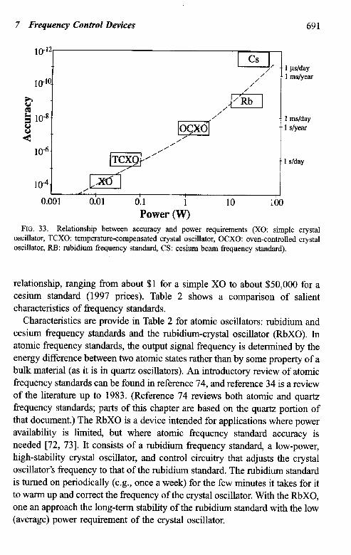
7 Frequency Control Devices 691
cs I _ / 1 p/day / / 1 msfyear
/ / ,m
2 10-s. / / 8 ocxo 4 II
106. ,ppyNR”
10-4. ,1 x5’ /
0.001 0.01 0.1 (4) 10 Power
slyear
s/day
FIG. 33. Relationship between accuracy and power requirements (X0: simple crystal oscillator, TCXO: temperature-compensated crystal oscillator, OCXO: oven-controlled crystal oscillator, RB: rubidium frequency standard, CS: cesium beam frequency standard).
relationship, ranging from about $1 for a simple X0 to about $50,000 for a cesium standard (1997 prices). Table 2 shows a comparison of salient characteristics of frequency standards.
Characteristics are provide in Table 2 for atomic oscillators: rubidium and cesium frequency standards and the rubidium-crystal oscillator (RbXO). In atomic frequency standards, the output signal frequency is determined by the energy difference between two atomic states rather than by some property of a bulk material (as it is in quartz oscillators). An introductory review of atomic frequency standards can be found in reference 74, and reference 34 is a review of the literature up to 1983. (Reference 74 reviews both atomic and quartz frequency standards; parts of this chapter are baaed on the quartz portion of that document.) The RbXO is a device intended for applications where power availability is limited, but where atomic frequency standard accuracy is needed [72, 731. It consists of a rubidium frequency standard, a low-power, high-stability crystal oscillator, and control circuitry that adjusts the crystal oscillator’s frequency to that of the rubidium standard. The rubidium standard is turned on periodically (e.g., once a week) for the few minutes it takes for it to warm up and correct the frequency of the crystal oscillator. With the RbXO, one an approach the long-term stability of the rubidium standard with the low (average) power requirement of the crystal oscillator.
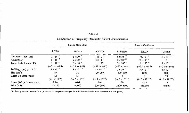
TABLE 2
Comparison of Frequency Standards’ Salient Characteristics
Quartz Oscillators Atomic Oscillators
Accuracy* (per year) Aging/Year Temp. Stab. (range, “C)
Stability, q>(z) (t = 1 s) Size (cm3) Warm-Up Time (min)
Power (W) (at lowest temp.) Price (-$)
TCXO
2 x 10⁻⁶ 5x10⁻⁷ 5x10⁻⁷
(-55 to +85) 1 x 10⁻⁹
10 0.1
(to 1 x 10-y 0.04
l&100
MCXO
5 x 10⁻⁸ 2 x 10⁻⁸ 3 x1o-8
(-55 to f85) 3 x 10P’O
30 0.1
(to 2 x lo-*) 0.04
<lOOO
ocxo
1 x 10-X 5 x 10⁻⁹ 1 x 10⁻⁹
(-55 to +85) 1 x lo-‘* 2G200
4 (to 1 x 10⁻⁸)
0.6 200-2000
Rubidium
5 x lo-‘0 2 x lo-IO 3 x lo-lo
(-55 to +68) 3x lo-‘* 3OC-800
3 (to 5 x lo-‘O)
20 2OOC8000
RbXO
7 x 1o-‘O 2 x lo-‘0 5x1o-'O
(-55 to +85) 5 x lo-‘*
1000
(to 5 x3lo-'") 0.65
<10,000
Cesium
2x lo-”
2 x pn-ll
(-,"",:",;a)
6000 20
(to 2 x lo-“) 30
40,000
* Including environmental effects (note that the temperature ranges for rubidium and cesium are narrower than for quartz).
7 Frequency Control Devices 693
The major questions to be answered in choosing an oscillator include:
1. What frequency accuracy or reproducibility is needed for the system to operate properly?
2. How long must this accuracy be maintained, i.e., will the oscillator be calibrated or replaced periodically, or must the oscillator maintain the required accuracy for the life of the system?
3. Is ample power available, or must the oscillator operate from batteries? 4. What warm-up time, if any, is permissible?
5. What are the environmental extremes in which the oscillator must operate?
6. What is the short-term stability (phase noise) requirement? 7. What is the size constraint?
In relation to the second question, what cost is to be minimized: the initial acquisition cost or the life-cycle cost? Often, the cost of recalibration is far higher than the added cost of an oscillator that can provide calibration-free life. A better oscillator may also allow simplification of the system’s design.
The frequency of the oscillator is another important consideration, because the choice can have a significant impact on both the cost and the performance. Everything else being equal, an oscillator of standard frequency, such as 5 or 10 MHz, for which manufacturers have well-established designs, will cost less than one of an unusual frequency, such as 8.34289MHz. Moreover, for thickness-shear crystals, such as the AT-cut and SC-cut, the lower the frequency, the lower the aging [48]. Since at frequencies much below 5 MHz, thickness-shear crystals become too large for economical manufac- turing, and since all the highest stability oscillators use thickness-shear crystals, the highest-stability commercially available oscillator’s frequency is 5 MHz. Such oscillators will also have the lowest phase noise capability close to the carrier. There are also some excellent lo-MHz oscillators on the market; however, oscillators of much higher frequency than 10 MHz have significantly higher aging rates and phase noise levels close to the carrier than do 5 MHz oscillators. For lowest phase noise far from the carrier, where the signal-to-noise ratio determines the noise level, higher-frequency crystals (e.g., 1OOMHz) can provide lower noise because such crystals can tolerate higher drive levels, thereby allowing higher signal levels.

694 John R. Vig and Arthur Ballato
F. FAILURE h&CHANISMS
Crystal oscillators have no inherent failure mechanisms. Some have operated for decades without failure. Oscillators do fail (“go out of spec”) occasionally for reasons such as:
l Poor workmanship and quality control-e.g., wires that come loose at poor-quality solder joints, leaks into the enclosure, and random failure of components
l Frequency ages to outside the calibration range due to high aging plus insufficient tuning range
l TCXO frequency vs temperature characteristic degrades due to aging and the “trim effect,” and OCXO frequency vs temperature characteristic degrades due to shti of oven set point.
l Oscillation stops or frequency shifts out of range or becomes noisy at certain temperatures, due to activity dips
l Oscillation stops or frequency shifts out of range when exposed to ionizing radiation, due to use of unswept quartz or poor choice of circuit components
l Oscillator noise exceeds specifications, due to vibration induced noise l Crystal breaks under shock, due to insufficient surface finish.
G. SPECIFICATIONS, STANDARDS, TERMS AND DEFINITIONS
There are numerous specifications and standards that relate to frequency control devices. The major organizations responsible for these documents are the Institute of Electrical and Electronics Engineers (IEEE), the International Electrotechnical Commission (IEC), the International Radio Consultative Committee (CCIR), and the U.S. Department of Defense, which maintains the Military Specification (MIL-SPEC) system. A listing of “Specifications and Standards Relating to Frequency Control” can be found in the final pages of the Proceedings of the IEEE Frequency Control Symposium and its predecessor, the Proceedings of the Annual Symposium on Frequency Control. In the 1996 Proceedings, for example 79 such documents are listed [75]. Many of the documents include terms and definitions, some of which are inconsistent. Unfortunately, no single authoritative document exists for terms and definitions relating to frequency standards. The terms and definitions in the CCIR glossary [47], in IEEE Std. 1139 [5 11, and in MIL-O- 55310s Section 6 [59] are the most recent; they address different aspects of
7 Frequency Control Devices 695
the field, and together form a fairly good set of terms and definitions for users of frequency control devices.
The most comprehensive document dealing with the specification of frequency standards is MIL-0-55310 [59]. The evolution of this document over a period of many years has included periodic coordinations between the government agencies that purchase crystal oscillators and the suppliers of those oscillators. The document addresses the specifications of all the oscillator parameters discussed above, plus many others. This specification was written for crystal oscillators. Because the output frequencies of atomic frequency standards originate from crystal oscillators, and because no comparable document exists that addresses atomic standards specifically, MIL-0-553 10 can also serve as a useful guide to specifying atomic standards.
MIL-STD-188-115, Interoperability and Performance Standards for Communications Timing and Synchronization Subsystems, specifies that the standard frequencies for nodal clocks shall be 1 MHz, 5 MHz, or 5 x 2NMHz, where N is an integer. This standard also specifies a 1 -pulse-per-second timing signal of amplitude 10 \! pulse width of 20 ps, rise time less than 20 ns, fall time less than 1 ys; and a 24-bit binary coded decimal (BCD) time code that provides Coordinated Universal Time (UTC) time of day in hours, minutes, and seconds, with provisions for an additional 12 bits for day of the year, and an additional four bits for describing the figure of merit (FOM) of the time signal. The FOMs range from BCD character 1 for better than 1 ns accuracy to BCD character 9 for “greater than 10 ms of fault” [76].
IV. Related Devices
A. CRYSTAL FILTERS
Quartz crystal units are used as selective components in crystal filters [77]. With the constraint imposed by the equivalent circuit of Fig. 3, filter design techniques can provide bandpass or bandstop filters with a range of char- acteristics. Crystal filters exhibit low insertion loss, high selectivity, and excellent temperature stability.
Filter crystals are designed to have only one strong resonance in the region of operation, with all other responses (unwanted modes) attenuated as much as possible. The application of energy-trapping theory [39,77] can provide such a response. If electrode size and thickness are selected in accordance with that theory, the energy of the main response is trapped between the electrodes, whereas the unwanted modes are untrapped and propagate toward the edge of the crystal resonator, where their energy is dissipated. It is
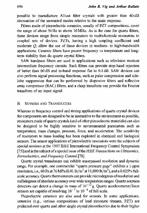
696 .Tohn R Vig and Arthur Ballato
possible to manufacture AT-cut filter crystals with greater than 40-dB attenuation of the unwanted modes relative to the main response.
Filters made of piezoelectric ceramics, usually of PZT compositions, cover the range of about 50 Hz to above 10 MHz. As is the case for quartz filters, these devices range from simple resonators to multielectrode resonators to coupled sets of devices. PZTs, having a high coupling coefficient and moderate Q, allow the use of these devices in medium- to high-bandwidth applications. Ceramic filters have poorer frequency vs temperature and long- term stability than do quartz crystal filters.
SAW bandpass filters are used in applications such as television receiver intermediate frequency circuits. Such filters can provide stop-band rejection of better than 60 dB and in-band response flat to 0.1 dB. SAW devices can also perform signal processing functions, such as pulse compression and side- lobe suppression that can be performed by dispersive filters and reflective array compressor (RAC) filters, and a chirp transform can provide the Fourier transform of an input signal.
B. SENSORS AND TRANSDUCERS
Whereas in frequency control and timing applications of quartz crystal devices the components are designed to be as insensitive to the environment as possible, resonators made of quartz crystals (and of other piezoelectric materials) can also be designed to be highly sensitive to environmental parameters such as temperature, mass changes, pressure, force, and acceleration. The sensitivity of resonators to mass loading has been exploited in chemical and biological sensors. The sensor applications of piezoelectric resonators were the subjects of special sessions at the 1997 IEEE International Frequency Control Symposium [75] and is the subject ofa special issue ofthe IEEE Transactions on Ultrasonics, Ferroelectrics, and Frequenq Control [78].
Quartz crystal transducers can exhibit unsurpassed resolution and dynamic range. For example, one commercial “quartz pressure gage” exhibits a 1-ppm resolution, i.e., 60 Pa at 76 MPa (0.01 lb/in2 at 11,000 lb/in2), and a 0.025% full- scale accuracy. Quartz thermometers can provide microdegrees of resolution and millidegrees of absolute accuracy over wide temperature ranges. Quartz sorption detectors can detect a change in mass of lo-l2 g. Quartz accelerometer/force sensors are capable of resolving 10m7 to lo-’ of full scale.
Piezoelectric ceramics are also used for sensors. In some applications, ceramics (e.g., various compositions of lead zirconate titanate, PZT) are preferred over quartz and other single crystal piezoelectrics due to their higher
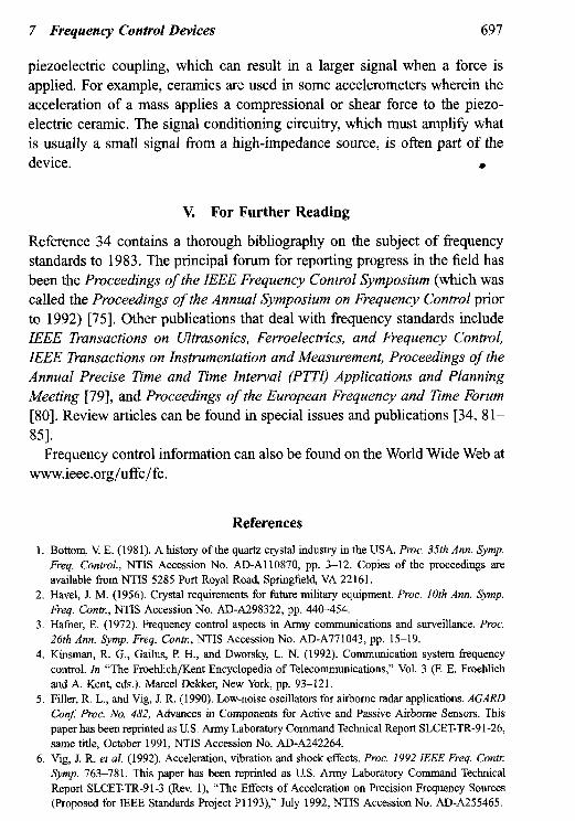
7 Frequency Control Devices 697
piezoelectric coupling, which can result in a larger signal when a force is applied. For example, ceramics are used in some accelerometers wherein the acceleration of a mass applies a compressional or shear force to the piezo- electric ceramic. The signal conditioning circuitry, which must amplify what is usually a small signal from a high-impedance source, is often part of the device. .
V. For Further Reading
Reference 34 contains a thorough bibliography on the subject of frequency standards to 1983. The principal forum for reporting progress in the field has been the Proceedings of the IEEE Frequency Control Symposium (which was called the Proceedings of the Annual Symposium on Frequency Control prior to 1992) [75]. Other publications that deal with frequency standards include IEEE Transactions on Ultrasonics, Ferroelectrics, and Frequency Control, IEEE Transactions on Instrumentation and Measurement, Proceedings of the Annual Precise Time and Time interval (PTTI) Applications and Planning Meeting [79], and Proceedings of the European Frequency and Time Forum [80]. Review articles can be found in special issues and publications 134, 81- 851.
Frequency control information can also be found on the World Wide Web at www.ieee.org/uffc/fc.
References
1. Bottom, V E. (1981). A history of the quarts crystal industry in the USA. Proc. 35th Ann. Symp. Freq. Control., NTIS Accession No. AD-A110870, pp. 3-12. Copies of the proceedings are available from NTIS 5285 Port Royal Road, Springfield, VA 22161.
2. Havel, .I. M. (1956). Crystal requirements for fumre military equipment. Proc. 10th Ann. Symp. Freq. Conk, NTIS Accession No. AD-A298322, pp. 440-454.
3. Hather, E. (1972). Fmquency control aspects in Army communications and surveillance. Proc. 26th Ann. Symp. Freq. Conh., NTIS Accession No. AD-A771043, pp. 15-19.
4. Kinsman, R. G., Gailus, P H., and Dworsky, L. N. (1992). Communication system frequency control. In “The Froehlich/Kent Encyclopedia of Telecommunications,” Vol. 3 (F. E. Froehlich and A. Kent, eds.). Marcel Dekker, New York, pp. 93-121.
5. Filler, R. L., and Vig, .I. R. (1990). Low-noise oscillators for airborne radar applications. AGARD ConJ Proc. No, 482, Advances in Components for Active and Passive Airborne Sensors. This paper has been reprinted as U.S. Army Laboratory Command Technical Report SLCET-TR-91-26, same title, October 1991, NTIS Accession No. AD-A242264.
6. Vig, J. R. et al. (1992). Acceleration, vibration and shock effects. Proc. 1992 IEEE Freq. Con@ Symp. 7633781. This paper has been reprint&l as U.S. Army Laboratory Command Technical Report SLCET-TR-91-3 (Rev. l), “The Effects of Acceleration on Precision Frequency Sources (Proposed for IEEE Standards Project P1193),” July 1992, NTIS Accession No. AD-A255465.
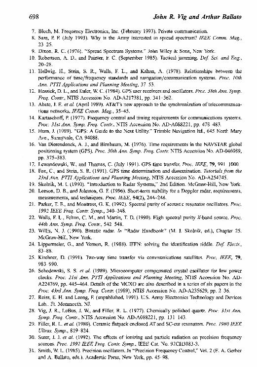
698 John R Vig and Arthur Ballato
7. Bloch, M. Frequency Electronics, Inc. (February 1993). Private communication. 8. Sass, P. F. (July 1993). Why is the Army interested in spread spectrum? IEEE Comm. Mug.,
23-25. 9. Dixon, R. C. (1976). “Spread Spectrum Systems.” John Wiley & Sons, New York.
10. Robertson, A. D., and Painter, E C. (September 1985). Tactical jamming. Def: Sci. and Eng., 20-28.
11. Hellwig, H., Stein, S. R., Walls, F. L., and Kahan, A. (1978). Relationships between the performance of time/frequency standards and navigation/communication systems. Proc. 10th Ann. PTTI Applications and Planning Meeting, 37-53.
12. Hessick, D. L., and Euler, W. C. (1984). GPS user receivers and oscillators. Proc. 38th Ann. Symp. Freq. Co&r, NTIS Accession No. AD-A217381, pp. 341-362.
13. Abate, J. E. et al. (April 1989). AT&T’s new approach to the synchronization of telecommunica- tions networks. IEEE Comm. Mug., 35-45.
14. Kartaschoff, P (1977). Frequency control and timing requirements for communications systems. Pvoc. 31st Ann. Sump. Fveq. Co&:, NTIS Accession No. AD-A088221, pp. 478483.
15. Hum, J. (1989). “GPS: A Guide to the Next Utility.” Trimble Navigation ltd., 645 North Mary Ave., Sunnyvale, CA 94088.
16. Van Dierendonck, A. J., and Birnbaum, M. (1976). Time requirements in the NAVSTAR global positioning system (GPS). Proc. 30th Ann. @mp. Freq. Conk NTIS Accession No. AD-046089, pp. 375-383.
17. Lewandowski, W., and Thomas, C. (July 1991). GPS time transfer. Proc. IEEE, 79, 991-1000. 18. Fox, C., and Stein, S. R. (1991). GPS time determination and dissemination. Tutorials from the
23rd Ann. PTTI Applications and Planning Meeting, NTIS Accession No. AD-A254745. 19. Skolnik, M. I. (1990). “Introduction to Radar Systems,” 2nd Edition. McGraw-Hill, New York. 20. Leeson, D. B., and Johnson, G. E (1996). Short-term stability for a Doppler radar; requirements,
measurements, and techniques. Proc. IEEE, 54(2), 244-248. 21. Parker, T. E., and Montress, G. K. (1992). Spectral purity of acoustic resonator oscillators. Proc.
1992 IEEE Freq. Contr Symp., 340-348. 22. Walls, E L., Felton, C. M., and Martin, T. D. (1990). High spectral purity X-band source. Proc.
44th Ann. Symp. Freq. Con@, 542-548. 23. Willis, N. J. (1990). Bistatic radar. In “Radar Handbook” (M. I. Skolnik, ed.), Chapter 25.
McGraw-Hill, New York. 24. Lippermeier, G., and Vernon, R. (1988). IFFN: solving the identification riddle. IIe$ Electr,
83-88. 25. Kirchner, D. (1991). Two-way time transfer via communications satellites. Proc. IEEE, 79,
983-990. 26. Schodowski, S. S. et al. (1989). Microcomputer compensated crystal oscillator for low power
clocks. Proc. 2Ist Ann. PTTI Applications and Planning Meeting, NTIS Accession No. AD- A224769, pp. 445464. Details of the MCXO are also described in a series of six papers in the Pvoc. 43rd Ann. Symp. Freq. Conk (1989), NTIS Accession No. AD-A235629, pp. 2-36.
27. Reiss, E. H. and Leong, E (unpublished, 1991). U.S. Army Electronics Technology and Devices Lab., Ft. Monmouth, NJ.
28. Vig, J. R., LeBus, J. W., and Filler, R. L. (1977). Chemically polished quartz. Proc. 3Ist Ann. Symp. Freq. Con@, NTIS Accession No. AD-A08822 1, pp. 13 l-143.
29. Filler, R. L. et al. (1980). Ceramic flatpack enclosed AT and SC-cut resonators. Proc. 1980 ZEEE Ultras. Sjmp., 8 19-824.
30. Suter, J. J. et al. (1992). The effects of ionizing and particle radiation on precision frequency sources. PRX 1992 IEEE Freq. Conk Symp., IEEE Cat. No. 92CH3083-3.
3 1. Smith, W. L. (1985). Precision oscillators. In “Precision Frequency Control,” Vol. 2 (E. A. Gerber and A. Ballato, eds.). Academic Press, New York, pp. 45-98.
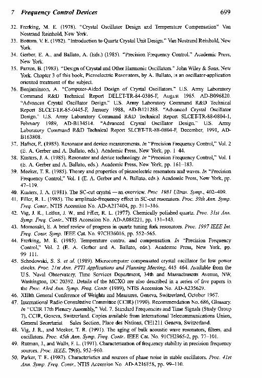
7 Frequency Control Devices 699
32. Frerking, M. E. (1978). “Crystal Oscillator Design and Temperature Compensation” Van Nostrand Reinhold New York.
33. Bottom, V E. (1982). “Introduction to Quartz Crystal Unit Design.” Van Nostrand Reinhold, New York.
34. Gerber, E. A., and Ballato, A. (Eds.) (1985). “Precision Frequency Control.” Academic Press, New York.
35. Parzen, B. (1983). “Design of Crystal and Other Harmonic Oscillators.” John Wiley & Sons, New York. Chapter 3 of this book, Piezoelectric Resonators, by A. Ballato, is an oscillator-application oriented treatment of the subject.
36. Benjaminson, A. “Computer-Aided Design of Crystal Oscillators.” U.S. Army Laboratory Command R&D Technical Report DELET-TR-84-0386-F, August 1985. AD-B096820. “Advances Crystal Oscillator Design.” U.S. Army Laboratory Command R&D Technical Report SLCET-TR-85-0445-E January 1988, AD-B121288. “Advanced Crystal Oscillator Design.” U.S. Army Laboratory Command R&D Technical Report SLCET-TR-88-0804-1, February 1989, AD-B134514. “Advanced Crystal Oscillator Design.” U.S. Army Laboratory Command R&D Technical Report SLCET-TR-88-0804-F, December, 1991, AD- B163808.
37. Hafner, E. (1985). Resonator and device measurements. In “Precision Frequency Control,” Vol. 2 (E. A. Gerber and A. Ballato, eds.). Academic Press, New York, pp. 144.
38. Kusters, J. A. (1985). Resonator and device technology. In “Precision Frequency Control,” Vol. 1 (E. A. Gerber and A. Ballato, eds.). Academic Press, New York, pp. 161-183.
39. Meeker, T. R. (1985). Theory and properties of piezoelectric resonators and waves. In “Precision Frequency Control,” Vol. 1 (E. A. Gerber and A. Ballato, eds.). Academic Press, New York, pp. 47-l 19.
40. Kusters, J. A. (1981). The SC-cut crystal-an overview. Pmt. 1981 Ultras. Symp., 402409. 41. Filler, R. L. (1985). The amplitude-frequency effect in SC-cut resonators. PRX. 39th Ann. Symp.
Freq. Con@, NTIS Accession No. AD-A217404, pp. 311-316. 42. Vig, J. R., LeBus, J. W., and Filler, R. L. (1977). Chemically polished quartz. Proc. 31st Ann.
Symp. Freq. Con&, NTIS Accession No. AD-A088221, pp. 131-143. 43. Momosaki, E. A brief review of progress in quartz tuning fork resonators. Proc. 1997 IEEE ht.
Freq. Con& Symp. IEEE Cat. No. 97CH36016, pp. 5522565. 44. Frerking, M. E. (1985). Temperature control and compensation. In “Precision Frequency
Control,” Vol. 2 (E. A. Gerber and A. Ballato, eds.). Academic Press, New York, pp. 99111.
45. Schodowski, S. S. et al. (1989). Microcomputer compensated crystal oscillator for low power clocks. Proc. 21st Ann. PTTI Applications and Planning Meeting, 445-464. Available from the U.S. Naval Observatory Time Services Department, 34th and Massachusetts Avenue, NW, Washington, DC 20392. Details of the MCXO are also described in a series of five papers in the Proc. 43rd Ann. Symp. Freq. Conk (1989), NTIS Accession No. AD-A235629.
46. XIIIth General Conference of Weights and Measures, Geneva, Switzerland, October 1967. 47. International Radio Consultative Committee (CCIR) (1990). Recommendation No. 686, Glossary.
In “CCIR 17th Plenary Assembly,” Vol. 7. Standard Frequencies and Time Signals (Study Group 7), CCIR, Geneva, Switzerland. Copies available from International Telecommunications Union, General Secretariat - Sales Section, Place des Nations, CH1211 Geneva, Switzerland.
48. Vig, J. R., and Meeker, T. R. (1991). The aging of bulk acoustic wave resonators, filters, and oscillators. Proc. 45th Ann. Symp. Freq. Conti, IEEE Cat. No. 91CH2965-2, pp. 777101.
49. Rutman, J., and Walls, F. L. (1991). Characterization of frequency stability in precision frequency sources. Proc. IEEE, 79(6), 952-960.
50. Parker, T. E. (1987). Characteristics and sources of phase noise in stable oscillators. Proc. 41st Ann. Symp. Freq. Conk, NTIS Accession No. ADA216858, pp. 99-110.
700 * John R Vig and Arthur Ballato
51. IEEE Standard Definitions of Physical Quantities for Fundamental Frequency and Time Metrology-Random Instabilities, IEEE Std. 1139. IEEE, 445 Hoes Lane, Piscataway, NJ 08854, U.S.A.
52. Ballato, A., and Lukaszek, T. (1975). Higher order temperature coefficients of frequency of mass- loaded piezoelectic crystal plates. Proc. 29th Ann. Symp. Freq. Con&, NTIS Accession No. AD- A017466, pp. l&25.
53. Ballato, A., and Vig, J. R. (1978). Static and dynamic frequency-temperature behavior of singly and doubly rotated, oven-controlled quartz resonators. Pmt. 32nd Ann. Symp. Freq. Conk, NTIS Accession No. AD-A955718, pp. 180-188.
54. Ballato, A., and Tilton, R. (1978). Electronic activity dip measurement. IEEE Trans. Ins& and Meas., IM-27, 59-65.
55. Ballato, A. (1978). Frequency-temperature-load capacitance behavior of resonators for TCXO applications. IEEE Trans. Son. Ulfros., SU-25, 185-191.
56. Filler, R. L. (1991). Frequency-temperature considerations for digital temperature compensation. Proc. 45th Ann. Symp. Freq. Con&, IEEE Cat. No. 87CH2965-2, pp. 398-+04.
57. Filler, R. L. (1988). Measurement and analysis of thermal hysteresis in resonators and TCXOs. Pmt. 42nd Ann. Symp. Freq. Con&, NTIS Accession No. AD-A217275, pp. 380-388.
58. Kusters, J. A,, and Vig, J. R. (1990). Thermal hysteresis in quartz resonators-a review. Proc. 44th Ann. &mp. Freq. Conk, IEEE Catalog No. 9OCH2818-03, pp. 165-175.
59. U.S. Department of Defense, Military Specification, Oscillators, Crystal, Genera1 Specification for MIL-PRF-553 10. The Iatest revision is available from Military Specifications and Standards, 700 Robbins Ave., Bldg. 4D, Philadelphia, PA 1911 l-5094. Full text of this document also available at http://www.dscc.dla.mi~o~~s,~ilSpec~istDocs.~p?BasicDoc=~L-P~-55310
60. Taylor, J. (August 8, 1980). Effects of crystal reference oscillator phase noise in a vibratory environment,” Technical Memorandum 2799-1011. Motorola, SOTAS Engineering Development Section, Radar Operations. The Stand-Off Target Acquisition System (SOTAS) was a helicopter- borne coherent radar system that was being developed for the US. Army; the program was canceled before completion. To meet the 90% probability of detection goal for 4km/h targets while operating from a helicopter, the system required a reference oscillator acceleration sensitivity of 4 x lo-l2 perg, which was (and in 1997, still is) about hundredfold beyond the state of the art.
61. Brendel, R. (1996). Influence of magnetic field on quartz crystal resonators. IEEE Trans. Ultrason., Fewoelec., and Freq. &I, 43, 818-831.
62. King, J. C., and Koehler, D. R. (1985). Radiation effects on resonators. In “Precision Frequency Control,” Vol. 2 (E. A. Gerber and A. Ballato, eds.). Academic Press, New York, pp. 147-159.
63. Suter, J. J. et al. (1992). The effects of ionizing and particle radiation on precision frequency sources. Proc. 1992 IEEE Freq. Con& Symp., IEEE Cat. No. 92CH3083-3.
64. King, J. C., and Sander, H. H. (1973). Rapid annealing of frequency change in high frequency crystal resonators following pulsed X-irradiation at room temperature. Proc. 27th Ann. Symp. Freq. Con&, NTIS Accession No. AD-771042, pp. 117-l 19.
65. Paradysz, R. E., and Smith, W. L. (1973). Crystal controlled oscillators for radiation environ- ments. Proc. 27th Ann. Symp. Freq. Con&, NTIS Accession No. AD-771042, pp. 120-123.
66. Martin, J. J. (1988). Electrodiffosion (sweeping) of ions in quarts. IEEE Trans. Ultrason., Ferroelec., and Freq. Ctrl, 35(3), May IEEE CA&dog SSCH2588-2, pp. 228-296.
67. Gualtieri, J. G. (1989). Sweeping quartz crystals. Pruc. 1989 IEEE Ultras. Symp., 381-391. 68. Flanagan, T. M., Leadon, R. E., and Shannon, D. L. (1986). Evaluation of mechanisms for low-
dose frequency shifts in crystal oscillators. Proc. 40th Ann. Symp. Freq. Con&, NTIS Accession no. AD-A235435, pp. 127-133.
69. Walls, F. L. (1988). The influence of pressure and humidity on the medium and long-term frequency stability of quartz oscillators. Pmt. 42nd Ann. Symp. Freq. Conk, NTIS Accession No. AD-A217725, pp. 279-283.
7 Frequency Con&l Devices 701
70. Walls, F. L., and Vig, .I. R. (1995). Fundamental limits on the frequency stabilities of crystal oscillators. IEEE Trans. Ultras., Ferroelec., and Freq. Ctrl, 42, 576589.
71. Filler et a2. (1989). Specification and measurement of the frequency versus temperature characteristics of crystal oscillators. Proc. 43rd Ann. S*vmp. Freq. &I, NTIS Accession No. AD-A235629, pp. 253-256.
72. Vig, .I. R., and Rosati, V J. (1984). The rubidium-crystal oscillator hybrid development program. Pnx. 16th Ann. PTTl Applications and Planning Meeting, 157-165.
73. Riley, W. J., and Vaccaro, J. R. (1987). A rubidium-crystal oscillator (RbXO). IEEE Trans. Ultrason.. Fertvelec., and Freq. CM, UFFC-34, 612-6 18.
74. Stein, S. R., and Vig, J. R. (1992). Communications frequency standards. In “The Froehlich/Kent Encyclopedia of Telecommunications,” Vol. 3 (F. E. Froehlich and A. Kent, eds.). Marcel Dekker, New York, pp. 445-500. A reprint of this chapter is available under the title “Frequency Standards for Communications,” as U.S. Army Laboratory Command Technical Report SLCET-TR-91-2 (Rev. 1), October 1991, NTIS Accession No. AD-A24321 1.
75. The Proceedings of the IEEE International Frequency Control Symposium and its predecessor, the Proceedings of the Annual Symposium on Frequency Control, have been published since the tenth symposium in 1956. The latest volumes are available from the IEEE, 445 Hoes Lane, Piscataway, NJ 08854. The earlier volumes are available from the National Technical Information Service, 5285 Port Royal Road, Sills Building, Springfield., VA 22161. Ordering information for all the Proceedings can be found on the World Wide Web at www.ieee.org/uffc/fc (e.g., the Proceedings of the I996 IEEE International Frequency Control Symposium is available tiom the IEEE, Cat. No. 96CH35935).
76. U.S. Department of Defense, Military Standard MIL-STD-188-115, “Interoperability and Performance Standards for Communications Timing and Synchronization Subsystems.” The latest revision is available from Military Specifications and Standards, 700 Robbins Avenue, Building 4D, Philadelphia, PA ; 19 11 l-5094.
77. Smythe, R. C., and Wagers, R. S. (1985). Piezoelectric and electromechanical filters. In “Precision Frequency Control,” Vol. 2 (E. A. Gerber and A. Ballato, eds.). Academic press, New York, pp. 185-269.
78. IEEE Trans. Ultras., Ferroelec., and Freq. C&l., to be published in late 1998. 79. The Proceedings of the Annual Precise lbne and Time Interval (PTTq Applications and Planning
Meeting are available from the U.S. Naval Observatory, Time Services Department, 34th and Massachusetts Ave., N.W., Washington, DC 20392-5100. The latest volumes are also available
t from the National Technical Information Service, 5285 Port Royal Road, Sills Building, Spring- field, VA 22161.
80. The Proceedings of the European Frequency and Time Forum are available from the Swiss Foundation for Research in Metrology (FSRM), Rue de I’Grangerie 8, CH-2000 Neuchatel, Switzerland.
8 1. IEEE Trans. Ultras., Ferroelec., and Freq. Ctrl, LJFFC-34, November 1987. 82. IEEE Trans. Ultras., Ferroelec., and Freq. Ctrl, UFFC-35, May 1988. 83. Kroupa, V F. (Ed.) (1983). “Frequency Stability: Fundamentals and Measurement.” IEEE Press,
New York. 84. Sullivan, D. B. et al. (Eds.). “Characterization of clocks and oscillators.” National Institute of
Standards and Technology Technical Note 1337. National Institute of Standards and Technology, Boulder, CO 80303-3328.
85. Proc. IEEE, Special Issue on Time and Frequency, 79(7), July 1991.