Embed Size (px)
Citation preview
2522/FMH/FR/V1
7th
January 2014
Frequency Band Support for Future Mobile Handsets
Ofcom
Final Report
Ægis Systems Limited Future Mobile Handsets Final Report
ii 2522/FMH/FR/V1
Table of Contents
0 EXECUTIVE SUMMARY ....................................................................... 1
0.1 Introduction ........................................................................................................ 1
0.2 Trends in multi-band support ........................................................................... 1
0.3 Current global status of LTE frequency bands ............................................... 2
0.4 Technical challenges associated with supporting new frequency
bands ................................................................................................................... 4
0.5 Commercial and cost implications of new-band or technology
deployment ......................................................................................................... 6
0.6 Conclusions ........................................................................................................ 8
1 INTRODUCTION ................................................................................. 11
2 TRENDS IN MULTI-BAND SUPPORT ...................................................... 13
2.1 Evolution of cellular frequency allocations ..................................................... 13
2.2 Current global status of LTE frequency bands ............................................... 15
2.3 Evolution of multi-band handset support ........................................................ 16
2.4 Balancing multi-band support and device performance ............................... 16
3 TECHNICAL CHALLENGES ASSOCIATED WITH SUPPORTING NEW
FREQUENCY BANDS .......................................................................... 18
3.1 Frequency limitations of cellular phone RF architecture .............................. 18
3.1.1 Introduction...................................................................................................... 18
3.1.2 Antennas ......................................................................................................... 21
3.1.3 Switches .......................................................................................................... 21
3.1.4 Filters and duplexers ....................................................................................... 22
3.1.5 Amplifiers......................................................................................................... 23
3.1.6 RFIC and Transceiver Module configuration constraints ................................ 24
3.1.7 Baseband processing ...................................................................................... 26
3.1.8 Conclusions ..................................................................................................... 26
3.2 Implications of new technology requirements ................................................ 27
3.2.1 Introduction...................................................................................................... 27
3.2.2 Carrier Aggregation ......................................................................................... 28
Ægis Systems Limited Future Mobile Handsets Final Report
2522/FMH/FR/V1 iii
3.2.3 MIMO ............................................................................................................... 31
3.2.4 Co-existence between LTE and other technologies ....................................... 32
3.3 Catering for additional bands above 6 GHz .................................................... 32
3.4 Relative difficulty of adopting new bands ....................................................... 33
3.5 Implications of extending existing bands ....................................................... 35
3.6 Future innovations that might facilitate multi-band support ......................... 37
3.6.1 Tunable devices using variable / switched capacitors .................................... 37
3.6.2 RF MEMS ........................................................................................................ 38
3.6.3 Materials innovation ........................................................................................ 38
4 COMMERCIAL AND COST IMPLICATIONS OF NEW-BAND OR
TECHNOLOGY DEPLOYMENT ............................................................... 40
4.1 Costs associated with new bands and technologies ..................................... 40
4.1.1 Non-recurring engineering (NRE) costs .......................................................... 41
4.1.2 Bill of Materials (BOM) trends ......................................................................... 42
4.2 Other commercial considerations .................................................................... 43
4.2.1 Implications of regional variants ...................................................................... 43
4.2.2 Influence of multi-national operators on frequency band and technology
support ............................................................................................................ 45
4.2.3 Mitigating the impact of regional variation ....................................................... 45
4.2.4 Time to Market ................................................................................................ 46
4.2.5 The impact of RFIC vendor consolidation on multi band support ................... 47
5 CONCLUSIONS .................................................................................. 48

Ægis Systems Limited Future Mobile Handsets Final Report
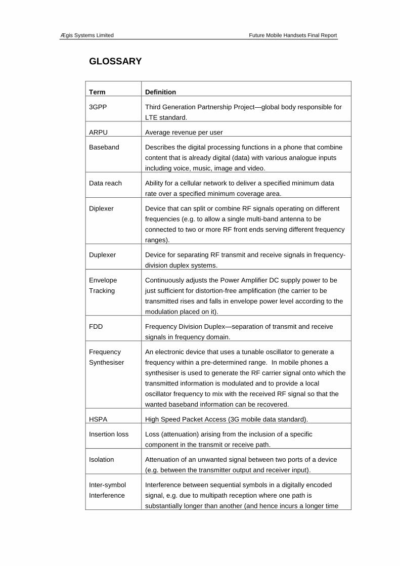
GLOSSARY
Term Definition
3GPP Third Generation Partnership Project—global body responsible for
LTE standard.
ARPU Average revenue per user
Baseband Describes the digital processing functions in a phone that combine
content that is already digital (data) with various analogue inputs
including voice, music, image and video.
Data reach Ability for a cellular network to deliver a specified minimum data
rate over a specified minimum coverage area.
Diplexer Device that can split or combine RF signals operating on different
frequencies (e.g. to allow a single multi-band antenna to be
connected to two or more RF front ends serving different frequency
ranges).
Duplexer Device for separating RF transmit and receive signals in frequency-
division duplex systems.
Envelope
Tracking
Continuously adjusts the Power Amplifier DC supply power to be
just sufficient for distortion-free amplification (the carrier to be
transmitted rises and falls in envelope power level according to the
modulation placed on it).
FDD Frequency Division Duplex—separation of transmit and receive
signals in frequency domain.
Frequency
Synthesiser
An electronic device that uses a tunable oscillator to generate a
frequency within a pre-determined range. In mobile phones a
synthesiser is used to generate the RF carrier signal onto which the
transmitted information is modulated and to provide a local
oscillator frequency to mix with the received RF signal so that the
wanted baseband information can be recovered.
HSPA High Speed Packet Access (3G mobile data standard).
Insertion loss Loss (attenuation) arising from the inclusion of a specific
component in the transmit or receive path.
Isolation Attenuation of an unwanted signal between two ports of a device
(e.g. between the transmitter output and receiver input).
Inter-symbol
Interference
Interference between sequential symbols in a digitally encoded
signal, e.g. due to multipath reception where one path is
substantially longer than another (and hence incurs a longer time
Ægis Systems Limited Future Mobile Handsets Final Report
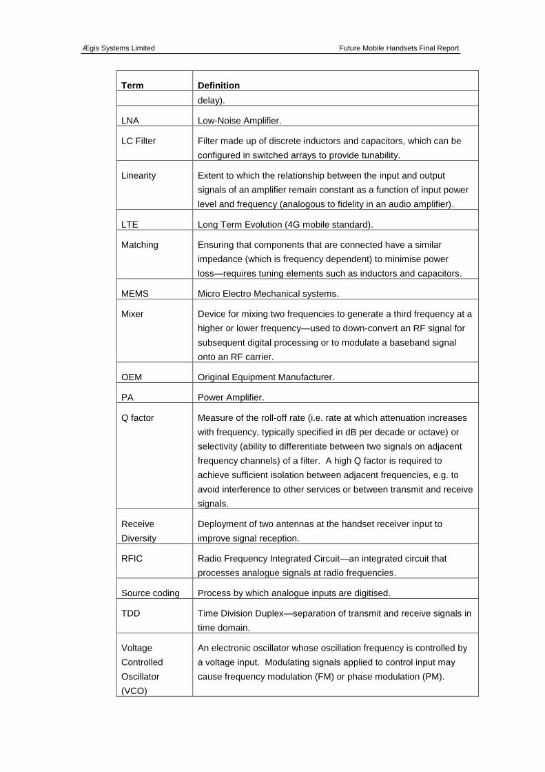
Term Definition
delay).
LNA Low-Noise Amplifier.
LC Filter Filter made up of discrete inductors and capacitors, which can be
configured in switched arrays to provide tunability.
Linearity Extent to which the relationship between the input and output
signals of an amplifier remain constant as a function of input power
level and frequency (analogous to fidelity in an audio amplifier).
LTE Long Term Evolution (4G mobile standard).
Matching Ensuring that components that are connected have a similar
impedance (which is frequency dependent) to minimise power
loss—requires tuning elements such as inductors and capacitors.
MEMS Micro Electro Mechanical systems.
Mixer Device for mixing two frequencies to generate a third frequency at a
higher or lower frequency—used to down-convert an RF signal for
subsequent digital processing or to modulate a baseband signal
onto an RF carrier.
OEM Original Equipment Manufacturer.
PA Power Amplifier.
Q factor Measure of the roll-off rate (i.e. rate at which attenuation increases
with frequency, typically specified in dB per decade or octave) or
selectivity (ability to differentiate between two signals on adjacent
frequency channels) of a filter. A high Q factor is required to
achieve sufficient isolation between adjacent frequencies, e.g. to
avoid interference to other services or between transmit and receive
signals.
Receive
Diversity
Deployment of two antennas at the handset receiver input to
improve signal reception.
RFIC Radio Frequency Integrated Circuit—an integrated circuit that
processes analogue signals at radio frequencies.
Source coding Process by which analogue inputs are digitised.
TDD Time Division Duplex—separation of transmit and receive signals in
time domain.
Voltage
Controlled
Oscillator
(VCO)
An electronic oscillator whose oscillation frequency is controlled by
a voltage input. Modulating signals applied to control input may
cause frequency modulation (FM) or phase modulation (PM).
Ægis Systems Limited Future Mobile Handsets Final Report
2522/FMH/FR/V1 1
0 EXECUTIVE SUMMARY
0.1 Introduction
This report describes the findings of a study carried out for Ofcom by Aegis Systems
and RTT Programmes, addressing the key factors affecting multi-band support in
future cellular handset devices, in particular the likely relationship between the
number of frequency bands supported and the RF cost and performance of a user
device over the next ten to fifteen years. While the study reflects the views of the
authors, the findings are based largely on discussions held with the following
organisations, to whom we extend our gratitude:
Agilent, Anite, Antenova, Avago, Cambridge University (graphene research team),
Cavendish Kinetics, DelfMEMS, EE, GSA, MediaTek, Nujira, Telefonica, Pulse
Electronics, Skyworks, Surrey University, TDK Epcos, Testime, U Blox, Vodafone,
Wispry.
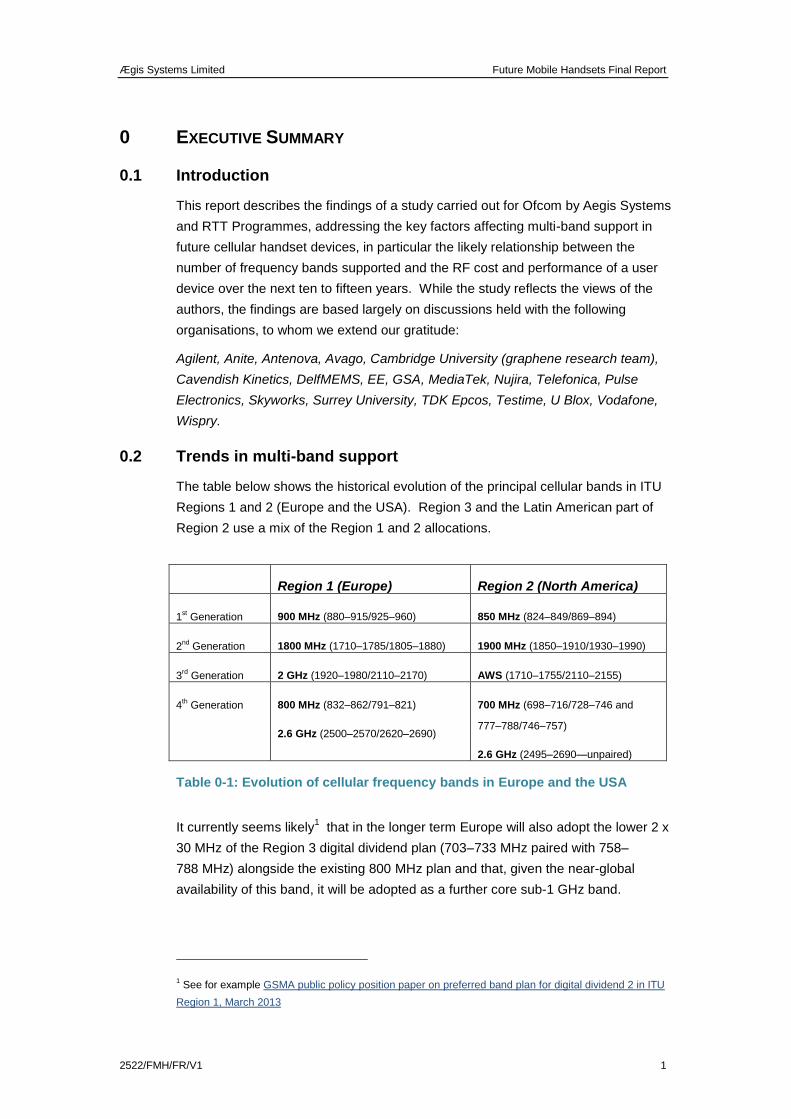
0.2 Trends in multi-band support
The table below shows the historical evolution of the principal cellular bands in ITU
Regions 1 and 2 (Europe and the USA). Region 3 and the Latin American part of
Region 2 use a mix of the Region 1 and 2 allocations.
Region 1 (Europe) Region 2 (North America)
1st Generation 900 MHz (880–915/925–960) 850 MHz (824–849/869–894)
2nd
Generation 1800 MHz (1710–1785/1805–1880) 1900 MHz (1850–1910/1930–1990)
3rd Generation 2 GHz (1920–1980/2110–2170) AWS (1710–1755/2110–2155)
4th Generation 800 MHz (832–862/791–821)
2.6 GHz (2500–2570/2620–2690)
700 MHz (698–716/728–746 and
777–788/746–757)
2.6 GHz (2495–2690—unpaired)
Table 0-1: Evolution of cellular frequency bands in Europe and the USA
It currently seems likely1 that in the longer term Europe will also adopt the lower 2 x
30 MHz of the Region 3 digital dividend plan (703–733 MHz paired with 758–
788 MHz) alongside the existing 800 MHz plan and that, given the near-global
availability of this band, it will be adopted as a further core sub-1 GHz band.
1 See for example GSMA public policy position paper on preferred band plan for digital dividend 2 in ITU
Region 1, March 2013
Ægis Systems Limited Future Mobile Handsets Final Report
2 2522/FMH/FR/V1
In addition to the new bands associated with 3rd
and 4th generation cellular
technologies, there has also been a migration of these technologies into legacy 1st
and 2nd
generation bands—for example, UMTS (3G) is now widely deployed in the
900 MHz band and LTE (4G) in the 1800 MHz band. Long-term support for GSM
(2G) in these bands is also likely to be required to facilitate international roaming in
countries with limited 3G / 4G availability, for example.
Hence over time handsets are required to support new bands associated with new
technologies, while continuing to support earlier bands both for the original legacy
technologies and the newer technologies as these migrate into those bands.
0.3 Current global status of LTE frequency bands
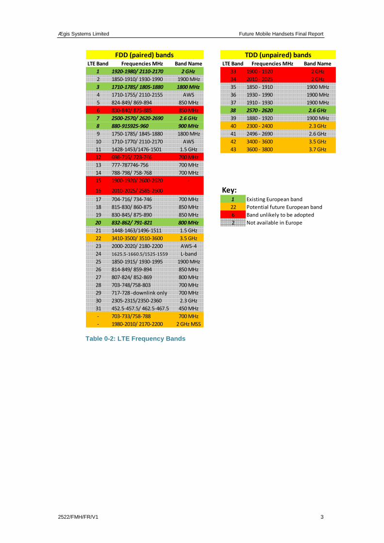
Currently a total of 43 different bands are defined in the LTE standards. Some of
these are “core” bands that are either already deployed or are likely to be deployed
in mainstream devices (depending on region), whereas others are specific to
particular national markets or are no longer relevant as they have been superseded
by other bands.
The table below lists the 43 current LTE bands plus two further bands that we
consider may become available in the future. The colours indicate whether or not
the band is currently, or likely to become, available for use in Europe. Those bands
marked as unlikely to be adopted are either obsolete (because they have been
superseded by other, wider frequency bands), have been rejected by the 3GPP
standards body (Bands 15 / 16) or are long-standing 3G allocations that have never
been used (Bands 12, 33 and 34).
A number of these bands also support legacy technologies (e.g. GSM, UMTS).
Note that there is currently no designated band 32—this is likely to be assigned to a
future FDD band (e.g. the 2 GHz MSS band or a European 700 MHz band). Bands
15 and 16 are also likely to be re-assigned to other frequency bands in the future.
Ægis Systems Limited Future Mobile Handsets Final Report
2522/FMH/FR/V1 3
Table 0-2: LTE Frequency Bands
LTE Band Frequencies MHz Band Name LTE Band Frequencies MHz Band Name
1 1920-1980/ 2110-2170 2 GHz 33 1900 - 1920 2 GHz
2 1850-1910/ 1930-1990 1900 MHz 34 2010 - 2025 2 GHz
3 1710-1785/ 1805-1880 1800 MHz 35 1850 - 1910 1900 MHz
4 1710-1755/ 2110-2155 AWS 36 1930 - 1990 1900 MHz
5 824-849/ 869-894 850 MHz 37 1910 - 1930 1900 MHz
6 830-840/ 875-885 850 MHz 38 2570 - 2620 2.6 GHz
7 2500-2570/ 2620-2690 2.6 GHz 39 1880 - 1920 1900 MHz
8 880-915925-960 900 MHz 40 2300 - 2400 2.3 GHz
9 1750-1785/ 1845-1880 1800 MHz 41 2496 - 2690 2.6 GHz
10 1710-1770/ 2110-2170 AWS 42 3400 - 3600 3.5 GHz
11 1428-1453/1476-1501 1.5 GHz 43 3600 - 3800 3.7 GHz
12 698-716/ 728-746 700 MHz
13 777-787746-756 700 MHz
14 788-798/ 758-768 700 MHz
15 1900-1920/ 2600-2620 -
16 2010-2025/ 2585-2600 - Key:17 704-716/ 734-746 700 MHz 1 Existing European band
18 815-830/ 860-875 850 MHz 22 Potential future European band
19 830-845/ 875-890 850 MHz 6 Band unlikely to be adopted
20 832-862/ 791-821 800 MHz 2 Not available in Europe
21 1448-1463/1496-1511 1.5 GHz
22 3410-3500/ 3510-3600 3.5 GHz
23 2000-2020/ 2180-2200 AWS-4
24 1625.5-1660.5/1525-1559 L-band
25 1850-1915/ 1930-1995 1900 MHz
26 814-849/ 859-894 850 MHz
27 807-824/ 852-869 800 MHz
28 703-748/758-803 700 MHz
29 717-728 -downlink only 700 MHz
30 2305-2315/2350-2360 2.3 GHz
31 452.5-457.5/ 462.5-467.5 450 MHz
- 703-733/758-788 700 MHz
- 1980-2010/ 2170-2200 2 GHz MSS
FDD (paired) bands TDD (unpaired) bands
Ægis Systems Limited Future Mobile Handsets Final Report
4 2522/FMH/FR/V1
A contemporary high-end smart phone such as the iPhone 5 supports seven or
eight bands in one device. The phones are shipped in seven regional variants
which between them cover fifteen bands and seven different combinations of
technology. By comparison, ten years ago a high-end multimedia phone typically
supported five cellular bands and two technologies. The implication is that
additional bands have been supported within a single handset platform at a rate of
three every ten years.
In addition, phones are increasingly required to support ancillary radio technologies
such as Bluetooth, Wi-Fi and GPS. These technologies are generally supported on
a separate chip to the RF front end and therefore have less impact on RF
performance than adding other cellular bands or technologies, although are
themselves subject to interference from cellular transmit signals and this can make
the RF design more challenging.
0.4 Technical challenges associated with supporting new frequency
bands
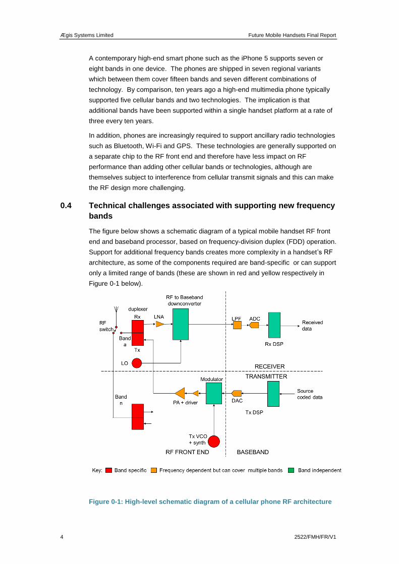
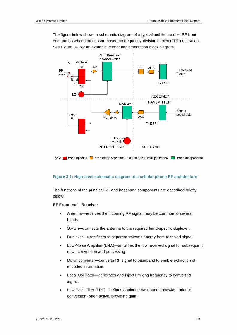
The figure below shows a schematic diagram of a typical mobile handset RF front
end and baseband processor, based on frequency-division duplex (FDD) operation.
Support for additional frequency bands creates more complexity in a handset’s RF
architecture, as some of the components required are band-specific or can support
only a limited range of bands (these are shown in red and yellow respectively in
Figure 0-1 below).
Figure 0-1: High-level schematic diagram of a cellular phone RF architecture

Ægis Systems Limited Future Mobile Handsets Final Report
2522/FMH/FR/V1 5
In a TDD transceiver the duplexers are replaced by an additional RF switch which
alternates the antenna connection between the transmitter and receiver, but filtering
is still required at the input and output to prevent out-of-band noise and signals
being transmitted.
A number of RF components are particularly frequency sensitive and act as
constraints on the addition of new bands, including:
Antennas—performance degrades as bandwidth increases to support more
bands, especially below 1 GHz.
Switches—required to route signals between a multi-band antenna and the
various band-specific duplexers. Each additional switch path to support a
new band adds loss and degrades linearity, particularly affecting 3G/4G
performance.
Filters and Duplexers—duplex filters that separate input and output
signals have a maximum bandwidth of approximately 4 per cent of the
centre frequency and each additional band generally requires an additional
filter2.
Amplifiers—are employed in both the transmitters and receivers of mobile
handsets. Non-linearity (which introduces signal distortion) increases with
amplifier bandwidth, limiting the number of bands that can be served by a
single amplifier. Three amplifiers are typically required to cover the 700–
900 MHz, 1800–2100 MHz and 2300–2700 MHz ranges.
RF filter and switch performance are the main constraints on expanding the number
of bands, as an additional filter / switch combination is required for each band. As
well as adding cost and complexity, this degrades the RF sensitivity of the device by
typically 1 dB per additional band. This is sufficient to reduce the typical data rate
for users by as much as 10–20% or to require a corresponding increase in the
number of network base stations to maintain coverage and data reach3 in existing
bands.
Adding new bands also makes it more challenging to support new capabilities such
as Carrier Aggregation (CA)4. CA requires duplication of the RF front end and much
of the baseband circuitry to deal independently with the two carriers. The LTE
standards already make provision for up to 43 bands globally and at least 50 carrier
2 The exception is where a band is effectively a variant of an existing, wider frequency band—see Table
0-4.
3 ‘Data reach’ is the ability to deliver a specified minimum data rate over a specified minimum coverage
area.
4 CA provides the ability to achieve higher peak bit rates and to achieve higher downlink / uplink
asymmetry (reflecting traffic demand trends) by combining unpaired downlink-only spectrum with an
existing paired band.
Ægis Systems Limited Future Mobile Handsets Final Report
6 2522/FMH/FR/V1
aggregation options. These numbers are likely to grow in the longer term (5–15
years) as more new cellular bands are identified. Each aggregation option requires
the development of option-specific testing, with significant implications for test costs
and time to market. The simultaneous handling of two separate RF signals also
increases the risk of intermodulation products in the device, leading to potential
performance degradation.
One development that could reduce the cost and complexity of multi-band devices
and facilitate the incorporation of additional bands in the future is the replacement of
band-specific devices such as filters with a tunable device that that can cover a
much wider range of frequencies. These can be realised using arrays of fixed
capacitors which can be switched to provide the necessary variability for tuning, but
with current technology the switches would incur a performance penalty. RF Micro
Electro Mechanical Systems (MEMS) may in future lead to improved switch RF
performance but this would be challenging as they require high voltages (of the
order of 30 V) to work efficiently and are mechanical devices which are required to
meet onerous duty cycles in a hostile (hot) operational environment.
Tunability also compromises the filter performance, with tunable filters likely to have
a significantly worse out-of-band rejection, making co-existence with adjacent-band
services more difficult.
Otherwise, significant longer-term performance improvements and/or cost
reductions in RF technology are likely to depend at least in part on innovative new
materials, such as graphene; however, this is considered as being at least 15 years
in the future.
0.5 Commercial and cost implications of new-band or technology
deployment
The addition of more frequency bands or technology variants to a handset will
inevitably introduce extra cost, which can be broadly divided into two areas:
product development (non-recurring engineering)
production (bill of materials).
Historically, non-recurring engineering (NRE) costs have risen by approximately an
order of magnitude for each generation of mobile technology and the estimated
NRE associated with a major new 4G mobile handset development is currently
estimated at between 2 and 3 billion US dollars5. NRE costs are therefore a key
determinant of supply-chain economics and are a function of both the number of
bands and technology complexity.
A tear-down analysis of Apple’s iPhone 4S and iPhone 5 (the former having 2G/3G
support only, the latter also having 4G) indicates that the addition of 4G LTE
5 Source: RTT estimate
Ægis Systems Limited Future Mobile Handsets Final Report
2522/FMH/FR/V1 7
technology and the additional bands to support this led to an increase of
approximately $10 or 40% in the bill of materials (BOM) for the RF and baseband
processing, mostly relating to baseband system support costs. For the iPhone 4S,
the RF / baseband BOM accounted for up to 12.5% of the total device BOM ($188
for the base model), whereas for the iPhone 5 this increased to 17% of the total
($199).
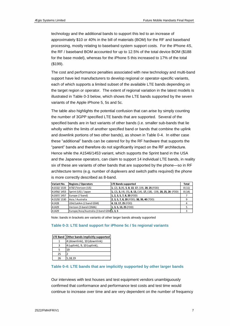
The cost and performance penalties associated with new technology and multi-band
support have led manufacturers to develop regional or operator-specific variants,
each of which supports a limited subset of the available LTE bands depending on
the target region or operator. The extent of regional variation in the latest models is
illustrated in Table 0-3 below, which shows the LTE bands supported by the seven
variants of the Apple iPhone 5, 5s and 5c.
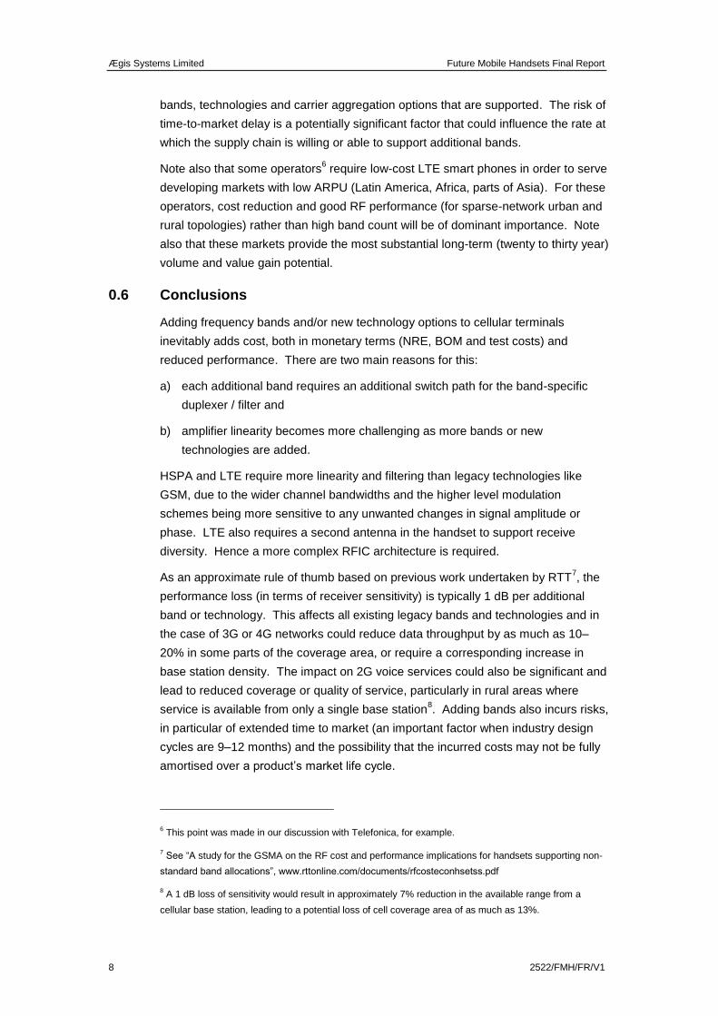
The table also highlights the potential confusion that can arise by simply counting
the number of 3GPP specified LTE bands that are supported. Several of the
specified bands are in fact variants of other bands (i.e. smaller sub-bands that lie
wholly within the limits of another specified band or bands that combine the uplink
and downlink portions of two other bands), as shown in Table 0-4. In either case
these “additional” bands can be catered for by the RF hardware that supports the
“parent” bands and therefore do not significantly impact on the RF architecture.
Hence while the A1546/1453 variant, which supports the Sprint band in the USA
and the Japanese operators, can claim to support 14 individual LTE bands, in reality
six of these are variants of other bands that are supported by the phone—so in RF
architecture terms (e.g. number of duplexers and switch paths required) the phone
is more correctly described as 8-band.
Note: bands in brackets are variants of other larger bands already supported
Table 0-3: LTE band support for iPhone 5c / 5s regional variants
Table 0-4: LTE bands that are implicitly supported by other larger bands
Our interviews with test houses and test equipment vendors unambiguously
confirmed that conformance and performance test costs and test time would
continue to increase over time and are very dependent on the number of frequency
Variant No. Regions / Operators LTE Bands supported Total
A1532/ 1533 AT&T/Verizon (US) 1, (2), 3,(4), 5, 8, 13, 17, (19), 20, 25 (FDD) 8 (11)
A1456/ 1453 Sprint (US) / Japan 1, (2), 3, (4), (5), 8, 13, (14), 17, (18), (19), 20, 25, 26 (FDD) 8 (14)
A1507/ 1457 Europe (7 band) 1, 2, 3, 5, 7, 8, 20 (FDD) 7
A1529/ 1530 Asia / Australia 2, 3, 5, 7, 8, 20 (FDD); 38, 39, 40 (TDD) 9
A1428 USA/LatAm (2 band GSM) 4, 13, 17, 25 (FDD) 4
A1429 Verizon (5 band CDMA) 1, 3, 5, 13, 25 (FDD) 5
A1429 Europe/Asia/Australia (3 band GSM)1, 3, 5 3
LTE Band Other bands implicitly supported
1 4 (downlink), 10 (downlink)
3 4 (uplink), 9, 10 (uplink),
5 19
25 2
26 5,18,19
Ægis Systems Limited Future Mobile Handsets Final Report
8 2522/FMH/FR/V1
bands, technologies and carrier aggregation options that are supported. The risk of
time-to-market delay is a potentially significant factor that could influence the rate at
which the supply chain is willing or able to support additional bands.
Note also that some operators6 require low-cost LTE smart phones in order to serve
developing markets with low ARPU (Latin America, Africa, parts of Asia). For these
operators, cost reduction and good RF performance (for sparse-network urban and
rural topologies) rather than high band count will be of dominant importance. Note
also that these markets provide the most substantial long-term (twenty to thirty year)
volume and value gain potential.
0.6 Conclusions
Adding frequency bands and/or new technology options to cellular terminals
inevitably adds cost, both in monetary terms (NRE, BOM and test costs) and
reduced performance. There are two main reasons for this:
a) each additional band requires an additional switch path for the band-specific
duplexer / filter and
b) amplifier linearity becomes more challenging as more bands or new
technologies are added.
HSPA and LTE require more linearity and filtering than legacy technologies like
GSM, due to the wider channel bandwidths and the higher level modulation
schemes being more sensitive to any unwanted changes in signal amplitude or
phase. LTE also requires a second antenna in the handset to support receive
diversity. Hence a more complex RFIC architecture is required.
As an approximate rule of thumb based on previous work undertaken by RTT7, the
performance loss (in terms of receiver sensitivity) is typically 1 dB per additional
band or technology. This affects all existing legacy bands and technologies and in
the case of 3G or 4G networks could reduce data throughput by as much as 10–
20% in some parts of the coverage area, or require a corresponding increase in
base station density. The impact on 2G voice services could also be significant and
lead to reduced coverage or quality of service, particularly in rural areas where
service is available from only a single base station8. Adding bands also incurs risks,
in particular of extended time to market (an important factor when industry design
cycles are 9–12 months) and the possibility that the incurred costs may not be fully
amortised over a product’s market life cycle.
6 This point was made in our discussion with Telefonica, for example.
7 See “A study for the GSMA on the RF cost and performance implications for handsets supporting non-
standard band allocations”, www.rttonline.com/documents/rfcosteconhsetss.pdf
8 A 1 dB loss of sensitivity would result in approximately 7% reduction in the available range from a
cellular base station, leading to a potential loss of cell coverage area of as much as 13%.
Ægis Systems Limited Future Mobile Handsets Final Report
2522/FMH/FR/V1 9
From a technical perspective some bands are more difficult to implement than
others, due, for example, to having a wide operational bandwidth or being directly
adjacent to bands used by other services that are particularly sensitive to
interference—both of which make filter realisation more challenging. These
differences are partially offset in practice by relaxed conformance specifications but
still result in a performance loss. Even an apparently easy band addition, such as
the potential extension of the 2 GHz band (LTE Band 1) into the neighbouring MSS
band, will result in an increase in operational bandwidth which will compromise the
performance of the front-end filtering9.
The need for additional bands has to date largely been driven by the need to
support emerging new technologies that cannot be accommodated in existing bands
because these are fully utilised by existing technologies. For example, the 2 GHz
band was required to support 3G services and more recently the 800 MHz and
2600 MHz bands were required to support the widespread launch of 4G LTE
services. Our own view, supported by discussion with operators, is that there is
likely to be less enthusiasm for adding further bands where these do not bring
specific technology and consumer experience10
enhancements, though a likely
exception should be the adoption of 700 MHz in Europe where the additional
capacity combined with attractive coverage and the near-global availability of the
band are likely to outweigh the cost and performance penalties incurred in other
bands.
In terms of the short to medium term (5 years), our research has largely confirmed
that both operators and RF vendors are focussing on a limited set of “core” bands,
comprising the legacy 2G and 3G bands, the more recently released digital dividend
bands below 1 GHz and additional capacity bands above 2 GHz, notably 2.6 GHz
and (to a more limited extent) 2.3 GHz. Although the operator community has been
pressing for additional bands to be released (e.g. around 1.4 GHz and 2.8 GHz)
there appears to be little or no current interest in such developments among the RF
device community. Similarly, there appears to be little interest currently in
supporting the 3.5 GHz band (3400–3600 MHz) in mainstream smartphone devices,
with current interest focussing on dongles and Wi-Fi router devices.
Rather than focussing on more bands (beyond those already identified for IMT), the
RF industry appears to be more engaged in facilitating technology enhancements
such as MIMO and carrier aggregation, and in further extending new standards
across the existing legacy bands. This reflects a widely held view that simply
9 The operational bandwidth will be increased from 3.1% to 4.6%. At 2 x 90 MHz, the expanded 2 GHz
band would be marginally harder than the 2 x 30 MHz bands at 700 MHz (which have an operational
bandwidth of 4.2%), which is not impossible but difficult enough to impose a performance loss on existing
Band 1 operator customers. Note that the benefits of the new band accrue to the new owner of the band,
the performance costs are projected on the existing incumbents.
10 This point was made in our discussion with Everything Everywhere, for example.
Ægis Systems Limited Future Mobile Handsets Final Report
10 2522/FMH/FR/V1
adding more bands to a handset does not in itself make the device more attractive
to the consumer, but adding technology enhancements will increase the appeal.
There is considerable uncertainty over what may happen in the longer term as this
largely depends on developments in relation to tunable antennas and other
frequency-dependent RF components or the development of new materials. Some
stakeholders are optimistic, suggesting the tunable devices required to provide a
fully flexible RF front end could be available as soon as 2017, whereas others
suggest these may never be realised in a way that meets progressively more
onerous performance and cost expectations. Our own view is that such
developments are unlikely to have a significant impact on handset RF design over at
least the next decade.
Whatever happens, it seems unlikely that there will be any significant move away
from the current focus on a limited number of regional core bands, although we
expect there to be a modest increase in the number of these bands over time (e.g.
with the release of 600 MHz in the US and 700 MHz in Europe).
Ægis Systems Limited Future Mobile Handsets Final Report
2522/FMH/FR/V1 11
1 INTRODUCTION
This report describes the findings of a study carried out for Ofcom by Aegis Systems
and RTT Programmes, addressing the key factors affecting multi-band support in
future cellular handset devices. Of particular interest is the likely relationship
between the number of frequency bands supported and the RF cost and
performance of a user device over the next ten to fifteen years.
Much has been said recently about the enormous growth in mobile data traffic and
the need for additional radio spectrum to support this growth. However, simply
adding more spectrum bandwidth in itself will not provide the necessary increase in
capacity required to support future data traffic levels. This can only be met by the
deployment of new technologies such as the latest 4th generation (4G) LTE
standards, which provide a significant improvement in spectrum efficiency over
legacy 2G and 3G standards. In the absence of technology evolution, adding
additional spectrum could even be counter-productive, as adding new frequency
bands to mobile devices can have an adverse effect on the performance of existing
bands, offsetting much of the gain provided by the new bands.
The main benefit of adding new bands to mobile handsets in the current market is
therefore to facilitate migration to more efficient 4G standards, rather than provision
of additional capacity per se. This is particularly the case for the recently released
800 MHz and 2600 MHz bands, without which three of the UK’s four operators were
unable to launch 4G services, due to the lack of spare capacity in their existing 2G
and 3G spectrum holdings. Similarly, the launch of 3G services a decade ago
depended on release of new spectrum in the 2 GHz band.
The value of such bands and the importance of their inclusion in the portfolio of
bands supported by mainstream cellular handsets is therefore enhanced when the
bands are directly associated with the launch of a new cellular technology. This is in
part because of the significant gain in network capacity that can be realised with each
new technology generation, but also because the new technology also provides
significant consumer value, in terms of new features and improved performance.
Conversely, once spectrum already exists to support a new technology, the value of
additional spectrum diminishes. This is partly because the additional capacity
provided by the new spectrum tends to be at least partially offset by a loss of
capacity resulting from performance degradation in existing bands when the new
spectrum is incorporated into mobile devices, and partly because spectrum in
existing bands can be progressively migrated to the new technology, as has recently
been the case with migration of 900 MHz from 2G to 3G. For this reason there is
likely to be less incentive for suppliers to integrate new bands into existing product
lines where these are not a specific prerequisite to support a particular technology.
One exception may be where an existing band can be extended without impacting
significantly on the existing use of the band. Currently the only instance where this
Ægis Systems Limited Future Mobile Handsets Final Report
12 2522/FMH/FR/V1
appears to be feasible is the potential extension of the 2 GHz band (LTE Band 1) into
the neighbouring MSS band, which shares the same duplex characteristics although
even this projects potential performance loss onto devices that have to be
redesigned to accommodate the additional operational bandwidth (see Section 3.5
for a more detailed discussion). Another is adoption of 700 MHz in Europe where the
additional capacity combined with attractive coverage and the near-global availability
of the band is likely to outweigh the cost and performance penalties incurred in other
bands.
The above discussion should not be taken as implying that there is no requirement
for additional mobile bands in the future. On the contrary, as mobile technology
continues to evolve it is likely that additional bands will be required to support new
technologies, just as the 2 GHz and 800 MHz bands were required to support 3G and
4G respectively. New bands may also have a role supporting specialist applications
like fixed wireless broadband, machine-to-machine communication or wireless
dongles, where multi-band support is less important due to the less mobile nature of
the application.
It does, however, mean that there is unlikely to be a significant change in the rate of
take-up of new bands in mainstream smart phones where the small form factor
makes the addition of new bands particularly problematic in terms of complexity, cost
and performance. Instead, development effort is more likely to focus on maximising
the capability of existing bands, by extending LTE support to an increasing number of
existing 2G / 3G bands and deploying other performance enhancement techniques
such as MIMO and carrier aggregation. Even these techniques can incur a penalty in
terms of cost and the performance of legacy services (such as GSM); however, as
technology migration progresses this is likely to be outweighed by the increased
overall capacity and spectrum efficiency that they provide.
In the remainder of this report, we first provide an overview of the evolution of global
cellular frequency bands and multi-band handset support. We then go on to consider
the technical challenges associated with supporting new frequency bands and the
associated costs and benefits of such support. Finally, we present our conclusions
regarding the likely development of multi-band handset support over the next
decade.
Ægis Systems Limited Future Mobile Handsets Final Report
2522/FMH/FR/V1 13
2 TRENDS IN MULTI-BAND SUPPORT
2.1 Evolution of cellular frequency allocations
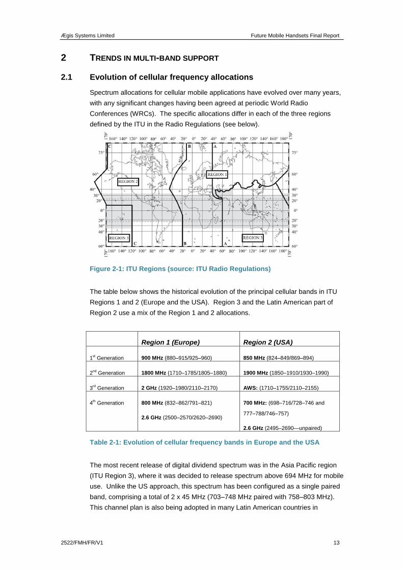
Spectrum allocations for cellular mobile applications have evolved over many years,
with any significant changes having been agreed at periodic World Radio
Conferences (WRCs). The specific allocations differ in each of the three regions
defined by the ITU in the Radio Regulations (see below).
Figure 2-1: ITU Regions (source: ITU Radio Regulations)
The table below shows the historical evolution of the principal cellular bands in ITU
Regions 1 and 2 (Europe and the USA). Region 3 and the Latin American part of
Region 2 use a mix of the Region 1 and 2 allocations.
Region 1 (Europe) Region 2 (USA)
1st Generation 900 MHz (880–915/925–960) 850 MHz (824–849/869–894)
2nd
Generation 1800 MHz (1710–1785/1805–1880) 1900 MHz (1850–1910/1930–1990)
3rd Generation 2 GHz (1920–1980/2110–2170) AWS: (1710–1755/2110–2155)
4th Generation 800 MHz (832–862/791–821)
2.6 GHz (2500–2570/2620–2690)
700 MHz: (698–716/728–746 and
777–788/746–757)
2.6 GHz (2495–2690—unpaired)
Table 2-1: Evolution of cellular frequency bands in Europe and the USA
The most recent release of digital dividend spectrum was in the Asia Pacific region
(ITU Region 3), where it was decided to release spectrum above 694 MHz for mobile
use. Unlike the US approach, this spectrum has been configured as a single paired
band, comprising a total of 2 x 45 MHz (703–748 MHz paired with 758–803 MHz).
This channel plan is also being adopted in many Latin American countries in
Ægis Systems Limited Future Mobile Handsets Final Report
14 2522/FMH/FR/V1
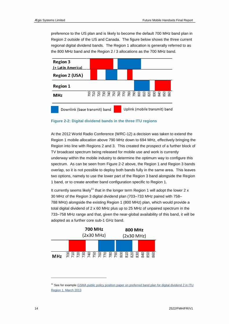
preference to the US plan and is likely to become the default 700 MHz band plan in
Region 2 outside of the US and Canada. The figure below shows the three current
regional digital dividend bands. The Region 1 allocation is generally referred to as
the 800 MHz band and the Region 2 / 3 allocations as the 700 MHz band.
Figure 2-2: Digital dividend bands in the three ITU regions
At the 2012 World Radio Conference (WRC-12) a decision was taken to extend the
Region 1 mobile allocation above 790 MHz down to 694 MHz, effectively bringing the
Region into line with Regions 2 and 3. This created the prospect of a further block of
TV broadcast spectrum being released for mobile use and work is currently
underway within the mobile industry to determine the optimum way to configure this
spectrum. As can be seen from Figure 2-2 above, the Region 1 and Region 3 bands
overlap, so it is not possible to deploy both bands fully in the same area. This leaves
two options, namely to use the lower part of the Region 3 band alongside the Region
1 band, or to create another band configuration specific to Region 1.
It currently seems likely11
that in the longer term Region 1 will adopt the lower 2 x
30 MHz of the Region 3 digital dividend plan (703–733 MHz paired with 758–
788 MHz) alongside the existing Region 1 (800 MHz) plan, which would provide a
total digital dividend of 2 x 60 MHz plus up to 25 MHz of unpaired spectrum in the
733–758 MHz range and that, given the near-global availability of this band, it will be
adopted as a further core sub-1 GHz band.
11 See for example GSMA public policy position paper on preferred band plan for digital dividend 2 in ITU
Region 1, March 2013
Ægis Systems Limited Future Mobile Handsets Final Report
2522/FMH/FR/V1 15
Figure 2-3: Probable long-term digital dividend spectrum in Region 1
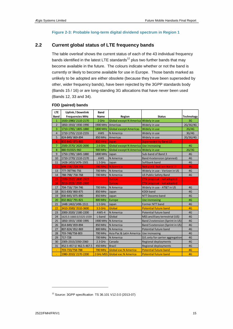
2.2 Current global status of LTE frequency bands
The table overleaf shows the current status of each of the 43 individual frequency
bands identified in the latest LTE standards12
plus two further bands that may
become available in the future. The colours indicate whether or not the band is
currently or likely to become available for use in Europe. Those bands marked as
unlikely to be adopted are either obsolete (because they have been superseded by
other, wider frequency bands), have been rejected by the 3GPP standards body
(Bands 15 / 16) or are long-standing 3G allocations that have never been used
(Bands 12, 33 and 34).
FDD (paired) bands
12 Source: 3GPP specification TS 36.101 V12.0.0 (2013-07)
1 1920-1980/ 2110-2170 2 GHz Global except N America Widely in use 3G
2 1850-1910/ 1930-1990 1900 MHz Americas Widely in use 2G/3G/4G
3 1710-1785/ 1805-1880 1800 MHz Global except Americas Widely in use 2G/4G
4 1710-1755/ 2110-2155 AWS N America Widely in use 3G/4G
5 824-849/ 869-894 850 MHz Americas Widely in use 2G/3G/4G
6 830-840/ 875-885 850 MHz Japan Superseded by Band 19 -
7 2500-2570/ 2620-2690 2.6 GHz Global except N America Use increasing 4G
8 880-915925-960 900 MHz Global except N America Widely in use 2G/3G
9 1750-1785/ 1845-1880 1800 MHz Japan Sub-band of Band 3 4G
10 1710-1770/ 2110-2170 AWS N America Band 4 extension (planned) 4G
11 1428-1453/1476-1501 1.5 GHz Japan Softbank band 4G
12 698-716/ 728-746 700 MHz N America Not used - but see Band 17 4G
13 777-787746-756 700 MHz N America Widely in use - Verizon in US 4G
14 788-798/ 758-768 700 MHz N America US Public Safety Band 4G
15 1900-1920/ 2600-2620 - Europe ETSI proposal - not adopted -
16 2010-2025/ 2585-2600 - Europe ETSI proposal - not adopted -
17 704-716/ 734-746 700 MHz N America Widely in use - AT&T in US 4G
18 815-830/ 860-875 850 MHz Japan KDDI band 4G
19 830-845/ 875-890 850 MHz Japan NTT Docomo band 4G
20 832-862/ 791-821 800 MHz Europe Use increasing 4G
21 1448-1463/1496-1511 1.5 GHz Japan Former NTT band 4G
22 3410-3500/ 3510-3600 3.5 GHz Global Potential future band 4G
23 2000-2020/ 2180-2200 AWS-4 N America Potential future band 4G
24 1625.5-1660.5/1525-1559 L-band Global MSS ancilliary terrestrial (US) 4G
25 1850-1915/ 1930-1995 1900 MHz N America Band 2 extension (Sprint in US) 4G
26 814-849/ 859-894 850 MHz N America Band 5 extension (Sprint in US) 4G
27 807-824/ 852-869 800 MHz N America Potential future band 4G
28 703-748/758-803 700 MHz Asia Pac & Latin America Use increasing 4G
29 717-728 700 MHz N America D/L only for carrier aggregation 4G
30 2305-2315/2350-2360 2.3 GHz Canada Regional deployments 4G
31 452.5-457.5/ 462.5-467.5 450 MHz Brazil Regional deployments 4G
- 703-733/758-788 700 MHz Global exc N America Potential future band 4G
- 1980-2010/ 2170-2200 2 GHz MSS Global exc N America Potential future band 4G
LTE
Band TechnologyRegion Status
Band
Name
Uplink / Downlink
Frequencies MHz
Ægis Systems Limited Future Mobile Handsets Final Report
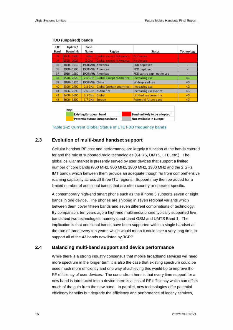
16 2522/FMH/FR/V1
TDD (unpaired) bands
Table 2-2: Current Global Status of LTE FDD frequency bands
2.3 Evolution of multi-band handset support
Cellular handset RF cost and performance are largely a function of the bands catered
for and the mix of supported radio technologies (GPRS, UMTS, LTE, etc.). The
global cellular market is presently served by user devices that support a limited
number of core bands (850 MHz, 900 MHz, 1800 MHz, 1900 MHz and the 2 GHz
IMT band), which between them provide an adequate though far from comprehensive
roaming capability across all three ITU regions. Support may then be added for a
limited number of additional bands that are often country or operator specific.
A contemporary high-end smart phone such as the iPhone 5 supports seven or eight
bands in one device. The phones are shipped in seven regional variants which
between them cover fifteen bands and seven different combinations of technology.
By comparison, ten years ago a high-end multimedia phone typically supported five
bands and two technologies, namely quad-band GSM and UMTS Band 1. The
implication is that additional bands have been supported within a single handset at
the rate of three every ten years, which would mean it could take a very long time to
support all of the 43 bands now listed by 3GPP.
2.4 Balancing multi-band support and device performance
While there is a strong industry consensus that mobile broadband services will need
more spectrum in the longer term it is also the case that existing spectrum could be
used much more efficiently and one way of achieving this would be to improve the
RF efficiency of user devices. The conundrum here is that every time support for a
new band is introduced into a device there is a loss of RF efficiency which can offset
much of the gain from the new band. In parallel, new technologies offer potential
efficiency benefits but degrade the efficiency and performance of legacy services,
33 1900 - 1920 2 GHz Global except N America Not in use -
34 2010 - 2025 2 GHz Global except N America Not in use -
35 1850 - 1910 1900 MHz Americas FDD deployed -
36 1930 - 1990 1900 MHz Americas FDD deployed -
37 1910 - 1930 1900 MHz Americas FDD centre gap - not in use -
38 2570 - 2620 2.6 GHz Global except N America Increasing use 4G
39 1880 - 1920 1900 MHz China Widespread use 4G
40 2300 - 2400 2.3 GHz Global (certain countries) Increasing use 4G
41 2496 - 2690 2.6 GHz N America Increasing use (Sprint) 4G
42 3400 - 3600 3.5 GHz Global Limited use currently 4G
43 3600 - 3800 3.7 GHz Europe Potential future band 4G
LTE
Band
Uplink /
Downlink
Band
Name TechnologyRegion Status
Existing European band Band unlikely to be adopted
Potential future European band Not available in Europe
Key:
Ægis Systems Limited Future Mobile Handsets Final Report
2522/FMH/FR/V1 17
which continue to play an important role—voice and messaging services, for
example.
Ægis Systems Limited Future Mobile Handsets Final Report
18 2522/FMH/FR/V1
3 TECHNICAL CHALLENGES ASSOCIATED WITH SUPPORTING NEW
FREQUENCY BANDS
As noted in the introduction to the report, the addition of new frequency bands and/or
technologies has an impact on the performance available from existing bands and
technologies where these are deployed in the same device. Bands that are either
technically easier to service, do not impose a performance loss on other bands13
and
are commercially more attractive will therefore continue to be prioritised by the RF
component supply chain, to the possible detriment of support for other more
challenging or less popular bands.
A further factor that will have a direct bearing on handset cost and complexity is the
introduction in the more recent LTE standards of support for carrier aggregation, i.e.
the transmission of information across two or more radio channels simultaneously to
provide a higher transmission speed. At its simplest, carrier aggregation may simply
involve combining two carriers within the same band (as already happens, for
example, with dual-carrier HSPA), but the latest standards also cater for aggregation
across different combinations of bands, which can increase complexity significantly.
In the following sections we first provide a brief introduction to the RF architecture
currently deployed in cellular phones and consider some of the technical challenges
that are likely to have a bearing on future frequency band support.
3.1 Frequency limitations of cellular phone RF architecture
3.1.1 Introduction
In this section we present a brief overview of how the radio frequency (RF) part of a
cellular handset operates and the key components that have a bearing on frequency
band support.
Most phones operate in frequency-division duplex mode (FDD), where interference
within the phone (due principally to its own transmitter), is managed by having
separate upper and lower duplex sub-bands. Figure 3.1 below shows a schematic
diagram of the partitioning of a typical mobile handset showing the functional
difference between RF front end and baseband in a frequency division duplex (FDD)
transceiver. The RF front-end will consist of a number of RFICs or modules and a
number of discrete components. The figure indicates the degree of frequency
dependence of the main components: those in red are band specific (separate
component required for each band), those in orange are frequency dependent but
are able to cover more than one band and those in green are not frequency
dependent (can be shared across all bands).
13 Notably those bands that are effectively sub-bands falling entirely within other wider bands, e.g. the
Japanese 1800 MHz band.
Ægis Systems Limited Future Mobile Handsets Final Report
2522/FMH/FR/V1 19
The figure below shows a schematic diagram of a typical mobile handset RF front
end and baseband processor, based on frequency-division duplex (FDD) operation.
See Figure 3-2 for an example vendor implementation block diagram.
Figure 3-1: High-level schematic diagram of a cellular phone RF architecture
The functions of the principal RF and baseband components are described briefly
below:
RF Front end—Receiver
Antenna—receives the incoming RF signal; may be common to several
bands.
Switch—connects the antenna to the required band-specific duplexer.
Duplexer—uses filters to separate transmit energy from received signal.
Low-Noise Amplifier (LNA)—amplifies the low received signal for subsequent
down conversion and processing.
Down converter—converts RF signal to baseband to enable extraction of
encoded information.
Local Oscillator—generates and injects mixing frequency to convert RF
signal.
Low Pass Filter (LPF)—defines analogue baseband bandwidth prior to
conversion (often active, providing gain).
Ægis Systems Limited Future Mobile Handsets Final Report
20 2522/FMH/FR/V1
Analogue to Digital Converter (ADC)—converts the baseband analogue
signal to its digital equivalent for subsequent processing.
Digital Signal Processing (DSP)—recovers the source coded data (voice,
video etc.).
RF Front end—Transmitter
DSP—source codes and channel codes the data to be transmitted.
Digital to Analogue Converter (DAC)—converts the digital source-coded data
to a baseband analogue signal that can be modulated onto the RF carrier.
Modulator—generates the RF carrier frequency modulated with the
baseband signal.
Voltage controlled oscillator (VCO) and synthesiser—generates the carrier
frequency to be modulated (frequency can be selected within a given band)
by Phase Locked Loop (PLL) programming.
Power Amplifier (PA) and driver—amplifies the modulated carrier to the
required transmission power.
Duplexer—uses filters to separate transmit energy from received signal.
Each component in the RF front end has an associated input and output impedance
which must be closely matched to that of the adjacent components to minimise any
power losses. As impedance is frequency dependent, additional tuning elements
may be required to ensure a reasonable match is obtained over the desired
frequency range. For example, a poorly matched power amplifier will have a high
percentage of its generated power reflected back which in severe cases can result in
catastrophic failure.
Protection from other users or radio systems is achieved by having a frequency
separation known as the guard band. It is the job of the various filters in the phone to
provide sufficient attenuation of unwanted signals (either inside or outside the phone)
while minimising the impact on the wanted signal.
In a TDD transceiver the duplex filters in the front end are replaced by an additional
RF switch that alternates the antenna connection between the transmitter and
receiver, but the bandwidth still needs to be defined by a receiver input filter and a
transmit output filter as the receiver needs to be protected from out-of-band
unwanted signal energy (a band-pass filter) and the transmit path has to be filtered to
prevent out-of-band noise and signals being transmitted. TDD is promoted in
technical literature as being simpler to implement. In practice, though there may be
some relaxation of frequency domain filtering, there will be an associated cost in the
time domain which typically results in inter symbol interference (ISI). This can be
problematic for larger cell radius, uncoordinated and non-synchronised TDD
networks. ISI has the effect of reducing overall network performance (e.g. lower data
rates, reduced coverage).
Ægis Systems Limited Future Mobile Handsets Final Report
2522/FMH/FR/V1 21
In the following sections we consider the frequency limitations of each of the
identified components and the implications for multi-band devices.
3.1.2 Antennas
The antenna is essentially a passive device which radiates the transmitted signal and
routes incoming signals from the network to the RF front end. To operate efficiently,
a phone antenna should ideally be at least a quarter of a wavelength long at the
frequency of operation. This is particularly challenging in small form-factor devices at
lower frequencies—e.g. at 700 MHz a quarter wavelength is approximately 10 cm. In
addition, to exploit fully the potential of MIMO techniques to enhance data speed and
network capacity, it is necessary to deploy multiple antenna elements within the
phone, which also need to be separated by a similar (quarter wavelength) distance,
and even basic LTE user devices are required to support receive diversity (i.e. use
two separate receive antennas).
The efficiency of an antenna decreases as bandwidth increases, presenting a
particular challenge for multi-band devices where there is insufficient space to
provide a separate antenna for each band. Multi-band antennas can be achieved by
building multi-resonant antenna structures and/or having antennas that are
electrically short in lower bands (i.e. less than the required quarter wavelength), with
the associated mismatch being compensated through adaptive matching (variable
capacitance). The penalty for this is that less “real” antenna is available for capturing
the transmitted signal. These broader-band antennas also become progressively
more sensitive to hand capacitance effects, which makes performance sensitive to
how the user holds the device.
Multi-band antennas tend to have limited bandwidth below 1 GHz. It is therefore
difficult to extend beyond the 850 / 900 MHz bands with a single antenna, so a
separate antenna is generally required to cover 700 or 800 MHz, although there have
been some recent attempts to achieve wider bandwidths with tunable antennas (see
Section 3.6.1). Hence some recent phones deploy a separate antenna for the lowest
frequency band (e.g. 700 MHz in the US) and a second multi-band antenna to
support the higher frequency bands. However, even this raises the issue of whether
to use an operator-specific antenna for the lower band to optimise performance, or a
wider-bandwidth antenna which would support all operators or even multiple sub-
1 GHz bands (e.g. 700 and 800 MHz) at the expense of a potentially significant loss
of efficiency.
3.1.3 Switches
RF switches are required to route signals between a multi-band antenna and the
various band-specific duplexers. Each duplex filter is connected by a unique switch
path which introduces insertion loss (signal attenuation) and may compromise
receive and transmit linearity (the impact of the latter is discussed further in Section
3.1.5 below).
Ægis Systems Limited Future Mobile Handsets Final Report
22 2522/FMH/FR/V1
The RF switches deployed in mobile phones are single-pole multi-throw (SPMT)
devices, where the single pole refers to the single interface with the antenna and the
multi-throw refers to the number of band-specific duplexers that the switch can
connect to. Switch technology has advanced considerably in recent years, with the
introduction of relatively exotic material combinations such as silicon on sapphire
(SOS) to improve performance. The latest devices are capable of supporting as
many as 16 outputs (i.e. single pole, 16 throw), which in theory could support up to
16 bands. However, as the switch throw count increases, the performance inevitably
degrades due to increased insertion loss and inter-switch matching becomes
progressively more compromised—again the performance is degraded. Additionally,
the control line structure (the circuits that provide the DC voltages necessary to
operate the individual RF switches) becomes more complex.
3.1.4 Filters and duplexers
Filters play an important role in supporting mobile-phone operation and are deployed
at various stages in the RF front end and baseband processing. The RF filters
deployed in phones are acoustic filters, which provide good performance in a
compact space but have significant bandwidth limitations which play a major role in
determining which frequency bands can be supported in a mobile device.
In particular, the duplex filter which separates the incoming receive signal from the
outgoing transmit signal in an FDD-based device is constrained to a maximum
operational bandwidth (for transmit or receive) of the order of 4 per cent of the band
centre frequency if reasonable performance is to be achieved. Any extension
beyond this limit will result in progressive performance degradation, mainly
manifested in additional signal attenuation. For this reason the recently agreed Asia
Pacific region 700 MHz band, which comprises 2 x 45 MHz (6% of the centre
frequency) requires two separate duplexers to be supported in full. Duplexer
performance constraints also dictate the separation required between the uplink and
downlink sub-bands (duplex gap), which in practice must be at least of the order of
1% or more of the centre frequency.
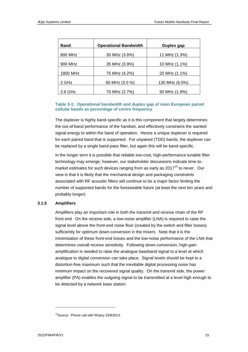
These limitations constrain the scope for extending existing bands (there are also
other factors—see Section 3.5), since most bands are already close to these limits,
as the table below illustrates. The 1800 MHz band for example is challenging
because of the higher operational bandwidth percentage and the low duplex gap
percentage. Introducing new technologies into the 1800 MHz band, such as LTE,
requires careful design optimisation to ensure filter flatness is maintained across all
of the available bandwidth with sufficient roll off at the band edge to protect adjacent
services.
Ægis Systems Limited Future Mobile Handsets Final Report
2522/FMH/FR/V1 23
Band Operational Bandwidth Duplex gap
800 MHz 30 MHz (3.6%) 11 MHz (1.3%)
900 MHz 35 MHz (3.9%) 10 MHz (1.1%)
1800 MHz 75 MHz (4.2%) 20 MHz (1.1%)
2 GHz 60 MHz (3.0 %) 130 MHz (6.5%)
2.6 GHz 70 MHz (2.7%) 50 MHz (1.9%)
Table 3-1: Operational bandwidth and duplex gap of main European paired cellular bands as percentage of centre frequency
The duplexer is highly band-specific as it is this component that largely determines
the out-of-band performance of the handset, and effectively constrains the wanted
signal energy to within the band of operation. Hence a unique duplexer is required
for each paired band that is supported. For unpaired (TDD) bands, the duplexer can
be replaced by a single band-pass filter, but again this will be band-specific.
In the longer term it is possible that reliable low-cost, high-performance tunable filter
technology may emerge; however, our stakeholder discussions indicate time-to-
market estimates for such devices ranging from as early as 201714
to never. Our
view is that it is likely that the mechanical design and packaging constraints
associated with RF acoustic filters will continue to be a major factor limiting the
number of supported bands for the foreseeable future (at least the next ten years and
probably longer).
3.1.5 Amplifiers
Amplifiers play an important role in both the transmit and receive chain of the RF
front end. On the receive side, a low-noise amplifier (LNA) is required to raise the
signal level above the front-end noise floor (created by the switch and filter losses)
sufficiently for optimum down-conversion in the mixers. Note that it is the
minimisation of these front-end losses and the low-noise performance of the LNA that
determines overall receive sensitivity. Following down-conversion, high-gain
amplification is needed to raise the analogue baseband signal to a level at which
analogue to digital conversion can take place. Signal levels should be kept to a
distortion-free maximum such that the inevitable digital processing noise has
minimum impact on the recovered signal quality. On the transmit side, the power
amplifier (PA) enables the outgoing signal to be transmitted at a level high enough to
be detected by a network base station.
14Source: Phone call with Wispry 23/8/2013
Ægis Systems Limited Future Mobile Handsets Final Report
24 2522/FMH/FR/V1
For both the LNA and PA it is vital that the amplification process introduces minimal
distortion to the signal, otherwise vital information in the signal may be lost. 3G and
4G systems require substantially higher linearity than 2G systems, predominantly
due to the use of higher-order modulation but also as a consequence of the way the
different types of traffic are multiplexed onto each channel. Linearity in this context
means that the relationship between the input and output signals should have
minimal variation with frequency or signal level.
In 3G and 4G radio systems, transmitted information is modulated onto the radio
carrier using a combination of phase and amplitude modulation. This means that all
devices in the receive and transmit path require sufficient linearity to ensure this
phase and amplitude information is preserved. In practice some non-linearity is
inevitable and this will increase in line with the operational bandwidth of the amplifier,
effectively placing a limit on the bandwidth that can be supported by a single LNA or
PA device when handling complex wideband signals.
The bandwidth that can be supported by an LNA or PA is typically sufficient to cover
a number of adjacent bands—for example, three amplifiers should be sufficient to
cover the 700–900 MHz, 1800—2100 MHz or 2300–2700 MHz ranges. In practice,
separate band-specific LNAs tend to be deployed in order to avoid the need for
additional switches or combiners after the duplexer, which would further degrade the
signal quality prior to amplification. This is not a major problem as LNAs are
relatively compact, low-cost devices.
PAs are larger and signal degradation less of an issue on the transmit side so these
are more likely to be shared between bands. PAs can be made to work across wider
frequency ranges by using a technique called envelope tracking, which improves
power efficiency but can induce additional noise in the receive path. For example,
Nujira claim their envelope-tracking technology can support three power amplifiers
simultaneously and cover up to 16 FDD and TDD bands between 200 and
2700 MHz, supporting channel bandwidths up to 20 MHz (and potentially wider for
carrier aggregation).
However, the same basic trade off applies for PAs as for antennas, in that linearity
becomes progressively harder to achieve as bandwidth increases. PAs also become
progressively less efficient and noisier at higher frequencies.
3.1.6 RFIC and Transceiver Module configuration constraints
There are other factors that constrain additional band/technology support and that
have an impact at an early stage of the design cycle for example the number of pin
outs/ports on the transceiver module and the pin counts on individual RFICs.
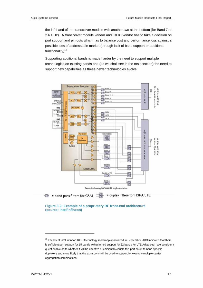
The example below from Intel/Infineon shows the complexity implicit in supporting
three technologies (GSM, HSPA and LTE including LTE receive diversity) across six
bands.
More ports consume space, add complexity and cost and introduce port to port
isolation issues. In this example this device has 21 ports (connection points) along
Ægis Systems Limited Future Mobile Handsets Final Report
2522/FMH/FR/V1 25
the left hand of the transceiver module with another two at the bottom (for Band 7 at
2.6 GHz). A transceiver module vendor and RFIC vendor has to take a decision on
port support and pin outs which has to balance cost and performance loss against a
possible loss of addressable market (through lack of band support or additional
functionality)15
Supporting additional bands is made harder by the need to support multiple
technologies on existing bands and (as we shall see in the next section) the need to
support new capabilities as these newer technologies evolve.
Figure 3-2: Example of a proprietary RF front-end architecture (source: Intel/Infineon)
15 The latest Intel Infineon RFIC technology road map announced in September 2013 indicates that there
is sufficient port support for 15 bands with planned support for 22 bands for LTE Advanced. We consider it
questionable as to whether it will be effective or efficient to couple this port count to band specific
duplexers and more likely that the extra ports will be used to support for example multiple carrier
aggregation combinations.
Ægis Systems Limited Future Mobile Handsets Final Report
26 2522/FMH/FR/V1
In the above schematic the transceiver module comprises a number of RFICs and
baseband ICs assembled (probably at chip level) within the package. The PAs and
RF filters lie outside the module. Note that the term RF front-end is subject to a
number of possible definitions. One definition is to use the term to describe just the
discrete RF components between the transceiver module and the antenna. However
most RF design engineers would consider the RF front-end as being all the
components and functions between the ADC/DAC and the antenna.
3.1.7 Baseband processing
Note that interaction between the RF front-end and the baseband processing can
have a significant effect on a phone’s performance. For example, there are an
increasing number of RF functions that require information to be exchanged between
the baseband processor and RF front end. Examples include transmitter power
control and adaptive antenna matching, which require control signals to be applied to
specific RF components in response to information extracted by the baseband
processing. The close proximity of these control lines, both physically and in
frequency / processing speed terms (digital processors typically work at 1 GHz or
more) means considerable design and development effort must be invested to
minimise the risk of mutual interference.
3.1.8 Conclusions
The main constraint on expanding the number of bands in a mobile device is the
need for an additional filter or duplexer to support the new band (which adds cost and
complexity) and the need for additional switching and broader bandwidth
amplification, both of which degrade performance. The typical performance
degradation resulting from the addition of one further band to a handset is of the
order of 1 dB, based on earlier work by RTT.
This performance loss may seem insignificant, but the impact of this for an LTE
network would be to reduce the typical data rate for users by as much as 10–20%,
particularly towards the edge of the coverage area, or alternatively to require a
corresponding increase in the number of network base stations. Note also that the
performance loss would apply to all existing bands; hence the loss of throughput in
these bands needs to be offset against the gain in capacity arising from the new
band.
It is helpful to consider what happens when a decision is made to move from a lower
band count to higher band count phone.
Firstly, the impact on front-end components needs to be assessed. There are a
number of frequency dependent components in the front end including:
passive devices such as acoustic filters and antennas
active devices including RF power amplifiers on the transmit path and low-
noise amplifiers on the receive path.
Ægis Systems Limited Future Mobile Handsets Final Report
2522/FMH/FR/V1 27
The active devices need matching (power matching for RF amplifiers, noise matching
for low-noise amplifiers) using discrete components (inductors, capacitors, and
resistors). The amplifiers and antennas may not have sufficient bandwidth to
accommodate the new band, in which case the mechanical layout may change.
An additional switch path will be needed. There is a physical limit (currently 16) to
the number of switch throws that can be supported on one die16
. If the additional
band cannot be accommodated then an additional switch path will be needed or a
diplexer will be needed to direct the signal to one or other switch path. This will
introduce some additional insertion loss (about a dB) and cost (about $1). The
additional loss will be imposed across all supported bands.
The design then needs to be verified for potential intermodulation products between
the new band and the existing bands in the phone.17
This includes any
intermodulation products produced by aggregating the new band with other carriers
including low-band (sub-1 GHz), mid-band (1–2 GHz) and high-band (above 2 GHz)
carriers. Although the likelihood of intermodulation can be reduced by increasing the
dynamic range of the RF receive front-end, this has the effect of increasing power
drain which reduces battery life, degrading the user experience. Alternatively
transmit power can be reduced, but this may reduce uplink data speeds.
The device will then need conformance testing, requiring the use of expensive
specialist test-house resources. Note that LTE test costs are currently of the order of
£450 per hour and that addition of LTE support increases test time per LTE band by
about 50% (100 hours becomes 150 hours18
). It is not the monetary cost which is
important (it is relatively trivial in the overall scheme of things) but the time cost and
the associated time-to-market risk (a late launch of a market-leading smart phone
can write several percentage points off an operator’s stock market valuation).
3.2 Implications of new technology requirements
3.2.1 Introduction
The relative ease or difficulty of supporting new bands in user devices is closely
coupled with the need to support new capabilities defined in the evolving 3GPP
standards. These capability requirements include:
Carrier Aggregation
MIMO
Enhanced Inter-cell Interference Co-ordination
16 Based on discussions earlier this year with Peregrine Semiconductor.
17 This can be accommodated to an extent by increasing dynamic range but tis increases power drain and
therefore degrades the consumer experience.
18 See Anite and Testime interviews.
Ægis Systems Limited Future Mobile Handsets Final Report
28 2522/FMH/FR/V1
Evolved Multi-carrier HSPA
LTE Direct Mode (terminal-to-terminal communications, currently under
consideration for public safety applications)
High Power LTE for public safety
Wi-Fi, HSPA and LTE interworking.
In parallel, there may be a need to support unidirectional services such as Evolved
Multi Media Broadcast Multicast Service (eMBMS) and associated supplementary
downlink only (SDL) channels. This further increases design and device complexity.
These new capabilities have to be combined with continuing support for legacy
standards and frequency bands.
This means that the RF front end has to be capable of supporting legacy air
interfaces including GSM and GPRS and working efficiently in bands that are being
re-farmed, for example the 900 and 1800 MHz bands in Europe and the 1900 MHz
band in the US. User devices may in future also be required to support both FDD
and TDD, for example in the 2.6 GHz band (LTE Bands 7 and 38). This is a
particular challenge in terms of avoiding interference between mobile device
transmission and reception on adjacent frequency channels (e.g. where two mobile
devices are in close proximity). A recent study for the European Commission on
FDD-TDD co-existence in the 2 GHz band concluded that the LTE-TDD interference
is very harmful to the uplink LTE-FDD received signal in the adjacent band19
.
Two particular developments that may be a particular challenge in the short to
medium term are carrier aggregation and MIMO, which we discuss below.
3.2.2 Carrier Aggregation
Carrier aggregation is an important development that has the potential to deliver
higher peak data rates and network capacity within existing bands, or to facilitate the
deployment of unpaired spectrum by aggregating this with an existing paired
frequency channel (thus increasing the capacity in the downlink direction where
demand is greatest). The technique was introduced in Release 10 of the LTE
standards and is attracting increasing interest among the operator community.
There are many ways in which carriers can theoretically be combined. The simplest
approach would be to combine two carriers in an existing frequency band, in a similar
fashion to already-deployed HSPA dual-carrier technology. However, this approach
has limited appeal since (unlike HSPA) LTE can already deploy a range of channel
bandwidths up to 20 MHz. Inter-band aggregation is attractive as it allows operators
to combine spectrum in different bands where they have licences. For example, in
the US, AT&T has recently proposed aggregating an LTE carrier in the 700 MHz
19“ Laboratory Tests on the Coexistence between 4G TDD and 3G/4G FDD in the 1900-1920 MHz Spectrum Band”,
Joint Research Centre report for the European Commission, 2012
Ægis Systems Limited Future Mobile Handsets Final Report
2522/FMH/FR/V1 29
band with a carrier in the AWS 1700/2100 MHz band or a high-band (above 2.3 GHz)
allocation with a low-band downlink-only carrier (TV channels 55 and 56 in the
700 MHz band) and/or aggregating their 700 MHz band (LTE) with 850 band
channels (HSPA).
The objective of carrier aggregation is to have two carriers or more being received
through the same receive path in the handset and possibly in the longer term two
carriers or more being transmitted though the same transmit path (the former is a
higher priority as most traffic is in the downlink direction). At network level a high/low
combination would involve a handset being camped on a macrocell on the low-band
carrier with simultaneous access to a microcell or picocell on the higher-band carrier.
A low/low combination such as the 700/850 proposal from AT&T would be more likely
to be served from the same cells.
With either of these options, the impact of carrier aggregation is to increase the peak-
to-average power ratio of the transmitted signal, which requires more linearity in the
receive and transmit path amplifiers (see Section 3.1.5). If used in the uplink, CA
may also increase the risk of intermodulation products being generated (since two
signals are being simultaneously transmitted at different frequencies), which could
compromise the performance of the both the user’s device and other nearby devices
(if the intermodulation products lie within the operational bandwidth of the affected
device).
Inter-band carrier aggregation requires duplication of the RF front end and much of
the baseband circuitry to deal independently with the two carriers (see figure below).
If a multi-band antenna is deployed, it is necessary to separate the two carrier
frequencies received by the antenna so that each can be fed to the appropriate band-
specific duplexer. This requires the addition of a diplexer, which will add further
attenuation to the received signals. The two separated carriers are then individually
down-converted to baseband and each must be fed through a separate analogue to
digital converter before being re-combined in the decoding stage.
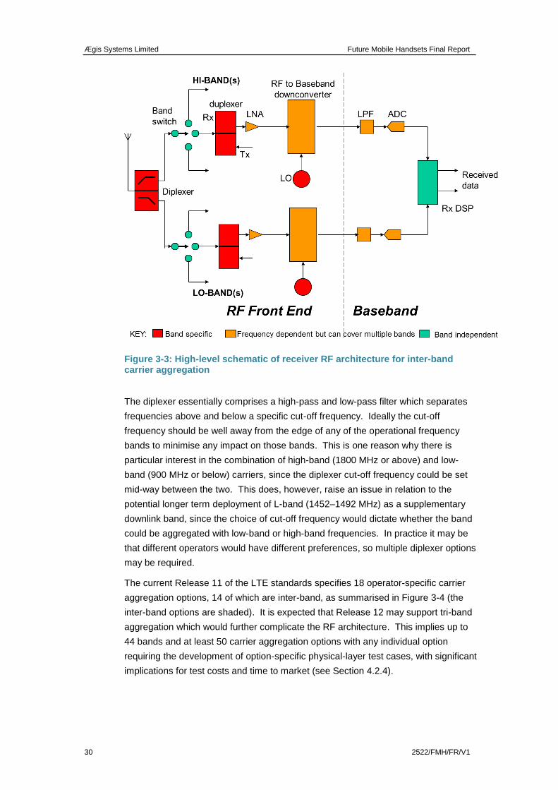
Ægis Systems Limited Future Mobile Handsets Final Report
30 2522/FMH/FR/V1
Figure 3-3: High-level schematic of receiver RF architecture for inter-band carrier aggregation
The diplexer essentially comprises a high-pass and low-pass filter which separates
frequencies above and below a specific cut-off frequency. Ideally the cut-off
frequency should be well away from the edge of any of the operational frequency
bands to minimise any impact on those bands. This is one reason why there is
particular interest in the combination of high-band (1800 MHz or above) and low-
band (900 MHz or below) carriers, since the diplexer cut-off frequency could be set
mid-way between the two. This does, however, raise an issue in relation to the
potential longer term deployment of L-band (1452–1492 MHz) as a supplementary
downlink band, since the choice of cut-off frequency would dictate whether the band
could be aggregated with low-band or high-band frequencies. In practice it may be
that different operators would have different preferences, so multiple diplexer options
may be required.
The current Release 11 of the LTE standards specifies 18 operator-specific carrier
aggregation options, 14 of which are inter-band, as summarised in Figure 3-4 (the
inter-band options are shaded). It is expected that Release 12 may support tri-band
aggregation which would further complicate the RF architecture. This implies up to
44 bands and at least 50 carrier aggregation options with any individual option
requiring the development of option-specific physical-layer test cases, with significant
implications for test costs and time to market (see Section 4.2.4).
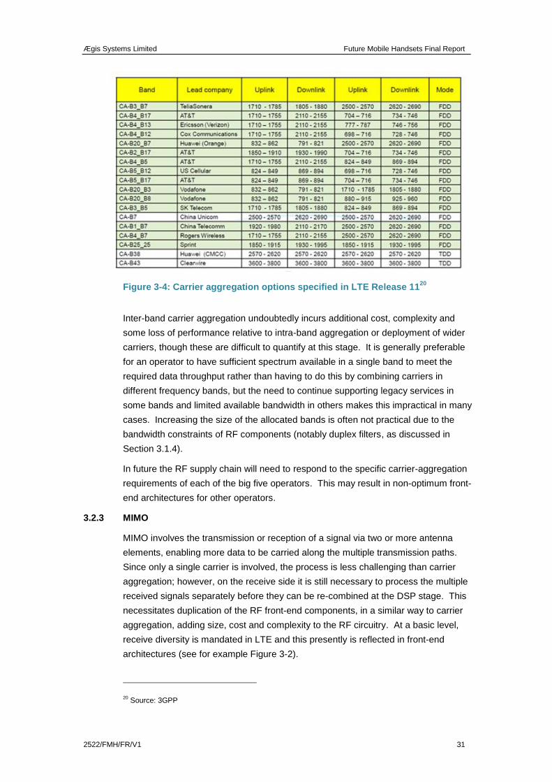
Ægis Systems Limited Future Mobile Handsets Final Report
2522/FMH/FR/V1 31
Figure 3-4: Carrier aggregation options specified in LTE Release 1120
Inter-band carrier aggregation undoubtedly incurs additional cost, complexity and
some loss of performance relative to intra-band aggregation or deployment of wider
carriers, though these are difficult to quantify at this stage. It is generally preferable
for an operator to have sufficient spectrum available in a single band to meet the
required data throughput rather than having to do this by combining carriers in
different frequency bands, but the need to continue supporting legacy services in
some bands and limited available bandwidth in others makes this impractical in many
cases. Increasing the size of the allocated bands is often not practical due to the
bandwidth constraints of RF components (notably duplex filters, as discussed in
Section 3.1.4).
In future the RF supply chain will need to respond to the specific carrier-aggregation
requirements of each of the big five operators. This may result in non-optimum front-
end architectures for other operators.
3.2.3 MIMO
MIMO involves the transmission or reception of a signal via two or more antenna
elements, enabling more data to be carried along the multiple transmission paths.
Since only a single carrier is involved, the process is less challenging than carrier
aggregation; however, on the receive side it is still necessary to process the multiple
received signals separately before they can be re-combined at the DSP stage. This
necessitates duplication of the RF front-end components, in a similar way to carrier
aggregation, adding size, cost and complexity to the RF circuitry. At a basic level,
receive diversity is mandated in LTE and this presently is reflected in front-end
architectures (see for example Figure 3-2).
20 Source: 3GPP
Ægis Systems Limited Future Mobile Handsets Final Report
32 2522/FMH/FR/V1
3.2.4 Co-existence between LTE and other technologies
Certain LTE bands introduce specific challenges in terms of the potential impact on
other radio technologies deployed in user devices. For example:
The 2.6 GHz band introduces the additional challenges to RF front-end
design of managing Wi-Fi and Bluetooth functionality in the adjacent 2.4 GHz
band.
Potential deployment of other services in the duplex gap in the 700 MHz
band (see Figure 2-3) will introduce design and performance challenges
including the need to manage TDD/FDD coexistence and geographically
proximate TV, PMSE and White Space device receive bands. Second-order
products in the GPS receive band (1575 MHz) are also potentially an issue
for this band.
Increasing use of the 5 GHz band for Wi-Fi increases the need to avoid
second- or third-order harmonics or intermodulation products from LTE
devices operating in the 2.6 GHz and 1800 MHz respectively, which might
fall in this band.
3.3 Catering for additional bands above 6 GHz
Research activity is underway in Japan and Korea into the potential for frequencies
above 6 GHz to support very high speed mobile transmission. For example,
Samsung21
has claimed to have achieved a bit rate of 1 Gbps in a mobile
environment using spectrum in the 28 GHz band by deploying an adaptive array
comprising 64 antenna elements. Samsung claims the technology will be sufficiently
developed to incorporate into top-end smartphone devices by as early as 2020,
although our understanding is that the demonstration was based on bulky horn
antennas with a limited antenna beamwidth.
NTT Docomo22
has also demonstrated mobile transmissions of very high bit rates (in
this case 10 Gbps), using 400 MHz of spectrum in the 11 GHz band, but again this is
very much a “concept demonstration” involving a large, vehicle-mounted antenna
array.
21
http://english.yonhapnews.co.kr/techscience/2013/05/12/17/0601000000AEN20130512000900320F.HTML
22 www.nttdocomo.co.jp/english/info/media_center/pr/2013/0227_00.html
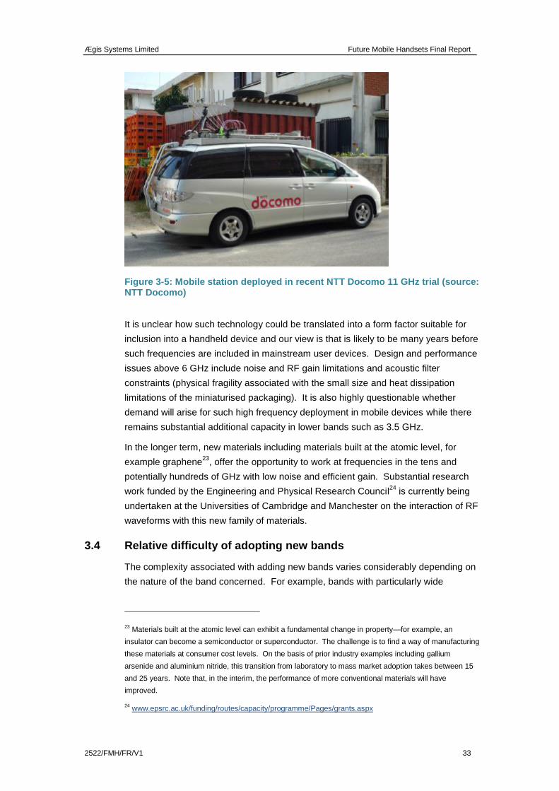
Ægis Systems Limited Future Mobile Handsets Final Report
2522/FMH/FR/V1 33
Figure 3-5: Mobile station deployed in recent NTT Docomo 11 GHz trial (source: NTT Docomo)
It is unclear how such technology could be translated into a form factor suitable for
inclusion into a handheld device and our view is that is likely to be many years before
such frequencies are included in mainstream user devices. Design and performance
issues above 6 GHz include noise and RF gain limitations and acoustic filter
constraints (physical fragility associated with the small size and heat dissipation
limitations of the miniaturised packaging). It is also highly questionable whether
demand will arise for such high frequency deployment in mobile devices while there
remains substantial additional capacity in lower bands such as 3.5 GHz.
In the longer term, new materials including materials built at the atomic level, for
example graphene23
, offer the opportunity to work at frequencies in the tens and
potentially hundreds of GHz with low noise and efficient gain. Substantial research
work funded by the Engineering and Physical Research Council24
is currently being
undertaken at the Universities of Cambridge and Manchester on the interaction of RF
waveforms with this new family of materials.
3.4 Relative difficulty of adopting new bands
The complexity associated with adding new bands varies considerably depending on
the nature of the band concerned. For example, bands with particularly wide
23 Materials built at the atomic level can exhibit a fundamental change in property—for example, an
insulator can become a semiconductor or superconductor. The challenge is to find a way of manufacturing
these materials at consumer cost levels. On the basis of prior industry examples including gallium
arsenide and aluminium nitride, this transition from laboratory to mass market adoption takes between 15
and 25 years. Note that, in the interim, the performance of more conventional materials will have
improved.
24 www.epsrc.ac.uk/funding/routes/capacity/programme/Pages/grants.aspx
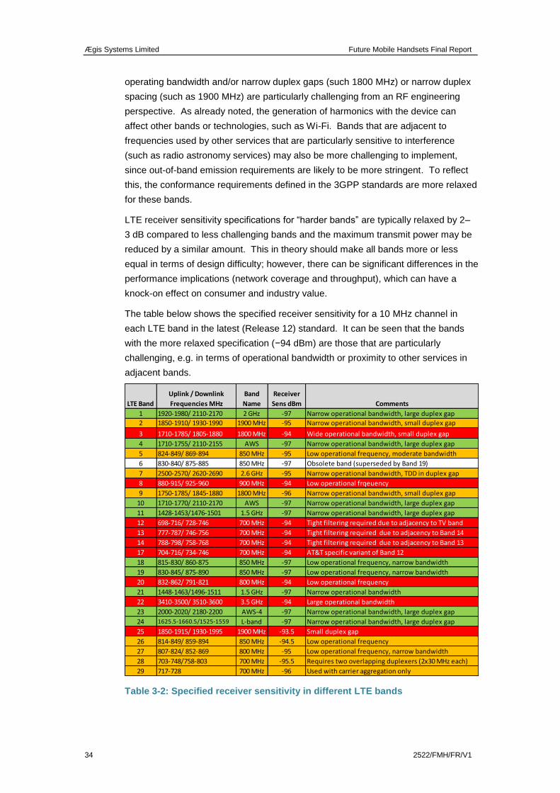
Ægis Systems Limited Future Mobile Handsets Final Report
34 2522/FMH/FR/V1
operating bandwidth and/or narrow duplex gaps (such 1800 MHz) or narrow duplex
spacing (such as 1900 MHz) are particularly challenging from an RF engineering
perspective. As already noted, the generation of harmonics with the device can
affect other bands or technologies, such as Wi-Fi. Bands that are adjacent to
frequencies used by other services that are particularly sensitive to interference
(such as radio astronomy services) may also be more challenging to implement,
since out-of-band emission requirements are likely to be more stringent. To reflect
this, the conformance requirements defined in the 3GPP standards are more relaxed
for these bands.
LTE receiver sensitivity specifications for “harder bands” are typically relaxed by 2–
3 dB compared to less challenging bands and the maximum transmit power may be
reduced by a similar amount. This in theory should make all bands more or less
equal in terms of design difficulty; however, there can be significant differences in the
performance implications (network coverage and throughput), which can have a
knock-on effect on consumer and industry value.
The table below shows the specified receiver sensitivity for a 10 MHz channel in
each LTE band in the latest (Release 12) standard. It can be seen that the bands
with the more relaxed specification (−94 dBm) are those that are particularly
challenging, e.g. in terms of operational bandwidth or proximity to other services in
adjacent bands.
Table 3-2: Specified receiver sensitivity in different LTE bands
1 1920-1980/ 2110-2170 2 GHz -97 Narrow operational bandwidth, large duplex gap
2 1850-1910/ 1930-1990 1900 MHz -95 Narrow operational bandwidth, small duplex gap
3 1710-1785/ 1805-1880 1800 MHz -94 Wide operational bandwidth, small duplex gap
4 1710-1755/ 2110-2155 AWS -97 Narrow operational bandwidth, large duplex gap
5 824-849/ 869-894 850 MHz -95 Low operational frequency, moderate bandwidth
6 830-840/ 875-885 850 MHz -97 Obsolete band (superseded by Band 19)
7 2500-2570/ 2620-2690 2.6 GHz -95 Narrow operational bandwidth, TDD in duplex gap
8 880-915/ 925-960 900 MHz -94 Low operational frqeuency
9 1750-1785/ 1845-1880 1800 MHz -96 Narrow operational bandwidth, small duplex gap
10 1710-1770/ 2110-2170 AWS -97 Narrow operational bandwidth, large duplex gap
11 1428-1453/1476-1501 1.5 GHz -97 Narrow operational bandwidth, large duplex gap
12 698-716/ 728-746 700 MHz -94 Tight filtering required due to adjacency to TV band
13 777-787/ 746-756 700 MHz -94 Tight filtering required due to adjacency to Band 14
14 788-798/ 758-768 700 MHz -94 Tight filtering required due to adjacency to Band 13
17 704-716/ 734-746 700 MHz -94 AT&T specific variant of Band 12
18 815-830/ 860-875 850 MHz -97 Low operational frequency, narrow bandwidth
19 830-845/ 875-890 850 MHz -97 Low operational frequency, narrow bandwidth
20 832-862/ 791-821 800 MHz -94 Low operational frequency
21 1448-1463/1496-1511 1.5 GHz -97 Narrow operational bandwidth
22 3410-3500/ 3510-3600 3.5 GHz -94 Large operational bandwidth
23 2000-2020/ 2180-2200 AWS-4 -97 Narrow operational bandwidth, large duplex gap
24 1625.5-1660.5/1525-1559 L-band -97 Narrow operational bandwidth, large duplex gap
25 1850-1915/ 1930-1995 1900 MHz -93.5 Small duplex gap
26 814-849/ 859-894 850 MHz -94.5 Low operational frequency
27 807-824/ 852-869 800 MHz -95 Low operational frequency, narrow bandwidth
28 703-748/758-803 700 MHz -95.5 Requires two overlapping duplexers (2x30 MHz each)
29 717-728 700 MHz -96 Used with carrier aggregation only
LTE Band
Uplink / Downlink
Frequencies MHz
Band
Name
Receiver
Sens dBm Comments
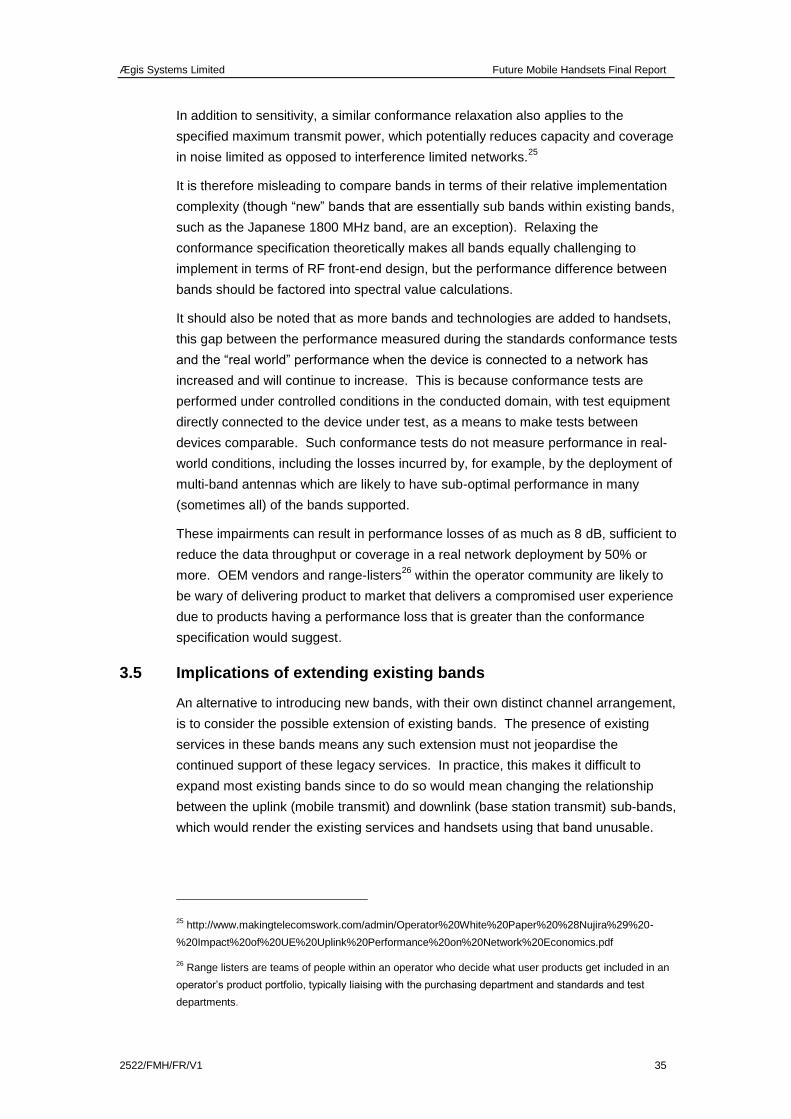
Ægis Systems Limited Future Mobile Handsets Final Report
2522/FMH/FR/V1 35
In addition to sensitivity, a similar conformance relaxation also applies to the
specified maximum transmit power, which potentially reduces capacity and coverage
in noise limited as opposed to interference limited networks.25
It is therefore misleading to compare bands in terms of their relative implementation
complexity (though “new” bands that are essentially sub bands within existing bands,
such as the Japanese 1800 MHz band, are an exception). Relaxing the
conformance specification theoretically makes all bands equally challenging to
implement in terms of RF front-end design, but the performance difference between
bands should be factored into spectral value calculations.
It should also be noted that as more bands and technologies are added to handsets,
this gap between the performance measured during the standards conformance tests
and the “real world” performance when the device is connected to a network has
increased and will continue to increase. This is because conformance tests are
performed under controlled conditions in the conducted domain, with test equipment
directly connected to the device under test, as a means to make tests between
devices comparable. Such conformance tests do not measure performance in real-
world conditions, including the losses incurred by, for example, by the deployment of
multi-band antennas which are likely to have sub-optimal performance in many
(sometimes all) of the bands supported.
These impairments can result in performance losses of as much as 8 dB, sufficient to
reduce the data throughput or coverage in a real network deployment by 50% or
more. OEM vendors and range-listers26
within the operator community are likely to
be wary of delivering product to market that delivers a compromised user experience
due to products having a performance loss that is greater than the conformance
specification would suggest.
3.5 Implications of extending existing bands
An alternative to introducing new bands, with their own distinct channel arrangement,
is to consider the possible extension of existing bands. The presence of existing
services in these bands means any such extension must not jeopardise the
continued support of these legacy services. In practice, this makes it difficult to
expand most existing bands since to do so would mean changing the relationship
between the uplink (mobile transmit) and downlink (base station transmit) sub-bands,
which would render the existing services and handsets using that band unusable.
25 http://www.makingtelecomswork.com/admin/Operator%20White%20Paper%20%28Nujira%29%20-
%20Impact%20of%20UE%20Uplink%20Performance%20on%20Network%20Economics.pdf
26 Range listers are teams of people within an operator who decide what user products get included in an
operator’s product portfolio, typically liaising with the purchasing department and standards and test
departments.
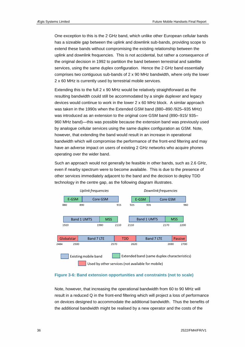
Ægis Systems Limited Future Mobile Handsets Final Report
36 2522/FMH/FR/V1
One exception to this is the 2 GHz band, which unlike other European cellular bands
has a sizeable gap between the uplink and downlink sub-bands, providing scope to
extend these bands without compromising the existing relationship between the
uplink and downlink frequencies. This is not accidental, but rather a consequence of
the original decision in 1992 to partition the band between terrestrial and satellite
services, using the same duplex configuration. Hence the 2 GHz band essentially
comprises two contiguous sub-bands of 2 x 90 MHz bandwidth, where only the lower
2 x 60 MHz is currently used by terrestrial mobile services.
Extending this to the full 2 x 90 MHz would be relatively straightforward as the
resulting bandwidth could still be accommodated by a single duplexer and legacy
devices would continue to work in the lower 2 x 60 MHz block. A similar approach
was taken in the 1990s when the Extended GSM band (880–890 /925–935 MHz)
was introduced as an extension to the original core GSM band (890–915/ 935–
960 MHz band)—this was possible because the extension band was previously used
by analogue cellular services using the same duplex configuration as GSM. Note,
however, that extending the band would result in an increase in operational
bandwidth which will compromise the performance of the front-end filtering and may
have an adverse impact on users of existing 2 GHz networks who acquire phones
operating over the wider band.
Such an approach would not generally be feasible in other bands, such as 2.6 GHz,
even if nearby spectrum were to become available. This is due to the presence of
other services immediately adjacent to the band and the decision to deploy TDD
technology in the centre gap, as the following diagram illustrates.
Figure 3-6: Band extension opportunities and constraints (not to scale)
Note, however, that increasing the operational bandwidth from 60 to 90 MHz will
result in a reduced Q in the front-end filtering which will project a loss of performance
on devices designed to accommodate the additional bandwidth. Thus the benefits of
the additional bandwidth might be realised by a new operator and the costs of the
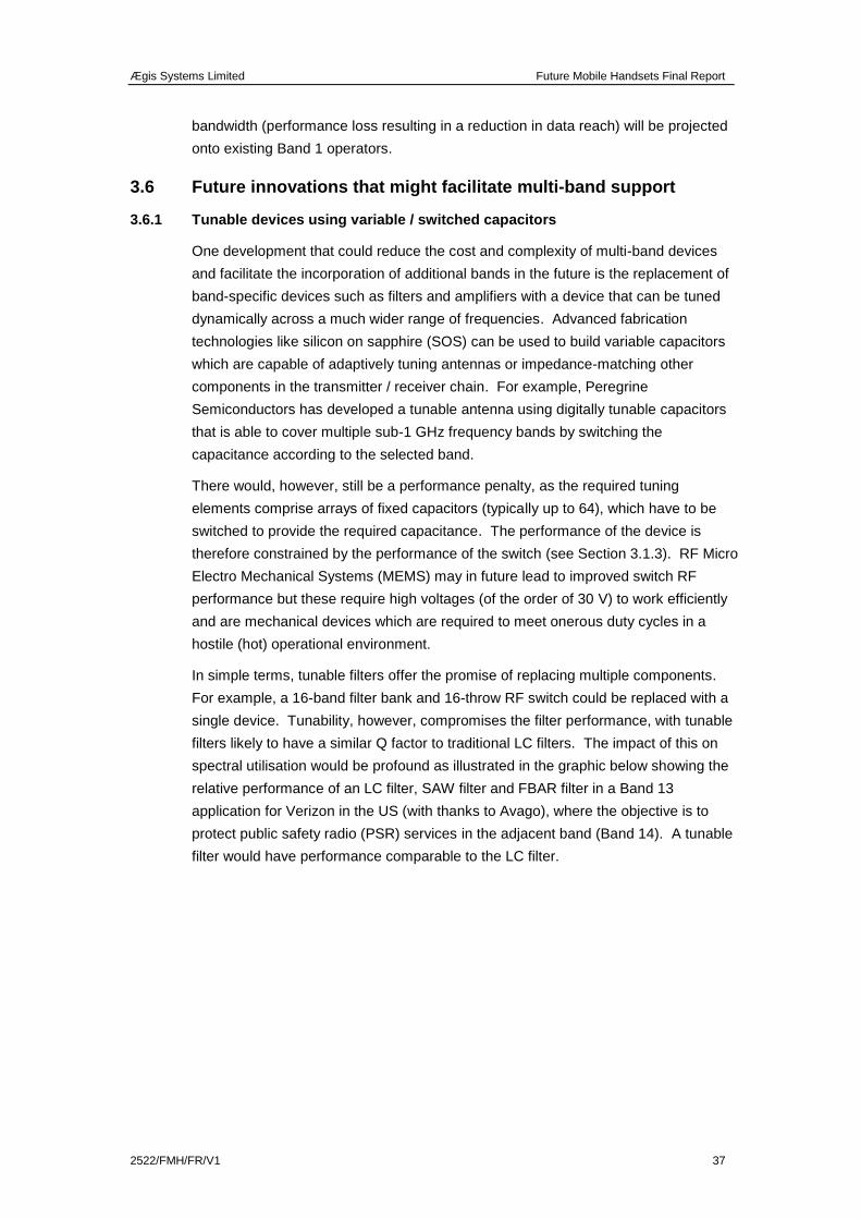
Ægis Systems Limited Future Mobile Handsets Final Report
2522/FMH/FR/V1 37
bandwidth (performance loss resulting in a reduction in data reach) will be projected
onto existing Band 1 operators.
3.6 Future innovations that might facilitate multi-band support
3.6.1 Tunable devices using variable / switched capacitors
One development that could reduce the cost and complexity of multi-band devices
and facilitate the incorporation of additional bands in the future is the replacement of
band-specific devices such as filters and amplifiers with a device that can be tuned
dynamically across a much wider range of frequencies. Advanced fabrication
technologies like silicon on sapphire (SOS) can be used to build variable capacitors
which are capable of adaptively tuning antennas or impedance-matching other
components in the transmitter / receiver chain. For example, Peregrine
Semiconductors has developed a tunable antenna using digitally tunable capacitors
that is able to cover multiple sub-1 GHz frequency bands by switching the
capacitance according to the selected band.
There would, however, still be a performance penalty, as the required tuning
elements comprise arrays of fixed capacitors (typically up to 64), which have to be
switched to provide the required capacitance. The performance of the device is
therefore constrained by the performance of the switch (see Section 3.1.3). RF Micro
Electro Mechanical Systems (MEMS) may in future lead to improved switch RF
performance but these require high voltages (of the order of 30 V) to work efficiently
and are mechanical devices which are required to meet onerous duty cycles in a
hostile (hot) operational environment.
In simple terms, tunable filters offer the promise of replacing multiple components.
For example, a 16-band filter bank and 16-throw RF switch could be replaced with a
single device. Tunability, however, compromises the filter performance, with tunable
filters likely to have a similar Q factor to traditional LC filters. The impact of this on
spectral utilisation would be profound as illustrated in the graphic below showing the
relative performance of an LC filter, SAW filter and FBAR filter in a Band 13
application for Verizon in the US (with thanks to Avago), where the objective is to
protect public safety radio (PSR) services in the adjacent band (Band 14). A tunable
filter would have performance comparable to the LC filter.
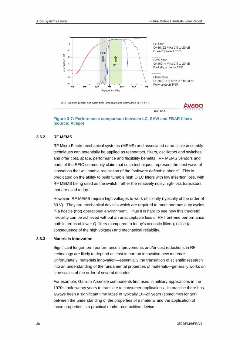
Ægis Systems Limited Future Mobile Handsets Final Report
38 2522/FMH/FR/V1
Figure 3-7: Performance comparison between LC, SAW and FBAR filters (source: Avago)
3.6.2 RF MEMS
RF Micro Electromechanical systems (MEMS) and associated nano-scale assembly
techniques can potentially be applied as resonators, filters, oscillators and switches
and offer cost, space, performance and flexibility benefits. RF MEMS vendors and
parts of the RFIC community claim that such techniques represent the next wave of
innovation that will enable realisation of the “software definable phone”. This is
predicated on the ability to build tunable high Q LC filters with low insertion loss, with
RF MEMS being used as the switch, rather the relatively noisy high-loss transistors
that are used today.
However, RF MEMS require high voltages to work efficiently (typically of the order of
30 V). They are mechanical devices which are required to meet onerous duty cycles
in a hostile (hot) operational environment. Thus it is hard to see how this theoretic
flexibility can be achieved without an unacceptable loss of RF front-end performance
both in terms of lower Q filters (compared to today’s acoustic filters), noise (a
consequence of the high voltage) and mechanical reliability.
3.6.3 Materials innovation
Significant longer term performance improvements and/or cost reductions in RF
technology are likely to depend at least in part on innovative new materials.
Unfortunately, materials innovation—essentially the translation of scientific research
into an understanding of the fundamental properties of materials—generally works on
time scales of the order of several decades.
For example, Gallium Arsenide components first used in military applications in the
1970s took twenty years to translate to consumer applications. In practice there has
always been a significant time lapse of typically 10–20 years (sometimes longer)
between the understanding of the properties of a material and the application of
those properties in a practical market-competitive device.
Ægis Systems Limited Future Mobile Handsets Final Report
2522/FMH/FR/V1 39
Graphene provides a contemporary example. Discovered in 2005, graphene is
graphite deposited as a layer of individual carbon atoms. It has exceptional strength
and conductive properties under certain conditions and has been proposed by IBM
as a frequency mixer with potentially broader applications. Apple has filed patents
covering the use of graphene to conduct heat away from sensitive components and
Nokia has expressed an interest in exploring how the material can be used to build
flexible conducting substrates.
However, commercialisation of graphene in components such as switches or filters or
amplifiers must be considered as being at least 15 years in the future and its shorter-
term impact on band adoption and spectral policy is likely to be minimal at most.
Ægis Systems Limited Future Mobile Handsets Final Report
40 2522/FMH/FR/V1
4 COMMERCIAL AND COST IMPLICATIONS OF NEW-BAND OR
TECHNOLOGY DEPLOYMENT
In general, the addition of more frequency bands or technology variants to a handset
will inevitably introduce extra cost, which needs to be recouped either through higher
prices or higher sales volumes. Whether the latter can be realised depends in part
on whether the new bands or technologies add consumer value to the device. In
practice, while new technologies such as LTE provide improved performance for the
end user (hence increased consumer value), this does not necessarily apply to the
addition of new bands, unless these bands are themselves required to deliver the
new technology. This is the case, for example, with the recently released 800 MHz
and 2600 MHz bands, without which many European operators were unable to
launch LTE services. In general, there is no underlying consumer demand for
extended band support in the absence of a technology improvement (users do not
walk into a shop and ask for a ten-band phone).
In theory there is no upper limit on the number of bands that can be supported in a
device, but in practice the resulting performance degradation does result in a
practical limit, as we have discussed in the previous chapter. Some RFIC and
transceiver module vendors are working on 20 band designs and these could come
to market within two to three design cycles (two to three years). However the 20-
band capability relates only to the transceiver module (see Figure 3-2) and does not
overcome the need to add band-specific switch paths and filter/duplexers for each
new band. The resulting performance loss and additional cost would offset any
potential inventory saving and it is therefore unlikely with current technology that RF
front ends (as opposed to RFICs and transceiver modules) will be able to support
more than 8 or 9 bands whilst remaining competitive in cost and performance terms
In the following sections we review the cost implications of adding further bands
and/or technologies to mobile handsets. We also address other commercial
considerations such as time to market for new devices and the influence of major
market players in different parts of the supply chain.
4.1 Costs associated with new bands and technologies
In 2007 RTT suggested a guideline figure of a dollar per band for each additional
band in a cellular handset and an associated 1 dB of performance loss27
. Our
discussions within the industry supply chain at the time indicated broad agreement
with this estimate, though it was noted that costs and performance losses could vary
considerably in practice. The technical inputs we have received for this current study
suggest that this rough rule of thumb still applies but that the up-front RF-related non-
recurring engineering (NRE) cost has significantly increased. The cost and
27 “A study for the GSMA on the RF cost and performance implications for handsets supporting non-
standard band allocations”, www.rttonline.com/documents/rfcosteconhsetss.pdf.
Ægis Systems Limited Future Mobile Handsets Final Report
2522/FMH/FR/V1 41
performance loss also depends on how aggressive the adoption time scale is in
terms of technology and band complexity.
In general, costs associated with catering for new bands and technologies can be
divided into two broad areas:
non-recurring engineering (product development)
production (bill of materials).
In the following sections we consider each of these elements.
4.1.1 Non-recurring engineering (NRE) costs
NRE costs relate to the research, design, development and testing costs associated
with the launch of a new product or technology. For complex devices like smart
phones NRE costs can be significant, but their impact depends very much on the
size of the addressable market over which the costs can be amortised.
For example, a study by RTT in 201028
estimated the NRE costs associated with the
RFIC chip technology required for LTE and LTE-Advanced devices to be of the order
of $80 million. This excluded the cost of the RF devices that could not be integrated
into the RFIC chips and transceiver module, such as power amplifiers, acoustic
filters, switches and quartz crystals. However, even these costs are relatively small
when compared to the system support costs required to apply the components into a
well-designed and market-competitive end product. For example, Nokia’s former RF
design team of 1,400 engineers would have been costing approximately $300 million
per year in operating costs and it is not unusual to have a head count of 2,000
system engineers to support a major mobile phone platform development.29
This expenditure is predominantly RFIC and transceiver module development and
does not include the research budgets of third-party component suppliers.
Significantly, several stakeholders that we spoke to in this study have independently
commented that support costs are escalating significantly in the filter, PA and switch
businesses, all of which are vital components of mobile phone handsets. These
costs increase as additional bands are added.
Historically, NRE costs have risen by approximately an order of magnitude for each
generation of mobile technology, as illustrated in the following table. Note that these
figures include the RFIC NRE and directly associated RF front-end costs including
system support costs.
28 http://www.makingtelecomswork.com/admin/LTE%20User%20Equipment.pdf page 41
29 Discussion with RFIC vendor.
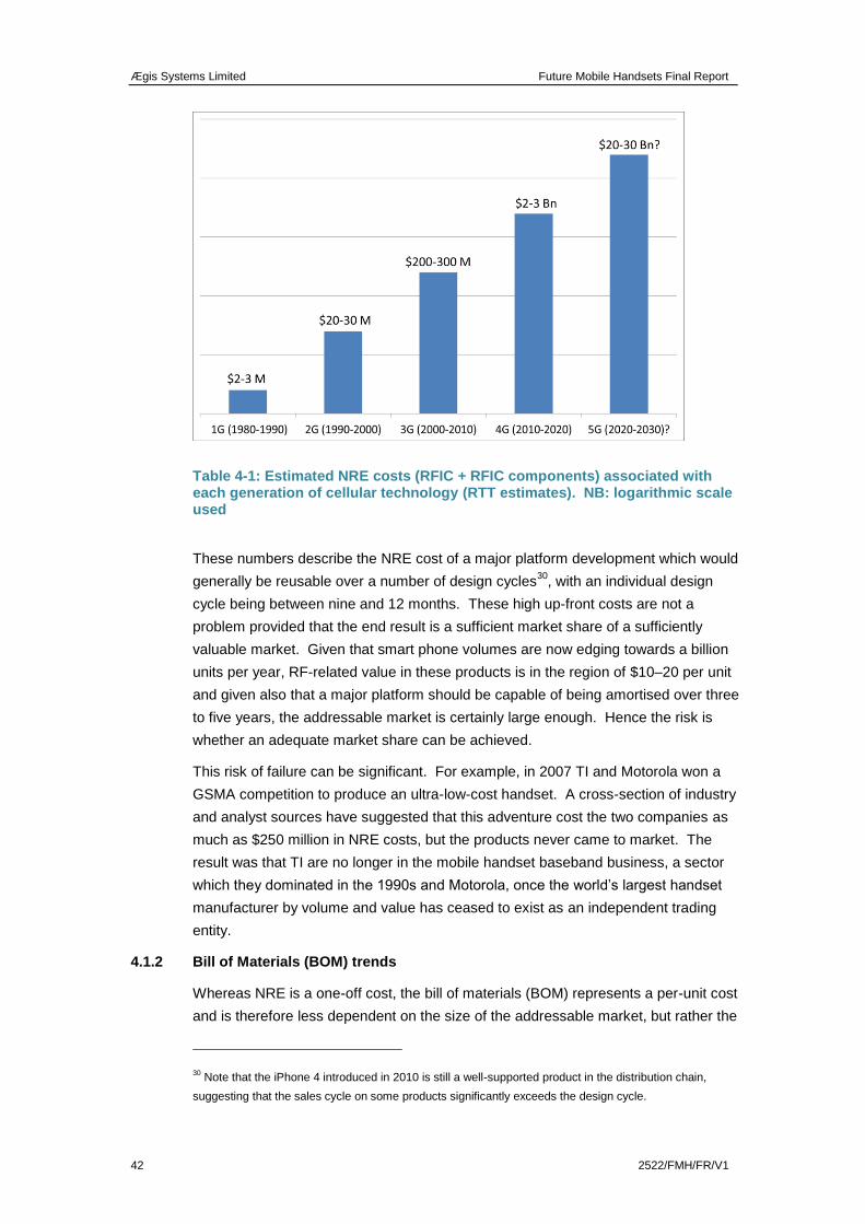
Ægis Systems Limited Future Mobile Handsets Final Report
42 2522/FMH/FR/V1
Table 4-1: Estimated NRE costs (RFIC + RFIC components) associated with each generation of cellular technology (RTT estimates). NB: logarithmic scale used
These numbers describe the NRE cost of a major platform development which would
generally be reusable over a number of design cycles30
, with an individual design
cycle being between nine and 12 months. These high up-front costs are not a
problem provided that the end result is a sufficient market share of a sufficiently
valuable market. Given that smart phone volumes are now edging towards a billion
units per year, RF-related value in these products is in the region of $10–20 per unit
and given also that a major platform should be capable of being amortised over three
to five years, the addressable market is certainly large enough. Hence the risk is
whether an adequate market share can be achieved.
This risk of failure can be significant. For example, in 2007 TI and Motorola won a
GSMA competition to produce an ultra-low-cost handset. A cross-section of industry
and analyst sources have suggested that this adventure cost the two companies as
much as $250 million in NRE costs, but the products never came to market. The
result was that TI are no longer in the mobile handset baseband business, a sector
which they dominated in the 1990s and Motorola, once the world’s largest handset
manufacturer by volume and value has ceased to exist as an independent trading
entity.
4.1.2 Bill of Materials (BOM) trends
Whereas NRE is a one-off cost, the bill of materials (BOM) represents a per-unit cost
and is therefore less dependent on the size of the addressable market, but rather the
30 Note that the iPhone 4 introduced in 2010 is still a well-supported product in the distribution chain,
suggesting that the sales cycle on some products significantly exceeds the design cycle.
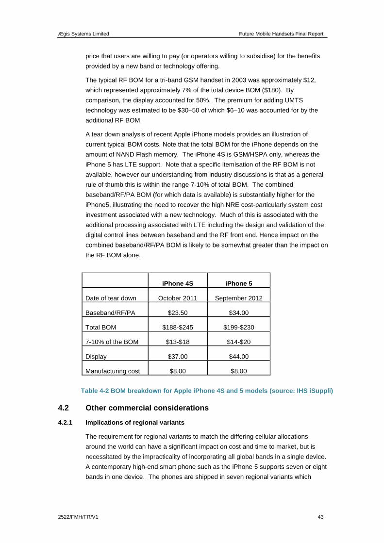
Ægis Systems Limited Future Mobile Handsets Final Report
2522/FMH/FR/V1 43
price that users are willing to pay (or operators willing to subsidise) for the benefits
provided by a new band or technology offering.
The typical RF BOM for a tri-band GSM handset in 2003 was approximately $12,
which represented approximately 7% of the total device BOM ($180). By
comparison, the display accounted for 50%. The premium for adding UMTS
technology was estimated to be $30–50 of which $6–10 was accounted for by the
additional RF BOM.
A tear down analysis of recent Apple iPhone models provides an illustration of
current typical BOM costs. Note that the total BOM for the iPhone depends on the
amount of NAND Flash memory. The iPhone 4S is GSM/HSPA only, whereas the
iPhone 5 has LTE support. Note that a specific itemisation of the RF BOM is not
available, however our understanding from industry discussions is that as a general
rule of thumb this is within the range 7-10% of total BOM. The combined
baseband/RF/PA BOM (for which data is available) is substantially higher for the
iPhone5, illustrating the need to recover the high NRE cost-particularly system cost
investment associated with a new technology. Much of this is associated with the
additional processing associated with LTE including the design and validation of the
digital control lines between baseband and the RF front end. Hence impact on the
combined baseband/RF/PA BOM is likely to be somewhat greater than the impact on
the RF BOM alone.
iPhone 4S iPhone 5
Date of tear down October 2011 September 2012
Baseband/RF/PA $23.50 $34.00
Total BOM $188-$245 $199-$230
7-10% of the BOM $13-$18 $14-$20
Display $37.00 $44.00
Manufacturing cost $8.00 $8.00
Table 4-2 BOM breakdown for Apple iPhone 4S and 5 models (source: IHS iSuppli)
4.2 Other commercial considerations
4.2.1 Implications of regional variants
The requirement for regional variants to match the differing cellular allocations
around the world can have a significant impact on cost and time to market, but is
necessitated by the impracticality of incorporating all global bands in a single device.
A contemporary high-end smart phone such as the iPhone 5 supports seven or eight
bands in one device. The phones are shipped in seven regional variants which
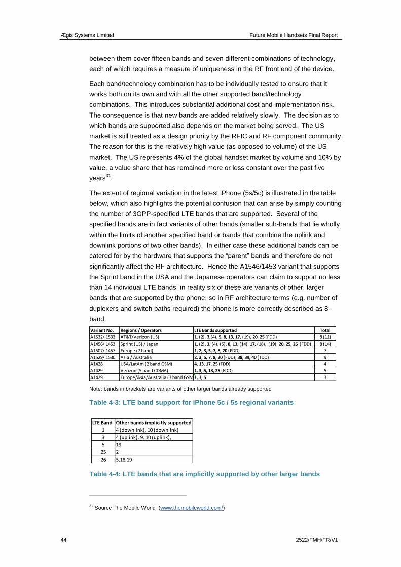
Ægis Systems Limited Future Mobile Handsets Final Report
44 2522/FMH/FR/V1
between them cover fifteen bands and seven different combinations of technology,
each of which requires a measure of uniqueness in the RF front end of the device.
Each band/technology combination has to be individually tested to ensure that it
works both on its own and with all the other supported band/technology
combinations. This introduces substantial additional cost and implementation risk.
The consequence is that new bands are added relatively slowly. The decision as to
which bands are supported also depends on the market being served. The US
market is still treated as a design priority by the RFIC and RF component community.
The reason for this is the relatively high value (as opposed to volume) of the US
market. The US represents 4% of the global handset market by volume and 10% by
value, a value share that has remained more or less constant over the past five
years31
.
The extent of regional variation in the latest iPhone (5s/5c) is illustrated in the table
below, which also highlights the potential confusion that can arise by simply counting
the number of 3GPP-specified LTE bands that are supported. Several of the
specified bands are in fact variants of other bands (smaller sub-bands that lie wholly
within the limits of another specified band or bands that combine the uplink and
downlink portions of two other bands). In either case these additional bands can be
catered for by the hardware that supports the “parent” bands and therefore do not
significantly affect the RF architecture. Hence the A1546/1453 variant that supports
the Sprint band in the USA and the Japanese operators can claim to support no less
than 14 individual LTE bands, in reality six of these are variants of other, larger
bands that are supported by the phone, so in RF architecture terms (e.g. number of
duplexers and switch paths required) the phone is more correctly described as 8-
band.
Note: bands in brackets are variants of other larger bands already supported
Table 4-3: LTE band support for iPhone 5c / 5s regional variants
Table 4-4: LTE bands that are implicitly supported by other larger bands
31 Source The Mobile World (www.themobileworld.com/)
Variant No. Regions / Operators LTE Bands supported Total
A1532/ 1533 AT&T/Verizon (US) 1, (2), 3,(4), 5, 8, 13, 17, (19), 20, 25 (FDD) 8 (11)
A1456/ 1453 Sprint (US) / Japan 1, (2), 3, (4), (5), 8, 13, (14), 17, (18), (19), 20, 25, 26 (FDD) 8 (14)
A1507/ 1457 Europe (7 band) 1, 2, 3, 5, 7, 8, 20 (FDD) 7
A1529/ 1530 Asia / Australia 2, 3, 5, 7, 8, 20 (FDD); 38, 39, 40 (TDD) 9
A1428 USA/LatAm (2 band GSM) 4, 13, 17, 25 (FDD) 4
A1429 Verizon (5 band CDMA) 1, 3, 5, 13, 25 (FDD) 5
A1429 Europe/Asia/Australia (3 band GSM)1, 3, 5 3
LTE Band Other bands implicitly supported
1 4 (downlink), 10 (downlink)
3 4 (uplink), 9, 10 (uplink),
5 19
25 2
26 5,18,19
Ægis Systems Limited Future Mobile Handsets Final Report
2522/FMH/FR/V1 45
4.2.2 Influence of multi-national operators on frequency band and technology
support
In addition to regional and country-specific band plans or technical requirements
there is also a discernible trend towards cross-regional operator-specific band plans.
RF component specifications and architectures are substantially influenced by the
rate at which new technical releases are adopted by individual operators. This
extends to operator-specific preferences, e.g. for inter-band and intra-band carrier
aggregation (e.g. see Figure 3-4). Large operators are also introducing or in some
cases reintroducing their own performance test regimes, adding costs for the supply
chain and absorbing engineering resource. The effect is to introduce additional
design risk, time-to-market risk and performance risk. Conformance and
performance test costs and test time will therefore continue to increase over time.
These risks and costs are all determining factors that dictate whether the supply
chain is willing or able to support additional bands.
The priority allocated to resolving band-specific and technology-specific issues is
dependent on a range of factors. If an operator is sufficiently large (a buying power
of the order of billions of dollars per year) then solutions are likely to be realised for
particular bands irrespective of how difficult they are. However, there are globally at
the most five operators with this degree of consolidated market scale32
. The rest of
the operator community (500+ operators) essentially have to buy whatever is
available and the choice of band/technology mix is determined by OEM supply chain
economics. For these operators, the cost of servicing a small and difficult band
combination will greatly exceed any possible realised value.
4.2.3 Mitigating the impact of regional variation
For both device vendors and operators there would be clear benefits in having a
single phone product that could serve all markets. In practice, the additional cost,
time to market and performance degradation that this would incur necessitates a
regional approach concentrating on the highest-value markets.
A partial solution is to find ways to make it easier to produce regionally-specific,
country-specific and operator-specific band plan variants. A current example is the
RF360 Front End platform from Qualcomm, which is partitioned as four separate but
interlinked modules.
32 AT&T, Verizon, China Mobile, Vodafone and Telefonica
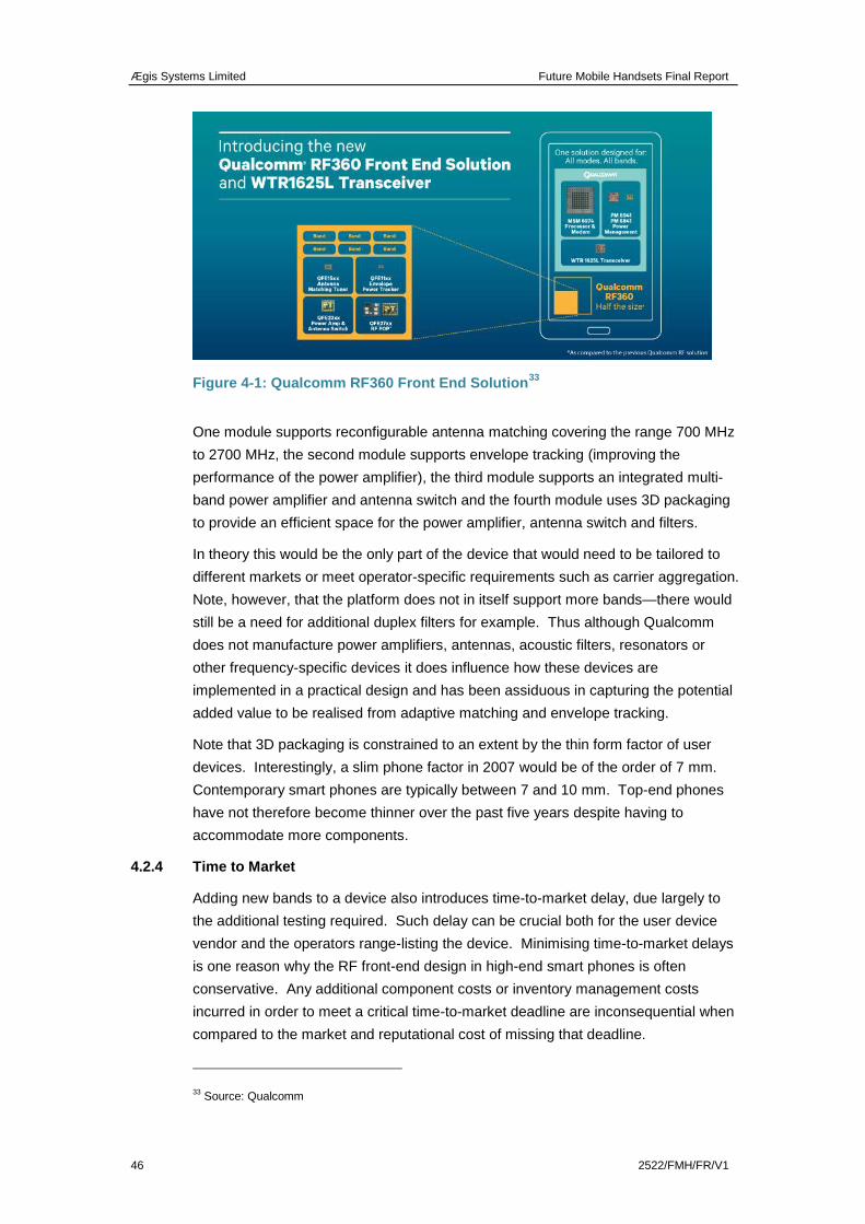
Ægis Systems Limited Future Mobile Handsets Final Report
46 2522/FMH/FR/V1
Figure 4-1: Qualcomm RF360 Front End Solution33
One module supports reconfigurable antenna matching covering the range 700 MHz
to 2700 MHz, the second module supports envelope tracking (improving the
performance of the power amplifier), the third module supports an integrated multi-
band power amplifier and antenna switch and the fourth module uses 3D packaging
to provide an efficient space for the power amplifier, antenna switch and filters.
In theory this would be the only part of the device that would need to be tailored to
different markets or meet operator-specific requirements such as carrier aggregation.
Note, however, that the platform does not in itself support more bands—there would
still be a need for additional duplex filters for example. Thus although Qualcomm
does not manufacture power amplifiers, antennas, acoustic filters, resonators or
other frequency-specific devices it does influence how these devices are
implemented in a practical design and has been assiduous in capturing the potential
added value to be realised from adaptive matching and envelope tracking.
Note that 3D packaging is constrained to an extent by the thin form factor of user
devices. Interestingly, a slim phone factor in 2007 would be of the order of 7 mm.
Contemporary smart phones are typically between 7 and 10 mm. Top-end phones
have not therefore become thinner over the past five years despite having to
accommodate more components.
4.2.4 Time to Market
Adding new bands to a device also introduces time-to-market delay, due largely to
the additional testing required. Such delay can be crucial both for the user device
vendor and the operators range-listing the device. Minimising time-to-market delays
is one reason why the RF front-end design in high-end smart phones is often
conservative. Any additional component costs or inventory management costs
incurred in order to meet a critical time-to-market deadline are inconsequential when
compared to the market and reputational cost of missing that deadline.
33 Source: Qualcomm
Ægis Systems Limited Future Mobile Handsets Final Report
2522/FMH/FR/V1 47
4.2.5 The impact of RFIC vendor consolidation on multi band support
Industry consolidation has led to there being a relatively limited number of LTE IC
vendors. Qualcomm is the market leader. Other vendors include, Intel/Infineon,
Sequans, Broadcom (who recently acquired the intellectual property of the Renesas
design group—formerly Nokia LTE), Ericsson and MediaTek. In the future, Chinese
vendors could be expected to play an increasingly significant role in the RF supply
chain. For example, MediaTek already supplies RFIC and front-end solutions to ZTE
and Huawei, the two largest China-based handset vendors. MediaTek also supplies
Micromax, an Indian-based vendor enjoying strong growth both in its domestic
market and well placed to take market share in non-domestic markets). However, it
is likely that such vendors will be more driven by LTE technology cost minimisation
both for their own home markets and low-ARPU markets such as Africa and Latin
America rather than driving new band support.
Note that for operators servicing these low-ARPU markets, cost reduction is more
important than band count. Low-ARPU markets can only be cost-effectively serviced
with sparse networks (large macrocells). These require handsets that are optimised
in terms of RF transmit and receive front-end efficiency. High band count is thus a
disadvantage both in terms of cost and RF performance.
Ægis Systems Limited Future Mobile Handsets Final Report
48 2522/FMH/FR/V1
5 CONCLUSIONS
Adding frequency bands and/or new technology options to cellular terminals
inevitably adds cost, both in monetary terms (NRE, BOM and test costs) and reduced
performance. This is because each additional band requires an additional switch
path for the band-specific duplexer and newer technologies such as HSPA and LTE
require more linearity and more filtering than legacy technologies such as GSM. LTE
also requires a second antenna to support receive diversity. Hence a more complex
RFIC architecture is required.
The performance loss is typically 1 dB loss in sensitivity per additional band or
technology, which affects all existing legacy bands and technologies and in the case
of 3G or 4G networks could reduce data throughput by as much as 10–20% in some
parts of the coverage area, or requires a corresponding increase in base station
density. Adding bands also incurs risks, in particular of extended time to market (an
important factor when industry design cycles are 9–12 months) and the possibility
that the incurred costs may not be fully amortised over a product’s market life cycle.
From a technical perspective some bands are more difficult to implement than others.
These differences are partially offset by relaxed conformance specifications but still
result in a performance loss. Even an apparently easy band addition, such as the
potential extension of the 2 GHz band (LTE Band 1) into the neighbouring MSS
band, will result in an increase in operational bandwidth which will compromise the
performance of the front-end filtering34
.
The need for additional bands has to date largely been driven by the need to support
emerging new technologies that cannot be accommodated in existing bands because
these are fully utilised by existing technologies. For example, the 2 GHz band was
required to support 3G services and more recently the 800 MHz and 2600 MHz
bands were required to support the widespread launch of 4G LTE services. There is
likely to be less enthusiasm for adding further bands where these do not bring
specific technology enhancements, though a likely exception should be the adoption
of 700 MHz in Europe, where the additional capacity combined with attractive
coverage and the near-global availability of the band are likely to outweigh the cost
and performance penalties incurred in other bands.
In terms of the short to medium term (five years), our research has largely confirmed
that both operators and RF vendors are focussing on a limited set of “core” bands,
comprising the legacy 2G and 3G bands, the more recently released digital dividend
bands below 1 GHz and additional capacity bands above 2 GHz, notably 2.6 GHz
and (to a more limited extent) 2.3 GHz. Although the operator community has been
34 The operational bandwidth will be increased from 3.1% to 4.6%. A 90 MHz duplex would be marginally
harder than the 30 by 30 MHz bands at 700 MHz, not impossible but difficult enough to impose a
performance loss on existing Band 1 operator customers. Note the benefits of the new band accrue to the
new owner of the band, the performance costs are projected on the existing incumbents.
Ægis Systems Limited Future Mobile Handsets Final Report
2522/FMH/FR/V1 49
pressing for additional bands to be released (e.g. around 1.4 GHz and 2.8 GHz)
there appears to be little or no current interest in such developments among the RF
device community. Similarly, there appears to be little interest currently in supporting
the 3.5 GHz band in mainstream cellular devices, although this band may be
attractive for more specialised applications (e.g. supporting dongles) in this time
scale.
Rather than focussing on more bands (beyond those already identified for IMT), the
RF industry appears to be more engaged in facilitating technology enhancements
such as MIMO and carrier aggregation, and in further extending new standards
across the existing legacy bands. This reflects a widely held view that simply adding
more bands to a handset does not in itself make the device more attractive to the
consumer (indeed it may make it less attractive should any degradation in
performance be noticeable by users), but adding technology enhancements will
increase the appeal. Additionally, for low-ARPU markets, OEM vendors and
operators have a particular requirement for low-cost LTE user devices with good RF
performance (optimised for use in sparse networks with large macrocells). High
band count phones are therefore non-optimum for these markets both in terms of
cost and performance.
There is considerable uncertainty over what may happen in the longer term as this
largely depends on developments in relation to tunable antennas and other
frequency-dependent RF components or the development of new materials. Some
stakeholders are optimistic, suggesting the tunable devices required to provide a fully
flexible RF front end could be available as soon as 2017, whereas others suggest
these may never be realised in a way that meets progressively more onerous
performance and cost expectations. Our own view is that such developments are
unlikely to have a significant impact on handset RF design over at least the next
decade.
Whatever happens, it seems unlikely that there will be any significant move away
from the current focus on a limited number of regional core bands, albeit the number
of these bands will increase over time (e.g. with the release of 600 MHz in the US
and 700 MHz in Europe). Other non-core bands such as 3.5 GHz may well remain
the preserve of more specialist applications such as dongles for the foreseeable
future.