Embed Size (px)
Citation preview
FIREPLACE PRODUCTS INTERNATIONAL LTD. 6988 Venture St., Delta, BC Canada, V4G 1H4908-288
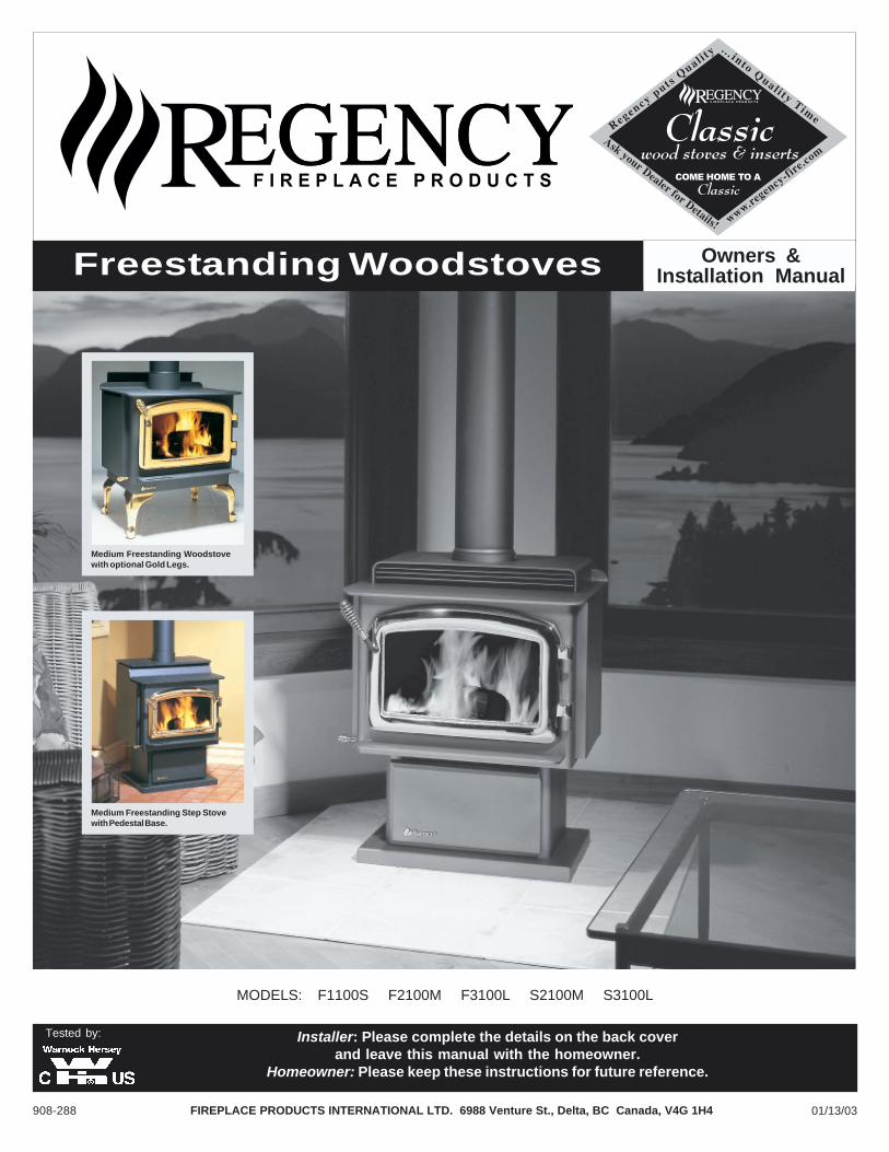
MODELS: F1100S F2100M F3100L S2100M S3100L
Freestanding Woodstoves
01/13/03
Tested by: Installer: Please complete the details on the back coverand leave this manual with the homeowner.
Homeowner: Please keep these instructions for future reference.
Medium Freestanding Step Stovewith Pedestal Base.
Medium Freestanding Woodstovewith optional Gold Legs.
Owners &Installation Manual
Regency Freestanding Woodstove2
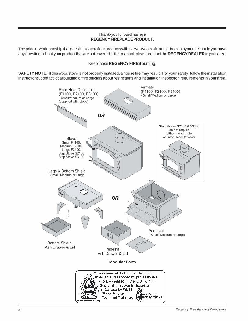
Thank-you for purchasing aREGENCY FIREPLACE PRODUCT.
The pride of workmanship that goes into each of our products will give you years of trouble-free enjoyment. Should you haveany questions about your product that are not covered in this manual, please contact the REGENCY DEALER in your area.
Keep those REGENCY FIRES burning.
SAFETY NOTE: If this woodstove is not properly installed, a house fire may result. For your safety, follow the installationinstructions, contact local building or fire officials about restrictions and installation inspection requirements in your area.
Modular Parts
Regency Freestanding Woodstove 3
TABLE OF CONTENTS
THE REGENCY FREESTANDING STOVE
Door Handle ...................................................................... 17
Glass Installation .............................................................. 17
Optional Accessories
- Pedestal Ash Drawer Kit .......................................... 17
- Bottom Shield Ashdrawer Kit ................................... 17
- Blower/Fan ............................................................... 18
- Blower/Fan Wiring Diagram .................................... 18
OPERATING INSTRUCTIONS
Operating Instructions ....................................................... 19
Draft Control ...................................................................... 19
First Fire ............................................................................. 19
Fan Operation .................................................................... 19
Ash Disposal ..................................................................... 20
- Ash Drawer Operating Guidelines ........................... 20
Safety Guidelines .............................................................. 20
MAINTENANCE
Maintenance ...................................................................... 20
Creosote ............................................................................ 21
- Ways to Prevent & Keep Units Free of Creosote ..... 21
Maintenance of Gold Doors .............................................. 21
Latch Adjustment ............................................................... 21
Door Gasket ...................................................................... 21
Glass Maintenance ........................................................... 21
- Glass Replacement ................................................. 21
Parts List - F1100, F2100, F3100 ..................................... 22
Parts List - S2100, S3100 ................................................. 23
Parts List - Pedestal, Bottom Shield and Legs ................ 24
Parts List - Firebrick .......................................................... 25
WARRANTY
Warranty ............................................................................. 27
SAFETY LABEL
Small Freestanding Stove F1100S ..................................... 4
Medium Freestanding Stove F2100M ................................. 5
Large Freestanding Stove F3100L ..................................... 6
Medium Freestanding Step Stove S2100M ........................ 7
Large Freestanding Step Stove S3100L ............................. 8
INSTALLATION
Residential Installation ....................................................... 9
Room Air .............................................................................. 9
Modular Installation Options ............................................... 9
Minimum Clearance to Combustibles .............................. 10
Residential "C" Vent Single Wall ....................................... 10
Residential Close Clearance ........................................... 10
Mobile Home Close Clearance ........................................ 10
Minimum Alcove Clearances ............................................ 11
Floor Protection ................................................................. 11
Stove Assembly Prior to Installation ................................. 12
Airmate Assembly ............................................................. 12
Rear Heat Deflector Assembly .......................................... 12
Side Shield Adjustment for the S2100 & S3100 ............... 12
Pedestal Assembly ........................................................... 12
Leg and Bottom Shield Assembly .................................... 13
Chimney & Connector Installation .................................... 13
Flue Height Table .............................................................. 14
Recommended Height for Woodstove Flue ..................... 14
Mobile Home Installation .................................................. 14
Listed Components for Mobile Home Installation
- U.S. Installations ...................................................... 15
- Canadian Installations ............................................. 15
Brick Flue Baffle & Secondary Air Tube Installation
- Large Stove F3100L & S3100L ................................ 15
- Medium Stove F2100M/S2100 ................................. 16
- Small Stove F1100S ................................................ 16
Brick Installation ................................................................ 17
Regency Freestanding Woodstove4
HOT WHILE IN OPERATION DO NOT TOUCH. KEEP CHILDREN,CLOTHING AND FURNITURE AWAY. CONTACT MAY CAUSE
SKIN BURNS. READ NAMEPLATE AND INSTRUCTIONS.
DO NOT REMOVE THIS LABEL
FLOORPROTECTION*
F1100S WITHAIRMATE SHIELD
LISTED SPACE HEATER, SOLID FUEL TYPE, ALSOSUITABLE FOR MOBILE HOME INSTALLATION
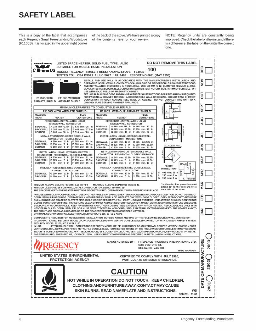
MODEL: REGENCY SMALL FREESTANDING STOVE - F1100STESTED TO: CSA B366.2 / ULC S627 / UL 1482 REPORT NO.6621 (MAY 1993)
F1100S WITHOUTAIRMATE SHIELD
INSTALL AND USE ONLY IN ACCORDANCE WITH THE MANUFACTURER'S INSTALLATION ANDOPERATING INSTRUCTIONS. CONTACT LOCAL BUILDING OR FIRE OFFICIALS ABOUT RESTRICTIONSAND INSTALLATION INSPECTION IN YOUR AREA. USE 150 MM (6 IN.) DIAMETER MINIMUM 24 MSGBLACK OR 26 MSG BLUED STEEL CONNECTOR WITH LISTED FACTORY-BUILT CHIMNEY SUITABLE FORUSE WITH SOLID FUELS OR MASONRY CHIMNEY.SEE LOCAL BUILDING CODE AND MANUFACTURER'S INSTRUCTIONS FOR PRECAUTIONS REQUIREDFOR PASSING A CHIMNEY THROUGH A COMBUSTIBLE WALL OR CEILING. DO NOT PASS CHIMNEYCONNECTOR THROUGH COMBUSTIBLE WALL OR CEILING. DO NOT CONNECT THIS UNIT TO ACHIMNEY FLUE SERVING ANOTHER APPLIANCE.
FRONT
BACK
L
K
M
SID
E
SID
EK 405 mm / 16 inL 150 mm / 6 inM 150 mm / 6 in
COMPONENTS REQUIRED FOR MOBILE HOME INSTALLATION: OUTSIDE AIR KIT AND ONE OF THE FOLLOWING DOUBLE WALL CONNECTORIN CANADA: LISTED SECURITY MODEL DP, OR OLIVER MACLEOD PRO-VENT PV DOUBLE WALLED CONNECTOR WITH LISTED CHIMNEY SYSTEM:SECURITY MODEL S2100, ICC EXCEL 2100 .IN USA: LISTED DOUBLE WALL CONNECTORS SECURITY MODEL DP, SELKIRK MODEL DS, OLIVER MACLEOD PRO VENT PV, SIMPSON DURAVENT MODEL DVL, GSW SUPER PIPE 6, METAL-FAB DOUBLE WALL. CONNECTED TO ONE OF THE FOLLOWING COMPATIBLE CHIMNEY SYSTEMSSECURITY MODEL S2100 OR MODEL ASHT, SELKIRK MODEL SSII, OLIVER MACLEOD PRO JET 3103, SIMPSON DURA PLUS, GSW MODEL SC OR METAL-FAB TEMP/GUARD, AMERI-TEC HS, ICC EXCEL 2100 . USE CHIMNEY COMPONENTS AS SPECIFIED IN INSTALLATION INSTRUCTIONS.
CERTIFIED TO COMPLY WITH JULY 1990,PARTICULATE EMISSION STANDARDS.
UNITED STATES ENVIRONMENTALPROTECTION AGENCY
FOR USE WITH SOLID WOOD FUEL ONLY. USE OF OTHER FUELS MAY DAMAGE HEATER AND CREATE A HAZARDOUS CONDITION. DO NOT OBSTRUCTCOMBUSTION AIR OPENINGS. OPERATE ONLY WITH FIREBRICKS IN PLACE. OPERATE ONLY WITH DOOR CLOSED - OPEN FEED DOOR TO FEED FIREONLY. DO NOT USE GRATE OR ELEVATE FIRE. BUILD WOOD FIRE DIRECTLY ON HEARTH. DO NOT OVERFIRE - IF HEATER OR CHIMNEY CONNECTORGLOWS YOU ARE OVERFIRING. INSPECT AND CLEAN CHIMNEY AND CONNECTOR FREQUENTLY. UNDER CERTAIN CONDITIONS OF USE CREOSOTEBUILDUP MAY OCCUR RAPIDLY. KEEP FURNISHINGS AND OTHER COMBUSTIBLE MATERIAL AWAY FROM HEATER. REPLACE GLASS ONLY WITHNEOCERAM GLASS. COMBUSTIBLE FLOOR MUST BE PROTECTED BY NON-COMBUSTIBLE MATERIAL EXTENDING BENEATH THE HEATER AND TOTHE FRONT AND SIDES AS INDICATED OR TO THE NEAREST PERMITTED COMBUSTIBLE MATERIAL.OPTIONAL COMPONENT: FAN, ELECTRICAL RATING: VOLTS 115, 60 HZ, 2 AMPS
MINIMUM CLEARANCES TO COMBUSTIBLE MATERIALS
F1100S WITH AIRMATE SHIELD F1100S WITHOUT AIRMATE SHIELD
RESIDENTIAL INSTALLATION USING SINGLE WALL CONNECTOR
MEASURE FLUEFROM HEATER CENTER-LINE
RESIDENTIAL INSTALLATION USING SINGLE WALL CONNECTOR
SIDEWALL A 380 mm /15 in D 685 mm / 27 inBACKWALL B 265 mm / 10.5in E 430 mm / 17 inCORNER C 280 mm / 11 in F 585 mm / 23 in
INSTALLATION USING LISTED DOUBLE WALLCONNECTOR - MOBILE HOME
SIDEWALL A 330 mm / 13 in D 635 mm / 25 inBACKWALL B 125 mm / 5 in E 290 mm / 11.5inCORNER C 230 mm / 9 in F 535 mm / 21 in
INSTALLATION USING LISTED DOUBLE WALLCONNECTOR - RESIDENTIAL CLOSE CLEARANCE
SIDEWALL A 345 mm / 13.5in D 650 mm / 25.5inBACKWALL B 125 mm / 5 in E 290 mm / 11.5inCORNER C 125 mm / 5 in F 430 mm / 17 in
INSTALLATION USING LISTED DOUBLE WALLCONNECTOR - ALCOVE
SIDEWALL A 330 mm / 13 in D 635 mm / 25 inBACKWALL B 280 mm / 11 in E 445 mm / 17.5inCORNER C 205 mm / 8 in F 510 mm / 20 in
INSTALLATION USING LISTED DOUBLE WALLCONNECTOR - MOBILE HOME
SIDEWALL A 280 mm / 11 in D 585 mm / 23 inBACKWALL B 150 mm / 6 in E 320 mm / 12.5inCORNER C 150 mm / 6 in F 460 mm / 18 in
SIDEWALL A 230 mm / 9 in D 535 mm / 21 inBACKWALL B 125 mm / 5 in E 290 mm / 11.5inCORNER C 75 mm / 3 in F 380 mm / 15 in
INSTALLATION USING LISTED DOUBLE WALLCONNECTOR - RESIDENTIAL CLOSE CLEARANCE
SIDEWALL G 280 mm / 11 in I 585 mm / 23 inBACKWALL H 180 mm / 7 in J 345 mm / 13.5in
INSTALLATION USING LISTED DOUBLE WALLCONNECTOR - ALCOVE
SIDEWALL G 330 mm / 13 in I 635 mm / 25 inBACKWALL H 125 mm / 5 in J 290 mm / 11.5in
MINIMUM ALCOVE CEILING HEIGHT: 2.15 M / 7 FT MAXIMUM ALCOVE DEPTH 915 MM / 36 IN.MINIMUM CLEARANCES FOR HORIZONTAL CONNECTOR TO CEILING: 455 MM / 18"THE SPACE BENEATH THE HEATER MUST NOT BE OBSTRUCTED. OPERATE ONLY WITH FIREBRICKS IN PLACE.
MEASURE FLUEFROM HEATER CENTER-LINE
MADE IN CANADA
JA
N F
EB
MA
R A
PR
MA
Y J
UN
JU
L A
UG
SE
PT
OC
T N
OV
DE
C
A
D
BACKWALL
SID
EW
ALL B E
G G
I
BACKWALL
SID
EW
ALL
SID
EW
ALL
H J
F
ADJACENT WALL
SID
EW
ALL C
CAUTION
DA
TE
OF
MA
NU
FAC
TU
RE
20
01
20
03
20
02
WD908-281 01/03
MANUFACTURED BY: FIREPLACE PRODUCTS INTERNATIONAL LTD.6988 VENTURE ST.DELTA, BC V4G 1H4
100
100
* In Canada, floor protection mustextend 18" to the front and 8" toeach side of the stove.
This is a copy of the label that accompanieseach Regency Small Freestanding Woodstove(F1100S). It is located in the upper right corner
of the back of the stove. We have printed a copyof the contents here for your review.
SAFETY LABEL
NOTE: Regency units are constantly beingimproved. Check the label on the unit and if thereis a difference, the label on the unit is the correctone.
Regency Freestanding Woodstove 5
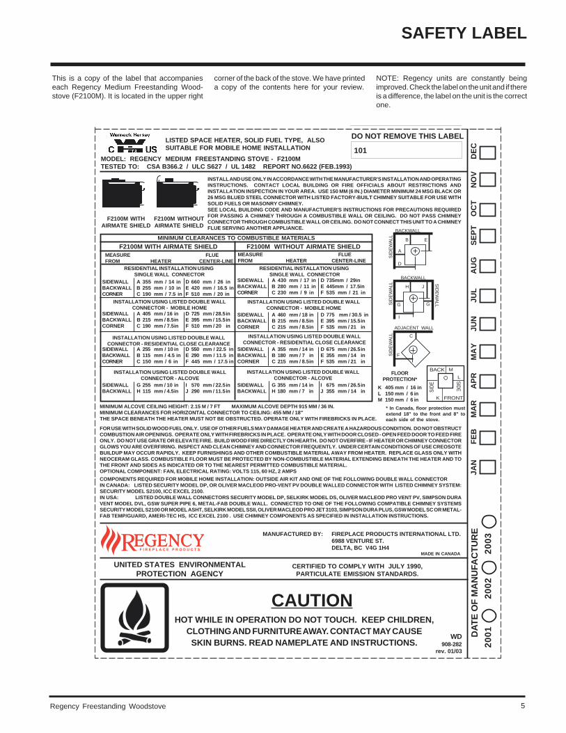
This is a copy of the label that accompanieseach Regency Medium Freestanding Wood-stove (F2100M). It is located in the upper right
SAFETY LABEL
NOTE: Regency units are constantly beingimproved. Check the label on the unit and if thereis a difference, the label on the unit is the correctone.
HOT WHILE IN OPERATION DO NOT TOUCH. KEEP CHILDREN,CLOTHING AND FURNITURE AWAY. CONTACT MAY CAUSESKIN BURNS. READ NAMEPLATE AND INSTRUCTIONS.
DO NOT REMOVE THIS LABEL
101
CERTIFIED TO COMPLY WITH JULY 1990,PARTICULATE EMISSION STANDARDS.
UNITED STATES ENVIRONMENTALPROTECTION AGENCY
MADE IN CANADA
JA
N F
EB
MA
R A
PR
MA
Y J
UN
JU
L A
UG
SE
PT
OC
T N
OV
DE
C
CAUTION
DA
TE
OF
MA
NU
FAC
TU
RE
WD908-282
rev. 01/03
LISTED SPACE HEATER, SOLID FUEL TYPE, ALSOSUITABLE FOR MOBILE HOME INSTALLATION
MODEL: REGENCY MEDIUM FREESTANDING STOVE - F2100MTESTED TO: CSA B366.2 / ULC S627 / UL 1482 REPORT NO.6622 (FEB.1993)
MINIMUM CLEARANCES TO COMBUSTIBLE MATERIALS
F2100M WITH AIRMATE SHIELD F2100M WITHOUT AIRMATE SHIELD
RESIDENTIAL INSTALLATION USING SINGLE WALL CONNECTOR
MEASURE FLUEFROM HEATER CENTER-LINE
RESIDENTIAL INSTALLATION USING SINGLE WALL CONNECTOR
SIDEWALL A 430 mm / 17 in D 735mm / 29inBACKWALL B 280 mm / 11 in E 445mm / 17.5inCORNER C 230 mm / 9 in F 535 mm / 21 in
INSTALLATION USING LISTED DOUBLE WALLCONNECTOR - MOBILE HOME
SIDEWALL A 460 mm / 18 in D 775 mm / 30.5 inBACKWALL B 215 mm / 8.5in E 395 mm / 15.5inCORNER C 215 mm / 8.5in F 535 mm / 21 in
INSTALLATION USING LISTED DOUBLE WALLCONNECTOR - RESIDENTIAL CLOSE CLEARANCE
SIDEWALL A 355 mm / 14 in D 675 mm / 26.5inBACKWALL B 180 mm / 7 in E 355 mm / 14 inCORNER C 215 mm / 8.5in F 535 mm / 21 in
INSTALLATION USING LISTED DOUBLE WALLCONNECTOR - ALCOVE
SIDEWALL A 355 mm / 14 in D 660 mm / 26 inBACKWALL B 255 mm / 10 in E 420 mm / 16.5 inCORNER C 190 mm / 7.5 in F 510 mm / 20 in
INSTALLATION USING LISTED DOUBLE WALLCONNECTOR - MOBILE HOME
SIDEWALL A 405 mm / 16 in D 725 mm / 28.5inBACKWALL B 215 mm / 8.5in E 395 mm / 15.5inCORNER C 190 mm / 7.5in F 510 mm / 20 in
SIDEWALL A 255 mm / 10 in D 550 mm / 22.5 inBACKWALL B 115 mm / 4.5 in E 290 mm / 11.5 inCORNER C 150 mm / 6 in F 445 mm / 17.5 in
INSTALLATION USING LISTED DOUBLE WALLCONNECTOR - RESIDENTIAL CLOSE CLEARANCE
INSTALLATION USING LISTED DOUBLE WALLCONNECTOR - ALCOVE
SIDEWALL G 355 mm / 14 in I 675 mm / 26.5inBACKWALL H 180 mm / 7 in J 355 mm / 14 in
MINIMUM ALCOVE CEILING HEIGHT: 2.15 M / 7 FT MAXIMUM ALCOVE DEPTH 915 MM / 36 IN.MINIMUM CLEARANCES FOR HORIZONTAL CONNECTOR TO CEILING: 455 MM / 18"THE SPACE BENEATH THE HEATER MUST NOT BE OBSTRUCTED. OPERATE ONLY WITH FIREBRICKS IN PLACE.
FLOORPROTECTION*
F2100M WITHOUTAIRMATE SHIELD
F2100M WITHAIRMATE SHIELD
INSTALL AND USE ONLY IN ACCORDANCE WITH THE MANUFACTURER'S INSTALLATION AND OPERATINGINSTRUCTIONS. CONTACT LOCAL BUILDING OR FIRE OFFICIALS ABOUT RESTRICTIONS ANDINSTALLATION INSPECTION IN YOUR AREA. USE 150 MM (6 IN.) DIAMETER MINIMUM 24 MSG BLACK OR26 MSG BLUED STEEL CONNECTOR WITH LISTED FACTORY-BUILT CHIMNEY SUITABLE FOR USE WITHSOLID FUELS OR MASONRY CHIMNEY.SEE LOCAL BUILDING CODE AND MANUFACTURER'S INSTRUCTIONS FOR PRECAUTIONS REQUIREDFOR PASSING A CHIMNEY THROUGH A COMBUSTIBLE WALL OR CEILING. DO NOT PASS CHIMNEYCONNECTOR THROUGH COMBUSTIBLE WALL OR CEILING. DO NOT CONNECT THIS UNIT TO A CHIMNEYFLUE SERVING ANOTHER APPLIANCE.
FRONT
BACK
L
K
M
SID
E
SIDEK 405 mm / 16 in
L 150 mm / 6 inM 150 mm / 6 in
FOR USE WITH SOLID WOOD FUEL ONLY. USE OF OTHER FUELS MAY DAMAGE HEATER AND CREATE A HAZARDOUS CONDITION. DO NOT OBSTRUCTCOMBUSTION AIR OPENINGS. OPERATE ONLY WITH FIREBRICKS IN PLACE. OPERATE ONLY WITH DOOR CLOSED - OPEN FEED DOOR TO FEED FIREONLY. DO NOT USE GRATE OR ELEVATE FIRE. BUILD WOOD FIRE DIRECTLY ON HEARTH. DO NOT OVERFIRE - IF HEATER OR CHIMNEY CONNECTORGLOWS YOU ARE OVERFIRING. INSPECT AND CLEAN CHIMNEY AND CONNECTOR FREQUENTLY. UNDER CERTAIN CONDITIONS OF USE CREOSOTEBUILDUP MAY OCCUR RAPIDLY. KEEP FURNISHINGS AND OTHER COMBUSTIBLE MATERIAL AWAY FROM HEATER. REPLACE GLASS ONLY WITHNEOCERAM GLASS. COMBUSTIBLE FLOOR MUST BE PROTECTED BY NON-COMBUSTIBLE MATERIAL EXTENDING BENEATH THE HEATER AND TOTHE FRONT AND SIDES AS INDICATED OR TO THE NEAREST PERMITTED COMBUSTIBLE MATERIAL.OPTIONAL COMPONENT: FAN, ELECTRICAL RATING: VOLTS 115, 60 HZ, 2 AMPS
COMPONENTS REQUIRED FOR MOBILE HOME INSTALLATION: OUTSIDE AIR KIT AND ONE OF THE FOLLOWING DOUBLE WALL CONNECTORIN CANADA: LISTED SECURITY MODEL DP, OR OLIVER MACLEOD PRO-VENT PV DOUBLE WALLED CONNECTOR WITH LISTED CHIMNEY SYSTEM:SECURITY MODEL S2100, ICC EXCEL 2100.IN USA: LISTED DOUBLE WALL CONNECTORS SECURITY MODEL DP, SELKIRK MODEL DS, OLIVER MACLEOD PRO VENT PV, SIMPSON DURAVENT MODEL DVL, GSW SUPER PIPE 6, METAL-FAB DOUBLE WALL. CONNECTED TO ONE OF THE FOLLOWING COMPATIBLE CHIMNEY SYSTEMSSECURITY MODEL S2100 OR MODEL ASHT, SELKIRK MODEL SSII, OLIVER MACLEOD PRO JET 3103, SIMPSON DURA PLUS, GSW MODEL SC OR METAL-FAB TEMP/GUARD, AMERI-TEC HS, ICC EXCEL 2100 . USE CHIMNEY COMPONENTS AS SPECIFIED IN INSTALLATION INSTRUCTIONS.
MEASURE FLUEFROM HEATER CENTER-LINE
A
D
BACKWALL
SID
EW
ALL B E
G G
I
BACKWALL
SID
EW
ALL
SID
EW
ALL
H J
F
ADJACENT WALL
SID
EW
ALL C
MANUFACTURED BY: FIREPLACE PRODUCTS INTERNATIONAL LTD.6988 VENTURE ST.DELTA, BC V4G 1H4
SIDEWALL G 255 mm / 10 in I 570 mm / 22.5inBACKWALL H 115 mm / 4.5in J 290 mm / 11.5in
20
01
20
03
20
02
* In Canada, floor protection mustextend 18" to the front and 8" toeach side of the stove.
corner of the back of the stove. We have printeda copy of the contents here for your review.
Regency Freestanding Woodstove6
UNITED STATES ENVIRONMENTALPROTECTION AGENCY
F3100L WITHAIRMATE SHIELD
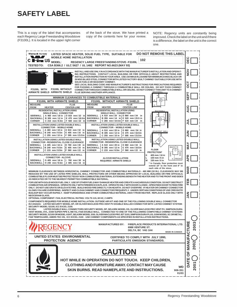
MINIMUM CLEARANCES TO COMBUSTIBLE MATERIALS
F3100L WITH AIRMATE SHIELD
RESIDENTIAL INSTALLATION USING SINGLE WALL CONNECTOR
SIDEWALL A 460 mm / 18 in D 810 mm / 32 inBACKWALL B 305 mm / 12 in E 470 mm / 18.5inCORNER C 215 mm / 8.5in F 560 mm / 22 in
INSTALLATION USING LISTED DOUBLE WALLCONNECTOR - MOBILE HOME
SIDEWALL A 460 mm / 18 in D 810 mm / 32 inBACKWALL B 240 mm / 9.5in E 405 mm / 16 inCORNER C 255 mm / 10 in F 595 mm / 23.5in
INSTALLATION USING LISTED DOUBLE WALLCONNECTOR - RESIDENTIAL CLOSE CLEARANCE
SIDEWALL A 405 mm / 16 in D 760 mm / 30 inBACKWALL B 240 mm / 9.5in E 405 mm / 16 inCORNER C 215 mm / 8.5in F 560 mm / 22 in
SIDEWALL G 405 mm / 16 in I 760 mm / 30 inBACKWALL H 240 mm / 9.5in J 405 mm / 16 in
MEASURE FLUEFROM HEATER CENTER-LINE
COMPONENTS REQUIRED FOR MOBILE HOME INSTALLATION: OUTSIDE AIR KIT AND ONE OF THE FOLLOWING DOUBLE WALL CONNECTORIN CANADA: LISTED SECURITY MODEL DP, OR OLIVER MACLEOD PRO-VENT PV DOUBLE WALLED CONNECTOR WITH LISTED CHIMNEY SYSTEM:SECURITY MODEL S2100, ICC EXCEL 2100.IN USA: LISTED DOUBLE WALL CONNECTORS SECURITY MODEL DP, SELKIRK MODEL DS, OLIVER MACLEOD PRO VENT PV, SIMPSON DURAVENT MODEL DVL, GSW SUPER PIPE 6, METAL-FAB DOUBLE WALL. CONNECTED TO ONE OF THE FOLLOWING COMPATIBLE CHIMNEY SYSTEMSSECURITY MODEL S2100 OR MODEL ASHT, SELKIRK MODEL SSII, OLIVER MACLEOD PRO JET 3103, SIMPSON DURA PLUS, GSW MODEL SC OR METAL-FAB TEMP/GUARD, AMERI-TEC HS, ICC EXCEL 2100 . USE CHIMNEY COMPONENTS AS SPECIFIED IN INSTALLATION INSTRUCTIONS.
MINIMUM CLEARANCE BETWEEN HORIZONTAL CHIMNEY CONNECTOR AND COMBUSTIBLE MATERIALS - 460 MM (18 IN.). CLEARANCE MAY BEREDUCED BY THE USE OF LISTED PIPE SHIELDS, WALL PROTECTORS OR OTHER MEANS APPROVED BY LOCAL BUILDING OR FIRE OFFICIALS.COMBUSTIBLE FLOOR MUST BE PROTECTED BY NON-COMBUSTIBLE MATERIAL EXTENDING BENEATH THE HEATER AND TO THE FRONT AND SIDESAS INDICATED OR TO THE NEAREST PERMITTED COMBUSTIBLE MATERIAL.
FOR USE WITH SOLID WOOD FUEL ONLY. USE OF OTHER FUELS MAY DAMAGE HEATER AND CREATE A HAZARDOUS CONDITION. DO NOT OBSTRUCTCOMBUSTION AIR OPENINGS. OPERATE ONLY WITH FIREBRICKS IN PLACE. OPERATE ONLY WITH DOOR CLOSED - OPEN FEED DOOR TO FEED FIREONLY. DO NOT USE GRATE OR ELEVATE FIRE. BUILD WOOD FIRE DIRECTLY ON HEARTH. DO NOT OVERFIRE - IF HEATER OR CHIMNEY CONNECTORGLOWS YOU ARE OVERFIRING. INSPECT AND CLEAN CHIMNEY AND CONNECTOR FREQUENTLY. UNDER CERTAIN CONDITIONS OF USE CREOSOTEBUILDUP MAY OCCUR RAPIDLY. KEEP FURNISHINGS AND OTHER COMBUSTIBLE MATERIAL AWAY FROM HEATER. REPLACE GLASS ONLY WITHNEOCERAM GLASS.OPTIONAL COMPONENT: FAN, ELECTRICAL RATING: VOLTS 115, 60 HZ, 2 AMPS
INSTALLATION USING LISTED DOUBLE WALLCONNECTOR - ALCOVE
HOT WHILE IN OPERATION DO NOT TOUCH. KEEP CHILDREN,CLOTHING AND FURNITURE AWAY. CONTACT MAY CAUSESKIN BURNS. READ NAMEPLATE AND INSTRUCTIONS.
DO NOT REMOVE THIS LABEL
102
CERTIFIED TO COMPLY WITH JULY 1990,PARTICULATE EMISSION STANDARDS.
MADE IN CANADA
JA
N F
EB
MA
R A
PR
MA
Y J
UN
JU
L A
UG
SE
PT
OC
T N
OV
DE
C
CAUTION
DA
TE
OF
MA
NU
FAC
TU
RE
20
01
20
03
20
02
WD908-351
01/03
A
D
BACKWALL
SID
EW
ALL B E
G G
I
BACKWALL
SID
EW
ALL
SID
EW
ALL
H J
F
ADJACENT WALL
SID
EW
ALL C
INSTALL AND USE ONLY IN ACCORDANCE WITH THE MANUFACTURER'S INSTALLATION AND OPERAT-ING INSTRUCTIONS. CONTACT LOCAL BUILDING OR FIRE OFFICIALS ABOUT RESTRICTIONS ANDINSTALLATION INSPECTION IN YOUR AREA. USE 150 MM (6 IN.) DIAMETER MINIMUM 24 MSG BLACK OR26 MSG BLUED STEEL CONNECTOR WITH LISTED FACTORY-BUILT CHIMNEY SUITABLE FOR USE WITHSOLID FUELS OR MASONRY CHIMNEY.SEE LOCAL BUILDING CODE AND MANUFACTURER'S INSTRUCTIONS FOR PRECAUTIONS REQUIREDFOR PASSING A CHIMNEY THROUGH A COMBUSTIBLE WALL OR CEILING. DO NOT PASS CHIMNEYCONNECTOR THROUGH COMBUSTIBLE WALL OR CEILING. DO NOT CONNECT THIS UNIT TO A CHIMNEYFLUE SERVING ANOTHER APPLIANCE.
F3100L WITHOUTAIRMATE SHIELD
F3100L WITHOUT AIRMATE SHIELDMEASURE FLUEFROM HEATER CENTER-LINE
RESIDENTIAL INSTALLATION USING SINGLE WALL CONNECTOR
SIDEWALL A 510 mm / 20 in D 860 mm / 34 inBACKWALL B 355 mm / 14 in E 520 mm / 20.5 inCORNER C 265 mm / 10.5in F 610 mm / 24 in
INSTALLATION USING LISTED DOUBLE WALLCONNECTOR - MOBILE HOME
SIDEWALL A 510 mm / 20 in D 860 mm / 34 inBACKWALL B 305 mm / 12 in E 470 mm / 18.5inCORNER C 255 mm / 10 in F 595 mm / 23.5in
INSTALLATION USING LISTED DOUBLE WALLCONNECTOR - RESIDENTIAL CLOSE CLEARANCE
SIDEWALL A 510 mm / 20 in D 860 mm / 34 inBACKWALL B 305 mm / 12 in E 470 mm / 18.5inCORNER C 215 mm / 8.5in F 560 mm / 22 in
ALCOVE INSTALLATIONREQUIRES AIRMATE SHIELD
FLOORPROTECTION*
K 405 mm / 16 inL 150 mm / 6 inM 150 mm / 6 in
LISTED SPACE HEATER, SOLID FUEL TYPE, SUITABLE FORMOBILE HOME INSTALLATION
MODEL: REGENCY LARGE FREESTANDING STOVE - F3100L
MANUFACTURED BY: FIREPLACE PRODUCTS INTERNATIONAL LTD.6988 VENTURE ST.DELTA, BC V4G 1H4
FRONT
BACK
L
K
M
SID
E
SID
E
TESTED TO: CSA B366.2 / ULC S627 / UL 1482 REPORT NO.6623 (MAY 93)
* In Canada, floor protection mustextend 18" to the front and 8" toeach side of the stove.
This is a copy of the label that accompanieseach Regency Large Freestanding Woodstove(F3100L). It is located in the upper right corner
of the back of the stove. We have printed acopy of the contents here for your review.
SAFETY LABEL
NOTE: Regency units are constantly beingimproved. Check the label on the unit and if thereis a difference, the label on the unit is the correctone.
Regency Freestanding Woodstove 7
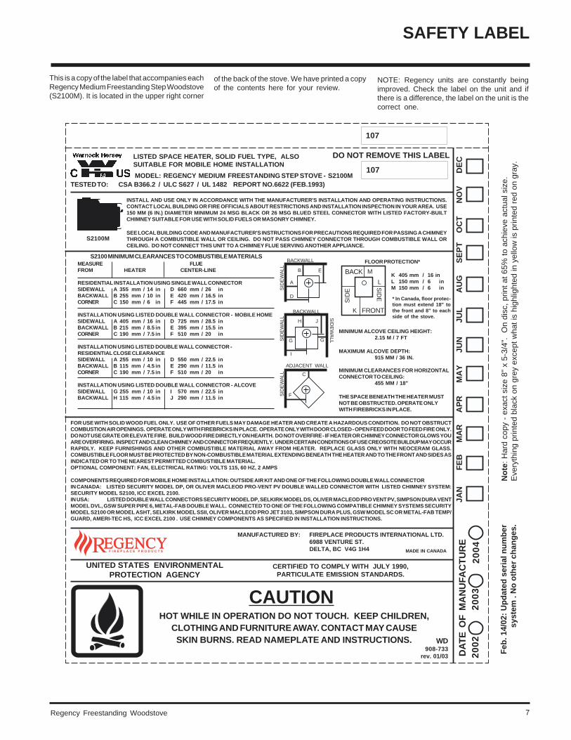
This is a copy of the label that accompanies eachRegency Medium Freestanding Step Woodstove(S2100M). It is located in the upper right corner
of the back of the stove. We have printed a copyof the contents here for your review.
SAFETY LABEL
NOTE: Regency units are constantly beingimproved. Check the label on the unit and ifthere is a difference, the label on the unit is thecorrect one.
HOT WHILE IN OPERATION DO NOT TOUCH. KEEP CHILDREN,CLOTHING AND FURNITURE AWAY. CONTACT MAY CAUSESKIN BURNS. READ NAMEPLATE AND INSTRUCTIONS.
DO NOT REMOVE THIS LABEL
107
CERTIFIED TO COMPLY WITH JULY 1990,PARTICULATE EMISSION STANDARDS.
UNITED STATES ENVIRONMENTALPROTECTION AGENCY
MADE IN CANADA
JA
N F
EB
MA
R A
PR
MA
Y J
UN
JU
L A
UG
SE
PT
OC
T N
OV
DE
C
CAUTION
DA
TE
OF
MA
NU
FAC
TU
RE
20
02
20
04
20
03
WD908-733
rev. 01/03
LISTED SPACE HEATER, SOLID FUEL TYPE, ALSOSUITABLE FOR MOBILE HOME INSTALLATION
MODEL: REGENCY MEDIUM FREESTANDING STEP STOVE - S2100M
S2100 MINIMUM CLEARANCES TO COMBUSTIBLE MATERIALSMEASURE FLUEFROM HEATER CENTER-LINE
RESIDENTIAL INSTALLATION USING SINGLE WALL CONNECTORSIDEWALL A 355 mm / 14 in D 660 mm / 26 inBACKWALL B 255 mm / 10 in E 420 mm / 16.5 inCORNER C 150 mm / 6 in F 445 mm / 17.5 in
INSTALLATION USING LISTED DOUBLE WALL CONNECTOR - MOBILE HOMESIDEWALL A 405 mm / 16 in D 725 mm / 28.5 inBACKWALL B 215 mm / 8.5 in E 395 mm / 15.5 inCORNER C 190 mm / 7.5 in F 510 mm / 20 in
INSTALLATION USING LISTED DOUBLE WALL CONNECTOR -RESIDENTIAL CLOSE CLEARANCESIDEWALL A 255 mm / 10 in D 550 mm / 22.5 inBACKWALL B 115 mm / 4.5 in E 290 mm / 11.5 inCORNER C 190 mm / 7.5 in F 510 mm / 20 in
INSTALLATION USING LISTED DOUBLE WALL CONNECTOR - ALCOVESIDEWALL G 255 mm / 10 in I 570 mm / 22.5 inBACKWALL H 115 mm / 4.5 in J 290 mm / 11.5 in
FOR USE WITH SOLID WOOD FUEL ONLY. USE OF OTHER FUELS MAY DAMAGE HEATER AND CREATE A HAZARDOUS CONDITION. DO NOT OBSTRUCTCOMBUSTION AIR OPENINGS. OPERATE ONLY WITH FIREBRICKS IN PLACE. OPERATE ONLY WITH DOOR CLOSED - OPEN FEED DOOR TO FEED FIRE ONLY.DO NOT USE GRATE OR ELEVATE FIRE. BUILD WOOD FIRE DIRECTLY ON HEARTH. DO NOT OVERFIRE - IF HEATER OR CHIMNEY CONNECTOR GLOWS YOUARE OVERFIRING. INSPECT AND CLEAN CHIMNEY AND CONNECTOR FREQUENTLY. UNDER CERTAIN CONDITIONS OF USE CREOSOTE BUILDUP MAY OCCURRAPIDLY. KEEP FURNISHINGS AND OTHER COMBUSTIBLE MATERIAL AWAY FROM HEATER. REPLACE GLASS ONLY WITH NEOCERAM GLASS.COMBUSTIBLE FLOOR MUST BE PROTECTED BY NON-COMBUSTIBLE MATERIAL EXTENDING BENEATH THE HEATER AND TO THE FRONT AND SIDES ASINDICATED OR TO THE NEAREST PERMITTED COMBUSTIBLE MATERIAL.OPTIONAL COMPONENT: FAN, ELECTRICAL RATING: VOLTS 115, 60 HZ, 2 AMPS
COMPONENTS REQUIRED FOR MOBILE HOME INSTALLATION: OUTSIDE AIR KIT AND ONE OF THE FOLLOWING DOUBLE WALL CONNECTORIN CANADA: LISTED SECURITY MODEL DP, OR OLIVER MACLEOD PRO-VENT PV DOUBLE WALLED CONNECTOR WITH LISTED CHIMNEY SYSTEM:SECURITY MODEL S2100, ICC EXCEL 2100.IN USA: LISTED DOUBLE WALL CONNECTORS SECURITY MODEL DP, SELKIRK MODEL DS, OLIVER MACLEOD PRO VENT PV, SIMPSON DURA VENTMODEL DVL, GSW SUPER PIPE 6, METAL-FAB DOUBLE WALL. CONNECTED TO ONE OF THE FOLLOWING COMPATIBLE CHIMNEY SYSTEMS SECURITYMODEL S2100 OR MODEL ASHT, SELKIRK MODEL SSII, OLIVER MACLEOD PRO JET 3103, SIMPSON DURA PLUS, GSW MODEL SC OR METAL-FAB TEMP/GUARD, AMERI-TEC HS, ICC EXCEL 2100 . USE CHIMNEY COMPONENTS AS SPECIFIED IN INSTALLATION INSTRUCTIONS.
FLOOR PROTECTION*
S2100M
INSTALL AND USE ONLY IN ACCORDANCE WITH THE MANUFACTURER'S INSTALLATION AND OPERATING INSTRUCTIONS.CONTACT LOCAL BUILDING OR FIRE OFFICIALS ABOUT RESTRICTIONS AND INSTALLATION INSPECTION IN YOUR AREA. USE150 MM (6 IN.) DIAMETER MINIMUM 24 MSG BLACK OR 26 MSG BLUED STEEL CONNECTOR WITH LISTED FACTORY-BUILTCHIMNEY SUITABLE FOR USE WITH SOLID FUELS OR MASONRY CHIMNEY.
SEE LOCAL BUILDING CODE AND MANUFACTURER'S INSTRUCTIONS FOR PRECAUTIONS REQUIRED FOR PASSING A CHIMNEYTHROUGH A COMBUSTIBLE WALL OR CEILING. DO NOT PASS CHIMNEY CONNECTOR THROUGH COMBUSTIBLE WALL ORCEILING. DO NOT CONNECT THIS UNIT TO A CHIMNEY FLUE SERVING ANOTHER APPLIANCE.
FRONT
BACK
L
K
M
SID
E
SID
E
K 405 mm / 16 inL 150 mm / 6 inM 150 mm / 6 in
A
D
BACKWALL
SID
EW
ALL B E
G G
I
BACKWALL
SID
EW
ALL
SID
EW
ALL
H J
F
ADJACENT WALL
SID
EW
ALL C
Feb
. 14/
02:
Up
dat
ed s
eria
l nu
mb
ersy
stem
. N
o o
ther
ch
ang
es.
MANUFACTURED BY: FIREPLACE PRODUCTS INTERNATIONAL LTD.6988 VENTURE ST.DELTA, BC V4G 1H4
No
te: H
ard
copy
- e
xact
siz
e 8"
x 5
-3/4
".
On
disc
, prin
t at 6
5% to
ach
ieve
act
ual s
ize.
Eve
ryth
ing
prin
ted
blac
k on
gre
y ex
cept
wha
t is
high
light
ed in
yel
low
is p
rinte
d re
d on
gra
y.
107
TESTED TO: CSA B366.2 / ULC S627 / UL 1482 REPORT NO.6622 (FEB.1993)
MINIMUM ALCOVE CEILING HEIGHT:2.15 M / 7 FT
MAXIMUM ALCOVE DEPTH:915 MM / 36 IN.
MINIMUM CLEARANCES FOR HORIZONTALCONNECTOR TO CEILING:
455 MM / 18"
THE SPACE BENEATH THE HEATER MUSTNOT BE OBSTRUCTED. OPERATE ONLYWITH FIREBRICKS IN PLACE.
* In Canada, floor protec-tion must extend 18" tothe front and 8" to eachside of the stove.
Regency Freestanding Woodstove8
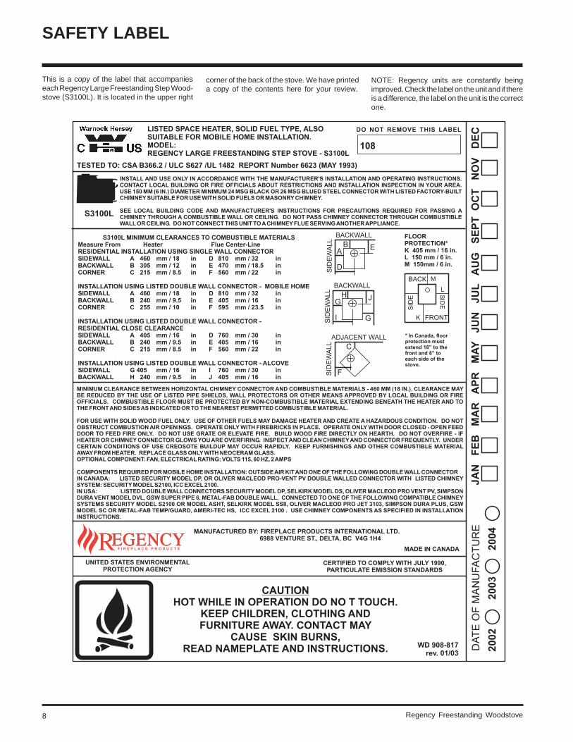
This is a copy of the label that accompanieseach Regency Large Freestanding Step Wood-stove (S3100L). It is located in the upper right
corner of the back of the stove. We have printeda copy of the contents here for your review.
SAFETY LABEL
NOTE: Regency units are constantly beingimproved. Check the label on the unit and if thereis a difference, the label on the unit is the correctone.
Regency Freestanding Woodstove 9
INSTALLATION
RESIDENTIALINSTALLATION
1) Read all instructions before installing yourRegency Stove. Install and use only inaccordance with these installation andoperating instructions. Be aware that localCodes and Regulations may override someitems in this manual. Check with your localinspector.
2) Select a position for your Regency Stove.Consult the minimum clearance chart foryour model and set the stove in place. Forclose clearance installation use listed dou-ble wall connector systems (see page 15).
3) To insure vertical alignment, suspend aplumb bob from the ceiling over the exactcenter of your stove flue and mark a spot onthe ceiling to indicate the center of thechimney.
4) Check that the area above the ceiling is clearfor cutting. Re-confirm the clearance fromthe stove to combustibles to insure that theyare within the prescribed limits.
5) Install chimney according to chimney man-ufacturers instructions. The performanceof your woodstove is governed to a verylarge part by the chimney system. Too shorta chimney can cause difficult start-up, dirtyglass, backsmoking when door is open, andeven reduced heat output. Too tall a chim-ney may prompt excessive draft which canresult in very short burn times and exces-sive heat output. The use of an inexpensiveflue pipe damper may be helpful in reducingexcessive draft.
CAUTION: The chimney should be the samesize as the flue outlet on the stove. The
chimney must be listed as suitable for usewith solid fuels. For other types of chim-neys check with your local building codeofficials. Do not confuse a chimney with atype “B” Venting System used for gasappliances as suitable for a wood burningappliance. For Mobile Home installationsrefer to that section on page 14.
6) Mark the location of the pedestal base orlegs on the floor, then move the stove asideand mark the position of the floor protector.
7) The floor protector must be of non-combus-tible material and must extend 16" in front ofthe door opening and 6" to the sides andrear of the unit. Some areas may require alarger size floor protector. See your localinspector. For outside air installation referto Mobile Home installation instructions onpage 14.
8) When the floor protection is complete, po-sition the stove with the flue collar centeredunder the installed chimney.
9) In seismically active areas, Regency rec-ommends that your unit is secured to thefloor by using the bolt down holes inside thepedestal (the same ones used in MobileHome installations).
10) For residential installations using "C" Vent(single wall) the chimney connector mustbe at least 24 gauge steel. Do not usegalvanized pipe. For Mobile Home installa-tion refer to the Mobile Home installationinstructions on page 14.
11) Do not connect this unit to a chimney serv-ing another appliance unless approved by
your local building authority.
12) A chimney connector cannot pass throughan attic or roof space, closet or similarconcealed space, or a floor, ceiling, wall orpartition of combustible construction. InCanada, if passage through a wall, or par-tition of combustible construction is de-sired, the installation shall conform to CAN/CSA-B365, Installation Code for Solid-Fuel-Burning Appliances and Equipment.
13) Your Regency Woodstove is not to beconnected to any air distribution duct.
ROOM AIRIMPORTANT
For installation using room air for combustion,remove knockout from the pedestal, and/orfrom the bottom if using a heat shield.
Mobile home installations require the use ofoutside air.
On pedestal units there are two locations whereoutside air may be adapted to the unit. If usingthe bottom of the pedestal, do not removeknockout from the rear of the pedestal. Onlyremove rear knockout if outside air will bebrought in from the rear.
On leg units outside air can only be brought infrom the bottom of the heat shield.Note: Once the knockout is removed
there are two tabs remaining. Bendboth tabs out for ease of installa-tion when attaching outside air.
MODULAR INSTALLATION OPTIONS
Modular Part Things to consider when choosing options:
Modular Option
Blower/Fan
Ash Drawer Kit
OPTIONS: These can be installed at time of installation or added later:
F1100, F2100 andF3100 only:Airmate OR
Rear Heat Deflector
(all units)Pedestal OR
Legs
Things to consider when choosing options
The following items are required when assembling your Regency Stove. F1100, F2100, and F3100 units - the Rear Heat Deflector is supplied withthe stove, but if you choose not to use it you must use the Airmate instead.
Clearances are different. See the chart on pages 10 and 11. Generally you can get closer clearances with the airmatethan with the rear heat deflector.
Convection heat with Airmate vs. Radiant Heat with Rear Heat Deflector. The airmate pushes heat forward and intothe room, the rear heat deflector deflects the heat upward. See installation instructions on pages 11 and 12.
There are no performance differences with either the pedestal or legs. It is primarily a personal preference. Legscan be either painted steel, painted cast, or gold plated cast.
Leg installation requires the bottom shield. See installation instructions on page 13.
Adding the blower will increase the area heated by the stove, it can move warm air beyond the room where the stoveis installed. Installation instructions on page 18.
Adding the Ash Drawer Kit makes cleaning ashes out of the stove easier and cleaner. Installation instructions on page17.
Emissions from burning wood or gas couldcontain chemicals known to the State ofCalifornia to cause cancer, birth defects orother reproductive harm.
NOTE: In Canada, floor protection mustextend 18" to the front and 8" toeach side of the stove.
Regency Freestanding Woodstove10
INSTALLATION
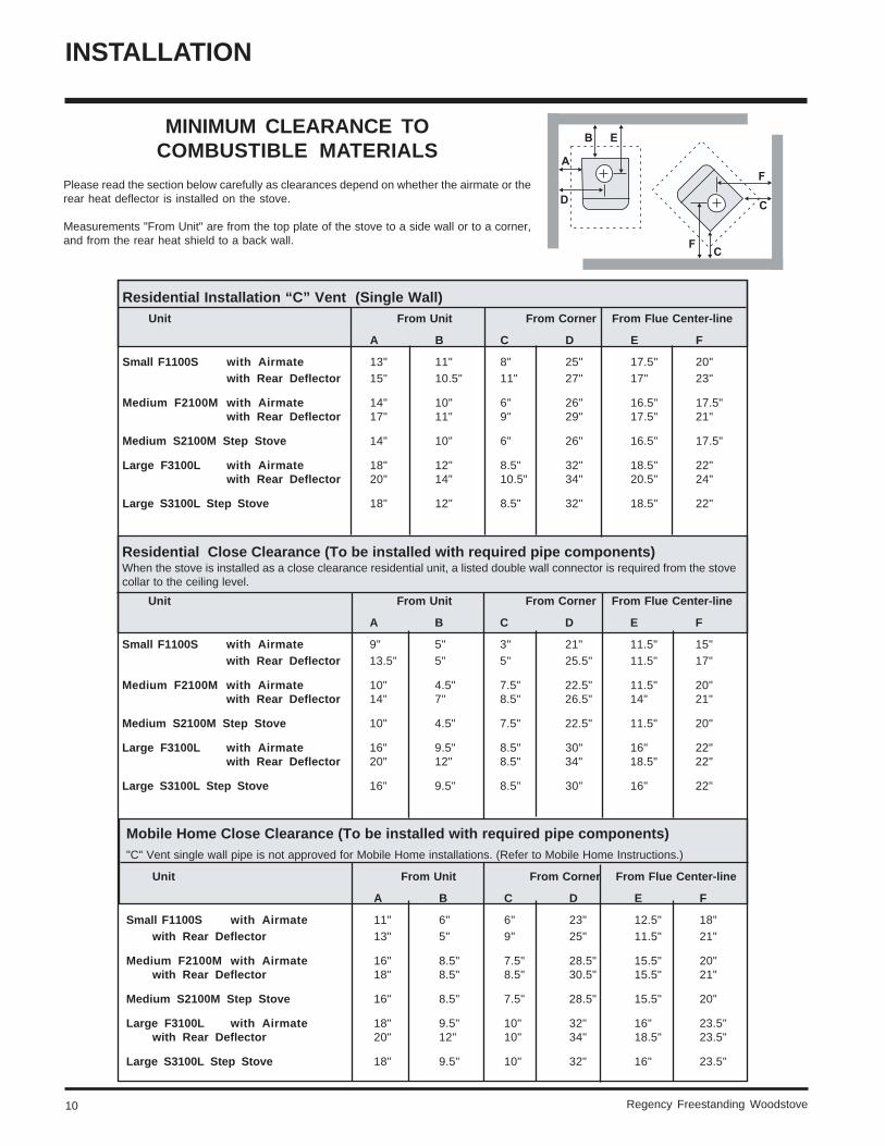
MINIMUM CLEARANCE TOCOMBUSTIBLE MATERIALS
Please read the section below carefully as clearances depend on whether the airmate or therear heat deflector is installed on the stove.
Measurements "From Unit" are from the top plate of the stove to a side wall or to a corner,and from the rear heat shield to a back wall.
Residential Installation “C” Vent (Single Wall)Unit From Unit From Corner From Flue Center-line
A B C D E F
Small F1100S with Airmate 13" 11" 8" 25" 17.5" 20"with Rear Deflector 15" 10.5" 11" 27" 17" 23"
Medium F2100M with Airmate 14" 10" 6" 26" 16.5" 17.5"with Rear Deflector 17" 11" 9" 29" 17.5" 21"
Medium S2100M Step Stove 14" 10" 6" 26" 16.5" 17.5"
Large F3100L with Airmate 18" 12" 8.5" 32" 18.5" 22"with Rear Deflector 20" 14" 10.5" 34" 20.5" 24"
Large S3100L Step Stove 18" 12" 8.5" 32" 18.5" 22"
Residential Close Clearance (To be installed with required pipe components)When the stove is installed as a close clearance residential unit, a listed double wall connector is required from the stovecollar to the ceiling level.
Unit From Unit From Corner From Flue Center-line
A B C D E F
Small F1100S with Airmate 9" 5" 3" 21" 11.5" 15"with Rear Deflector 13.5" 5" 5" 25.5" 11.5" 17"
Medium F2100M with Airmate 10" 4.5" 7.5" 22.5" 11.5" 20"with Rear Deflector 14" 7" 8.5" 26.5" 14" 21"
Medium S2100M Step Stove 10" 4.5" 7.5" 22.5" 11.5" 20"
Large F3100L with Airmate 16" 9.5" 8.5" 30" 16" 22"with Rear Deflector 20" 12" 8.5" 34" 18.5" 22"
Large S3100L Step Stove 16" 9.5" 8.5" 30" 16" 22"
Mobile Home Close Clearance (To be installed with required pipe components)"C" Vent single wall pipe is not approved for Mobile Home installations. (Refer to Mobile Home Instructions.)
Unit From Unit From Corner From Flue Center-line
A B C D E F
Small F1100S with Airmate 11" 6" 6" 23" 12.5" 18"with Rear Deflector 13" 5" 9" 25" 11.5" 21"
Medium F2100M with Airmate 16" 8.5" 7.5" 28.5" 15.5" 20"with Rear Deflector 18" 8.5" 8.5" 30.5" 15.5" 21"
Medium S2100M Step Stove 16" 8.5" 7.5" 28.5" 15.5" 20"
Large F3100L with Airmate 18" 9.5" 10" 32" 16" 23.5"with Rear Deflector 20" 12" 10" 34" 18.5" 23.5"
Large S3100L Step Stove 18" 9.5" 10" 32" 16" 23.5"
Regency Freestanding Woodstove 11
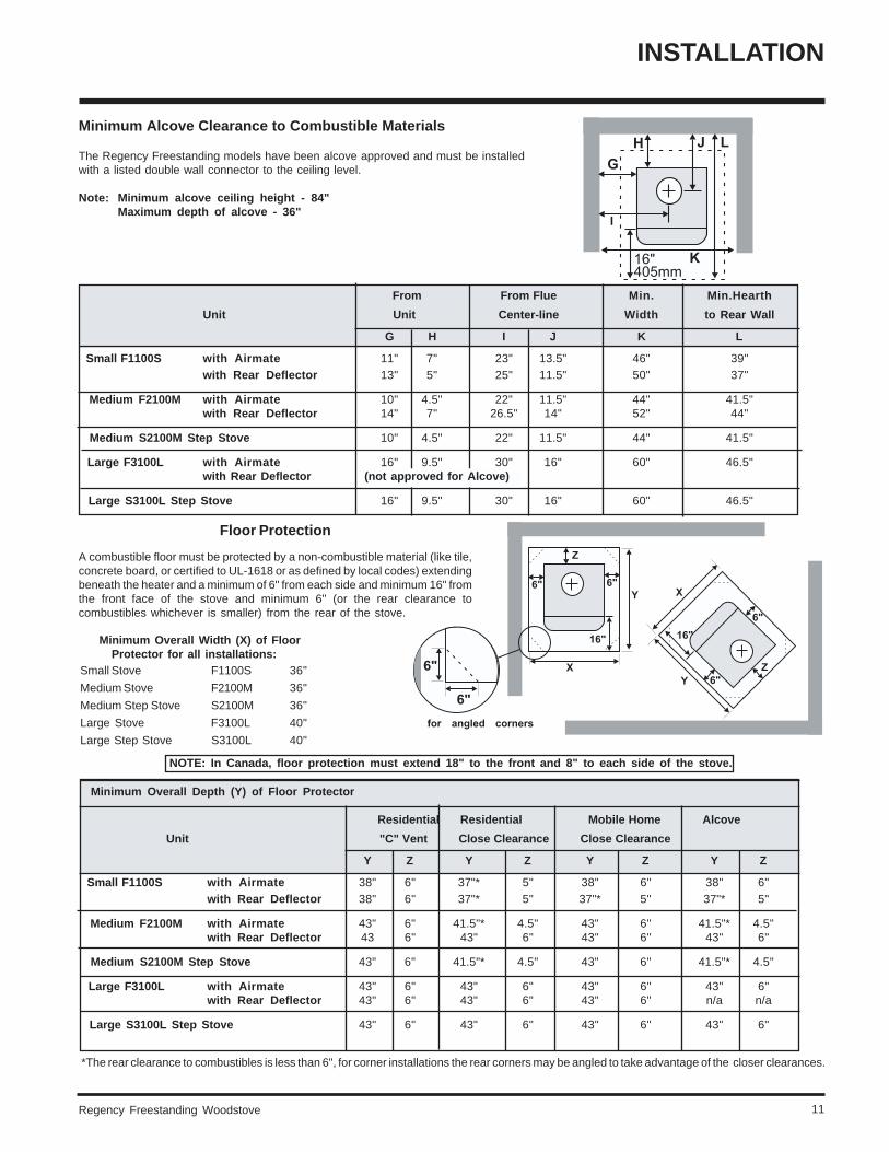
Minimum Alcove Clearance to Combustible Materials
The Regency Freestanding models have been alcove approved and must be installedwith a listed double wall connector to the ceiling level.
Note: Minimum alcove ceiling height - 84"Maximum depth of alcove - 36"
Minimum Overall Width (X) of Floor Protector for all installations:Small Stove F1100S 36"
Medium Stove F2100M 36"
Medium Step Stove S2100M 36"
Large Stove F3100L 40"
Large Step Stove S3100L 40"
Minimum Overall Depth (Y) of Floor Protector
Residential Residential Mobile Home Alcove
Unit "C" Vent Close Clearance Close Clearance
Y Z Y Z Y Z Y Z
Small F1100S with Airmate 38" 6" 37"* 5" 38" 6" 38" 6"with Rear Deflector 38" 6" 37"* 5" 37"* 5" 37"* 5"
Medium F2100M with Airmate 43" 6" 41.5"* 4.5" 43" 6" 41.5"* 4.5"with Rear Deflector 43 6" 43" 6" 43" 6" 43" 6"
Medium S2100M Step Stove 43" 6" 41.5"* 4.5" 43" 6" 41.5"* 4.5"
Large F3100L with Airmate 43" 6" 43" 6" 43" 6" 43" 6"with Rear Deflector 43" 6" 43" 6" 43" 6" n/a n/a
Large S3100L Step Stove 43" 6" 43" 6" 43" 6" 43" 6"
INSTALLATION
From From Flue Min. Min.Hearth
Unit Unit Center-line Width to Rear Wall
G H I J K L
Small F1100S with Airmate 11" 7" 23" 13.5" 46" 39"with Rear Deflector 13" 5" 25" 11.5" 50" 37"
Medium F2100M with Airmate 10" 4.5" 22" 11.5" 44" 41.5"with Rear Deflector 14" 7" 26.5" 14" 52" 44"
Medium S2100M Step Stove 10" 4.5" 22" 11.5" 44" 41.5"
Large F3100L with Airmate 16" 9.5" 30" 16" 60" 46.5"with Rear Deflector (not approved for Alcove)
Large S3100L Step Stove 16" 9.5" 30" 16" 60" 46.5"
*The rear clearance to combustibles is less than 6", for corner installations the rear corners may be angled to take advantage of the closer clearances.
Floor Protection
A combustible floor must be protected by a non-combustible material (like tile,concrete board, or certified to UL-1618 or as defined by local codes) extendingbeneath the heater and a minimum of 6" from each side and minimum 16" fromthe front face of the stove and minimum 6" (or the rear clearance tocombustibles whichever is smaller) from the rear of the stove.
NOTE: In Canada, floor protection must extend 18" to the front and 8" to each side of the stove.
Regency Freestanding Woodstove12
INSTALLATION
Diagram 4
Diagram 2
Diagram 3
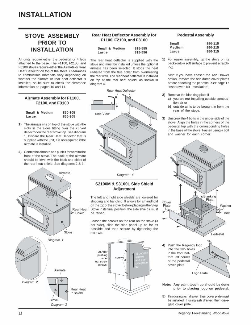
STOVE ASSEMBLYPRIOR TO
INSTALLATION
All units require either the pedestal or 4 legsattached to the base. The F1100, F2100, andF3100 stoves require either the Airmate or RearHeat Deflector on top of the stove. Clearancesto combustible materials vary depending onwhether the airmate or rear heat deflector isinstalled, so be sure to check the clearanceinformation on pages 10 and 11.
Airmate Assembly for F1100,F2100, and F3100
Small & Medium 850-105Large 850-305
1) The airmate sits on top of the stove with theslots in the sides fitting over the curveddeflector on the rear stove top. See diagram1. Discard the Rear Heat Deflector that issupplied with the unit, it is not required if theairmate is installed.
2) Center the airmate and push it forward to thefront of the stove. The back of the airmateshould be level with the back and sides ofthe rear heat shield. See diagrams 2 & 3.
Diagram 1
Rear Heat Deflector Assembly forF1100, F2100, and F3100
Small & Medium 815-555Large 815-556
The rear heat deflector is supplied with thestove and must be installed unless the optionalairmate has been selected. It stops the heatradiated from the flue collar from overheatingthe rear wall. The rear heat deflector is installedon top of the rear heat shield, as shown indiagram 4.
S2100M & S3100L Side ShieldAdjustment
The left and right side shields are lowered forshipping and handling. It allows for a handholdon the top of the stove. Before placing in the StepStove in its final position, the side shields mustbe raised.
Loosen the screws on the rear on the stove (3per side), slide the side panel up as far aspossible and then secure by tightening thescrews.
Pedestal Assembly
Small 850-115Medium 850-215Large 850-315
1) For easier assembly, tip the stove on itsback (onto a soft surface to prevent scratch-ing).
Hint: If you have chosen the Ash Draweroption, remove the ash dump cover platesbefore attaching the pedestal. See page 17"Ashdrawer Kit Installation".
2) Remove the blanking plate ifa) you are not installing outside combus-
tion air orb) outside air is to be brought in from the
rear of the stove.
3) Unscrew the 4 bolts in the under-side of thestove. Align the holes in the corners of thepedestal top with the corresponding holesin the base of the stove. Fasten using a boltand washer for each corner.
4) Push the Regency logointo the two holesin the front bot-tom left cornerof the pedestalcover plate.
Note: Any paint touch up should be doneprior to placing logo on pedestal.
5) If not using ash drawer, then cover plate mustbe installed. If using ash drawer, then disre-gard cover plate.
Regency Freestanding Woodstove 13
Horizontal Installation
Standard Ceiling Installation
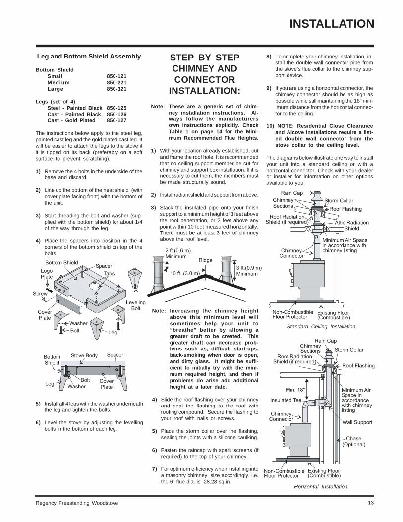
8) To complete your chimney installation, in-stall the double wall connector pipe fromthe stove’s flue collar to the chimney sup-port device.
9) If you are using a horizontal connector, thechimney connector should be as high aspossible while still maintaining the 18" min-imum distance from the horizontal connec-tor to the ceiling.
10) NOTE: Residential Close Clearanceand Alcove installations require a list-ed double wall connector from thestove collar to the ceiling level.
The diagrams below illustrate one way to installyour unit into a standard ceiling or with ahorizontal connector. Check with your dealeror installer for information on other optionsavailable to you.
5) Install all 4 legs with the washer underneaththe leg and tighten the bolts.
6) Level the stove by adjusting the levellingbolts in the bottom of each leg.
Leg and Bottom Shield Assembly
Bottom ShieldSmall 850-121Medium 850-221Large 850-321
Legs (set of 4)Steel - Painted Black 850-125Cast - Painted Black 850-126Cast - Gold Plated 850-127
The instructions below apply to the steel leg,painted cast leg and the gold plated cast leg. Itwill be easier to attach the legs to the stove ifit is tipped on its back (preferably on a softsurface to prevent scratching).
1) Remove the 4 bolts in the underside of thebase and discard.
2) Line up the bottom of the heat shield (withcover plate facing front) with the bottom ofthe unit.
3) Start threading the bolt and washer (sup-plied with the bottom shield) for about 1/4of the way through the leg.
4) Place the spacers into position in the 4corners of the bottom shield on top of thebolts.
INSTALLATION
STEP BY STEPCHIMNEY ANDCONNECTOR
INSTALLATION:
Note: These are a generic set of chim-ney installation instructions. Al-ways follow the manufacturersown instructions explicitly. CheckTable 1 on page 14 for the Mini-mum Recommended Flue Heights.
1) With your location already established, cutand frame the roof hole. It is recommendedthat no ceiling support member be cut forchimney and support box installation. If it isnecessary to cut them, the members mustbe made structurally sound.
2) Install radiant shield and support from above.
3) Stack the insulated pipe onto your finishsupport to a minimum height of 3 feet abovethe roof penetration, or 2 feet above anypoint within 10 feet measured horizontally.There must be at least 3 feet of chimneyabove the roof level.
Note: Increasing the chimney heightabove this minimum level willsometimes help your unit to“breathe” better by allowing agreater draft to be created. Thisgreater draft can decrease prob-lems such as, difficult start-ups,back-smoking when door is open,and dirty glass. It might be suffi-cient to initially try with the mini-mum required height, and then ifproblems do arise add additionalheight at a later date.
4) Slide the roof flashing over your chimneyand seal the flashing to the roof withroofing compound. Secure the flashing toyour roof with nails or screws.
5) Place the storm collar over the flashing,sealing the joints with a silicone caulking.
6) Fasten the raincap with spark screens (ifrequired) to the top of your chimney.
7) For optimum efficiency when installing intoa masonry chimney, size accordingly, i.e.the 6" flue dia. is 28.28 sq.in.
Regency Freestanding Woodstove14
INSTALLATION
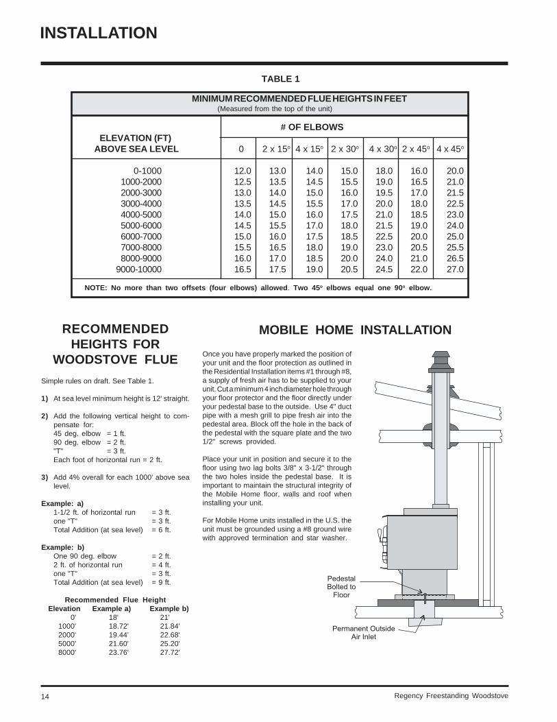
TABLE 1
MINIMUM RECOMMENDED FLUE HEIGHTS IN FEET(Measured from the top of the unit)
# OF ELBOWS ELEVATION (FT) ABOVE SEA LEVEL 0 2 x 15o 4 x 15o 2 x 30o 4 x 30o 2 x 45o 4 x 45o
0-1000 12.0 13.0 14.0 15.0 18.0 16.0 20.01000-2000 12.5 13.5 14.5 15.5 19.0 16.5 21.02000-3000 13.0 14.0 15.0 16.0 19.5 17.0 21.53000-4000 13.5 14.5 15.5 17.0 20.0 18.0 22.54000-5000 14.0 15.0 16.0 17.5 21.0 18.5 23.05000-6000 14.5 15.5 17.0 18.0 21.5 19.0 24.06000-7000 15.0 16.0 17.5 18.5 22.5 20.0 25.07000-8000 15.5 16.5 18.0 19.0 23.0 20.5 25.58000-9000 16.0 17.0 18.5 20.0 24.0 21.0 26.5
9000-10000 16.5 17.5 19.0 20.5 24.5 22.0 27.0
NOTE: No more than two offsets (four elbows) allowed. Two 45o elbows equal one 90o elbow.
MOBILE HOME INSTALLATIONRECOMMENDEDHEIGHTS FOR
WOODSTOVE FLUE
Simple rules on draft. See Table 1.
1) At sea level minimum height is 12' straight.
2) Add the following vertical height to com-pensate for:45 deg. elbow = 1 ft.90 deg. elbow = 2 ft."T" = 3 ft.Each foot of horizontal run = 2 ft.
3) Add 4% overall for each 1000' above sealevel.
Example: a)1-1/2 ft. of horizontal run = 3 ft.one "T" = 3 ft.Total Addition (at sea level) = 6 ft.
Example: b)One 90 deg. elbow = 2 ft.2 ft. of horizontal run = 4 ft.one "T" = 3 ft.Total Addition (at sea level) = 9 ft.
Recommended Flue Height Elevation Example a) Example b)
0' 18' 21'1000' 18.72' 21.84'2000' 19.44' 22.68'5000' 21.60' 25.20'8000' 23.76' 27.72'
Once you have properly marked the position ofyour unit and the floor protection as outlined inthe Residential Installation items #1 through #8,a supply of fresh air has to be supplied to yourunit. Cut a minimum 4 inch diameter hole throughyour floor protector and the floor directly underyour pedestal base to the outside. Use 4" ductpipe with a mesh grill to pipe fresh air into thepedestal area. Block off the hole in the back ofthe pedestal with the square plate and the two1/2" screws provided.
Place your unit in position and secure it to thefloor using two lag bolts 3/8" x 3-1/2" throughthe two holes inside the pedestal base. It isimportant to maintain the structural integrity ofthe Mobile Home floor, walls and roof wheninstalling your unit.
For Mobile Home units installed in the U.S. theunit must be grounded using a #8 ground wirewith approved termination and star washer.
Regency Freestanding Woodstove 15
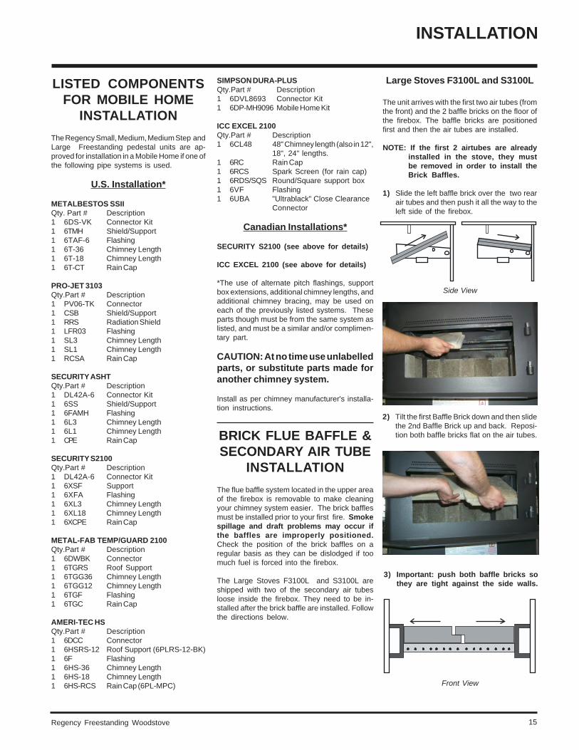
Large Stoves F3100L and S3100L
The unit arrives with the first two air tubes (fromthe front) and the 2 baffle bricks on the floor ofthe firebox. The baffle bricks are positionedfirst and then the air tubes are installed.
NOTE: If the first 2 airtubes are alreadyinstalled in the stove, they mustbe removed in order to install theBrick Baffles.
1) Slide the left baffle brick over the two rearair tubes and then push it all the way to theleft side of the firebox.
Front View
SIMPSON DURA-PLUSQty.Part # Description1 6DVL8693 Connector Kit1 6DP-MH9096 Mobile Home Kit
ICC EXCEL 2100Qty.Part # Description1 6CL48 48" Chimney length (also in 12",
18", 24" lengths.1 6RC Rain Cap1 6RCS Spark Screen (for rain cap)1 6RDS/SQS Round/Square support box1 6VF Flashing1 6UBA "Ultrablack" Close Clearance
Connector
Canadian Installations*
SECURITY S2100 (see above for details)
ICC EXCEL 2100 (see above for details)
*The use of alternate pitch flashings, supportbox extensions, additional chimney lengths, andadditional chimney bracing, may be used oneach of the previously listed systems. Theseparts though must be from the same system aslisted, and must be a similar and/or complimen-tary part.
CAUTION: At no time use unlabelledparts, or substitute parts made foranother chimney system.
Install as per chimney manufacturer's installa-tion instructions.
BRICK FLUE BAFFLE &SECONDARY AIR TUBE
INSTALLATION
The flue baffle system located in the upper areaof the firebox is removable to make cleaningyour chimney system easier. The brick bafflesmust be installed prior to your first fire. Smokespillage and draft problems may occur ifthe baffles are improperly positioned.Check the position of the brick baffles on aregular basis as they can be dislodged if toomuch fuel is forced into the firebox.
The Large Stoves F3100L and S3100L areshipped with two of the secondary air tubesloose inside the firebox. They need to be in-stalled after the brick baffle are installed. Followthe directions below.
LISTED COMPONENTSFOR MOBILE HOME
INSTALLATION
The Regency Small, Medium, Medium Step andLarge Freestanding pedestal units are ap-proved for installation in a Mobile Home if one ofthe following pipe systems is used.
U.S. Installation*
METALBESTOS SSIIQty. Part # Description1 6DS-VK Connector Kit1 6TMH Shield/Support1 6TAF-6 Flashing1 6T-36 Chimney Length1 6T-18 Chimney Length1 6T-CT Rain Cap
PRO-JET 3103Qty.Part # Description1 PV06-TK Connector1 CSB Shield/Support1 RRS Radiation Shield1 LFR03 Flashing1 SL3 Chimney Length1 SL1 Chimney Length1 RCSA Rain Cap
SECURITY ASHTQty.Part # Description1 DL42A-6 Connector Kit1 6SS Shield/Support1 6FAMH Flashing1 6L3 Chimney Length1 6L1 Chimney Length1 CPE Rain Cap
SECURITY S2100Qty.Part # Description1 DL42A-6 Connector Kit1 6XSF Support1 6XFA Flashing1 6XL3 Chimney Length1 6XL18 Chimney Length1 6XCPE Rain Cap
METAL-FAB TEMP/GUARD 2100Qty.Part # Description1 6DWBK Connector1 6TGRS Roof Support1 6TGG36 Chimney Length1 6TGG12 Chimney Length1 6TGF Flashing1 6TGC Rain Cap
AMERI-TEC HSQty.Part # Description1 6DCC Connector1 6HSRS-12 Roof Support (6PLRS-12-BK)1 6F Flashing1 6HS-36 Chimney Length1 6HS-18 Chimney Length1 6HS-RCS Rain Cap (6PL-MPC)
INSTALLATION
2) Tilt the first Baffle Brick down and then slidethe 2nd Baffle Brick up and back. Reposi-tion both baffle bricks flat on the air tubes.
3) Important: push both baffle bricks sothey are tight against the side walls.
Side View
Regency Freestanding Woodstove16
INSTALLATION
Side View
Front View
Front View
Side View
Front View
Front View
3) Tilt the left baffle brick up on top of the sidechannel and it will leave enough room toposition the right baffle brick in the samemanner as Step 1) above. Then repositionthe left baffle brick flat on the air tube.
manner as Step 1) above. Then repositionthe left baffle brick flat on the air tubes.
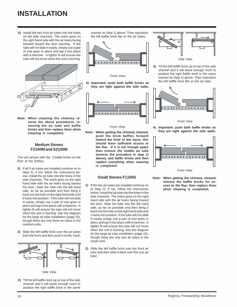
4) Install the two front air tubes into the holeson the side channels. The notch goes onthe right hand side with the air holes facingforward toward the door opening. If thetube will not slide in easily, simply use a pairof vise grips or pliers and tap it into placewith a hammer. A tighter fit will ensure thetube will not move when the unit is burning.
Note: When cleaning the chimney re-verse the above procedures, re-moving the air tube and bafflebricks and then replace them whencleaning is completed.
Medium StovesF2100M and S2100M
The unit arrives with the 2 baffle bricks on thefloor of the firebox.
1) If all 3 air tubes are installed continue on toStep 2), if not, follow the instructions be-low. Install the air tube into the holes in theside channels. The notch goes on the righthand side with the air holes facing towardthe door. Slide the tube into the left handside, as far as possible and then bring itback into the hole on the right hand side untilit locks into position. If the tube will not slidein easily, simply use a pair of vise grips orpliers and tap it into place with a hammer. Atighter fit will ensure the tube will not movewhen the unit is burning. See the diagramfor the large air tube installation (page 15),though there are only three air tubes in themedium units.
2) Slide the left baffle brick over the air tubesfrom the front and then push it to the back.
4) Important: push both baffle bricks sothey are tight against the side walls.
Note: When getting the chimney cleaned,push the brick baffles forwardtoward the front of the stove, thisshould leave sufficient access tothe flue. If it is not enough spacethen remove the middle air tube(reverse the procedure in step 1)above), and baffle bricks and thenreplace everything when cleaningis completed.
Small Stoves F1100S
1) If the two air tubes are installed continue onto Step 2), if not, follow the instructionsbelow. Install the air tube into the holes in theside channels. The notch goes on the righthand side with the air holes facing towardthe door. Slide the tube into the left handside, as far as possible and then bring itback into the hole on the right hand side untilit locks into position. If the tube will not slidein easily simply use a pair of vise grips orpliers and tap it into place with a hammer. Atighter fit will ensure the tube will not movewhen the unit is burning. See the diagramfor the large air tube installation (page 15),though there are only two air tubes in thesmall units.
2) Slide the left baffle brick over the front airtube and then slide it back over the rear airtube.
3) Tilt the left baffle brick up on top of the sidechannel and it will leave enough room toposition the right baffle brick in the same
4) Important: push both baffle bricks sothey are tight against the side walls.
Note: When getting the chimney cleaned,remove the baffle bricks for ac-cess to the flue, then replace themwhen cleaning is completed.
Regency Freestanding Woodstove 17
OPTIONALACCESSORIES
The pieces listed below can be purchased andinstalled during the initial installation or added onlater.
Freestanding - MediumF2100 & S2100
Freestanding - Large F3100
DOOR HANDLE
Attach spring handle by rotating counter clock-wise onto rod. Ensure that the rod fits into theentire length of the spring handle. See Diagrambelow.
GLASS INSTALLATION
Your Regency stove is supplied with 5 mmNeoceram ceramic glass that will withstand thehighest heat that your unit will produce. In theevent that you break your glass by impact,purchase your replacement from an authorizedRegency dealer only.
Remove the door from the stove and removethe glass retainer. Position the glass in the door,make sure that the glass gasketing will properlyseal your unit, and replace the retainer, it shouldrest on the gasket not the glass. Tighten secure-ly, but do not wrench down on the glass as thismay cause the glass to break.
INSTALLATION
See page 20 for Ash Drawer Operating in-structions.
Bottom Shield Ash Drawer Kit(850-101 )
1) Remove the bricks from the floor of thefirebox.
2) Remove and discard the cover plate byremoving the two screws on the front ofthe Bottom Shield.
3) Remove the ash dump cover plates (oneinside the firebox and one on the undersideof the firebox) by removing the two nutsand bolts holding the 2 plates together frominside the firebox.
4) Push the ash plug into the hole inside thefirebox and replace all the bricks except forthe brick over the ash plug. See the brickdiagrams on page 16.
5) Place the ash plug tool beside the lid, thenslide the ash drawer inside.
See page 20 for Ash Drawer Operating in-structions.
Freestanding - Small F1100
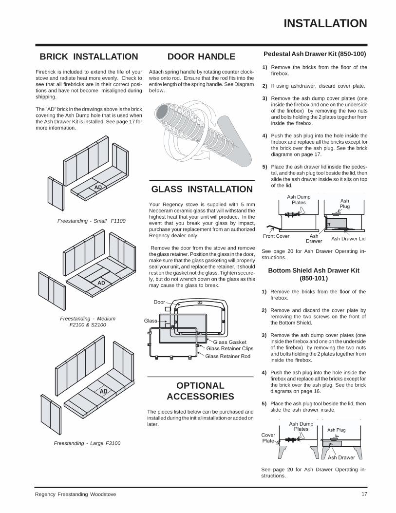
BRICK INSTALLATION
Firebrick is included to extend the life of yourstove and radiate heat more evenly. Check tosee that all firebricks are in their correct posi-tions and have not become misaligned duringshipping.
The "AD" brick in the drawings above is the brickcovering the Ash Dump hole that is used whenthe Ash Drawer Kit is installed. See page 17 formore information.
Pedestal Ash Drawer Kit (850-100)
1) Remove the bricks from the floor of thefirebox.
2) If using ashdrawer, discard cover plate.
3) Remove the ash dump cover plates (oneinside the firebox and one on the undersideof the firebox) by removing the two nutsand bolts holding the 2 plates together frominside the firebox.
4) Push the ash plug into the hole inside thefirebox and replace all the bricks except forthe brick over the ash plug. See the brickdiagrams on page 17.
5) Place the ash drawer lid inside the pedes-tal, and the ash plug tool beside the lid, thenslide the ash drawer inside so it sits on topof the lid.
Regency Freestanding Woodstove18
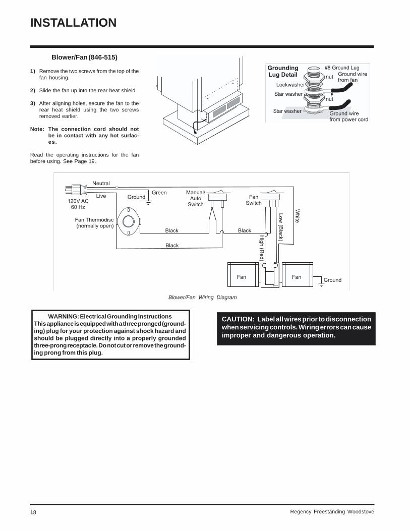
Blower/Fan (846-515)
1) Remove the two screws from the top of thefan housing.
2) Slide the fan up into the rear heat shield.
3) After aligning holes, secure the fan to therear heat shield using the two screwsremoved earlier.
Note: The connection cord should notbe in contact with any hot surfac-es.
Read the operating instructions for the fanbefore using. See Page 19.
INSTALLATION
Blower/Fan Wiring Diagram
CAUTION: Label all wires prior to disconnectionwhen servicing controls. Wiring errors can causeimproper and dangerous operation.
WARNING: Electrical Grounding InstructionsThis appliance is equipped with a three pronged (ground-ing) plug for your protection against shock hazard andshould be plugged directly into a properly groundedthree-prong receptacle. Do not cut or remove the ground-ing prong from this plug.
Regency Freestanding Woodstove 19
OPERATING INSTRUCTIONS
4) After about 15 to 20 minutes, when yourwood has begun to burn strongly, adjustyour draft control down to keep the fire ata moderate level.
WARNING: Never build a roaring fire ina cold stove. Always warm yourstove up slowly!
5) Once a bed of coals has been established,you may adjust the draft control to a lowsetting to operate the unit at its most effi-cient mode.
6) During the first few fires, keep the com-bustion rate at a moderate level and avoida large fire. Only after 5 or 6 such fires canyou operate the stove at its maximumsetting, and only after the metal has beenwarmed.
7) For the first few days, the stove will giveoff an odour from the paint. This is to beexpected as the high temperature paintbecomes seasoned. Windows and/ordoors should be left open to provide ade-quate ventilation while this temporary con-dition exists. Burning the stove at a veryhigh temperature the first few times maydamage the paint. Burn fires at a moderatelevel the first few days.
8) Do not place anything on the stove topduring the curing process. This may resultin damage to your paint finish.
9) During the first few days it may be moredifficult to start the fire. As you dry out yourfirebrick and your masonry flue, your draftwill increase.
10) For those units installed at higher eleva-tions or into sub-standard masonry fire-places, drafting problems may occur. Con-sult an experienced dealer or mason onmethods of increasing your draft.
11) Some cracking and popping noises may beexperienced during the heating up proc-ess. These noises will be minimal whenyour unit reaches temperature.
12) Before opening your door to reload, opendraft fully for approximately 10 to 15 sec-onds until fire has been re-established.This will minimize any smoking.
13) All fuel burning appliances consume oxy-gen during operation. It is important thatyou supply a source of fresh air to your unitwhile burning. A slightly opened windowis sufficient for the purpose. If you alsohave a fireplace in your home, a downdraftmay be created by your Regency Stovecausing a draft down your chimney. If thisoccurs, slightly open a window near yourunit.
OPERATINGINSTRUCTIONS
With your unit now correctly installed andsafety inspected by your local authority, youare now ready to start a fire. Before establish-ing your first fire, it is important that you fullyunderstand the operation of your draft control.
DRAFT CONTROL
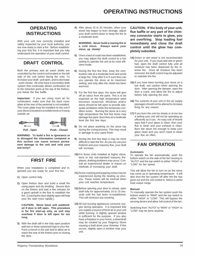
Both the primary and air wash drafts arecontrolled by the control rod located on the leftside of the unit (when facing the unit). Toincrease your draft - pull open, and to decrease- push closed. All units have a secondary draftsystem that continually allows combustion airto the induction ports at the top of the firebox,just below the flue baffle.
Important: If you are using room air forcombustion, make sure that the back coverplate at the rear of the pedestal is not installed.The cover plate must be installed on the unit ifyour stove is located in a mobile home or if usingoutside air.
Pull - Open Push - Closed
WARNING: To build a fire in ignorance orto disregard the information contained inthis section can cause serious perma-nent damage to the unit and void yourwarranty!!
FIRST FIRE
When your installation is completed and in-spected you are ready for your first fire.
1) Open control fully.
2) Open firebox door and build a small fireusing paper and dry kindling. Secure dooron the firebox and wait a few minutes fora good updraft in the flue to establish thefire. (Leaving the door slightly open will helpyour fire start more rapidly.)
CAUTION: Never leave unit unattend-ed if door is left open. This procedureis for fire start-up only, as unit mayoverheat if door is left open for toolong.
3) With the draft still in the fully open positionadd two or three seasoned logs to your fire.Form a trench in the ash bed to allow air toreach the rear of the firebox prior to closingthe door.
CAUTION: If the body of your unit,flue baffle or any part of the chim-ney connector starts to glow, youare overfiring. Stop loading fuelimmediately and close the draftcontrol until the glow has com-pletely subsided.
14) Green or wet wood is not recommendedfor your unit. If you must add wet or greenfuel, open the draft control fully until allmoisture has been dispersed by the in-tense fire. Once all moisture has beenremoved, the draft control may be adjustedto maintain the fire.
15) If you have been burning your stove on alow draft, use caution when opening thedoor. After opening the damper, open thedoor a crack, and allow the fire to adjustbefore fully opening the door.
16) The controls of your unit or the air supplypassages should not be altered to increasefiring for any reason.
17) If you burn the unit too slowly or at too lowa setting your unit will not be operating asefficiently as it can. An easy rule of thumbsays that if your glass is clean, then yourflue is clean and your exhaust is clean.Burn the stove hot enough to keep yourglass clean and you won't need to cleanyour flue as often.
FAN OPERATION
AutomaticTo operate the fan automatically, push thebottom switch on the side of the fan housing to"AUTO" and the top switch to either "HIGH" or"LOW" for fan speed.
This will allow the fan to turn on as the stovehas come up to operating temperature. It willalso shut the fan system off after the fire hasgone out and the unit cooled to below a usefulheat output range.
ManualTo manually operate the fan system push thebottom switch to "MAN" and the top switch toeither "HIGH" or "LOW". This will bypass thesensing device and allow full control of the fan.
Switching from "AUTO" to "MAN" or "HIGH" to"LOW" may be done anytime.
Regency Freestanding Woodstove20
ASH DISPOSAL
During constant use, ashes should be removedevery few days. The Ash Drawer option fea-tures a convenient ash dump for easy removalof ash, see "Modular Options" on page 9.
Safety Precautions
1) Do not allow ashes to build up to the loadingdoors! Only remove ashes when the firehas died down. Even then, expect to finda few hot embers.
2) Please take care to prevent the build-up ofash around the start-up air housing locatedinside the stove box, under the loading doorlip.
3) Never start a fire if the ash plug and ashdrawer are not in place. This will causeoverfiring which can cause excessivewarping of the stove. Evidence of overfir-ing can void the warranty on your stove.
4) The firebricks are brittle and can be dam-aged if the plug is replaced carelessly orpieces that are too large are forced throughthe hole.
Ash Drawer Operating Guideline
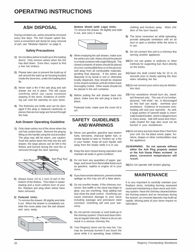
1) Only clean ashes out of the stove when theunit has cooled down. Remove the plug bylifting on the handle using the tool provided.The plug may still be warm, use caution.Push the ashes down the hole into the ashdrawer, the large pieces can be left in thefirebox and burned during the next fire orremoved through the door opening.
OPERATING INSTRUCTIONS
2) Always leave 1/2 to 1 inch of ash in thebottom of the firebox. This helps in easierstarting and a more uniform burn of yourfire. Replace ash plug when ashes havebeen removed.
3) Pedestal Units:To remove the drawer, lift slightly and slideit out. When the drawer is completely out,slide the cover plate over the ash drawerand carry away.
Bottom Shield (with Legs) Units:To remove the drawer, lift slightly and slideit out, and carry it away.
4) When emptying the ash drawer, make surethe ashes are cold. Ashes should be placedin a metal container with a tight fitting lid. Theclosed container of ashes should be placedon a non-combustible floor or on the ground,well away from all combustible materials,pending final disposal. If the ashes aredisposed of by burial in soil or otherwiselocally dispersed, they should be retainedin the closed container until all cinders havethoroughly cooled. Other waste should notbe placed in the ash container.
5) Before putting the ash drawer back intoplace, make sure the ash plug is back inplace.
Pedestal Units: make sure the cover lid isoff.
SAFETY GUIDELINESAND WARNINGS
1) Never use gasoline, gasoline type lanternfuels, kerosene, charcoal lighter fuel, orsimilar liquids to start or ‘freshen up’ a firein your heater. Keep all such liquids wellaway from the heater while it is in use.
2) Keep the door closed during operation andmaintain all seals in good condition.
3) Do not burn any quantities of paper, gar-bage, and never burn flammable fluids suchas gasoline, naptha or engine oil in yourstove.
4) If you have smoke detectors, prevent smokespillage as this may set off a false alarm.
5) Do not overfire heater. If the chimney con-nector, flue baffle or the stove top begin toglow, you are overfiring. Stop adding fueland close the draft control. Overfiring cancause extensive damage to your stoveincluding warpage and premature steelcorrosion. Overfiring will void your war-ranty.
6) Do not permit creosote or soot build-up inthe chimney system. Check and clean chim-ney at regular intervals. Failure to do so canresult in a serious chimney fire.
7) Your Regency stove can be very hot. Youmay be seriously burned if you touch thestove while it is operating, keep children,
clothing and furniture away. Warn chil-dren of the burn hazard.
8) The stove consumes air while operating,provide adequate ventilation with an airduct or open a window while the stove isin use.
9) Do not connect this unit to a chimney flueserving another appliance.
10) Do not use grates or andirons or othermethods for supporting fuel. Burn directlyon the bricks.
11) Open the draft control fully for 10 to 15seconds prior to slowly opening the doorwhen refuelling the fire.
12) Do not connect your unit to any air distribu-tion duct.
13) Your woodstove should burn dry, stand-ard firewood only. The use of cut lumber,plywood, “mill ends”, etc. is discouragedas this fuel can easily overheat yourwoodstove. Evidence of excessive over-heating will void your warranty. As well,a large portion of sawmill waste is chem-ically treated lumber, which is illegal to burnin many areas. Salt drift wood and chem-ically treated fire logs also must not beburned in your woodstoves.
14) Do not store any fuel closer than 2 feet fromyour unit. Do not place wood, paper, fur-niture, drapes or other combustibles nearthe appliance.
15) WARNING: Do not operate withouteither the Ash Plug properly seatedor the Ash Dump Plates screwed inplace, excessive temperatures willresult.
16) Do not operate with broken glazing.
MAINTENANCE
It is very important to carefully maintain yourfireplace stove, including burning seasonedwood and maintaining a clean stove and chim-ney system. Have the chimney cleaned beforethe burning season and as necessary duringthe season, as creosote deposits may build uprapidly. Moving parts of your stove require nolubrication.
Regency Freestanding Woodstove 21
MAINTENANCE
CREOSOTE
When wood is burned slowly, it produces tarand other organic vapours, which when com-bined with moisture, form creosote. The creo-sote vapours condense in the relatively coolchimney flue of a slow burning fire. As a result,creosote residue accumulates on the flue lin-ing. When ignited, this creosote can result in anextremely hot fire.
WARNING: Things to remember in case of achimney fire:
1. Close all draft and damper controls.
2. CALL THE FIRE DEPARTMENT.
Ways to Prevent and Keep UnitFree of Creosote
1) Burn stove with the draft control wide openfor about 10-15 minutes every morningduring burning season.
2) Burn stove with draft control wide open forabout 10 - 15 minutes every time you applyfresh wood. This allows the wood toachieve the charcoal stage faster and burnsup any unburned gas vapours which mightotherwise be deposited within the system.
3) Only burn seasoned wood! Avoid burn-ing wet or green wood. Seasoned woodhas been dried at least one year.
4) A small hot fire is preferable to a largesmouldering one that can deposit creosotewithin the system.
5) Check the chimney at least twice a monthduring the burning season for creosotebuild-up.
6) Have chimney system and unit cleaned bycompetent chimney sweeps twice a yearduring the first year of use and at least oncea year thereafter or when a significantlayer of creosote has accumulated (3 mm/1/8" or more) it should be removed to reducethe risk of a chimney fire.
MAINTENANCE OFGOLD-PLATED DOORS
The gold electroplated finish on the door re-quires little maintenance, and need only becleaned with a damp cloth. DO NOT use abra-sive materials or chemical cleaners, as theymay harm the finish and void the warranty.
LATCH ADJUSTMENT
The door latch may require adjustment as thedoor gasket material compresses after a fewfires. Removal of the spacer washer, shownin the diagram below, will allow the latch to bemoved closer to the door frame, causing atighter seal. Remove and replace the nuts,washer and spacer as shown.
DOOR GASKET
If the door gasket requires replacement 7/8" diam-eter material must be used. Regency uses AMA-TEX # 10-863KR 7/8" dia. gasket. A proper hightemperature gasket adhesive is required. See yourRegency Dealer.
GLASS MAINTENANCE
Your Regency stove is supplied with 5 mmNeoceram ceramic glass that will withstandthe highest heat that your unit will produce. Inthe event that you break your glass by impact,purchase your replacement from an author-ized Regency dealer only, and follow our step-by-step instructions for replacement.
Allow the stove to cool down before cleaningthe glass, do not clean the glass when it is hot.Do not use abrasive cleaners.
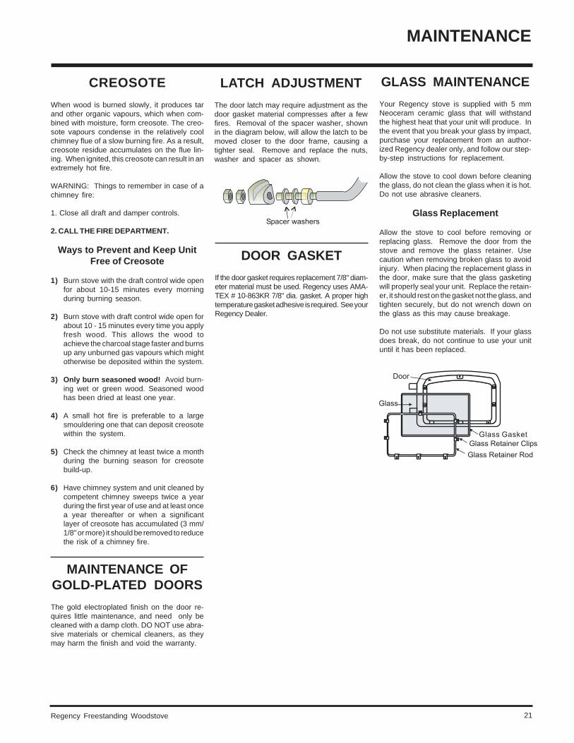
Glass Replacement
Allow the stove to cool before removing orreplacing glass. Remove the door from thestove and remove the glass retainer. Usecaution when removing broken glass to avoidinjury. When placing the replacement glass inthe door, make sure that the glass gasketingwill properly seal your unit. Replace the retain-er, it should rest on the gasket not the glass, andtighten securely, but do not wrench down onthe glass as this may cause breakage.
Do not use substitute materials. If your glassdoes break, do not continue to use your unituntil it has been replaced.
Regency Freestanding Woodstove22
PARTS LIST
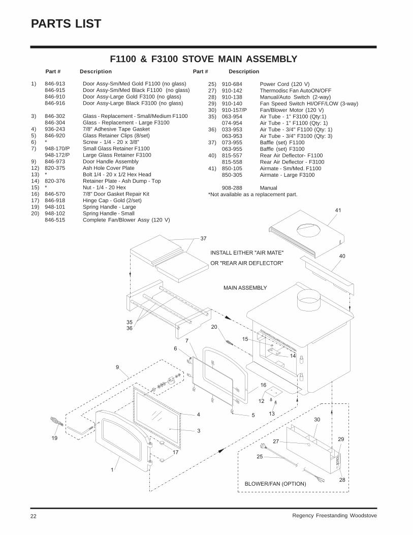
1) 846-913 Door Assy-Sm/Med Gold F1100 (no glass)846-915 Door Assy-Sm/Med Black F1100 (no glass)846-910 Door Assy-Large Gold F3100 (no glass)846-916 Door Assy-Large Black F3100 (no glass)
3) 846-302 Glass - Replacement - Small/Medium F1100846-304 Glass - Replacement - Large F3100
4) 936-243 7/8" Adhesive Tape Gasket5) 846-920 Glass Retainer Clips (8/set)6) * Screw - 1/4 - 20 x 3/8"7) 948-170/P Small Glass Retainer F1100
948-172/P Large Glass Retainer F31009) 846-973 Door Handle Assembly12) 820-375 Ash Hole Cover Plate13) * Bolt 1/4 - 20 x 1/2 Hex Head14) 820-376 Retainer Plate - Ash Dump - Top15) * Nut - 1/4 - 20 Hex16) 846-570 7/8" Door Gasket Repair Kit17) 846-918 Hinge Cap - Gold (2/set)19) 948-101 Spring Handle - Large20) 948-102 Spring Handle - Small
846-515 Complete Fan/Blower Assy (120 V)
F1100 & F3100 STOVE MAIN ASSEMBLY Part # Description Part # Description
25) 910-684 Power Cord (120 V)27) 910-142 Thermodisc Fan AutoON/OFF28) 910-138 Manual/Auto Switch (2-way)29) 910-140 Fan Speed Switch HI/OFF/LOW (3-way)30) 910-157/P Fan/Blower Motor (120 V)35) 063-954 Air Tube - 1" F3100 (Qty:1)
074-954 Air Tube - 1" F1100 (Qty: 1)36) 033-953 Air Tube - 3/4" F1100 (Qty: 1)
063-953 Air Tube - 3/4" F3100 (Qty: 3)37) 073-955 Baffle (set) F1100
063-955 Baffle (set) F310040) 815-557 Rear Air Deflector- F1100
815-558 Rear Air Deflector - F310041) 850-105 Airmate - Sm/Med. F1100
850-305 Airmate - Large F3100
908-288 Manual*Not available as a replacement part.
Regency Freestanding Woodstove 23
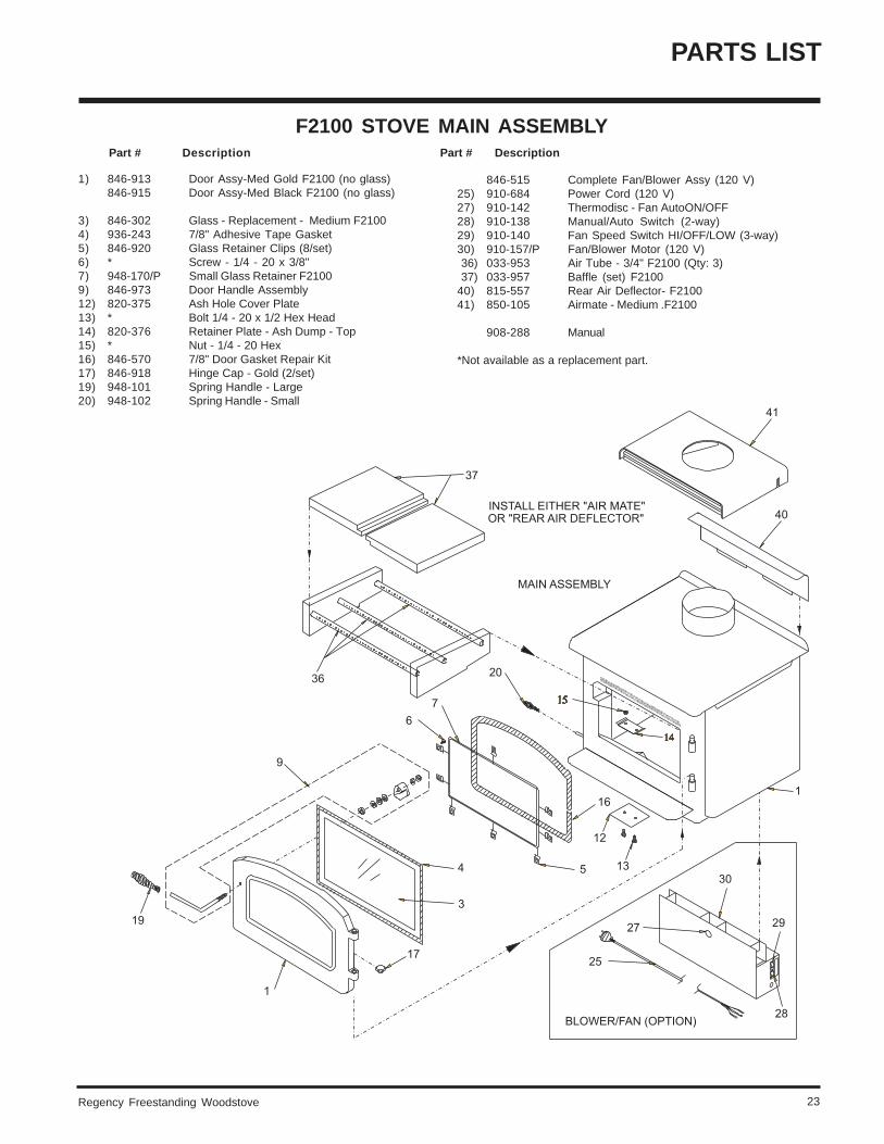
1) 846-913 Door Assy-Med Gold F2100 (no glass)846-915 Door Assy-Med Black F2100 (no glass)
3) 846-302 Glass - Replacement - Medium F21004) 936-243 7/8" Adhesive Tape Gasket5) 846-920 Glass Retainer Clips (8/set)6) * Screw - 1/4 - 20 x 3/8"7) 948-170/P Small Glass Retainer F21009) 846-973 Door Handle Assembly12) 820-375 Ash Hole Cover Plate13) * Bolt 1/4 - 20 x 1/2 Hex Head14) 820-376 Retainer Plate - Ash Dump - Top15) * Nut - 1/4 - 20 Hex16) 846-570 7/8" Door Gasket Repair Kit17) 846-918 Hinge Cap - Gold (2/set)19) 948-101 Spring Handle - Large20) 948-102 Spring Handle - Small
F2100 STOVE MAIN ASSEMBLY Part # Description Part # Description
846-515 Complete Fan/Blower Assy (120 V)25) 910-684 Power Cord (120 V)27) 910-142 Thermodisc - Fan AutoON/OFF28) 910-138 Manual/Auto Switch (2-way)29) 910-140 Fan Speed Switch HI/OFF/LOW (3-way)30) 910-157/P Fan/Blower Motor (120 V) 36) 033-953 Air Tube - 3/4" F2100 (Qty: 3) 37) 033-957 Baffle (set) F210040) 815-557 Rear Air Deflector- F210041) 850-105 Airmate - Medium .F2100
908-288 Manual
*Not available as a replacement part.
PARTS LIST
Regency Freestanding Woodstove24
PARTS LIST
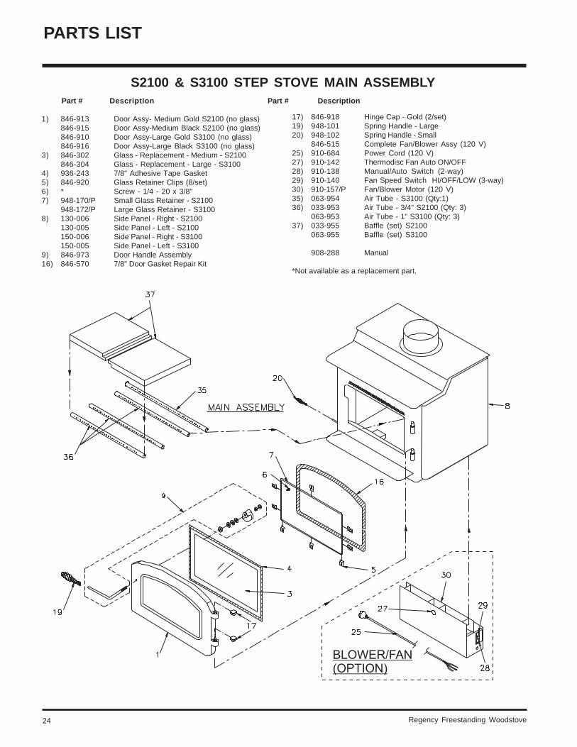
1) 846-913 Door Assy- Medium Gold S2100 (no glass)846-915 Door Assy-Medium Black S2100 (no glass)846-910 Door Assy-Large Gold S3100 (no glass)846-916 Door Assy-Large Black S3100 (no glass)
3) 846-302 Glass - Replacement - Medium - S2100846-304 Glass - Replacement - Large - S3100
4) 936-243 7/8" Adhesive Tape Gasket5) 846-920 Glass Retainer Clips (8/set)6) * Screw - 1/4 - 20 x 3/8"7) 948-170/P Small Glass Retainer - S2100
948-172/P Large Glass Retainer - S31008) 130-006 Side Panel - Right - S2100
130-005 Side Panel - Left - S2100150-006 Side Panel - Right - S3100150-005 Side Panel - Left - S3100
9) 846-973 Door Handle Assembly16) 846-570 7/8" Door Gasket Repair Kit
Part # Description Part # Description
17) 846-918 Hinge Cap - Gold (2/set)19) 948-101 Spring Handle - Large20) 948-102 Spring Handle - Small
846-515 Complete Fan/Blower Assy (120 V)25) 910-684 Power Cord (120 V)27) 910-142 Thermodisc Fan Auto ON/OFF28) 910-138 Manual/Auto Switch (2-way)29) 910-140 Fan Speed Switch HI/OFF/LOW (3-way)30) 910-157/P Fan/Blower Motor (120 V)35) 063-954 Air Tube - S3100 (Qty:1)36) 033-953 Air Tube - 3/4" S2100 (Qty: 3)
063-953 Air Tube - 1" S3100 (Qty: 3)37) 033-955 Baffle (set) S2100
063-955 Baffle (set) S3100
908-288 Manual
*Not available as a replacement part.
S2100 & S3100 STEP STOVE MAIN ASSEMBLY
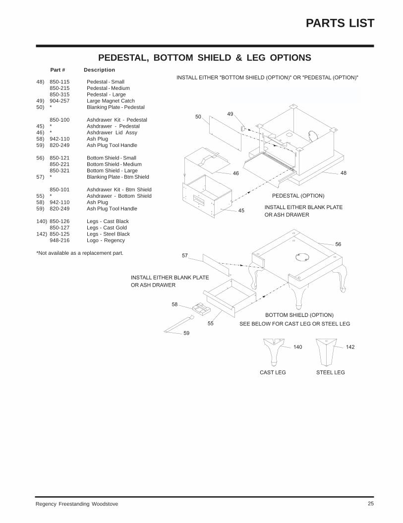
Regency Freestanding Woodstove 25
48) 850-115 Pedestal - Small850-215 Pedestal - Medium850-315 Pedestal - Large
49) 904-257 Large Magnet Catch50) * Blanking Plate - Pedestal
850-100 Ashdrawer Kit - Pedestal45) * Ashdrawer - Pedestal46) * Ashdrawer Lid Assy58) 942-110 Ash Plug59) 820-249 Ash Plug Tool Handle
56) 850-121 Bottom Shield - Small850-221 Bottom Shield - Medium850-321 Bottom Shield - Large
57) * Blanking Plate - Btm Shield
850-101 Ashdrawer Kit - Btm Shield55) * Ashdrawer - Bottom Shield58) 942-110 Ash Plug59) 820-249 Ash Plug Tool Handle
140) 850-126 Legs - Cast Black850-127 Legs - Cast Gold
142) 850-125 Legs - Steel Black948-216 Logo - Regency
*Not available as a replacement part.
PEDESTAL, BOTTOM SHIELD & LEG OPTIONS Part # Description
PARTS LIST
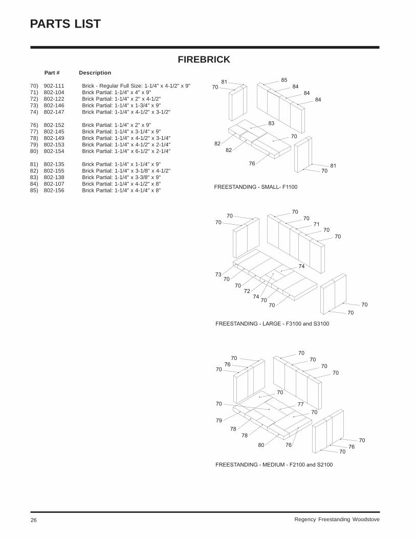
Regency Freestanding Woodstove26
70) 902-111 Brick - Regular Full Size: 1-1/4" x 4-1/2" x 9"71) 802-104 Brick Partial: 1-1/4" x 4" x 9"72) 802-122 Brick Partial: 1-1/4" x 2" x 4-1/2"73) 802-146 Brick Partial: 1-1/4" x 1-3/4" x 9"74) 802-147 Brick Partial: 1-1/4" x 4-1/2" x 3-1/2"
76) 802-152 Brick Partial: 1-1/4" x 2" x 9"77) 802-145 Brick Partial: 1-1/4" x 3-1/4" x 9"78) 802-149 Brick Partial: 1-1/4" x 4-1/2" x 3-1/4"79) 802-153 Brick Partial: 1-1/4" x 4-1/2" x 2-1/4"80) 802-154 Brick Partial: 1-1/4" x 6-1/2" x 2-1/4"
81) 802-135 Brick Partial: 1-1/4" x 1-1/4" x 9"82) 802-155 Brick Partial: 1-1/4" x 3-1/8" x 4-1/2"83) 802-138 Brick Partial: 1-1/4" x 3-3/8" x 9"84) 802-107 Brick Partial: 1-1/4" x 4-1/2" x 8"85) 802-156 Brick Partial: 1-1/4" x 4-1/4" x 8"
Part # Description
FIREBRICK
PARTS LIST
Regency Freestanding Woodstove 27
WARRANTY
Regency Fireplace Products are designed with reliability and simplicity in mind. In addition, our internal Quality AssuranceTeam carefully inspects each unit thoroughly before it leaves our door. Regency Industries Ltd. is pleased to extend this limitedlifetime warranty to the original purchaser of a Regency Product.
The Warranty: LifetimeCovered under the agreement are the following components:
Firebox, ceramic baffle, convector airmate, castings, ashdrawer, glass (thermal breakage) and all gold plating (against defectivemanufacture).
The above will be covered for parts and labour for the first five years and parts only thereafter.
Electrical components such as blowers and switches are covered for one year from the date of purchase.
Conditions:Any part or parts of this unit which in our judgement show evidence of such defects will be repaired or replaced at Regency's option,through an accredited distributor or agent provided that the defective part be returned to the distributor or agent TransportationPrepaid, if requested.
Exclusions:This limited Lifetime Warranty does not extend to include paint, door or glass gasketing, firebrick or trim. It does not cover installationand operational related problems such as over-firing, use of corrosive driftwood, downdrafts or spillage caused by environmentalconditions, nearby trees, buildings, hilltops, mountains, inadequate venting or ventilation, excessive offsets, negative air pressurescaused by mechanical systems such as furnaces, fans, clothes dryers etc.
It is essential that all submitted claims provide all of the necessary information including purchase date, serial #, type of unit andpart or parts requested.
Installer: Please complete the following information
Dealer Name & Address:______________________________________________
__________________________________________________________________
Installer: ___________________________________________________________
Phone #: ___________________________________________________________
Date Installed: ______________________________________________________
Serial No.: _________________________________________________________
Printed in Canada
Regency fireplace products are designedwith reliability and simplicity in mind. In
addition, our internal Quality AssuranceTeam carefully inspects each unit thor-
oughly before it leaves our door.
Fireplace Products InternationalLtd. is pleased to extend this Limited
Lifetime Warranty to the original pur-chaser of a Regency Product.
See the inside back cover for details.
© FPI Fireplace Products International Ltd. 2003
Regency and Classic are trademarks of FPI Fireplace Products International Ltd.
Register your Regency online athttp://www.regency-fire.com


![Untitled-1 [] · 2. VlH4)OPMaTVIBHOCTb — caüT — 3T0 B nepBSÆ0 oqepeas 1-1H4)opraaquq. MSI HaraepeHb1 MaKcmaanbHO YA06HO npeacTaBhTb 06beMbl noe3A0K, nyTeB0K, qeH](https://img.pdfslide.us/doc/110x75/5fcc309b6a40eb7d1024f2be/untitled-1-2-vlh4opmatvibhoctb-a-cat-a-3t0-b-nepbs0-oqepeas-1-1h4opraaquq.jpg)