Embed Size (px)
Citation preview
AN2623/D12/2003
LIN Temperature Sensor Using the MC68HC908QT/QY MCU
Application Note
F
ree
sca
le S
em
ico
nd
uc
tor,
I
Freescale Semiconductor, Inc.n
c..
.
By Jiri KuhnMotorola Czech System LaboratoriesRoznov p.R., Czech RepublicIntroductionMany applications in the automobile industry and other areas require connecting and transferring information between two or more nodes. As the complexity of circuits continues to increase, the amount of copper needed to connect various equipment increases, too.
One solution to this demand is to use a serial multiplex bus, such as CAN or LIN. The controller area network (CAN) bus has a higher bandwidth and is often used to transfer data to and from the engine and other major parts of the car. The local interconnect network (LIN) bus is a low-cost solution that is suited to connect smaller parts within the car. Another LIN bus advantage is that it uses only three wires: the LIN serial data line and the positive and negative supplies. Also, there is a simple way to upgrade the system or add new features because LIN is a digital solution.
This application note presents a simple LIN temperature sensor using the MC68HC908QY4 LIN evaluation board. AN2264/D: LIN Node Temperature Display deals with a temperature display implementation, but it does not cover the use of a temperature sensor. This application can be used, for example, as part of HVAC (heating, ventilation, and air conditioning), which usually includes a keypad module, flaps control, multi-purpose display, and temperature sensors.
HVAC applications are not the only applications that request temperature measurements. For example, to assign the optimal operating point, minimize exhalation, and maximize engine performance in motor control management, the temperature of the outside air must be determined.
NOTE: With the exception of mask set errata documents, if any other Motorola document contains information that conflicts with the information in the device data sheet, the data sheet should be considered to have the most current and correct data.
CodeWarrior is a registered trademark of Freescale Semiconductor, Inc.This product incorporates SuperFlash technology licensed from SST.
© Motorola, Inc., 2003
For More Information On This Product, Go to: www.freescale.com
AN2623/D
F
ree
sca
le S
em
ico
nd
uc
tor,
I
Freescale Semiconductor, Inc.n
c..
.
Temperature Sensor
When MCUs are used without having the analog-to-digital (A/D) converter reference-voltage bonded out, the main challenge with measuring temperature is calibrating the temperature-to-digital conversion. Many temperature sensors have 1°C or less accuracy (which is sufficient for such car applications), but the power supply voltage dependency of A/D conversion on the MCU affects the temperature-to-digital conversion. This measurement error can range ±11% from the nominal value.
A/D Conversion Power Supply Dependency
To show how the challenge of the A/D conversion power supply dependency can be resolved, a self-calibration procedure has been implemented in this application. As an example, the Maxim MAX6611 temperature sensor will be used. This sensor provides a voltage reference, which is almost independent of the power supply voltage. Because the value of this reference is known, the voltage output can be measured by the second A/D channel and calibrate the temperature value using the following equation:
where Ncor is a corrected temperature value; Nunc is an uncorrected temperature value (measured in the first A/D channel); Nref value corresponds to the voltage reference (TEMP_REFERENCE symbolic constant used in the source code, e.g., 0xD1 for MAX6611); and Nmref is the sensor voltage reference measured in the second A/D channel.
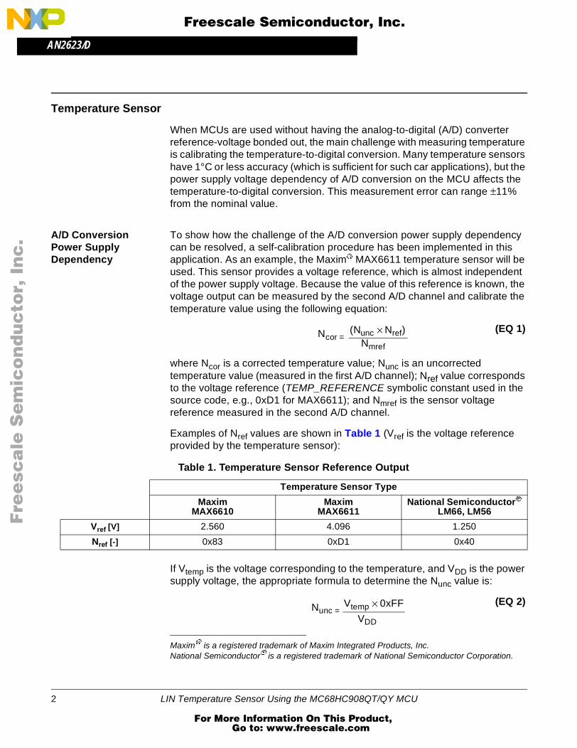
Examples of Nref values are shown in Table 1 (Vref is the voltage reference provided by the temperature sensor):
If Vtemp is the voltage corresponding to the temperature, and VDD is the power supply voltage, the appropriate formula to determine the Nunc value is:
Maxim is a registered trademark of Maxim Integrated Products, Inc.National Semiconductor is a registered trademark of National Semiconductor Corporation.
Ncor =(Nunc × Nref)
Nmref
(EQ 1)
Table 1. Temperature Sensor Reference Output
Temperature Sensor Type
Maxim MAX6610
Maxim MAX6611
National SemiconductorLM66, LM56
Vref [V] 2.560 4.096 1.250
Nref [-] 0x83 0xD1 0x40
Nunc =Vtemp × 0xFF
VDD
(EQ 2)
2 LIN Temperature Sensor Using the MC68HC908QT/QY MCU
For More Information On This Product, Go to: www.freescale.com
AN2623/DHardware
F
ree
sca
le S
em
ico
nd
uc
tor,
I
Freescale Semiconductor, Inc.n
c..
.
Temperature Sensor Limitation
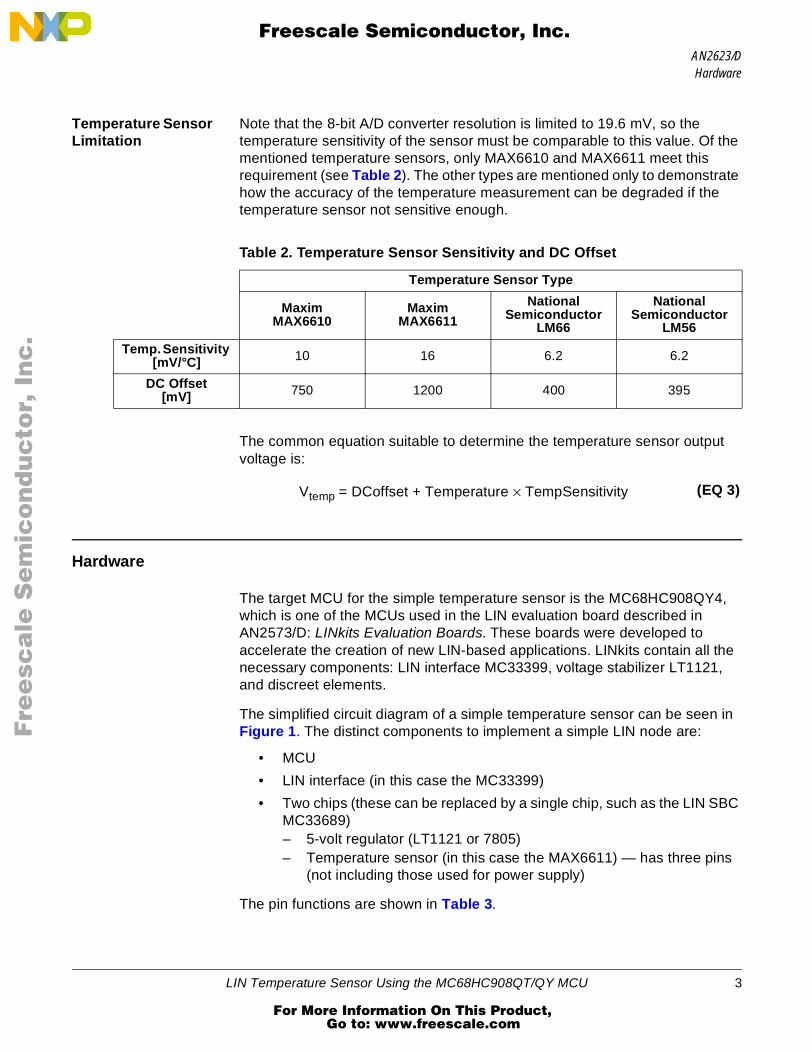
Note that the 8-bit A/D converter resolution is limited to 19.6 mV, so the temperature sensitivity of the sensor must be comparable to this value. Of the mentioned temperature sensors, only MAX6610 and MAX6611 meet this requirement (see Table 2). The other types are mentioned only to demonstrate how the accuracy of the temperature measurement can be degraded if the temperature sensor not sensitive enough.
The common equation suitable to determine the temperature sensor output voltage is:
Hardware
The target MCU for the simple temperature sensor is the MC68HC908QY4, which is one of the MCUs used in the LIN evaluation board described in AN2573/D: LINkits Evaluation Boards. These boards were developed to accelerate the creation of new LIN-based applications. LINkits contain all the necessary components: LIN interface MC33399, voltage stabilizer LT1121, and discreet elements.
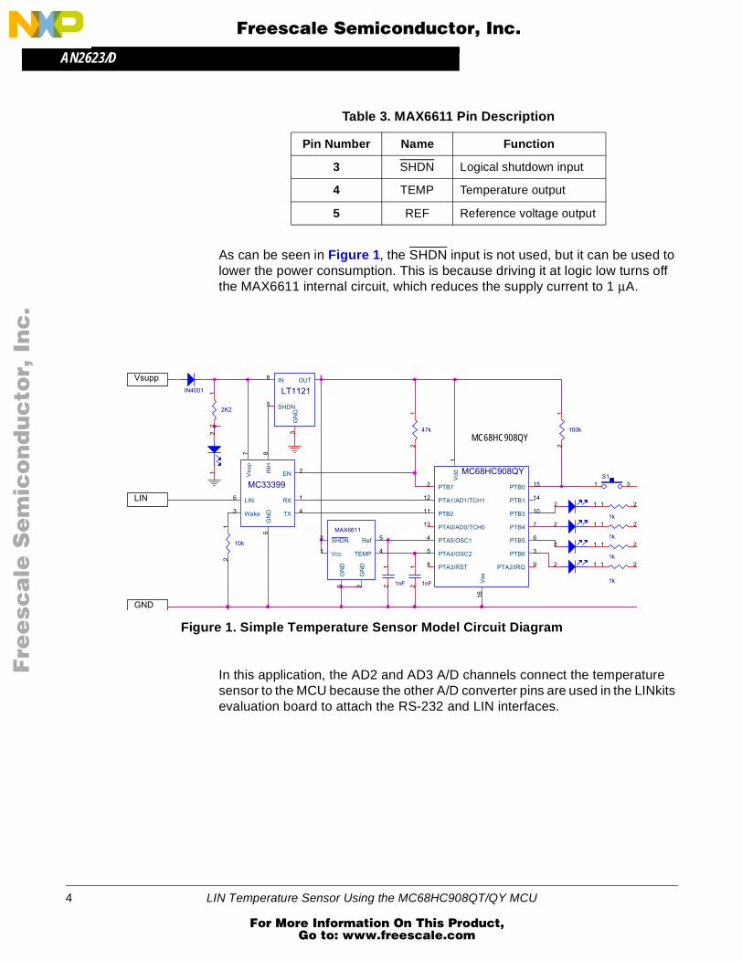
The simplified circuit diagram of a simple temperature sensor can be seen in Figure 1. The distinct components to implement a simple LIN node are:
• MCU
• LIN interface (in this case the MC33399)
• Two chips (these can be replaced by a single chip, such as the LIN SBC MC33689)– 5-volt regulator (LT1121 or 7805)– Temperature sensor (in this case the MAX6611) — has three pins
(not including those used for power supply)
The pin functions are shown in Table 3.
Table 2. Temperature Sensor Sensitivity and DC Offset
Temperature Sensor Type
Maxim MAX6610
Maxim MAX6611
National Semiconductor
LM66
National Semiconductor
LM56
Temp. Sensitivity [mV/°C] 10 16 6.2 6.2
DC Offset [mV] 750 1200 400 395
Vtemp = DCoffset + Temperature × TempSensitivity (EQ 3)
LIN Temperature Sensor Using the MC68HC908QT/QY MCU 3
For More Information On This Product, Go to: www.freescale.com
AN2623/D
F
ree
sca
le S
em
ico
nd
uc
tor,
I
Freescale Semiconductor, Inc.n
c..
.
As can be seen in Figure 1, the SHDN input is not used, but it can be used to lower the power consumption. This is because driving it at logic low turns off the MAX6611 internal circuit, which reduces the supply current to 1 µA.
Figure 1. Simple Temperature Sensor Model Circuit Diagram
In this application, the AD2 and AD3 A/D channels connect the temperature sensor to the MCU because the other A/D converter pins are used in the LINkits evaluation board to attach the RS-232 and LIN interfaces.
Table 3. MAX6611 Pin Description
Pin Number Name Function
3 SHDN Logical shutdown input
4 TEMP Temperature output
5 REF Reference voltage output
Vsupp
GND
LIN
2 1
1nF
12
1k
1 2
1k
1 22 1
MC68HC908QY
Vss
16
Vd
d1
PTB72
PTB6 3
PTA5/OSC14
PTA4/OSC25
PTB5 6
PTB4 7
PTA3/RST8 PTA2/IRQ 9
PTB3 10PTB211
PTA1/AD1/TCH112
PTA0/AD0/TCH013
PTB1 14
PTB0 15
1nF
12
LT1121
IN8 OUT 1
GN
D3
SHDN52K2
12
1k
1 2
47k
12
IN4001
S1
1 3
2 1
MAX6611
Vcc1
GN
D2
SHDN3
GN
D6
Ref 5
TEMP 4
1k
1 2
10k
12
100k
12
2 1
21
MC33399
LIN6
Wake3
Vsu
p7
EN 2
TX 4
RX 1
INH
8G
ND
5
MC68HC908QY
4 LIN Temperature Sensor Using the MC68HC908QT/QY MCU
For More Information On This Product, Go to: www.freescale.com
AN2623/DSoftware
F
ree
sca
le S
em
ico
nd
uc
tor,
I
Freescale Semiconductor, Inc.n
c..
.
Software
The temperature sensor node measures and corrects the current temperature and provides the corrected value to the other nodes. As in every LIN network, it is necessary to define a specific 6-bit long ID for each message that will be used to transfer the data between nodes. The ID is protected by two parity bits. A data field block length, which can be 1 to 8 bytes, must also be defined (according to the LIN specification, see References). In this application, 2-byte long messages are used.
LIN communication is bidirectional and driven by the master. Therefore, the slave sends the current temperature measurement value after the master sends a request for it. In the first byte, the current corrected temperature measurement is sent. The second one remains unused; therefore it can be used, for example, to transfer the reference voltage value.
The slave LED is driven according to the LSB of the first data byte received from the master. As a possible enhancement of the application, the temperature sensor type can be transferred to the slave by these messages, which allows a change in the hardware configuration without a slave software change.
Because the slave node module uses the Motorola LIN QY/QT driver, all LIN connectivity tasks are handled outside the application code. This allows developers to use the “LIN_GetMsg()” API function to receive the data provided by the master and the “LIN_PutMsg()” function to send data to the master. Using the LIN drivers allows the programmer to concentrate on the application without having to get too involved with the communications protocol. These drivers are available free of charge from http://www.motorola.com/semiconductors/LIN.
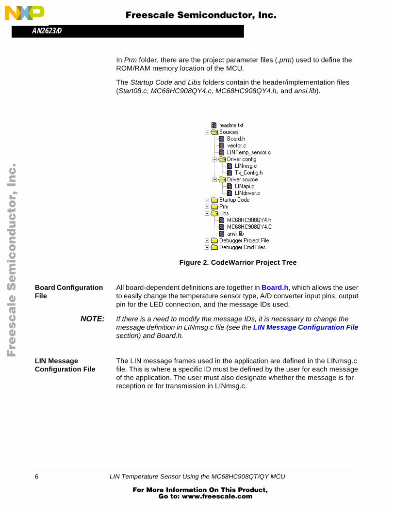
CodeWarrior Project The project is structured as shown in Figure 2. The folder Sources contains the application source code (LINtemp_sensor.c), board dependent data (Board.h), vector.c file, sub folder Driver config with LIN configuration files (LINmsg.c, TxConfig.h), and sub folder Driver source, with the Motorola LIN QT/QY drivers.
LINmsg.c and vector.c files define the behavior of the slave node. The LINmsg.c file is used to determine the LIN frames, as provided in LIN Message Configuration File section. The TxConfig.h file specifies which MCU pin is used as a LIN transmit pin. Files in Drive source sub folder contain Motorola LIN driver implementation code and, in most cases, it should not be modified by the user.
LIN Temperature Sensor Using the MC68HC908QT/QY MCU 5
For More Information On This Product, Go to: www.freescale.com
AN2623/D
F
ree
sca
le S
em
ico
nd
uc
tor,
I
Freescale Semiconductor, Inc.n
c..
.
In Prm folder, there are the project parameter files (.prm) used to define the ROM/RAM memory location of the MCU.
The Startup Code and Libs folders contain the header/implementation files (Start08.c, MC68HC908QY4.c, MC68HC908QY4.h, and ansi.lib).
Figure 2. CodeWarrior Project Tree
Board Configuration File
All board-dependent definitions are together in Board.h, which allows the user to easily change the temperature sensor type, A/D converter input pins, output pin for the LED connection, and the message IDs used.
NOTE: If there is a need to modify the message IDs, it is necessary to change the message definition in LINmsg.c file (see the LIN Message Configuration File section) and Board.h.
LIN Message Configuration File
The LIN message frames used in the application are defined in the LINmsg.c file. This is where a specific ID must be defined by the user for each message of the application. The user must also designate whether the message is for reception or for transmission in LINmsg.c.
6 LIN Temperature Sensor Using the MC68HC908QT/QY MCU
For More Information On This Product, Go to: www.freescale.com
AN2623/DSoftware
F
ree
sca
le S
em
ico
nd
uc
tor,
I
Freescale Semiconductor, Inc.n
c..
.
The message ID is written in the hexadecimal format with parity bits included, and the data field can be 2, 4, or 8 bytes long. In this application, two message IDs are used:
• Message ID equal to 0x1A (0x1A with the parity bits included) is used forreception
• Message ID 0x1B (0x5B with parity) is used for transmission
A list of all the operations necessary to set up the LINmsg.c file is presented here:
1. Create a message buffer for the frame data field of each application message.
U8 volatile Message0x1A[2]; // ID 0x1A = 0x1A with parityU8 volatile Message0x5B[2]; // ID 0x1B = 0x5B with parity
2. Define a pointer array MessagePointerTbl[] that contains pointers to all application message buffers.
U8 volatile * MessagePointerTbl[] = {Message0x1A, Message0x5B};
3. Create an identifier table (array) IdTbl[] containing all IDs relevant to this node. Note that it must be set up in the same order as in MessagePointerTbl[] and MessageCountTbl[]. And, message IDs must have parity bits included.
U8 const near IdTbl[] = {0x1A, 0x5B};
4. Then, define an array variable MessageCountTbl[]. This is a table which defines (for each available message) the length of the frame data and checksum fields. It also indicates whether the specific message should be sent or received. The least significant half-byte (LSHB) of each entry indicates the length of the data and checksum fields (length of the checksum field is equal to 1). The most significant half-byte (MSHB) is equal to 1 for message reception, and to 0 for transmission. In addition, it could also be equal to 0xF (ignore), which means that the message is ignored unless it has been updated since its last read/write.
U8 const near MessageCountTbl[] = {0x13, 0x03};
Main Program Structure
The main program flowchart can be seen in Figure 3. After the necessary MCU periphery initialization, two functions LED_display() and LIN_response() are called.
At first, the LED status is updated according the message received from the master.
The second function called from the main program loop is the LIN_response(). There the current temperature is measured (the value stored in MsgSent[0]
LIN Temperature Sensor Using the MC68HC908QT/QY MCU 7
For More Information On This Product, Go to: www.freescale.com

AN2623/D
F
ree
sca
le S
em
ico
nd
uc
tor,
I
Freescale Semiconductor, Inc.n
c..
.
variable). Then the voltage reference is measured (and stored in the MeasuredReference variable).
The next step is to determine the correction of the current measured A/D value. To do this without using a floating point value (which takes a lot of MCU CPU time), the TEMP_REFERENCE symbolic constant is multiplied by 256 and then divided by the MeasuredReference value. So, after the calculated value is used to correct the current temperature value and then divided by 256, the correct value is reached without the need to use floating point variables.
Figure 3. Main Program Flowchart
CLEAR OVERFLOW FLAG
START main()
MCU PERIPHERY
TIMEROVERFLOW?
NO
UPDATE LED STATUS
LED_display()
INITIALIZATION
INIT LIN DRIVER
LIN_Init()
LIN MESSAGE TRANSFER
LIN_response()
YES
8 LIN Temperature Sensor Using the MC68HC908QT/QY MCU
For More Information On This Product, Go to: www.freescale.com
AN2623/DSoftware
F
ree
sca
le S
em
ico
nd
uc
tor,
I
Freescale Semiconductor, Inc.n
c..
.
Project Building This section provides a brief description of how to create a new project based on the Motorola LIN QY/QT driver software. For more detailed information, it is necessary to study AN2599/D: Generic LIN Driver for MC68HC908QY4.
• Create a new project in the Metrowerks CodeWarrior development system.
• Copy the Motorola LIN QY/QT driver software into the folder structure of the project (for example, into the folders lin_src and lin_inc). The driver consists of these files: LINapi.c, LINdriver.c, LINdriver.h, LINmsg.c, and Tx_Config.h.
• Add the Motorola LIN QY/QT driver software into the CodeWarrior tool project tree (for example, into the folders Sources\Driver source and Sources\Driver config).
• In the application source file (e.g. LINtemp_sensor.c), include the LIN driver by:#include "LINdriver.h"
• Define the messages in the LINmsg.c file, as described in the LIN Message Configuration File section.
• Define the transmit pin of the LIN node in the Tx_Config.h file (default value is pin 2 of Port B).
• Update the vectors of the project in vector.c file. Specifically, it is necessary to define interrupt service routine TimA1ISR() as a VECTOR 5 (0xFFF4).
Special Considerations
Before designing an application, you should be aware of these special considerations:
• The driver uses only timer channel 1, but use of the timer modulus counter is prohibited. This is because the driver assumes that the overflow value of the timer is set to 0xFFFF. No interrupt service routine (ISR) is allowed other than the one used by the LIN driver during communication. This is because both the Tx and Rx pins are software driven and must have a predictable latency for the ISR response.
• The use of the LDA/modify/STA sequence for the control of port B in this interrupt-driven bit-banged driver is strongly discouraged because one pin of this port (PTB2) is used as a Tx pin of the LIN driver. If the level of this Tx pin is changed by an interrupt occurring during the sequence, the wrong level will be restored. The solution is to use only BSET and BCLR instructions when writing to port B.
LIN Temperature Sensor Using the MC68HC908QT/QY MCU 9
For More Information On This Product, Go to: www.freescale.com
AN2623/D
F
ree
sca
le S
em
ico
nd
uc
tor,
I
Freescale Semiconductor, Inc.n
c..
.
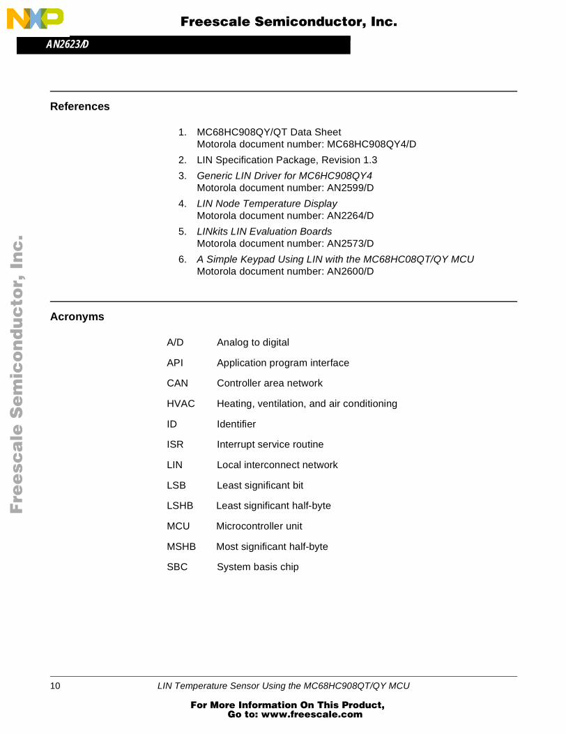
References
1. MC68HC908QY/QT Data SheetMotorola document number: MC68HC908QY4/D
2. LIN Specification Package, Revision 1.3
3. Generic LIN Driver for MC6HC908QY4Motorola document number: AN2599/D
4. LIN Node Temperature DisplayMotorola document number: AN2264/D
5. LINkits LIN Evaluation BoardsMotorola document number: AN2573/D
6. A Simple Keypad Using LIN with the MC68HC08QT/QY MCUMotorola document number: AN2600/D
Acronyms
A/D Analog to digital
API Application program interface
CAN Controller area network
HVAC Heating, ventilation, and air conditioning
ID Identifier
ISR Interrupt service routine
LIN Local interconnect network
LSB Least significant bit
LSHB Least significant half-byte
MCU Microcontroller unit
MSHB Most significant half-byte
SBC System basis chip
10 LIN Temperature Sensor Using the MC68HC908QT/QY MCU
For More Information On This Product, Go to: www.freescale.com
AN2623/DAppendix - Software Listing
F
ree
sca
le S
em
ico
nd
uc
tor,
I
Freescale Semiconductor, Inc.n
c..
.
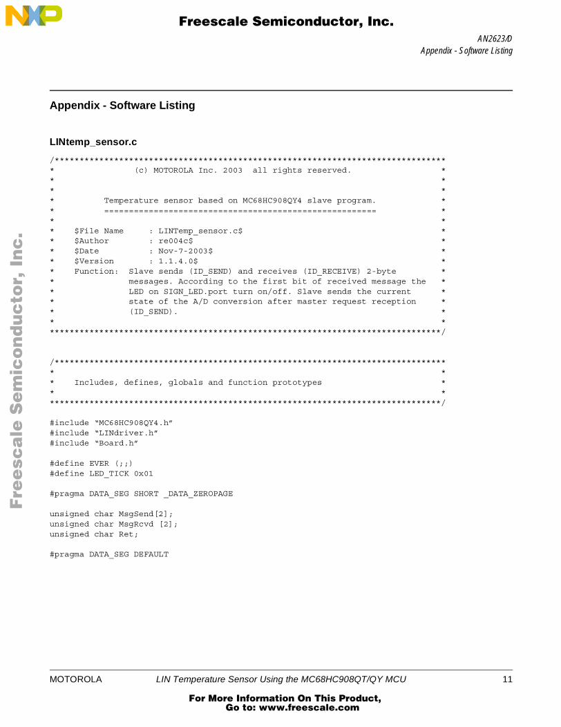
Appendix - Software Listing
LINtemp_sensor.c
/******************************************************************************** (c) MOTOROLA Inc. 2003 all rights reserved. ** ** ** Temperature sensor based on MC68HC908QY4 slave program. ** ======================================================= ** ** $File Name : LINTemp_sensor.c$ ** $Author : re004c$ ** $Date : Nov-7-2003$ ** $Version : 1.1.4.0$ ** Function: Slave sends (ID_SEND) and receives (ID_RECEIVE) 2-byte ** messages. According to the first bit of received message the ** LED on SIGN_LED.port turn on/off. Slave sends the current ** state of the A/D conversion after master request reception ** (ID_SEND). ** ********************************************************************************/
/******************************************************************************** ** Includes, defines, globals and function prototypes ** ********************************************************************************/
#include “MC68HC908QY4.h”#include “LINdriver.h”#include “Board.h”
#define EVER (;;)#define LED_TICK 0x01
#pragma DATA_SEG SHORT _DATA_ZEROPAGE
unsigned char MsgSend[2];unsigned char MsgRcvd [2];unsigned char Ret;
#pragma DATA_SEG DEFAULT
MOTOROLA LIN Temperature Sensor Using the MC68HC908QT/QY MCU 11
For More Information On This Product, Go to: www.freescale.com
AN2623/D
F
ree
sca
le S
em
ico
nd
uc
tor,
I
Freescale Semiconductor, Inc.n
c..
.
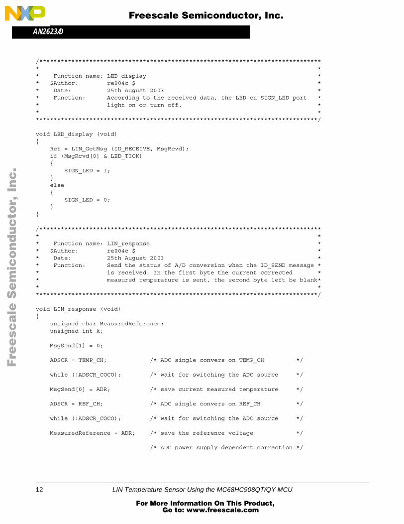
/******************************************************************************** ** Function name: LED_display ** $Author: re004c $ ** Date: 25th August 2003 ** Function: According to the received data, the LED on SIGN_LED port ** light on or turn off. ** ********************************************************************************/
void LED_display (void){ Ret = LIN_GetMsg (ID_RECEIVE, MsgRcvd); if (MsgRcvd[0] & LED_TICK) { SIGN_LED = 1; } else { SIGN_LED = 0; }}
/******************************************************************************** ** Function name: LIN_response ** $Author: re004c $ ** Date: 25th August 2003 ** Function: Send the status of A/D conversion when the ID_SEND message ** is received. In the first byte the current corrected ** measured temperature is sent, the second byte left be blank** ********************************************************************************/
void LIN_response (void){ unsigned char MeasuredReference; unsigned int k;
MsgSend[1] = 0;
ADSCR = TEMP_CH; /* ADC single convers on TEMP_CH */
while (!ADSCR_COCO); /* wait for switching the ADC source */
MsgSend[0] = ADR; /* save current measured temperature */
ADSCR = REF_CH; /* ADC single convers on REF_CH */
while (!ADSCR_COCO); /* wait for switching the ADC source */
MeasuredReference = ADR; /* save the reference voltage */
/* ADC power supply dependent correction */
12 LIN Temperature Sensor Using the MC68HC908QT/QY MCU
For More Information On This Product, Go to: www.freescale.com
AN2623/DAppendix - Software Listing
F
ree
sca
le S
em
ico
nd
uc
tor,
I
Freescale Semiconductor, Inc.n
c..
.
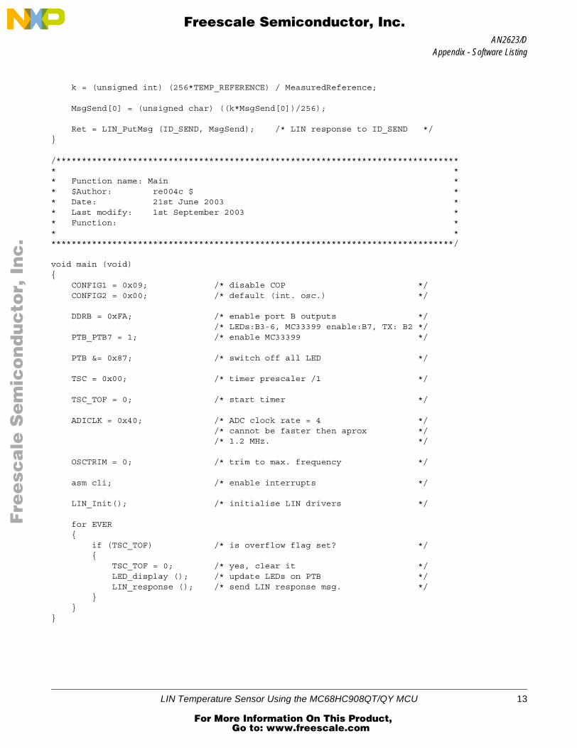
k = (unsigned int) (256*TEMP_REFERENCE) / MeasuredReference; MsgSend[0] = (unsigned char) ((k*MsgSend[0])/256);
Ret = LIN_PutMsg (ID_SEND, MsgSend); /* LIN response to ID_SEND */}
/******************************************************************************** ** Function name: Main ** $Author: re004c $ ** Date: 21st June 2003 ** Last modify: 1st September 2003 ** Function: ** ********************************************************************************/
void main (void) { CONFIG1 = 0x09; /* disable COP */ CONFIG2 = 0x00; /* default (int. osc.) */
DDRB = 0xFA; /* enable port B outputs */ /* LEDs:B3-6, MC33399 enable:B7, TX: B2 */ PTB_PTB7 = 1; /* enable MC33399 */
PTB &= 0x87; /* switch off all LED */
TSC = 0x00; /* timer prescaler /1 */
TSC_TOF = 0; /* start timer */
ADICLK = 0x40; /* ADC clock rate = 4 */ /* cannot be faster then aprox */ /* 1.2 MHz. */
OSCTRIM = 0; /* trim to max. frequency */
asm cli; /* enable interrupts */
LIN_Init(); /* initialise LIN drivers */
for EVER { if (TSC_TOF) /* is overflow flag set? */ { TSC_TOF = 0; /* yes, clear it */ LED_display (); /* update LEDs on PTB */ LIN_response (); /* send LIN response msg. */ } }}
LIN Temperature Sensor Using the MC68HC908QT/QY MCU 13
For More Information On This Product, Go to: www.freescale.com

AN2623/D
F
ree
sca
le S
em
ico
nd
uc
tor,
I
Freescale Semiconductor, Inc.n
c..
.
/******************************************************************************** Function: LIN_Command ** Description: User call-back. Called by the driver after transmission or ** reception of the Master Request Command Frame (ID: 0x3C). ********************************************************************************/ void LIN_Command(){ for EVER { }}
LINmsg.c
/******************************************************************************** Copyright (C) 2003 Motorola, Inc.* All Rights Reserved** Filename: $RCSfile: LINmsg.c,v $* Author: $Author: r57404 $* Locker: $Locker: $* State: $State: Exp $* Revision: $Revision: 1.3 $** Functions: LIN header file for message configuration** History: Use the RCS command log to display revision history* information.** Description: ** Notes: Users should alter this file to define the required LIN messages********************************************************************************/
//includes#include “LINdriver.h”
/*************** LIN Frame setup dependant variables **************************//* *//* This is where the user will define the frames used in the application *//* *//******************************************************************************/
//Define what messages will be used in the application, as “Message0xID”, where//ID is the message id in hex with the parity bits included.//Define the frame data field for each message - the data field can be 2, 4 or 8 //bytes long.
U8 volatile Message0x1A[2]; // id 0x1A = 0x1A with parity
14 LIN Temperature Sensor Using the MC68HC908QT/QY MCU
For More Information On This Product, Go to: www.freescale.com
AN2623/DAppendix - Software Listing
F
ree
sca
le S
em
ico
nd
uc
tor,
I
Freescale Semiconductor, Inc.n
c..
.
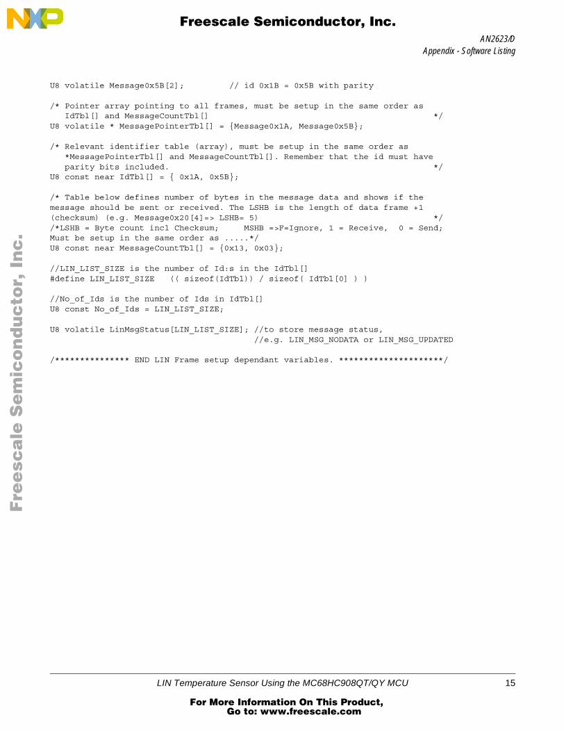
U8 volatile Message0x5B[2]; // id 0x1B = 0x5B with parity
/* Pointer array pointing to all frames, must be setup in the same order as IdTbl[] and MessageCountTbl[] */U8 volatile * MessagePointerTbl[] = {Message0x1A, Message0x5B};
/* Relevant identifier table (array), must be setup in the same order as *MessagePointerTbl[] and MessageCountTbl[]. Remember that the id must have parity bits included. */U8 const near IdTbl[] = { 0x1A, 0x5B};
/* Table below defines number of bytes in the message data and shows if the message should be sent or received. The LSHB is the length of data frame +1 (checksum) (e.g. Message0x20[4]=> LSHB= 5) *//*LSHB = Byte count incl Checksum; MSHB =>F=Ignore, 1 = Receive, 0 = Send;Must be setup in the same order as .....*/U8 const near MessageCountTbl[] = {0x13, 0x03};
//LIN_LIST_SIZE is the number of Id:s in the IdTbl[]#define LIN_LIST_SIZE (( sizeof(IdTbl)) / sizeof( IdTbl[0] ) )
//No_of_Ids is the number of Ids in IdTbl[]U8 const No_of_Ids = LIN_LIST_SIZE;
U8 volatile LinMsgStatus[LIN_LIST_SIZE]; //to store message status, //e.g. LIN_MSG_NODATA or LIN_MSG_UPDATED
/*************** END LIN Frame setup dependant variables. *********************/
LIN Temperature Sensor Using the MC68HC908QT/QY MCU 15
For More Information On This Product, Go to: www.freescale.com
AN2623/D
F
ree
sca
le S
em
ico
nd
uc
tor,
I
Freescale Semiconductor, Inc.n
c..
.
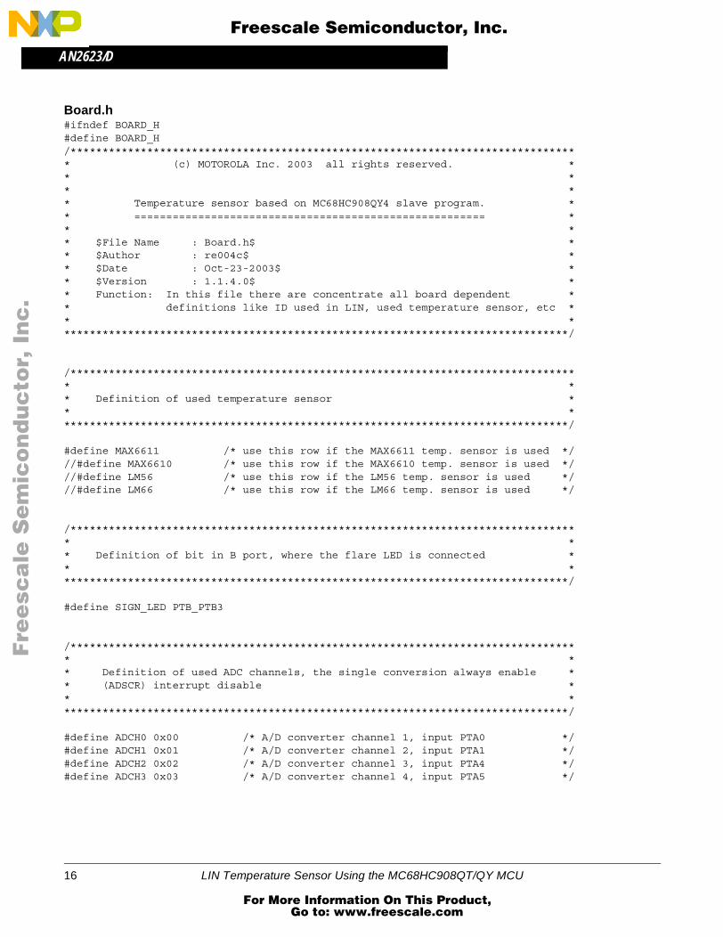
Board.h#ifndef BOARD_H#define BOARD_H/******************************************************************************** (c) MOTOROLA Inc. 2003 all rights reserved. ** ** ** Temperature sensor based on MC68HC908QY4 slave program. ** ======================================================= ** ** $File Name : Board.h$ ** $Author : re004c$ ** $Date : Oct-23-2003$ ** $Version : 1.1.4.0$ ** Function: In this file there are concentrate all board dependent ** definitions like ID used in LIN, used temperature sensor, etc ** ********************************************************************************/
/******************************************************************************** ** Definition of used temperature sensor ** ********************************************************************************/
#define MAX6611 /* use this row if the MAX6611 temp. sensor is used *///#define MAX6610 /* use this row if the MAX6610 temp. sensor is used *///#define LM56 /* use this row if the LM56 temp. sensor is used *///#define LM66 /* use this row if the LM66 temp. sensor is used */
/******************************************************************************** ** Definition of bit in B port, where the flare LED is connected ** ********************************************************************************/
#define SIGN_LED PTB_PTB3
/******************************************************************************** ** Definition of used ADC channels, the single conversion always enable ** (ADSCR) interrupt disable ** ********************************************************************************/
#define ADCH0 0x00 /* A/D converter channel 1, input PTA0 */#define ADCH1 0x01 /* A/D converter channel 2, input PTA1 */#define ADCH2 0x02 /* A/D converter channel 3, input PTA4 */#define ADCH3 0x03 /* A/D converter channel 4, input PTA5 */
16 LIN Temperature Sensor Using the MC68HC908QT/QY MCU
For More Information On This Product, Go to: www.freescale.com
AN2623/D
F
ree
sca
le S
em
ico
nd
uc
tor,
I
Freescale Semiconductor, Inc.n
c..
.
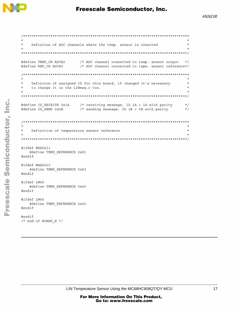
/******************************************************************************** ** Definiton of ADC channels where the temp. sensor is conected ** ********************************************************************************/
#define TEMP_CH ADCH2 /* ADC channel connected to temp. sensor output */#define REF_CH ADCH3 /* ADC channel connected to tepm. sensor reference*/
/******************************************************************************** ** Definiton of assigned ID for this board, if changed it’s necessary ** to change it in the LINmsg.c too. ** ********************************************************************************/
#define ID_RECEIVE 0x1A /* receiving message, ID 1A = 1A with parity */#define ID_SEND 0x5B /* sending message, ID 1B = 5B with parity */
/******************************************************************************** ** Definition of temperature sensor reference ** ********************************************************************************/
#ifdef MAX6611 #define TEMP_REFERENCE 0xD1#endif
#ifdef MAX6610 #define TEMP_REFERENCE 0x83#endif
#ifdef LM56 #define TEMP_REFERENCE 0x40#endif
#ifdef LM66 #define TEMP_REFERENCE 0x40#endif
#endif /* end of BOARD_H */
LIN Temperature Sensor Using the MC68HC908QT/QY MCU 17
For More Information On This Product, Go to: www.freescale.com

AN2623/D
F
ree
sca
le S
em
ico
nd
uc
tor,
I
Freescale Semiconductor, Inc.n
c..
.
18 LIN Temperature Sensor Using the MC68HC908QT/QY MCU
For More Information On This Product, Go to: www.freescale.com

AN2623/D
F
ree
sca
le S
em
ico
nd
uc
tor,
I
Freescale Semiconductor, Inc.n
c..
.
LIN Temperature Sensor Using the MC68HC908QT/QY MCU 19
For More Information On This Product, Go to: www.freescale.com

AN2623/D
Fre
esc
ale
Se
mic
on
du
cto
r, I
Freescale Semiconductor, Inc.
For More Information On This Product, Go to: www.freescale.com
nc
...