Embed Size (px)
Citation preview
Shock and Vibration 18 (2011) 709–726 709DOI 10.3233/SAV-2010-0593IOS Press
Free vibrations of a Reddy-Bickfordmulti-span beam carrying multiplespring-mass systems
Yusuf Yesilce∗Dokuz Eylul University, Civil Engineering Department, Eng. Fac., 35160, Buca, Izmir, Turkey
Received 21 August 2009
Revised 4 May 2010
Abstract. The structural elements supporting motors or engines are frequently seen in technological applications. The operationof machine may introduce additional dynamic stresses on the beam. It is important, then, to know the natural frequenciesof the coupled beam-mass system, in order to obtain a proper design of the structural elements. The literature regarding thefree vibration analysis of Bernoulli-Euler and Timoshenko single-span beams carrying a number of spring-mass system andmulti-span beams carrying multiple spring-mass systems are plenty, but the free vibration analysis of Reddy-Bickford multi-spanbeams carrying multiple spring-mass systems has not been investigated by any of the studies in open literature so far. Thispaper aims at determining the exact solutions for the natural frequencies and mode shapes of Reddy-Bickford beams. The modelallows analyzing the influence of the shear effect and spring-mass systems on the dynamic behavior of the beams by usingReddy-Bickford Beam Theory (RBT). The effects of attached spring-mass systems on the free vibration characteristics of the 1–4span beams are studied. The natural frequencies of Reddy-Bickford single-span and multi-span beams calculated by using thenumerical assembly technique and the secant method are compared with the natural frequencies of single-span and multi-spanbeams calculated by using Timoshenko Beam Theory (TBT); the mode shapes are presented in graphs.
Keywords: Eigenvalue problem, free vibration, numerical assembly technique, Reddy-Bickford multi-span beam, spring-masssystem
1. Introduction
The analysis of beams has been performed over the years mostly using Bernoulli-Euler beam theory (BET). Theclassical Bernoulli-Euler beam is well studied for slender beams, where the transverse shear deformation can besafely disregarded. This theory is based on the assumption that plain sections of the cross-section remain plain andperpendicular to the beam axis. The cross-sectional displacements of Bernoulli-Euler beam theory are shown in(Fig. 1.a) [1]. For moderately thick beams Bernoulli-Euler beam theory can be modified in order to take into accountthe transverse shear effect in a simplified way. For example, the well-known Timoshenko beam theory (TBT)predicts a uniform shear distribution, so necessitating the use of a so-called shear factor [2–5]. The cross-sectionaldisplacements of Timoshenko beam theory are shown in (Fig. 1.b). Han et al. presented a comprehensive study ofBernoulli-Euler, Rayleigh, Shear and Timoshenko beam theories [6].
The real shear deformation distribution is not uniform along the depth of the beam, so that Timoshenko beamtheory is not recommended for composite beams, where the accurate determination of the shear stresses is required.Especially, it was found that the Timoshenko shear deformation theory has some major numerical problems such as
∗Corresponding author. Tel.: +90 232 4127073; Fax: +90 232 4531191; E-mail: [email protected].
ISSN 1070-9622/11/$27.50 2011 – IOS Press and the authors. All rights reserved
710 Y. Yesilce / Free vibrations of a Reddy-Bickford multi-span beam carrying multiple spring-mass systems
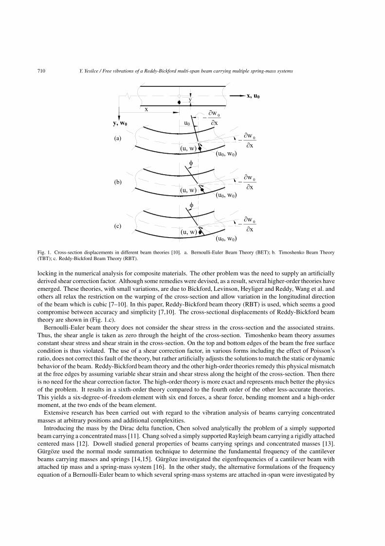
Fig. 1. Cross-section displacements in different beam theories [10]. a. Bernoulli-Euler Beam Theory (BET); b. Timoshenko Beam Theory(TBT); c. Reddy-Bickford Beam Theory (RBT).
locking in the numerical analysis for composite materials. The other problem was the need to supply an artificiallyderived shear correction factor. Although some remedies were devised, as a result, several higher-order theories haveemerged. These theories, with small variations, are due to Bickford, Levinson, Heyliger and Reddy, Wang et al. andothers all relax the restriction on the warping of the cross-section and allow variation in the longitudinal directionof the beam which is cubic [7–10]. In this paper, Reddy-Bickford beam theory (RBT) is used, which seems a goodcompromise between accuracy and simplicity [7,10]. The cross-sectional displacements of Reddy-Bickford beamtheory are shown in (Fig. 1.c).
Bernoulli-Euler beam theory does not consider the shear stress in the cross-section and the associated strains.Thus, the shear angle is taken as zero through the height of the cross-section. Timoshenko beam theory assumesconstant shear stress and shear strain in the cross-section. On the top and bottom edges of the beam the free surfacecondition is thus violated. The use of a shear correction factor, in various forms including the effect of Poisson’sratio, does not correct this fault of the theory, but rather artificially adjusts the solutions to match the static or dynamicbehavior of the beam. Reddy-Bickford beam theory and the other high-order theories remedy this physical mismatchat the free edges by assuming variable shear strain and shear stress along the height of the cross-section. Then thereis no need for the shear correction factor. The high-order theory is more exact and represents much better the physicsof the problem. It results in a sixth-order theory compared to the fourth order of the other less-accurate theories.This yields a six-degree-of-freedom element with six end forces, a shear force, bending moment and a high-ordermoment, at the two ends of the beam element.
Extensive research has been carried out with regard to the vibration analysis of beams carrying concentratedmasses at arbitrary positions and additional complexities.
Introducing the mass by the Dirac delta function, Chen solved analytically the problem of a simply supportedbeam carrying a concentratedmass [11]. Chang solved a simply supported Rayleigh beam carrying a rigidly attachedcentered mass [12]. Dowell studied general properties of beams carrying springs and concentrated masses [13].Gurgoze used the normal mode summation technique to determine the fundamental frequency of the cantileverbeams carrying masses and springs [14,15]. Gurgoze investigated the eigenfrequencies of a cantilever beam withattached tip mass and a spring-mass system [16]. In the other study, the alternative formulations of the frequencyequation of a Bernoulli-Euler beam to which several spring-mass systems are attached in-span were investigated by
Y. Yesilce / Free vibrations of a Reddy-Bickford multi-span beam carrying multiple spring-mass systems 711
Gurgoze [17]. Lin and Tsai investigated the free vibration analysis of a uniform Bernoulli-Euler multi-span beamcarrying multiple point masses and Bernoulli-Euler multiple-step beam carrying a number of intermediate lumpedmasses and rotary inertias [18,19]. In the other study, Lin and Tsai determined the natural frequencies and modeshapes of Bernoulli-Euler multi-span beam carrying multiple spring-mass systems [20]. Wu determined the naturalfrequencies and mode shapes of a uniform Bernoulli-Euler cantilever beam carrying any number of spring-masssystems by using the conventional finite element method and the equivalent mass method [21]. Liu et al. formulatedthe frequency equation for beams carrying intermediate concentrated masses by using the Laplace TransformationTechnique [22]. Wu and Chou obtained the exact solution of the natural frequency values and mode shapes for abeam carrying any number of spring masses [23]. Naguleswaran obtained the natural frequency values of the beamson up to five resilient supports including ends and carrying several particles by using BET obtained a fourth-orderdeterminant equated to zero [24,25]. Zhou studied the free vibration of multi-span Timoshenko beams by usingRayleigh-Ritz method [26]. He developed the static Timoshenko beam functions which are composed of a set oftransverse deflection functions and a set of rotational angle functions as the trial functions. Wu and Chen performedthe free vibration analysis of a uniform Timoshenko beam carrying multiple spring-mass systems by using numericalassembly method [27]. Lin and Chang studied the free vibration analysis of a multi-span Timoshenko beam withan arbitrary number of flexible constraints by considering the compatibility requirements on each constraint pointand using a transfer matrix method [28]. Wang et al. studied the natural frequencies and mode shapes of a uniformTimoshenko beam carrying multiple intermediate spring-mass systems with the effects of shear deformation androtatory inertia [29]. Yesilce and Demirdag investigated the effect of axial force on free vibration of Timoshenkomulti-span beam carrying multiple spring-mass systems [30]. Other studies on the vibration analysis of beamscarrying masses are presented in references [31,32].
2. The mathematical model and formulation
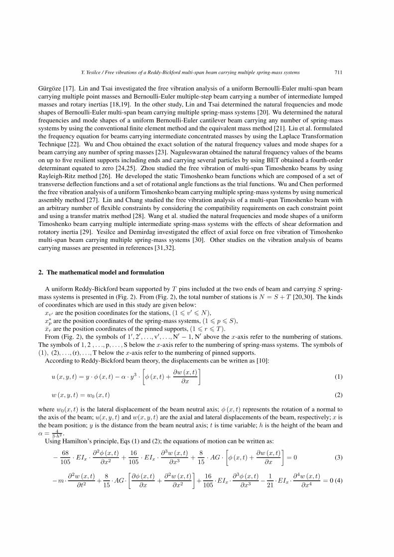
A uniform Reddy-Bickford beam supported by T pins included at the two ends of beam and carrying S spring-mass systems is presented in (Fig. 2). From (Fig. 2), the total number of stations is N = S + T [20,30]. The kindsof coordinates which are used in this study are given below:
xv′ are the position coordinates for the stations, (1 � v′ � N),x∗
p are the position coordinates of the spring-mass systems, (1 � p � S),xr are the position coordinates of the pinned supports, (1 � r � T ).From (Fig. 2), the symbols of 1′, 2′, . . ., v′, . . ., N′ − 1, N′ above the x-axis refer to the numbering of stations.
The symbols of 1, 2 , . . ., p, . . . , S below the x-axis refer to the numbering of spring-mass systems. The symbols of(1), (2), . . ., (r), . . ., T below the x-axis refer to the numbering of pinned supports.
According to Reddy-Bickford beam theory, the displacements can be written as [10]:
u (x, y, t) = y · φ (x, t) − α · y3 ·[φ (x, t) +
∂w (x, t)∂x
](1)
w (x, y, t) = w0 (x, t) (2)
where w0(x, t) is the lateral displacement of the beam neutral axis; φ (x, t) represents the rotation of a normal tothe axis of the beam; u(x, y, t) and w(x, y, t) are the axial and lateral displacements of the beam, respectively; x isthe beam position; y is the distance from the beam neutral axis; t is time variable; h is the height of the beam andα = 4
3·h2 .Using Hamilton’s principle, Eqs (1) and (2); the equations of motion can be written as:
− 68105
· EIx · ∂2φ (x, t)∂x2
+16105
· EIx · ∂3w (x, t)∂x3
+815
· AG ·[φ (x, t) +
∂w (x, t)∂x
]= 0 (3)
−m · ∂2w (x, t)
∂t2+
815
·AG ·[∂φ (x, t)
∂x+
∂2w (x, t)∂x2
]+
16105
·EIx · ∂3φ (x, t)∂x3
− 121
·EIx · ∂4w (x, t)∂x4
= 0 (4)
712 Y. Yesilce / Free vibrations of a Reddy-Bickford multi-span beam carrying multiple spring-mass systems
Fig. 2. A Reddy-Bickford uniform beam supported by T pins and carrying S spring-mass systems.
where φ (x, t) represents the rotation of a normal to the axis of the beam, m is mass per unit length of the beam, L islength of the beam, A is the cross-section area, Ix is moment of inertia, E, G are Young’s modulus and shear modulusof the beam, respectively, x is the beam position coordinate, t is time variable. The details for the application ofHamilton’s principle and the derivation of the equations of motion are presented in Section “Appendix-A” at the endof the paper.
The pth spring-mass system’s equation of motion can be written as:
mp · zp + kp · (zp − wp) = 0 (5)
where mp is the mass of the pth spring-mass system, kp is the spring constant of the pth spring-mass system, zp
and zp are the acceleration and displacement of the pth spring-mass system relative to its static equilibrium position,respectively, wp is the transverse displacement of the beam at the attaching point of the pth spring-mass system.
Assuming that the motion is harmonic we substitute for w(z, t) and φ (z, t) the following:
w (z, t) = w (z) · sin (ω · t) (6)
φ (z, t) = φ (z) · sin (ω · t) (7)
zp = Zp · sin (ω · t) (8)
and obtain a system of two coupled ordinary differential equations as:
Y. Yesilce / Free vibrations of a Reddy-Bickford multi-span beam carrying multiple spring-mass systems 713
− 68105
· EIx
L2· d2φ (z)
dz2+
16105
· EIx
L3· d3w (z)
dz3+
815
· AG ·[φ (z) +
1L
· dw (z)dz
]= 0 (9)
m · ω2 · w (z)+815
· AG
L·[dφ (z)
dz+
1L
· d2w (z)dz2
]+
16105
· EIx
L3· d3φ (z)
dz3− 1
21· EIx
L4· d4w (z)
dz4= 0 (10)
where z = xL and ω is natural frequency of the beam systems.
It is assumed that the solutions are:
w (z) = C · eisz (11)
φ (z) = P · eisz (12)
and substituting Eqs (11) and (12) into Eqs (9) and (10) results in(815
· AG +68105
· EIx
L2· s2
)· P +
(815
· AG
L· s · i − 16
105· EIx
L3· s3 · i
)· C = 0 (13)(
815
· AG
L· s · i − 16
105· EIx
L3· s3 · i
)· P +
(m · ω2 − 8
15· AG
L2· s2 − 1
21· EIx
L4· s4
)· C = 0 (14)
Equations (13) and (14) can be written in matrix form for the two unknownsP and C as⎡⎢⎢⎣
815
· AG +68105
· EIx
L2· s2
815
· AG
L· s · i − 16
105· EIx
L3· s3 · i
815
· AG
L· s · i − 16
105· EIx
L3· s3 · i m · ω2 − 8
15· AG
L2· s2 − 1
21· EIx
L4· s4
⎤⎥⎥⎦ ·
⎧⎨⎩
P
C
⎫⎬⎭ =
⎧⎨⎩
0
0
⎫⎬⎭ (15)
and a non-trivial solution will be obtained when the determinant of the coefficient matrix will be zero, i.e.[− 4
525· (EIx)2
L6
]· s6−
(815
· AG · EIx
L4
)· s4+
(68105
· EIx
L2· m · ω2
)· s2+
815
· AG · m · ω2 =0 (16)
Thus, there is a sixth-degree polynomialwith the unknowns, resulting in six values and the transverse displacementfunction can be written as:
w (z, t) =[C1 · eis1z + C2 · eis2z + C3 · eis3z + C4 · eis4z + C5 · eis5z + C6 · eis6z
] · sin (ω · t) (17)
The expression for bending rotation w′ (z, t) is given by
w′ (z, t) =1L
· dw (z)dz
· sin (ω · t) (18)
By using Eq. (17), the rotation of normal φ (z, t) can be obtained as:
φ (z, t)=−(
γ ·m·ω2+1L
)· dw (z)
dz·sin (ω ·t)− 3
2· β
L3· d
3w (z)dz3
·sin (ω ·t)+ 17784
· β2
L5· d
5w (z)dz5
·sin (ω ·t) (19)
where
β =EIx
AG(20a)
γ =1445784
· β
AG(20b)
The shear force function Q(z, t) can be obtained by using Eqs (17) and (19) as:
Q (z, t) =[−8 · AG
15·(
φ (z) +1L
· dw (z)dz
)+
EIx
21 · L3· d3w (z)
dz3− 16 · EIx
105 · L2· d2φ (z)
dz2
]· sin (ω · t) (21)
Similarly, the bending moment function M(z, t) can be obtained by using Eqs (17) and (19) as:
M (z, t) =(− EIx
21 · L2· d2w (z)
dz2+
16 · EIx
105 · L · dφ (z)dz
)· sin (ω · t) (22)
The higher-order moment function Mh(z, t) can be obtained as:
Mh (z, t) =(
16 · EIx
105 · L2· d2w (z)
dz2− 68 · EIx
105 · L · dφ (z)dz
)· sin (ω · t) (23)
714 Y. Yesilce / Free vibrations of a Reddy-Bickford multi-span beam carrying multiple spring-mass systems
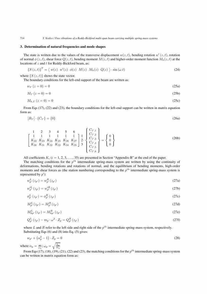
3. Determination of natural frequencies and mode shapes
The state is written due to the values of the transverse displacement w(z, t), bending rotation w′ (z, t), rotationof normal φ (z, t), shear force Q(z, t), bending moment M(z, t) and higher-order moment function Mh(z, t) at thelocations of z and t for Reddy-Bickford beam, as:
{S (z, t)}T =⟨
w(z) w′(z) φ(z) M(z) Mh(z) Q(z)⟩ · sin (ω.t) (24)
where {S (z, t)} shows the state vector.The boundary conditions for the left-end support of the beam are written as:
w1′ (z = 0) = 0 (25a)
M1′ (z = 0) = 0 (25b)
Mh,1′ (z = 0) = 0 (25c)
From Eqs (17), (22) and (23), the boundary conditions for the left-end support can be written in matrix equationform as:
[B1′ ] · {C1′} = {0} (26a)
1 2 3 4 5 6⎡⎣ 1 1 1 1 1 1
K22 K23 K24 K25 K26 K27
K30 K31 K32 K33 K34 K35
⎤⎦ 1
23·
⎧⎪⎪⎪⎪⎪⎪⎨⎪⎪⎪⎪⎪⎪⎩
C1′,1C1′,2C1′,3C1′,4C1′,5C1′,6
⎫⎪⎪⎪⎪⎪⎪⎬⎪⎪⎪⎪⎪⎪⎭
=
⎧⎨⎩
000
⎫⎬⎭ (26b)
All coefficients Ki (i = 1, 2, 3, . . . , 35) are presented in Section “Appendix-B” at the end of the paper.The matching conditions for the pth intermediate spring-mass system are written by using the continuity of
deformations, bending rotations and rotations of normal, and the equilibrium of bending moments, high-ordermoments and shear forces as (the station numbering corresponding to the pth intermediate spring-mass system isrepresented by p′):
wLp′ (zp′) = wR
p′ (zp′) (27a)
w′Lp′ (zp′) = w′R
p′ (zp′) (27b)
φLp′ (zp′) = φR
p′ (zp′) (27c)
MLp′ (zp′) = MR
p′ (zp′) (27d)
MLhp′ (zp′) = MR
hp′ (zp′) (27e)
QLp′ (zp′) − mp · ω2 · Zp = QR
p′ (zp′) (27f)
where L and R refer to the left side and right side of the pth intermediate spring-mass system, respectively.Substituting Eqs (6) and (8) into Eq. (5) gives:
wp′ +(α2
p − 1) · Zp = 0 (28)
where αp = ωωp
; ωp =√
kp
mp
From Eqs (17), (18), (19), (21), (22) and (23), the matching conditions for the pth intermediate spring-mass systemcan be written in matrix equation form as:
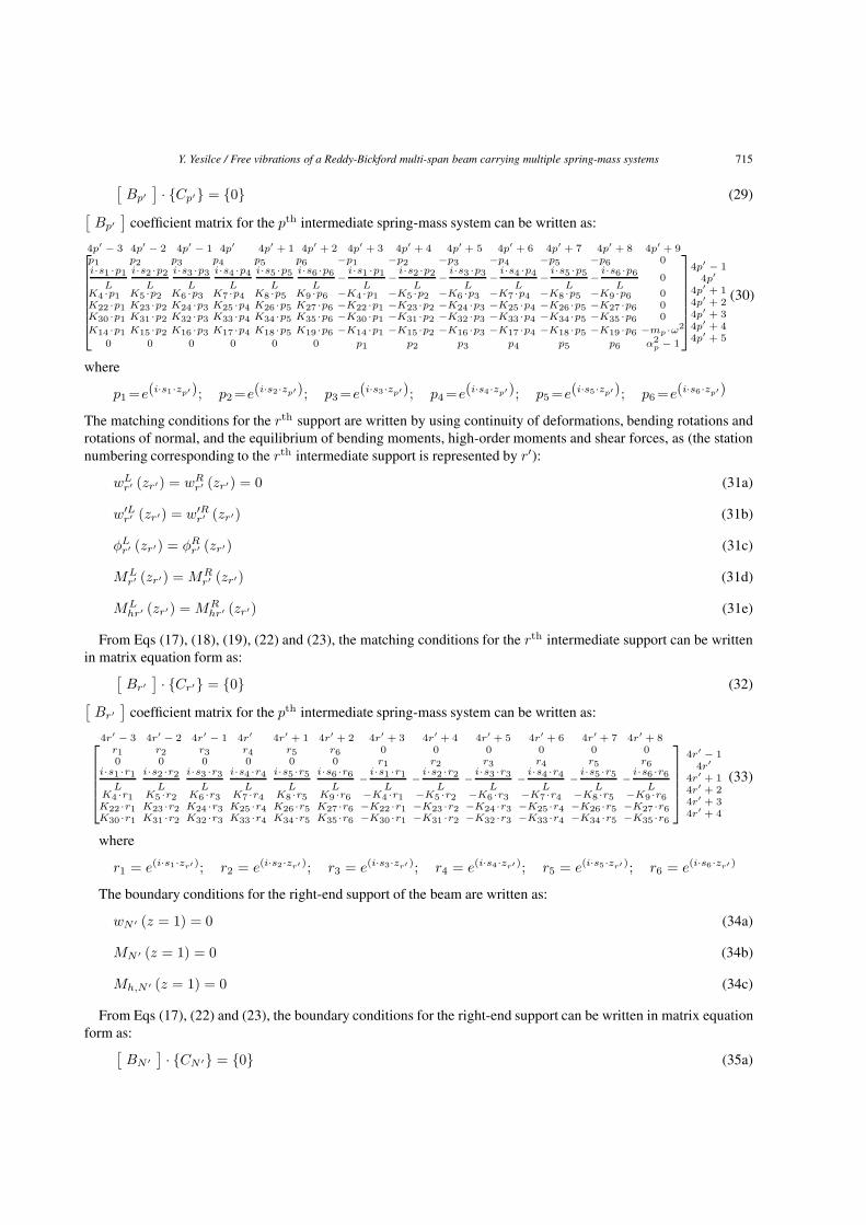
Y. Yesilce / Free vibrations of a Reddy-Bickford multi-span beam carrying multiple spring-mass systems 715
[Bp′
] · {Cp′} = {0} (29)[Bp′
]coefficient matrix for the pth intermediate spring-mass system can be written as:
4p′ − 3 4p′ − 2 4p′ − 1 4p′ 4p′ + 1 4p′ + 2 4p′ + 3 4p′ + 4 4p′ + 5 4p′ + 6 4p′ + 7 4p′ + 8 4p′ + 9⎡⎢⎢⎢⎢⎢⎣
p1 p2 p3 p4 p5 p6 −p1 −p2 −p3 −p4 −p5 −p6 0i·s1 ·p1
L
i·s2 ·p2
L
i·s3 ·p3
L
i·s4 ·p4
L
i·s5 ·p5
L
i·s6 ·p6
L− i·s1 ·p1
L− i·s2 ·p2
L− i·s3 ·p3
L− i·s4 ·p4
L− i·s5 ·p5
L− i·s6 ·p6
L0
K4 ·p1 K5 ·p2 K6 ·p3 K7 ·p4 K8 ·p5 K9 ·p6 −K4 ·p1 −K5 ·p2 −K6 ·p3 −K7 ·p4 −K8 ·p5 −K9 ·p6 0K22 ·p1 K23 ·p2 K24 ·p3 K25 ·p4 K26 ·p5 K27 ·p6 −K22 ·p1 −K23 ·p2 −K24 ·p3 −K25 ·p4 −K26 ·p5 −K27 ·p6 0K30 ·p1 K31 ·p2 K32 ·p3 K33 ·p4 K34 ·p5 K35 ·p6 −K30 ·p1 −K31 ·p2 −K32 ·p3 −K33 ·p4 −K34 ·p5 −K35 ·p6 0
K14 ·p1 K15 ·p2 K16 ·p3 K17 ·p4 K18 ·p5 K19 ·p6 −K14 ·p1 −K15 ·p2 −K16 ·p3 −K17 ·p4 −K18 ·p5 −K19 ·p6 −mp ·ω2
0 0 0 0 0 0 p1 p2 p3 p4 p5 p6 α2p − 1
⎤⎥⎥⎥⎥⎥⎦
4p′ − 14p′
4p′ + 14p′ + 24p′ + 34p′ + 44p′ + 5
(30)
where
p1 =e(i·s1·zp′); p2 =e(i·s2·zp′); p3 =e(i·s3·zp′); p4 =e(i·s4·zp′); p5 =e(i·s5·zp′); p6 =e(i·s6·zp′)
The matching conditions for the rth support are written by using continuity of deformations, bending rotations androtations of normal, and the equilibrium of bending moments, high-order moments and shear forces, as (the stationnumbering corresponding to the rth intermediate support is represented by r′):
wLr′ (zr′) = wR
r′ (zr′) = 0 (31a)
w′Lr′ (zr′) = w′R
r′ (zr′) (31b)
φLr′ (zr′) = φR
r′ (zr′) (31c)
MLr′ (zr′) = MR
r′ (zr′) (31d)
MLhr′ (zr′) = MR
hr′ (zr′) (31e)
From Eqs (17), (18), (19), (22) and (23), the matching conditions for the rth intermediate support can be writtenin matrix equation form as:[
Br′] · {Cr′} = {0} (32)[
Br′]
coefficient matrix for the pth intermediate spring-mass system can be written as:
4r′ − 3 4r′ − 2 4r′ − 1 4r′ 4r′ + 1 4r′ + 2 4r′ + 3 4r′ + 4 4r′ + 5 4r′ + 6 4r′ + 7 4r′ + 8⎡⎢⎢⎢⎣
r1 r2 r3 r4 r5 r6 0 0 0 0 0 00 0 0 0 0 0 r1 r2 r3 r4 r5 r6
i·s1 ·r1
L
i·s2 ·r2
L
i·s3 ·r3
L
i·s4 ·r4
L
i·s5 ·r5
L
i·s6 ·r6
L− i·s1 ·r1
L− i·s2 ·r2
L− i·s3 ·r3
L− i·s4 ·r4
L− i·s5 ·r5
L− i·s6 ·r6
LK4 ·r1 K5 ·r2 K6 ·r3 K7 ·r4 K8 ·r5 K9 ·r6 −K4 ·r1 −K5 ·r2 −K6 ·r3 −K7 ·r4 −K8 ·r5 −K9 ·r6K22 ·r1 K23 ·r2 K24 ·r3 K25 ·r4 K26 ·r5 K27 ·r6 −K22 ·r1 −K23 ·r2 −K24 ·r3 −K25 ·r4 −K26 ·r5 −K27 ·r6K30 ·r1 K31 ·r2 K32 ·r3 K33 ·r4 K34 ·r5 K35 ·r6 −K30 ·r1 −K31 ·r2 −K32 ·r3 −K33 ·r4 −K34 ·r5 −K35 ·r6
⎤⎥⎥⎥⎦
4r′ − 14r′
4r′ + 14r′ + 24r′ + 34r′ + 4
(33)
where
r1 = e(i·s1·zr′); r2 = e(i·s2·zr′ ); r3 = e(i·s3·zr′ ); r4 = e(i·s4·zr′); r5 = e(i·s5·zr′); r6 = e(i·s6·zr′ )
The boundary conditions for the right-end support of the beam are written as:
wN ′ (z = 1) = 0 (34a)
MN ′ (z = 1) = 0 (34b)
Mh,N ′ (z = 1) = 0 (34c)
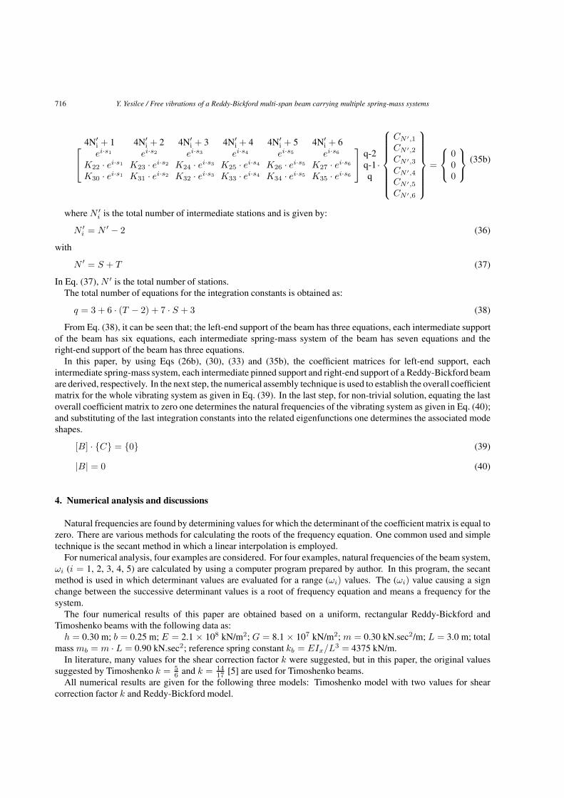
From Eqs (17), (22) and (23), the boundary conditions for the right-end support can be written in matrix equationform as:[
BN ′] · {CN ′} = {0} (35a)
716 Y. Yesilce / Free vibrations of a Reddy-Bickford multi-span beam carrying multiple spring-mass systems
4N′i + 1 4N′
i + 2 4N′i + 3 4N′
i + 4 4N′i + 5 4N′
i + 6⎡⎣ ei·s1 ei·s2 ei·s3 ei·s4 ei·s5 ei·s6
K22 · ei·s1 K23 · ei·s2 K24 · ei·s3 K25 · ei·s4 K26 · ei·s5 K27 · ei·s6
K30 · ei·s1 K31 · ei·s2 K32 · ei·s3 K33 · ei·s4 K34 · ei·s5 K35 · ei·s6
⎤⎦ q-2
q-1q
·
⎧⎪⎪⎪⎪⎪⎪⎨⎪⎪⎪⎪⎪⎪⎩
CN ′,1CN ′,2CN ′,3CN ′,4CN ′,5CN ′,6
⎫⎪⎪⎪⎪⎪⎪⎬⎪⎪⎪⎪⎪⎪⎭
=
⎧⎨⎩
000
⎫⎬⎭ (35b)
where N ′i is the total number of intermediate stations and is given by:
N ′i = N ′ − 2 (36)
with
N ′ = S + T (37)
In Eq. (37), N ′ is the total number of stations.The total number of equations for the integration constants is obtained as:
q = 3 + 6 · (T − 2) + 7 · S + 3 (38)
From Eq. (38), it can be seen that; the left-end support of the beam has three equations, each intermediate supportof the beam has six equations, each intermediate spring-mass system of the beam has seven equations and theright-end support of the beam has three equations.
In this paper, by using Eqs (26b), (30), (33) and (35b), the coefficient matrices for left-end support, eachintermediate spring-mass system, each intermediate pinned support and right-end support of a Reddy-Bickford beamare derived, respectively. In the next step, the numerical assembly technique is used to establish the overall coefficientmatrix for the whole vibrating system as given in Eq. (39). In the last step, for non-trivial solution, equating the lastoverall coefficient matrix to zero one determines the natural frequencies of the vibrating system as given in Eq. (40);and substituting of the last integration constants into the related eigenfunctions one determines the associated modeshapes.
[B] · {C} = {0} (39)
|B| = 0 (40)
4. Numerical analysis and discussions
Natural frequencies are found by determining values for which the determinant of the coefficient matrix is equal tozero. There are various methods for calculating the roots of the frequency equation. One common used and simpletechnique is the secant method in which a linear interpolation is employed.
For numerical analysis, four examples are considered. For four examples, natural frequencies of the beam system,ωi (i = 1, 2, 3, 4, 5) are calculated by using a computer program prepared by author. In this program, the secantmethod is used in which determinant values are evaluated for a range (ωi) values. The (ωi) value causing a signchange between the successive determinant values is a root of frequency equation and means a frequency for thesystem.
The four numerical results of this paper are obtained based on a uniform, rectangular Reddy-Bickford andTimoshenko beams with the following data as:
h = 0.30 m; b = 0.25 m; E = 2.1 × 10⁸ kN/m2; G = 8.1 × 10⁷ kN/m2; m = 0.30 kN.sec2/m; L = 3.0 m; totalmass mb = m · L = 0.90 kN.sec2; reference spring constant kb = EIx/L3 = 4375 kN/m.
In literature, many values for the shear correction factor k were suggested, but in this paper, the original valuessuggested by Timoshenko k = 5
6 and k = 1417 [5] are used for Timoshenko beams.
All numerical results are given for the following three models: Timoshenko model with two values for shearcorrection factor k and Reddy-Bickford model.
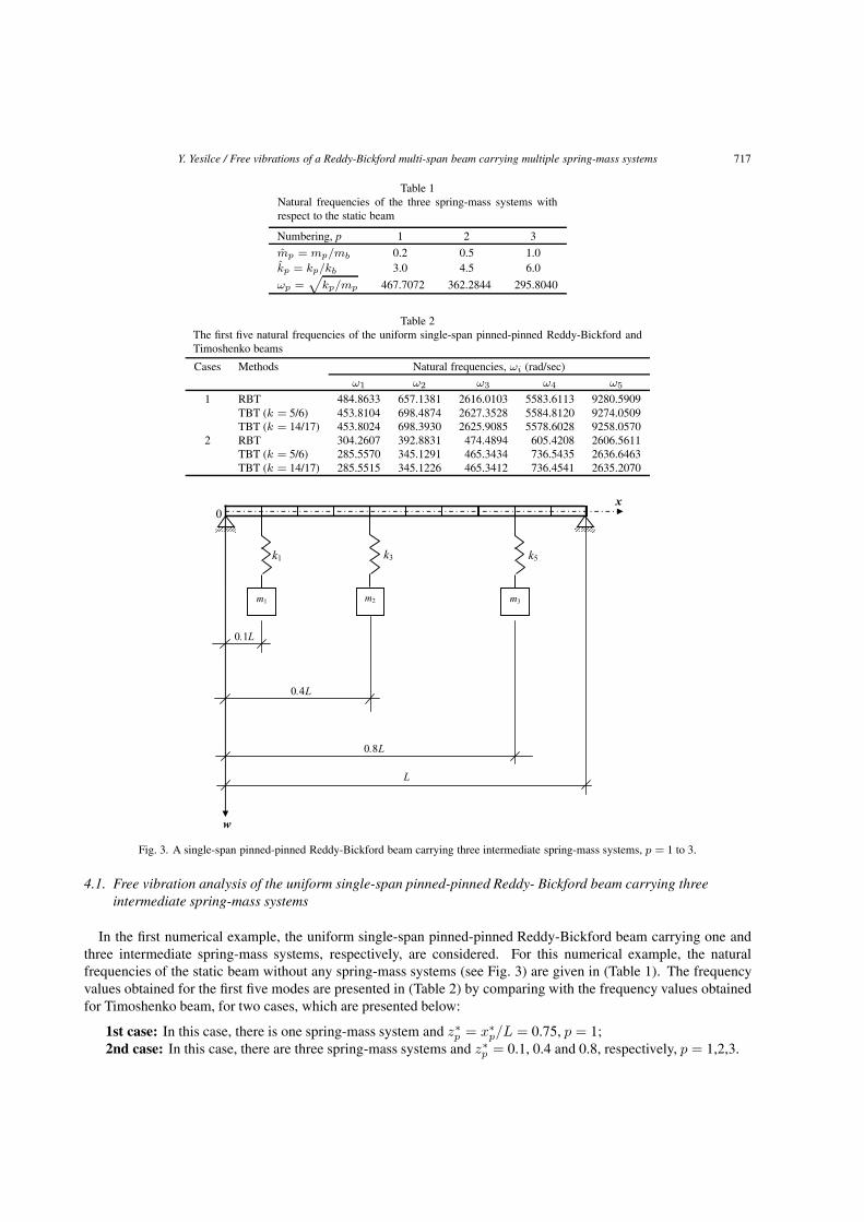
Y. Yesilce / Free vibrations of a Reddy-Bickford multi-span beam carrying multiple spring-mass systems 717
Table 1Natural frequencies of the three spring-mass systems withrespect to the static beam
Numbering, p 1 2 3
mp = mp/mb 0.2 0.5 1.0kp = kp/kb 3.0 4.5 6.0
ωp =√
kp/mp 467.7072 362.2844 295.8040
Table 2The first five natural frequencies of the uniform single-span pinned-pinned Reddy-Bickford andTimoshenko beams
Cases Methods Natural frequencies, ωi (rad/sec)ω1 ω2 ω3 ω4 ω5
1 RBT 484.8633 657.1381 2616.0103 5583.6113 9280.5909TBT (k = 5/6) 453.8104 698.4874 2627.3528 5584.8120 9274.0509TBT (k = 14/17) 453.8024 698.3930 2625.9085 5578.6028 9258.0570
2 RBT 304.2607 392.8831 474.4894 605.4208 2606.5611TBT (k = 5/6) 285.5570 345.1291 465.3434 736.5435 2636.6463TBT (k = 14/17) 285.5515 345.1226 465.3412 736.4541 2635.2070
Fig. 3. A single-span pinned-pinned Reddy-Bickford beam carrying three intermediate spring-mass systems, p = 1 to 3.
4.1. Free vibration analysis of the uniform single-span pinned-pinned Reddy- Bickford beam carrying threeintermediate spring-mass systems
In the first numerical example, the uniform single-span pinned-pinned Reddy-Bickford beam carrying one andthree intermediate spring-mass systems, respectively, are considered. For this numerical example, the naturalfrequencies of the static beam without any spring-mass systems (see Fig. 3) are given in (Table 1). The frequencyvalues obtained for the first five modes are presented in (Table 2) by comparing with the frequency values obtainedfor Timoshenko beam, for two cases, which are presented below:
1st case: In this case, there is one spring-mass system and z∗p = x∗p/L = 0.75, p = 1;
2nd case: In this case, there are three spring-mass systems and z∗p = 0.1, 0.4 and 0.8, respectively, p = 1,2,3.
718 Y. Yesilce / Free vibrations of a Reddy-Bickford multi-span beam carrying multiple spring-mass systems
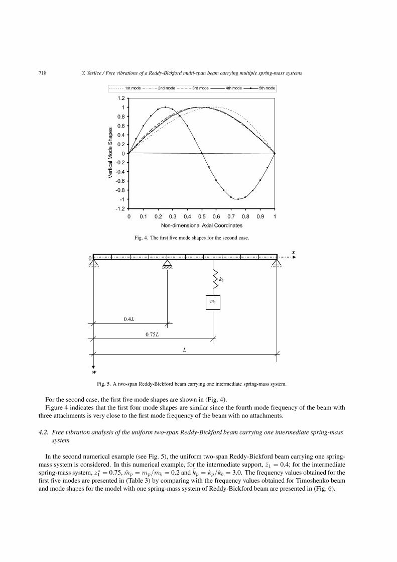
Fig. 4. The first five mode shapes for the second case.
Fig. 5. A two-span Reddy-Bickford beam carrying one intermediate spring-mass system.
For the second case, the first five mode shapes are shown in (Fig. 4).Figure 4 indicates that the first four mode shapes are similar since the fourth mode frequency of the beam with
three attachments is very close to the first mode frequency of the beam with no attachments.
4.2. Free vibration analysis of the uniform two-span Reddy-Bickford beam carrying one intermediate spring-masssystem
In the second numerical example (see Fig. 5), the uniform two-span Reddy-Bickford beam carrying one spring-mass system is considered. In this numerical example, for the intermediate support, z1 = 0.4; for the intermediatespring-mass system, z∗1 = 0.75, mp = mp/mb = 0.2 and kp = kp/kb = 3.0. The frequency values obtained for thefirst five modes are presented in (Table 3) by comparing with the frequency values obtained for Timoshenko beamand mode shapes for the model with one spring-mass system of Reddy-Bickford beam are presented in (Fig. 6).
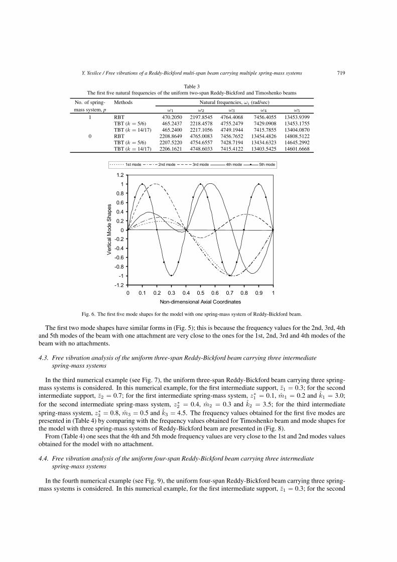
Y. Yesilce / Free vibrations of a Reddy-Bickford multi-span beam carrying multiple spring-mass systems 719
Table 3The first five natural frequencies of the uniform two-span Reddy-Bickford and Timoshenko beams
No. of spring- Methods Natural frequencies, ωi (rad/sec)mass system, p ω1 ω2 ω3 ω4 ω5
1 RBT 470.2050 2197.8545 4764.4068 7456.4055 13453.9399TBT (k = 5/6) 465.2437 2218.4578 4755.2479 7429.0908 13453.1755TBT (k = 14/17) 465.2400 2217.1056 4749.1944 7415.7855 13404.0870
0 RBT 2208.8649 4765.0083 7456.7652 13454.4826 14808.5122TBT (k = 5/6) 2207.5220 4754.6557 7428.7194 13434.6323 14645.2992TBT (k = 14/17) 2206.1621 4748.6033 7415.4122 13403.5425 14601.6668
Fig. 6. The first five mode shapes for the model with one spring-mass system of Reddy-Bickford beam.
The first two mode shapes have similar forms in (Fig. 5); this is because the frequency values for the 2nd, 3rd, 4thand 5th modes of the beam with one attachment are very close to the ones for the 1st, 2nd, 3rd and 4th modes of thebeam with no attachments.
4.3. Free vibration analysis of the uniform three-span Reddy-Bickford beam carrying three intermediatespring-mass systems
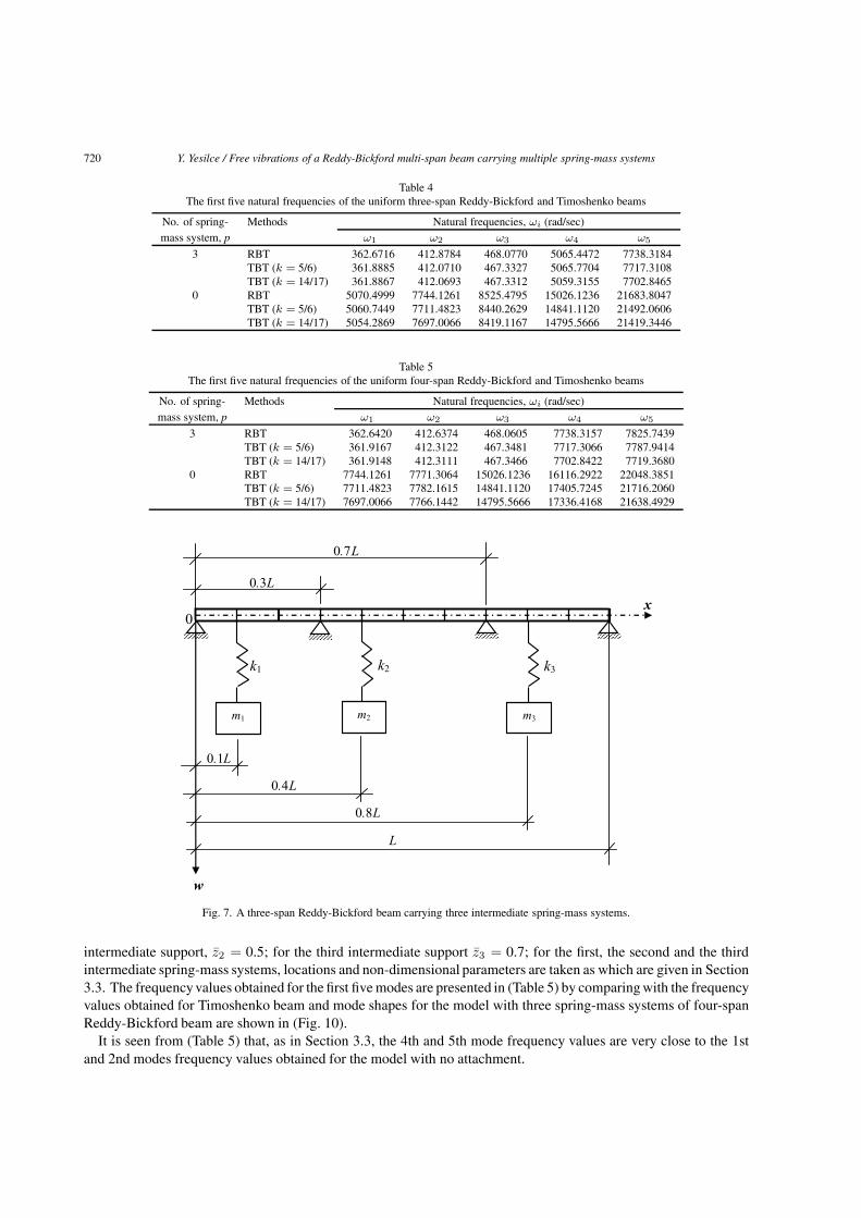
In the third numerical example (see Fig. 7), the uniform three-span Reddy-Bickford beam carrying three spring-mass systems is considered. In this numerical example, for the first intermediate support, z1 = 0.3; for the secondintermediate support, z2 = 0.7; for the first intermediate spring-mass system, z∗1 = 0.1, m1 = 0.2 and k1 = 3.0;for the second intermediate spring-mass system, z∗2 = 0.4, m2 = 0.3 and k2 = 3.5; for the third intermediatespring-mass system, z∗3 = 0.8, m3 = 0.5 and k3 = 4.5. The frequency values obtained for the first five modes arepresented in (Table 4) by comparing with the frequency values obtained for Timoshenko beam and mode shapes forthe model with three spring-mass systems of Reddy-Bickford beam are presented in (Fig. 8).
From (Table 4) one sees that the 4th and 5th mode frequency values are very close to the 1st and 2nd modes valuesobtained for the model with no attachment.
4.4. Free vibration analysis of the uniform four-span Reddy-Bickford beam carrying three intermediatespring-mass systems
In the fourth numerical example (see Fig. 9), the uniform four-span Reddy-Bickford beam carrying three spring-mass systems is considered. In this numerical example, for the first intermediate support, z1 = 0.3; for the second
720 Y. Yesilce / Free vibrations of a Reddy-Bickford multi-span beam carrying multiple spring-mass systems
Table 4The first five natural frequencies of the uniform three-span Reddy-Bickford and Timoshenko beams
No. of spring- Methods Natural frequencies, ωi (rad/sec)mass system, p ω1 ω2 ω3 ω4 ω5
3 RBT 362.6716 412.8784 468.0770 5065.4472 7738.3184TBT (k = 5/6) 361.8885 412.0710 467.3327 5065.7704 7717.3108TBT (k = 14/17) 361.8867 412.0693 467.3312 5059.3155 7702.8465
0 RBT 5070.4999 7744.1261 8525.4795 15026.1236 21683.8047TBT (k = 5/6) 5060.7449 7711.4823 8440.2629 14841.1120 21492.0606TBT (k = 14/17) 5054.2869 7697.0066 8419.1167 14795.5666 21419.3446
Table 5The first five natural frequencies of the uniform four-span Reddy-Bickford and Timoshenko beams
No. of spring- Methods Natural frequencies, ωi (rad/sec)mass system, p ω1 ω2 ω3 ω4 ω5
3 RBT 362.6420 412.6374 468.0605 7738.3157 7825.7439TBT (k = 5/6) 361.9167 412.3122 467.3481 7717.3066 7787.9414TBT (k = 14/17) 361.9148 412.3111 467.3466 7702.8422 7719.3680
0 RBT 7744.1261 7771.3064 15026.1236 16116.2922 22048.3851TBT (k = 5/6) 7711.4823 7782.1615 14841.1120 17405.7245 21716.2060TBT (k = 14/17) 7697.0066 7766.1442 14795.5666 17336.4168 21638.4929
Fig. 7. A three-span Reddy-Bickford beam carrying three intermediate spring-mass systems.
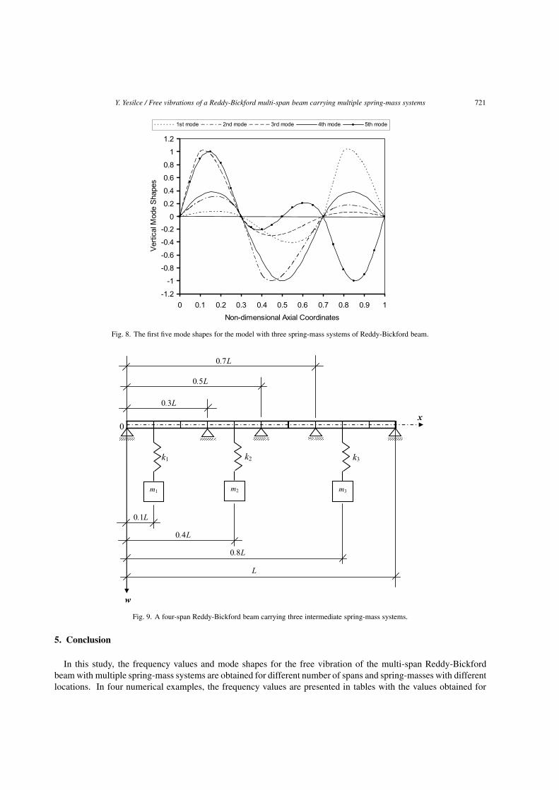
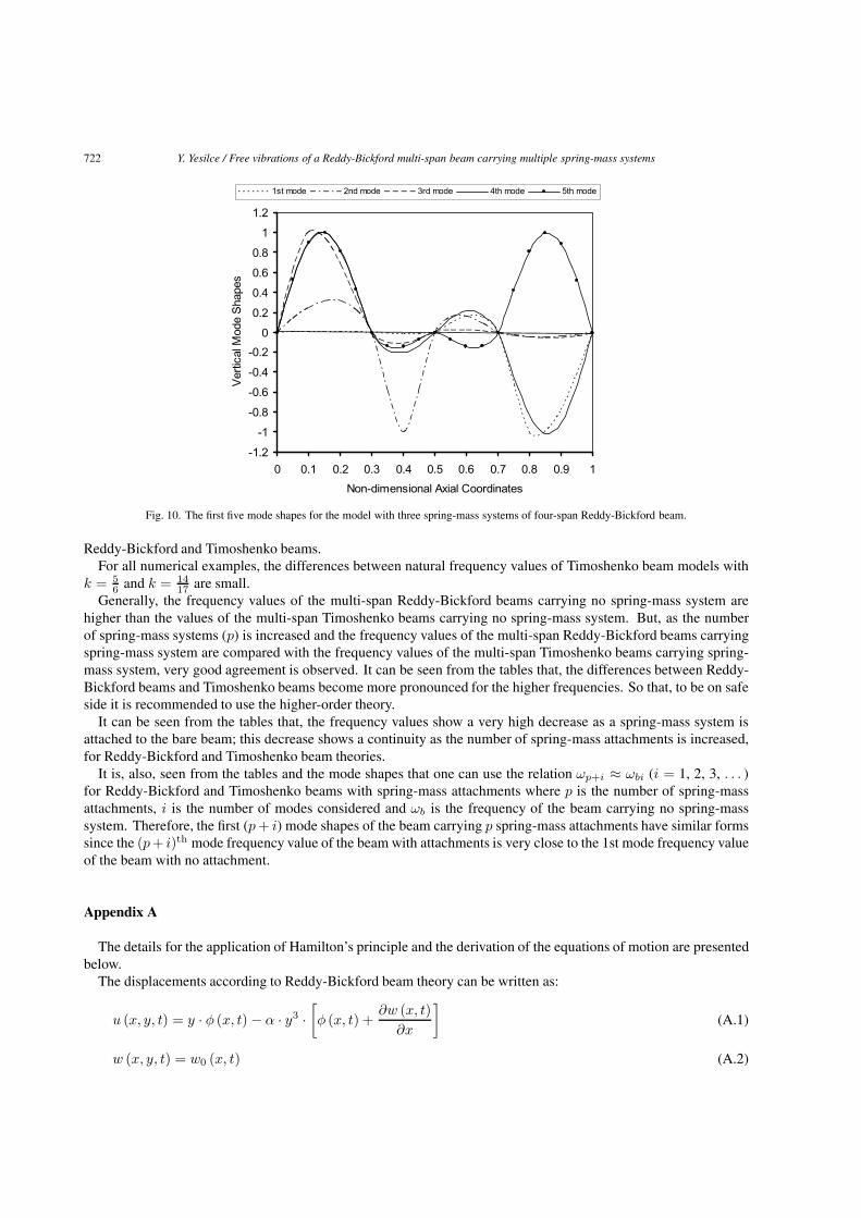
intermediate support, z2 = 0.5; for the third intermediate support z3 = 0.7; for the first, the second and the thirdintermediate spring-mass systems, locations and non-dimensional parameters are taken as which are given in Section3.3. The frequencyvalues obtained for the first five modes are presented in (Table 5) by comparingwith the frequencyvalues obtained for Timoshenko beam and mode shapes for the model with three spring-mass systems of four-spanReddy-Bickford beam are shown in (Fig. 10).
It is seen from (Table 5) that, as in Section 3.3, the 4th and 5th mode frequency values are very close to the 1stand 2nd modes frequency values obtained for the model with no attachment.
Y. Yesilce / Free vibrations of a Reddy-Bickford multi-span beam carrying multiple spring-mass systems 721
Fig. 8. The first five mode shapes for the model with three spring-mass systems of Reddy-Bickford beam.
Fig. 9. A four-span Reddy-Bickford beam carrying three intermediate spring-mass systems.
5. Conclusion
In this study, the frequency values and mode shapes for the free vibration of the multi-span Reddy-Bickfordbeam with multiple spring-mass systems are obtained for different number of spans and spring-masses with differentlocations. In four numerical examples, the frequency values are presented in tables with the values obtained for
722 Y. Yesilce / Free vibrations of a Reddy-Bickford multi-span beam carrying multiple spring-mass systems
Fig. 10. The first five mode shapes for the model with three spring-mass systems of four-span Reddy-Bickford beam.
Reddy-Bickford and Timoshenko beams.For all numerical examples, the differences between natural frequency values of Timoshenko beam models with
k = 56 and k = 14
17 are small.Generally, the frequency values of the multi-span Reddy-Bickford beams carrying no spring-mass system are
higher than the values of the multi-span Timoshenko beams carrying no spring-mass system. But, as the numberof spring-mass systems (p) is increased and the frequency values of the multi-span Reddy-Bickford beams carryingspring-mass system are compared with the frequency values of the multi-span Timoshenko beams carrying spring-mass system, very good agreement is observed. It can be seen from the tables that, the differences between Reddy-Bickford beams and Timoshenko beams become more pronounced for the higher frequencies. So that, to be on safeside it is recommended to use the higher-order theory.
It can be seen from the tables that, the frequency values show a very high decrease as a spring-mass system isattached to the bare beam; this decrease shows a continuity as the number of spring-mass attachments is increased,for Reddy-Bickford and Timoshenko beam theories.
It is, also, seen from the tables and the mode shapes that one can use the relation ωp+i ≈ ωbi (i = 1, 2, 3, . . . )for Reddy-Bickford and Timoshenko beams with spring-mass attachments where p is the number of spring-massattachments, i is the number of modes considered and ωb is the frequency of the beam carrying no spring-masssystem. Therefore, the first (p + i) mode shapes of the beam carrying p spring-mass attachments have similar formssince the (p+ i)th mode frequency value of the beam with attachments is very close to the 1st mode frequency valueof the beam with no attachment.
Appendix A
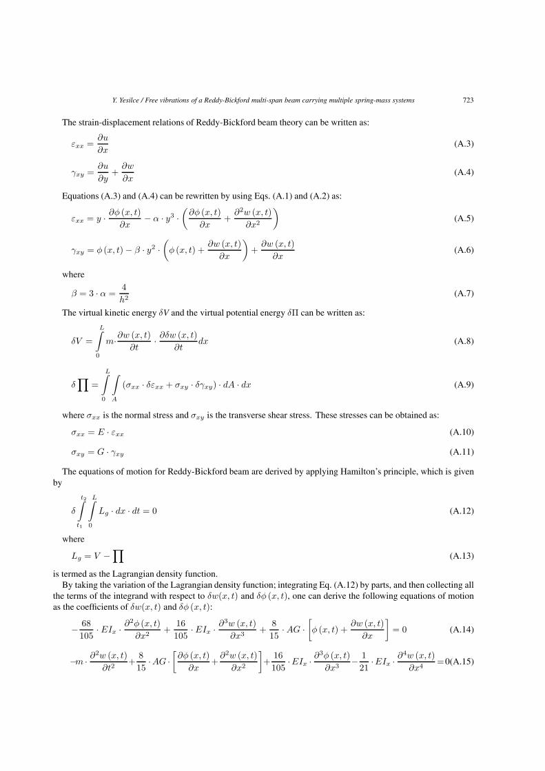
The details for the application of Hamilton’s principle and the derivation of the equations of motion are presentedbelow.
The displacements according to Reddy-Bickford beam theory can be written as:
u (x, y, t) = y · φ (x, t) − α · y3 ·[φ (x, t) +
∂w (x, t)∂x
](A.1)
w (x, y, t) = w0 (x, t) (A.2)
Y. Yesilce / Free vibrations of a Reddy-Bickford multi-span beam carrying multiple spring-mass systems 723
The strain-displacement relations of Reddy-Bickford beam theory can be written as:
εxx =∂u
∂x(A.3)
γxy =∂u
∂y+
∂w
∂x(A.4)
Equations (A.3) and (A.4) can be rewritten by using Eqs. (A.1) and (A.2) as:
εxx = y · ∂φ (x, t)∂x
− α · y3 ·(
∂φ (x, t)∂x
+∂2w (x, t)
∂x2
)(A.5)
γxy = φ (x, t) − β · y2 ·(
φ (x, t) +∂w (x, t)
∂x
)+
∂w (x, t)∂x
(A.6)
where
β = 3 · α =4h2
(A.7)
The virtual kinetic energy δV and the virtual potential energy δΠ can be written as:
δV =
L∫0
m·∂w (x, t)∂t
· ∂δw (x, t)∂t
dx (A.8)
δ∏
=
L∫0
∫A
(σxx · δεxx + σxy · δγxy) · dA · dx (A.9)
where σxx is the normal stress and σxy is the transverse shear stress. These stresses can be obtained as:
σxx = E · εxx (A.10)
σxy = G · γxy (A.11)
The equations of motion for Reddy-Bickford beam are derived by applying Hamilton’s principle, which is givenby
δ
t2∫t1
L∫0
Lg · dx · dt = 0 (A.12)
where
Lg = V −∏
(A.13)
is termed as the Lagrangian density function.By taking the variation of the Lagrangian density function; integrating Eq. (A.12) by parts, and then collecting all
the terms of the integrand with respect to δw(x, t) and δφ (x, t), one can derive the following equations of motionas the coefficients of δw(x, t) and δφ (x, t):
− 68105
· EIx · ∂2φ (x, t)∂x2
+16105
· EIx · ∂3w (x, t)∂x3
+815
· AG ·[φ (x, t) +
∂w (x, t)∂x
]= 0 (A.14)
−m · ∂2w (x, t)∂t2
+815
·AG ·[∂φ (x, t)
∂x+
∂2w (x, t)∂x2
]+
16105
·EIx · ∂3φ (x, t)∂x3
− 121
·EIx · ∂4w (x, t)∂x4
=0(A.15)
724 Y. Yesilce / Free vibrations of a Reddy-Bickford multi-span beam carrying multiple spring-mass systems
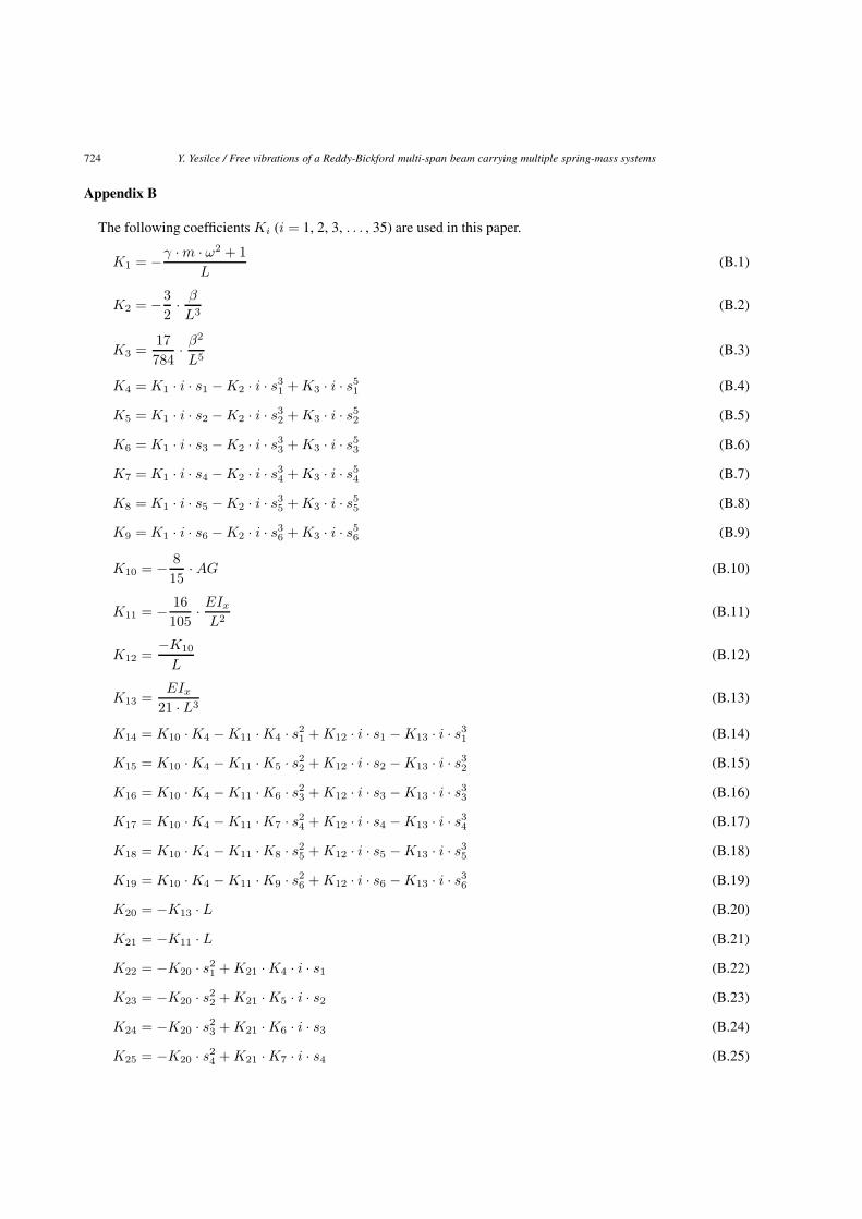
Appendix B
The following coefficients Ki (i = 1, 2, 3, . . . , 35) are used in this paper.
K1 = −γ · m · ω2 + 1L
(B.1)
K2 = −32· β
L3(B.2)
K3 =17784
· β2
L5(B.3)
K4 = K1 · i · s1 − K2 · i · s31 + K3 · i · s5
1 (B.4)
K5 = K1 · i · s2 − K2 · i · s32 + K3 · i · s5
2 (B.5)
K6 = K1 · i · s3 − K2 · i · s33 + K3 · i · s5
3 (B.6)
K7 = K1 · i · s4 − K2 · i · s34 + K3 · i · s5
4 (B.7)
K8 = K1 · i · s5 − K2 · i · s35 + K3 · i · s5
5 (B.8)
K9 = K1 · i · s6 − K2 · i · s36 + K3 · i · s5
6 (B.9)
K10 = − 815
· AG (B.10)
K11 = − 16105
· EIx
L2(B.11)
K12 =−K10
L(B.12)
K13 =EIx
21 · L3(B.13)
K14 = K10 · K4 − K11 · K4 · s21 + K12 · i · s1 − K13 · i · s3
1 (B.14)
K15 = K10 · K4 − K11 · K5 · s22 + K12 · i · s2 − K13 · i · s3
2 (B.15)
K16 = K10 · K4 − K11 · K6 · s23 + K12 · i · s3 − K13 · i · s3
3 (B.16)
K17 = K10 · K4 − K11 · K7 · s24 + K12 · i · s4 − K13 · i · s3
4 (B.17)
K18 = K10 · K4 − K11 · K8 · s25 + K12 · i · s5 − K13 · i · s3
5 (B.18)
K19 = K10 · K4 − K11 · K9 · s26 + K12 · i · s6 − K13 · i · s3
6 (B.19)
K20 = −K13 · L (B.20)
K21 = −K11 · L (B.21)
K22 = −K20 · s21 + K21 · K4 · i · s1 (B.22)
K23 = −K20 · s22 + K21 · K5 · i · s2 (B.23)
K24 = −K20 · s23 + K21 · K6 · i · s3 (B.24)
K25 = −K20 · s24 + K21 · K7 · i · s4 (B.25)
Y. Yesilce / Free vibrations of a Reddy-Bickford multi-span beam carrying multiple spring-mass systems 725
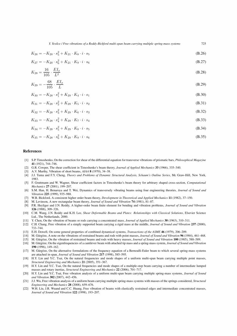
K26 = −K20 · s25 + K21 · K8 · i · s5 (B.26)
K27 = −K20 · s26 + K21 · K9 · i · s6 (B.27)
K28 =16105
· EIx
L2(B.28)
K29 = − 68105
· EIx
L(B.29)
K30 = −K28 · s21 + K29 · K4 · i · s1 (B.30)
K31 = −K28 · s22 + K29 · K5 · i · s2 (B.31)
K32 = −K28 · s23 + K29 · K6 · i · s3 (B.32)
K33 = −K28 · s24 + K29 · K7 · i · s4 (B.33)
K34 = −K28 · s25 + K29 · K8 · i · s5 (B.34)
K35 = −K28 · s26 + K29 · K9 · i · s6 (B.35)
References
[1] S.P. Timoshenko, On the correction for shear of the differential equation for transverse vibrations of prismatic bars, Philosophical Magazine41 (1921), 744–746.
[2] G.R. Cowper, The shear coefficient in Timoshenko’s beam theory, Journal of Applied Mechanics 33 (1966), 335–340.[3] A.V. Murthy, Vibration of short beams, AIAA 8 (1970), 34–38.[4] J.J. Tuma and F.Y. Cheng, Theory and Problems of Dynamic Structural Analysis, Schaum’s Outline Series, Mc Graw-Hill, New York,
1983.[5] F. Gruttmann and W. Wagner, Shear coefficient factors in Timoshenko’s beam theory for arbitrary shaped cross-section, Computational
Mechanics 27 (2001), 199–207.[6] S.M. Han, H. Benaroya and T. Wei, Dynamics of transversely vibrating beams using four engineering theories, Journal of Sound and
Vibration 225 (1999), 935–988.[7] W.B. Bickford, A consistent higher order beam theory, Development in Theoretical and Applied Mechanics 11 (1982), 37–150.[8] M. Levinson, A new rectangular beam theory, Journal of Sound and Vibration 74 (1981), 81–87.[9] P.R. Heyliger and J.N. Reddy, A higher-order beam finite element for bending and vibration problems, Journal of Sound and Vibration
126 (1988), 309–326.[10] C.M. Wang, J.N. Reddy and K.H. Lee, Shear Deformable Beams and Plates: Relationships with Classical Solutions, Elsevier Science
Ltd., The Netherlands, 2000.[11] Y. Chen, On the vibration of beams or rods carrying a concentrated mass, Journal of Applied Mechanics 30 (1963), 310–311.[12] C.H. Chang, Free vibration of a simply supported beam carrying a rigid mass at the middle, Journal of Sound and Vibration 237 (2000),
733–744.[13] E.H. Dowell, On some general properties of combined dynamical systems, Transactions of the ASME 46 (1979), 206–209.[14] M. Gurgoze, A note on the vibrations of restrained beams and rods with point masses, Journal of Sound and Vibration 96 (1984), 461–468.[15] M. Gurgoze, On the vibration of restrained beams and rods with heavy masses, Journal of Sound and Vibration 100 (1985), 588–589.[16] M. Gurgoze, On the eigenfrequencies of a cantilever beam with attached tip mass and a spring-mass system, Journal of Sound and Vibration
190 (1996), 149–162.[17] M. Gurgoze, On the alternative formulations of the frequency equation of a Bernoulli-Euler beam to which several spring-mass systems
are attached in-span, Journal of Sound and Vibration 217 (1998), 585–595.[18] H.Y. Lin and Y.C. Tsai, On the natural frequencies and mode shapes of a uniform multi-span beam carrying multiple point masses,
Structural Engineering and Mechanics 21 (2005), 351–367.[19] H.Y. Lin and Y.C. Tsai, On the natural frequencies and mode shapes of a multiple-step beam carrying a number of intermediate lumped
masses and rotary inertias, Structural Engineering and Mechanics 22 (2006), 701–717.[20] H.Y. Lin and Y.C. Tsai, Free vibration analysis of a uniform multi-span beam carrying multiple spring-mass systems, Journal of Sound
and Vibration 302 (2007), 442–456.[21] J.J. Wu, Free vibration analysis of a uniform beam carrying multiple spring-mass systems with masses of the springs considered, Structural
Engineering and Mechanics 28 (2008), 659–676.[22] W.H. Liu, J.R. Wuand and C.C. Huang, Free vibration of beams with elastically restrained edges and intermediate concentrated masses,
Journal of Sound and Vibration 122 (1998), 193–207.
726 Y. Yesilce / Free vibrations of a Reddy-Bickford multi-span beam carrying multiple spring-mass systems
[23] J.S. Wu and H.M. Chou, A new approach for determining the natural frequencies and mode shape of a uniform beam carrying any numberof spring masses, Journal of Sound and Vibration 220 (1999), 451–468.
[24] S. Naguleswaran, Transverse vibrations of an Euler-Bernoulli uniform beam carrying several particles, International Journal of MechanicalScience 44 (2002), 2463–2478.
[25] S. Naguleswaran, Transverse vibration of an Euler-Bernoulli uniform beam on up o five resilient supports including ends, Journal of Soundand Vibration 261 (2003), 372–384.
[26] D. Zhou, Free vibration of multi-span Timoshenko beams using static Timoshenko beam functions, Journal of Sound and Vibration 241(2001), 725–734.
[27] J.S. Wu and D.W. Chen, Free vibration analysis of a Timoshenko beam carrying multiple spring-mass systems by using the numericalassembly technique, International Journal of Numerical Methods in Engineering 50 (2001), 1039–1058.
[28] H.P. Lin and S.C. Chang, Free vibration analysis of multi-span beams with intermediate flexible constraints, Journal of Sound and Vibration281 (2005), 155–169.
[29] J.R. Wang, T.L. Liu and D.W. Chen, Free vibration analysis of a Timoshenko beam carrying multiple spring-mass systems with the effectsof shear deformation and rotary inertia, Structural Engineering and Mechanics 26 (2007), 1–14.
[30] Y. Yesilce and O. Demirdag, Effect of axial force on free vibration of Timoshenko multi-span beam carrying multiple spring-mass systems,International Journal of Mechanical Science 50 (2008), 995–1003.
[31] S. Kukla and B. Posiadala, Free vibrations of beams with elastically mounted masses, Journal of Sound and Vibration 175 (1994), 557–564.[32] H. Su and J.R. Banerjee, Exact natural frequencies of structures consisting of two part beam-mass systems, Structural Engineering and
Mechanics 19 (2005), 551–566.

International Journal of
AerospaceEngineeringHindawi Publishing Corporationhttp://www.hindawi.com Volume 2010
RoboticsJournal of
Hindawi Publishing Corporationhttp://www.hindawi.com Volume 2014
Hindawi Publishing Corporationhttp://www.hindawi.com Volume 2014
Active and Passive Electronic Components
Control Scienceand Engineering
Journal of
Hindawi Publishing Corporationhttp://www.hindawi.com Volume 2014
International Journal of
RotatingMachinery
Hindawi Publishing Corporationhttp://www.hindawi.com Volume 2014
Hindawi Publishing Corporation http://www.hindawi.com
Journal ofEngineeringVolume 2014
Submit your manuscripts athttp://www.hindawi.com
VLSI Design
Hindawi Publishing Corporationhttp://www.hindawi.com Volume 2014
Hindawi Publishing Corporationhttp://www.hindawi.com Volume 2014
Shock and Vibration
Hindawi Publishing Corporationhttp://www.hindawi.com Volume 2014
Civil EngineeringAdvances in
Acoustics and VibrationAdvances in
Hindawi Publishing Corporationhttp://www.hindawi.com Volume 2014
Hindawi Publishing Corporationhttp://www.hindawi.com Volume 2014
Electrical and Computer Engineering
Journal of
Advances inOptoElectronics
Hindawi Publishing Corporation http://www.hindawi.com
Volume 2014
The Scientific World JournalHindawi Publishing Corporation http://www.hindawi.com Volume 2014
SensorsJournal of
Hindawi Publishing Corporationhttp://www.hindawi.com Volume 2014
Modelling & Simulation in EngineeringHindawi Publishing Corporation http://www.hindawi.com Volume 2014
Hindawi Publishing Corporationhttp://www.hindawi.com Volume 2014
Chemical EngineeringInternational Journal of Antennas and
Propagation
International Journal of
Hindawi Publishing Corporationhttp://www.hindawi.com Volume 2014
Hindawi Publishing Corporationhttp://www.hindawi.com Volume 2014
Navigation and Observation
International Journal of
Hindawi Publishing Corporationhttp://www.hindawi.com Volume 2014
DistributedSensor Networks
International Journal of