Embed Size (px)
Citation preview

Free Vibration and Buckling Behaviour of Laminated
Composite Panel under Thermal and Mechanical Loading
Katariya Pankajkumar Vaikunthbhai
Free Vibration and Buckling Behaviour of Laminated
Composite Panel under Thermal and Mechanical Loading
Thesis Submitted in Partial Fulfillment
of the Requirements for the award of the Degree
of
Master of Technology (Research)
by
Katariya Pankajkumar Vaikunthbhai
Roll No. 611ME311
Under the Supervision of
Prof. Subrata Kumar Panda
Department of Mechanical Engineering
National Institute of Technology Rourkela
Odisha (India) -769 008
January 2014
Dedicated
To
My Parents
&
Jayesh V. Katariya
Meeta J. Katariya
CERTIFICATE OF APPROVAL
Certified that the thesis entitled “Free Vibration and Buckling Behaviour of Laminated
Composite Panel under Thermal and Mechanical Loading” submitted by Katariya
Pankajkumar Vaikunthbhai National Institute of Technology, Rourkela, for award of the
degree of Master of Technology (Research) has been accepted by the external examiners and
that the student has successfully defended the thesis in the viva-voce examination held today.
Signature:
Name: Prof. H. P. Roy
(Member of the MSC)
Signature:
Name: Prof. R. K. Behera
(Member of the MSC)
Signature:
Name: Prof. A. V. Asha
(Member of the MSC)
Signature:
Name: Prof. S. K. Panda
(Supervisor)
Signature:
Name: Prof. S. S. Mahapatra
(Chairmen)
Signature:
Name: Prof. S. K. Panigrahi
(External Examiner)
Declaration
I certify that
a. The work contained in the thesis is original and has been done by myself under the
general supervision of my supervisor.
b. The work has not been submitted to any other Institute for any degree or diploma.
c. I have followed the guidelines provided by the Institute in writing the thesis.
d. I have conformed to the norms and guidelines given in the Ethical Code of Conduct
of the Institute.
e. Whenever I have used material (data, theoretical analysis and text) from other sources,
I have given due credit to them by citing them in the text of the thesis and giving their
details in the references.
f. Whenever I have quoted written materials from other source, I have put them under
quotation marks and given due credit to the sources by citing them and giving required
details in the references.
(Katariya Pankajkumar Vaikunthbhai)

NATIONAL INSTITUE OF TECHNOLOGY
ROURKELA -769 008, ODISHA, INDIA
DEPARTMENT OF MECHANICAL ENGINEERING
Certificate
This is to certify that the thesis entitled, “Free Vibration and Buckling behaviour of
Laminated Composite Panels under Thermal and Mechanical Loading”, being submitted
by Mr. Katariya Pankajkumar Vaikunthbhai to the Department of Mechanical Engineering,
National Institute of Technology, Rourkela, for the partial fulfillment of award of the degree
Master of Technology (Research), is an authentic research work carried out by him under my
supervision and guidance. This thesis in my opinion, is worthy of consideration for award of
the degree of Master of Technology (Research) in accordance with the regulation of the
institute. To the best of my knowledge, the matter embodied in this thesis has not been
submitted to any other university/ institute for award of any Degree or Diploma.
Thesis Supervisor
(Dr. Subrata Kumar Panda)
Assistant Professor,
Department of Mechanical Engineering
National Institute of Technology
Rourkela, Odisha, India- 769 008
VI
Acknowledgement
My first thanks are to the Almighty God, without whose blessings, I wouldn't have been
writing this “acknowledgments".
It is with a feeling of great pleasure that I would like to express my most sincere heartfelt
gratitude to Prof. Subrata Kumar Panda, Assistant Professor, Dept. of Mechanical
Engineering, NIT, Rourkela for suggesting the topic for my thesis report and for his ready
and able guidance throughout the course of my preparing the report. I am especially obliged
to him for teaching me both research and writing skills, which have been proven beneficial
for my current research and future career. I thank you Sir, for your help, inspiration and
blessings.
I express my sincere thanks to Prof. S. K. Sarangi, Professor and Director, NIT, Rourkela,
Prof. K. P. Maity, Professor and HOD, Dept. of Mechanical Engineering NIT, Rourkela for
providing me the necessary facilities in the department.
Submitting this thesis would have been a Herculean job, without the constant help,
encouragement, support and suggestions from my friends, especially Vishesh R. Kar, Vijay
K. Singh, Girish K. Sahu, Pradeep K. Mishra, Rohit Singh and Abdul Hussain, for their
time to help. It will be difficult to record my appreciation to each and every one of them in
this small space. I will relish your memories for years to come.
I must like to thank my parents and other family members, for their support for choices in
all my life and their love, which has been a constant source of strength for everything I do.
Katariya Pankajkumar Vaikunthbhai
Roll No. 611ME311
VII
Abstract
Laminated composites have been used in various industries such as aerospace,
mechanical, chemical, space craft and other high performance engineering applications. This
in turn created the requirement of analysis of these structures/structural components through
mathematical, experimental and/or simulation based model for accurate design and
subsequent manufacturing. These structures are exposed to large acoustic, vibration, inertia
excitation as well as unlike environmental condition during their service life. The elevated
thermal loading often changes the original geometry of the panel due to excess deformation
and the final structural performance affected greatly. The first mode of vibration/fundamental
frequency is always associated with high amplitude and it causes large tension and/or
compression which leads to fatigue of the structural component. Therefore, the vibration
analysis of laminated structures made-up of composite and/or hybrid materials becomes
significant. In general, buckling is the state of geometrical instability of the structure induced
by the in-plane thermal/mechanical/thermo-mechanical forces. It is important to mention that,
the geometric strain associated with buckling is always nonlinear in nature. In this study a
general mathematical model is developed for laminated composite single/doubly curved
(cylindrical/ spherical/ hyperboloid/ elliptical) panel in the framework of higher order shear
deformation theory. The geometrical distortion of the laminated panels due to in-plane
(thermal/mechanical/thermo-mechanical) load have been incorporated through Green-
Lagrange nonlinearity to count the exact flexure. The developed mathematical model has
been discretised using suitable finite element steps to obtain the sets of algebraic equations
for the domain. The equations are solved through a computer code developed in MATLAB
environment to obtain the desired solutions. In addition to this, a simulation model have been
developed in ANSYS for all different cases and the responses are checked to show the
generality of the present developed model. The effects of thickness ratio, aspect ratio,
curvature ratio, modular ratio, stacking sequence, number of layer and support condition and
the material properties on the vibration and the buckling responses are studied in detail.
Keywords: Laminated panel, HSDT, Green-Lagrange nonlinearity, FEM, vibration,
thermal/mechanical buckling, ANSYS, APDL code
VIII
Bio-Data
Name: Katariya Pankajkumar Vaikunthbhai
Date of Birth: 24.05.1990
Educational Qualification:
Examination Name of the
Institute Board/University
Year of
passing Division Subject
S.S.C. Shree
Swaminarayan
Vidhyalay,
Vapi
G.S.H.E.B. 2005 Distinction All
H.S.C. Shri Saraswat
Vidhyalay,
Vapi
G.S.H.E.B. 2007 1st Science
B.E. SVIT Vasad,
Gujarat
Gujarat
University
2011 1st Aeronautical
Engineering
M.Tech
(Research)
N.I.T,
Rourkela
N.I.T, Rourkela Pursuing - Mechanical
Engineering
Permanent Add: c/o V. R. Katariya, Room No. 202/Khodiyar Krupa Soc.,
Chanod Colony, Silvassa Road, Vapi, Dist.- Valsad, Gujarat.
Mobile No. +91-9638597779
E-mail ID: [email protected]
IX
Contents
Title Page (I)
Certificate of Approval (III)
Declaration (IV)
Certificate by the Supervisor (V)
Acknowledgement (VI)
Abstract (VII)
Bio-Data (VIII)
Contents (IX)
List of Symbols (XII)
List of Tables (XV)
List of Figures (XVI)
Chapter 1 Introduction (1-13)
1.1 Overview (1)
1.2 Literature Review (3)
1.3 Vibration Analysis of Laminated Composite Panels (5)
1.4 Buckling Analysis of Laminated Composite Panels (6)
1.5 Introduction of Finite Element Method and ANSYS (9)
1.6 Motivation of the Present Work (10)
1.7 Objectives and Scope of the Present Thesis (11)
1.8 Organisation of the Thesis (12)
Chapter 2 General Mathematical Formulation (14-24)
2.1 Introduction (14)
2.2 Assumptions (15)
2.3 Displacement Field and Geometry of the Shell (15)
2.4 Strain-Displacement Relation (16)
2.5 Constitutive Relation (18)
X
2.6 Energy Calculation (19)
2.7 Finite Element Formulation (20)
2.8 Governing Equation (21)
2.9 Solution Technique (21)
2.10 Support Conditions (22)
2.11 Computational Investigations (23)
2.12 Summary (23)
Chapter 3 Free Vibration Analysis of Laminated Composite Shell Panels (25-40)
3.1 Introduction (25)
3.2 Governing Equation and Solution (25)
3.3 Results and Discussions (26)
3.4 Convergence and Validation Study of Vibration (26)
3.5 Numerical Examples (30)
3.5.1 Free Vibration Analysis using HSDT Model (31)
3.5.2 Free Vibration Analysis using ANSYS Model (35)
3.6 Conclusions (40)
Chapter 4 Buckling Analysis of Laminated Composite Shell Panels (41-59)
4.1 Introduction (41)
4.2 Governing Equation and Solution (41)
4.3 Results and Discussions (42)
4.4 Convergence and validation study of buckling (42)
4.5 Numerical Examples (45)
4.5.1 Thermal Buckling Analysis using HSDT Model (46)
4.5.2 Thermal Buckling Analysis using ANSYS Model (49)
4.5.3 Mechanical Buckling Analysis using HSDT Model (53)
4.5.4 Mechanical Buckling Analysis using ANSYS Model (54)
4.5.5 Thermo-Mechanical Buckling Analysis using HSDT Model (57)
4.6 Conclusions (58)
Chapter 5 Closure (60-63)
5.1 Concluding Remarks (60)
5.2 Significant Contribution of the Thesis (61)

XI
5.3 Future Scope of the Research (62)
References (64-70)
Appendix (71-75)
About the Author (76-77)
XII
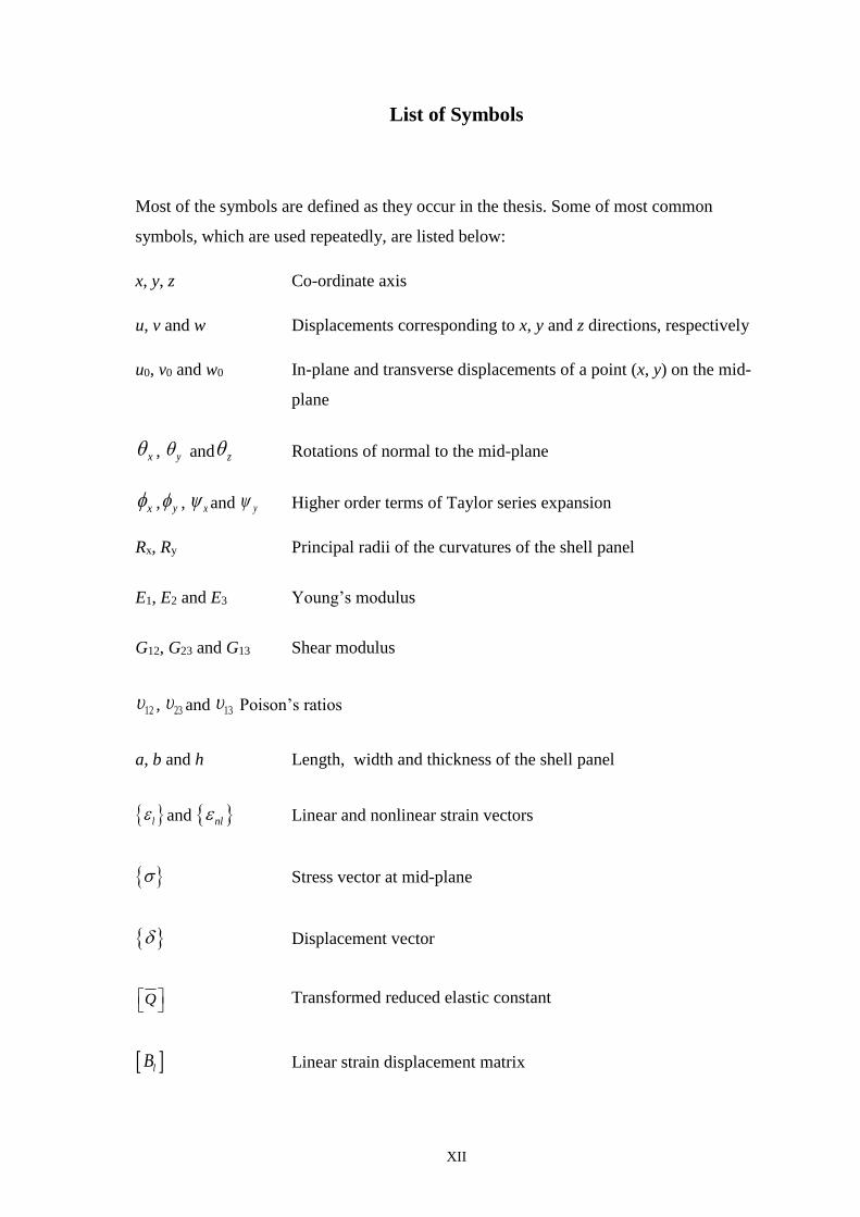
List of Symbols
Most of the symbols are defined as they occur in the thesis. Some of most common
symbols, which are used repeatedly, are listed below:
x, y, z Co-ordinate axis
u, v and w Displacements corresponding to x, y and z directions, respectively
u0, v0 and w0 In-plane and transverse displacements of a point (x, y) on the mid-
plane
x , y and z Rotations of normal to the mid-plane
x , y , x and y Higher order terms of Taylor series expansion
Rx, Ry Principal radii of the curvatures of the shell panel
E1, E2 and E3 Young’s modulus
G12, G23 and G13 Shear modulus
12 , 23 and 13 Poison’s ratios
a, b and h Length, width and thickness of the shell panel
l and nl Linear and nonlinear strain vectors
Stress vector at mid-plane
Displacement vector
Q
Transformed reduced elastic constant
lB Linear strain displacement matrix
XIII
D Rigidity matrix
SK Linear stiffness matrix
GK Geometric stiffness matrix
M Mass matrix
F Global force vector
US.E. Strain energy
T Function of thickness co-ordinate
Thermal expansion co-efficient
Density of the material
T Kinetic energy
W Work done
a/h Thickness ratio
R/a Curvature ratio
E1/E2 Modular ratio
Non-dimensional fundamental frequency
cr Non-dimensional buckling temperature
NX Non-dimensional buckling load
XIV
Subscript
l Linear
nl Nonlinear
S Symmetric
i Node number
Abbreviation
CLPT Classical laminate plate theory
FSDT First order shear deformation theory
HSDT Higher order shear deformation theory
APDL ANSYS parametric design language
SSSS All edges simply supported
CCCC All edges clamped
CFFF One edge clamped and all other edges free
SCSC Two parallel edges simply supported and other two edges clamped
CSCS Two parallel edges clamped and other two edges simply supported
SSCC Two perpendicular edges simply supported and other two edges
clamped
CCSS Two perpendicular edges clamped and other two edges simply
supported
Eq. Equation
GPa Giga Pascal
DOFs Degrees of freedom
XV
List of Tables
Table No. Page
No.
3.1 Material properties of the laminated composite structures (26)
4.1 Comparison of non-dimensional buckling temperature of
simply supported angle-ply laminated flat
(44)
4.2 Comparison of non-dimensional buckling load of square simply
supported cross-ply laminated composite flat panel
(45)
4.3 Variation of buckling temperature parameter of cross-ply
(00/900)3 and angle-ply (±150)3 laminated composite cylindrical
panel
(47)
4.4 Non-dimensional buckling temperature of clamped square
angle-ply (±450)5 laminated cylindrical shell panel
(48)
4.5 Critical buckling temperature responses of cross-ply (00/900)5
laminated composite spherical, hyperboloid and elliptical panel
for different support condition
(48)
4.6 Critical buckling load of clamped cross-ply (00/900)5 laminated
shell under bi-axial loading (E1/E2=40, R/a=10 and
2 3
2/x xxN N a E h )
(53)
4.7 Critical buckling load of simply supported angle-ply (±450)5
laminated shell under uniaxial loading (E1/E2=25, R/a=20 and
2/ ( )X XXN N E h )
(53)
XVI
List of Figures
Figure No. Page No.
1.1 Figure 1.1 Deformation of a transverse normal according to the
classical, first-order, and third-order plate theories
(4)
1.2 SHELL281 Geometry [75] (9)
2.1 Laminated composite doubly curved shell geometry (16)
2.2 Representation of the solutions steps (22)
3.1 Convergence and comparison study of simply supported
laminated composite cylindrical panel (R/a=10 and a/h=10)
(27)
3.2 Convergence and comparison study of simply supported cross-
ply (00/900/900/00) laminated composite flat panel (a/h=5)
(27)
3.3 Convergence study of laminated composite cylindrical panel of
different lamination schemes for all edges clamped support
condition (a/h=10 and R/a=100)
(28)
3.4 Convergence study of laminated composite flat panel of
different lamination schemes and thickness ratios for one edge
clamped and other edges free support condition
(29)
3.5 Convergence study of simply supported laminated composite
spherical shell panel (E1/E2=25 and R/a=10)
(30)
3.6 Non-dimensional fundamental frequency responses of clamped
laminated composite flat panel
(31)
3.7 Non-dimensional fundamental frequency responses of CFFF
laminated composite flat panel
(32)
3.8 Non-dimensional fundamental frequency responses of clamped
laminated composite cylindrical panel
(32)
3.9 Non-dimensional fundamental frequency responses of angle-
ply (±450)5laminated composite spherical panel for different
support condition
(33)
3.10 Non-dimensional fundamental frequency responses of angle-
ply (±450)5 laminated composite elliptical panel for different
support condition
(34)
XVII
3.11 Non-dimensional fundamental frequency responses of angle-
ply (±450)5 laminated composite hyperboloid panel for different
support condition
(34)
XVIII
3.12 Non-dimensional fundamental frequency of cross-ply (00/900)2
laminated composite cylindrical panel
(35)
3.13 Non-dimensional fundamental frequency of angle-ply (±300)2
laminated composite cylindrical panel
(36)
3.14 Non-dimensional fundamental frequency responses of simply
supported laminated composite spherical shell panel (R/a=10)
(37)
3.15 Non-dimensional fundamental frequency responses of cross-ply
(00/900)S laminated composite spherical shell panel (a/b=1)
(37)
3.16 Non-dimensional fundamental frequency responses of angle-
ply (±45)S laminated composite spherical shell panel (a/b=1)
(38)
3.17 Non-dimensional fundamental frequency of cross-ply (00/900)2
laminated composite flat panel
(38)
3.18 Non-dimensional fundamental frequency of clamped laminated
composite flat panel
(39)
3.19 Non-dimensional fundamental frequency of CSCS laminated
composite flat panel
(40)
4.1 Convergence study of non-dimensional buckling temperature of
simply supported angle-ply (±450)3 laminated composite flat
panel
(43)
4.2 Convergence study of non-dimensional buckling load of simply
supported laminated composite cylindrical shell panel (R/a = 2
and a/h=5)
(45)
4.3 Variation of buckling temperature parameter of cross-ply and
angle-ply laminated composite flat panel
(46)
4.4 Non-dimensional buckling temperature for (00/900)2 flat panel
for different support condition
(49)
4.5 Non-dimensional buckling temperature for (±450)2 flat panel
for different support conditions
(50)
XIX
4.6 Non-dimensional buckling temperature of CCCC laminated
composite flat panel
(51)
4.7 No Non-dimensional buckling temperature of CSCS laminated
composite flat panel
(51)
4.8 Mode shape of simply supported cross-ply (00/900)5 laminated
composite flat panel
(52)
4.9 Mode shape of clamped cross-ply (00/900)5 laminated
composite flat panel
(52)
4.10 Non-dimensional buckling load of laminated composite flat
panel for CCSS condition under bi-axial loading
(54)
4.11 Non-dimensional buckling load of laminated composite flat
panel for CCSS condition under uniaxial loading
(55)
4.12 Non-dimensional buckling load of cross-ply (00/900)2 laminated
composite cylindrical panel for different support condition
under uniaxial loading
(56)
4.13 Non-dimensional buckling load of angle-ply (±450)2 laminated
composite cylindrical panel for different support condition
under uniaxial loading
(56)
4.14 Non-dimensional critical buckling temperature of clamped
square laminated composite cylindrical panel (R/a=10)
(57)
4.15 Non-dimensional critical buckling temperature of clamped
square laminated composite spherical panel (R/a=10)
(58)
Chapter 1 Introduction
1
CHAPTER 1
INTRODUCTION
1.1 Overview
Nowadays laminated composite shells are used in many structural parts of various
modern vehicles, buildings, historical and engineering structures. A shell panel can be defined
as curved thin/thick surface. It may be made from a single layer or multilayer of isotropic or
anisotropic materials. The shell panel can be classified according to the curvatures such as
doubly curved (both principal curvatures are unequal), cylindrical (one of the principal
curvature is zero), spherical (both principal curvatures are equal), conical (where one of the
curvatures is zero and the other changes linearly with the axial length), and flat panel (both
curvatures are zero). Laminated composites are incredibly lightweight, especially in
comparison to traditional materials like concrete, metal, and wood. Composite materials are
extremely strong especially per unit of volume/weight, low co-efficient of thermal expansion,
excellent elastic properties and good corrosion resistant and highly resistant to chemicals. The
composites have ability to allow the structural properties to be tailored according to
requirements which add to their versatility for high performance engineering applications. A
sufficient amount of weight can be dropped by using composites as compared to conventional
materials, viz. the new Boeing 787 (Dreamliner), has used 50 percent composite materials
dropping its overall weight by 12% (approx.) and added strength and lower weight allow the
plane to use less fuel [76]. In order to meet the economic challenges present days it is
necessary to manufacture the composite structures on the large scale as it effect on the cost
and availability of the composite structure. It is necessary to analyse these components
through mathematical and/or simulation based model beforehand for design and
manufacturing. The external skins of aircraft/spacecraft/automobile are having panel type of
geometry and made of the thin laminated composites. As discussed the structural components
of high speed aircrafts, rockets and launch vehicles are subjected to intense loading due to the
aerodynamic heating during their service as a result the structural responses such as
deformations, buckling and natural frequencies are affected considerably.
The shell panel has significantly higher membrane stiffness than that of the bending
stiffness due to which it is capable to absorb a large value of membrane strain energy without
Chapter 1 Introduction
2
excessive deformations. If the shell is loaded in such a way that most of its strain energy is in
the form of membrane compression, and if there is a way that this stored-up membrane energy
can be converted into bending energy, the shell may fail dramatically in a process called
“buckling”. Hence, the buckling plays an important role in the design and analysis of the
structures. Basically two types of buckling occur in structural member namely, eigenvalue/
bifurcation buckling and non-linear/ limit point buckling [74]. The bifurcation buckling is a
form instability in which there is a sudden change of shape of the structure due to the axial
compressive/tensile load. However, in the limit point buckling there is no sudden change of
shape but it deviates from the primary equilibrium path after reaching the critical load i.e.,
known as “snap through”. It is well known that buckling doesn’t mean the failure of the
structural components and they are still capable to carry extra amount of load beyond the
buckling point without failure.
Today most of the engineering structural components firstly replaced with laminated
composite curved/flat panels due to their tailor made properties. The panel structures are
known for their high energy absorbing capability. It is also, true that the original geometry of
the panel is distorted because of the excess deformation due to induced in-plane
thermal/mechanical stress. This in turn affects the stiffness properties of the panel structure.
The vibrations with high amplitude cause great tensions and the reduction of life due to
fatigue. It is well known that, thin laminated structures are prone to buckle as well as the
structural geometry affects the final performances under combined loading.
It is important to mention that, the geometric strain associated with the buckling
phenomena is nonlinear in nature. Many researchers have already reported the buckling
responses of the laminated structures by taking the geometric nonlinearity in von-Karman
sense based on the various classical and shear deformation theories. Hence, to predict the
buckling strength of laminated shell panel structures, the mathematical model has to be
sufficient enough to incorporate the geometric alteration due to the excess deformation under
in-plane loading. The Green-Lagrange type nonlinear kinematics is taken instead of von-
Karman type for the actual prediction for a realistic model development to analyse the
buckling of laminated structures. However, the studies related to buckling by taking the
geometric nonlinearity in Green-Lagrange sense in conjunction with higher order mid-plane
kinematics are very few. Hence there is a need to investigate the buckling of the shell panels
taking the nonlinearity in Green-Lagrange sense based on the higher order shear deformation
theory for more accurate prediction of the responses of the structure. Therefore the stability
Chapter 1 Introduction
3
and vibration analysis of laminated structures made-up of composite materials becomes
significant.
To understand the realistic nature of the structural responses of vibration and buckling
(thermal/mechanical/thermo-mechanical) of laminated composite curved/flat panel, the
mathematical model is proposed to be developed based on a higher order shear deformation
theory (HSDT). It is important to mention that the strain displacement relation is considered
in Green-Lagrange type to take into account the geometrical nonlinearity arising in the curved
panel due to excess thermal and/or mechanical deformation for evaluation of geometric
stiffness matrix in buckling case. It is worthy to mention that the structural components made
up of laminated composite has created the necessity to model and analyse, it is because of the
fact that these problems are not only interesting but also challenging in many front. Hence,
the actual predictions of the fundamental frequency and critical buckling load/temperature
parameters are necessary to examined and to achieve the same, modelling of these structures
is one of the major aspects from a designer’s point of view. Parametric study gives the idea
regarding effect of geometries, material properties, types of loading of laminated structure
and their limiting conditions. In order to introduce the present problem some of the earlier
work completed by other researcher have been discussed in the forthcoming section.
1.2 Literature Review
The vibration and buckling (thermal/mechanical/thermo-mechanical) behaviour of
laminated composite panels are studied by many researchers to fill the gap by using numerical
and analytical methods. From last few decades, laminated composite panels are modelled
based on various theories to capture the true flexure of the structures under the influence
various types of combined loading. The analysis of plate and shell structures are mainly based
on the three theories:
The classical laminate plate theory (CLPT)
The first-order shear deformation theory (FSDT)
The higher order shear deformation theory (HSDT)
The classical laminate plate theory and the first-order shear deformation theories have
been used by many researcher in past due to their many advantages and these theories are also
encounter with one major lacuna like shear correction factor when analysing for thin
laminated structure. Hence, to overcome from the lacuna of above discussed theories higher
order theories have been developed to model the mid-plane kinematic deformation correctly.
Chapter 1 Introduction
4
However, the stress resultant involved in that are difficult to interpret physically and need
much more computational effort. In first order shear deformation theory and higher order
shear deformation theory the effect of transverse shear deformation may be essential in some
cases, whereas it is neglected in classical laminate plate theory due to the Kirchhoff
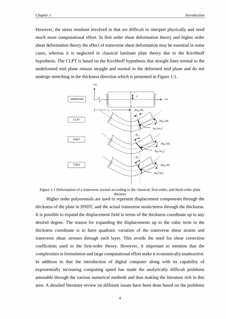
hypothesis. The CLPT is based on the Kirchhoff hypothesis that straight lines normal to the
undeformed mid plane remain straight and normal to the deformed mid plane and do not
undergo stretching in the thickness direction which is presented in Figure 1.1.
Figure 1.1 Deformation of a transverse normal according to the classical, first-order, and third-order plate
theories Higher order polynomials are used to represent displacement components through the
thickness of the plate in HSDT, and the actual transverse strain/stress through the thickness.
It is possible to expand the displacement field in terms of the thickness coordinate up to any
desired degree. The reason for expanding the displacements up to the cubic term in the
thickness coordinate is to have quadratic variation of the transverse shear strains and
transverse shear stresses through each layer. This avoids the need for shear correction
coefficients used in the first-order theory. However, it important to mention that the
complexities in formulation and large computational effort make it economically unattractive.
In addition to that the introduction of digital computer along with its capability of
exponentially increasing computing speed has made the analytically difficult problems
amenable through the various numerical methods and thus making the literature rich in this
area. A detailed literature review on different issues have been done based on the problems
Chapter 1 Introduction
5
are discussed in the above paragraphs. The literature review have been subdivided into two
major categories such as vibration and buckling behaviour of various panel structures.
1.3 Vibration Analysis of Laminated Composite Panels
In this section the vibration behaviour of laminated structures have been discussed
based on the available literature. It is well known that the vibration behaviour of laminated
structures is one of the important concerns of many researchers for the prediction and design
of structures using available and developed theories. Kant and Swaminathan [1] developed a
mathematical model based on the higher order refined theory and solved analytically to study
the free vibration behaviour of laminated composite and sandwich plates. The free vibration
and stability problems of laminated (angle-ply and cross-ply) composite plates are solved
using power series expansion by Matsunaga [2-3]. Putcha and Reddy [4] studied the stability
and the vibration behaviour of laminated plates based on a refined plate theory. Static and
vibration behaviour of laminated composite shells are studied based on the HSDT kinematic
model by Reddy and Liu [5] and solved by Navier’s-type exact solution. Ferreira et al. [6]
studied buckling and vibration behaviour of isotropic and laminated plates in the framework
of the FSDT. Bhar et al. [7] employed finite element method (FEM) to obtain the structural
responses of laminated composite stiffened plates in the framework of the FSDT and the
HSDT kinematics. Static and dynamic behavior of laminated composite plate is analysed by
Mantari et al. [8] using a new higher order shear deformation theory. Free vibration behaviour
of moving laminated composite plates is analysed based on the CLPT by Xiang and Kang
[9]. The free vibration responses of laminated composite shells are analysed by Xiang et al.
[10] using mesh less global collocation method in the framework of the FSDT. Bending and
the vibration responses of laminated composite plates are obtained based on the FSDT mid-
plane kinematics and are solved using the discrete shear gap method by Cui et al. [11]. Hatami
et al. [12] studied free vibration behaviour of laminated composite plate using a mesh less
local collocation method based on thin plate spline radial basis function. Viola et al. [13]
studied the free vibration analysis of doubly-curved laminated shell panels using the
Generalized Differential Quadrature (GDQ) technique in the HSDT kinematics. Tornabene
et al. [14] analysed doubly-curved laminated composite shell panels to obtain the free
vibration responses using the HSDT kinematics. Jin et al. [15-16] developed a unified and
exact solution method based on the FSDT to study the vibration responses of various
composite laminated structure including cylindrical, conical, spherical shells and annular
plates. Nguyen-Van et al. [17] studied buckling behavior of laminated plate/shell using mixed
Chapter 1 Introduction
6
interpolation smoothing quadrilateral element in the framework of the FSDT. Thai and Kim
[18] obtained free vibration responses of laminated composite plates using two variable
refined plate theories. Kumar et al. [19] developed a finite element (FE) model based on the
higher order zigzag theory (HOZT) to obtain the structural responses of laminated composite
and sandwich shells. Dozio [20] employed Ritz method to obtain the free vibration responses
of single-layer and symmetrically laminated rectangular composite plates. Ngo-Cong et al.
[21] represents free vibration responses of laminated composite plates in the framework of
the FSDT using one-dimensional integrated radial basis function (IRBFN) method. Patel et
al. [22] developed a model for free vibration behaviour of bimodular composite laminated
cylindrical/conical panels in the framework of the FSDT. Khalili et al. [23] studied the
structural responses of rectangular sandwich and laminated composite plates using a finite
element based global–local theory in the framework of Galerkin. Tu et al. [24] developed
finite element model for bending and vibration analysis of laminated and sandwich composite
plates in the framework of the HSDT. Ye et al. [25] obtained free vibration responses of
laminated composite shallow shells using the Rayleigh–Ritz method. Zhen et al. [26]
developed an accurate higher order C0 theory and used finite element method to obtain the
free vibration responses of laminated composite and sandwich plates. Xie et al. [27] obtained
free vibration responses of composite laminated cylindrical shells using the Haar wavelet
method in the framework of the Reissner–Naghdi’s shell theory. Qu et al. [28] employed a
variational principle to obtain the vibration responses of composite laminated shells in the
framework of the FSDT. The free vibration and buckling behaviour of non-homogeneous
cross-ply rectangular plates are analysed based on the HSDT by Fares and Zenkour [29]. Kant
and Mallikarjuna [30] obtained free vibration responses of unsymmetrically laminated
multilayered plates using a refined higher order theory. Vibration and buckling responses of
multi-layered composite plates are obtained by Noor [31-32].
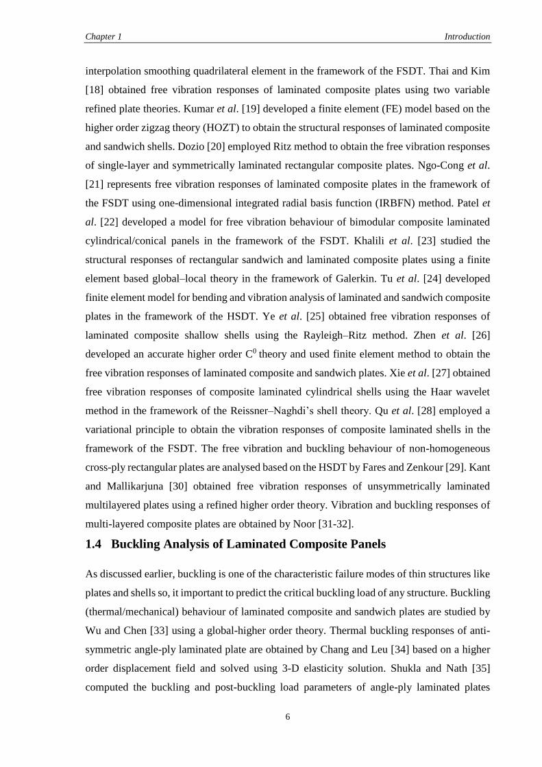
1.4 Buckling Analysis of Laminated Composite Panels
As discussed earlier, buckling is one of the characteristic failure modes of thin structures like
plates and shells so, it important to predict the critical buckling load of any structure. Buckling
(thermal/mechanical) behaviour of laminated composite and sandwich plates are studied by
Wu and Chen [33] using a global-higher order theory. Thermal buckling responses of anti-
symmetric angle-ply laminated plate are obtained by Chang and Leu [34] based on a higher
order displacement field and solved using 3-D elasticity solution. Shukla and Nath [35]
computed the buckling and post-buckling load parameters of angle-ply laminated plates
Chapter 1 Introduction
7
analytically under thermo-mechanical loading. The non- linearity in geometry matrix due to
excess thermal/mechanical deformation is taken in von-Karman sense in the framework of
the FSDT. Thermal buckling behaviour of laminated composite plates based on the layerwise
theory investigated by Lee [36] using FEM. The buckling behaviour of cross-ply laminated
orthotropic truncated conical shells are analysed using the von Karman–Donnell-type of
nonlinear kinematics by Sofiyev and Kuruoglu [37]. Vosoughi et al. [38] presented thermal
buckling and post-buckling load parameters of laminated composite beams. The temperature-
dependent composite properties are taken in their analysis and the geometrical distortion is
modelled using generalized Green’s strain in the framework of the FSDT. Shen [39] studied
the buckling responses of imperfect laminated plates in the framework of the HSDT. The
buckling behaviour of composite plates is analysed by Jameel et al. [40] under thermal and
mechanical loading. Li et al. [41] analysed buckling behaviour of composite stiffened
laminated cylindrical shells based on a layerwise/solid-element (LW/SE) method and FEM.
Buckling behaviour of laminated composite plate is studied by Fazzolari et al. [42] taking
non- linearity in geometry matrix due to excess thermal/mechanical deformation in von-
Karman sense in the framework of the HSDT. Shadmehri et al. [43] reported stability
behaviour of conical composite shells subjected to axial compression load using linear strain–
displacement relations in the framework of the FSDT. Farahmand et al. [44] studied thermal
buckling behaviour of rectangular micro-plates using higher continuity p-version finite
element method. Thermal buckling behaviour of composite laminated plates are studied by
Shiau et al. [45] using the high-order triangular plate element in the framework of the FSDT.
Kheirikhah et al. [46] studied bi-axial buckling behaviour of laminated composite and
sandwich plates using the von-Karman kinematic non-linearity in the framework of the
HSDT. Nali et al. [47] obtained buckling responses of laminated plates using von-Karman
nonlinear kinematic in the framework of thin plate theory. Kant and Babu [48-49] developed
a higher order refined finite element model to obtain the thermal buckling responses of
laminated composite and sandwich plates. Panda and Singh [50] studied thermal post-
buckling behaviour of laminated composite cylindrical/hyperboloidal shallow shell panel
using FEM in framework of the HSDT taking the geometry nonlinearity in Green-Lagrange
sense. Singh et al. [51] reported the buckling behaviour of laminated composite plates
subjected to thermal and mechanical loading using mesh-less collocation method in the
framework of the HSDT.
In addition to the above, some researcher have also analysed the buckling behaviour of
laminated structures under mechanical loading using the same type of geometrical
Chapter 1 Introduction
8
nonlinearity and in-plane mechanical loading. Grover et al. [52] analysed static and buckling
behaviour of laminated composite and sandwich plates using an inverse hyperbolic shear
deformation theory. Buckling behaviour of angle-ply composite and sandwich plates are
computed by Zhen and Wanji [53]. Topal and Uzman [54] developed a model in the
framework of the FSDT using four node Lagrangian finite element (FE) to investigate the
buckling responses. Khdeir and Librescue [55] investigated the buckling and the free
vibration responses of symmetric cross-ply laminated elastic plates based on the HSDT mid-
plane kinematics. Fazzolari et al. [56] studied stability behaviour of composite plates in the
framework of the HSDT and the geometric nonlinearity is taken in von-Karman sense. The
buckling behaviour of symmetric angle-ply and cross-ply stepped flat composite columns are
analysed using FEM by Akbulut et al. [57]. Matsunaga [58] analysed vibration and stability
behaviour of cross-ply laminated shallow shells using power series expansion. Ferreira et al.
[59] studied buckling behaviour of laminated composite plates using radial basis functions in
the framework of the HSDT. Lal et al. [60] studied stability behaviour of laminated composite
cylindrical shell panel subjected to hygro-thermo-mechanical loading taking the geometrical
nonlinearity in von-Karman sense in the framework of the HSDT. Amadio and Bedon [61-
62] developed an analytical model based on the Newmark’s theory to obtain the load bearing
capacity of laminated glass beams in out-of-plane bending and in-plane compression or shear.
Chirica and Beznea [63] studied buckling behaviour of the multiple delaminated composite
plates under shear and axial compression. The buckling behaviour of cross-ply laminated
conical shell panels subjected to axial compression is studied by Abediokhchi et al. [64] in
the framework of the classical shell theory. Komur et al. [65] obtained buckling responses of
laminated composite plates with an elliptical/circular cut-out using FEM and governing
equations are solved using Newton–Raphson method. Buckling and post-buckling behaviour
of laminated composite plate is studied by Dash and Singh [66] using Green-Lagrange type
nonlinearity in the framework of the HSDT. Seifi et al. [67] reported buckling responses of
composite annular plates under uniform internal and external radial edge loads in the
framework of the CLPT. Khalili et al. [68] obtained buckling load parameters of laminated
rectangular plate on Pasternak foundation using the Lindstedt–Poincare perturbation
technique. Cagdas [69] obtained buckling responses of cross-ply laminated shells of
revolution using a curved axisymmetric shell finite element. Tang and Wang [70] studied
buckling behaviour of symmetrically laminated rectangular plates with in-plane compressive
loadings using the Rayleigh–Ritz method in the framework of the CLPT. Pandit et al. [71]
Chapter 1 Introduction
9
reported buckling behaviour of laminated sandwich plates based on an improved higher order
zigzag theory.
1.5 Introduction of Finite Element Method and ANSYS
In this advance world, the finite element method (FEM) is widely adopted and being
used as the most trustworthy tool for designing of any structure because of the precision of
this method compare to other analytical or numerical methods. It plays an important role in
predicting the responses of various products, parts, assemblies and subassemblies. Nowadays,
FEM is extensively used in all advanced industries which saves the huge time of prototyping
with reducing the cost due to physical test and increases the innovation at a faster and more
accurate way. There are many optimized finite element analysis (FEA) tools are available in
the market and ANSYS is one of them which is acceptable by many industries and analysts.
Nowadays, ANSYS is being used in a different engineering fields such as power
generation, electronic devices, transportation, and household appliances as well as to analyse
the vehicle simulation and in aerospace industries. ANSYS gradually entered into a number
of fields making it convenient for fatigue analysis, nuclear power plant and medical
applications. Thermal/mechanical/thermo-mechanical analysis of various structures based on
the thermal and/or mechanical loading can be done with ease. ANSYS is also very useful in
electro thermal analysis of switching elements of a super conductor, ion projection
lithography, detuning of an HF oscillator by the mechanical vibration of an acoustic sounder.
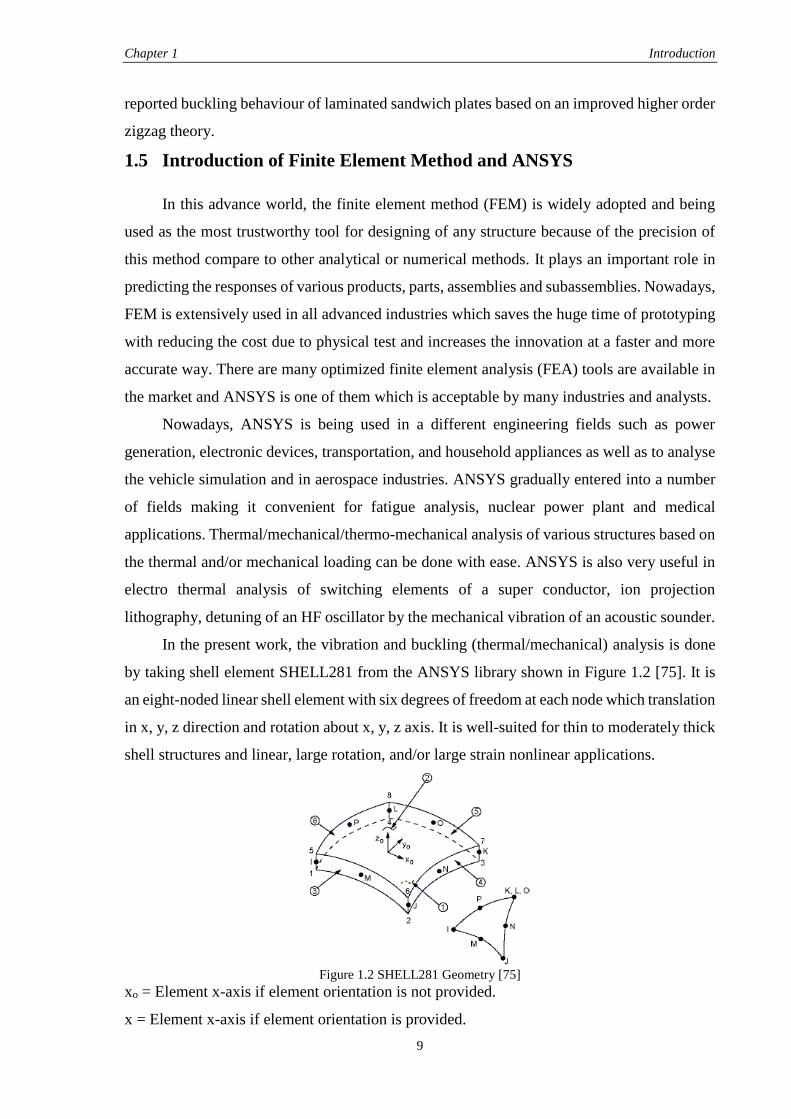
In the present work, the vibration and buckling (thermal/mechanical) analysis is done
by taking shell element SHELL281 from the ANSYS library shown in Figure 1.2 [75]. It is
an eight-noded linear shell element with six degrees of freedom at each node which translation
in x, y, z direction and rotation about x, y, z axis. It is well-suited for thin to moderately thick
shell structures and linear, large rotation, and/or large strain nonlinear applications.
Figure 1.2 SHELL281 Geometry [75]
xo = Element x-axis if element orientation is not provided.
x = Element x-axis if element orientation is provided.
Chapter 1 Introduction
10
1.6 Motivation of the Present Work
The laminated composite shell panels are of great attention to the designers because of
efficient lightweight structures, due to their tailored properties as mentioned earlier. Increased
uses of the composite structures especially in aeronautical/aerospace engineering have
created the requirement of their analysis. These structural components are subjected to
various types of combined loading and exposed to elevated thermal/mechanical/thermo-
mechanical environment during their service, which often changes the original geometry of
the shell panel. The changes in panel geometry and the interaction with loading condition
affect the structural vibration and buckling responses greatly.
In order to achieve the light weight structures for stringent demand of weight reduction
in the advanced engineering structures to conserve energy the laminated composites
consisting of multiple layers are extensively employed and their usage will continue to grow
as structural members. It is also important to mention that, these laminated composites are
weak in shear and highly flexible in nature as compared to any other metallic plate/shell. To
obtain the accurate prediction of responses of laminated composites, it is necessary and
essential requirement that the displacement model must be capable to take care of the effect
of shear deformation. In this regard a higher order shear deformation theory is most desirable.
As discussed earlier, the structural components such as flat/curved laminated shell panels are
often subjected to intense thermal/mechanical/thermo-mechanical loading and/or large
amplitude vibration during their service. The geometry of the shell panel alter and stiffness
matrix associated with the material are no more linear due to excess deformations and this
effects has to be appropriately considered in the analysis. The vibration and buckling of
structures have been received a considerable attention not only due to their wide range
application, but also the challenging problems with interesting behaviour. In most of the
literature, the geometry matrix associated in buckling is modelled taking into account for the
non-linearity in the von-Karman sense. But the nonlinearity in von-Karman sense may not be
appropriate enough for the realistic prediction of their responses. It is noted that the studies
related buckling behaviour of laminated panel structure under thermo-mechanical loading
need to be exploited more by using a better mathematical model for the prediction of exact
behaviour of laminated structures. In addition to that the comprehensive testing of the desired
responses using commercial finite element package will be a really add on to the present
study.
Chapter 1 Introduction
11
1.7 Objectives and Scope of the Present Thesis
This thesis aims to develop a general mathematical model for laminated composite
curved panel under uniform temperature based on the HSDT displacement field model. The
Green-Lagrange type of strain displacement relations are employed to take care the
geometrical distortion. A suitable finite element model is proposed and implemented for the
discretisation of the panel model. It also aims to obtain the effect of different types panel
geometries (cylindrical, spherical, elliptical, hyperboloid and flat) and other geometrical
parameters (aspect ratios, thickness ratios, curvature ratios, modular ratios, support conditions
and lamination schemes) on the free vibration and buckling (thermal, mechanical and thermo-
mechanical) responses of the laminated composites. A detailed scope of the present study is
given below:
As a first step, free vibration behavior of laminated composite panels of various
geometries (cylindrical, spherical, elliptical, hyperboloid and flat plate) has been
studied using the developed mathematical model.
The model is extended, to study the buckling temperature of laminated curved
composite panels subjected to uniform temperature field through thickness by taking
the geometric matrix in Green-Lagrange sense.
The model is extended, to study the mechanical buckling behavior of laminated
composite shells subjected to uniaxial and/or bi-axial loading.
The vibration and buckling (thermal/mechanical) behaviour of laminated panels has
been validated using the APDL code in ANSYS 13.0 environment.
Finally, the parametric study of laminated composite panel have been carried out using
finite element analysis software ANSYS and developed HSDT model.
Few numerical examples of laminated composite shell panel are solved using the
proposed model. In order to check the efficacy of the present developed mathematical model
and simulation model as well the convergence behaviour with mesh refinement have been
computed for all possible geometries of shell panels. In addition to that, the present results
are also compared with those available published literature to show the accuracy of the present
developed mathematical model. Finally, a good volume of new results are computed for the
future references in this field of study.
Chapter 1 Introduction
12
1.8 Organisation of the Thesis
The overview and motivation of the present work followed by the objectives and scope
of the present thesis are discussed in this chapter. The background and state of the art of the
present problem by various investigators related to the scope of the present area of interest
are addresses in this chapter. This chapter divided into five different sections, the first section,
a basic introduction about problem and theories used in past. In the section two, some
important contributions for vibration and buckling (thermal/mechanical/thermo-mechanical)
behaviour of laminated composite structures are discussed. In the section three, a brief
introduction of finite element method and finite element analysis software ANSYS is
presented. The motivation of the present work is discussed in fourth and in fifth objective and
scope of present work is incorporated. Some critical observations are discussed in the final
section. The remaining part of the thesis are organised in the following fashion.
In Chapter 2, a general mathematical formulation for the thermo-mechanical buckling
and free vibration of laminated composite panel, by modelling in the framework of the HSDT
under the uniform temperature distribution. The Green-Lagrange type strain displacement
relations are considered to take into account the geometrical nonlinearity arising in the shell
panel due to excess deformation. The steps of various energy calculations, governing equation
and solution steps are discussed. Subsequently, the boundary condition and computational
investigation are discussed.
Chapter 3, illustrates, the free vibration responses of laminated composite panels for
various panel geometries such as cylindrical, spherical, elliptical, hyperboloid and flat panel
are discussed. Detailed parametric studies of material and geometrical parameters are also
discussed.
Enhancement of buckling (thermal/mechanical/thermo-mechanical) of laminated
composite panels for different panel geometries and the influence of geometrical and material
properties on the panel responses are discussed in Chapter 4.
Chapter 5 summarizes the whole work and it contains the concluding remarks drawn
from the present study and the future scope of the work of the present study.
Some important books and publications referred during the present study have been
listed in the References section.
In order to achieve the objective and scope of the present work discussed above in this
chapter, there is need to know the state of art of the problem for that a detailed review of
earlier work done in the same field have been discussed thoroughly in the next chapter.
Chapter 1 Introduction
13
The following papers are prepared based on the work presented in the thesis.
In International Journals:
1. P. V. Katariya and S. K. Panda, “Vibration and Thermal Buckling Analysis of Curved
Panels,” Aircraft Engineering and Aerospace Technology. (Revised)
2. P. V. Katariya and S. K. Panda, “Stability and Free Vibration Behaviour of Laminated
Composite Plate under Thermo-mechanical Loading,” International Journal of Applied
and Computational Mathematics. (communicated)
In Conference Proceedings:
3. P. V. Katariya and S. K. Panda, “Modal Analysis of Laminated Composite Spherical
Shell Panels using Finite Element Method,” Proceedings of International Conference
on Structural Engineering and Mechanics (ICSEM), Dec 20-22 2013, NIT Rourkela,
Odisha, India.
4. P. V. Katariya and S. K. Panda, “Stability and vibration behavior of laminated
composite and sandwich structures,” Proceedings of 2nd KIIT International Symposium
on Advances in Automotive Technology (KIIT-SAAT), Dec 20-21 2013, KIIT
Bhubaneswar, Odisha, India.
5. P. V. Katariya and S. K. Panda, “Thermo-Mechanical Stability Analysis of Composite
Cylindrical Panels,” ASME 2013 Gas Turbine India conference (ASME GTINDIA
2013), Dec 5-6 2013, Bangalore, Karnataka, India.
6. P. V. Katariya and S. K. Panda, “A parametric study on free vibration behavior of
laminated composite curved panels,” Proceedings of International Conference on
Advances in Mechanical Engineering (ICAME), May 29-31 2013, COEP, Pune,
Maharashtra, India.
7. P. V. Katariya and S. K. Panda, “Stability Analysis of Laminated Composite
Cylindrical Shell Structure under Uniaxial loading,” Proceedings of All India Seminar
on Recent Advances in Mechanical Engineering, Mar 16-17 2013, Bhubaneswar,
Odisha, India.
8. P. V. Katariya and S. K. Panda, “Thermo-mechanical stability analysis of laminated
composite plate using FEM,” Proceedings of 1st KIIT International Symposium on
Advances in Automotive Technology (KIIT-SAAT), Jan 11-12, 2013, KIIT
Bhubaneswar, Odisha, India.
14
CHAPTER 2
GENERAL MATHEMATICAL FORMULATION
2.1 Introduction
In today’s modern world, many weight sensitive industries are using high performance
laminated composite structures and their components such as laminated curved/flat panels are
need to be designed and analysed very carefully. These structural components are very often
subjected to vibration and buckling (thermal/mechanical/thermo-mechanical) due to excess
deformation during their service life. Hence, these components must be reliable enough and
should have good load bearing capacity and the demands for detailed and realistic studies of
different structural responses have increase very significantly.
It is important to mention that the original geometry of the panel is distorted because of
the excess deformation and induced stress and if the deformation is large, the basic geometry
of the panel changes which affects the stiffness properties of the structure largely. As earlier
mentioned the geometric strain associated with buckling phenomena is nonlinear in nature. It
is well known that the total deformation occurred in a material continuum is the sum of
translation, rotation and distortion components. If the structural elements undergoes severe
nonlinearity then not only the distortion component but also the other two components in
deformation play important role to derive the actual strain-displacement relation. The
laminated composite structural components are extremely flexible as compared to other
metallic components so the large deformation terms and the higher order shear deformation
terms arises during the mathematical modelling are more important for an accurate prediction
of the frequency and the buckling load parameter. A thorough literature review in the previous
chapter clearly shows that various studies have been done previously on different types of
problem. But very few studies have been reported the buckling behaviour by taking the
geometrical nonlinearity in Green-Lagrange sense in the framework of the HSDT and taking
all the higher order term in the mathematical formulation for laminated composite shell panel.
In addition to this, the detailed study has been validated with the commercially available finite
element (FE) software package ANSYS which are less in number.
In this chapter a general mathematical formulation of doubly curved shell panel is
developed on the basis of basic assumptions. The system of governing equations for the
Chapter 2 General Mathematical Formulation
15
vibration and buckling (thermal/mechanical/thermo-mechanical) characteristics of laminated
composite panels derived using the variational approach. A finite element model is employed
to discretise the present panel model through the chosen displacement field. For the buckling
analysis of laminated composite panels, the geometric nonlinearity has been considered in
Green-Lagrange strain-displacement type for the formulation and discussed in this chapter.
2.2 Assumptions
The mathematical formulation is based on the following assumptions:
The basic geometric configuration of the problem considered here is a doubly curved shell
panel on a rectangular plan form.
The doubly curved panel geometry has been chosen as a basic configuration, so that
depending on the values of curvature parameters, flat, cylindrical, spherical, hyperboloid
and elliptical panel configuration can be considered.
The middle plane of the doubly curved panel is taken as the reference plane.
A two dimensional approach has been adopted to model a three dimensional behaviour of
shell.
Perfect bond exists between fibres and matrices so that no slippage occurs at the interface.
A uniform temperature field is considered for the present analysis through the thickness.
The composite material properties are assumed to be temperature independent.
The laminated panel consists of number of layers bonded together where each layer is
treated as homogeneous and orthotropic.
2.3 Displacement Field and Geometry of the Shell
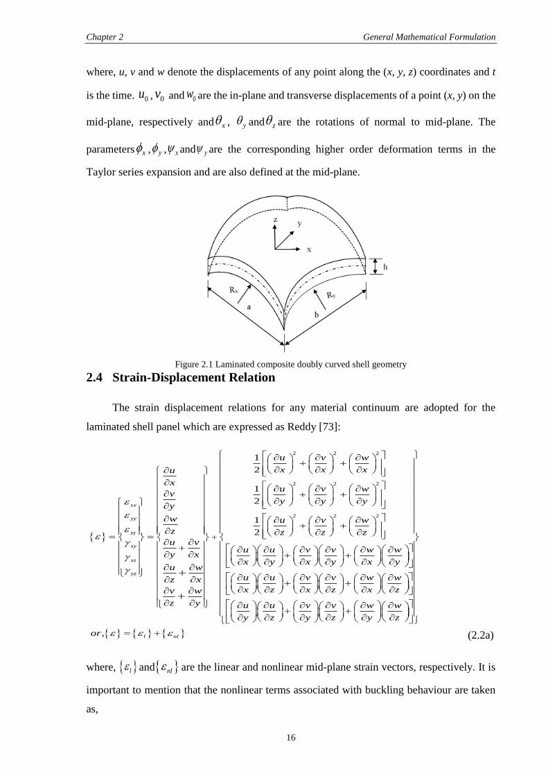
The doubly curved panel is classified according to its curvature parameter, such as
cylindrical (where one curvature is infinite), spherical (where both curvature are same), flat
panel (where both curvatures are infinite) and doubly curved (where the two curvatures are
different). In this work, a panel is assumed, which is composed of N number of anisotropic
layers of uniform thickness h, length a, and width b which is shown in Figure 2.1. The values
of the principal radii of the curvature are denoted by Rx and Ry. The following displacement
field for the laminated shell panel based on the HSDT proposed by Dash and Singh [66] is
considered to derive the mathematical model.
2 3
0
2 3
0
0
, , , , , , , , , , ,
, , , , , , , , , , ,
, , , , , , ,
x x x
y y y
z
u x y z t u x y t z x y t z x y t z x y t
v x y z t v x y t z x y t z x y t z x y t
w x y z t w x y t z x y t
(2.1)
Chapter 2 General Mathematical Formulation
16
where, u, v and w denote the displacements of any point along the (x, y, z) coordinates and t
is the time. 0u , 0v and 0w are the in-plane and transverse displacements of a point (x, y) on the
mid-plane, respectively and x , y and z are the rotations of normal to mid-plane. The
parameters x , y , x and y are the corresponding higher order deformation terms in the
Taylor series expansion and are also defined at the mid-plane.
Figure 2.1 Laminated composite doubly curved shell geometry
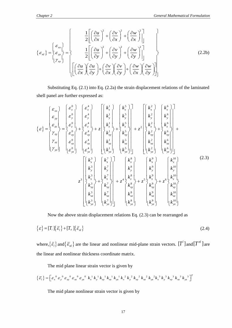
2.4 Strain-Displacement Relation
The strain displacement relations for any material continuum are adopted for the
laminated shell panel which are expressed as Reddy [73]:
2 2 2
2 2
1
2
1
2xx
yy
zz
xy
xz
yz
u v w
x x xu
xu v w
vy y y
y
w
z
u v
y x
u w
z x
v w
z y
2
2 2 21
2
u v w
z z z
u u v v w w
x y x y x y
u u v v w w
x z x z x z
u
y
, l nl
u v v w w
z y z y z
or
(2.2a)
where, l and nl are the linear and nonlinear mid-plane strain vectors, respectively. It is
important to mention that the nonlinear terms associated with buckling behaviour are taken
as,
Chapter 2 General Mathematical Formulation
17
2 2 2
2 2 2
1
2
1
2
xx
nl yy
xy
u v w
x x x
u v w
y y y
u u v v w w
x y x y x y
(2.2b)
Substituting Eq. (2.1) into Eq. (2.2a) the strain displacement relations of the laminated
shell panel are further expressed as:
0 4 1 5
0 4 1 5
0 4 1 5
0 4 1 5
0 4 1 5
0 4 1 5
x x x xxx
y y y yyy
zz z z z z
xy xy xy xy xy
xz xz xz xz xz
yzyz yz yz yz
k k
k k
k kz
k k
k k
k k
2 6
2 6
2 6
2
2 6
2 6
2 6
3
3
3
3
3
3
3
x x
y y
z z
xy xy
xz xz
yz yz
x
y
z
xy
xz
yz
k k
k k
k kz
k k
k k
k k
k
k
kz
k
k
k
7 8 9 10
7 8 9 10
7 8 9 10
4 5 6
7 8 9 10
7 8 9 10
7 8 9 10
x x x x
y y y y
z z z z
xy xy xy xy
xz xz xz xz
yz yz yz yz
k k k k
k k k k
k k k kz z z
k k k k
k k k k
k k k k
(2.3)
Now the above strain displacement relations Eq. (2.3) can be rearranged as
[ ] [ ]l nll nlT T (2.4)
where, l and nl are the linear and nonlinear mid-plane strain vectors. [ ]lT and[ ]nlT are
the linear and nonlinear thickness coordinate matrix.
The mid plane linear strain vector is given by
0 0 0 0 0 1 1 1 1 1 2 2 2 2 2 3 3 3 3 3T
l x y xy xz yz x y xy xz yz x y xy xz yz x y xy xz yzk k k k k k k k k k k k k k k
The mid plane nonlinear strain vector is given by
Chapter 2 General Mathematical Formulation
18
4 4 4 5 5 5 6 6 6 7 7 7 8 8 8 9 9 9 10 10 10T
nl x y xy x y xy x y xy x y xy x y xy x y xy x y xyk k k k k k k k k k k k k k k k k k
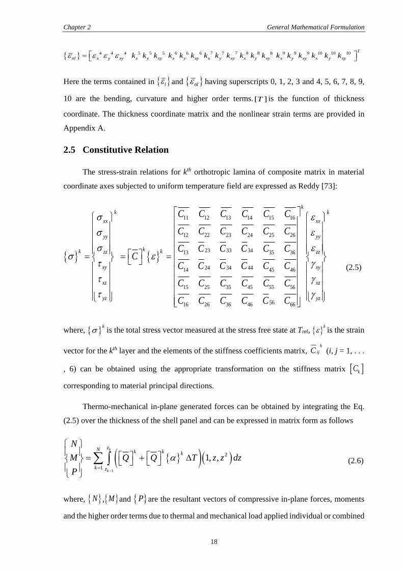
Here the terms contained in l and nl having superscripts 0, 1, 2, 3 and 4, 5, 6, 7, 8, 9,
10 are the bending, curvature and higher order terms. [ ]T is the function of thickness
coordinate. The thickness coordinate matrix and the nonlinear strain terms are provided in
Appendix A.
2.5 Constitutive Relation
The stress-strain relations for kth orthotropic lamina of composite matrix in material
coordinate axes subjected to uniform temperature field are expressed as Reddy [73]:
11 12 13 14 15 16
12 22 23 24 25 26
23 33 3413 35 36
24 34 4414 45 46
15 25 35 45 55 56
5616 26 36 46 66
kk
xx xx
yy yy
kk kzz zz
xy xy
xz xz
yz
C C C C C C
C C C C C C
C C C C C CC
C C C C C C
C C C C C C
C C C C C C
k
yz
(2.5)
where, k
is the total stress vector measured at the stress free state at Tref, k
is the strain
vector for the kth layer and the elements of the stiffness coefficients matrix, k
ijC (i, j = 1, . . .
, 6) can be obtained using the appropriate transformation on the stiffness matrix kC
corresponding to material principal directions.
Thermo-mechanical in-plane generated forces can be obtained by integrating the Eq.
(2.5) over the thickness of the shell panel and can be expressed in matrix form as follows
1
2
1
1, ,k
k
zN k k k
k z
N
M Q Q T z z dz
P
(2.6)
where, N , M and P are the resultant vectors of compressive in-plane forces, moments
and the higher order terms due to thermal and mechanical load applied individual or combined
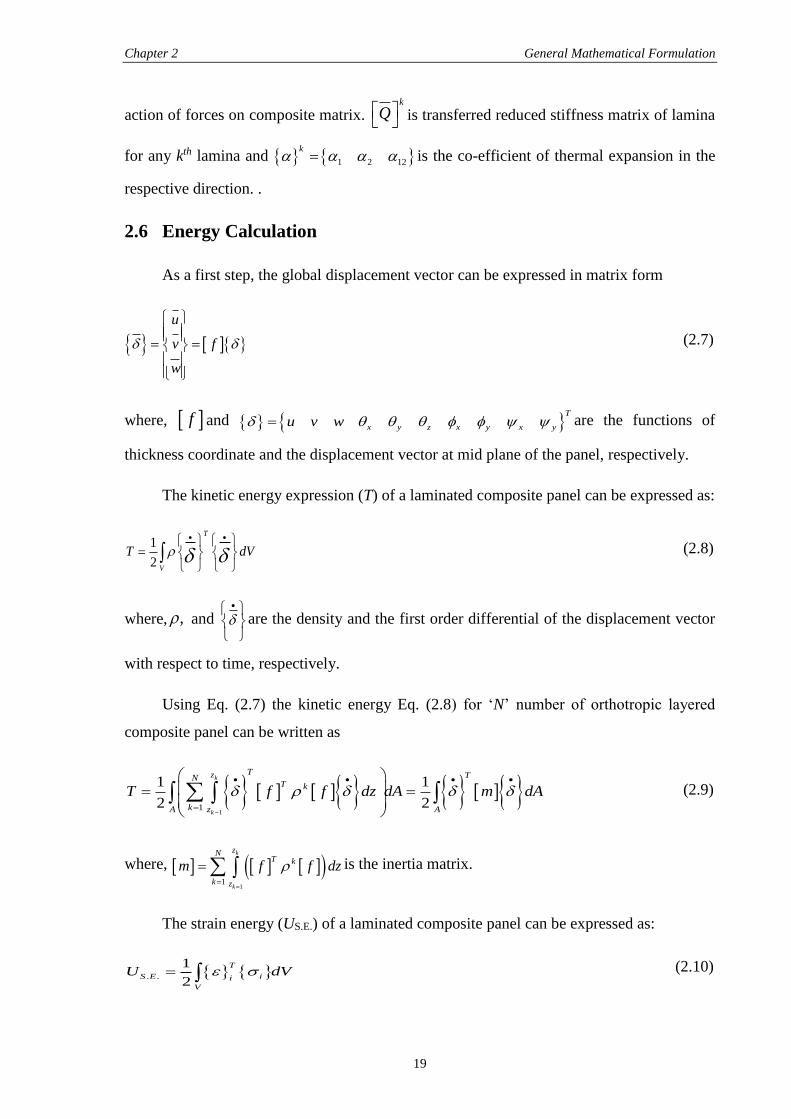
Chapter 2 General Mathematical Formulation
19
action of forces on composite matrix. k
Q is transferred reduced stiffness matrix of lamina
for any kth lamina and 1 2 12
k is the co-efficient of thermal expansion in the
respective direction. .
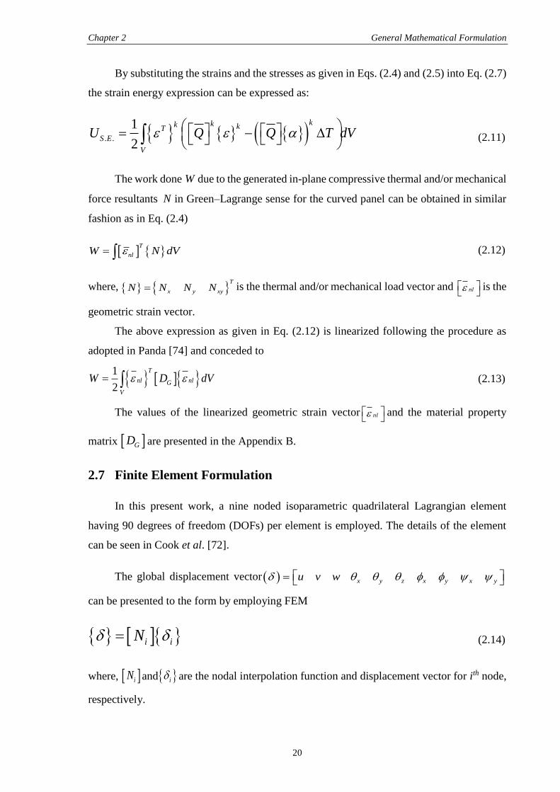
2.6 Energy Calculation
As a first step, the global displacement vector can be expressed in matrix form
u
v f
w
(2.7)
where, f and T
x y z x y x yu v w are the functions of
thickness coordinate and the displacement vector at mid plane of the panel, respectively.
The kinetic energy expression (T) of a laminated composite panel can be expressed as:
1
2
T
V
T dV
(2.8)
where, , and
are the density and the first order differential of the displacement vector
with respect to time, respectively.
Using Eq. (2.7) the kinetic energy Eq. (2.8) for ‘N’ number of orthotropic layered
composite panel can be written as
1
1
1 1
2 2
k
k
Tz TNT k
kA z A
T f f dz dA m dA
(2.9)
where, 1
1
k
k
zNT k
k z
m f f dz
is the inertia matrix.
The strain energy (US.E.) of a laminated composite panel can be expressed as:
. .
1
2
T
S E ii
V
U dV (2.10)
Chapter 2 General Mathematical Formulation
20
By substituting the strains and the stresses as given in Eqs. (2.4) and (2.5) into Eq. (2.7)
the strain energy expression can be expressed as:
. .
1
2
kkk kT
S E
V
U Q Q T dV (2.11)
The work done W due to the generated in-plane compressive thermal and/or mechanical
force resultants N in Green–Lagrange sense for the curved panel can be obtained in similar
fashion as in Eq. (2.4)
T
nlW N dV (2.12)
where, T
x y xyN N N N is the thermal and/or mechanical load vector and nl
is the
geometric strain vector.
The above expression as given in Eq. (2.12) is linearized following the procedure as
adopted in Panda [74] and conceded to
1
2nl n
T
lG
V
W D dV (2.13)
The values of the linearized geometric strain vector nl
and the material property
matrix GD are presented in the Appendix B.
2.7 Finite Element Formulation
In this present work, a nine noded isoparametric quadrilateral Lagrangian element
having 90 degrees of freedom (DOFs) per element is employed. The details of the element
can be seen in Cook et al. [72].
The global displacement vector x y z x y x yu v w
can be presented to the form by employing FEM
i iN (2.14)
where, iN and i are the nodal interpolation function and displacement vector for ith node,
respectively.
Chapter 2 General Mathematical Formulation
21
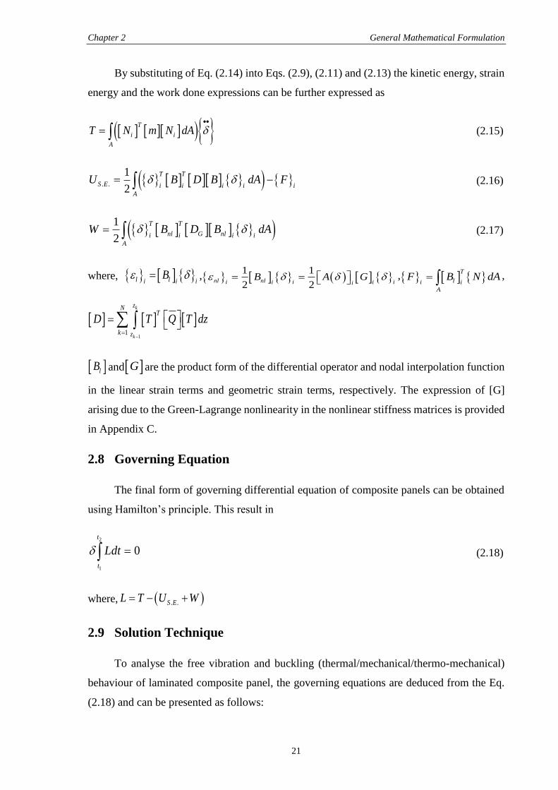
By substituting of Eq. (2.14) into Eqs. (2.9), (2.11) and (2.13) the kinetic energy, strain
energy and the work done expressions can be further expressed as
T
i i
A
T N m N dA
(2.15)
. .
1
2
TT
S E i i ii i
A
U B D B dA F (2.16)
1
2
TT
nl G nli ii i
A
W B D B dA (2.17)
where, l li iiB ,
1 1
2 2nl nli i ii ii
B A G , T
li i
A
F B N dA ,
1
1
k
k
zNT
k z
D T Q T dz
lB and G are the product form of the differential operator and nodal interpolation function
in the linear strain terms and geometric strain terms, respectively. The expression of [G]
arising due to the Green-Lagrange nonlinearity in the nonlinear stiffness matrices is provided
in Appendix C.
2.8 Governing Equation
The final form of governing differential equation of composite panels can be obtained
using Hamilton’s principle. This result in
2
1
0
t
t
Ldt (2.18)
where, . .S EL T U W
2.9 Solution Technique
To analyse the free vibration and buckling (thermal/mechanical/thermo-mechanical)
behaviour of laminated composite panel, the governing equations are deduced from the Eq.
(2.18) and can be presented as follows:
Chapter 2 General Mathematical Formulation
22
2 0SK M (2.19)
0S cr GK K (2.20)
where, T
i i
dA
M N m N dA and T
G nl G nl i
dA i
K B D B dA . cr , , SK and GK
are the critical buckling load parameter, the displacement vector, the stiffness matrix and
global geometric stiffness matrix, respectively.
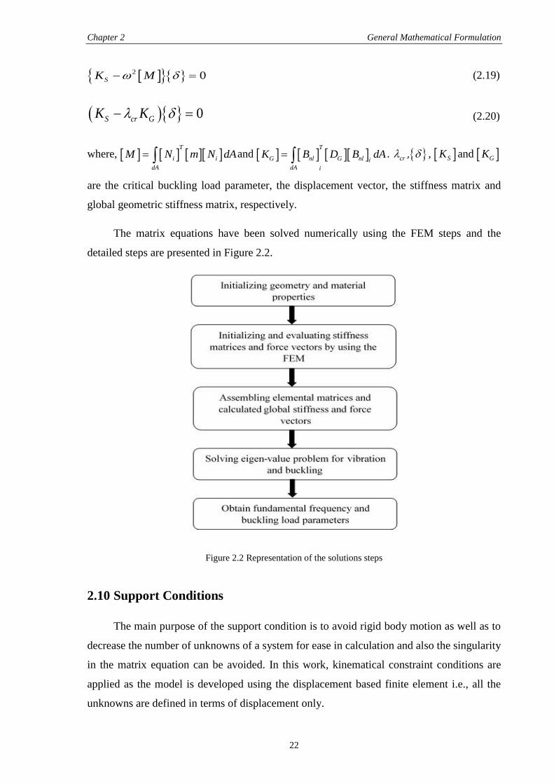
The matrix equations have been solved numerically using the FEM steps and the
detailed steps are presented in Figure 2.2.
Figure 2.2 Representation of the solutions steps
2.10 Support Conditions
The main purpose of the support condition is to avoid rigid body motion as well as to
decrease the number of unknowns of a system for ease in calculation and also the singularity
in the matrix equation can be avoided. In this work, kinematical constraint conditions are
applied as the model is developed using the displacement based finite element i.e., all the
unknowns are defined in terms of displacement only.
Chapter 2 General Mathematical Formulation
23
The following sets of boundary conditions are used for the present work. However, the
mathematical formulation, which is general in nature, does not put any limitations.
a) Simply supported boundary condition (S):
0v = 0w = x = z = x = x =0 at x = 0, a
0u = 0w = y = z = y = y =0 at y = 0, b
b) Clamped boundary condition (C):
0u = 0v = 0w = x = y = z = x = y = x = y =0 at x = 0, a and y = 0, b
2.11 Computational Investigations
For the computational purpose, a computer code has been developed in MATLAB 7.10
environment for the vibration and buckling (thermal/mechanical/thermo-mechanical)
analysis of laminated composite panel. Although, the present code can be done using other
languages such as FORTRAN and/or C++ but MATLAB is more user friendly and it is easy
to implement. The MATLAB suffers from two major problems namely: inadequate memory
space and computational time is more in comparison to other two types as discussed earlier.
Due to the revolutionary change in digital computers, an Intel (R) Core (TM) i5-2400 CPU
@ 3.10 GHz, 3.10 GHz and 4 GB RAM system is used for the present numerical analysis.
However, it can be further improved by using an Intel (R) Core (TM) i7 which is also
available in market. The main advantages of MATLAB are that, the error accumulations due
to the numerical analysis and selection of methodology are taken care by MATLAB to get
the desired output by selecting the appropriates syntax from its given library. The code has
been developed in such a way that it can be compute the different types of problems of
laminated composite panels. The developed code has been employed to solve the free
vibration and buckling (thermal/mechanical/thermo-mechanical) of laminated composite
panels. In addition to that the analysis has been carried out using simulation model developed
using the ANSYS parametric design language code in ANSYS 13.0 environment for the
laminated composite panels which is less time consuming and accepted by many industries.
2.12 Summary
The main aim of this present chapter is to develop a general mathematical model for
the computer implementation of the proposed problem i.e., the free vibration and the buckling
(thermal/mechanical/thermo-mechanical) analysis of laminated composite structures. The
necessity and requirement of the problem and their background were discussed in the first
Chapter 2 General Mathematical Formulation
24
section. A few essential assumptions were made in the Section 2.2. Then, in Section 2.3 the
geometry of the shell panel and the assumed higher order displacement field were stated. In
Section 2.4 the strain-displacement relations in Green-Lagrange sense and subsequent strain
vectors evaluated. The mechanics of laminated composite was presented in Section 2.5. The
general thermo-elastic constitutive relations for laminated composite and the resultant in-
plane thermal/mechanical forces were discussed in Section 2.6. Then, in Section 2.7 various
energies and the work done due to the in-plane thermal and/or mechanical load were
calculated. The mathematical model for the proposed panel problem was discretised with the
help of finite element in Section 2.8. Then, in Section 2.9 the governing equation of motion
for the laminated panel were obtained using Hamilton’s principle. A detail discussion on the
solution technique and the necessary assumptions were presented in Section 2.10. Finally, the
types of support conditions were presented in Section 2.11 for the numerical analysis.
Computational investigation was discussed briefly in Section 2.12.
In the following chapters the solution of governing equation for various kinds of panel
problems such as free vibration and buckling (thermal/mechanical/thermo-mechanical) of
laminated composite shell panel have been investigated in details for different parameters and
discussed.
25
CHAPTER 3
FREE VIBRATION ANALYSIS OF LAMINATED
COMPOSITE SHELL PANELS
3.1 Introduction
In this chapter, the free vibration responses of laminated composite shell panel have
been investigated using the present developed mathematical model as discussed in the
previous chapter. The first mode frequency of any structural system is more important to
know not only to avoid the resonance but also an optimal design of the structures or the
structural components. It has the highest time period and affects the system responses greatly.
It is very well known that the laminated structural components are under the influence of
various combined loading and constrained conditions during their service life. This affects
the original geometry of the structure largely and the structural components are distorted
which changes the entire situation in the structural analysis.
The aim of this chapter is to state the governing equation of free vibration of laminated
composite shell panel and the solution steps to obtain the desired output. A detailed
parametric study and their effects on the free vibration and the fundamental frequencies are
obtained for different types of shell geometries.
3.2 Governing Equation and Solution
The governing equilibrium system equations of free vibration of laminated composite
shell panel are obtained initially by dropping the appropriate terms from the Eq. (2.19) and
that may be expressed as:
2[ ] 0sK M (3.1)
where, sK is the stiffness matrix, is the critical frequency parameter, M is the mass
matrix and is the displacement vector.
The Eq. (3.1) has been solved using the steps as discussed in the Chapter 2 and the
desired responses are obtained and discussed.
Chapter 3 Free Vibration Analysis of Laminated Composite Shell Panels
26
3.3 Results and Discussions
A finite element code is developed in MATLAB 7.10 based on the developed
mathematical shell panel model as stated and detailed is discussed in Chapter 2. The free
vibration analysis of laminated composite shell panels have been obtained for ten degrees of
freedom (DOFs) model. The validation and accuracy of the present algorithm is examined by
comparing the results with those available in the literature. In addition to this, a simulation
model is also developed in ANSYS using ANSYS parametric design language (APDL) code
to cross check the present mathematical model. The developed model is validated by
comparing the responses obtained using the MATLAB code and ANSYS (using Block-
Lanczos method) with those available published literature. It is observed from the validation
and convergence study that the present results are showing good agreement with the available
literatures. The effect of different combinations of parameters such as the curvature ratio
(R/a), the thickness ratio (a/h), the aspect ratio (a/b), the modular ratio (E1/E2), the lay-up
scheme and the support condition on the composite shell panel vibration responses are
discussed. The non-dimensionalised fundamental frequency is taken as 2 2
2/b E h ,
and the same is being used in the throughout analysis if it is not stated elsewhere.
3.4 Convergence and Validation Study of Free Vibration
In this section various numerical examples have been solved to check the convergence
and the efficacy of the proposed developed model. The results are compared with those
available published literature to validate the present developed mathematical model and
ANSYS model. As a first step, the convergence behaviour of the vibration responses are
presented in Figure 3.1 and Figure 3.2 for a simply supported cylindrical and flat panel,
respectively. The results are compared using the material properties M1 for the cylinder and
M2 for the flat panel same as Mantari et al. [8] and tabulated in Table 3.1.
Table 3.1 Material properties of the laminated composite structures
M1: E1/E2=25 G12=G13=0.5E2 G23=0.2E2
ν12=ν13=0.25 ρ=1
M2: E1/E2=open G12=G13=0.6E2 G23=0.5E2
ν12=ν13=0.25 ρ=1
Figure 3.1 presents the non-dimensional fundamental frequency response for three
different cross-ply [(00/900), (00/90/000) and (00/900/900/00)] laminated composite cylindrical
panel by taking same geometrical parameters (a/h=10 and R/a=10) as in Mantari et al. [8].
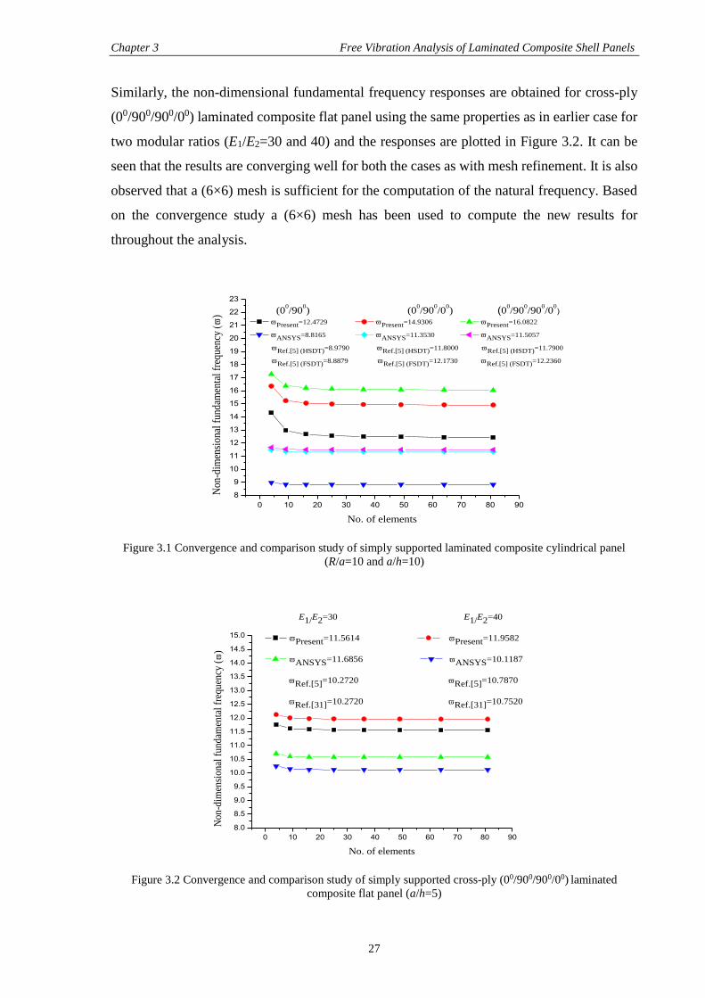
Chapter 3 Free Vibration Analysis of Laminated Composite Shell Panels
27
Similarly, the non-dimensional fundamental frequency responses are obtained for cross-ply
(00/900/900/00) laminated composite flat panel using the same properties as in earlier case for
two modular ratios (E1/E2=30 and 40) and the responses are plotted in Figure 3.2. It can be
seen that the results are converging well for both the cases as with mesh refinement. It is also
observed that a (6×6) mesh is sufficient for the computation of the natural frequency. Based
on the convergence study a (6×6) mesh has been used to compute the new results for
throughout the analysis.
0 10 20 30 40 50 60 70 80 90
8
9
10
11
12
13
14
15
16
17
18
19
20
21
22
23
Non
-dim
ensi
onal
fun
dam
enta
l fr
eque
ncy
)
No. of elements
(00/90
0) (0
0/90
0/0
0) (0
0/90
0/90
0/0
0)
Present=12.4729 Present=14.9306 Present=16.0822
ANSYS=8.8165 ANSYS=11.3530 ANSYS=11.5057
Ref.[5] (HSDT)=8.9790 Ref.[5] (HSDT)=11.8000 Ref.[5] (HSDT)=11.7900
Ref.[5] (FSDT)=8.8879 Ref.[5] (FSDT)=12.1730 Ref.[5] (FSDT)=12.2360
Figure 3.1 Convergence and comparison study of simply supported laminated composite cylindrical panel
(R/a=10 and a/h=10)
0 10 20 30 40 50 60 70 80 90
8.0
8.5
9.0
9.5
10.0
10.5
11.0
11.5
12.0
12.5
13.0
13.5
14.0
14.5
15.0
No
n-d
imen
sio
nal
fu
nd
amen
tal
freq
uen
cy (
)
No. of elements
E1/E2=30 E1/E2=40
Present=11.5614 Present=11.9582
ANSYS=11.6856 ANSYS=10.1187
Ref.[5]=10.2720 Ref.[5]=10.7870
Ref.[31]=10.2720 Ref.[31]=10.7520
Figure 3.2 Convergence and comparison study of simply supported cross-ply (00/900/900/00) laminated
composite flat panel (a/h=5)
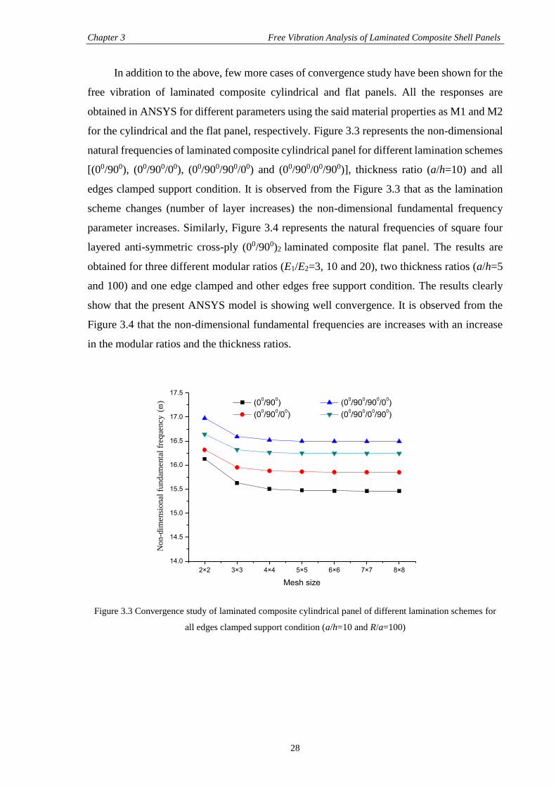
Chapter 3 Free Vibration Analysis of Laminated Composite Shell Panels
28
In addition to the above, few more cases of convergence study have been shown for the
free vibration of laminated composite cylindrical and flat panels. All the responses are
obtained in ANSYS for different parameters using the said material properties as M1 and M2
for the cylindrical and the flat panel, respectively. Figure 3.3 represents the non-dimensional
natural frequencies of laminated composite cylindrical panel for different lamination schemes
[(00/900), (00/900/00), (00/900/900/00) and (00/900/00/900)], thickness ratio (a/h=10) and all
edges clamped support condition. It is observed from the Figure 3.3 that as the lamination
scheme changes (number of layer increases) the non-dimensional fundamental frequency
parameter increases. Similarly, Figure 3.4 represents the natural frequencies of square four
layered anti-symmetric cross-ply (00/900)2 laminated composite flat panel. The results are
obtained for three different modular ratios (E1/E2=3, 10 and 20), two thickness ratios (a/h=5
and 100) and one edge clamped and other edges free support condition. The results clearly
show that the present ANSYS model is showing well convergence. It is observed from the
Figure 3.4 that the non-dimensional fundamental frequencies are increases with an increase
in the modular ratios and the thickness ratios.
2×2 3×3 4×4 5×5 6×6 7×7 8×8
14.0
14.5
15.0
15.5
16.0
16.5
17.0
17.5
Non-d
imen
sional
fundam
enta
l fr
equen
cy (
)
Mesh size
(00/90
0) (0
0/90
0/90
0/0
0)
(00/90
0/0
0) (0
0/90
0/0
0/90
0)
Figure 3.3 Convergence study of laminated composite cylindrical panel of different lamination schemes for
all edges clamped support condition (a/h=10 and R/a=100)
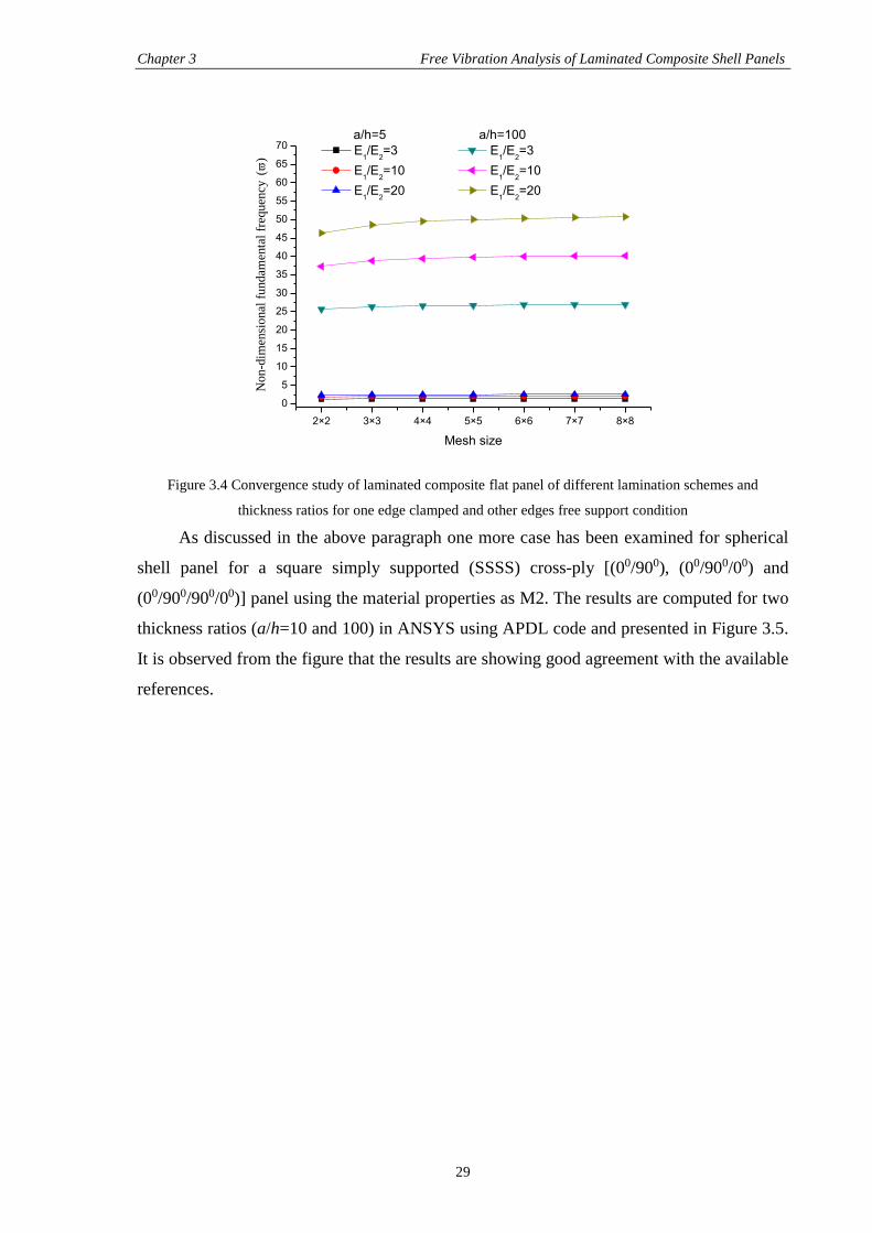
Chapter 3 Free Vibration Analysis of Laminated Composite Shell Panels
29
2×2 3×3 4×4 5×5 6×6 7×7 8×8
0
5
10
15
20
25
30
35
40
45
50
55
60
65
70
Non-d
imen
sional
fundam
enta
l fr
equen
cy (
)
Mesh size
a/h=5 a/h=100
E1/E
2=3 E
1/E
2=3
E1/E
2=10 E
1/E
2=10
E1/E
2=20 E
1/E
2=20
Figure 3.4 Convergence study of laminated composite flat panel of different lamination schemes and
thickness ratios for one edge clamped and other edges free support condition
As discussed in the above paragraph one more case has been examined for spherical
shell panel for a square simply supported (SSSS) cross-ply [(00/900), (00/900/00) and
(00/900/900/00)] panel using the material properties as M2. The results are computed for two
thickness ratios (a/h=10 and 100) in ANSYS using APDL code and presented in Figure 3.5.
It is observed from the figure that the results are showing good agreement with the available
references.
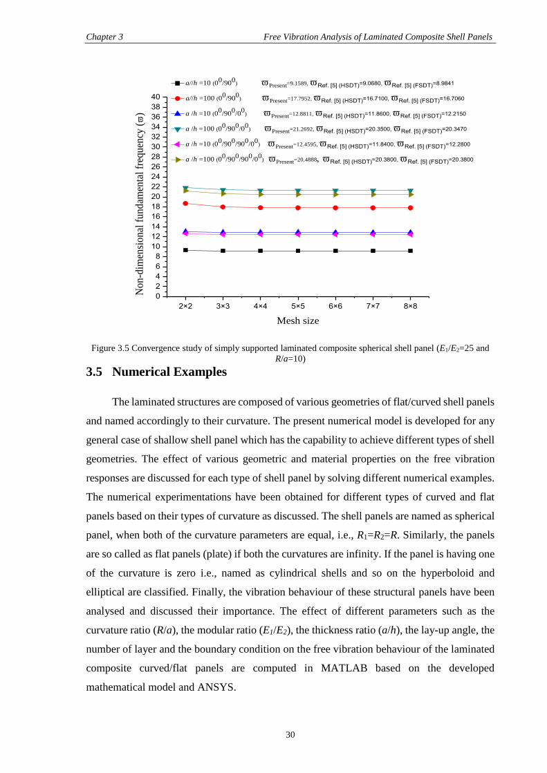
Chapter 3 Free Vibration Analysis of Laminated Composite Shell Panels
30
2×2 3×3 4×4 5×5 6×6 7×7 8×8
0
2
4
6
8
10
12
14
16
18
20
22
24
26
28
30
32
34
36
38
40
a//h =10 (00/900) Present=9.1589, Ref. [5] (HSDT)=9.0680, Ref. [5] (FSDT)=8.9841
a//h =100 (00
/900
) Present=17.7952, Ref. [5] (HSDT)=16.7100, Ref. [5] (FSDT)=16.7060
a /h =10 (00
/900
/00
) Present=12.8811, Ref. [5] (HSDT)=11.8600, Ref. [5] (FSDT)=12.2150
a /h =100 (00
/900
/00
)
Present=21.2692, Ref. [5] (HSDT)=20.3500, Ref. [5] (FSDT)=20.3470
a /h =10 (00
/900
/900
/00
) Present=12.4595, Ref. [5] (HSDT)=11.8400, Ref. [5] (FSDT)=12.2800
a /h =100 (00
/900
/900
/00
) Present=20.4888Ref. [5] (HSDT)=20.3800, Ref. [5] (FSDT)=20.3800
No
n-d
imen
sio
nal
fu
nd
amen
tal
freq
uen
cy (
)
Mesh size
Figure 3.5 Convergence study of simply supported laminated composite spherical shell panel (E1/E2=25 and
R/a=10)
3.5 Numerical Examples
The laminated structures are composed of various geometries of flat/curved shell panels
and named accordingly to their curvature. The present numerical model is developed for any
general case of shallow shell panel which has the capability to achieve different types of shell
geometries. The effect of various geometric and material properties on the free vibration
responses are discussed for each type of shell panel by solving different numerical examples.
The numerical experimentations have been obtained for different types of curved and flat
panels based on their types of curvature as discussed. The shell panels are named as spherical
panel, when both of the curvature parameters are equal, i.e., R1=R2=R. Similarly, the panels
are so called as flat panels (plate) if both the curvatures are infinity. If the panel is having one
of the curvature is zero i.e., named as cylindrical shells and so on the hyperboloid and
elliptical are classified. Finally, the vibration behaviour of these structural panels have been
analysed and discussed their importance. The effect of different parameters such as the
curvature ratio (R/a), the modular ratio (E1/E2), the thickness ratio (a/h), the lay-up angle, the
number of layer and the boundary condition on the free vibration behaviour of the laminated
composite curved/flat panels are computed in MATLAB based on the developed
mathematical model and ANSYS.
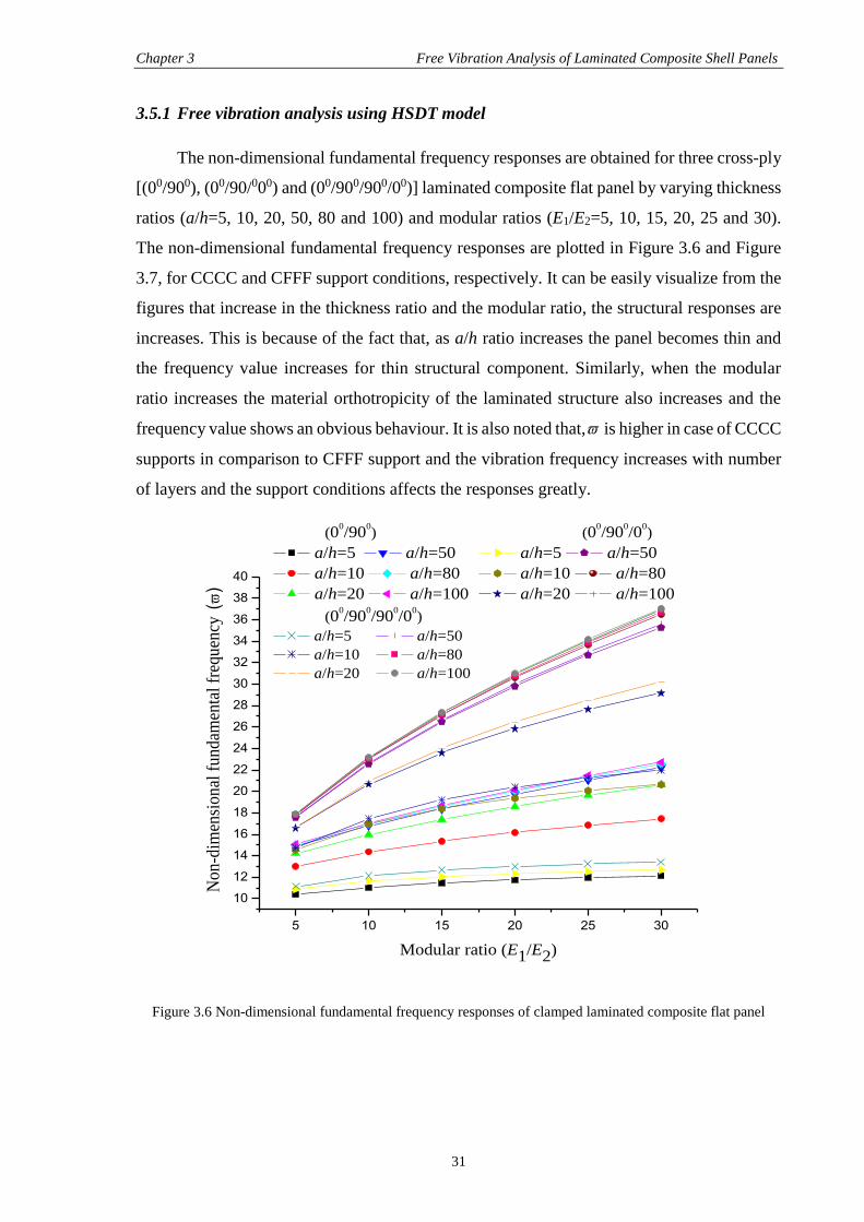
Chapter 3 Free Vibration Analysis of Laminated Composite Shell Panels
31
3.5.1 Free vibration analysis using HSDT model
The non-dimensional fundamental frequency responses are obtained for three cross-ply
[(00/900), (00/90/000) and (00/900/900/00)] laminated composite flat panel by varying thickness
ratios (a/h=5, 10, 20, 50, 80 and 100) and modular ratios (E1/E2=5, 10, 15, 20, 25 and 30).
The non-dimensional fundamental frequency responses are plotted in Figure 3.6 and Figure
3.7, for CCCC and CFFF support conditions, respectively. It can be easily visualize from the
figures that increase in the thickness ratio and the modular ratio, the structural responses are
increases. This is because of the fact that, as a/h ratio increases the panel becomes thin and
the frequency value increases for thin structural component. Similarly, when the modular
ratio increases the material orthotropicity of the laminated structure also increases and the
frequency value shows an obvious behaviour. It is also noted that, is higher in case of CCCC
supports in comparison to CFFF support and the vibration frequency increases with number
of layers and the support conditions affects the responses greatly.
5 10 15 20 25 30
10
12
14
16
18
20
22
24
26
28
30
32
34
36
38
40
No
n-d
imen
sio
nal
fu
nd
amen
tal
freq
uen
cy (
)
Modular ratio (E1/E2)
(00/90
0) (0
0/90
0/0
0)
a/h=5 a/h=50 a/h=5 a/h=50
a/h=10 a/h=80 a/h=10 a/h=80
a/h=20 a/h=100 a/h=20 a/h=100
(00/90
0/90
0/0
0)
a/h=5 a/h=50
a/h=10 a/h=80
a/h=20 a/h=100
Figure 3.6 Non-dimensional fundamental frequency responses of clamped laminated composite flat panel
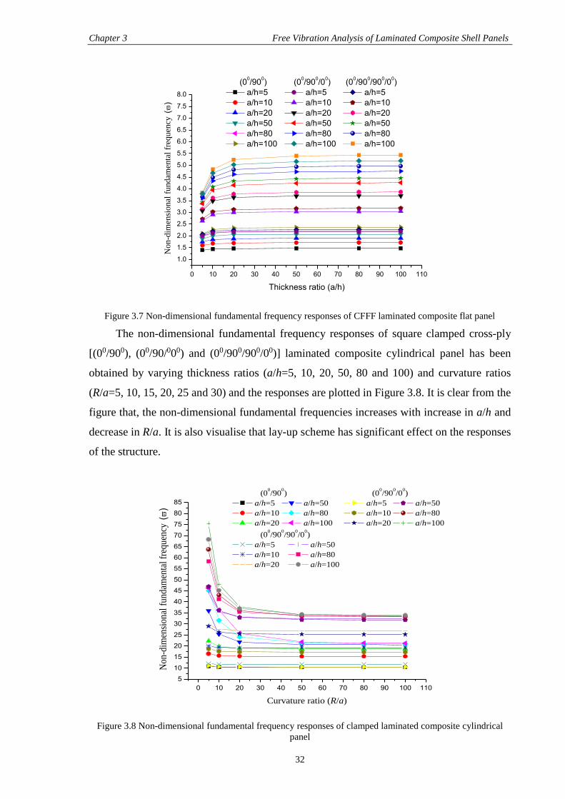
Chapter 3 Free Vibration Analysis of Laminated Composite Shell Panels
32
0 10 20 30 40 50 60 70 80 90 100 110
1.0
1.5
2.0
2.5
3.0
3.5
4.0
4.5
5.0
5.5
6.0
6.5
7.0
7.5
8.0
Non-d
imen
sional
fundam
enta
l fr
equen
cy (
)
Thickness ratio (a/h)
(00/90
0) (0
0/90
0/0
0) (0
0/90
0/90
0/0
0)
a/h=5 a/h=5 a/h=5
a/h=10 a/h=10 a/h=10
a/h=20 a/h=20 a/h=20
a/h=50 a/h=50 a/h=50
a/h=80 a/h=80 a/h=80
a/h=100 a/h=100 a/h=100
Figure 3.7 Non-dimensional fundamental frequency responses of CFFF laminated composite flat panel
The non-dimensional fundamental frequency responses of square clamped cross-ply
[(00/900), (00/90/000) and (00/900/900/00)] laminated composite cylindrical panel has been
obtained by varying thickness ratios (a/h=5, 10, 20, 50, 80 and 100) and curvature ratios
(R/a=5, 10, 15, 20, 25 and 30) and the responses are plotted in Figure 3.8. It is clear from the
figure that, the non-dimensional fundamental frequencies increases with increase in a/h and
decrease in R/a. It is also visualise that lay-up scheme has significant effect on the responses
of the structure.
0 10 20 30 40 50 60 70 80 90 100 110
5
10
15
20
25
30
35
40
45
50
55
60
65
70
75
80
85
No
n-d
imen
sio
nal
fu
nd
amen
tal
freq
uen
cy (
)
Curvature ratio (R/a)
(00/90
0) (0
0/90
0/0
0)
a/h=5 a/h=50 a/h=5 a/h=50
a/h=10 a/h=80 a/h=10 a/h=80
a/h=20 a/h=100 a/h=20 a/h=100
(00/90
0/90
0/0
0)
a/h=5 a/h=50
a/h=10 a/h=80
a/h=20 a/h=100
Figure 3.8 Non-dimensional fundamental frequency responses of clamped laminated composite cylindrical
panel
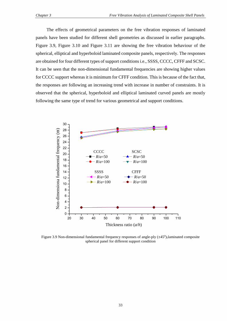
Chapter 3 Free Vibration Analysis of Laminated Composite Shell Panels
33
The effects of geometrical parameters on the free vibration responses of laminated
panels have been studied for different shell geometries as discussed in earlier paragraphs.
Figure 3.9, Figure 3.10 and Figure 3.11 are showing the free vibration behaviour of the
spherical, elliptical and hyperboloid laminated composite panels, respectively. The responses
are obtained for four different types of support conditions i.e., SSSS, CCCC, CFFF and SCSC.
It can be seen that the non-dimensional fundamental frequencies are showing higher values
for CCCC support whereas it is minimum for CFFF condition. This is because of the fact that,
the responses are following an increasing trend with increase in number of constraints. It is
observed that the spherical, hyperboloid and elliptical laminated curved panels are mostly
following the same type of trend for various geometrical and support conditions.
20 30 40 50 60 70 80 90 100 110
0
2
4
6
8
10
12
14
16
18
20
22
24
26
28
30
No
n-d
imen
sio
na
fun
dam
enta
l fr
equ
ency
(
)
Thickness ratio (a/h)
CCCC SCSC
R/a=50 R/a=50
R/a=100 R/a=100
SSSS CFFF
R/a=50 R/a=50
R/a=100 R/a=100
Figure 3.9 Non-dimensional fundamental frequency responses of angle-ply (±450)5laminated composite
spherical panel for different support condition
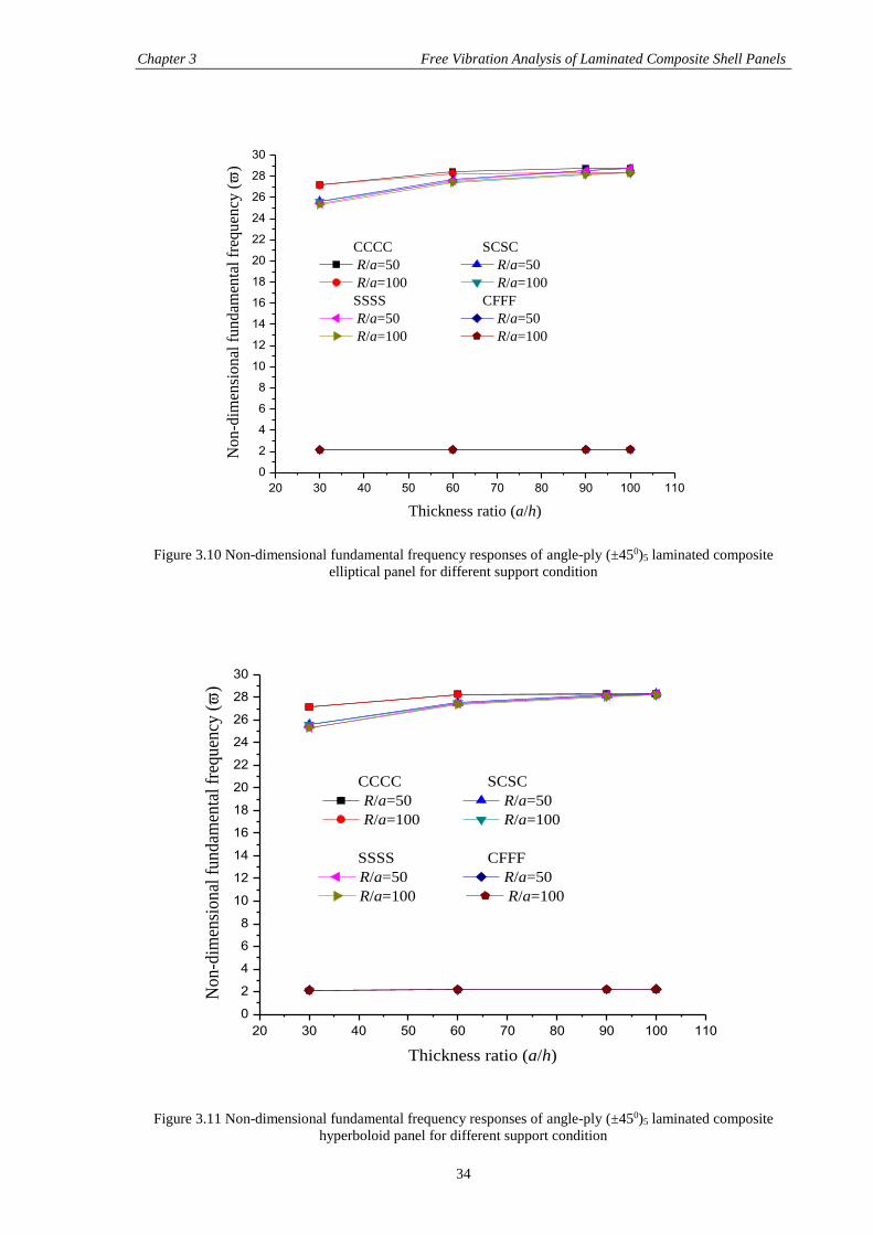
Chapter 3 Free Vibration Analysis of Laminated Composite Shell Panels
34
20 30 40 50 60 70 80 90 100 110
0
2
4
6
8
10
12
14
16
18
20
22
24
26
28
30
No
n-d
imen
sio
nal
fu
nd
amen
tal
freq
uen
cy (
)
Thickness ratio (a/h)
CCCC SCSC
R/a=50 R/a=50
R/a=100 R/a=100
SSSS CFFF
R/a=50 R/a=50
R/a=100 R/a=100
Figure 3.10 Non-dimensional fundamental frequency responses of angle-ply (±450)5 laminated composite
elliptical panel for different support condition
20 30 40 50 60 70 80 90 100 110
0
2
4
6
8
10
12
14
16
18
20
22
24
26
28
30
No
n-d
imen
sio
nal
fu
nd
amen
tal
freq
uen
cy (
)
Thickness ratio (a/h)
CCCC SCSC
R/a=50 R/a=50
R/a=100 R/a=100
SSSS CFFF
R/a=50 R/a=50
R/a=100 R/a=100
Figure 3.11 Non-dimensional fundamental frequency responses of angle-ply (±450)5 laminated composite
hyperboloid panel for different support condition
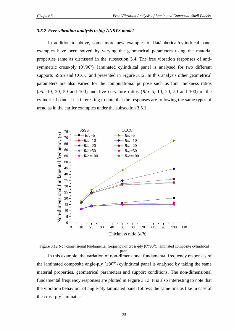
Chapter 3 Free Vibration Analysis of Laminated Composite Shell Panels
35
3.5.2 Free vibration analysis using ANSYS model
In addition to above, some more new examples of flat/spherical/cylindrical panel
examples have been solved by varying the geometrical parameters using the material
properties same as discussed in the subsection 3.4. The free vibration responses of anti-
symmetric cross-ply (00/900)2 laminated cylindrical panel is analysed for two different
supports SSSS and CCCC and presented in Figure 3.12. In this analysis other geometrical
parameters are also varied for the computational purpose such as four thickness ratios
(a/h=10, 20, 50 and 100) and five curvature ratios (R/a=5, 10, 20, 50 and 100) of the
cylindrical panel. It is interesting to note that the responses are following the same types of
trend as in the earlier examples under the subsection 3.5.1.
0 10 20 30 40 50 60 70 80 90 100 110
0
5
10
15
20
25
30
35
40
45
50
55
60
65
70
75
No
n-d
imen
sio
nal
fu
nd
amen
tal
freq
uen
cy (
)
Thickness ratio (a/h)
SSSS CCCC
R/a=5 R/a=5
R/a=10 R/a=10
R/a=20 R/a=20
R/a=50 R/a=50
R/a=100 R/a=100
Figure 3.12 Non-dimensional fundamental frequency of cross-ply (00/900)2 laminated composite cylindrical
panel In this example, the variation of non-dimensional fundamental frequency responses of
the laminated composite angle-ply (±300)2 cylindrical panel is analysed by taking the same
material properties, geometrical parameters and support conditions. The non-dimensional
fundamental frequency responses are plotted in Figure 3.13. It is also interesting to note that
the vibration behaviour of angle-ply laminated panel follows the same line as like in case of
the cross-ply laminates.
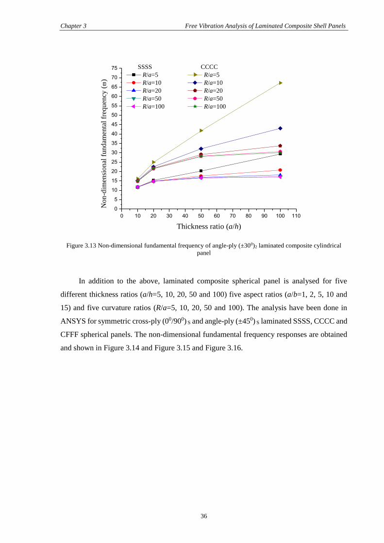
Chapter 3 Free Vibration Analysis of Laminated Composite Shell Panels
36
0 10 20 30 40 50 60 70 80 90 100 110
0
5
10
15
20
25
30
35
40
45
50
55
60
65
70
75
No
n-d
imen
sio
nal
fu
nd
amen
tal
freq
uen
cy (
)
Thickness ratio (a/h)
SSSS CCCC
R/a=5 R/a=5
R/a=10 R/a=10
R/a=20 R/a=20
R/a=50 R/a=50
R/a=100 R/a=100
Figure 3.13 Non-dimensional fundamental frequency of angle-ply (±300)2 laminated composite cylindrical
panel
In addition to the above, laminated composite spherical panel is analysed for five
different thickness ratios (a/h=5, 10, 20, 50 and 100) five aspect ratios (a/b=1, 2, 5, 10 and
15) and five curvature ratios (R/a=5, 10, 20, 50 and 100). The analysis have been done in
ANSYS for symmetric cross-ply (00/900) S and angle-ply (±450) S laminated SSSS, CCCC and
CFFF spherical panels. The non-dimensional fundamental frequency responses are obtained
and shown in Figure 3.14 and Figure 3.15 and Figure 3.16.
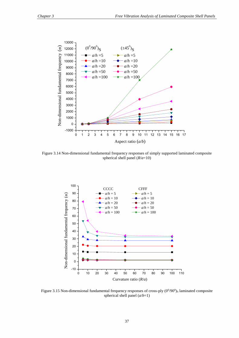
Chapter 3 Free Vibration Analysis of Laminated Composite Shell Panels
37
0 1 2 3 4 5 6 7 8 9 10 11 12 13 14 15 16 17
-1000
0
1000
2000
3000
4000
5000
6000
7000
8000
9000
10000
11000
12000
13000
No
n-d
imen
sio
nal
fu
nd
amen
tal
freq
uen
cy (
)
Aspect ratio (a/b)
(00/90
0)S (±45
0)S
a/h =5 a/h =5
a/h =10 a/h =10
a/h =20 a/h =20
a/h =50 a/h =50
a/h =100 a/h =100
Figure 3.14 Non-dimensional fundamental frequency responses of simply supported laminated composite
spherical shell panel (R/a=10)
0 10 20 30 40 50 60 70 80 90 100 110
-10
0
10
20
30
40
50
60
70
80
90
100
No
n-d
imen
sio
nal
fu
nd
amen
tal
freq
uen
cy (
)
Curvature ratio (R/a)
CCCC CFFF
a/h = 5 a/h = 5
a/h = 10 a/h = 10
a/h = 20 a/h = 20
a/h = 50 a/h = 50
a/h = 100 a/h = 100
Figure 3.15 Non-dimensional fundamental frequency responses of cross-ply (00/900)S laminated composite
spherical shell panel (a/b=1)
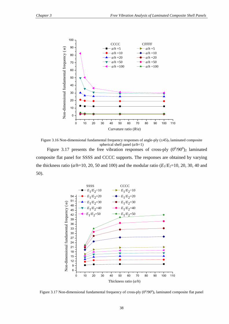
Chapter 3 Free Vibration Analysis of Laminated Composite Shell Panels
38
0 10 20 30 40 50 60 70 80 90 100 110
0
10
20
30
40
50
60
70
80
90
100
No
n-d
imen
sio
nal
fu
nd
amen
tal
freq
uen
cy (
)
Curvature ratio (R/a)
CCCC CFFFF
a/h =5 a/h =5
a/h =10 a/h =10
a/h =20 a/h =20
a/h =50 a/h =50
a/h =100 a/h =100
Figure 3.16 Non-dimensional fundamental frequency responses of angle-ply (±45)S laminated composite
spherical shell panel (a/b=1)
Figure 3.17 presents the free vibration responses of cross-ply (00/900)2 laminated
composite flat panel for SSSS and CCCC supports. The responses are obtained by varying
the thickness ratio (a/h=10, 20, 50 and 100) and the modular ratio (E1/E2=10, 20, 30, 40 and
50).
0 10 20 30 40 50 60 70 80 90 100 110
6
9
12
15
18
21
24
27
30
33
36
39
42
45
48
51
54
No
n-d
imen
sio
nal
fu
nd
amen
tal
freq
uen
cy (
)
Thickness ratio (a/h)
SSSS CCCC
E1/E2=10 E1/E2=10
E1/E2=20 E1/E2=20
E1/E2=30 E1/E2=30
E1/E2=40 E1/E2=40
E1/E2=50 E1/E2=50
Figure 3.17 Non-dimensional fundamental frequency of cross-ply (00/900)2 laminated composite flat panel
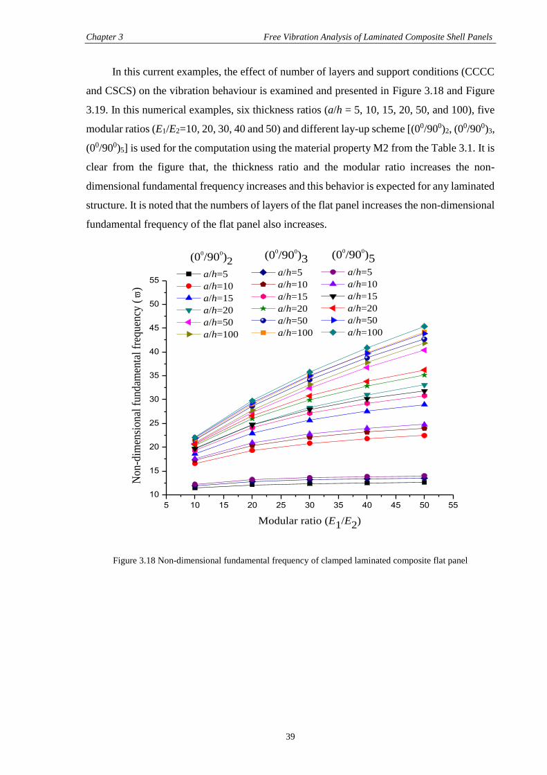
Chapter 3 Free Vibration Analysis of Laminated Composite Shell Panels
39
In this current examples, the effect of number of layers and support conditions (CCCC
and CSCS) on the vibration behaviour is examined and presented in Figure 3.18 and Figure
3.19. In this numerical examples, six thickness ratios (a/h = 5, 10, 15, 20, 50, and 100), five
modular ratios (E1/E2=10, 20, 30, 40 and 50) and different lay-up scheme [(00/900)2, (00/900)3,
(00/900)5] is used for the computation using the material property M2 from the Table 3.1. It is
clear from the figure that, the thickness ratio and the modular ratio increases the non-
dimensional fundamental frequency increases and this behavior is expected for any laminated
structure. It is noted that the numbers of layers of the flat panel increases the non-dimensional
fundamental frequency of the flat panel also increases.
5 10 15 20 25 30 35 40 45 50 55
10
15
20
25
30
35
40
45
50
55
(00/90
0)3
a/h=5
a/h=10
a/h=15
a/h=20
a/h=50
a/h=100
No
n-d
imen
sio
nal
fu
nd
amen
tal
freq
uen
cy (
)
Modular ratio (E1/E2)
(00/90
0)2
a/h=5
a/h=10
a/h=15
a/h=20
a/h=50
a/h=100
(00/90
0)5
a/h=5
a/h=10
a/h=15
a/h=20
a/h=50
a/h=100
Figure 3.18 Non-dimensional fundamental frequency of clamped laminated composite flat panel
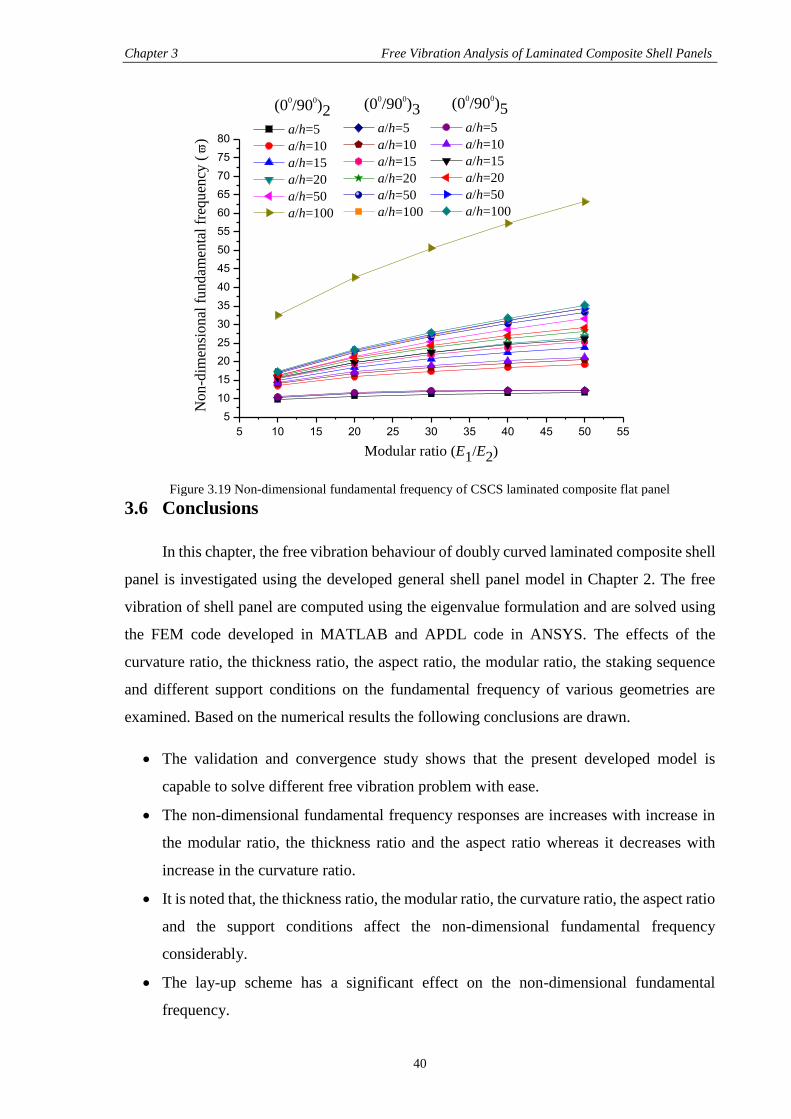
Chapter 3 Free Vibration Analysis of Laminated Composite Shell Panels
40
5 10 15 20 25 30 35 40 45 50 55
5
10
15
20
25
30
35
40
45
50
55
60
65
70
75
80
(00/90
0)5
a/h=5
a/h=10
a/h=15
a/h=20
a/h=50
a/h=100
(00/90
0)3
a/h=5
a/h=10
a/h=15
a/h=20
a/h=50
a/h=100N
on
-dim
ensi
on
al f
un
dam
enta
l fr
equ
ency
(
)
Modular ratio (E1/E2)
(00/90
0)2
a/h=5
a/h=10
a/h=15
a/h=20
a/h=50
a/h=100
Figure 3.19 Non-dimensional fundamental frequency of CSCS laminated composite flat panel
3.6 Conclusions
In this chapter, the free vibration behaviour of doubly curved laminated composite shell
panel is investigated using the developed general shell panel model in Chapter 2. The free
vibration of shell panel are computed using the eigenvalue formulation and are solved using
the FEM code developed in MATLAB and APDL code in ANSYS. The effects of the
curvature ratio, the thickness ratio, the aspect ratio, the modular ratio, the staking sequence
and different support conditions on the fundamental frequency of various geometries are
examined. Based on the numerical results the following conclusions are drawn.
The validation and convergence study shows that the present developed model is
capable to solve different free vibration problem with ease.
The non-dimensional fundamental frequency responses are increases with increase in
the modular ratio, the thickness ratio and the aspect ratio whereas it decreases with
increase in the curvature ratio.
It is noted that, the thickness ratio, the modular ratio, the curvature ratio, the aspect ratio
and the support conditions affect the non-dimensional fundamental frequency
considerably.
The lay-up scheme has a significant effect on the non-dimensional fundamental
frequency.
41
CHAPTER 4
BUCKLING ANALYSIS OF LAMINATED COMPOSITE
SHELL PANELS
4.1 Introduction
In this chapter, the buckling strength of laminated shell panels has been studied using
the proposed developed model under thermal/mechanical/thermo-mechanical environment.
As discussed earlier in Chapter 1, the structural components of aerospace, launch vehicles,
rockets etc. are made up of laminated composites normally having shell type geometries
which are often subjected to intense thermal/mechanical/thermo-mechanical loading due to
the aerodynamic heating during their service life. The temperature increases in the structural
component induces buckling/instability which in turn degrades the performance of the whole
structure. It is well known that the buckling doesn’t mean the ultimate failure of the structural
components and they are still capable to carry extra amount of load beyond the buckling point
without failure. It is also important to mention that the geometric strain associated with the
buckling phenomena is nonlinear in nature. From the design and analysis point of view, it is
important to know the exact value of buckling strength in thermal/mechanical/thermo-
mechanical environment. In addition to this, the mathematical model has to be sufficient
enough to incorporate the true geometric alterations.
In this present chapter, the thermal/mechanical/thermo-mechanical buckling load
parameter of the shell panel of various geometries has been obtained. It is also necessary to
mention that, to explore the original strength of laminated structures, the mathematical model
is developed in the framework of the HSDT by taking the nonlinearity in Green-Lagrange
sense to incorporate the true geometrical distortion in geometry. In addition to that all the
terms evolved in the formulation have been incorporated in the mathematical model to
achieve a realistic case.
4.2 Governing Equations and Solution
The system governing equilibrium equations of a buckled laminated composite shell
panel is obtained initially by dropping the appropriate terms from the Eq. (2.20) and that
may be expressed as:
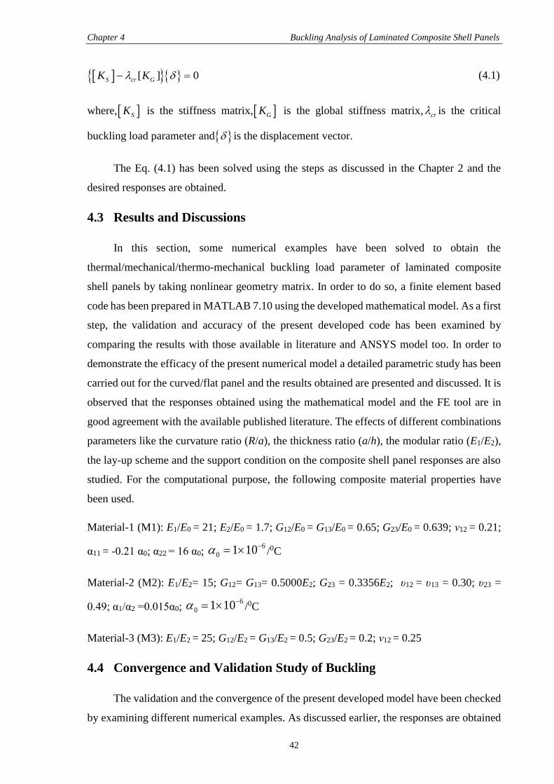
Chapter 4 Buckling Analysis of Laminated Composite Shell Panels
42
[ ] 0S cr GK K (4.1)
where, SK is the stiffness matrix, GK is the global stiffness matrix,cr is the critical
buckling load parameter and is the displacement vector.
The Eq. (4.1) has been solved using the steps as discussed in the Chapter 2 and the
desired responses are obtained.
4.3 Results and Discussions
In this section, some numerical examples have been solved to obtain the
thermal/mechanical/thermo-mechanical buckling load parameter of laminated composite
shell panels by taking nonlinear geometry matrix. In order to do so, a finite element based
code has been prepared in MATLAB 7.10 using the developed mathematical model. As a first
step, the validation and accuracy of the present developed code has been examined by
comparing the results with those available in literature and ANSYS model too. In order to
demonstrate the efficacy of the present numerical model a detailed parametric study has been
carried out for the curved/flat panel and the results obtained are presented and discussed. It is
observed that the responses obtained using the mathematical model and the FE tool are in
good agreement with the available published literature. The effects of different combinations
parameters like the curvature ratio (R/a), the thickness ratio (a/h), the modular ratio (E1/E2),
the lay-up scheme and the support condition on the composite shell panel responses are also
studied. For the computational purpose, the following composite material properties have
been used.
Material-1 (M1): E1/E0 = 21; E2/E0 = 1.7; G12/E0 = G13/E0 = 0.65; G23/E0 = 0.639; ν12 = 0.21;
α11 = -0.21 α0; α22 = 16 α0; 6
0 1 10 /0C
Material-2 (M2): E1/E2= 15; G12= G13= 0.5000E2; G23 = 0.3356E2; υ12 = υ13 = 0.30; υ23 =
0.49; α1/α2 =0.015α0; 6
0 1 10 /0C
Material-3 (M3): E1/E2 = 25; G12/E2 = G13/E2 = 0.5; G23/E2 = 0.2; ν12 = 0.25
4.4 Convergence and Validation Study of Buckling
The validation and the convergence of the present developed model have been checked
by examining different numerical examples. As discussed earlier, the responses are obtained
Chapter 4 Buckling Analysis of Laminated Composite Shell Panels
43
by solving numerically through the developed computer code and APDL code in ANSYS and
the responses are compared with those published literature. Based on the convergence, a (6×6)
mesh is adopted for the computation of the thermal and mechanical buckling responses for
throughout the analysis. It is also important to mention that the mechanical buckling load has
been obtained in APDL code (ANSYS) is converging at a (16×16) mesh in throughout the
analysis. The non-dimensional forms of the critical buckling temperature and the critical
buckling loads are obtained using the formulae, 3
0 10cr crT and2 3
2/x xxN N a E h ,
respectively. It is same in throughout the analysis if it is not stated elsewhere.
Figure 4.1 shows the comparison and convergence behaviour of non-dimensional
buckling temperature parameter with different mesh divisions for a square thin (a/h = 80 and
100) simply supported angle-ply (±450)3 laminated composite flat panel subjected to uniform
temperature field. The critical buckling temperature results are obtained using the geometrical
properties same as in the reference and M2. The figure shows that, the responses obtained
from the present computer code (MATLAB) and the APDL code are converging well with
the mesh refinement and a very small difference exists with Chang and Leu [34] and Shen
[39].
0 10 20 30 40 50 60 70
0.0
0.5
1.0
1.5
2.0
2.5
3.0
3.5
4.0
4.5
5.0
No
n-d
imen
sio
nal
bu
ckli
ng
tem
per
atu
re (cr
)
No. of elements
a /h=80 a /h=100
Present=0.2198 Present=0.1391
ANSYS=0.19195 ANSYS=0.12315
Ref. [34], [39]=0.1919 Ref. [34], [39]=0.1230
Figure 4.1 Convergence study of non-dimensional buckling temperature of simply supported angle-ply
(±450)3 laminated composite flat panel
Chapter 4 Buckling Analysis of Laminated Composite Shell Panels
44
Now, one more case of buckling behaviour is being analysed for the buckling
temperatures of laminated composite flat panel. In order to obtain the temperature responses,
the present developed HSDT mathematical model is employed where the geometry matrix is
evaluated based on the Green-Lagrange type of nonlinear kinematics. The numerical
investigations have been done using the same geometrical and material properties (M1) of
Kant and Babu [48] and presented in Table 4.1.
Table 4.1 Comparison of non-dimensional buckling temperature of simply supported angle-ply laminated
flat panel
a/h Present Source Lay-up
10 0.073 0.079 [30] (±150)5
100 0.0016 0.0015 [30] (±300)5
In this paragraph the convergence and validation study of mechanical buckling load has
been discussed based on the APDL code and computer code developed using the proposed
HSDT mathematical model. In this computation, a square simply supported laminated
cylindrical panel model has been developed for two anti-symmetric cross-ply [(00/900)2 and
(00/900)5] using APDL code in ANSYS. The material (M3) and geometrical properties have
been taken same as Nguyen-Van et al. [17]. The responses are plotted in Figure 4.2. The
critical buckling load parameters with mesh refinement are obtained for uniaxial loading
condition. It is understood that the present results are converging well and the differences are
very small with the references. Similarly, the mechanical buckling load parameter has been
computed using HSDT model as discussed initially in this paragraph and the responses are
presented in Table 4.2. The responses are obtained for a simply supported laminated flat panel
using the material and geometrical properties same as the references.
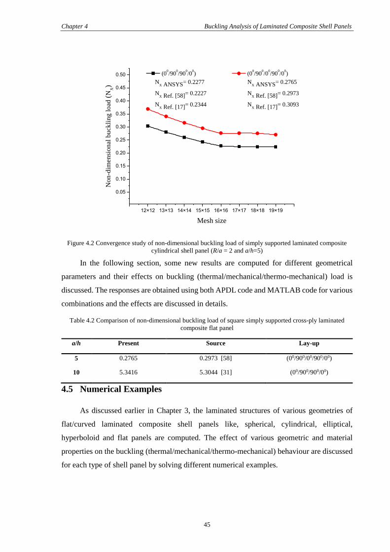
Chapter 4 Buckling Analysis of Laminated Composite Shell Panels
45
12×12 13×13 14×14 15×15 16×16 17×17 18×18 19×19
0.05
0.10
0.15
0.20
0.25
0.30
0.35
0.40
0.45
0.50
No
n-d
imen
sio
nal
bu
ckli
ng
lo
ad (
NX)
Mesh size
(00/90
0/90
0/0
0) (0
0/90
0/0
0/90
0/0
0)
NX ANSYS= 0.2277 N
X ANSYS= 0.2765
NX Ref. [58]= 0.2227 N
X Ref. [58]= 0.2973
NX Ref. [17]= 0.2344 N
X Ref. [17]= 0.3093
Figure 4.2 Convergence study of non-dimensional buckling load of simply supported laminated composite
cylindrical shell panel (R/a = 2 and a/h=5)
In the following section, some new results are computed for different geometrical
parameters and their effects on buckling (thermal/mechanical/thermo-mechanical) load is
discussed. The responses are obtained using both APDL code and MATLAB code for various
combinations and the effects are discussed in details.
Table 4.2 Comparison of non-dimensional buckling load of square simply supported cross-ply laminated
composite flat panel
a/h Present Source Lay-up
5 0.2765 0.2973 [58] (00/900/00/900/00)
10 5.3416 5.3044 [31] (00/900/900/00)
4.5 Numerical Examples
As discussed earlier in Chapter 3, the laminated structures of various geometries of
flat/curved laminated composite shell panels like, spherical, cylindrical, elliptical,
hyperboloid and flat panels are computed. The effect of various geometric and material
properties on the buckling (thermal/mechanical/thermo-mechanical) behaviour are discussed
for each type of shell panel by solving different numerical examples.
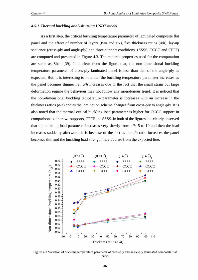
Chapter 4 Buckling Analysis of Laminated Composite Shell Panels
46
4.5.1 Thermal buckling analysis using HSDT model
As a first step, the critical buckling temperature parameter of laminated composite flat
panel and the effect of number of layers (two and six), five thickness ratios (a/h), lay-up
sequence (cross-ply and angle-ply) and three support conditions (SSSS, CCCC and CFFF)
are computed and presented in Figure 4.3. The material properties used for the computation
are same as Shen [39]. It is clear from the figure that, the non-dimensional buckling
temperature parameter of cross-ply laminated panel is less than that of the angle-ply as
expected. But, it is interesting to note that the buckling temperature parameter increases as
the panel becomes thinner i.e., a/h increases due to the fact that the small strain but large
deformation regime the behaviour may not follow any monotonous trend. It is noticed that
the non-dimensional buckling temperature parameter is increases with an increase in the
thickness ratios (a/h) and as the lamination scheme changes from cross-ply to angle-ply. It is
also noted that the thermal critical buckling load parameter is higher for CCCC support in
comparison to other two supports, CFFF and SSSS. In both of the figures it is clearly observed
that the buckling load parameter increases very slowly from a/h=5 to 10 and then the load
increases suddenly afterword. It is because of the fact as the a/h ratio increases the panel
becomes thin and the buckling load strength may deviate from the expected line.
-10 0 10 20 30 40 50 60 70 80 90 100 110
-0.02
0.00
0.02
0.04
0.06
0.08
0.10
0.12
0.14
0.16
0.18
0.20
0.22
0.24
0.26
0.28
0.30
0.32
0.34
No
n-d
imen
sio
nal
bu
ckli
ng
tem
per
atu
re (cr
)
Thickness ratio (a /h)
(00/90
0) (0
0/90
0)
3 (45
0) (45
0)
3
SSSS SSSS SSSS SSSS
CCCC CCCC CCCC CCCC
CFFF CFFF CFFF CFFF
Figure 4.3 Variation of buckling temperature parameter of cross-ply and angle-ply laminated composite flat
panel
Chapter 4 Buckling Analysis of Laminated Composite Shell Panels
47
Similarly, the critical buckling temperature parameter has been obtained for a square
cross-ply (00/900)3 and angle-ply (±150)3 laminated composite cylindrical panel for three
curvature ratios with two different support conditions (SSSS and CFFF). The buckling
responses are computed for six thickness ratios (a/h = 20, 30, 40, 50, 100 and 120) and three
curvature ratios (R/a = 5, 10 and 100) and presented in Table 4.3 using the material properties
as in Shen [39]. The table depicts that the buckling temperature parameter increases as the
curvature ratio increases and the angle-ply has higher thermal buckling strength in
comparison to cross-ply. It is observed that the buckling load parameter increases as the
curvature ratio and the thickness ratio increases for cross-ply laminations whereas the
buckling temperature decreases for angle-ply laminations as the a/h ratio increases. In
addition to above the thermal buckling load parameter is showing higher value for CFFF
support in comparison to SSSS support. It is also noted that angle-ply laminations are showing
higher thermal buckling load as compared to the cross-ply laminations hence, the angle-ply
laminates more are preferred for thermal shielding cases.
Table 4.3 Variation of buckling temperature parameter of cross-ply (00/900)3 and angle-ply (±150)3
laminated composite cylindrical panel
a/h
R/a 30 40 50 100 120
(00/900)3
SSSS
5 0.0268 0.0289 0.0295 0.034 0.0396
10 0.0271 0.0292 0.0298 0.0374 0.0651
100 0.0279 0.0299 0.0306 0.0497 0.1119
CFFF
5 0.0206 0.0288 0.0298 0.0305 0.0627
10 0.0265 0.029 0.03 0.0315 0.0419
100 0.0272 0.0304 0.0309 0.032 0.034
(±150)3
SSSS
5 0.9221 0.8517 0.8264 0.5421 0.2412
10 0.9277 0.8615 0.8628 0.6412 0.2452
100 0.9281 0.8652 0.8635 0.6822 0.5258
CFFF
5 0.875 0.8384 0.797 0.227 0.1528
10 0.8752 0.8463 0.8094 0.2288 0.1535
100 0.8758 0.847 0.8182 0.3764 0.1602
Now, in this section the thermal buckling strength of laminated angle-ply (±450)5
cylindrical panel has been studied using the developed mathematical model by varying five
thickness ratios (a/h = 5, 10, 20, 50 and 100) and two curvature ratios (R/a = 2 and 100). The
responses are obtained using the material properties same as Shen [39] and presented in Table
4.4. It is noticed from the table that, the critical buckling temperature parameter increases
with increase in the thickness ratio and decrease in the curvature ratio. The responses are not
following a monotonous trend and reverts from the expected line with the thickness ratio.
Chapter 4 Buckling Analysis of Laminated Composite Shell Panels
48
This is because of the fact that the thin structure may not follow a monotonous trend of results
due to severity in geometrical distortion.
Table 4.4 Non-dimensional buckling temperature of clamped square angle-ply (±450)5 laminated cylindrical
shell panel
a/h R/a
2 100
5 0.0376 0.0370
10 0.0351 0.0349
20 0.0503 0.0503
50 0.0876 0.0641
100 0.0871 0.0687
In addition to all the discussion made in above paragraphs the efficacy of the present
developed model is being analysed by conducting a comparative study of different geometries
such as spherical, elliptical and hyperboloid. The critical buckling temperature responses are
obtained by varying thickness ratios (a/h = 30 and 90) and curvature ratios (R/a = 50 and 100)
for SSSS, CCCC, SCSC and CFFF condition. The critical buckling temperature parameter
responses are obtained using the material properties same as Shen [39] and tabulated in the
Table 4.5. It is observed that the response are following the same trend as discussed for earlier
cases. It is observed that the buckling load parameter for hyperboloid panel is higher as
compared in other two geometries i.e., spherical and elliptical.
Table 4.5 Critical buckling temperature responses of cross-ply (00/900)5 laminated composite spherical,
hyperboloid and elliptical panel for different support condition
Geometry of the panel Support condition
R/a
50 100
a/h
30 90 30 90
Spherical
CCCC 0.0276 0.0296 0.0273 0.0544
SCSC 0.0273 0.0306 0.0273 0.0475
SSSS 0.024 0.0374 0.025 0.0452
CFFF 0.0261 0.0306 0.0244 0.041
Hyperboloid
CCCC 0.0282 0.0388 0.0057 0.0057
SCSC 0.0202 0.0347 0.0057 0.0057
SSSS 0.0258 0.0306 0.0253 0.0296
CFFF 0.0251 0.0297 0.0186 0.0392
Elliptical
CCCC 0.022 0.022 0.0179 0.0179
SCSC 0.022 0.022 0.0179 0.0187
SSSS 0.025 0.0268 0.0253 0.0261
CFFF 0.0247 0.027 0.0255 0.0512
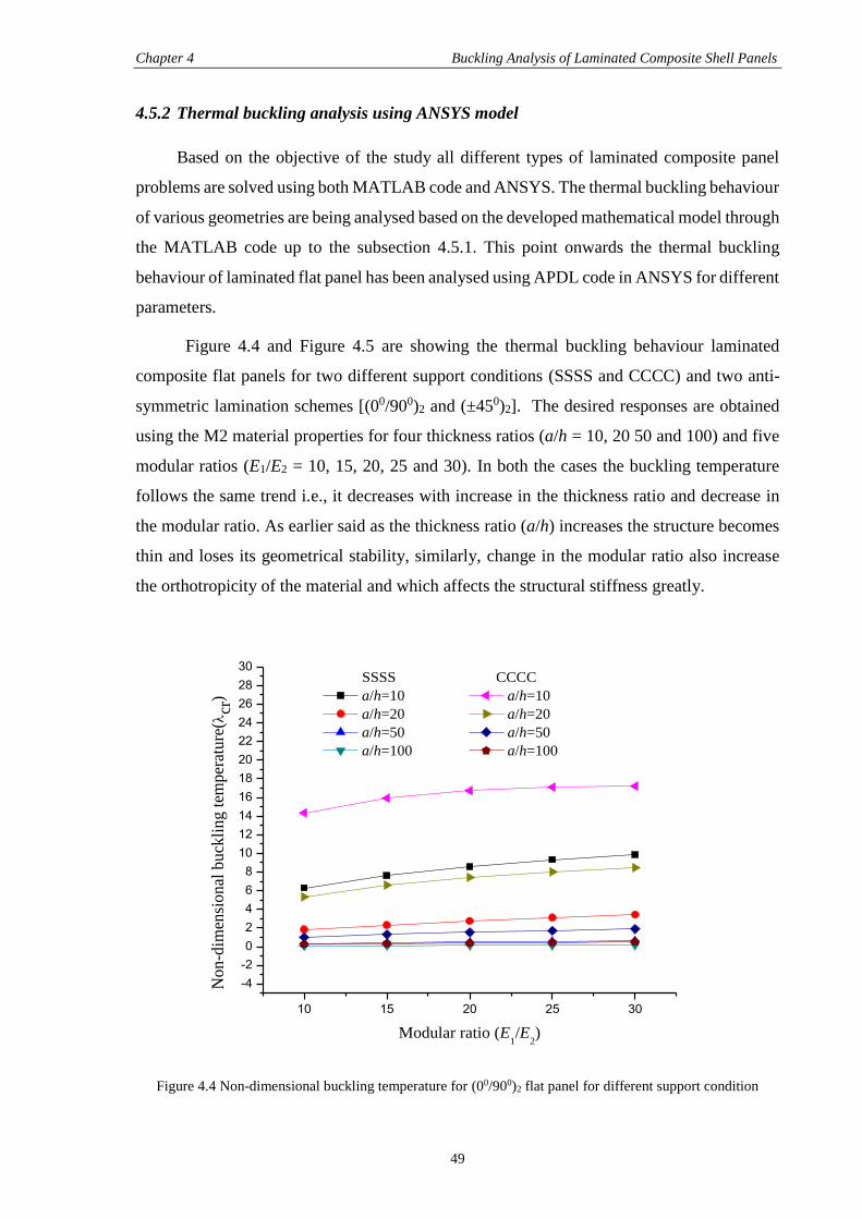
Chapter 4 Buckling Analysis of Laminated Composite Shell Panels
49
4.5.2 Thermal buckling analysis using ANSYS model
Based on the objective of the study all different types of laminated composite panel
problems are solved using both MATLAB code and ANSYS. The thermal buckling behaviour
of various geometries are being analysed based on the developed mathematical model through
the MATLAB code up to the subsection 4.5.1. This point onwards the thermal buckling
behaviour of laminated flat panel has been analysed using APDL code in ANSYS for different
parameters.
Figure 4.4 and Figure 4.5 are showing the thermal buckling behaviour laminated
composite flat panels for two different support conditions (SSSS and CCCC) and two anti-
symmetric lamination schemes [(00/900)2 and (±450)2]. The desired responses are obtained
using the M2 material properties for four thickness ratios (a/h = 10, 20 50 and 100) and five
modular ratios (E1/E2 = 10, 15, 20, 25 and 30). In both the cases the buckling temperature
follows the same trend i.e., it decreases with increase in the thickness ratio and decrease in
the modular ratio. As earlier said as the thickness ratio (a/h) increases the structure becomes
thin and loses its geometrical stability, similarly, change in the modular ratio also increase
the orthotropicity of the material and which affects the structural stiffness greatly.
10 15 20 25 30
-4
-2
0
2
4
6
8
10
12
14
16
18
20
22
24
26
28
30
No
n-d
imen
sio
nal
bu
ckli
ng
tem
per
atu
re(
cr)
Modular ratio (E1/E
2)
SSSS CCCC
a/h=10 a/h=10
a/h=20 a/h=20
a/h=50 a/h=50
a/h=100 a/h=100
Figure 4.4 Non-dimensional buckling temperature for (00/900)2 flat panel for different support condition
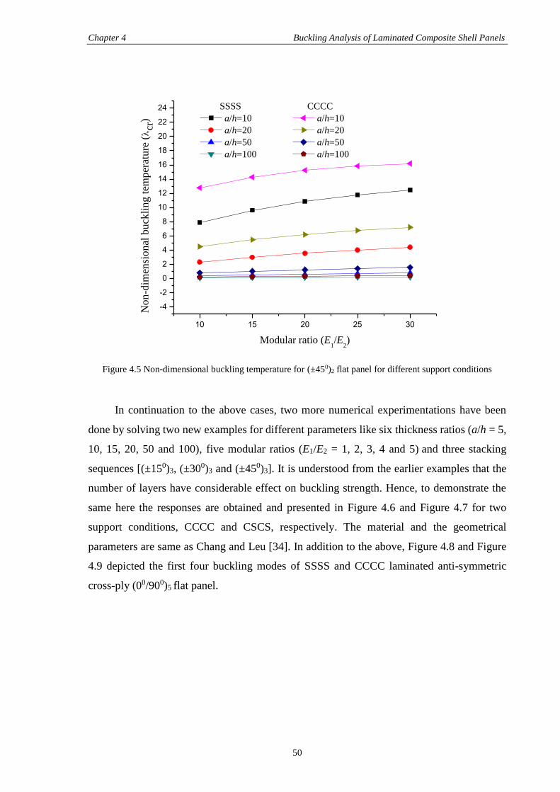
Chapter 4 Buckling Analysis of Laminated Composite Shell Panels
50
10 15 20 25 30
-4
-2
0
2
4
6
8
10
12
14
16
18
20
22
24
No
n-d
imen
sio
nal
bu
ckli
ng
tem
per
atu
re (cr
)
Modular ratio (E1/E
2)
SSSS CCCC
a/h=10 a/h=10
a/h=20 a/h=20
a/h=50 a/h=50
a/h=100 a/h=100
Figure 4.5 Non-dimensional buckling temperature for (±450)2 flat panel for different support conditions
In continuation to the above cases, two more numerical experimentations have been
done by solving two new examples for different parameters like six thickness ratios (a/h = 5,
10, 15, 20, 50 and 100), five modular ratios (E1/E2 = 1, 2, 3, 4 and 5) and three stacking
sequences [(±150)3, (±300)3 and (±450)3]. It is understood from the earlier examples that the
number of layers have considerable effect on buckling strength. Hence, to demonstrate the
same here the responses are obtained and presented in Figure 4.6 and Figure 4.7 for two
support conditions, CCCC and CSCS, respectively. The material and the geometrical
parameters are same as Chang and Leu [34]. In addition to the above, Figure 4.8 and Figure
4.9 depicted the first four buckling modes of SSSS and CCCC laminated anti-symmetric
cross-ply (00/900)5 flat panel.
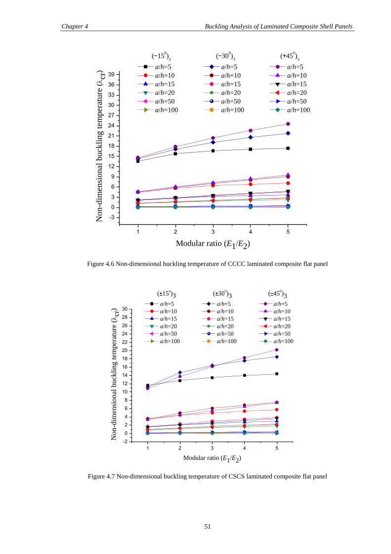
Chapter 4 Buckling Analysis of Laminated Composite Shell Panels
51
1 2 3 4 5
-3
0
3
6
9
12
15
18
21
24
27
30
33
36
39
No
n-d
imen
sio
nal
bu
ckli
ng
tem
per
atu
re (cr
)
Modular ratio (E1/E2)
( 150)
3 ( 30
0)
3 ( 45
0)
3
a/h=5 a/h=5 a/h=5
a/h=10 a/h=10 a/h=10
a/h=15 a/h=15 a/h=15
a/h=20 a/h=20 a/h=20
a/h=50 a/h=50 a/h=50
a/h=100 a/h=100 a/h=100
Figure 4.6 Non-dimensional buckling temperature of CCCC laminated composite flat panel
1 2 3 4 5
-2
0
2
4
6
8
10
12
14
16
18
20
22
24
26
28
30
No
n-d
imen
sio
nal
bu
ckli
ng
tem
per
atu
re (cr
)
Modular ratio (E1/E2)
( 150)3 ( 30
0)3 ( 45
0)3
a/h=5 a/h=5 a/h=5
a/h=10 a/h=10 a/h=10
a/h=15 a/h=15 a/h=15
a/h=20 a/h=20 a/h=20
a/h=50 a/h=50 a/h=50
a/h=100 a/h=100 a/h=100
Figure 4.7 Non-dimensional buckling temperature of CSCS laminated composite flat panel
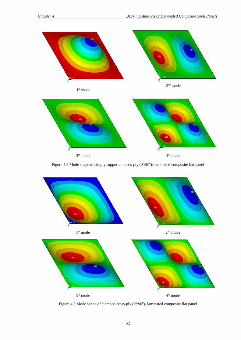
Chapter 4 Buckling Analysis of Laminated Composite Shell Panels
52
1st mode
2nd mode
3rd mode
4th mode
Figure 4.8 Mode shape of simply supported cross-ply (00/900)5 laminated composite flat panel
1st mode
2nd mode
3rd mode
4th mode
Figure 4.9 Mode shape of clamped cross-ply (00/900)5 laminated composite flat panel
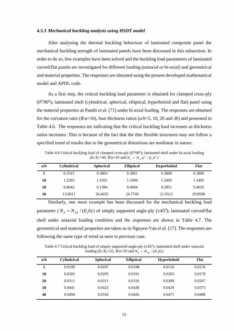
53
4.5.3 Mechanical buckling analysis using HSDT model
After analysing the thermal buckling behaviour of laminated composite panel the
mechanical buckling strength of laminated panels have been discussed in this subsection. In
order to do so, few examples have been solved and the buckling load parameters of laminated
curved/flat panels are investigated for different loading (uniaxial or bi-axial) and geometrical
and material properties. The responses are obtained using the present developed mathematical
model and APDL code.
As a first step, the critical buckling load parameter is obtained for clamped cross-ply
(00/900)5 laminated shell (cylindrical, spherical, elliptical, hyperboloid and flat) panel using
the material properties as Pandit et al. [71] under bi-axial loading. The responses are obtained
for the curvature ratio (R/a=10), four thickness ratios (a/h=5, 10, 20 and 30) and presented in
Table 4.6. The responses are indicating that the critical buckling load increases as thickness
ratios increases. This is because of the fact that the thin flexible structures may not follow a
specified trend of results due to the geometrical distortions are nonlinear in nature.
Table 4.6 Critical buckling load of clamped cross-ply (00/900)5 laminated shell under bi-axial loading
(E1/E2=40, R/a=10 and 2 3
2/
x xxN N a E h )
a/h Cylindrical Spherical Elliptical Hyperboloid Flat
5 0.3315 0.3803 0.3801 0.3800 0.3800
10 1.2303 1.5501 1.5494 1.5493 1.5495
20 6.8042 9.1384 9.4004 9.2851 9.4025
30 13.8011 26.4035 24.7749 21.6513 29.8590
Similarly, one more example has been discussed for the mechanical buckling load
parameter ( 2/ ( )X XXN N E h ) of simply supported angle-ply (±450)5 laminated curved/flat
shell under uniaxial loading condition and the responses are shown in Table 4.7. The
geometrical and material properties are taken as in Nguyen-Van et al. [17]. The responses are
following the same type of trend as seen in previous case.
Table 4.7 Critical buckling load of simply supported angle-ply (±450)5 laminated shell under uniaxial
loading (E1/E2=25, R/a=20 and2/ ( )X XXN N E h )
a/h Cylindrical Spherical Elliptical Hyperboloid Flat
5 0.0199 0.0187 0.0198 0.0116 0.0176
10 0.0203 0.0205 0.0191 0.0203 0.0178
20 0.0311 0.0311 0.0310 0.0309 0.0267
30 0.0441 0.0423 0.0438 0.0429 0.0373
40 0.0494 0.0318 0.0426 0.0471 0.0488
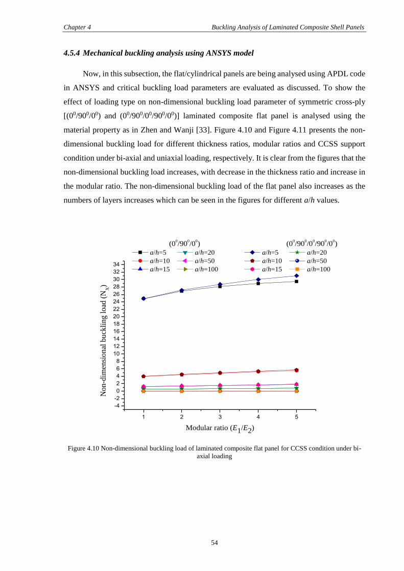
Chapter 4 Buckling Analysis of Laminated Composite Shell Panels
54
4.5.4 Mechanical buckling analysis using ANSYS model
Now, in this subsection, the flat/cylindrical panels are being analysed using APDL code
in ANSYS and critical buckling load parameters are evaluated as discussed. To show the
effect of loading type on non-dimensional buckling load parameter of symmetric cross-ply
[(00/900/00) and (00/900/00/900/00)] laminated composite flat panel is analysed using the
material property as in Zhen and Wanji [33]. Figure 4.10 and Figure 4.11 presents the non-
dimensional buckling load for different thickness ratios, modular ratios and CCSS support
condition under bi-axial and uniaxial loading, respectively. It is clear from the figures that the
non-dimensional buckling load increases, with decrease in the thickness ratio and increase in
the modular ratio. The non-dimensional buckling load of the flat panel also increases as the
numbers of layers increases which can be seen in the figures for different a/h values.
1 2 3 4 5
-4
-2
0
2
4
6
8
10
12
14
16
18
20
22
24
26
28
30
32
34
No
n-d
imen
sio
nal
bu
ckli
ng
lo
ad (
NX)
Modular ratio (E1/E2)
(00/90
0/0
0) (0
0/90
0/0
0/90
0/0
0)
a/h=5 a/h=20 a/h=5 a/h=20
a/h=10 a/h=50 a/h=10 a/h=50
a/h=15 a/h=100 a/h=15 a/h=100
Figure 4.10 Non-dimensional buckling load of laminated composite flat panel for CCSS condition under bi-
axial loading
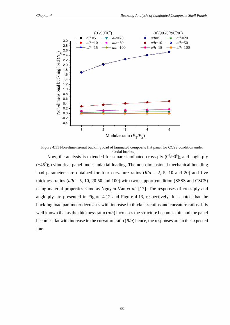
Chapter 4 Buckling Analysis of Laminated Composite Shell Panels
55
1 2 3 4 5
-0.4
-0.2
0.0
0.2
0.4
0.6
0.8
1.0
1.2
1.4
1.6
1.8
2.0
2.2
2.4
2.6
2.8
3.0
No
n-d
imen
sio
nal
bu
ckli
ng
lo
ad (
NX)
Modular ratio (E1/E2)
(00/90
0/0
0) (0
0/90
0/0
0/90
0/0
0)
a/h=5 a/h=20 a/h=5 a/h=20
a/h=10 a/h=50 a/h=10 a/h=50
a/h=15 a/h=100 a/h=15 a/h=100
Figure 4.11 Non-dimensional buckling load of laminated composite flat panel for CCSS condition under
uniaxial loading
Now, the analysis is extended for square laminated cross-ply (00/900)2 and angle-ply
(±450)2 cylindrical panel under uniaxial loading. The non-dimensional mechanical buckling
load parameters are obtained for four curvature ratios (R/a = 2, 5, 10 and 20) and five
thickness ratios (a/h = 5, 10, 20 50 and 100) with two support condition (SSSS and CSCS)
using material properties same as Nguyen-Van et al. [17]. The responses of cross-ply and
angle-ply are presented in Figure 4.12 and Figure 4.13, respectively. It is noted that the
buckling load parameter decreases with increase in thickness ratios and curvature ratios. It is
well known that as the thickness ratio (a/h) increases the structure becomes thin and the panel
becomes flat with increase in the curvature ratio (R/a) hence, the responses are in the expected
line.
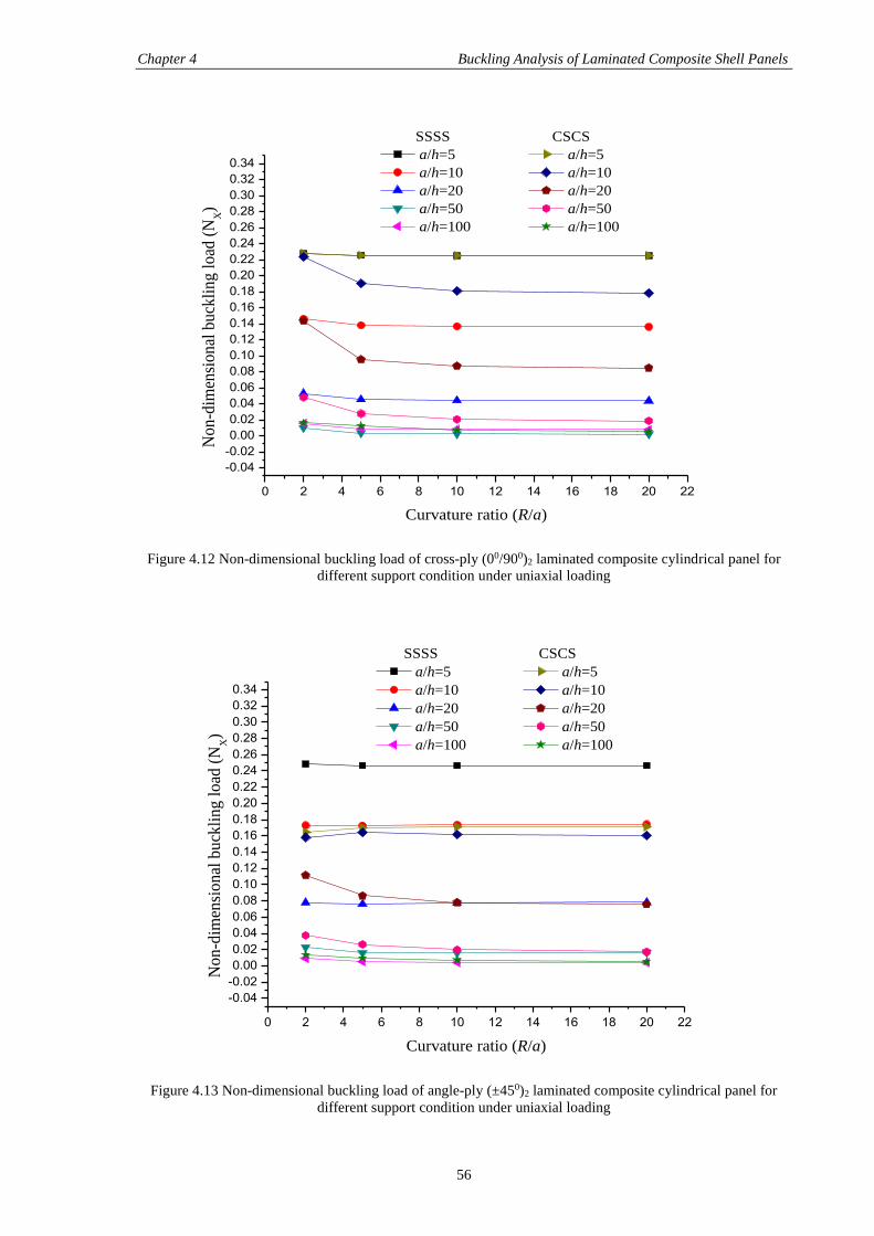
Chapter 4 Buckling Analysis of Laminated Composite Shell Panels
56
0 2 4 6 8 10 12 14 16 18 20 22
-0.04
-0.02
0.00
0.02
0.04
0.06
0.08
0.10
0.12
0.14
0.16
0.18
0.20
0.22
0.24
0.26
0.28
0.30
0.32
0.34
No
n-d
imen
sio
nal
bu
ckli
ng
lo
ad (
NX)
Curvature ratio (R/a)
SSSS CSCS
a/h=5 a/h=5
a/h=10 a/h=10
a/h=20 a/h=20
a/h=50 a/h=50
a/h=100 a/h=100
Figure 4.12 Non-dimensional buckling load of cross-ply (00/900)2 laminated composite cylindrical panel for
different support condition under uniaxial loading
0 2 4 6 8 10 12 14 16 18 20 22
-0.04
-0.02
0.00
0.02
0.04
0.06
0.08
0.10
0.12
0.14
0.16
0.18
0.20
0.22
0.24
0.26
0.28
0.30
0.32
0.34
No
n-d
imen
sio
nal
bu
ckli
ng
lo
ad (
NX)
Curvature ratio (R/a)
SSSS CSCS
a/h=5 a/h=5
a/h=10 a/h=10
a/h=20 a/h=20
a/h=50 a/h=50
a/h=100 a/h=100
Figure 4.13 Non-dimensional buckling load of angle-ply (±450)2 laminated composite cylindrical panel for
different support condition under uniaxial loading
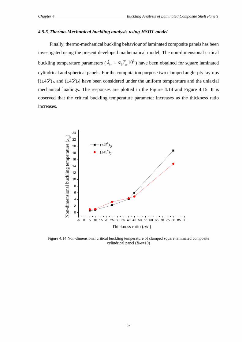
Chapter 4 Buckling Analysis of Laminated Composite Shell Panels
57
4.5.5 Thermo-Mechanical buckling analysis using HSDT model
Finally, thermo-mechanical buckling behaviour of laminated composite panels has been
investigated using the present developed mathematical model. The non-dimensional critical
buckling temperature parameters (3
0 10cr crT ) have been obtained for square laminated
cylindrical and spherical panels. For the computation purpose two clamped angle-ply lay-ups
[(±450) S and (±450)2] have been considered under the uniform temperature and the uniaxial
mechanical loadings. The responses are plotted in the Figure 4.14 and Figure 4.15. It is
observed that the critical buckling temperature parameter increases as the thickness ratio
increases.
-5 0 5 10 15 20 25 30 35 40 45 50 55 60 65 70 75 80 85 90
0
2
4
6
8
10
12
14
16
18
20
22
24
No
n-d
imen
sio
nal
bu
ckli
ng
tem
per
atu
re (
cr)
Thickness ratio (a/h)
(±450)S
(±450)2
Figure 4.14 Non-dimensional critical buckling temperature of clamped square laminated composite
cylindrical panel (R/a=10)
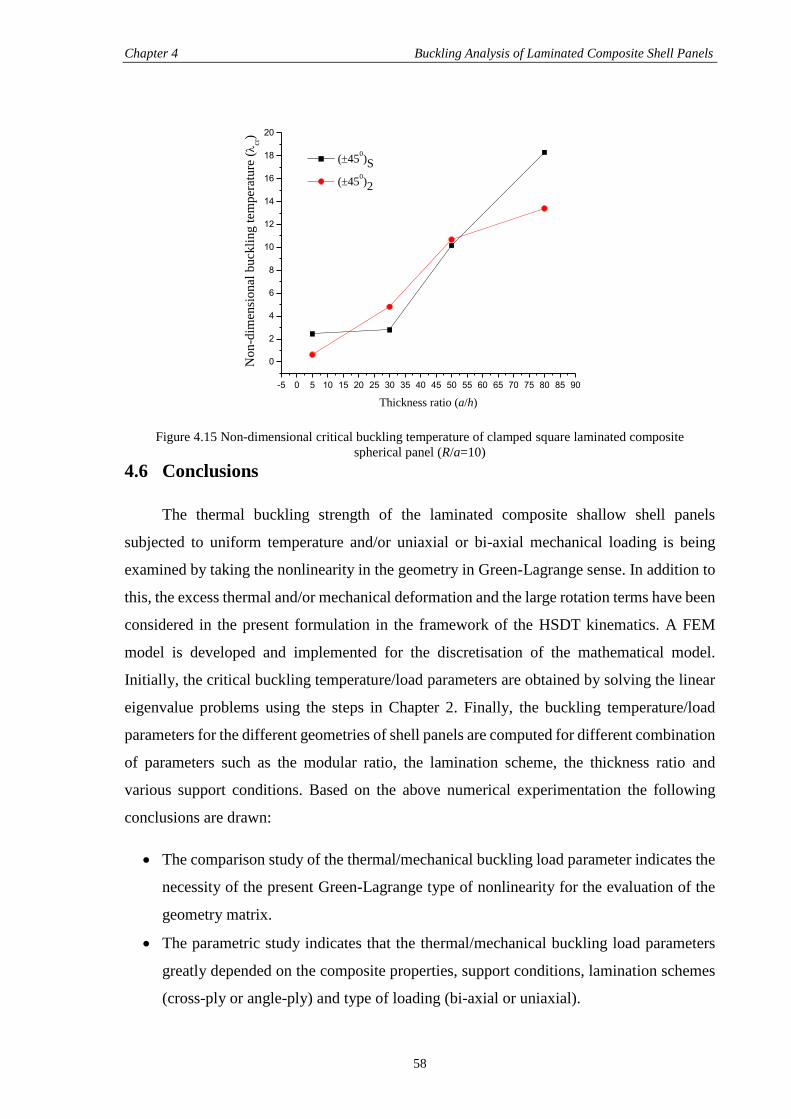
Chapter 4 Buckling Analysis of Laminated Composite Shell Panels
58
-5 0 5 10 15 20 25 30 35 40 45 50 55 60 65 70 75 80 85 90
0
2
4
6
8
10
12
14
16
18
20
No
n-d
imen
sio
nal
bu
ckli
ng
tem
per
atu
re (
cr)
Thickness ratio (a/h)
(450)S
(450)2
Figure 4.15 Non-dimensional critical buckling temperature of clamped square laminated composite
spherical panel (R/a=10)
4.6 Conclusions
The thermal buckling strength of the laminated composite shallow shell panels
subjected to uniform temperature and/or uniaxial or bi-axial mechanical loading is being
examined by taking the nonlinearity in the geometry in Green-Lagrange sense. In addition to
this, the excess thermal and/or mechanical deformation and the large rotation terms have been
considered in the present formulation in the framework of the HSDT kinematics. A FEM
model is developed and implemented for the discretisation of the mathematical model.
Initially, the critical buckling temperature/load parameters are obtained by solving the linear
eigenvalue problems using the steps in Chapter 2. Finally, the buckling temperature/load
parameters for the different geometries of shell panels are computed for different combination
of parameters such as the modular ratio, the lamination scheme, the thickness ratio and
various support conditions. Based on the above numerical experimentation the following
conclusions are drawn:
The comparison study of the thermal/mechanical buckling load parameter indicates the
necessity of the present Green-Lagrange type of nonlinearity for the evaluation of the
geometry matrix.
The parametric study indicates that the thermal/mechanical buckling load parameters
greatly depended on the composite properties, support conditions, lamination schemes
(cross-ply or angle-ply) and type of loading (bi-axial or uniaxial).
Chapter 4 Buckling Analysis of Laminated Composite Shell Panels
59
The thermal/mechanical buckling load parameters increases with increase in the
modular ratio with all types of support condition.
The critical buckling temperature parameter is higher for angle-ply laminates in
comparison to cross-ply laminates.
Increase in the lay-up scheme has also significant effect on the critical buckling
temperature parameters and it is noted that the temperature increases with increase in
the number of layers.
It is also interesting to note that in some of the cases of the thickness ratio the desired
responses are reverted from their expected line. This is because of the fact that the thin
structure may not follow a monotonous trend as expected for small strain and large
(finite) deformation regime.
From the study, it is understood that there is an importance of large rotation and
deformation terms to consider in the mathematical model for highly flexible structures.
In addition to that the geometric alternations especially laminated structures are need to
be modelled using Green-Lagrange type of nonlinearity in the framework of the HSDT.
60
CHAPTER 5
CLOSURE
5.1 Concluding Remarks
Free vibration and buckling (thermal/mechanical/thermo-mechanical) behaviour of
laminated composite single/doubly curved panels are computed using higher order mid-plane
kinematics. The geometry matrix associated in buckling is evaluated using Green-Lagrange
strain displacement relations to evaluate the excess thermal and/or mechanical deformation
of laminated panel. A linear finite element is proposed and implemented to discretise the
domain and solved numerically to obtain the desired responses by using a nine noded
isoparametric Lagrangian element having ten degrees of freedom per node. The non-
dimensional fundamental frequency and critical buckling load parameters are obtained
solving the linear eigenvalue problem. The more specific conclusions as a result of the present
investigation are stated below:
In this present analysis Green-Lagrange type strain displacement relation is considered
for the evaluation of geometric stiffness matrix for buckling analysis. The geometrical
nonlinearity arising in the curved panel due to excess in-plane deformation have been
considered to account the exact panel flexure. It is understood that the geometric
nonlinearity modelled in von-Karman sense based on the FSDT and/or the HSDT is
unrealistic in nature for the structures having severe geometric alteration.
The system governing equations are derived by minimising the total potential energy
and solved to obtain the desired responses. The model has been validated by comparing
the responses with those published literature and comprehensiveness of the model is
shown by solving different examples through the developed model. In addition to that
the results are also computed in ANSYS using APDL code.
The effect of various panel geometries (cylindrical, spherical, elliptical, hyperboloid
and flat) and other parameters (thickness ratios, curvature ratios, aspect ratios, modular
ratios, lay-up schemes and support conditions) on the free vibration behaviour are
computed for without temperature effect. It is noted that the thickness ratio, the
curvature ratio, the modular ratio, the aspect ratio and the edge support conditions are
seen to affect the non-dimensional fundamental frequency parameter considerably.
Closure
61
The non-dimensional fundamental frequency parameter increases with increase in the
thickness ratio, the modular ratio and the number of layers, whereas it decreases with
increase in the curvature ratio. The frequencies are not following same type of trend for
lamination scheme and support conditions.
The buckling (thermal/mechanical/thermo-mechanical) strength of laminated
composite cylindrical, spherical, elliptical, hyperboloid and flat panels have been
examined by taking the uniform temperature field throughout the thickness.
Effect of the thickness ratios, the curvature ratios, the modular ratios, the lay-up
schemes, the loading types (uniaxial/bi-axial) and the support conditions are studied in
detail. It is observed that the non-dimensional critical buckling temperature parameter
of angle-ply lamination are showing higher critical buckling temperature in comparison
to the cross-ply laminations.
The non-dimensional buckling load/parameter increases with increase in the modular
ratio, the number of layers and the thickness ratio but it is important to mention that in
some of the cases the responses are following a reverse trend for the small strain and
large deformations. The responses are decreases with increase in the curvature ratio and
non-monotonic behaviour is noted for the support conditions and the lay-up schemes.
5.2 Significant Contribution of the Thesis
The contributions of the present research work are as follows:
A general mathematical model of curved panel has been developed in the framework
of the HSDT mid-plane kinematics by taking all the higher order terms in the
mathematical formulation for more accurate prediction of vibration and buckling
(thermal/mechanical/thermo-mechanical) behaviour of laminated composite panels.
In buckling case, Green-Lagrange type strain displacement relation is considered to take
into account the geometrical nonlinearity arising in the curved panel due to excess
thermal and/or mechanical deformation for evaluation of geometry stiffness matrix.
Further, the panel model has been developed in the commercial FE software ANSYS
using APDL code. Different numerical examples have been considered to show the
efficacy of the developed mathematical and simulation model. The convergence and
comparison study for free vibration and buckling behaviour of laminated panel is
presented.
A finite element method is employed for the discretisation purpose by using a nine
noded isoparametric Lagrangian element with ten DOFs per node. In addition to this,
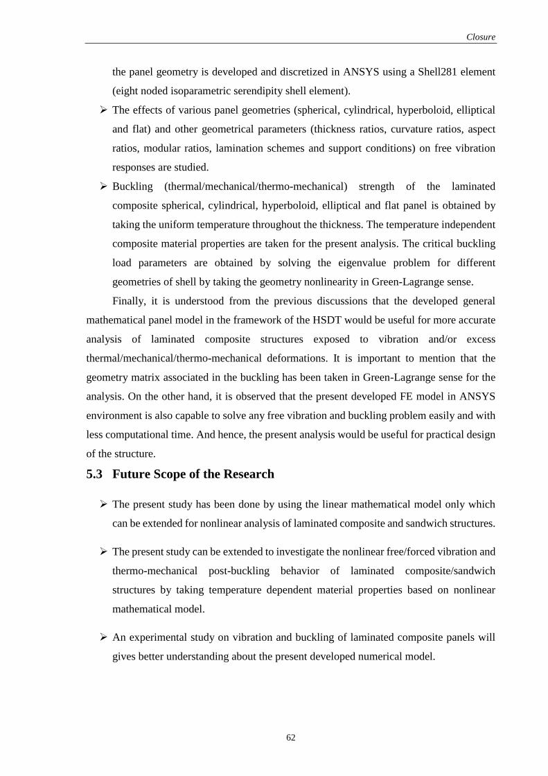
Closure
62
the panel geometry is developed and discretized in ANSYS using a Shell281 element
(eight noded isoparametric serendipity shell element).
The effects of various panel geometries (spherical, cylindrical, hyperboloid, elliptical
and flat) and other geometrical parameters (thickness ratios, curvature ratios, aspect
ratios, modular ratios, lamination schemes and support conditions) on free vibration
responses are studied.
Buckling (thermal/mechanical/thermo-mechanical) strength of the laminated
composite spherical, cylindrical, hyperboloid, elliptical and flat panel is obtained by
taking the uniform temperature throughout the thickness. The temperature independent
composite material properties are taken for the present analysis. The critical buckling
load parameters are obtained by solving the eigenvalue problem for different
geometries of shell by taking the geometry nonlinearity in Green-Lagrange sense.
Finally, it is understood from the previous discussions that the developed general
mathematical panel model in the framework of the HSDT would be useful for more accurate
analysis of laminated composite structures exposed to vibration and/or excess
thermal/mechanical/thermo-mechanical deformations. It is important to mention that the
geometry matrix associated in the buckling has been taken in Green-Lagrange sense for the
analysis. On the other hand, it is observed that the present developed FE model in ANSYS
environment is also capable to solve any free vibration and buckling problem easily and with
less computational time. And hence, the present analysis would be useful for practical design
of the structure.
5.3 Future Scope of the Research
The present study has been done by using the linear mathematical model only which
can be extended for nonlinear analysis of laminated composite and sandwich structures.
The present study can be extended to investigate the nonlinear free/forced vibration and
thermo-mechanical post-buckling behavior of laminated composite/sandwich
structures by taking temperature dependent material properties based on nonlinear
mathematical model.
An experimental study on vibration and buckling of laminated composite panels will
gives better understanding about the present developed numerical model.

Closure
63
By extending the present model, a nonlinear mathematical model can be developed to
study the behaviour of laminated composite and sandwich structures in thermal and/or
hygro-thermal environment.
The smart (piezo, shape memory alloys and magnetostrictive) materials can be
incorporated in the nonlinear model to study the effects of material and geometrical
parameters.
It will be interesting to study the flutter characteristics considering the aerodynamic and
acoustic loading that arises frequently in the practical cases.
64
REFERENCES
[1] T. Kant and K. Swaminathan, “Analytical solutions for free vibration of laminated
composite and sandwich plates based on a higher order refined theory,” Compos.
Struct., vol. 53, pp. 73–85, 2001.
[2] H. Matsunaga, “Free vibration and stability of angle-ply laminated composite and
sandwich plates under thermal loading,” Compos. Struct., vol. 77, no. 2, pp. 249–262,
Jan. 2007.
[3] H. Matsunaga, “Vibration of cross-ply laminated composite plates subjected to initial
in-plane stresses,” Thin-Walled Struct., vol. 40, no. 7–8, pp. 557–571, Jan. 2002.
[4] N. S. Putcha and J. N. Reddy, “Stability and natural vibration analysis of laminated
plates by using a mixed element based on a refined plate theory,” Journal of Sound and
Vibration, pp. 285-300, 1986.
[5] J. N. Reddy and C. F. Liu, “A higher order shear deformation theory of laminated elastic
shells,” Int. J. of Eng. Sci., vol. 23, pp. 319–30, 1985.
[6] A. J. M. Ferreira, C. M. C. Roque, A. M. A. Neves, R. M. N. Jorge, C. M. M. Soares,
and K. M. Liew, “Buckling and vibration analysis of isotropic and laminated plates by
radial basis functions,” Compos. Part B Eng., vol. 42, no. 3, pp. 592–606, Apr. 2011.
[7] A. Bhar, S. S. Phoenix, and S. K. Satsangi, “Finite element analysis of laminated
composite stiffened plates using FSDT and HSDT: A comparative perspective,”
Compos. Struct., vol. 92, no. 2, pp. 312–321, Jan. 2010.
[8] J. L. Mantari, A. S. Oktem, and C. Guedes Soares, “Static and dynamic analysis of
laminated composite and sandwich plates and shells by using a new higher order shear
deformation theory,” Compos. Struct., vol. 94, no. 1, pp. 37–49, Dec. 2011.
[9] S. Xiang and G. W. Kang, “Local thin plate spline collocation for free vibration analysis
of laminated composite plates,” European J. of Mecha. A/Solids, vol. 33, pp. 24-30,
2012.
[10] S. Xiang, Z. Y. Bi, S. X. Jiang, Y. X. Jin and M. S. Yang, “Thin plate spline radial basis
function for the free vibration analysis of laminated composite shells,” Compo. Struct.,
vol. 93, pp. 611–615, 2011.
[11] X. Y. Cui, G. R. Liu and G. Y. Li, “Bending and vibration responses of laminated
composite plates using an edge-based smoothing technique,” Engineering Analysis with
Boundary Elements, vol. 35, pp. 818–826, 2011.
References
65
[12] S. Hatami, M. Azahari and M. M. Sadatpour, “Free vibration of moving laminated
composite plates,” Compo. Struct., vol. 80, pp. 609-620, 2007.
[13] E. Viola, F. Tornabene, and N. Fantuzzi, “General higher order shear deformation
theories for the free vibration analysis of completely doubly-curved laminated shells
and panels,” Compos. Struct., vol. 95, pp. 639–666, Jan. 2013.
[14] F. Tornabene, E. Viola, and N. Fantuzzi, “General higher order equivalent single layer
theory for free vibrations of doubly-curved laminated composite shells and panels,”
Compos. Struct., vol. 104, pp. 94–117, Oct. 2013.
[15] G. Jin, T. Ye, X. Jia, and S. Gao, “A general Fourier solution for the vibration analysis
of composite laminated structure elements of revolution with general elastic restraints,”
Compos. Struct., vol. 109, pp. 150–168, Mar. 2014.
[16] G. Jin, T. Ye, Y. Chen, Z. Su, and Y. Yan, “An exact solution for the free vibration
analysis of laminated composite cylindrical shells with general elastic boundary
conditions,” Compos. Struct., vol. 106, pp. 114–127, Dec. 2013.
[17] H. Nguyen-Van, N. Mai-Duy, W. Karunasena, and T. Tran-Cong, “Buckling and
vibration analysis of laminated composite plate/shell structures via a smoothed
quadrilateral flat shell element with in-plane rotations,” Comput. Struct., vol. 89, no. 7–
8, pp. 612–625, Apr. 2011.
[18] H.-T. Thai and S.-E. Kim, “Free vibration of laminated composite plates using two
variable refined plate theory,” Int. J. Mech. Sci., vol. 52, no. 4, pp. 626–633, Apr. 2010.
[19] A. Kumar, A. Chakrabarti, and P. Bhargava, “Finite element analysis of laminated
composite and sandwich shells using higher order zigzag theory,” Compos. Struct., vol.
106, pp. 270–281, Dec. 2013.
[20] L. Dozio, “In-plane free vibrations of single-layer and symmetrically laminated
rectangular composite plates,” Compos. Struct., vol. 93, no. 7, pp. 1787–1800, Jun.
2011.
[21] D. Ngo-Cong, N. Mai-Duy, W. Karunasena, and T. Tran-Cong, “Free vibration analysis
of laminated composite plates based on FSDT using one-dimensional IRBFN method,”
Comput. Struct., vol. 89, no. 1–2, pp. 1–13, Jan. 2011.
[22] P. Patel, K. Khan, and Y. Nath, “A new constitutive model for free vibration analysis
of bimodular composite laminated cylindrical/conical panels,” Compos. Struct., Nov.
2013.
References
66
[23] S. M. R. Khalili, M. Shariyat, and I. Rajabi, “A finite element based global–local theory
for static analysis of rectangular sandwich and laminated composite plates,” Compos.
Struct., vol. 107, pp. 177–189, Jan. 2014.
[24] T. M. Tu, L. N. Thach, and T. H. Quoc, “Finite element modeling for bending and
vibration analysis of laminated and sandwich composite plates based on higher order
theory,” Comput. Mater. Sci., vol. 49, no. 4, pp. S390–S394, Oct. 2010.
[25] T. Ye, G. Jin, Y. Chen, X. Ma, and Z. Su, “Free vibration analysis of laminated
composite shallow shells with general elastic boundaries,” Compos. Struct., vol. 106,
pp. 470–490, Dec. 2013.
[26] W. Zhen, C. Wanji, and R. Xiaohui, “An accurate higher order theory and C0 finite
element for free vibration analysis of laminated composite and sandwich plates,”
Compos. Struct., vol. 92, no. 6, pp. 1299–1307, May 2010.
[27] X. Xie, G. Jin, Y. Yan, S. X. Shi, and Z. Liu, “Free vibration analysis of composite
laminated cylindrical shells using the Haar wavelet method,” Compos. Struct., vol. 109,
pp. 169–177, Mar. 2014.
[28] Y. Qu, X. Long, S. Wu, and G. Meng, “A unified formulation for vibration analysis of
composite laminated shells of revolution including shear deformation and rotary
inertia,” Compos. Struct., vol. 98, pp. 169–191, Apr. 2013.
[29] M. E. Fares and A. M. Zenkour, “Buckling and free vibration of non-homogeneous
composite cross-ply laminated plates with various plate theories”, Composite
structures, vol. 44, pp. 279–287, 1999.
[30] T. Kant and Mallikarjuna, A higher order theory for free vibration of unsymmetrically
laminated composite and sandwich plates finite element evaluations, Compu. and
Struct., vol. 32, pp. 1125-1132, 1989.
[31] A. K. Noor, “Free vibrations of multilayered composite plates,” AIAA J, vol. 11, no. 7,
pp. 1038–39, 1972.
[32] A. K. Noor, “Stability of multilayered composite plates,” Fiber Sci Techno., vol. 8, no.
2, pp. 1038–39, 1975.
[33] W. Zhen and C. Wanji, “Thermomechanical buckling of laminated composite and
sandwich plates using global–local higher order theory,” Int. J. Mech. Sci., vol. 49, no.
6, pp. 712–721, Jun. 2007.
[34] J. S. Chang and S.Y. Leu, “Thermal buckling analysis of antisymmetric angle-ply
laminates based on a higher order displacement field,” Compos. Sci. and Tech., vol. 41,
pp. 109-128, 1991.
References
67
[35] K. K. Shukla and Y. Nath, “Analytical solution for buckling and post-buckling of angle-
ply laminated plates under thermo-mechanical loading,” Int. J. of Non-Linear
Mechanics, vol. 36, pp. 1097-1108, 2001.
[36] J. Lee, “Thermally-induced buckling of laminated composites by a layerwise theory,”
Comput. & Struct., vol. 65, no. 6, pp. 917-922, 1997.
[37] A. H. Sofiyev and N. Kuruoglu, “The non-linear buckling analysis of cross-ply
laminated orthotropic truncated conical shells,” Compos. Struct., vol. 93, no. 11, pp.
3006–3012, Oct. 2011.
[38] R. Vosoughi, P. Malekzadeh, M. R. Banan, and M. R. Banan, “Thermal buckling and
postbuckling of laminated composite beams with temperature-dependent properties,”
Int. J. Non. Linear. Mech., vol. 47, no. 3, pp. 96–102, Apr. 2012.
[39] H. S. Shen, “Thermal post-buckling analysis of imperfect laminated plates using a
higher order shear deformation theory,” Int. J. Non. Linear. Mech., vol. 32, no. 6, pp.
1035–1050, Nov. 1997.
[40] A. N. Jameel, I. A. Sadiq and H. I. Nsaif, “Buckling Analysis of Composite Plates under
Thermal and Mechanical Loading,” Journal of Engineering, vol. 18, pp. 1365–1390,
Dec. 2012.
[41] D. Li, G. Qing, and Y. Liu, “A layerwise/solid-element method for the composite
stiffened laminated cylindrical shell structures,” Compos. Struct., vol. 98, pp. 215–227,
Apr. 2013.
[42] F. A. Fazzolari, J. R. Banerjee, and M. Boscolo, “Buckling of composite plate
assemblies using higher order shear deformation theory—An exact method of
solution,” Thin-Walled Struct., vol. 71, pp. 18–34, Oct. 2013.
[43] F. Shadmehri, S. V. Hoa, and M. Hojjati, “Buckling of conical composite shells,”
Compos. Struct., vol. 94, no. 2, pp. 787–792, Jan. 2012.
[44] H. Farahmand, A. R. Ahmadi, and S. Arabnejad, “Thermal buckling analysis of
rectangular microplates using higher continuity p-version finite element method,” Thin-
Walled Struct., vol. 49, no. 12, pp. 1584–1591, Dec. 2011.
[45] L.-C. Shiau, S.-Y. Kuo, and C.-Y. Chen, “Thermal buckling behavior of composite
laminated plates,” Compos. Struct., vol. 92, no. 2, pp. 508–514, Jan. 2010.
[46] M. M. Kheirikhah, S. M. R. Khalili, and K. Malekzadeh Fard, “Biaxial buckling
analysis of soft-core composite sandwich plates using improved high-order theory,”
Eur. J. Mech. - A/Solids, vol. 31, no. 1, pp. 54–66, Jan. 2012.
References
68
[47] P. Nali, E. Carrera, and S. Lecca, “Assessments of refined theories for buckling analysis
of laminated plates,” Compos. Struct., vol. 93, no. 2, pp. 456–464, Jan. 2011.
[48] T. Kant and C. S. Babu, “Refined higher order finite element models for thermal
buckling of laminated composite and sandwich plates,” J. of Thermal Stress, vol. 23,
pp. 111-130, 2000.
[49] T. Kant and C. S. Babu, “Thermal buckling analysis of skew fibre-reinforced composite
and sandwich plates using shear deformable finite element models” Compo. Struct.,
vol. 49, pp. 77-85, 2000.
[50] S. K. Panda and B. N. Singh, “Thermal post-buckling behaviour of laminated composite
cylindrical/hyperboloidal shallow shell panel using nonlinear finite element method,”
Compo. Struct., vol. 91, no. 3, pp. 366-384, 2009.
[51] S. Singh, J. Singh, and K. K. Shukla, “Buckling of laminated composite plates subjected
to mechanical and thermal loads using meshless collocations,” J. Mech. Sci. Technol.,
vol. 27, no. 2, pp. 327–336, Mar. 2013.
[52] N. Grover, D. K. Maiti and B. N. Singh, “A new inverse hyperbolic shear deformation
theory for static and buckling analysis of laminated composite and sandwich plates,”
Compos. Struct., vol. 95, pp. 667–675, Jan.2013.
[53] W. Zhen and C. Wanji, “Buckling analysis of angle-ply composite and sandwich plates
by combination of geometric stiffness matrix,” Comput. Mech., vol. 39, pp. 839–848,
Apr. 2006.
[54] U. Topal and U. Uzman, “Optimum design of laminated composite plates to maximize
buckling load using MFD method,” Thin-Walled Struct., vol. 45, pp. 660–669, Jul.
2007.
[55] A. A. Khdeir and L. Librescu, “Analysis of symmetric cross-ply laminated elastic plates
using a higher order theory: Part II—Buckling and free vibration,” Compos. Struct.,
vol. 9, no. 4, pp. 259–277, Jan. 1988.
[56] F. A. Fazzolari, J. R. Banerjee, and M. Boscolo, “Buckling of composite plate
assemblies using higher order shear deformation theory—An exact method of
solution,” Thin-Walled Struct., vol. 71, pp. 18–34, Oct. 2013.
[57] H. Akbulut, O. Gundogdu, and M. Şengul, “Buckling behaviors of laminated composite
stepped flat columns,” Finite Elem. Anal. Des., vol. 46, no. 12, pp. 1061–1067, Dec.
2010.
[58] H. Matsunaga, “Vibration and stability of cross-ply laminated composite shallow shells
subjected to in-plane stresses,” Compos. Struct., vol. 78, no. 3, pp. 377–391, May 2007.
References
69
[59] A. J. M. Ferreira, C. M. C. Roque, A. M. A. Neves, R. M. N. Jorge, C. M. M. Soares,
and J. N. Reddy, “Buckling analysis of isotropic and laminated plates by radial basis
functions according to a higher order shear deformation theory,” Thin-Walled Struct.,
vol. 49, no. 7, pp. 804–811, Jul. 2011.
[60] A. Lal, B. N. Singh, and S. Kale, “Stochastic post buckling analysis of laminated
composite cylindrical shell panel subjected to hygrothermomechanical loading,”
Compos. Struct., vol. 93, no. 4, pp. 1187–1200, Mar. 2011.
[61] C. Amadio and C. Bedon, “Buckling of laminated glass elements in out-of-plane
bending,” Eng. Struct., vol. 32, no. 11, pp. 3780–3788, Nov. 2010.
[62] C. Bedon and C. Amadio, “Buckling of flat laminated glass panels under in-plane
compression or shear,” Eng. Struct., vol. 36, pp. 185–197, Mar. 2012.
[63] I. Chirica and E.-F. Beznea, “Buckling behavior of the multiple delaminated composite
plates under shear and axial compression,” Comput. Mater. Sci., vol. 64, pp. 173–178,
Nov. 2012.
[64] J. Abediokhchi, M. A. Kouchakzadeh, and M. Shakouri, “Buckling analysis of cross-
ply laminated conical panels using GDQ method,” Compos. Part B Eng., vol. 55, pp.
440–446, Dec. 2013.
[65] M. Aydin Komur, F. Sen, A. Ataş, and N. Arslan, “Buckling analysis of laminated
composite plates with an elliptical/circular cutout using FEM,” Adv. Eng. Softw., vol.
41, no. 2, pp. 161–164, Feb. 2010.
[66] P. Dash and B. N. Singh, “Buckling and post-buckling of laminated composite plates,”
Mech. Res. Commun., vol. 46, pp. 1–7, Dec. 2012.
[67] R. Seifi, N. Khoda-yari, and H. Hosseini, “Study of critical buckling loads and modes
of cross-ply laminated annular plates,” Compos. Part B Eng., vol. 43, no. 2, pp. 422–
430, Mar. 2012.
[68] S. M. R. Khalili, P. Abbaspour, and K. Malekzadeh Fard, “Buckling of non-ideal simply
supported laminated plate on Pasternak foundation,” Appl. Math. Comput., vol. 219,
no. 12, pp. 6420–6430, Feb. 2013.
[69] U. Cagdas, “Stability analysis of cross-ply laminated shells of revolution using a curved
axisymmetric shell finite element,” Thin-Walled Struct., vol. 49, no. 6, pp. 732–742,
Jun. 2011.
[70] Y. Tang and X. Wang, “Buckling of symmetrically laminated rectangular plates under
parabolic edge compressions,” Int. J. Mech. Sci., vol. 53, no. 2, pp. 91–97, Feb. 2011.
References
70
[71] M. K. Pandit, B. N. Singh and A. H. Sheikh, “Buckling of laminated sandwich plates
with soft core based on an improved higher order zigzag theory,” Thin-Walled
Structures, vol. 46, pp. 1183-1191, 2008.
[72] R. D. Cook, D. S. Malkus and M. E. Plesha, “Concepts and applications of finite
element analysis,” John Willy and Sons (Asia) Pte. Ltd., Singapore, Third edition, 2000.
[73] J. N. Reddy, “Mechanics of laminated composite plates and shells,” Boca Raton,
Florida, CRC Press, Second edition, 2004.
[74] S. K. Panda, “Nonlinear vibration analysis of thermally post-buckled composite shell
panels with and without shape memory alloy fibres,” PhD thesis, IIT Kharagpur, 2009.
[75] ANSYS Inc., “ANSYS 13.0 reference manual,” 2010.
[76] http://www.jyi.org/issue/the-boeing-787-dreamliner-designing-an-aircraft-for-the-
future.
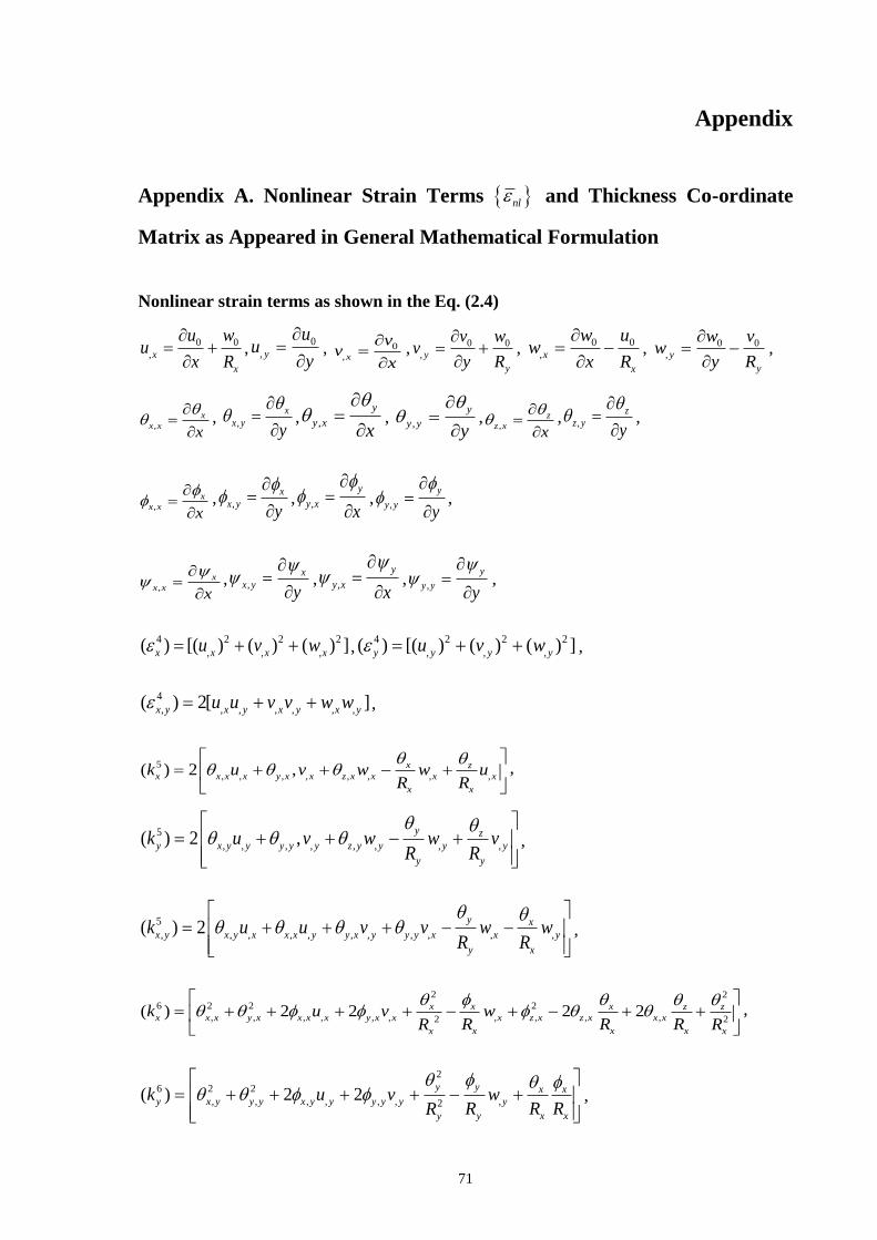
71
Appendix
Appendix A. Nonlinear Strain Terms nl and Thickness Co-ordinate
Matrix as Appeared in General Mathematical Formulation
Nonlinear strain terms as shown in the Eq. (2.4)
0 0
,x
x
u wu
x R
,
0
, y
uu
y
, 0
,x
vv
x
, 0 0
, y
y
v wv
y R
, 0 0
,x
x
w uw
x R
, 0 0
, y
y
w vw
y R
,
,
x
x xx
, ,
x
x yy
, ,
y
y xx
, ,
y
y yy
,
,
z
z xx
, ,
z
z yy
,
,
x
x xx
, ,
x
x yy
, ,
y
y xx
, ,
y
y yy
,
,
x
x xx
, ,
x
x yy
, ,
y
y xx
, ,
y
y yy
,
4 2 2 2
, , ,( ) [( ) ( ) ( ) ]x x x xu v w ,4 2 2 2
, , ,( ) [( ) ( ) ( ) ]y y y yu v w ,
4
, , , , , , ,( ) 2[ ]x y x y x y x yu u v v w w ,
5
, , , , , , , ,( ) 2 , x z
x x x x y x x z x x x x
x x
k u v w w uR R
,
5
, , , , , , , ,( ) 2 ,y z
y x y y y y y z y y y y
y y
k u v w w vR R
,
5
, , , , , , , , , , ,( ) 2y x
x y x y x x x y y x y y y x x y
y x
k u u v v w wR R
,
2 2
6 2 2 2
, , , , , , , , , ,2 2( ) 2 2 2 2x x x z z
x x x y x x x x y x x x z x z x x x
x x xx x
k u v wR R RR R
,
2
6 2 2
, , , , , , ,2( ) 2 2
y y x x
y x y y y x y y y y y y
y x xy
k u v wR R RR
,
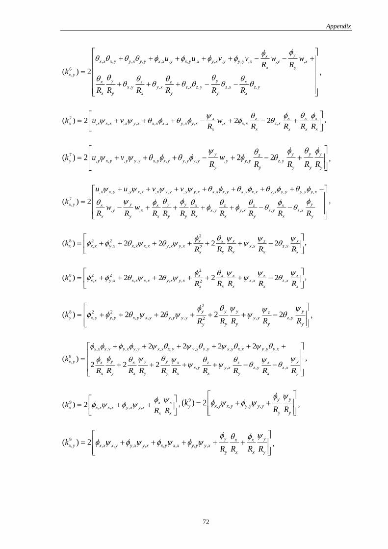
Appendix
72
, , , , , , , , , , , , , ,
6
,
, , , , , ,
( ) 2
yx
x x x y y x y y x x y x y x y x y y y x y x
x y
x y
y yx xz z
x y y x z x z y z x z y
x y x y y x
u u v v w wR R
k
R R R R R R
,
7
, , , , , , , , , , ,( ) 2 2 2x x x xz
x x x x x y x x x x x y x y x x x x z x
x x x x x
k u v wR R R R R
,
7
, , , , , , , , , , ,( ) 2 2 2y y y yz
y y x y y y y x y x y y y y y y y y z y
y y y y y
k u v wR R R R R
,
, , , , , , , , , , , , , , , ,
7
,
, , , , , ,
( ) 2
x x y y x x x y y y y x x x x y x y x x y x y y y y y x
y y y yx y x x x xz z
y x x y y x z y z x
x y x y y x x y x y
u u v v
kw w
R R R R R R R R R R
,
2
8 2 2
, , , , , , , ,2( ) 2 2 2 2x x x xz
x x x y x x x x x y x y x x x z x
x x x xx
kR R R RR
,
2
8 2 2
, , , , , , , ,2( ) 2 2 2 2x x x xz
x x x y x x x x x y x y x x x z x
x x x xx
kR R R RR
,
2
8 2 2
, , , , , , , ,2( ) 2 2 2 2
y y y yz
y x y y y x y x y y y y y y y z y
y y y yy
kR R R RR
,
, , , , , , , , , , , ,
8
,
, , , ,
2 2 2 2
( )2 2 2
x x x y y x y y x x x y y x y y x y x x y y y x
y y y yx y x x x xz z
x y y x z y z x
x y x y y x x y x y
k
R R R R R R R R R R
,
9
, , , ,( ) 2 x x
x x x x x y x y x
x x
kR R
,9
, , , ,( ) 2y y
y x y x y y y y y
y y
kR R
,
9
, , , , , , , , ,( ) 2y yx x
x y x x x y y x y x x y x x y y y x
y x x y
kR R R R
,
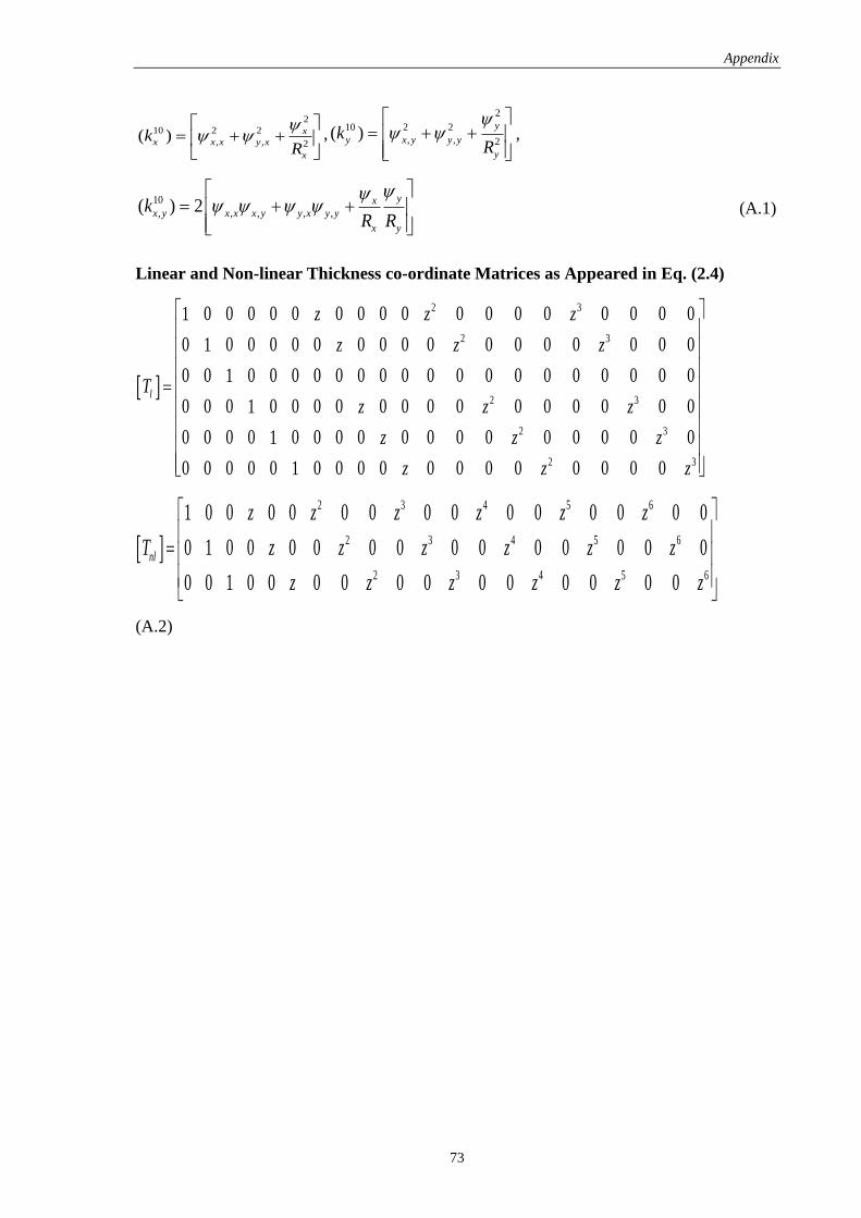
Appendix
73
2
10 2 2
, , 2( ) x
x x x y x
x
kR
,
2
10 2 2
, , 2( )
y
y x y y y
y
kR
,
10
, , , , ,( ) 2yx
x y x x x y y x y y
x y
kR R
(A.1)
Linear and Non-linear Thickness co-ordinate Matrices as Appeared in Eq. (2.4)
2 3
2 3
2 3
2 3
2 3
0 0 0 0 0 0 0 0 0 0 0 0 0 0 0 0 01
0 0 0 0 0 0 0 0 0 0 0 0 0 0 0 0 01
0 0 0 0 0 0 0 0 0 0 0 0 0 0 0 0 0 0 0 01
0 0 0 0 0 0 0 0 0 0 0 0 0 0 0 0 01
0 0 0 0 0 0 0 0 0 0 0 0 0 0 0 0 01
0 0 0 0 0 0 0 0 0 0 0 0 0 0 0 0 01
l
z z z
z z z
Tz z z
z z z
z z z
2 3 4 5 6
2 3 4 5 6
2 3 4 5 6
1 0 0 0 0 0 0 0 0 0 0 0 0 0 0
0 1 0 0 0 0 0 0 0 0 0 0 0 0 0
0 0 1 0 0 0 0 0 0 0 0 0 0 0 0
nl
z z z z z z
T z z z z z z
z z z z z z
(A.2)
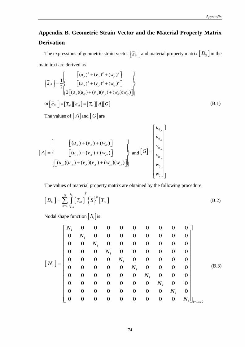
Appendix
74
Appendix B. Geometric Strain Vector and the Material Property Matrix
Derivation
The expressions of geometric strain vector nl
and material property matrix GD in the
main text are derived as
2 2 2
, , ,
2 2 2
, , ,
, , , , , ,
( ) ( ) ( )
1( ) ( ) ( )
2
2 ( )( ) ( )( ) ( )( )
x x x
nl y y y
x y x y x y
u v w
u v w
u u v v w w
or nl nl nl nlT T A G
(B.1)
The values of A and G are
, , ,
, , ,
, , , , , ,
( ) ( ) ( )
( ) ( ) ( )
( )( ) ( )( ) ( )( )
x x x
y y y
x y x y x y
u v w
A u v w
u u v v w w
and
,
,
,
,
,
,
0
0
0
0
0
0
x
y
x
y
x
y
u
u
vG
v
w
w
The values of material property matrix are obtained by the following procedure:
1
1
k
k
ThN k
G nl nl
k h
D T S T
(B.2)
Nodal shape function iN is
1 9
0 0 0 0 0 0 0 0 0
0 0 0 0 0 0 0 0 0
0 0 0 0 0 0 0 0 0
0 0 0 0 0 0 0 0 0
0 0 0 0 0 0 0 0 0
0 0 0 0 0 0 0 0 0
0 0 0 0 0 0 0 0 0
0 0 0 0 0 0 0 0 0
0 0 0 0 0 0 0 0 0
0 0 0 0 0 0 0 0 0
i
i
i
i
i
i
i
i
i
i
i i to
N
N
N
N
NN
N
N
N
N
N
(B.3)
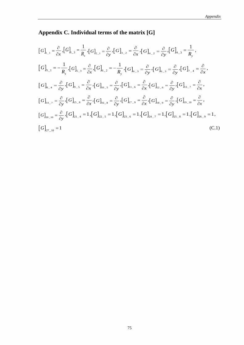
Appendix
75
Appendix C. Individual terms of the matrix [G]
1_1
Gx
, 1_ 3
1
x
GR
, 2 _1
Gy
, 3 _ 2
Gx
, 4 _ 2
Gy
, 4 _ 3
1
y
GR
,
5 _1
1
x
GR
, 5 _ 3
Gx
, 6 _ 2
1
y
GR
, 6 _ 3
Gy
, 6 _ 3
Gy
, 7 _ 4
Gx
,
8 _ 4
Gy
, 9 _ 5
Gx
, 10 _ 5
Gy
, 11_ 6
Gx
, 12 _ 6
Gy
, 13 _ 7
Gx
,
14 _ 7
Gy
, 15 _ 8
Gx
, 16 _ 8
Gy
, 17 _ 9
Gx
, 18 _ 9
Gy
, 19 _10
Gx
,
20 _10
Gy
, 21_ 4
1G , 22 _ 5
1G , 23 _ 6
1G , 24 _ 7
1G , 25 _ 8
1G , 26 _ 9
1G ,
27 _10
1G (C.1)
76
About the Author
Katariya Pankajkumar Vaikunthbhai, the author, was born on 24th May 1990 in Naliya,
Kachchh district, Gujarat, India. He has passed the Higher Secondary (10+2) Examination
under the GSHEB, Gujarat with distinction in 2007 and graduated in Aeronautical
Engineering with a first class degree from Sardar Vallabhbhai Patel Institute of Technology,
Vasad, Gujarat, India in the year 2011. On completion of his graduation, he planned to
continue his career in the field of research and joined M.Tech (Research) Program in NIT,
Rourkela, Odisha, India with specialization in Machine Design and Analysis in 2012. The
author’s current research interest lies in the field of composite structures and finite element
analysis.
In International Journals:
1. P. V. Katariya and S. K. Panda, “Vibration and Thermal Buckling Analysis of Curved
Panels,” Aircraft Engineering and Aerospace Technology. (revised)
2. P. V. Katariya and S. K. Panda, “Stability and Free Vibration Behaviour of Laminated
Composite Plate under Thermo-mechanical Loading,” International Journal of Applied
and Computational Mathematics. (communicated)
In Conference Proceedings:
1. P. V. Katariya and S. K. Panda, “Modal Analysis of Laminated Composite Spherical
Shell Panels using Finite Element Method,” Proceedings of International Conference
on Structural Engineering and Mechanics (ICSEM), Dec 20-22 2013, NIT Rourkela,
Odisha, India.
2. P. V. Katariya and S. K. Panda, “Stability and vibration behavior of laminated
composite and sandwich structures,” Proceedings of 2nd KIIT International Symposium
on Advances in Automotive Technology (KIIT-SAAT), Dec 20-21 2013, KIIT
Bhubaneswar, Odisha, India.
3. P. V. Katariya and S. K. Panda, “Thermo-Mechanical Stability Analysis of Composite
Cylindrical Panels,” ASME 2013 Gas Turbine India conference (ASME GTINDIA
2013), Dec 5-6 2013, Bangalore, Karnataka, India.
4. P. V. Katariya and S. K. Panda, “A parametric study on free vibration behavior of
laminated composite curved panels,” Proceedings of International Conference on
77
Advances in Mechanical Engineering (ICAME), May 29-31 2013, COEP, Pune,
Maharashtra, India.
5. P. V. Katariya and S. K. Panda, “Stability Analysis of Laminated Composite
Cylindrical Shell Structure under Uniaxial loading,” Proceedings of All India Seminar
on Recent Advances in Mechanical Engineering, Mar 16-17 2013, Bhubaneswar,
Odisha, India.
6. P. V. Katariya and S. K. Panda, “Thermo-mechanical stability analysis of laminated
composite plate using FEM,” Proceedings of 1st KIIT International Symposium on
Advances in Automotive Technology (KIIT-SAAT), Jan 11-12, 2013, KIIT
Bhubaneswar, Odisha, India.