Embed Size (px)
Citation preview

This article was downloaded by: [Moskow State Univ Bibliote]On: 18 February 2014, At: 09:29Publisher: Taylor & FrancisInforma Ltd Registered in England and Wales Registered Number: 1072954 Registered office: Mortimer House,37-41 Mortimer Street, London W1T 3JH, UK
Mechanics of Advanced Materials and StructuresPublication details, including instructions for authors and subscription information:http://www.tandfonline.com/loi/umcm20
Free Vibration Analysis of Composite Laminates withDelamination Based on State Space TheoryDinghe Li a & Guanghui Qing aa College of Aeronautical Engineering , Civil Aviation University of China , Tianjin , ChinaAccepted author version posted online: 17 Sep 2012.Published online: 30 Jan 2014.
To cite this article: Dinghe Li & Guanghui Qing (2014) Free Vibration Analysis of Composite Laminates withDelamination Based on State Space Theory, Mechanics of Advanced Materials and Structures, 21:5, 402-411, DOI:10.1080/15376494.2012.697602
To link to this article: http://dx.doi.org/10.1080/15376494.2012.697602
PLEASE SCROLL DOWN FOR ARTICLE
Taylor & Francis makes every effort to ensure the accuracy of all the information (the “Content”) containedin the publications on our platform. However, Taylor & Francis, our agents, and our licensors make norepresentations or warranties whatsoever as to the accuracy, completeness, or suitability for any purpose of theContent. Any opinions and views expressed in this publication are the opinions and views of the authors, andare not the views of or endorsed by Taylor & Francis. The accuracy of the Content should not be relied upon andshould be independently verified with primary sources of information. Taylor and Francis shall not be liable forany losses, actions, claims, proceedings, demands, costs, expenses, damages, and other liabilities whatsoeveror howsoever caused arising directly or indirectly in connection with, in relation to or arising out of the use ofthe Content.
This article may be used for research, teaching, and private study purposes. Any substantial or systematicreproduction, redistribution, reselling, loan, sub-licensing, systematic supply, or distribution in anyform to anyone is expressly forbidden. Terms & Conditions of access and use can be found at http://www.tandfonline.com/page/terms-and-conditions
Mechanics of Advanced Materials and Structures (2014) 21, 402–411Copyright C© Taylor & Francis Group, LLCISSN: 1537-6494 print / 1537-6532 onlineDOI: 10.1080/15376494.2012.697602
Free Vibration Analysis of Composite Laminates withDelamination Based on State Space Theory
DINGHE LI and GUANGHUI QING
College of Aeronautical Engineering, Civil Aviation University of China, Tianjin, China
Received 28 September 2010; accepted 23 October 2011.
A semi-analytical solution based on the modified H-R (Hellinger-Reissner) variational principle and a nonlinear spring-layer modelis presented to analyze the free vibration problem of laminates with a delamination in the Hamilton system. This nonlinear spring-layer model between the upper and lower sub-laminates ensures the exact continuous transverse stresses and displacements in theun-delaminated region by specifying the infinite values of springs and avoids the possibility of penetration phenomenon in thedelaminated region. As an application of this method, the influence of the delamination size, depth, and boundary conditions on thefirst three natural frequencies of delaminated composite laminates is investigated.
Keywords: free vibration analysis, delamination, composite laminates, Hamilton system, modified H-R variational principle
1. Introduction
The laminated composites allow engineers to design struc-tural components by adjusting the orientations, thickness, andstacking sequence of the fiber-reinforced laminate to providea laminate that possesses the desired stiffness and strength.Of course, the high strength-to-weight and high stiffness-to-weight ratios are also two primary reasons that the compositelaminates have been widely used in various engineering struc-tures. However, the onset and growth of delaminations areof great interest in applications of composite structures sincedelaminations are one of the major failure modes.
The history of free vibration analysis of the delaminatedstructures began with the pioneering work carried out in thelast stage of the 20th century [1, 2]. Since then, the problemhas been studied extensively. Della and Shu [3] provided a rel-evant survey on the various analytical models and numericalanalyses for the free vibration of delaminated composite struc-tures. It should be mentioned that several extensive studies forfree vibrations of such structures with multiple delaminations[4–6] have been conducted recently. Generally, we can nowobtain a basic understanding of the influence of delaminationon the natural frequencies and the mode shapes of compositelaminates by the published works. Three basic assumptionsmade in this theory are: (1) no delamination growth, (2) theneglect of normal strains, and (3) no contact at delaminatedsurfaces.
Address correspondence to Dinghe Li, College of AeronauticalEngineering, Civil Aviation University of China, Tianjin 300300,China. E-mail: [email protected]
Recently, Tafreshi [7, 8] presented an efficient modeling ap-proach (double-layer model) of the delamination buckling forcomposite laminated cylindrical shells based on ABAQUS.The constraint equations in the areas of delamination werereplaced by the contact elements (GAP) between the corre-sponding nodes of the exterior and interior sublaminates. Thecontact elements can prevent the interpenetration of the nodesof the two cylindrical layers in the delamination region. Inter-penetration would neglect the behavior of real laminates andresult in incorrect estimations of the critical load.
However, it is not difficult to notice that most of the existingvarious methods for the free vibration analysis of the delami-nated structures belong to the methodologies of the Lagrangesystem (i.e., the variables of displacements are only consid-ered in the control equation of models). Currently, main ap-proaches can be employed for analysis of composite laminatedplates with delamination: equivalent single layer theory (clas-sical laminate theory [CLT] and shear deformation laminatedplate theories [FSDT]) [9–13] and three-dimensional elasticitytheory (traditional 3D elasticity formulations and layerwisetheory [LW]) [14, 15]. It well known that the above theoriesare established on some displacements and stresses hypothesis.CLT ignores transverse shear stresses and FSDT does not pro-vide sufficient accuracy because of the use of shear correctionfactors. The LW is an alternative because it is capable of mod-eling continuities of displacements and the discontinuities ofthe derivatives of displacements with respect to the thicknesscoordinate (C0-continuity) [16]. However, the computationaleffort increases with the number of plies. Therefore, the errorswill increase as the thickness of the plate increases and thestress at interface cannot be exactly calculated.
In recent years, the state space approach of elastomechan-ics, which is employed in the analysis of control systems of
Dow
nloa
ded
by [
Mos
kow
Sta
te U
niv
Bib
liote
] at
09:
29 1
8 Fe
brua
ry 2
014

Free Vibration, Composite Laminates, Delamination 403
current significance, has attracted the attention of a number ofinvestigators who are interested in the problems of laminatedstructures [17–59]. In the state space approach, two types ofvariables (i.e., the transverse stresses and displacements) aresynchronously considered in the control equation. The ap-proach to interlaminar continuity is different from some ofthe Zig-Zag strategies. Because of the transfer matrix tech-nique being employed, the solution provides exact continuoustransverse stresses and displacement field across the thicknessof a laminated structure. Another significant difference fromthe classical layer-wise methods is that the scale of the finalgoverning equation system is independent of the thickness andthe number of layers of a structure.
The governing equations of the two-dimensional or three-dimensional problems in the state space framework are of-tentimes named as state-vector equation [17]. If the govern-ing equation is derived from the modified Hellinger-Reissner(H-R) variational principle, it is also called Hamilton canon-ical equation [45, 46]. By the last 20 years of development,a lot of special algorithms have been developed, such as se-ries approach [18–43, 55–58], semi-analytical solution [45–54],asymptotic method [59], and so on. Among these approaches,the semi-analytical solution is a remarkable numerical methodfor complex engineering problems.
For making full use of the advantages of the semi-analyticalsolution in a Hamilton system and the nonlinear spring-layermodel, a new efficient mathematical model for the free vibra-tion analysis of the composite laminates with a delaminationis presented by separate consideration of the sub-laminatesof structures in this article. The present three-dimensionalsemi-analytical model, with no initial assumptions regardingdisplacement and stress, accounts for the transverse shear de-formation and rotary in the governing equation of structure.And the spring-layer model between the upper and lower sub-laminates is consistent with the physical behavior of contin-uous transverse stresses and displacements in the undelami-nated region and avoids the possibility of material penetrationphenomenon in the delaminated region.
2. Mathematical Model of Laminates with aDelaminated Region
2.1. The Modified H-R Variational Principle
For isotropic, orthotropic, or anisotropic elasticity solids, themodified H-R variational principle in a three-dimensionalCartesian coordinate system can be expressed as [51–55]:
�� = �
∫∫∫V
(PT ∂ Q
∂ z− H
)dV+�
∫∫SA
(�T
1 Bpq − �T0 B pq
)dS,
(1)
in which Q = [u v w]T, (u v w) are the total displacementcomponents along (x, y, z) coordinates, respectively. P =[�xz �yz �zz]T, (�xz �yz �zz) are the out-of-plane (i.e., trans-verse) stresses. The superscript T signifies a matrix trans-position; H is Hamiltonian; V is referred to the volume
considered; SA is the surface over the volume; and Bpq =[ px(u − u) py(v − v) pz(w − w) ]T, pi (i = x, y, z) are thestress boundary conditions in three coordinate directions,respectively. u, v, and w are the prescribed displacementboundary conditions along (x, y, z) coordinates, respec-tively. B pq = [ pxu pyv pzw ]T, pi (i = x, y, z) are the pre-scribed stress boundary conditions in the (x, y, z) direc-tions, respectively. �1 = [ �x − 1 �y − 1 �z − 1 ]T and �0 =[ �x �y �z ]T are the characteristic coefficients that are in-troduced, especially in which the value of �i (i = x, y, z) is 1or 0. �i (i = x, y, z) = 1 marks the stress boundary cases inthree coordinates directions, respectively. �i (i = x, y, z) = 0marks the displacement boundary cases in three coordinatesdirections, respectively.
The Hamiltonian H in Eq. (1) can be stated as:
H = −PT(G1 Q) − PT� T21(G2 Q) − 1
2(G2 Q)T� 22(G2 Q)
+ 12
PT� 11 P − 12
QTΩQ − FT Q. (2)
Here G1 = [0 0 �0 0 �0 0 0
], G2 = [� 0 00 � 0� � 0
], � = ∂/∂x, and
� = ∂/∂y. Ω = Diag(��2)3×3, where � is unit density ofa material, � is the natural frequency of structure. F =−[ fx fy fz ]T denotes the vector of the body forces or ex-ternal loading.
For the isotropic and orthotropic materials:
� 11 = � T11 =
⎡⎢⎣
s1 0 0
0 s2 0
0 0 s3
⎤⎥⎦ , � 21 =
⎡⎢⎣
0 0 −s4
0 0 −s5
0 0 0
⎤⎥⎦,
� 22 = � T22 =
⎡⎢⎣
s6 s7 0
s7 s8 0
0 0 s9
⎤⎥⎦, (3)
where s1 = 1/c55, s2 = 1/c44, s3 = 1/c33, s4 = −c13/c33, s5 =−c23/c33, s6 = c11 − c2
13/c33, s9 = c66, s7 = c12 − c13c23/c33,
s8 = c22 − c223/c33, and ci j (i, j = 1, 2, 3, 4, 5, 6) are known as
the stiffness coefficients of a material.The in-plane stresses vector Pin , which is not included in
Eq. (1), can be expressed as:
Pin = � 21 P + � 22G2 Q. (4)
Based on Eq. (4), the stress boundary conditions can be sim-plified as follows:
px = nx(s6∂xu + s7∂yv − s4�zz) + nys9(∂yu + ∂xv)py = nxs9(∂yu + ∂xv) + ny(s7∂xu + s8∂yv − s5�zz),pz = nx�xz + ny�yz
(5)
in which ni (i = x, y) are the unit outward normalcomponents.
Dow
nloa
ded
by [
Mos
kow
Sta
te U
niv
Bib
liote
] at
09:
29 1
8 Fe
brua
ry 2
014

404 D. Li and G. Qing
2.2. Formulation of 4-Node Quadrilateral Element
For convenience, we use the same interpolation functionsto express the stress and displacement variables. Therefore,the out-of-plane stresses �xz, �yz, �zz and displacementsu , v, w of a 4-node quadrilateral element can be stated as:
�xz(, , z) = Φ�xze(z), u(, , z) = Φue(z)�yz(, , z) = Φ�yze(z), v(, , z) = Φve(z),�zz(, , z) = Φ�zze(z), w(, , z) = Φw e(z)
(6)
where notation z is the thickness of an element, Φ =[N1 N2 N3 N4]T, Ni (, ) = [(1 + i )(1 + i )]/4, (i =1, 2, 3, 4).
From Eq. (6), we arrive at the expression:
{PQ
}=
[N 00 N
]{Pe
Qe
}, (7)
in which N = Diag(Φ)3×3, Pe = [�xze(z) �yze(z) �zze(z)]T,Qe = [ ue(z) ve(z) w e(z) ]T.
Substitution for P and Q from Eq. (7) into Eq. (1), applyingthe tools of variational calculus and integrating, the first termis:
[L 0
0 L
]ddz
{Pe(z)
Qe(z)
}
=[
AT11 A12
A21 −A11
]{Pe(z)
Qe(z)
}+
{Ξe0
}, (8)
where L = ∫ 1−1
∫ 1−1 NT N|J|dd , AT
11 = ∫ 1−1
∫ 1−1((G1 N)T N +
(G2 N)T� 21 N)|J|dd , Ξe = ∫ 1−1
∫ 1−1 NT F |J|dd , A12 = AT
12
= ∫ 1−1
∫ 1−1 ((G2 N)T� T
22(G2 N) + Ω)|J|dd , AT21 = ∫ 1
−1
∫ 1−1 NT
� 11 N|J|dd , and J is Jacobin matrix.The boundary term can be reduced to the following form:
Boundary term =[
BT11 B120 −B11
]{Pe(z)Qe(z)
}+
[D11 D120 D22
]
×{
Pe(z)Qe(z)
}, (9)
where B11 = ∫SA
(G3 N)T N(G3 N)T N dS, B12 = BT12 = ∫
SA(NT
(G4 N) + (G4 N)T N)dS, D11 = − ∫SA
NTΛ0dS, Λ0 = Diag(�x,
�y, �z), D12 = − ∫SA
(G4 N)TdS, and D22 = ∫SA
(G3 N)TdS.
G3 =
⎡⎢⎣
0 0 −nxs4(�x − 1)
0 0 −nys5(�y − 1)
nx(�z − 1) ny(�z − 1) 0
⎤⎥⎦ ,
G4 =
⎡⎢⎣
(nxs6� + nys9�)(�x − 1) (nxs7� + nys9�)(�x − 1) 0
(nxs9� + nys7�)(�y − 1) (nxs9� + nys8�)(�y − 1) 0
0 0 0
⎤⎥⎦ .
Therefore, a total formulation of the 4-node quadrilateralelement may be expressed as:
[L 0
0 L
]ddz
{Pe(z)
Qe(z)
}=
[AT
11 + BT11 A12 + B12
A21 −A11 − B11
]
×{
Pe(z)
Qe(z)
}+
{F e1(z)
F e2(z)
}, (10)
in which F e1(z) = D11 P(z)e + D12 Qe(z) + Ξe, F e2 =D22 Qe(z).
If Pe(z) and Qe(z) of an element are known, the in-planestress can be evaluated from Eq. (4).
2.3. Mathematic Model of Laminates in Hamilton System
The assemblage from the above 4-node elements to the levelof a layer is made as a usual method; the non-homogenousgoverning equation of a layer with n nodes is:
[Σ 0
0 Σ
]ddz
{p(z)
q(z)
}=
[MT
11 M12M21 −M11
] {p(z)
q(z)
}+
{F p(z)
Fq (z)
},
(11)where p(z) = [�xz1(z) �xz2(z) · · · �xzn(z) �yz1(z) �yz2(z)· · · �xz1(z) �zz1(z) �xz2(z) · · · �zzn (z)]T and q(z) =[ u1(z) u2(z) · · · un(z) v1(z) v2(z) · · · vn(z) w1(z) w2(z) · · · w n(z)]T denote the transverse stress vector and the dis-placement vector, respectively. Σ = ΣT, M12 = MT
12,and M21 = MT
21 are the equivalent stiffness matri-ces. F p(z) = [ fp1(z) fp2(z) · · · fp3n(z) ]T and Fq (z) =[ fq1(z) fq2(z) · · · fq3n(z) ]T are the equivalent external loadvectors.
The exact solution to Eq. (11) of kth layer is:
Hk(z) = Tk(z)Hk(0) + Fk(z), (12)
in which Hk(z) = [ pk(z) q k(z)]T, Hk(0) = [ pk(0) q k(0)]T,Fk(z) = ∫ z
0 exp(Kk.(z − � )Fk(� )d� , Tk(z) = exp(Kk.z),
Kk = [Σ−1
k 00 Σ−1
k][ MT
11k M12kM21k −M11k
], and Fk(� ) = [�−1
k 00 �−1
k]
{ Fpk(� )Fqk(� ) }.
Assuming each layer of a laminate possesses an identicalelement mesh, based on the interlaminar compatibility condi-tions, the recurrence formulation of a laminate with l layersis:
Hl (hl ) =(
l∏k=1
Tk
)H1(0) +
(l∏
k=2
Tk
)F1(hk)
+(
l∏k=3
Tk
)F2(h2) + · · · + F l (hl ), (13)
where hk (k = 1, 2, · · · l) is the thickness of each layer.
Dow
nloa
ded
by [
Mos
kow
Sta
te U
niv
Bib
liote
] at
09:
29 1
8 Fe
brua
ry 2
014
Free Vibration, Composite Laminates, Delamination 405
delaminated region ΩD
l1
l
a
b
lower sub-laminate
upper sub-laminate
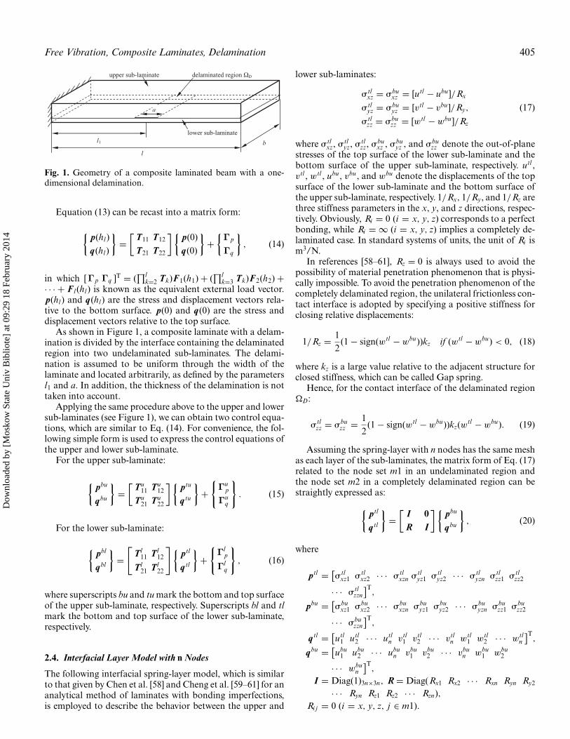
Fig. 1. Geometry of a composite laminated beam with a one-dimensional delamination.
Equation (13) can be recast into a matrix form:
{p(hl )
q(hl )
}=
[T11 T12
T21 T22
] {p(0)
q(0)
}+
{Γp
Γq
}, (14)
in which [Γp Γq ]T = (∏l
k=2 Tk)F1(h1) + (∏l
k=3 Tk)F2(h2) +· · · + F l (hl ) is known as the equivalent external load vector.p(hl ) and q(hl ) are the stress and displacement vectors rela-tive to the bottom surface. p(0) and q(0) are the stress anddisplacement vectors relative to the top surface.
As shown in Figure 1, a composite laminate with a delam-ination is divided by the interface containing the delaminatedregion into two undelaminated sub-laminates. The delami-nation is assumed to be uniform through the width of thelaminate and located arbitrarily, as defined by the parametersl1 and a. In addition, the thickness of the delamination is nottaken into account.
Applying the same procedure above to the upper and lowersub-laminates (see Figure 1), we can obtain two control equa-tions, which are similar to Eq. (14). For convenience, the fol-lowing simple form is used to express the control equations ofthe upper and lower sub-laminate.
For the upper sub-laminate:
{pbu
qbu
}=
[Tu
11 Tu12
Tu21 Tu
22
]{ptu
q tu
}+
{Γu
p
Γuq
}. (15)
For the lower sub-laminate:
{pbl
qbl
}=
[Tl
11 Tl12
Tl21 Tl
22
] {ptl
q tl
}+
{Γl
p
Γlq
}, (16)
where superscripts bu and tu mark the bottom and top surfaceof the upper sub-laminate, respectively. Superscripts bl and tlmark the bottom and top surface of the lower sub-laminate,respectively.
2.4. Interfacial Layer Model with n Nodes
The following interfacial spring-layer model, which is similarto that given by Chen et al. [58] and Cheng et al. [59–61] for ananalytical method of laminates with bonding imperfections,is employed to describe the behavior between the upper and
lower sub-laminates:
�tlxz = �bu
xz = [utl − ubu ]/Rx
�tlyz = �bu
yz = [vtl − vbu ]/Ry,
�tlzz = �bu
zz = [wtl − wbu ]/Rz
(17)
where �tlxz, �tl
yz, �tlzz, �bu
xz , �buyz , and �bu
zz denote the out-of-planestresses of the top surface of the lower sub-laminate and thebottom surface of the upper sub-laminate, respectively. utl ,vtl , wtl , ubu , vbu , and wbu denote the displacements of the topsurface of the lower sub-laminate and the bottom surface ofthe upper sub-laminate, respectively. 1/Rx, 1/Ry, and 1/Rz arethree stiffness parameters in the x, y, and z directions, respec-tively. Obviously, Ri = 0 (i = x, y, z) corresponds to a perfectbonding, while Ri = ∞ (i = x, y, z) implies a completely de-laminated case. In standard systems of units, the unit of Ri ism3/N.
In references [58–61], Rz = 0 is always used to avoid thepossibility of material penetration phenomenon that is physi-cally impossible. To avoid the penetration phenomenon of thecompletely delaminated region, the unilateral frictionless con-tact interface is adopted by specifying a positive stiffness forclosing relative displacements:
1/Rz = 12
(1 − sign(wtl − wbu))kz if (wtl − wbu) < 0, (18)
where kz is a large value relative to the adjacent structure forclosed stiffness, which can be called Gap spring.
Hence, for the contact interface of the delaminated region�D:
�tlzz = �bu
zz = 12
(1 − sign(wtl − wbu))kz(wtl − wbu). (19)
Assuming the spring-layer with n nodes has the same meshas each layer of the sub-laminates, the matrix form of Eq. (17)related to the node set m1 in an undelaminated region andthe node set m2 in a completely delaminated region can bestraightly expressed as:
{ptl
q tl
}=
[I 0R I
] {pbu
qbu
}, (20)
where
ptl = [�tl
xz1 �tlxz2 · · · �tl
xzn �tlyz1 �tl
yz2 · · · �tlyzn �tl
zz1 �tlzz2
· · · �tlzzn
]T,
pbu = [�bu
xz1 �buxz2 · · · �bu
xzn �buyz1 �bu
yz2 · · · �buyzn �bu
zz1 �buzz2
· · · �buzzn
]T,
q tl = [utl
1 utl2 · · · utl
n vtl1 vtl
2 · · · vtln wtl
1 wtl2 · · · wtl
n
]T,
qbu = [ubu
1 ubu2 · · · ubu
n vbu1 vbu
2 · · · vbun wbu
1 wbu2
· · · wbun
]T,
I = Diag(1)3n×3n, R = Diag(Rx1 Rx2 · · · Rxn Ryn Ry2
· · · Ryn Rz1 Rz2 · · · Rzn),Ri j = 0 (i = x, y, z, j ∈ m1).
Dow
nloa
ded
by [
Mos
kow
Sta
te U
niv
Bib
liote
] at
09:
29 1
8 Fe
brua
ry 2
014

406 D. Li and G. Qing
Consider the contact interface of the delaminated region�D:
Ri j → ∞ (i = x, y, j ∈ m2)
Rzj = h2E
if (wtlj − wbu
j ) < 0 ( j ∈ m2),
Rzj = ∞ if (wtlj − wbu
j ) ≥ 0 ( j ∈ m2)
(21)
in which E is the elasticmodulus of z-direction and h is thick-ness of a laminate. As a matter of fact, the following valueswithout dimension, which can provide reliable numerical re-sults and avoid the numerical instabilities, are specified in ourcomputer program:
Rxj = Ryj = 109 ( j ∈ m2), Rzj = 109 if (wtlj − wbu
j )≥ 0 ( j ∈ m2). (22)
2.5. Mathematical Model of a Laminate with aDelaminated Region
From Eqs. (20), (15), and (16), the final control equation of alaminate with a delamination is:
{pbl
qbl
}=
[E11 E12
E21 E22
] {ptu
q tu
}+
{Θp
Θq
}, (23)
where
[E11 E12
E21 E22
]=
[Tl
11 Tl12
Tl21 Tl
22
] [I 0R I
] [Tu
11 Tu12
Tu21 Tu
22
],
{Θp
Θq
}
=[
Tl11 Tl
12
Tl21 Tl
22
] [I 0R I
]{Γu
p
Γuq
}+
{Γl
p
Γlq
}.
Obviously, Eq. (23) is formally consistent with Eq. (15)or Eq. (16) of the undelaminated sub-laminates. One of theprimary characteristics of the model is that the known infor-mation and contact interface of the delaminated region areburied by Eq. (20). As a matter of fact, Eq. (20) is a simpletransfer matrix that can be immediately used to establish thecontrol equation of structure.
For the natural frequency problem, pbl = 0, ptu = 0, Γ′1 =
0, and Γ′2 = 0, the following equation can be deduced from
Eq. (23):
E12q tu = 0. (24)
To obtain the nontrivial solution, the determinant of thecharacteristic matrix must be zero:
|E12| = 0. (25)
3. Numerical Examples
Example 1. The cross-ply laminated beam considered (with l× b = 127 × 12.7 mm) has eight elastic layers and is made ofgraphite-epoxy composite with the fiber-orientation [0/90/]2salong the x axis. All of the layers have the same thickness(h = 0.127 mm) and the material properties (E11 = 134.355GPa, E22 = 10.335 GPa, G12 = 4.995 GPa, �12 = 0.33, �= 3825.6 Kg/m3). The geometry of the delaminated beam is
20 40 60 80 100 120 140 160 18082.1
82.2
82.3
82.4
82.5
82.6
82.7
82.8
82.9
Number of nodes
Fun
dam
enta
l fre
quen
cy
20 40 60 80 100 120 140 160 18069.65
69.7
69.75
69.8
69.85
69.9
69.95
Number of nodes
Fun
dam
enta
l fre
quen
cy
(a) (b)
Fig. 2. Convergence curves of fundamental frequency for the composite laminated beam with/without delamination: (a) Laminatedbeam without delamination; (b) Laminated beam with delamination (the delamination is embedded between the 4th layer and 5thlayer).
Dow
nloa
ded
by [
Mos
kow
Sta
te U
niv
Bib
liote
] at
09:
29 1
8 Fe
brua
ry 2
014

Free Vibration, Composite Laminates, Delamination 407
Table 1. Fundamental frequency of delamination that embedded along one of the four ply interfaces
0a 1 2 3 4
Present 82.156 78.661 77.963 70.308 69.682Analytical [62] 82.042 (1.3895)b 75.843 (3.7156) 75.137 (3.7611) 68.776 (2.2275) 67.361 (3.4456)Experiment [62] 79.875 (2.8557) 75.375 (4.3595) 79.625 (2.0872) 78.375 (10.2928) 78.376 (11.0926)
aDelamination location. For example, i denotes the delamination along interface i, 0 denotes that there is no delamination in the laminated beam.bValues in parentheses are percentage error (%) compared with the analytical results or experiment values, which may be considered the accuratesolution.
shown in Figure 1. The delamination is assumed to be uniformthrough the width of the beam and centered at the midspanof the beam. Within the laminated beam, a delamination canbe embedded along one of the first four ply interfaces. Andthe delamination length is 25.4 mm. This is an example that isselected to validate the present method.
Convergence curves of fundamental frequency for the com-posite laminated beam with/without delamination are studiedfirst. It is clear that the present model has a good convergencecapability and the undelaminated beam and the delaminatedbeam possess the same convergence curves (Figure 2) as anundelaminated beam.
The results obtained by the present method, as listed inTable 1, are in good agreement with the analytical resultsand experiment values, which are given in Shen and Grady[62]. The analytical results presented were obtained by an-alytical model B. And the experiment values were obtainedfrom specimen 1. Good agreement has been achieved betweenthe predictions and the analytical results and experimentvalues.
Example 2. The cross-ply laminated beam considered (with l× b = 1 × 0.3, as shown in Figure 3) has 10 elastic layers and ismade of graphite-epoxy composite with the fiber-orientation[0/90/0/90/0]s along the x axis. All of the layers have thesame thickness (h = 0.01) and the material properties. Thenon-dimensionalized material properties of the single layer
are as follows:
E1 = 0.886426, E2 = 0.465371, E3 = 0.50473,
G12 = 0.26293, G23 = 0.26681, G31 = 0.15991,
v12 = 0.231243, v31 = 0.0321923, v23 = 0.195952, � = 1.
In this example, the effects of the delamination size, the de-lamination depth, and the boundary conditions on the naturalfrequencies are studied.
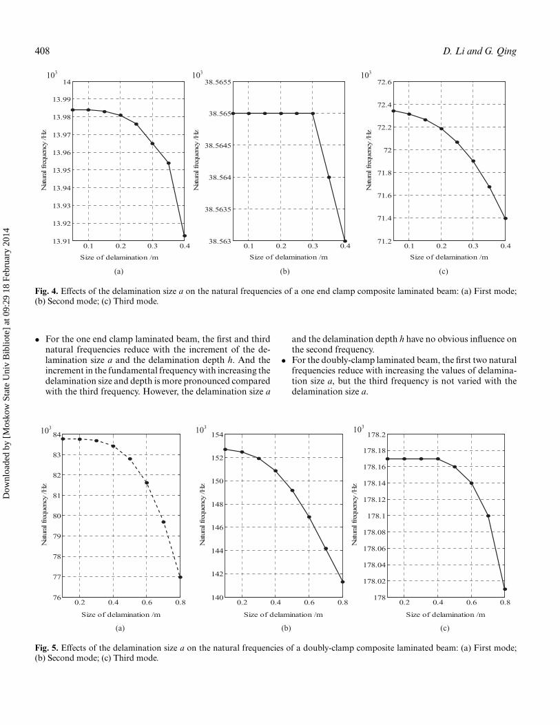
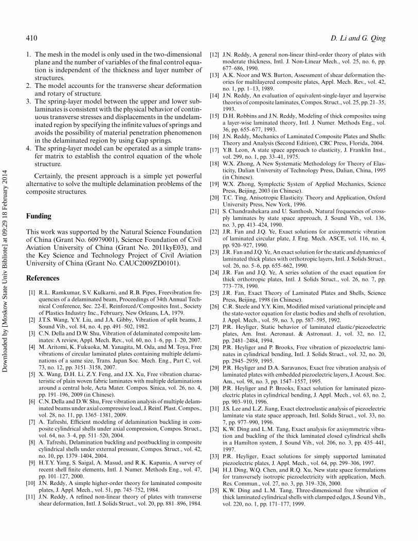
In order to study the effect of the delamination size onthe natural frequencies, the first three natural frequencies areobtained for various delamination size a. Here, delaminationdepth h is kept in between the first layer and the second layer.The delamination size a is varied individually from 0.05 to0.4 and 0.1 to 0.8 for the one end clamp and doubly-clampcomposite laminated beam, respectively. The influence curvesof the delamination size a on the first three natural frequenciesare given in Figures 4 and 5.
Five values of delamination depth h are selected to studythe effect of a delamination depth on the first three natural fre-quencies. The delamination size a is kept individually equal to0.2 and 0.3 for the one end clamp and doubly-clamp compos-ite laminated beams. The influence curves of the delaminationdepth on the first three natural frequencies are given in Fig-ures 6 and 7, respectively.
It can be seen from Figures 4–7 that:
h
a
lb b
l
h
a
l/2
(a) one end clamp beam (b) doubly-clamp beam
delaminated region ΩD
Fig. 3. Schematic of the delamination location, depth, and the boundary conditions.
Dow
nloa
ded
by [
Mos
kow
Sta
te U
niv
Bib
liote
] at
09:
29 1
8 Fe
brua
ry 2
014
408 D. Li and G. Qing
(a) (b) (c)
0.1 0.2 0.3 0.413.91
13.92
13.93
13.94
13.95
13.96
13.97
13.98
13.99
14
Size of delamination /m
Nat
ural
fre
quen
cy /H
z
0.1 0.2 0.3 0.438.563
38.5635
38.564
38.5645
38.565
38.5655
Size of delamination /m
Nat
ural
fre
quen
cy /H
z
0.1 0.2 0.3 0.471.2
71.4
71.6
71.8
72
72.2
72.4
72.6
Size of delamination /m
Nat
ural
fre
quen
cy /H
z
103 103 103
Fig. 4. Effects of the delamination size a on the natural frequencies of a one end clamp composite laminated beam: (a) First mode;(b) Second mode; (c) Third mode.
• For the one end clamp laminated beam, the first and thirdnatural frequencies reduce with the increment of the de-lamination size a and the delamination depth h. And theincrement in the fundamental frequency with increasing thedelamination size and depth is more pronounced comparedwith the third frequency. However, the delamination size a
and the delamination depth h have no obvious influence onthe second frequency.
• For the doubly-clamp laminated beam, the first two naturalfrequencies reduce with increasing the values of delamina-tion size a, but the third frequency is not varied with thedelamination size a.
0.2 0.4 0.6 0.876
77
78
79
80
81
82
83
84
Size of delamination /m
Nat
ural
fre
quen
cy /H
z
0.2 0.4 0.6 0.8140
142
144
146
148
150
152
154
Size of delamination /m
Nat
ural
fre
quen
cy /H
z
0.2 0.4 0.6 0.8178
178.02
178.04
178.06
178.08
178.1
178.12
178.14
178.16
178.18
178.2
Size of delamination /m
Nat
ural
fre
quen
cy /H
z
103 103 103
(a) (b) (c)
Fig. 5. Effects of the delamination size a on the natural frequencies of a doubly-clamp composite laminated beam: (a) First mode;(b) Second mode; (c) Third mode.
Dow
nloa
ded
by [
Mos
kow
Sta
te U
niv
Bib
liote
] at
09:
29 1
8 Fe
brua
ry 2
014

Free Vibration, Composite Laminates, Delamination 409
1 2 3 4 513.968
13.97
13.972
13.974
13.976
13.978
13.98
13.982
Depth of delamination
Nat
ural
fre
quen
cy /H
z
1 2 3 4 537.5
38
38.5
39
39.5
40
Depth of delamination
Nat
ural
fre
quen
cy /H
z
1 2 3 4 571.4
71.5
71.6
71.7
71.8
71.9
72
72.1
72.2
Depth of delamination
Nat
ural
fre
quen
cy /H
z
103103 103
(a) (b) (c)
Fig. 6. Effects of the delamination depth h on the natural frequencies of a one end clamp composite laminated beam: (a) First mode;(b) Second mode; (c) Third mode.
• For two kinds of boundary conditions, the decrease of thenatural frequencies of the doubly-clamp laminated beamwith increasing the delamination sizes is larger than that ofthe one end clamp.
4. Concluding Remarks
In this article, a free vibration analysis model for the delami-nated multi-layered plates was presented in the Hamilton sys-
tem. To demonstrate the excellent predictive capability, themodel was applied to compute the natural frequencies of com-posite laminated beams with a through-width delamination.The results obtained by a present analysis model are comparedwith those by the analytical method. In addition, the influenceof the delamination size, depth, and boundary conditions onthe first three natural frequencies was investigated for the oneend clamp and doubly-clamp composite laminated beams.
Based upon the mathematical model studied in this article,the following remarks can be made:
1 2 3 4 5
83.35
83.4
83.45
83.5
83.55
83.6
83.65
83.7
83.75
Depth of delamination
Nat
ural
fre
quen
cy /H
z
1 2 3 4 5149
149.5
150
150.5
151
151.5
152
Depth of delamination
Nat
ural
fre
quen
cy /H
z
1 2 3 4 5177
177.5
178
178.5
179
179.5
Depth of delamination
Nat
ural
fre
quen
cy /H
z
103 103103
(a) (b) (c)
Fig. 7. Effects of the delamination depth h on the natural frequencies of a doubly-clamp composite laminated beam: (a) First mode;(b) Second mode; (c) Third mode.
Dow
nloa
ded
by [
Mos
kow
Sta
te U
niv
Bib
liote
] at
09:
29 1
8 Fe
brua
ry 2
014
410 D. Li and G. Qing
1. The mesh in the model is only used in the two-dimensionalplane and the number of variables of the final control equa-tion is independent of the thickness and layer number ofstructures.
2. The model accounts for the transverse shear deformationand rotary of structure.
3. The spring-layer model between the upper and lower sub-laminates is consistent with the physical behavior of contin-uous transverse stresses and displacements in the undelam-inated region by specifying the infinite values of springs andavoids the possibility of material penetration phenomenonin the delaminated region by using Gap springs.
4. The spring-layer model can be operated as a simple trans-fer matrix to establish the control equation of the wholestructure.
Certainly, the present approach is a simple yet powerfulalternative to solve the multiple delamination problems of thecomposite structures.
Funding
This work was supported by the Natural Science Foundationof China (Grant No. 60979001), Science Foundation of CivilAviation University of China (Grant No. 2011kyE03), andthe Key Science and Technology Project of Civil AviationUniversity of China (Grant No. CAUC2009ZD0101).
References
[1] R.L. Ramkumar, S.V. Kulkarni, and R.B. Pipes, Freevibration fre-quencies of a delaminated beam, Proceedings of 34th Annual Tech-nical Conference, Sec. 22-E, Reinforced/Composites Inst., Societyof Plastics Industry Inc., February, New Orleans, LA, 1979.
[2] J.T.S. Wang, Y.Y. Liu, and J.A. Gibby, Vibration of split beams, J.Sound Vib., vol. 84, no. 4, pp. 491–502, 1982.
[3] C.N. Della and D.W. Shu, Vibration of delaminated composite lam-inates: A review, Appl. Mech. Rev., vol. 60, no. 1–6, pp. 1–20, 2007.
[4] M. Aritomi, K. Fukuoka, M. Yanagita, M. Oda, and M. Toya, Freevibrations of circular laminated plates containing multiple delami-nations of a same size, Trans. Japan Soc. Mech. Eng., Part C, vol.73, no. 12, pp. 3151–3158, 2007.
[5] X. Wang, D.H. Li, Z.Y. Feng, and J.X. Xu, Free vibration charac-teristic of plain woven fabric laminates with multiple delaminationsaround a central hole, Acta Mater. Compos. Sinica, vol. 26, no. 4,pp. 191–196, 2009 (in Chinese).
[6] C.N. Della and D.W. Shu, Free vibration analysis of multiple delam-inated beams under axial compressive load, J. Reinf. Plast. Compos.,vol. 28, no. 11, pp. 1365–1381, 2009.
[7] A. Tafreshi, Efficient modeling of delamination buckling in com-posite cylindrical shells under axial compression, Compos. Struct.,vol. 64, no. 3–4, pp. 511–520, 2004.
[8] A. Tafreshi, Delamination buckling and postbuckling in compositecylindrical shells under external pressure, Compos. Struct., vol. 42,no. 10, pp. 1379–1404, 2004.
[9] H.T.Y. Yang, S. Saigal, A. Masud, and R.K. Kapania, A survey ofrecent shell finite elements, Intl. J. Numer. Methods Eng., vol. 47,pp. 101–127, 2000.
[10] J.N. Reddy, A simple higher-order theory for laminated compositeplates, J. Appl. Mech., vol. 51, pp. 745–752, 1984.
[11] J.N. Reddy, A refined non-linear theory of plates with transverseshear deformation, Intl. J. Solids Struct., vol. 20, pp. 881–896, 1984.
[12] J.N. Reddy, A general non-linear third-order theory of plates withmoderate thickness, Intl. J. Non-Linear Mech., vol. 25, no. 6, pp.677–686, 1990.
[13] A.K. Noor and W.S. Burton, Assessment of shear deformation the-ories for multilayered composite plates, Appl. Mech. Rev., vol. 42,no. 1, pp. 1–13, 1989.
[14] J.N. Reddy, An evaluation of equivalent-single-layer and layerwisetheories of composite laminates, Compos. Struct., vol. 25, pp. 21–35,1993.
[15] D.H. Robbins and J.N. Reddy, Modeling of thick composites usinga layer-wise laminated theory, Intl. J. Numer. Methods Eng., vol.36, pp. 655–677, 1993.
[16] J.N. Reddy, Mechanics of Laminated Composite Plates and Shells:Theory and Analysis (Second Edition), CRC Press, Florida, 2004.
[17] Y.B. Leon, A state space approach to elasticity, J. Franklin Inst.,vol. 299, no. 1, pp. 33–41, 1975.
[18] W.X. Zhong, A New Systematic Methodology for Theory of Elas-ticity, Dalian University of Technology Press, Dalian, China, 1995(in Chinese).
[19] W.X. Zhong, Symplectic System of Applied Mechanics, SciencePress, Beijing, 2003 (in Chinese).
[20] T.C. Ting, Anisotropic Elasticity. Theory and Application, OxfordUniversity Press, New York, 1996.
[21] S. Chandrashekara and U. Santhosh, Natural frequencies of cross-ply laminates by state space approach, J. Sound Vib., vol. 136,no. 3, pp. 413–424, 1990.
[22] J.R. Fan and J.Q. Ye, Exact solutions for axisymmetric vibrationof laminated circular plate, J. Eng. Mech. ASCE, vol. 116, no. 4,pp. 920–927, 1990.
[23] J.R. Fan and J.Q. Ye, An exact solution for the static and dynamics oflaminated thick plates with orthotropic layers, Intl. J. Solids Struct.,vol. 26, no. 5–6, pp. 655–662, 1990.
[24] J.R. Fan and J.Q. Ye, A series solution of the exact equation forthick orthotropic plates, Intl. J. Solids Struct., vol. 26, no. 7, pp.773–778, 1990.
[25] J.R. Fan, Exact Theory of Laminated Plates and Shells, SciencePress, Beijing, 1998 (in Chinese).
[26] C.R. Steele and Y.Y. Kim, Modified mixed variational principle andthe state-vector equation for elastic bodies and shells of revolution,J. Appl. Mech., vol. 59, no. 3, pp. 587–595, 1992.
[27] P.R. Heyliger, Static behavior of laminated elastic/piezoelectricplates, Am. Inst. Aeronaut. & Astronaut. J., vol. 32, no. 12,pp. 2481–2484, 1994.
[28] P.R. Heyliger and P. Brooks, Free vibration of piezoelectric lami-nates in cylindrical bending, Intl. J. Solids Struct., vol. 32, no. 20,pp. 2945–2959, 1995.
[29] P.R. Heyliger and D.A. Saravanos, Exact free vibration analysis oflaminated plates with embedded piezoelectric layers, J. Acoust. Soc.Am., vol. 98, no. 3, pp. 1547–1557, 1995.
[30] P.R. Heyliger and P. Brooks, Exact solution for laminated piezo-electric plates in cylindrical bending, J. Appl. Mech., vol. 63, no. 2,pp. 903–910, 1996.
[31] J.S. Lee and L.Z. Jiang, Exact electroelastic analysis of piezoelectriclaminate via state space approach, Intl. Solids Struct., vol. 33, no.7, pp. 977–990, 1996.
[32] K.W. Ding and L.M. Tang, Exact analysis for axisymmetric vibra-tion and buckling of the thick laminated closed cylindrical shellsin a Hamilton system, J. Sound Vib., vol. 206, no. 3, pp. 435–441,1997.
[33] P.R. Heyliger, Exact solutions for simply supported laminatedpiezoelectric plates, J. Appl. Mech., vol. 64, pp. 299–306, 1997.
[34] H.J. Ding, W.Q. Chen, and R.Q. Xu, New state space formulationsfor transversely isotropic piezoelectricity with application, Mech.Res. Commun., vol. 27, no. 3, pp. 319–326, 2000.
[35] K.W. Ding and L.M. Tang, Three-dimensional free vibration ofthick laminated cylindrical shells with clamped edges, J. Sound Vib.,vol. 220, no. 1, pp. 171–177, 1999.
Dow
nloa
ded
by [
Mos
kow
Sta
te U
niv
Bib
liote
] at
09:
29 1
8 Fe
brua
ry 2
014

Free Vibration, Composite Laminates, Delamination 411
[36] S.S. Vel and R.C. Batra, Analytical solution for rectangular thicklaminated plates subjected to arbitrary boundary conditions, Am.Inst. Aeronaut. & Astronaut. J., vol. 37, no. 11, pp. 1464–1473, 1999.
[37] E. Pan, Exact solution for functionally graded anisotropic elas-tic composite laminate, J. Compos. Mater., vol. 37, no. 21, pp.1903–1920, 2003.
[38] J.Q. Tarn, Laminated composite tubes under extension, torsion,bending, shearing and pressuring: A state space approach, Intl. J.Solids Struct., vol. 38, no. 50–51, pp. 9053–9075, 2001.
[39] J.Q. Tarn, A state space formalism for piezothermoelasticity, Intl.J. Solids Struct., vol. 39, no. 20, pp. 5173–5184, 2002.
[40] E. Pan and P.R. Heyliger, Free vibrations of simply supported andmultilayered magneto-electro-elastic plates, J. Sound Vib., vol. 252,no. 3, pp. 429–442, 2002.
[41] J.G. Wang, S.S. Fang, and L.F. Chen, The state vector methods forspace axisymmetric problems in multilayered piezoelectric media,Intl. J. Solids Struct., vol. 39, no. 15, pp. 3959–3970, 2002.
[42] J.G. Wang, L.F. Chen, and S.S. Fang, State vector approach toanalysis of multilayered magneto-electro-elastic plates, Intl. J. SolidsStruct., vol. 40, no. 7, pp. 1669–1680, 2003.
[43] S.S. Vel, R.C. Mewer, and R.C. Batra, Analytical solution for thecylindrical bending vibration of piezoelectric composite plates, Intl.J. Solids Struct., vol. 41, no. 5–6, pp. 1625–1643, 2004.
[44] L.M. Tang and G.P. Zhou, Mixed formulation and Hamilton canon-ical equations of theory of elasticity, Comput. Struct. Mech. Applic.,vol. 8, no. 4, pp. 343–349, 1991 (in Chinese).
[45] G.P. Zou and L.M. Tang, A semi-analytical solution for thermalstress analysis of laminated composite plates in the Hamiltoniansystem, Comput. & Struct., vol. 55, no. 1, pp. 113–118, 1995.
[46] G.P. Zou and L.M. Tang, A semi-analytical solution for laminatedcomposite plates in Hamilton system, Comput. Methods Appl.Mech. Eng., vol. 128, no. 3–4, pp. 395–404, 1995.
[47] H.R. Chen, Z.L. Yang, and L.M. Tang, Numerical simulation forcuring process of laminated plates, Chinese J. Appl. Mech., vol. 15,no. 3, pp. 30–36, 1998 (in Chinese).
[48] H.Y. Sheng and J.Q. Ye, A state space finite element for laminatedcomposite plates, Comput. Methods Appl. Mech. Eng., vol. 191,no. 37–38, pp. 4259–4276, 2002.
[49] H.Y. Sheng and J.Q. Ye, A semi-analytical finite element for lami-nated composite plates, Compos. Struct., vol. 57, no. 1, pp. 117–123,2002.
[50] H.Y. Sheng and J.Q. Ye, A three-dimensional state space finite ele-ment solution for laminated composite cylindrical shells, Comput.Methods Appl. Mech. Eng., vol. 192, no. 22–23, pp. 2441–2459,2003.
[51] G.H. Qing, J.J. Qiu, and Y.H. Liu, Modified H-R variational prin-ciple for magnetoelectroelastic bodies and state-vector equation,Appl. Math. Mech., vol. 26, no. 6, pp. 722–728, 2005.
[52] G.H. Qing, J.J. Qiu, and Y.H. Liu, Free vibration analysis of stiffenedlaminated plates, Intl. J. Solids Struct., vol. 43, no. 6, pp. 1357–1371,2006.
[53] G.H. Qing, J.J. Qiu, and Y.H. Liu, A semi-analytical solution fordynamic analysis of plate with piezoelectric patches, Intl. J. SolidsStruct., vol. 43, no. 6, pp. 1388–1403, 2006.
[54] G.H. Qing, Y.H. Liu, J.J. Qiu, and X.J. Meng, A semi-analyticalmethod for the free vibration analysis of thick double-shell sys-tems, Finite Elem. Anal. Des., vol. 42, no. 10, pp. 837–845,2006.
[55] G.H. Qing, J.X. Xu, and J.J. Qiu, A new efficient numericalmethod and dynamic analysis of composite laminates with piezo-electric layers, Compos. Struct., vol. 78, no. 4, pp. 457–467,2007.
[56] G.H. Qing, Y.H. Liu, Q. Guo, and D.D. Zhang, Dynamic analysisfor three-dimensional laminated plates and panels with damping,Intl. J. Mech. Sci., vol. 50, no. 1, pp. 83–91, 2008.
[57] W.Q. Chen and K.Y. Lee, Three-dimensional exact analysis of angle-ply laminates in cylindrical bending with interfacial damage via statespace method, Compos. Struct., vol. 63, pp. 275–283, 2004.
[58] W.Q. Chen, J.B. Cai, and G.R. Ye, Exact solutions of cross-plylaminates with bonding imperfections, AIAA J., vol. 41, pp. 22–47,2003.
[59] Z.Q. Cheng and R.C. Batra, Three-dimensional asymptotic analysisof multiple-electroded piezoelectric laminates, Am. Inst. Aeronaut.& Astronaut. J., vol. 38, no. 2, pp. 317–325, 2000.
[60] Z.Q. Cheng, D. Kennedy, and F.W. Williams, Effect of interfacialimperfection on buckling and bending behavior of composite lami-nates, AIAA J., vol. 34, no. 12, pp. 2590–2595, 1996.
[61] Z.Q. Cheng, A.K. Jemah, and F.W. Williams, Theory for multilay-ered anisotropic plates with weakened interfaces, J. Appl. Mech.,vol. 63, no. 4, pp. 1019–1026, 1996.
[62] M.H.H. Shen and J.E. Grady, Free vibration of delaminated beams,AIAA J., vol. 30, no. 5, pp. 1361–1370, 1992.
Dow
nloa
ded
by [
Mos
kow
Sta
te U
niv
Bib
liote
] at
09:
29 1
8 Fe
brua
ry 2
014