Embed Size (px)
Citation preview

Free Body Diagrams
Free Body Diagram
Visual representation of force and object interactions
Individual objects or members are isolated from their environment or system, illustrating all external forces acting upon them
Free Body Diagram Components
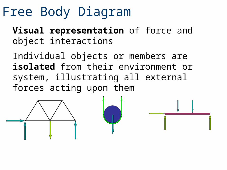
Vector quantity has direction and magnitude
ForceA straight line push or pull acting upon an object
Direction is illustrated by arrowhead
Magnitude is illustrated by length of line segment and is the amount of push or pull
Free Body Diagram Components
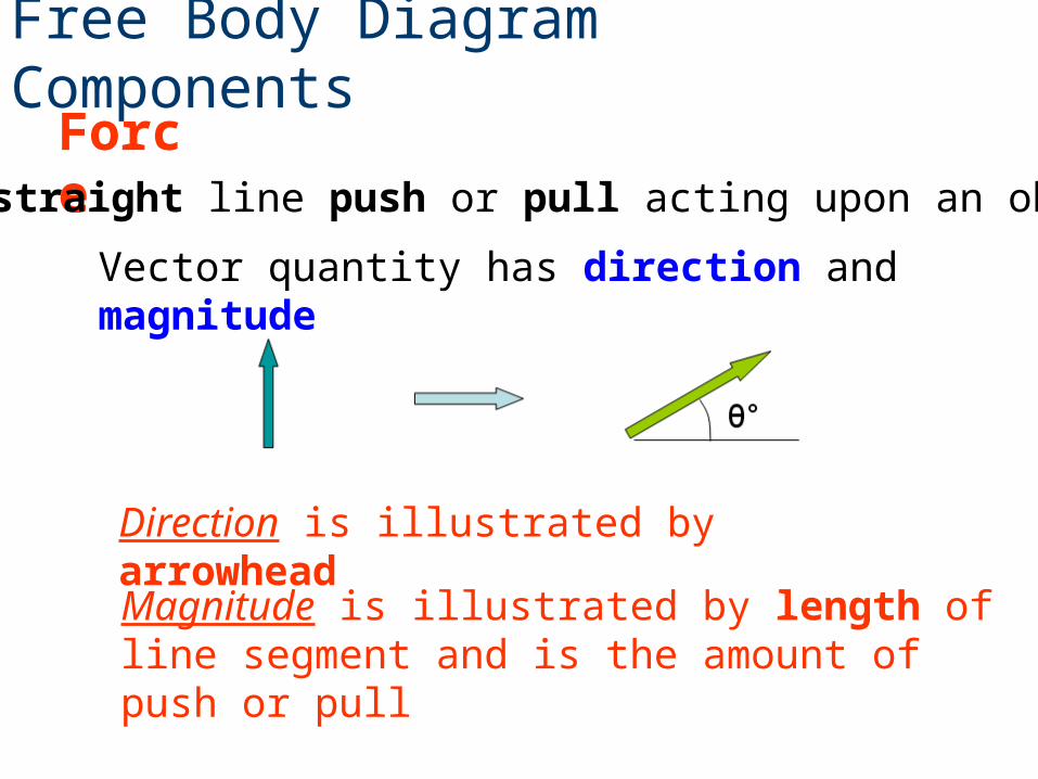
The twisting effort about a point or axis when a force is applied at a distance
Arc with an arrowhead acting about a point indicating direction of CW or CCW
Moment
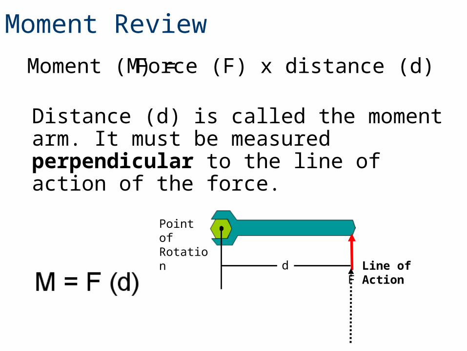
Distance (d) is called the moment arm. It must be measured perpendicular to the line of action of the force.
Moment Review
Line of ActionF
Point of Rotation
d
Moment (M) = Force (F) x distance (d)
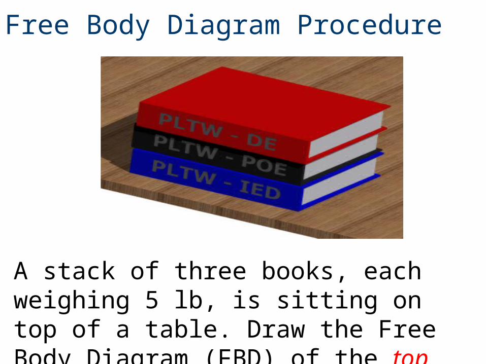
Free Body Diagram Procedure
A stack of three books, each weighing 5 lb, is sitting on top of a table. Draw the Free Body Diagram (FBD) of the top book.
Free Body Diagram Procedure
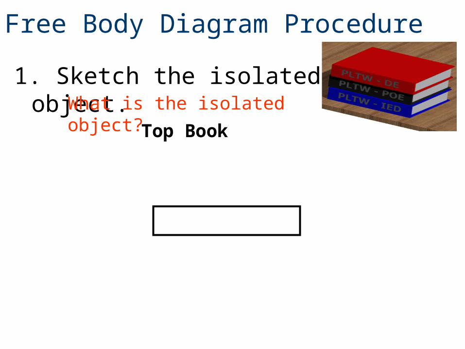
1. Sketch the isolated object.What is the isolated object?
Top Book
Free Body Diagram Procedure
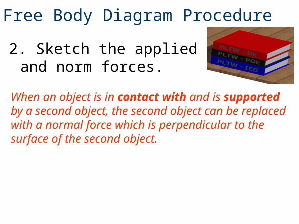
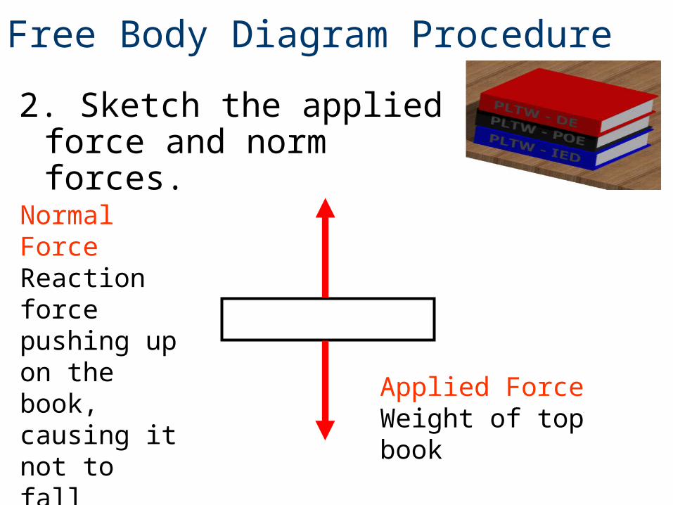
2. Sketch the applied and norm forces.
When an object is in contact with and is supported by a second object, the second object can be replaced with a normal force which is perpendicular to the surface of the second object.
Free Body Diagram Procedure
2. Sketch the applied force and norm forces.
Applied Force Weight of top book
Normal Force Reaction force pushing up on the book, causing it not to fall
Free Body Diagram Procedure
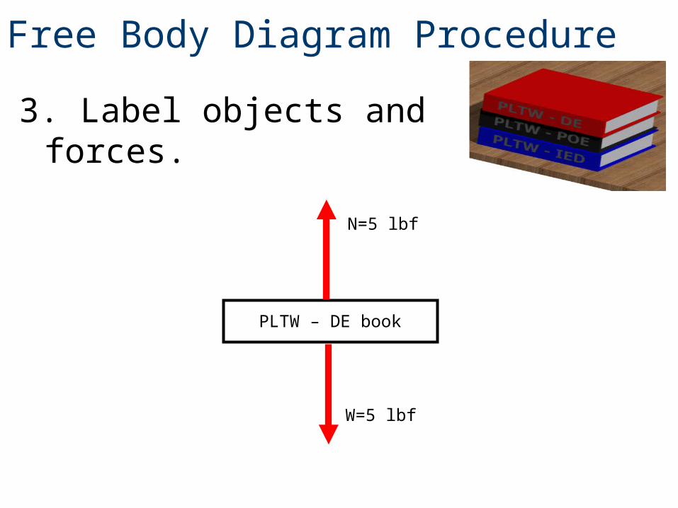
3. Label objects and forces.
N=5 lbf
W=5 lbf
PLTW – DE book
Free Body Diagram Procedure
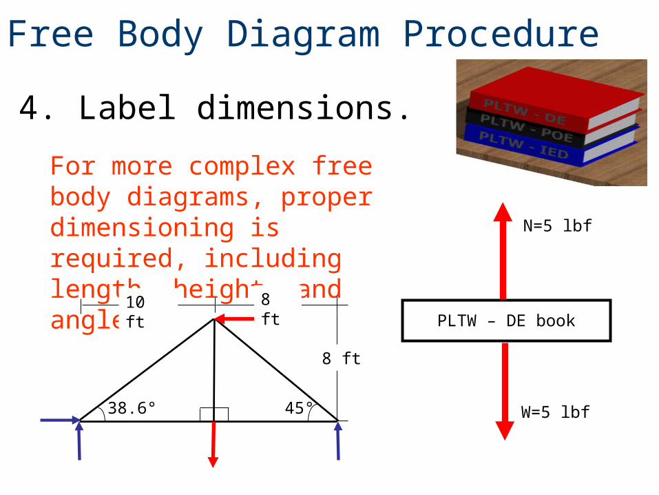
4. Label dimensions.
N=5 lbf
W=5 lbf
PLTW – DE book
For more complex free body diagrams, proper dimensioning is required, including length, height, and angles.
45°
8 ft
8 ft10 ft
38.6°
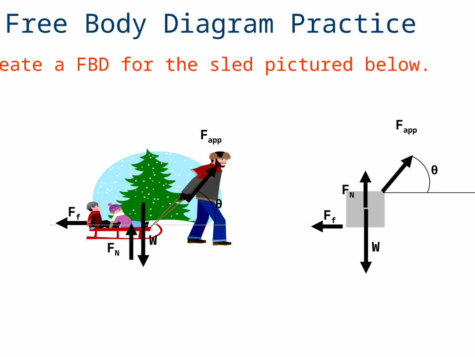
Free Body Diagram Practice
Fapp
FN
W W
Ff
θ
θ
Create a FBD for the sled pictured below.
Fapp
Ff
FN
Free Body Diagram Practice
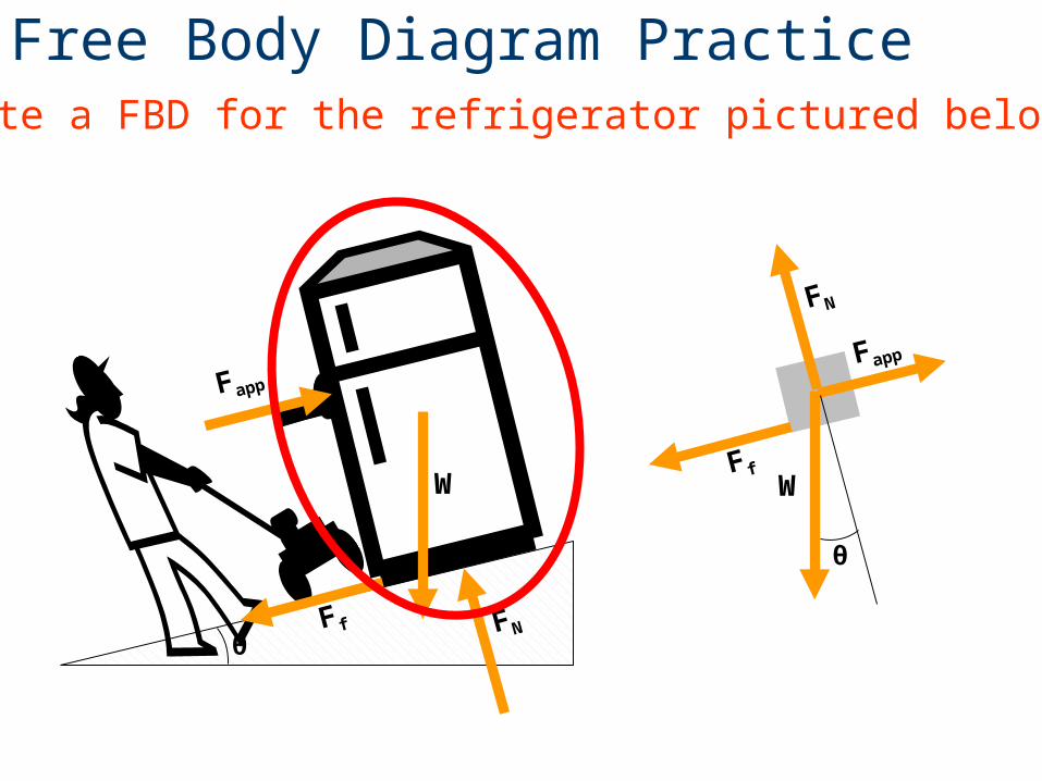
FN
W W
FN
Fapp
Fapp
F f
F f
θ
θ
Create a FBD for the refrigerator pictured below.
Free Body Diagram Practice
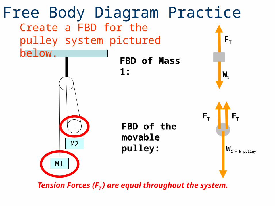
M1
M2
FBD of Mass 1:
FT
FBD of the movable pulley:
W1
W2 + W pulley
FT
FT
Tension Forces (FT ) are equal throughout the system.
Create a FBD for the pulley system pictured below.
Different types of support reactions• Cable, rope, or chain• Pin• Roller• Built-in end – Cantilever
Free Body Diagram Reactions
To aid in completing free body diagrams, connections are often identified with letters.
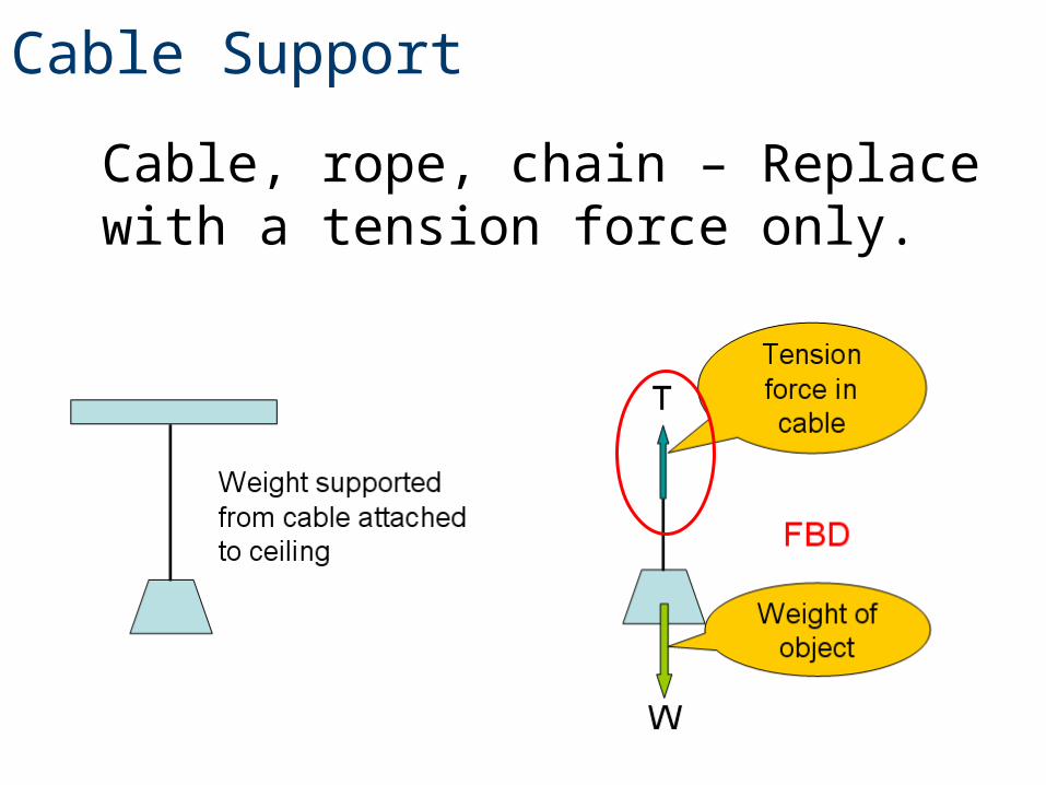
Cable, rope, chain – Replace with a tension force only.
Cable Support
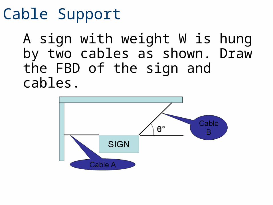
A sign with weight W is hung by two cables as shown. Draw the FBD of the sign and cables.
Cable Support
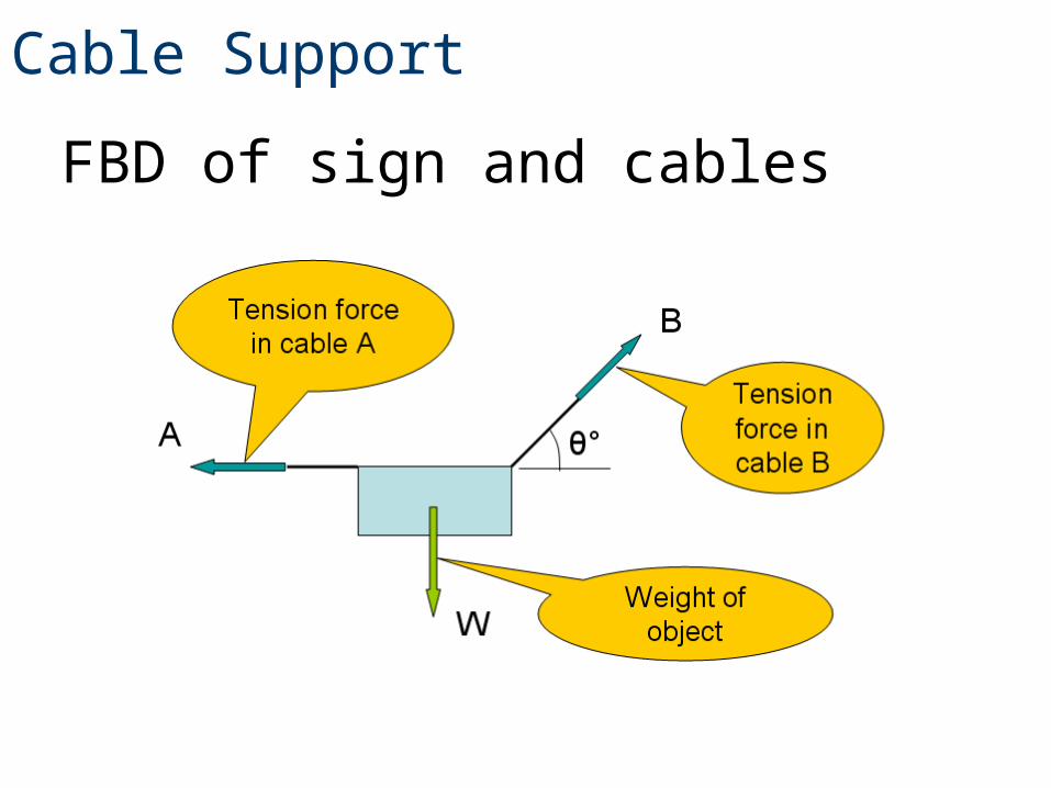
FBD of sign and cables
Cable Support
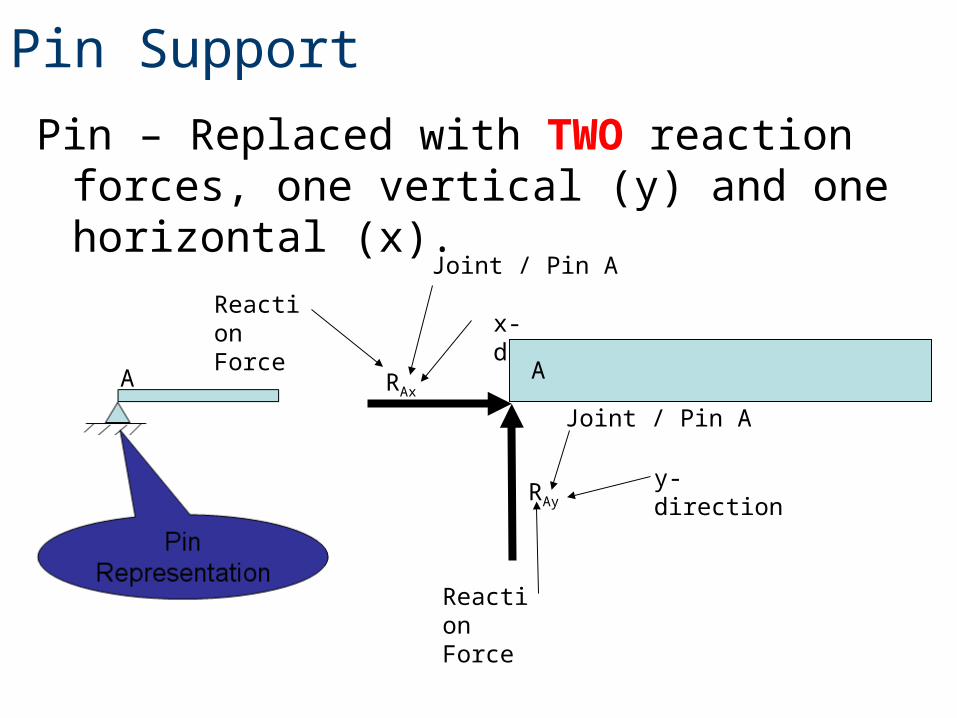
Pin – Replaced with TWO reaction forces, one vertical (y) and one horizontal (x).
Pin Support
A RAx
RAy
Reaction Force
Joint / Pin A
y-direction
Reaction Force
Joint / Pin A
x-direction
A
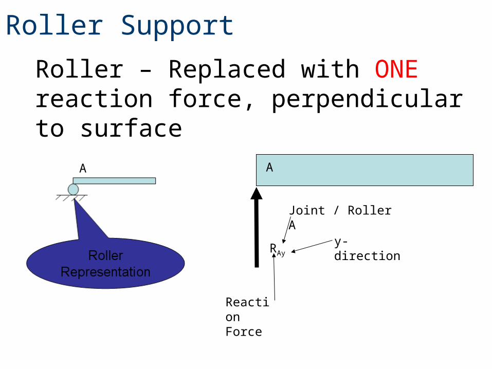
Roller – Replaced with ONE reaction force, perpendicular to surface
Roller Support
A A
RAy
y-direction
Reaction Force
Joint / Roller A
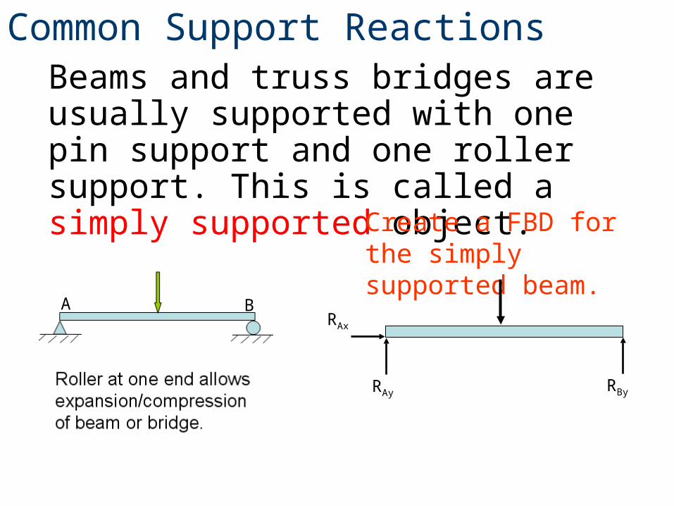
Beams and truss bridges are usually supported with one pin support and one roller support. This is called a simply supported object.
Common Support Reactions
Create a FBD for the simply supported beam.
A BRAx
RAy RBy
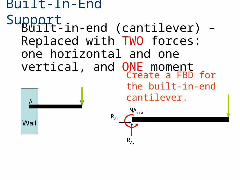
Built-in-end (cantilever) – Replaced with TWO forces: one horizontal and one vertical, and ONE moment
Built-In-End Support
A
RAx
RAy
MAccw
Create a FBD for the built-in-end cantilever.
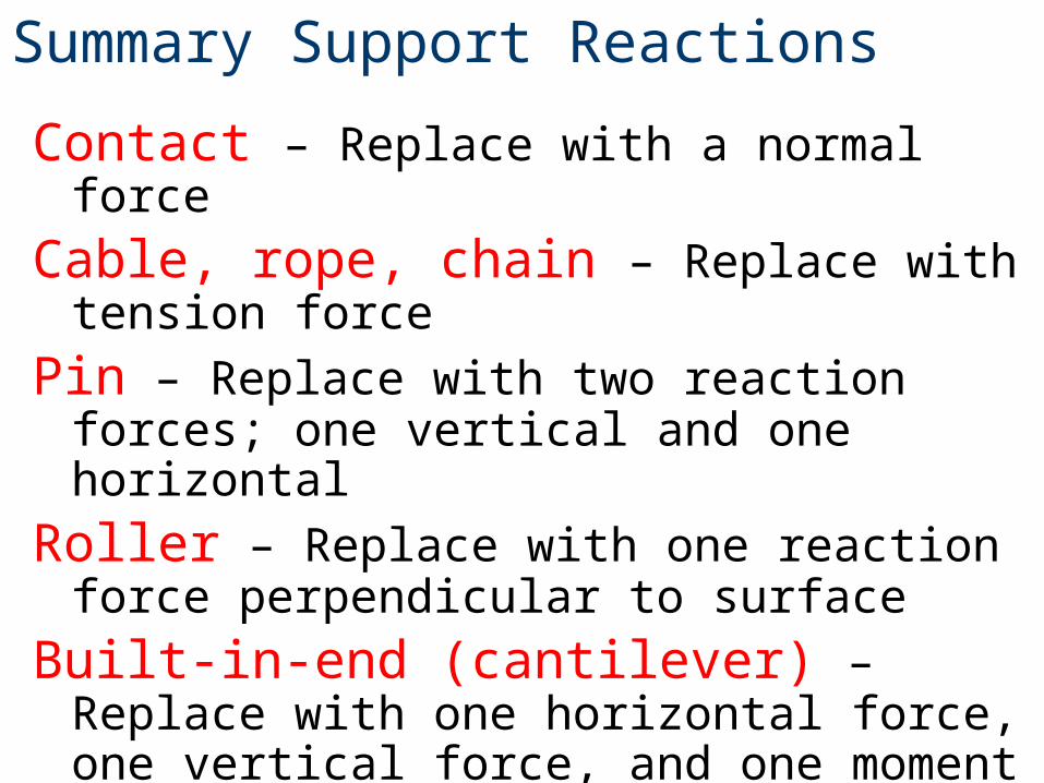
Contact – Replace with a normal force
Cable, rope, chain – Replace with tension force
Pin – Replace with two reaction forces; one vertical and one horizontal
Roller – Replace with one reaction force perpendicular to surface
Built-in-end (cantilever) – Replace with one horizontal force, one vertical force, and one moment
Summary Support Reactions
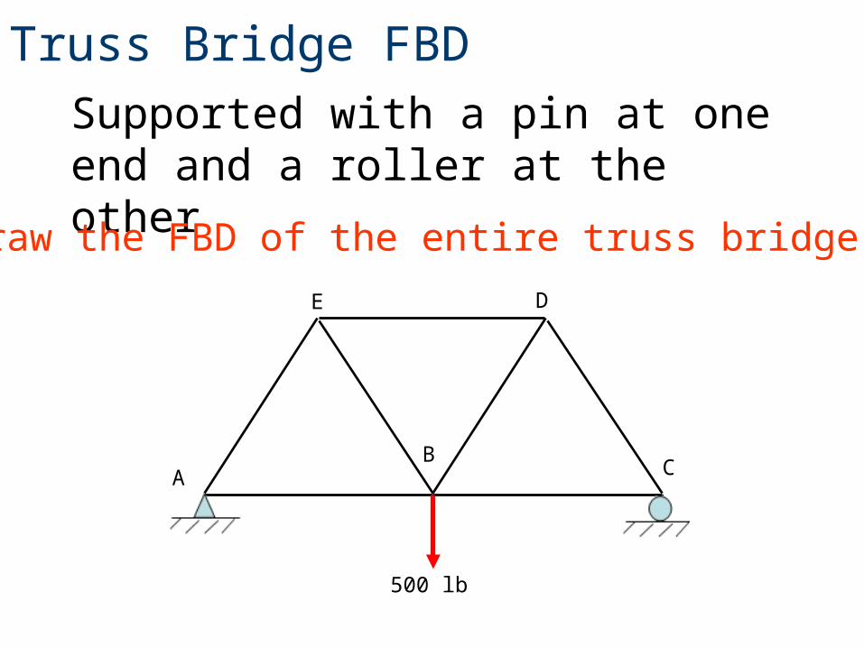
Supported with a pin at one end and a roller at the other
Truss Bridge FBD
Draw the FBD of the entire truss bridge.
AB
C
DE
500 lb
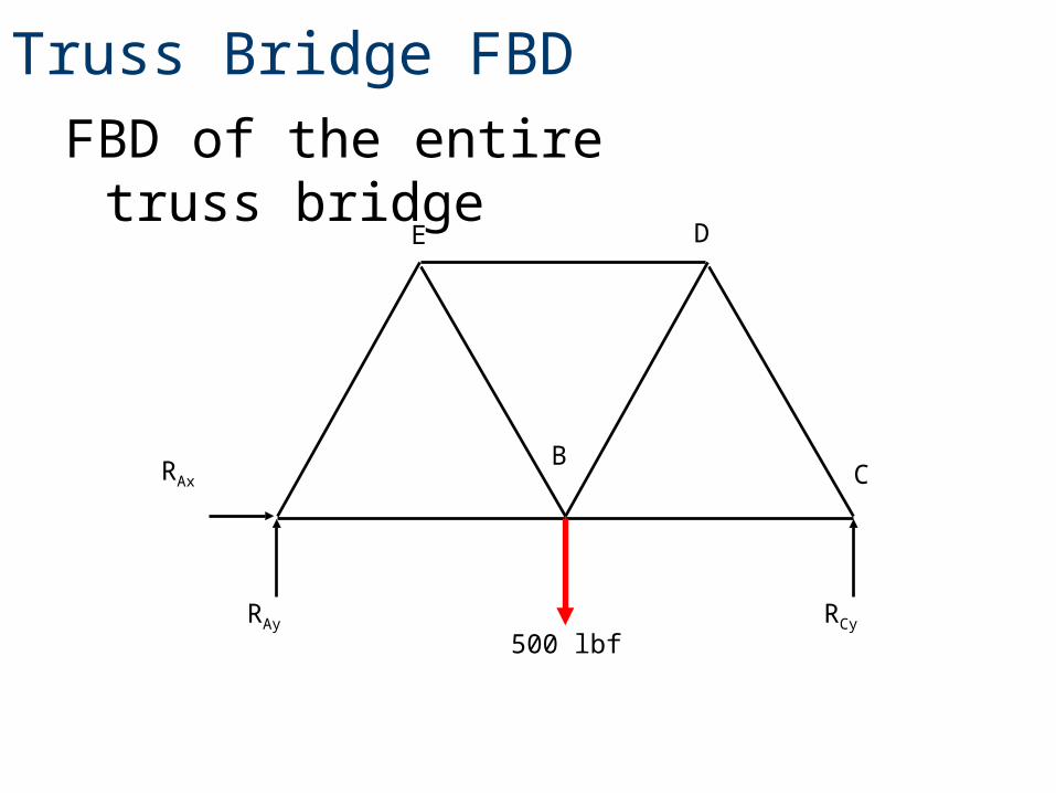
FBD of the entire truss bridge
Truss Bridge FBD
BC
DE
500 lbf
RAx
RAy RCy