Embed Size (px)
Citation preview
Free Body Diagram Exercises
FBD- 1
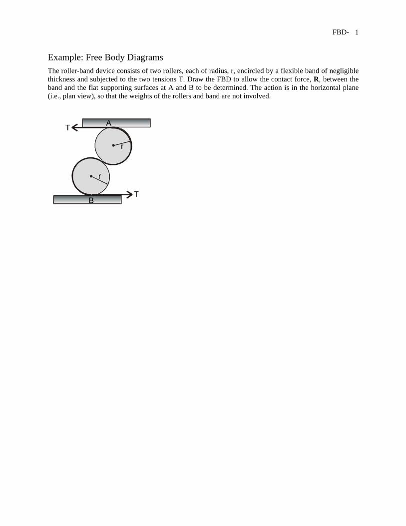
Example: Free Body Diagrams The roller-band device consists of two rollers, each of radius, r, encircled by a flexible band of negligible thickness and subjected to the two tensions T. Draw the FBD to allow the contact force, R, between the band and the flat supporting surfaces at A and B to be determined. The action is in the horizontal plane (i.e., plan view), so that the weights of the rollers and band are not involved.
r
r
T
T A
B
FBD- 2
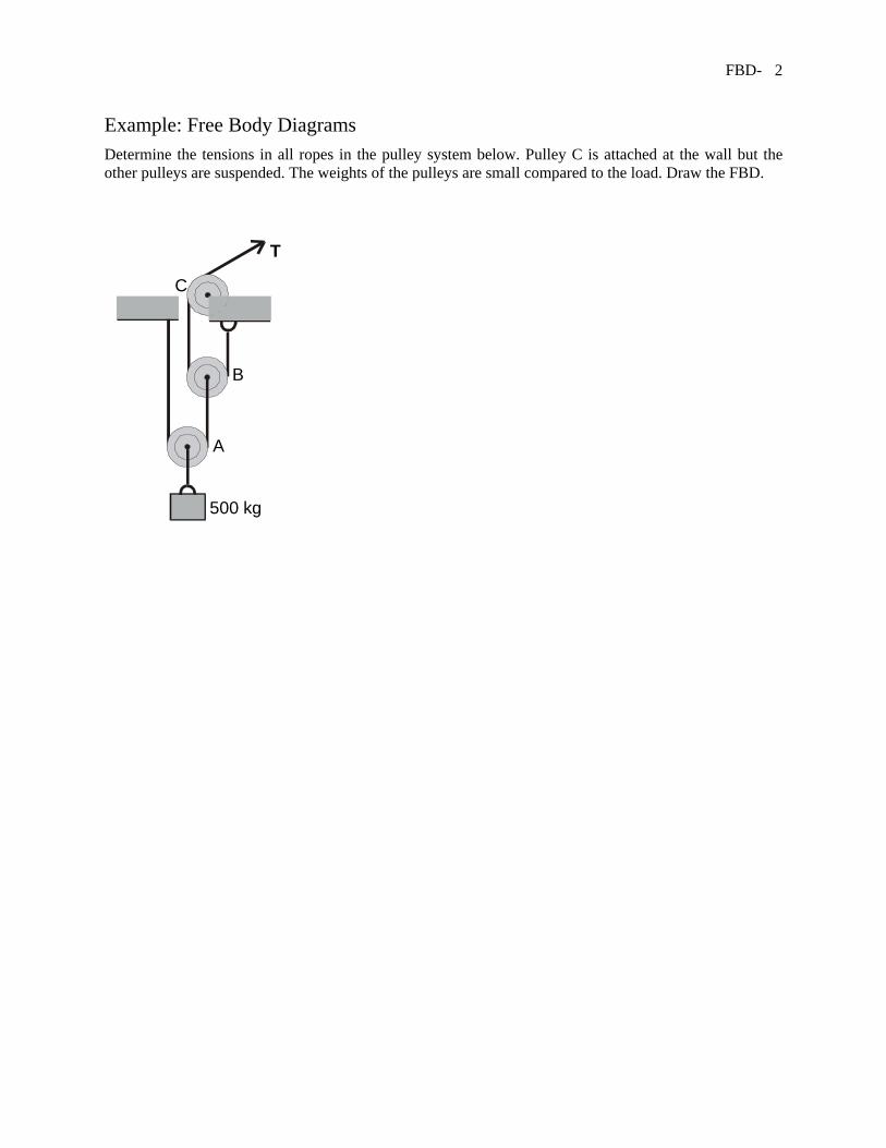
Example: Free Body Diagrams Determine the tensions in all ropes in the pulley system below. Pulley C is attached at the wall but the other pulleys are suspended. The weights of the pulleys are small compared to the load. Draw the FBD.
T
A
B
C
500 kg
FBD- 3
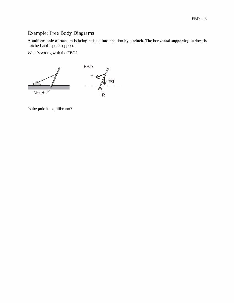
Example: Free Body Diagrams A uniform pole of mass m is being hoisted into position by a winch. The horizontal supporting surface is notched at the pole support.
What’s wrong with the FBD?
Notch
Tmg
R
FBD
Is the pole in equilibrium?
FBD- 4
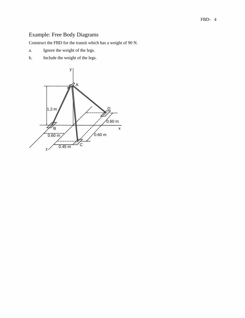
Example: Free Body Diagrams Construct the FBD for the transit which has a weight of 90 N.
a. Ignore the weight of the legs.
b. Include the weight of the legs.
B
0.60 m 0.60 m
0.60 m
0.45 m
x
y
z
D
A
C
1.2 m
FBD- 5
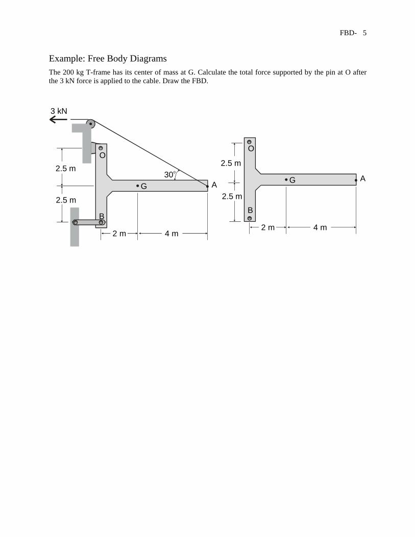
Example: Free Body Diagrams The 200 kg T-frame has its center of mass at G. Calculate the total force supported by the pin at O after the 3 kN force is applied to the cable. Draw the FBD.
4 m2 m
AG
O
B
2.5 m
2.5 m
30o
3 kN
4 m2 m
AG
O
B
2.5 m
2.5 m
FBD- 6
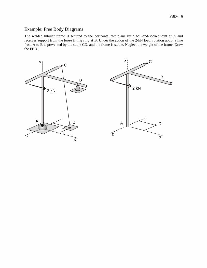
Example: Free Body Diagrams The welded tubular frame is secured to the horizontal x-z plane by a ball-and-socket joint at A and receives support from the loose fitting ring at B. Under the action of the 2-kN load, rotation about a line from A to B is prevented by the cable CD, and the frame is stable. Neglect the weight of the frame. Draw the FBD.
B
2 kN
A D
xz
y C
B
2 kN
A D
xz
yC
FBD- 7
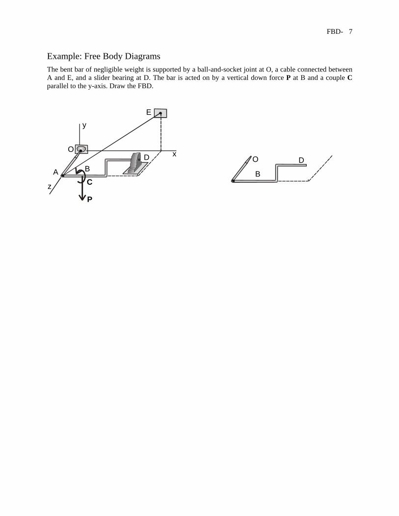
Example: Free Body Diagrams The bent bar of negligible weight is supported by a ball-and-socket joint at O, a cable connected between A and E, and a slider bearing at D. The bar is acted on by a vertical down force P at B and a couple C parallel to the y-axis. Draw the FBD.
x
y
z
A BD
O
E
C
P
B
DO
FBD- 8
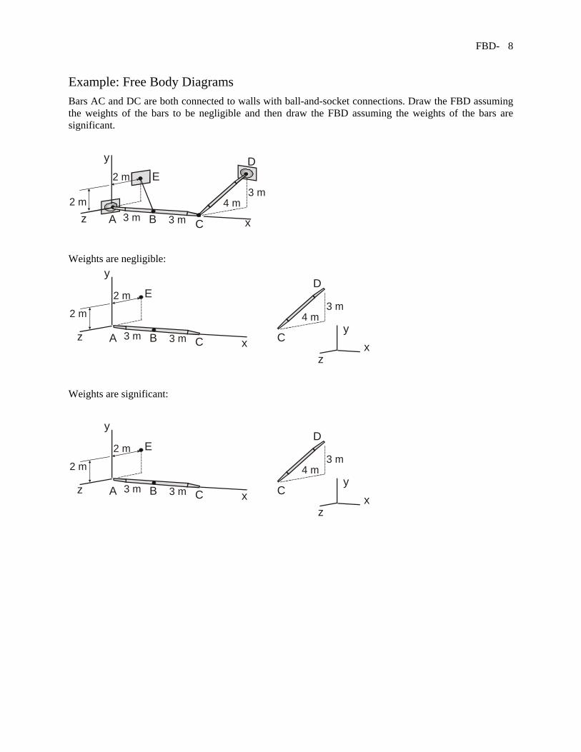
Example: Free Body Diagrams Bars AC and DC are both connected to walls with ball-and-socket connections. Draw the FBD assuming the weights of the bars to be negligible and then draw the FBD assuming the weights of the bars are significant.
y
2 m
3 m 3 m
3 m4 m
A B2 m
D
xz
E
C
Weights are negligible: y
y
2 m
3 m 3 m
3 m4 m
A B
2 m
D
x xz
z
E
C C
Weights are significant:
y
y
2 m
3 m 3 m
3 m4 m
A B
2 m
D
x xz
z
E
C C
FBD- 9
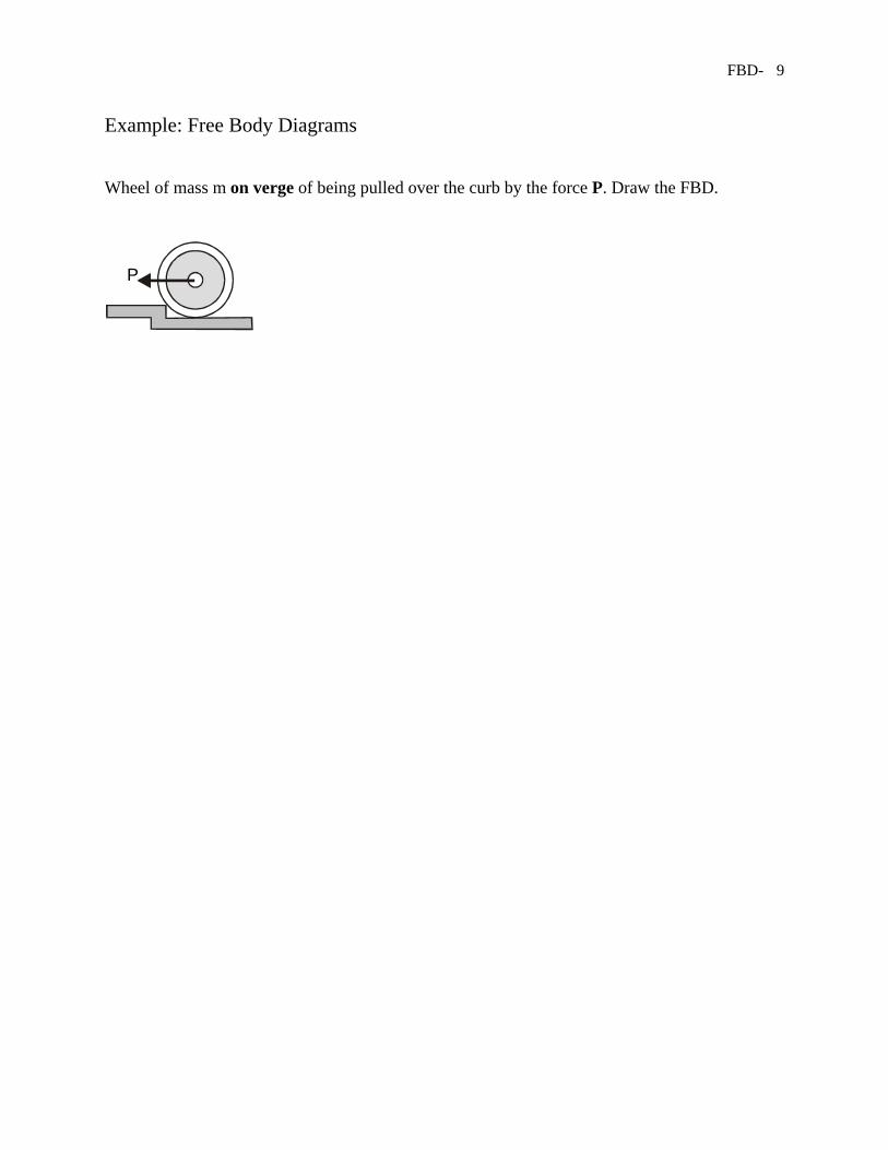
Example: Free Body Diagrams Wheel of mass m on verge of being pulled over the curb by the force P. Draw the FBD.
P
FBD- 10
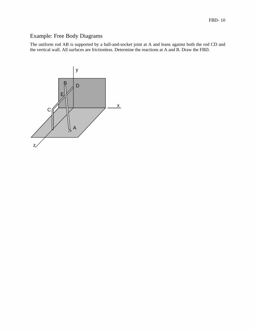
Example: Free Body Diagrams The uniform rod AB is supported by a ball-and-socket joint at A and leans against both the rod CD and the vertical wall. All surfaces are frictionless. Determine the reactions at A and B. Draw the FBD.
x
y
z
B
C
D
E
A
FBD- 11
Example: Free Body Diagrams
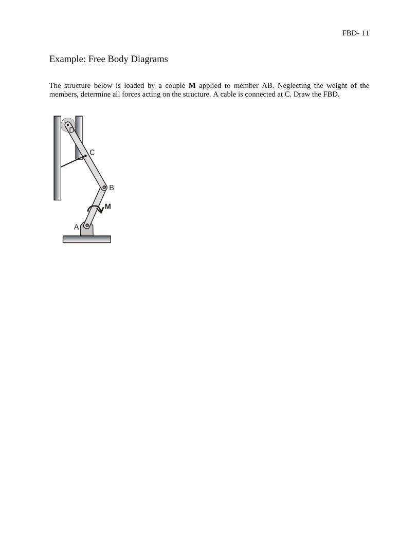
The structure below is loaded by a couple M applied to member AB. Neglecting the weight of the members, determine all forces acting on the structure. A cable is connected at C. Draw the FBD.
A
M
B
C
D
FBD- 12
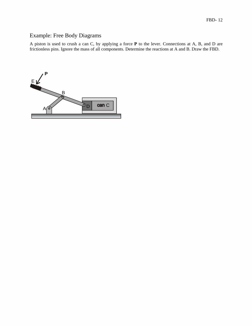
Example: Free Body Diagrams A piston is used to crush a can C, by applying a force P to the lever. Connections at A, B, and D are frictionless pins. Ignore the mass of all components. Determine the reactions at A and B. Draw the FBD.
B
CD
EP
A
FBD- 13
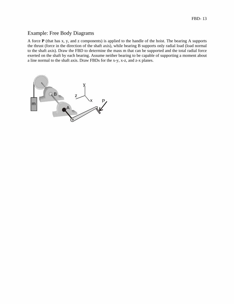
Example: Free Body Diagrams A force P (that has x, y, and z components) is applied to the handle of the hoist. The bearing A supports the thrust (force in the direction of the shaft axis), while bearing B supports only radial load (load normal to the shaft axis). Draw the FBD to determine the mass m that can be supported and the total radial force exerted on the shaft by each bearing. Assume neither bearing to be capable of supporting a moment about a line normal to the shaft axis. Draw FBDs for the x-y, x-z, and z-x planes.
m A
B
Px
y
z
A
B
FBD- 14
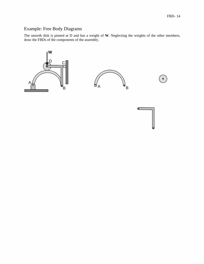
Example: Free Body Diagrams The smooth disk is pinned at D and has a weight of W. Neglecting the weights of the other members, draw the FBDs of the components of the assembly.
AB
CD
W
A B
FBD- 15
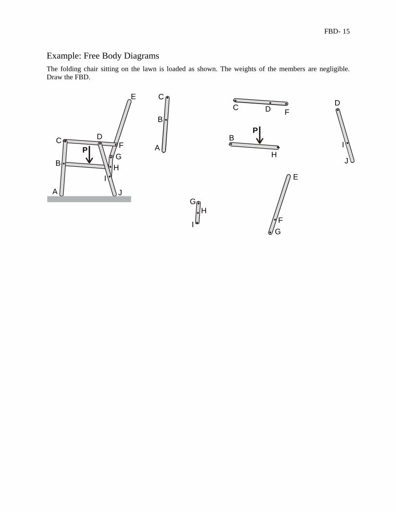
Example: Free Body Diagrams The folding chair sitting on the lawn is loaded as shown. The weights of the members are negligible. Draw the FBD.
P
A
B
C D
E
FG
HI
J
P
AB
BC
CD
D
E
F
F
G
GH
H
I
I
J
FBD- 16
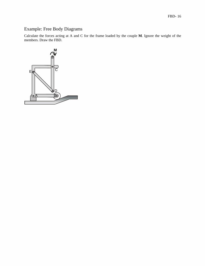
Example: Free Body Diagrams Calculate the forces acting at A and C for the frame loaded by the couple M. Ignore the weight of the members. Draw the FBD.
A B
C
D
E
M
FBD- 17
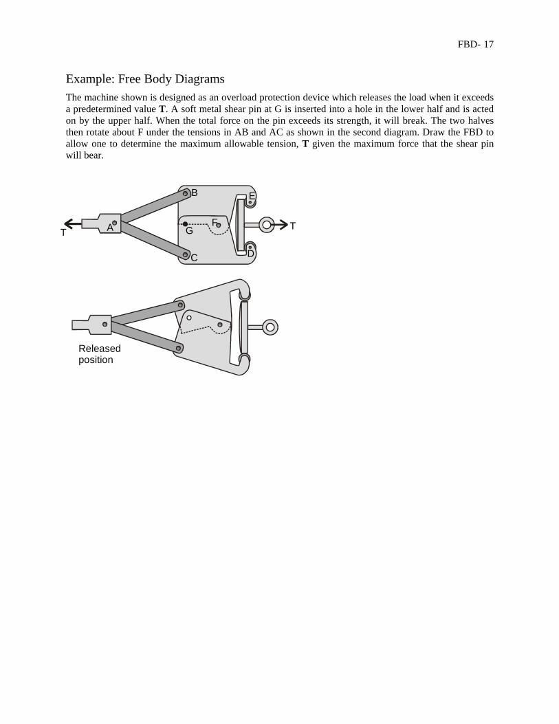
Example: Free Body Diagrams The machine shown is designed as an overload protection device which releases the load when it exceeds a predetermined value T. A soft metal shear pin at G is inserted into a hole in the lower half and is acted on by the upper half. When the total force on the pin exceeds its strength, it will break. The two halves then rotate about F under the tensions in AB and AC as shown in the second diagram. Draw the FBD to allow one to determine the maximum allowable tension, T given the maximum force that the shear pin will bear.
A
B
C D
E
T TFG
Releasedposition
FBD- 18
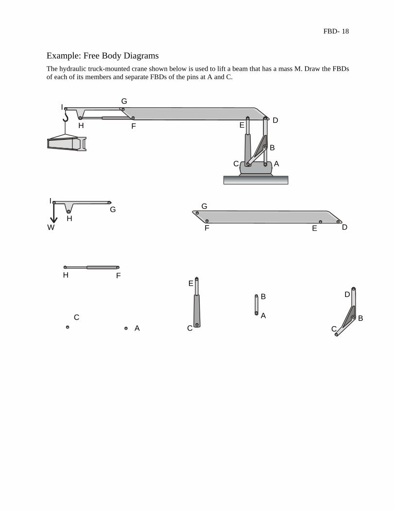
Example: Free Body Diagrams The hydraulic truck-mounted crane shown below is used to lift a beam that has a mass M. Draw the FBDs of each of its members and separate FBDs of the pins at A and C.
A
B
C
DEF
G
H
I
AA
B
BCCC
D
D
E
E
F
F
GG
H
H
I
W
FBD- 19
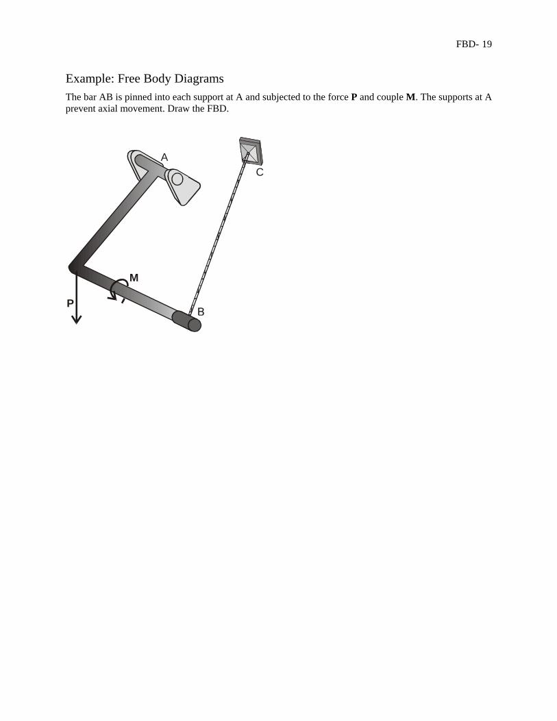
Example: Free Body Diagrams The bar AB is pinned into each support at A and subjected to the force P and couple M. The supports at A prevent axial movement. Draw the FBD.
M
P
A
B
C
FBD- 20
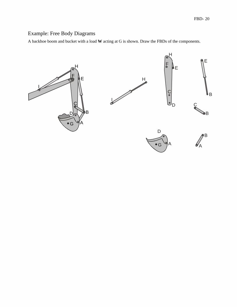
Example: Free Body Diagrams A backhoe boom and bucket with a load W acting at G is shown. Draw the FBDs of the components.
AA
B
B
B
C
C
D
D
EE
F
G
H
H
I
A
B
C
D
EF
G
H
I
FBD- 21
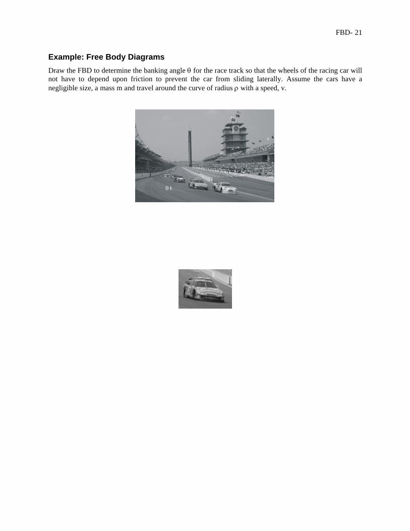
Example: Free Body Diagrams Draw the FBD to determine the banking angle θ for the race track so that the wheels of the racing car will not have to depend upon friction to prevent the car from sliding laterally. Assume the cars have a negligible size, a mass m and travel around the curve of radius ρ with a speed, v.
θ