Embed Size (px)
Citation preview
23chapter
This chapter introduces you to the subject of TV technology. It embodies almostall the principles and circuits covered elsewhere in this book. Studying TV is anexcellent review of communication fundamentals, including modulation and mul-tiplexing, transmitters and receivers, antennas and transmission lines, and evendigital techniques.
This chapter covers the basic NTSC system and TV receiver. The NTSC is theNational Television Standards Committee, the group that developed the standardsfor analog TV and color TV in the 1950s. It also covers cable TV, satellite TV, andthe new digital and high-definition TV systems as defined by the AdvancedTelevision Standards Committee (ATSC).
Objectives
After completing this chapter, you will be able to:
■ Describe and give specifications for a complete TV signal including all itsindividual components.
■ Explain the process used by a TV camera to convert a visual scene to avideo signal.
■ Draw a simplified block diagram, showing main components, of a TV trans-mitter, a TV receiver and the signal flow.
■ Draw a block diagram of a cable TV system.■ Name all the elements of and explain the operation of a cable TV system.■ Explain the operation of a DBS TV receiver.■ Define digital TV (DTV) and high-definition TV (HDTV), and state the basic
specifications of HDTV receivers.
Television
1
2 Chapter 23
23-1 TV SignalA considerable amount of intelligence is contained in a complete TV signal. As a result,the signal occupies a significant amount of spectrum space. As indicated earlier, the TVsignal consists of two main parts: the sound and the picture. But it is far more complexthan that. The sound today is usually stereo, and the picture carries color information aswell as the synchronizing signals that keep the receiver in step with the transmitter.
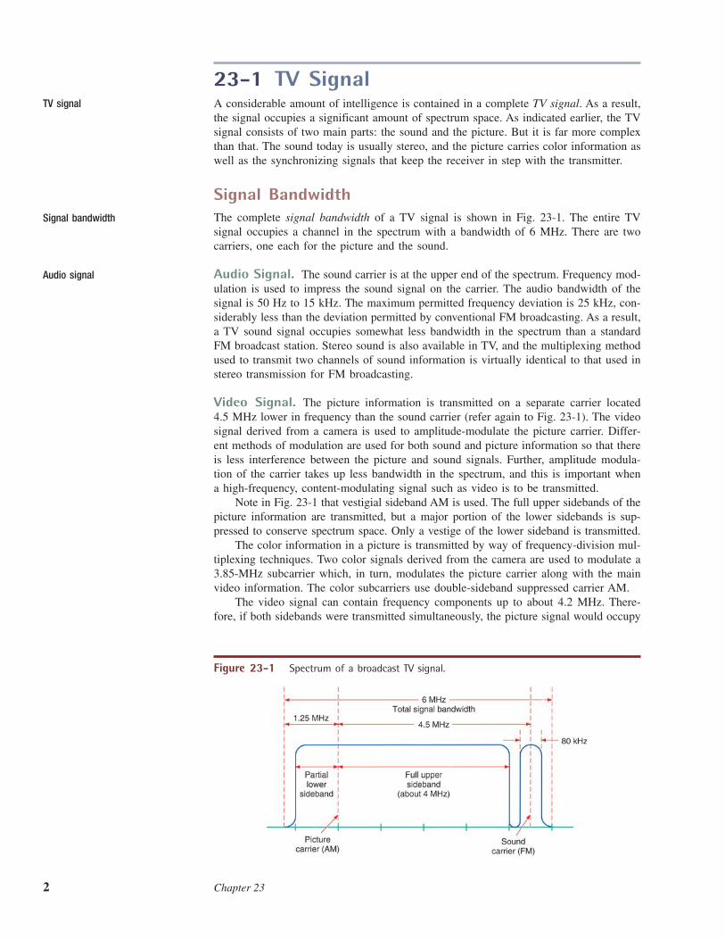
Signal BandwidthThe complete signal bandwidth of a TV signal is shown in Fig. 23-1. The entire TVsignal occupies a channel in the spectrum with a bandwidth of 6 MHz. There are twocarriers, one each for the picture and the sound.
Audio Signal. The sound carrier is at the upper end of the spectrum. Frequency mod-ulation is used to impress the sound signal on the carrier. The audio bandwidth of thesignal is 50 Hz to 15 kHz. The maximum permitted frequency deviation is 25 kHz, con-siderably less than the deviation permitted by conventional FM broadcasting. As a result,a TV sound signal occupies somewhat less bandwidth in the spectrum than a standardFM broadcast station. Stereo sound is also available in TV, and the multiplexing methodused to transmit two channels of sound information is virtually identical to that used instereo transmission for FM broadcasting.
Video Signal. The picture information is transmitted on a separate carrier located4.5 MHz lower in frequency than the sound carrier (refer again to Fig. 23-1). The videosignal derived from a camera is used to amplitude-modulate the picture carrier. Differ-ent methods of modulation are used for both sound and picture information so that thereis less interference between the picture and sound signals. Further, amplitude modula-tion of the carrier takes up less bandwidth in the spectrum, and this is important whena high-frequency, content-modulating signal such as video is to be transmitted.
Note in Fig. 23-1 that vestigial sideband AM is used. The full upper sidebands of thepicture information are transmitted, but a major portion of the lower sidebands is sup-pressed to conserve spectrum space. Only a vestige of the lower sideband is transmitted.
The color information in a picture is transmitted by way of frequency-division mul-tiplexing techniques. Two color signals derived from the camera are used to modulate a3.85-MHz subcarrier which, in turn, modulates the picture carrier along with the mainvideo information. The color subcarriers use double-sideband suppressed carrier AM.
The video signal can contain frequency components up to about 4.2 MHz. There-fore, if both sidebands were transmitted simultaneously, the picture signal would occupy
TV signal
Signal bandwidth
Audio signal
Figure 23-1 Spectrum of a broadcast TV signal.
Television 3
8.4 MHz. The vestigial sideband transmission reduces this excessive bandwidth. The totalbandwidth allocated to a TV signal is 6 MHz.
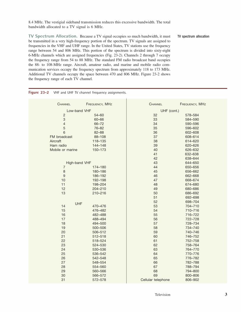
TV Spectrum Allocation. Because a TV signal occupies so much bandwidth, it mustbe transmitted in a very high-frequency portion of the spectrum. TV signals are assigned tofrequencies in the VHF and UHF range. In the United States, TV stations use the frequencyrange between 54 and 806 MHz. This portion of the spectrum is divided into sixty-eight 6-MHz channels which are assigned frequencies (Fig. 23-2). Channels 2 through 7 occupythe frequency range from 54 to 88 MHz. The standard FM radio broadcast band occupiesthe 88- to 108-MHz range. Aircraft, amateur radio, and marine and mobile radio com-munication services occupy the frequency spectrum from approximately 118 to 173 MHz.Additional TV channels occupy the space between 470 and 806 MHz. Figure 23-2 showsthe frequency range of each TV channel.
TV spectrum allocation
CHANNEL FREQUENCY, MHZ CHANNEL FREQUENCY, MHZ
Low-band VHF UHF (cont.)2 54–60 32 578–5843 60–66 33 584–5904 66–72 34 590–5965 76–82 35 596–6026 82–88 36 602–608
FM broadcast 88–108 37 608–614Aircraft 118–135 38 614–620Ham radio 144–148 39 620–626Mobile or marine 150–173 40 626–632
41 632–63842 638–644
High-band VHF 43 644–6507 174–180 44 650–6568 180–186 45 656–6629 186–192 46 662–668
10 192–198 47 668–67411 198–204 48 674–68012 204–210 49 680–68613 210–216 50 686–692
51 692–698
UHF 52 698–70414 470–476 53 704–71015 476–482 54 710–71616 482–488 55 716–72217 488–494 56 722–72818 494–500 57 728–73419 500–506 58 734–74020 506–512 59 740–74621 512–518 60 746–75222 518–524 61 752–75823 524–530 62 758–76424 530–536 63 764–77025 536–542 64 770–77626 542–548 65 776–78227 548–554 66 782–78828 554–560 67 788–79429 560–566 68 794–80030 566–572 69 800–80631 572–578 Cellular telephone 806–902
Figure 23-2 VHF and UHF TV channel frequency assignments.
GOOD TO KNOWIn a TV signal, the sound is
frequency-modulated, and the
picture is amplitude-modulated.
Different methods of modulation
are used to minimize interference
between the picture and sound
signals.
GOOD TO KNOWA given scene is divided into seg-
ments that can be transmitted
serially over a period of time,
because any scene contains so
much light information that it
would be impossible for an
electronic device to perform a
simultaneous conversion of all
of it.
4 Chapter 23
To find the exact frequencies of the transmitter and sound carriers, use Fig. 23-2 andthe spectrum outline in Fig. 23-1. To compute the picture carrier, add 1.25 MHz to thelower frequency of range given in Fig. 23-2. For example, for channel 6, the lower fre-quency is 82 MHz. The picture carrier is or 83.25, MHz. The sound carrieris 4.5 MHz higher, or that is, 87.75, MHz.
It is important to point out that although TV is still transmitted by radio waves, mostviewers get their TV signals via a cable. More than 80 percent of U.S. homes have cableTV that carries the “over-the-air” TV channels as well as premium and specialized chan-nels of programming. In the near future, the FCC will auction off the upper VHF chan-nels (53–69) to other services such as cell phones and wireless LANs and MANs. Somecell phone TVs will use these channels.
Generating the Video SignalThe video signal is most often generated by a TV camera, a very sophisticated electronicdevice that incorporates lenses and light-sensitive transducers to convert the scene orobject to be viewed to an electric signal that can be used to modulate a carrier. All vis-ible scenes and objects are simply light that has been reflected and absorbed and thentransmitted to our eyes. It is the purpose of the camera to take the light intensity andcolor details in a scene and convert them to an electric signal.
To do this, the scene to be transmitted is collected and focused by a lens upon alight-sensitive imaging device. Both vacuum tube and semiconductor devices are usedfor converting the light information in the scene to an electric signal. Some examplesare the vidicon tube and the charge-coupled device (CCD) so widely used in camcordersand all modern TV cameras.
The scene is divided into smaller segments that can be transmitted serially over aperiod of time. Again, it is the job of the camera to subdivide the scene in an orderlymanner so that an acceptable signal is developed. This process is known as scanning.
83.25 � 4.5,82 � 1.25,
Scan lines
Example 23-1Compute the picture and sound carrier frequencies for UHF TV channel 39.
1. From Fig. 23-2, channel 39 extends from 620 to 626 MHz.
2. The picture carrier is 1.25 MHz above the lower band limit, or
3. The sound carrier is 4.5 MHz above the picture carrier:
4.5 � 621.25 � 625.75 MHz
1.25 � 620 � 621.25 MHz
Principles of Scanning. Scanning is a technique that divides a rectangular sceneinto individual lines. The standard TV scene dimensions have an aspect ratio of 4:3; thatis, the scene width is 4 units for every 3 units of height. To create a picture, the scene issubdivided into many fine horizontal lines called scan lines. Each line represents a verynarrow portion of light variations in the scene. The greater the number of scan lines, thehigher the resolution and the greater the detail that can be observed. U.S. TV standardscall for the scene to be divided into a maximum of 525 horizontal lines.
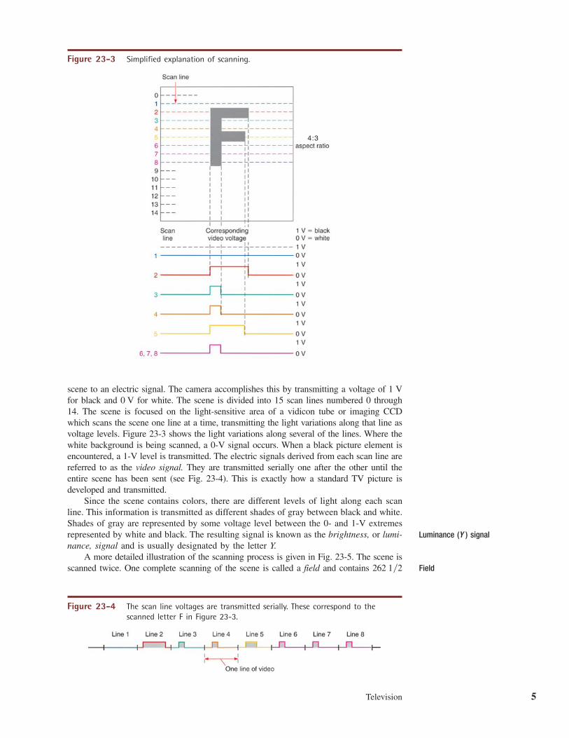
Figure 23-3 is a simplified drawing of the scanning process. In this example, the sceneis a large black letter F on a white background. The task of the TV camera is to convert this
Scanning
Television 5
4 : 3
Figure 23-3 Simplified explanation of scanning.
scene to an electric signal. The camera accomplishes this by transmitting a voltage of 1 Vfor black and 0 V for white. The scene is divided into 15 scan lines numbered 0 through14. The scene is focused on the light-sensitive area of a vidicon tube or imaging CCDwhich scans the scene one line at a time, transmitting the light variations along that line asvoltage levels. Figure 23-3 shows the light variations along several of the lines. Where thewhite background is being scanned, a 0-V signal occurs. When a black picture element isencountered, a 1-V level is transmitted. The electric signals derived from each scan line arereferred to as the video signal. They are transmitted serially one after the other until theentire scene has been sent (see Fig. 23-4). This is exactly how a standard TV picture isdeveloped and transmitted.
Since the scene contains colors, there are different levels of light along each scanline. This information is transmitted as different shades of gray between black and white.Shades of gray are represented by some voltage level between the 0- and 1-V extremesrepresented by white and black. The resulting signal is known as the brightness, or lumi-nance, signal and is usually designated by the letter Y.
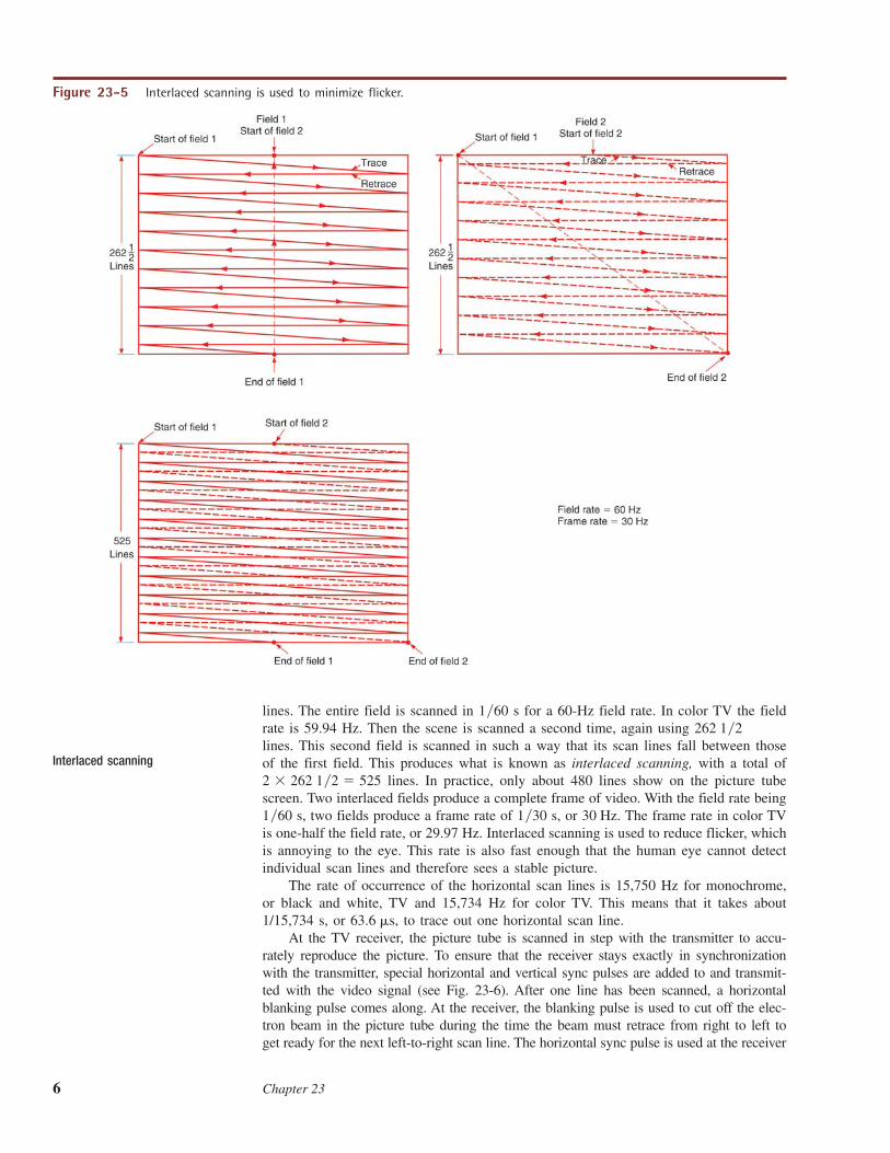
A more detailed illustration of the scanning process is given in Fig. 23-5. The scene isscanned twice. One complete scanning of the scene is called a field and contains 262 1�2
Figure 23-4 The scan line voltages are transmitted serially. These correspond to thescanned letter F in Figure 23-3.
Luminance (Y ) signal
Field
6 Chapter 23
lines. The entire field is scanned in 1�60 s for a 60-Hz field rate. In color TV the fieldrate is 59.94 Hz. Then the scene is scanned a second time, again using 262 1�2lines. This second field is scanned in such a way that its scan lines fall between thoseof the first field. This produces what is known as interlaced scanning, with a total of
1�2 lines. In practice, only about 480 lines show on the picture tubescreen. Two interlaced fields produce a complete frame of video. With the field rate being1�60 s, two fields produce a frame rate of 1�30 s, or 30 Hz. The frame rate in color TVis one-half the field rate, or 29.97 Hz. Interlaced scanning is used to reduce flicker, whichis annoying to the eye. This rate is also fast enough that the human eye cannot detectindividual scan lines and therefore sees a stable picture.
The rate of occurrence of the horizontal scan lines is 15,750 Hz for monochrome,or black and white, TV and 15,734 Hz for color TV. This means that it takes about1/15,734 s, or to trace out one horizontal scan line.
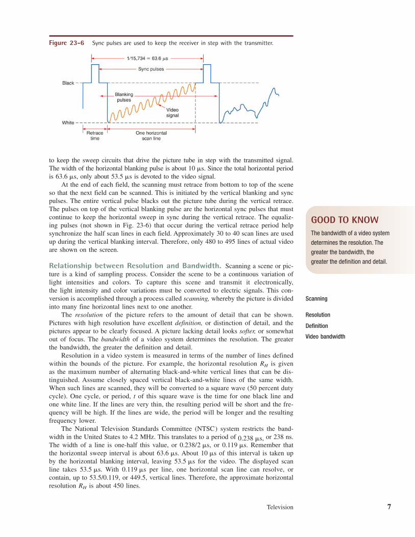
At the TV receiver, the picture tube is scanned in step with the transmitter to accu-rately reproduce the picture. To ensure that the receiver stays exactly in synchronizationwith the transmitter, special horizontal and vertical sync pulses are added to and transmit-ted with the video signal (see Fig. 23-6). After one line has been scanned, a horizontalblanking pulse comes along. At the receiver, the blanking pulse is used to cut off the elec-tron beam in the picture tube during the time the beam must retrace from right to left toget ready for the next left-to-right scan line. The horizontal sync pulse is used at the receiver
63.6 �s,
� 5252 � 262Interlaced scanning
Figure 23-5 Interlaced scanning is used to minimize flicker.
Television 7
to keep the sweep circuits that drive the picture tube in step with the transmitted signal.The width of the horizontal blanking pulse is about Since the total horizontal periodis only about is devoted to the video signal.
At the end of each field, the scanning must retrace from bottom to top of the sceneso that the next field can be scanned. This is initiated by the vertical blanking and syncpulses. The entire vertical pulse blacks out the picture tube during the vertical retrace.The pulses on top of the vertical blanking pulse are the horizontal sync pulses that mustcontinue to keep the horizontal sweep in sync during the vertical retrace. The equaliz-ing pulses (not shown in Fig. 23-6) that occur during the vertical retrace period helpsynchronize the half scan lines in each field. Approximately 30 to 40 scan lines are usedup during the vertical blanking interval. Therefore, only 480 to 495 lines of actual videoare shown on the screen.
Relationship between Resolution and Bandwidth. Scanning a scene or pic-ture is a kind of sampling process. Consider the scene to be a continuous variation oflight intensities and colors. To capture this scene and transmit it electronically, the light intensity and color variations must be converted to electric signals. This con-version is accomplished through a process called scanning, whereby the picture is dividedinto many fine horizontal lines next to one another.
The resolution of the picture refers to the amount of detail that can be shown.Pictures with high resolution have excellent definition, or distinction of detail, and thepictures appear to be clearly focused. A picture lacking detail looks softer, or somewhatout of focus. The bandwidth of a video system determines the resolution. The greaterthe bandwidth, the greater the definition and detail.
Resolution in a video system is measured in terms of the number of lines definedwithin the bounds of the picture. For example, the horizontal resolution is givenas the maximum number of alternating black-and-white vertical lines that can be dis-tinguished. Assume closely spaced vertical black-and-white lines of the same width.When such lines are scanned, they will be converted to a square wave (50 percent dutycycle). One cycle, or period, t of this square wave is the time for one black line andone white line. If the lines are very thin, the resulting period will be short and the fre-quency will be high. If the lines are wide, the period will be longer and the resultingfrequency lower.
The National Television Standards Committee (NTSC) system restricts the band-width in the United States to 4.2 MHz. This translates to a period of or 238 ns.The width of a line is one-half this value, or or Remember thatthe horizontal sweep interval is about About of this interval is taken upby the horizontal blanking interval, leaving for the video. The displayed scanline takes With per line, one horizontal scan line can resolve, orcontain, up to 53.5/0.119, or 449.5, vertical lines. Therefore, the approximate horizontalresolution is about 450 lines.RH
0.119 �s53.5 �s.53.5 �s
10 �s63.6 �s.0.119 �s.0.238/2 �s,
0.238 �s,
RH
53.5 �s63.6 �s,10 �s.
Figure 23-6 Sync pulses are used to keep the receiver in step with the transmitter.
Resolution
Definition
Video bandwidth
Scanning
GOOD TO KNOWThe bandwidth of a video system
determines the resolution. The
greater the bandwidth, the
greater the definition and detail.
8 Chapter 23
The vertical resolution is the number of horizontal lines that can be distinguished.Only about 480 to 495 horizontal lines are shown on the screen. The vertical resolutionis about 0.7 times the number of actual lines :
If 485 lines are shown, the vertical resolution is or 340, lines. In practice,the bandwidth varies as will the horizontal resolution. The lowest is about 340, but itcould be as high as 640. A typical figure is 427.
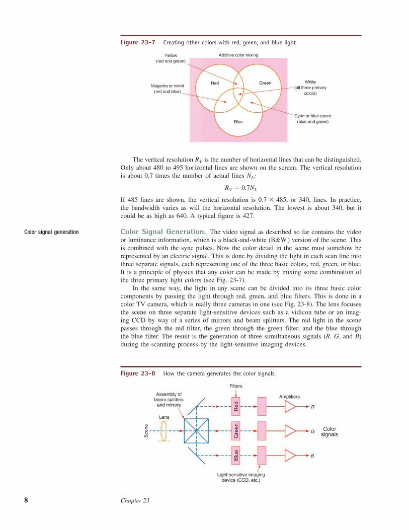
Color Signal Generation. The video signal as described so far contains the videoor luminance information, which is a black-and-white (B&W) version of the scene. Thisis combined with the sync pulses. Now the color detail in the scene must somehow berepresented by an electric signal. This is done by dividing the light in each scan line intothree separate signals, each representing one of the three basic colors, red, green, or blue.It is a principle of physics that any color can be made by mixing some combination ofthe three primary light colors (see Fig. 23-7).
In the same way, the light in any scene can be divided into its three basic colorcomponents by passing the light through red, green, and blue filters. This is done in acolor TV camera, which is really three cameras in one (see Fig. 23-8). The lens focusesthe scene on three separate light-sensitive devices such as a vidicon tube or an imag-ing CCD by way of a series of mirrors and beam splitters. The red light in the scenepasses through the red filter, the green through the green filter, and the blue throughthe blue filter. The result is the generation of three simultaneous signals (R, G, and B)during the scanning process by the light-sensitive imaging devices.
0.7 � 485,
RV � 0.7NL
NL
RV
Figure 23-7 Creating other colors with red, green, and blue light.
Color signal generation
R
G
B
Figure 23-8 How the camera generates the color signals.
Television 9
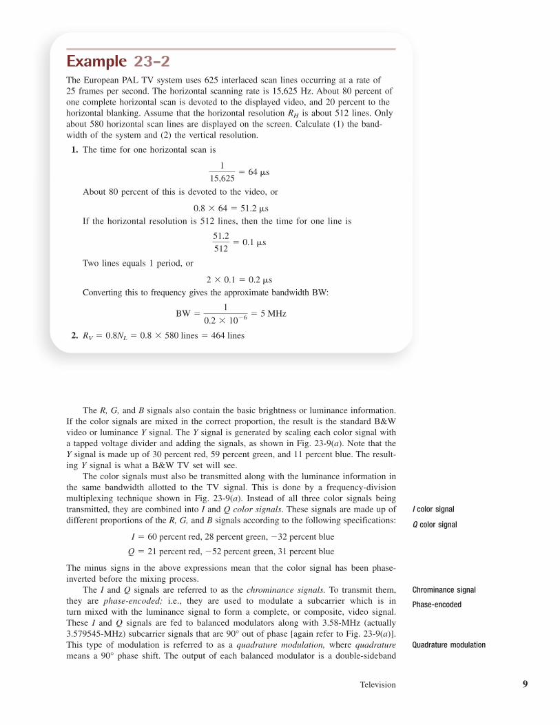
Example 23-2The European PAL TV system uses 625 interlaced scan lines occurring at a rate of25 frames per second. The horizontal scanning rate is 15,625 Hz. About 80 percent ofone complete horizontal scan is devoted to the displayed video, and 20 percent to thehorizontal blanking. Assume that the horizontal resolution is about 512 lines. Onlyabout 580 horizontal scan lines are displayed on the screen. Calculate (1) the band-width of the system and (2) the vertical resolution.
1. The time for one horizontal scan is
About 80 percent of this is devoted to the video, or
If the horizontal resolution is 512 lines, then the time for one line is
Two lines equals 1 period, or
Converting this to frequency gives the approximate bandwidth BW:
2. RV � 0.8NL � 0.8 � 580 lines � 464 lines
BW �1
0.2 � 10�6 � 5 MHz
2 � 0.1 � 0.2 �s
51.2
512� 0.1 �s
0.8 � 64 � 51.2 �s
1
15,625� 64 �s
RH
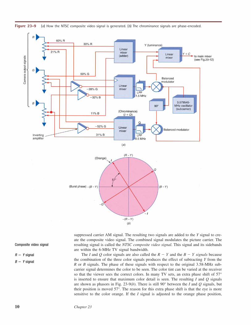
The R, G, and B signals also contain the basic brightness or luminance information.If the color signals are mixed in the correct proportion, the result is the standard B&Wvideo or luminance Y signal. The Y signal is generated by scaling each color signal witha tapped voltage divider and adding the signals, as shown in Fig. 23-9(a). Note that theY signal is made up of 30 percent red, 59 percent green, and 11 percent blue. The result-ing Y signal is what a B&W TV set will see.
The color signals must also be transmitted along with the luminance information inthe same bandwidth allotted to the TV signal. This is done by a frequency-divisionmultiplexing technique shown in Fig. 23-9(a). Instead of all three color signals beingtransmitted, they are combined into I and Q color signals. These signals are made up ofdifferent proportions of the R, G, and B signals according to the following specifications:
The minus signs in the above expressions mean that the color signal has been phase-inverted before the mixing process.
The I and Q signals are referred to as the chrominance signals. To transmit them,they are phase-encoded; i.e., they are used to modulate a subcarrier which is inturn mixed with the luminance signal to form a complete, or composite, video signal.These I and Q signals are fed to balanced modulators along with 3.58-MHz (actually3.579545-MHz) subcarrier signals that are out of phase [again refer to Fig. 23-9(a)].This type of modulation is referred to as a quadrature modulation, where quadraturemeans a phase shift. The output of each balanced modulator is a double-sideband90°
90°
Q � 21 percent red, �52 percent green, 31 percent blue
I � 60 percent red, 28 percent green, �32 percent blueQ color signal
I color signal
Chrominance signal
Phase-encoded
Quadrature modulation
10 Chapter 23
suppressed carrier AM signal. The resulting two signals are added to the Y signal to cre-ate the composite video signal. The combined signal modulates the picture carrier. Theresulting signal is called the NTSC composite video signal. This signal and its sidebandsare within the 6-MHz TV signal bandwidth.
The I and Q color signals are also called the and the signals becausethe combination of the three color signals produces the effect of subtracting Y from theR or B signals. The phase of these signals with respect to the original 3.58-MHz sub-carrier signal determines the color to be seen. The color tint can be varied at the receiverso that the viewer sees the correct colors. In many TV sets, an extra phase shift of 57°is inserted to ensure that maximum color detail is seen. The resulting I and Q signalsare shown as phasors in Fig. 23-9(b). There is still 90° between the I and Q signals, buttheir position is moved 57°. The reason for this extra phase shift is that the eye is moresensitive to the color orange. If the I signal is adjusted to the orange phase position,
B � YR � Y
G
R
B
Y C
20
QI
(R – Y )
−(R – Y )
−Q
– I
I
Q
−(B – Y ) (B – Y )
Figure 23-9 (a) How the NTSC composite video signal is generated. (b) The chrominance signals are phase-encoded.
R � Y signal
Composite video signal
B � Y signal
Television 11
3.58-MHz suppressed subcarrier
80 kHz
6 MHzTotal signal bandwidth
1.25 MHz4.5 MHz
Picturecarrier (AM)
Soundcarrier (FM)
Total video bandwidth
Bandwidth of I and Q signals1.5 MHz
0.5 MHz
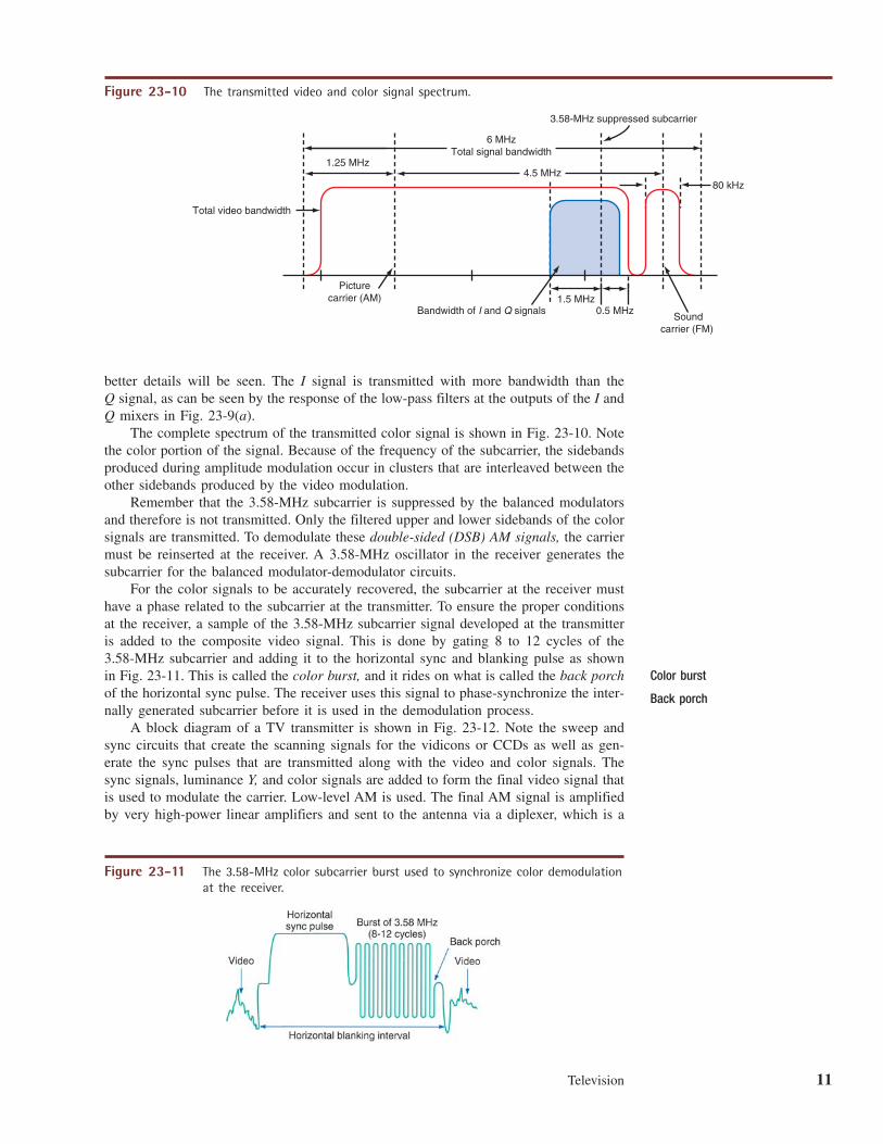
Figure 23-10 The transmitted video and color signal spectrum.
better details will be seen. The I signal is transmitted with more bandwidth than theQ signal, as can be seen by the response of the low-pass filters at the outputs of the I andQ mixers in Fig. 23-9(a).
The complete spectrum of the transmitted color signal is shown in Fig. 23-10. Notethe color portion of the signal. Because of the frequency of the subcarrier, the sidebandsproduced during amplitude modulation occur in clusters that are interleaved between theother sidebands produced by the video modulation.
Remember that the 3.58-MHz subcarrier is suppressed by the balanced modulatorsand therefore is not transmitted. Only the filtered upper and lower sidebands of the colorsignals are transmitted. To demodulate these double-sided (DSB) AM signals, the carriermust be reinserted at the receiver. A 3.58-MHz oscillator in the receiver generates thesubcarrier for the balanced modulator-demodulator circuits.
For the color signals to be accurately recovered, the subcarrier at the receiver musthave a phase related to the subcarrier at the transmitter. To ensure the proper conditionsat the receiver, a sample of the 3.58-MHz subcarrier signal developed at the transmitteris added to the composite video signal. This is done by gating 8 to 12 cycles of the3.58-MHz subcarrier and adding it to the horizontal sync and blanking pulse as shownin Fig. 23-11. This is called the color burst, and it rides on what is called the back porchof the horizontal sync pulse. The receiver uses this signal to phase-synchronize the inter-nally generated subcarrier before it is used in the demodulation process.
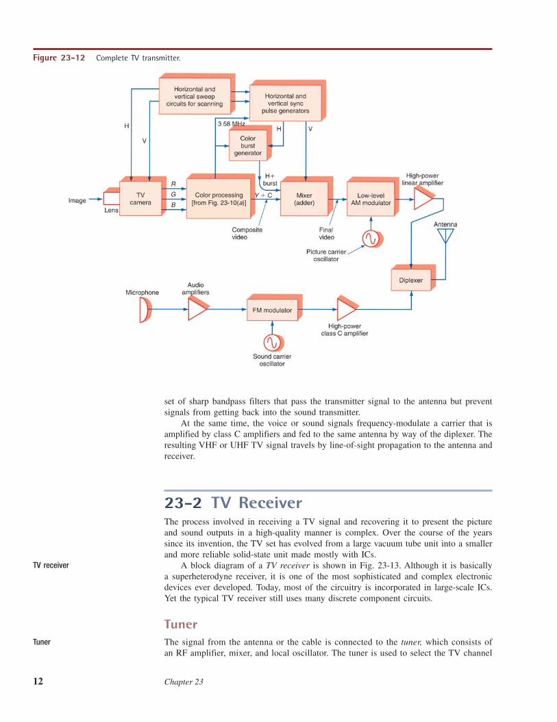
A block diagram of a TV transmitter is shown in Fig. 23-12. Note the sweep andsync circuits that create the scanning signals for the vidicons or CCDs as well as gen-erate the sync pulses that are transmitted along with the video and color signals. Thesync signals, luminance Y, and color signals are added to form the final video signal thatis used to modulate the carrier. Low-level AM is used. The final AM signal is amplifiedby very high-power linear amplifiers and sent to the antenna via a diplexer, which is a
Figure 23-11 The 3.58-MHz color subcarrier burst used to synchronize color demodulationat the receiver.
Color burst
Back porch
12 Chapter 23
set of sharp bandpass filters that pass the transmitter signal to the antenna but preventsignals from getting back into the sound transmitter.
At the same time, the voice or sound signals frequency-modulate a carrier that isamplified by class C amplifiers and fed to the same antenna by way of the diplexer. Theresulting VHF or UHF TV signal travels by line-of-sight propagation to the antenna andreceiver.
23-2 TV ReceiverThe process involved in receiving a TV signal and recovering it to present the pictureand sound outputs in a high-quality manner is complex. Over the course of the yearssince its invention, the TV set has evolved from a large vacuum tube unit into a smallerand more reliable solid-state unit made mostly with ICs.
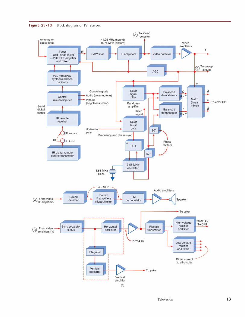
A block diagram of a TV receiver is shown in Fig. 23-13. Although it is basicallya superheterodyne receiver, it is one of the most sophisticated and complex electronicdevices ever developed. Today, most of the circuitry is incorporated in large-scale ICs.Yet the typical TV receiver still uses many discrete component circuits.
TunerThe signal from the antenna or the cable is connected to the tuner, which consists ofan RF amplifier, mixer, and local oscillator. The tuner is used to select the TV channel
Y
R
G
B
Color processing [from Fig. 23-10(a)]
Figure 23-12 Complete TV transmitter.
TV receiver
Tuner
Television 13
R
Y
G
B
R – Y
B – Y
Hz
�
Figure 23-13 Block diagram of TV receiver.
14 Chapter 23
to be viewed and to convert the picture and sound carriers plus their modulation to anintermediate frequency (IF). As in most superheterodyne receivers, the local-oscillatorfrequency is set higher than the incoming signal by the IF value.
Most TV set tuners are prepackaged in sealed and shielded enclosures. They are twotuners in one, one for the VHF signals and another for the UHF signals. The VHF tunerusually uses low-noise FETs for the RF amplifier and the mixer. UHF tuners use a diodemixer with no RF amplifier or a GaAs FET RF amplifier and mixer. Today most moderntuners are a single integrated circuit.
Tuning Synthesizer. The local oscillators are phase-locked loop (PLL) frequencysynthesizers set to frequencies that will convert the TV signals to the IF. Tuning ofthe local oscillator is typically done digitally. The PLL synthesizer is tuned by settingthe feedback frequency-division ratio. In a TV set this is changed by a microproces-sor that is part of the master control system. The interstage LC-resonant circuits inthe tuner are controlled by varactor diodes. By varying the dc bias on the varactors,their capacitance is changed, thereby changing the resonant frequency of the tunedcircuits. The bias control signals also come from the control microprocessor. MostTV sets are tuned by IR remote control. In single-chip tuners, the synthesizer is partof the circuit.
Video Intermediate Frequency and DemodulationThe standard TV receiver IFs are 41.25 MHz for the sound and 45.75 MHz for thepicture. For example, if a receiver is tuned to channel 4, the picture carrier is 67.25 MHz,and the sound carrier is 71.75 MHz (the difference is 4.5 MHz). The synthesizer localoscillator is set to 113 MHz. The tuner produces an output that is the difference betweenthe incoming signal and local-oscillator frequencies, or or 45.75 MHz,for the picture and or 41.25 MHz, for the sound. Because the local-oscillator frequency is above the frequency of incoming signals, the relationship of thepicture and sound carriers is reversed at the intermediate frequencies, the picture IF being4.5 MHz above the sound IF.
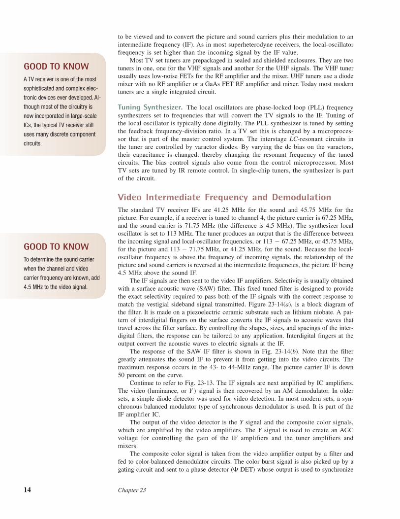
The IF signals are then sent to the video IF amplifiers. Selectivity is usually obtainedwith a surface acoustic wave (SAW) filter. This fixed tuned filter is designed to providethe exact selectivity required to pass both of the IF signals with the correct response tomatch the vestigial sideband signal transmitted. Figure 23-14(a), is a block diagram ofthe filter. It is made on a piezoelectric ceramic substrate such as lithium niobate. A pat-tern of interdigital fingers on the surface converts the IF signals to acoustic waves thattravel across the filter surface. By controlling the shapes, sizes, and spacings of the inter-digital filters, the response can be tailored to any application. Interdigital fingers at theoutput convert the acoustic waves to electric signals at the IF.
The response of the SAW IF filter is shown in Fig. 23-14(b). Note that the filtergreatly attenuates the sound IF to prevent it from getting into the video circuits. Themaximum response occurs in the 43- to 44-MHz range. The picture carrier IF is down50 percent on the curve.
Continue to refer to Fig. 23-13. The IF signals are next amplified by IC amplifiers.The video (luminance, or Y ) signal is then recovered by an AM demodulator. In oldersets, a simple diode detector was used for video detection. In most modern sets, a syn-chronous balanced modulator type of synchronous demodulator is used. It is part of theIF amplifier IC.
The output of the video detector is the Y signal and the composite color signals,which are amplified by the video amplifiers. The Y signal is used to create an AGCvoltage for controlling the gain of the IF amplifiers and the tuner amplifiers andmixers.
The composite color signal is taken from the video amplifier output by a filter andfed to color-balanced demodulator circuits. The color burst signal is also picked up by agating circuit and sent to a phase detector (� DET) whose output is used to synchronize
113 � 71.75 MHz,113 � 67.25 MHz,
GOOD TO KNOWA TV receiver is one of the most
sophisticated and complex elec-
tronic devices ever developed. Al-
though most of the circuitry is
now incorporated in large-scale
ICs, the typical TV receiver still
uses many discrete component
circuits.
GOOD TO KNOWTo determine the sound carrier
when the channel and video
carrier frequency are known, add
4.5 MHz to the video signal.
Television 15
Figure 23-14 (a) Surface acoustic wave (SAW) filter. (b) Typical IF response curve.
an oscillator that produces a 3.58-MHz subcarrier signal of the correct frequency andphase. The output of this oscillator is fed to two balanced demodulators that recover theI and Q signals. The carriers fed to the two balanced modulators are 90° out of phase.Note the 57° phase shifter used to correctly position the color phase for maximum recov-ery of color detail. The Q and I signals are combined in matrix with the Y signal, andout come the three R, G, and B color signals. These are amplified and sent to the pic-ture tube, which reproduces the picture.
Sound Intermediate Frequency and DemodulationTo recover the sound part of the TV signal, a separate sound IF and detector section areused. Continuing to refer to Fig. 23-13, note that the 41.25- and 45.75-MHz sound andpicture IF signals are fed to a sound detector circuit. This is a nonlinear circuit that het-erodynes the two IFs and generates the sum and difference frequencies. The result is a4.5-MHz difference signal that contains both the AM picture and the FM sound modu-lation. This is the sound IF signal. It is passed to the sound IF amplifiers, which alsoperform a clipping-limiting function that removes the AM, leaving only the FM sound.The audio is recovered with a quadrature detector or differential peak detector, asdescribed in Chap. 6. The audio is amplified by one or more audio stages and sent tothe speaker. If stereo is used, the appropriate demultiplexing is done by an IC, and theleft and right channel audio signals are amplified.
Synchronizing CircuitsA major part of the TV receiver is dedicated to the sweep and synchronizing functionsthat are unique to TV receivers. In other words, the receiver’s job does not end withdemodulation and recovery of the picture and sound. To display the picture on a pic-ture tube, special sweep circuits are needed to generate the voltages and currents to
Sound intermediate frequency
Synchronizing circuits
16 Chapter 23
operate the picture tube, and sync circuits are needed to keep the sweep in step withthe transmitted signal.
The sweep and sync operations begin in the video amplifier. The demodulated videoincludes the vertical and horizontal blanking and sync pulses. The sync pulses arestripped off the video signal with a sync separator circuit and fed to the sweep circuits(refer to the lower part of Fig. 23-13). The horizontal sync pulses are used to synchro-nize a horizontal oscillator to 15,734 Hz. This oscillator drives a horizontal output stagethat develops a sawtooth of current that drives magnetic deflection coils in the picturetube yoke that sweep the electron beams in the picture tube.
The horizontal output stage, which is a high-power transistor switch, is also part ofa switching power supply. The horizontal output transistor drives a step up–step downtransformer called the flyback. The 15.734-kHz pulses developed are stepped up, recti-fied, and filtered to develop the 30- to 35-kV-high direct current required to operate thepicture tube. Step-down windings on the flyback produce lower-voltage pulses that arerectified and filtered into low voltages that are used as power supplies for most of thecircuits in the receiver.
The sync pulses are also fed to an IC that takes the horizontal sync pulses duringthe vertical blanking interval and integrates them into a 60-Hz sync pulse which is usedto synchronize a vertical sweep oscillator. The output from this oscillator is a sawtoothsweep voltage at the field rate of 60 Hz (actually 59.94 Hz). This output is amplifiedand converted to a linear sweep current that drives the magnetic coils in the picture tubeyoke. These coils produce vertical deflection of the electron beams in the picture tube.
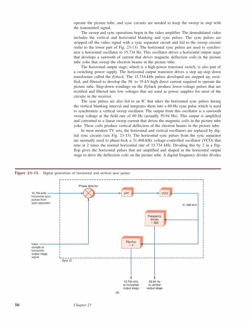
In most modern TV sets, the horizontal and vertical oscillators are replaced by dig-ital sync circuits (see Fig. 23-15). The horizontal sync pulses from the sync separatorare normally used to phase-lock a 31.468-kHz voltage-controlled oscillator (VCO) thatruns at 2 times the normal horizontal rate of 15.734 kHz. Dividing this by 2 in a flip-flop gives the horizontal pulses that are amplified and shaped in the horizontal outputstage to drive the deflection coils on the picture tube. A digital frequency divider divides
Figure 23-15 Digital generation of horizontal and vertical sync pulses.
Television 17
the 31.468-kHz signal by 525 to get a 59.94-Hz signal for vertical sync. This signal isshaped into a current sawtooth and amplified by the vertical output stage which drivesthe deflection coils on the picture tube.
Picture TubeA picture tube is a vacuum tube called a cathode-ray tube (CRT ). Both monochrome(B&W) and color picture tubes are available. The CRT used in computer video moni-tors works as the TV picture tube described here.
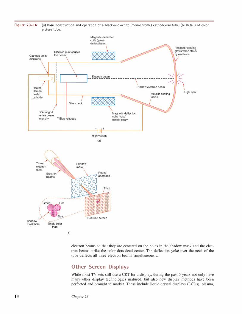
Monochrome CRT. The basic operation of a CRT is illustrated with a monochrometube, as shown in Fig. 23-16(a). The tube is housed in a bell-shaped glass enclosure. Afilament heats a cathode which emits electrons. The negatively charged electrons areattracted and accelerated by positive-bias voltages on the elements in an electron gunassembly. The electron gun also focuses the electrons into a very narrow beam. A con-trol grid that is made negative with respect to the cathode controls the intensity of theelectron beam and the brightness of the spot it makes.
The beam is accelerated forward by a very high voltage applied to an internalmetallic coating called aquadag. The face, or front, of the picture tube is coated inter-nally with a phosphor that glows and produces white light when it is struck by theelectron beam.
Around the neck of the picture tube is a structure of magnetic coils called thedeflection yoke. The horizontal and vertical current linear sawtooth waves generated bythe sweep and synchronizing circuits are applied to the yoke coils, which produce mag-netic fields inside the tube that influence the position of the electron beam. Whenelectrons flow, a magnetic field is produced around the conductor through which thecurrent flows. The magnetic field that occurs around the electron beam is moved ordeflected by the magnetic field produced by the deflection coils in the yoke. Thus theelectron beam is swept across the face of the picture tube in the interlaced mannerdescribed earlier.
As the beam is being swept across the face of the tube to trace out the scene, theintensity of the electron beam is varied by the luminance, or Y, signal, which is appliedto the cathode or in some cases to the control grid. The control grid is an element in theelectron gun that is negatively biased with respect to the cathode. By varying the gridvoltage, the beam can be made stronger or weaker, thereby varying the intensity of thelight spot produced by the beam when it strikes the phosphor. Any shade of gray, fromwhite to black, can be reproduced in this way.
Color CRT. The operation of a color picture tube is similar to that just described.To produce color, the inside of the picture tube is coated with many tiny red, green,and blue phosphor dots arranged in groups of three, called triads. Some tubes use apattern of red, green, and blue stripes. These dots or stripes are energized by threeseparate cathodes and electron guns driven by the red, green, and blue color signals.Figure 23-16(b) shows how the three electron guns are focused so that they strike onlythe red, green, and blue dots as they are swept across the screen. A metallic plate withholes for each dot triad called a shadow mask is located between the guns and thephosphor dots to ensure that the correct beam strikes the correct color dot. By vary-ing the intensity of the color beams, the dot triads can be made to produce any color.The dots are small enough that the eye cannot see them individually at a distance.What the eye sees is a color picture swept out on the face of the tube.
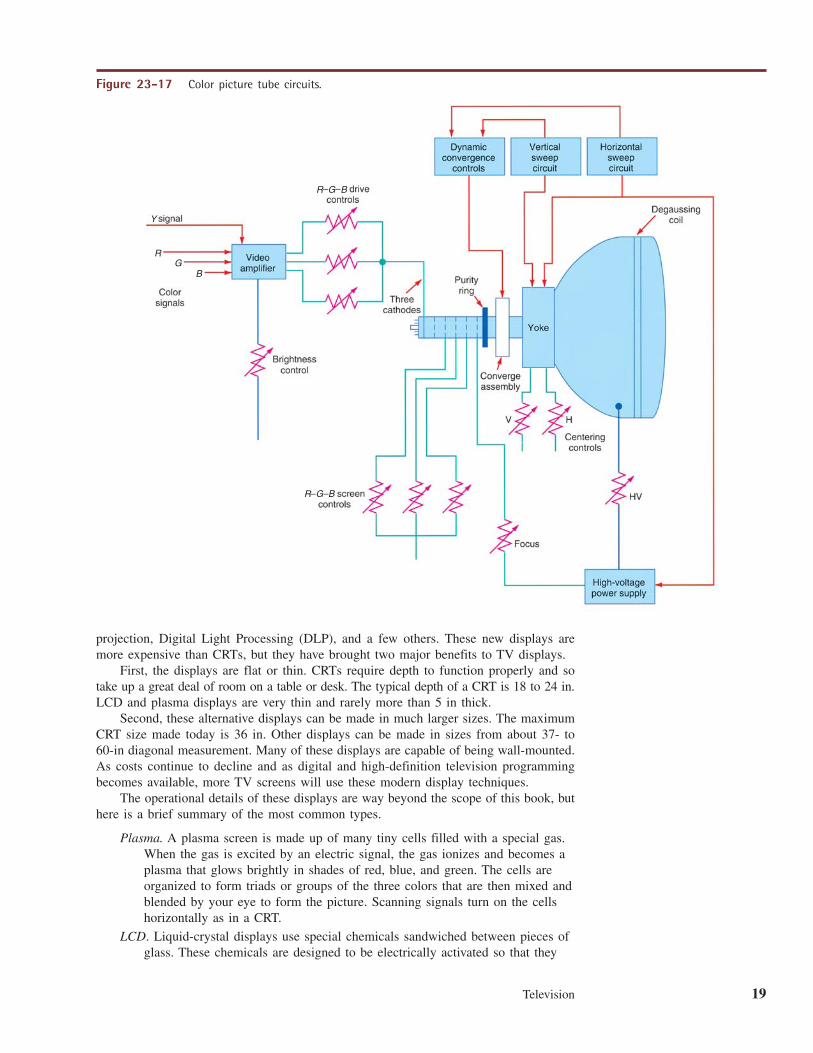
Figure 23-17 shows how all the signals come together at the picture tube to producethe color picture. The R, G, and B signals are mixed with the Y signal to control thecathodes of the CRT. Thus the beams are properly modulated to reproduce the colorpicture. Note the various controls associated with the picture tube. The R-G-B screen,brightness, focus, and centering controls vary the dc voltages that set the levels as desired.The convergence controls and assembly are used to control the positioning of the three
Cathode-ray tube (CRT)
Monochrome CRT
Aquadag
Deflection yoke
Control grid
Color CRT
Triads
Shadow mask
GOOD TO KNOWFor a monochrome CRT or black-
and-white TV, the front of the pic-
ture tube is coated internally with
a phosphor that glows and pro-
duces white light when struck by
an electron beam. A color CRT, on
the other hand, is coated with
red, green, and blue phosphor
dots or stripes which combine to
form the colors visible on the
screen.
18 Chapter 23
electron beams so that they are centered on the holes in the shadow mask and the elec-tron beams strike the color dots dead center. The deflection yoke over the neck of thetube deflects all three electron beams simultaneously.
Other Screen DisplaysWhile most TV sets still use a CRT for a display, during the past 5 years not only havemany other display technologies matured, but also new display methods have beenperfected and brought to market. These include liquid-crystal displays (LCDs), plasma,
Figure 23-16 (a) Basic construction and operation of a black-and-white (monochrome) cathode-ray tube. (b) Details of colorpicture tube.
Television 19
projection, Digital Light Processing (DLP), and a few others. These new displays aremore expensive than CRTs, but they have brought two major benefits to TV displays.
First, the displays are flat or thin. CRTs require depth to function properly and sotake up a great deal of room on a table or desk. The typical depth of a CRT is 18 to 24 in.LCD and plasma displays are very thin and rarely more than 5 in thick.
Second, these alternative displays can be made in much larger sizes. The maximumCRT size made today is 36 in. Other displays can be made in sizes from about 37- to60-in diagonal measurement. Many of these displays are capable of being wall-mounted.As costs continue to decline and as digital and high-definition television programmingbecomes available, more TV screens will use these modern display techniques.
The operational details of these displays are way beyond the scope of this book, buthere is a brief summary of the most common types.
Plasma. A plasma screen is made up of many tiny cells filled with a special gas.When the gas is excited by an electric signal, the gas ionizes and becomes aplasma that glows brightly in shades of red, blue, and green. The cells areorganized to form triads or groups of the three colors that are then mixed andblended by your eye to form the picture. Scanning signals turn on the cellshorizontally as in a CRT.
LCD. Liquid-crystal displays use special chemicals sandwiched between pieces ofglass. These chemicals are designed to be electrically activated so that they
B
B
B
Y
R
R
G
G
R G
Figure 23-17 Color picture tube circuits.
20 Chapter 23
block light or pass light. A bright white light is placed behind the screen.Then the red, blue, and green sections of the screen are enabled to pass thedesired amount of light. The screen is also made in the form of groups ofthree color dots or segments to produce any desired color. Electric signalsscan across the color dots horizontally, as in other TV sets, to reproducethe picture. LCD screens are very common in computer video monitorsbut are now practical for TV sets. As prices decline more TV sets willuse them.
Projection screens. A popular large screen option is an LCD projection TV. Avery bright light is passed through a smaller LCD screen and then through alens, creating a picture from 40 to 60 in diagonally. Another projectionscreen uses Texas Instruments’ Digital Light Processing (DLP) chips. Thesechips are made with microelectromechanical systems (MEMS). They consistof thousands of tiny mirror segments each whose tilt angle is controllable.These mirrors reflect light through color lenses to create a very largeback-projected image.
23-3 Cable TVCable TV, sometimes called CATV, is a system of delivering the TV signal to home receiversby way of a coaxial cable rather than over the air by radio wave propagation. A cable TVcompany collects all the available signals and programs and frequency-multiplexes themon a single coaxial cable that is fed to the homes of subscribers. A special cable decoderbox is used to receive the cable signals, select the desired channel, and feed a signal to theTV set. Today, most TV reception is by way of a cable connection instead of an antenna.
CATV BackgroundMany companies were established to offer TV signals by cable. They put up very tallhigh-gain TV antennas. The resulting signals were amplified and fed to the subscribersby cable. Similar systems were developed for apartments and condominiums. A singlemaster antenna system was installed at a building, and the signals were amplified anddistributed to each apartment or unit by cable.
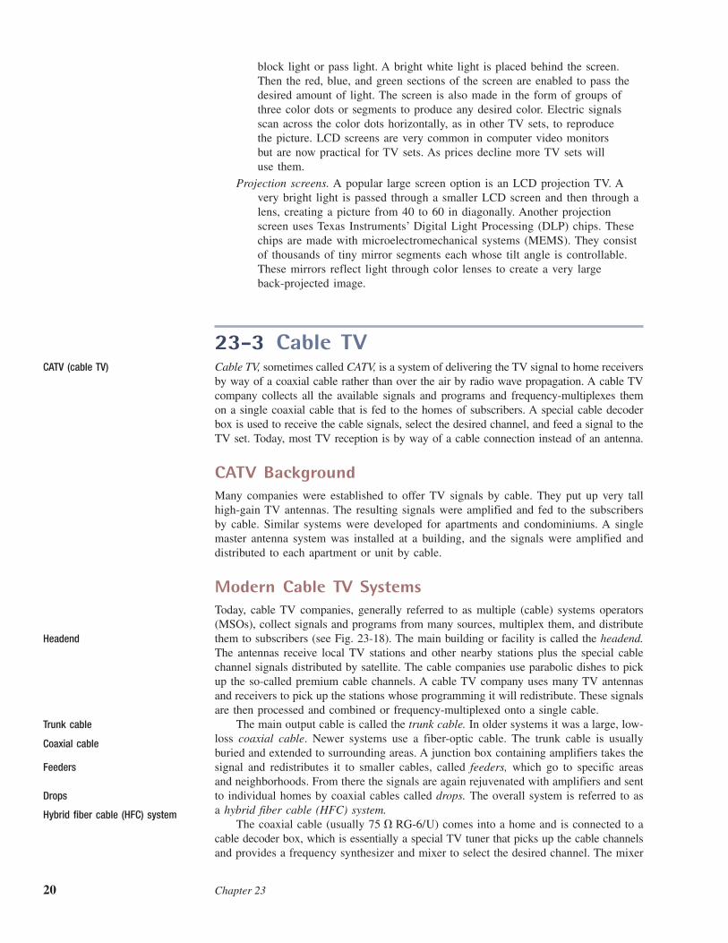
Modern Cable TV SystemsToday, cable TV companies, generally referred to as multiple (cable) systems operators(MSOs), collect signals and programs from many sources, multiplex them, and distributethem to subscribers (see Fig. 23-18). The main building or facility is called the headend.The antennas receive local TV stations and other nearby stations plus the special cablechannel signals distributed by satellite. The cable companies use parabolic dishes to pickup the so-called premium cable channels. A cable TV company uses many TV antennasand receivers to pick up the stations whose programming it will redistribute. These signalsare then processed and combined or frequency-multiplexed onto a single cable.
The main output cable is called the trunk cable. In older systems it was a large, low-loss coaxial cable. Newer systems use a fiber-optic cable. The trunk cable is usuallyburied and extended to surrounding areas. A junction box containing amplifiers takes thesignal and redistributes it to smaller cables, called feeders, which go to specific areasand neighborhoods. From there the signals are again rejuvenated with amplifiers and sentto individual homes by coaxial cables called drops. The overall system is referred to asa hybrid fiber cable (HFC) system.
The coaxial cable (usually ) comes into a home and is connected to acable decoder box, which is essentially a special TV tuner that picks up the cable channelsand provides a frequency synthesizer and mixer to select the desired channel. The mixer
75 � RG-6/U
CATV (cable TV)
Headend
Feeders
Drops
Trunk cable
Coaxial cable
Hybrid fiber cable (HFC) system
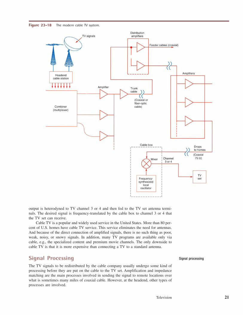
Television 21
output is heterodyned to TV channel 3 or 4 and then fed to the TV set antenna termi-nals. The desired signal is frequency-translated by the cable box to channel 3 or 4 thatthe TV set can receive.
Cable TV is a popular and widely used service in the United States. More than 80 per-cent of U.S. homes have cable TV service. This service eliminates the need for antennas.And because of the direct connection of amplified signals, there is no such thing as poor,weak, noisy, or snowy signals. In addition, many TV programs are available only viacable, e.g., the specialized content and premium movie channels. The only downside tocable TV is that it is more expensive than connecting a TV to a standard antenna.
Signal ProcessingThe TV signals to be redistributed by the cable company usually undergo some kind ofprocessing before they are put on the cable to the TV set. Amplification and impedancematching are the main processes involved in sending the signal to remote locations overwhat is sometimes many miles of coaxial cable. However, at the headend, other types ofprocesses are involved.
(Coaxial or fiber-opticcable)
Frequency-synthesized
localoscillator
Figure 23-18 The modern cable TV system.
Signal processing
22 Chapter 23
Straight-Through Processors. In early cable systems, the TV signals from localstations were picked up with antennas, and the signal was amplified before being mul-tiplexed onto the main cable. This is called straight-through processing. Amplifiers calledstrip amplifiers and tuned to the received channels pass the desired TV signal to the com-biner. Most of these amplifiers include some kind of gain control or attenuators that canreduce the signal level to prevent distortion of strong local signals. This process can stillbe used with local VHF TV stations, but today heterodyne processing is used instead.
Heterodyne Processors. Heterodyne processing translates the incoming TV signalto a different frequency. This is necessary when satellite signals are involved. Microwavecarriers cannot be put on the cable, so they are down-converted to some available 6-MHzTV channel. In addition, heterodyne processing gives the cable companies the flexibil-ity of putting the signals on any channel they want to use.
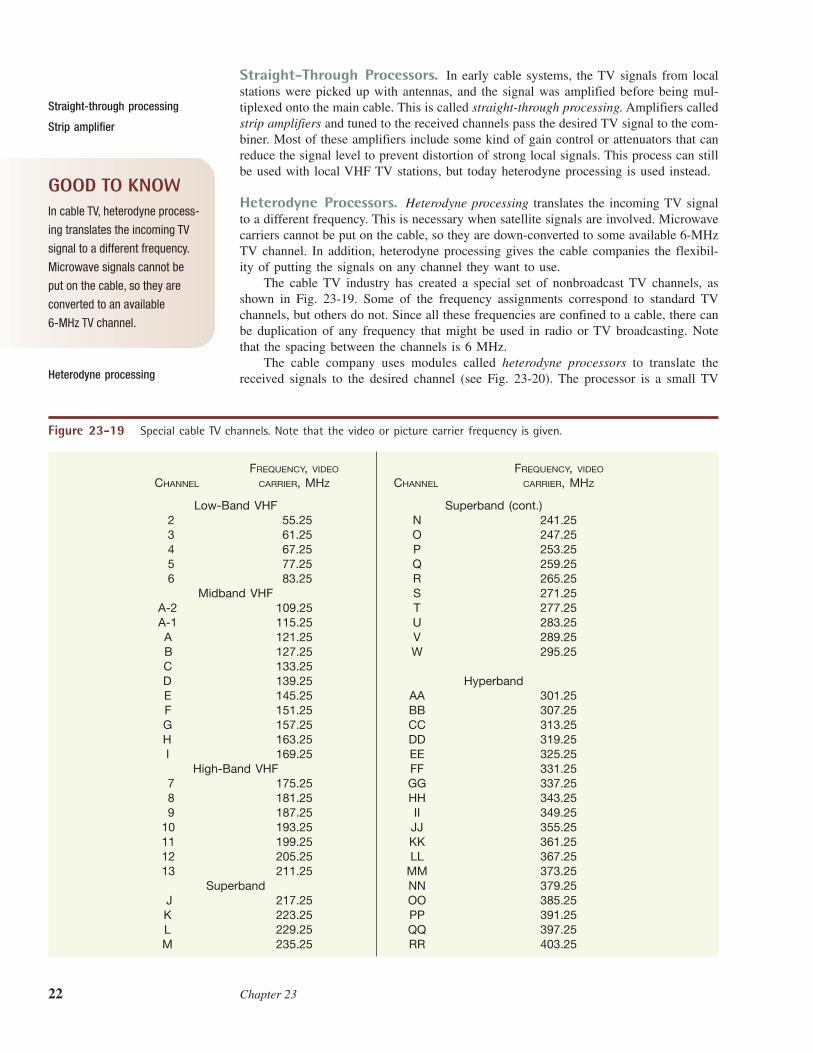
The cable TV industry has created a special set of nonbroadcast TV channels, asshown in Fig. 23-19. Some of the frequency assignments correspond to standard TVchannels, but others do not. Since all these frequencies are confined to a cable, there canbe duplication of any frequency that might be used in radio or TV broadcasting. Notethat the spacing between the channels is 6 MHz.
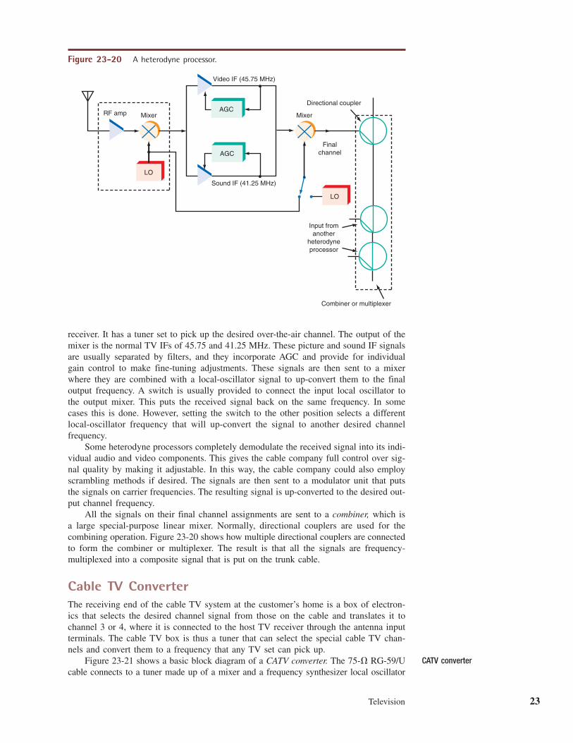
The cable company uses modules called heterodyne processors to translate thereceived signals to the desired channel (see Fig. 23-20). The processor is a small TV
Strip amplifier
Straight-through processing
Heterodyne processing
FREQUENCY, VIDEO FREQUENCY, VIDEO
CHANNEL CARRIER, MHZ CHANNEL CARRIER, MHZ
Low-Band VHF Superband (cont.)2 55.25 N 241.253 61.25 O 247.254 67.25 P 253.255 77.25 Q 259.256 83.25 R 265.25
Midband VHF S 271.25A-2 109.25 T 277.25A-1 115.25 U 283.25A 121.25 V 289.25B 127.25 W 295.25C 133.25D 139.25 HyperbandE 145.25 AA 301.25F 151.25 BB 307.25G 157.25 CC 313.25H 163.25 DD 319.25I 169.25 EE 325.25
High-Band VHF FF 331.257 175.25 GG 337.258 181.25 HH 343.259 187.25 II 349.25
10 193.25 JJ 355.2511 199.25 KK 361.2512 205.25 LL 367.2513 211.25 MM 373.25
Superband NN 379.25J 217.25 OO 385.25K 223.25 PP 391.25L 229.25 QQ 397.25M 235.25 RR 403.25
Figure 23-19 Special cable TV channels. Note that the video or picture carrier frequency is given.
GOOD TO KNOWIn cable TV, heterodyne process-
ing translates the incoming TV
signal to a different frequency.
Microwave signals cannot be
put on the cable, so they are
converted to an available
6-MHz TV channel.
Television 23
receiver. It has a tuner set to pick up the desired over-the-air channel. The output of themixer is the normal TV IFs of 45.75 and 41.25 MHz. These picture and sound IF signalsare usually separated by filters, and they incorporate AGC and provide for individualgain control to make fine-tuning adjustments. These signals are then sent to a mixerwhere they are combined with a local-oscillator signal to up-convert them to the finaloutput frequency. A switch is usually provided to connect the input local oscillator tothe output mixer. This puts the received signal back on the same frequency. In somecases this is done. However, setting the switch to the other position selects a differentlocal-oscillator frequency that will up-convert the signal to another desired channelfrequency.
Some heterodyne processors completely demodulate the received signal into its indi-vidual audio and video components. This gives the cable company full control over sig-nal quality by making it adjustable. In this way, the cable company could also employscrambling methods if desired. The signals are then sent to a modulator unit that putsthe signals on carrier frequencies. The resulting signal is up-converted to the desired out-put channel frequency.
All the signals on their final channel assignments are sent to a combiner, which isa large special-purpose linear mixer. Normally, directional couplers are used for thecombining operation. Figure 23-20 shows how multiple directional couplers are connectedto form the combiner or multiplexer. The result is that all the signals are frequency-multiplexed into a composite signal that is put on the trunk cable.
Cable TV ConverterThe receiving end of the cable TV system at the customer’s home is a box of electron-ics that selects the desired channel signal from those on the cable and translates it tochannel 3 or 4, where it is connected to the host TV receiver through the antenna inputterminals. The cable TV box is thus a tuner that can select the special cable TV chan-nels and convert them to a frequency that any TV set can pick up.
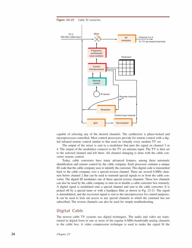
Figure 23-21 shows a basic block diagram of a CATV converter. The RG-59/Ucable connects to a tuner made up of a mixer and a frequency synthesizer local oscillator
75-�
AGC
AGC
LO
LO
Video IF (45.75 MHz)
Mixer MixerRF amp
Sound IF (41.25 MHz)
Finalchannel
Input fromanother
heterodyneprocessor
Combiner or multiplexer
Directional coupler
Figure 23-20 A heterodyne processor.
CATV converter
24 Chapter 23
RFmodulator
Modulator
DemodulatorBPF
Remotecontrol
Frequency-synthesized
local oscillator
Controlmicroprocessor
IR sensor
Channel 3 or 4
To TV set antenna terminal
Keyboard
Reverse channel
Control input channel
75 �RG-59/U cable input
Mixer
Figure 23-21 Cable TV converter.
capable of selecting any of the desired channels. The synthesizer is phase-locked andmicroprocessor-controlled. Most control processors provide for remote control with a dig-ital infrared remote control similar to that used on virtually every modern TV set.
The output of the mixer is sent to a modulator that puts the signal on channel 3 or4. The output of the modulator connects to the TV set antenna input. The TV is then setto the selected channel and left there. All channel changing is done with the cable con-verter remote control.
Today, cable converters have many advanced features, among them automaticidentification and remote control by the cable company. Each processor contains a uniqueID code that the cable company uses to identify the customer. This digital code is transmittedback to the cable company over a special reverse channel. There are several 6-MHz chan-nels below channel 2 that can be used to transmit special signals to or from the cable con-verter. The digital ID modulates one of these special reverse channels. These low channelscan also be used by the cable company to turn on or disable a cable converter box remotely.A digital signal is modulated onto a special channel and sent to the cable converter. It ispicked off by a special tuner or with a bandpass filter as shown in Fig. 23-21. The signalis demodulated, and the recovered signal is sent to the microprocessor for control purposes.It can be used to lock out access to any special channels to which the customer has notsubscribed. The reverse channels can also be used for simple troubleshooting.
Digital CableThe newest cable TV systems use digital techniques. The audio and video are trans-mitted in digital form in one or more of the regular 6-MHz-bandwidth analog channelsto the cable box. A video compression technique is used to make the signal fit the
Television 25
available channel bandwidth. Digital modulation methods are used, mainly multilevelQAM (16-QAM, 32-QAM, or 64-QAM). The cable box at the receiving end containsdigital demodulator and decompression circuits and D/A converters to put the signalsinto analog form for presentation on the still-analog TV set. The primary benefits ofdigital cable are that more channels can be carried and the picture quality is somewhatbetter. However, cable TV systems with digital cable also continue to support the olderanalog TV system since it is less expensive.
Cable TV systems use a set of standards established by Cable Labs, a nonprofit orga-nization devoted to research into cable TV methods as well as programs of testing andcertification that ensure that any cable TV set or converter box is compatible with anyTV set or cable TV system. Cable Labs has developed a system that also permits cableTV channels to carry high-speed Internet service as well as Voice over Internet Protocol(VoIP) phone service. This standard is called Data over Cable Service Interface Specifi-cation (DOCSIS). The latest version 3.0 defines wider 6.4-MHz channels, 64-QAM mod-ulation, and a data rate up to 30 Mbps. With such flexibility, DOCSIS permits cable TVcompanies to offer virtually any digital service to the consumer. Digital TV, Internet, andphone service combined is called the triple play.
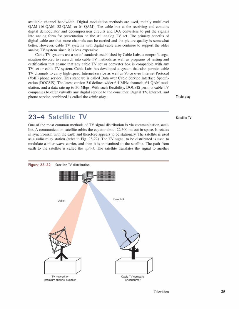
23-4 Satellite TVOne of the most common methods of TV signal distribution is via communication satel-lite. A communication satellite orbits the equator about 22,300 mi out in space. It rotatesin synchronism with the earth and therefore appears to be stationary. The satellite is usedas a radio relay station (refer to Fig. 23-22). The TV signal to be distributed is used tomodulate a microwave carrier, and then it is transmitted to the satellite. The path fromearth to the satellite is called the uplink. The satellite translates the signal to another
Satellite TV
Triple play
TV network orpremium channel supplier
Cable TV companyor consumer
Uplink Downlink
Figure 23-22 Satellite TV distribution.
26 Chapter 23
frequency and then retransmits it back to earth. This is called the downlink. A receivesite on earth picks up the signal. The receive site may be a cable TV company or anindividual consumer. Satellites are widely used by the TV networks, the premium chan-nel companies, and the cable TV industry for distributing signals nationally.
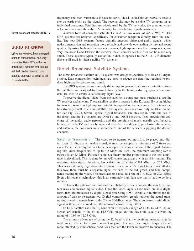
A newer form of consumer satellite TV is direct broadcast satellite (DBS) TV. TheDBS systems are designed specifically for consumer reception directly from the satel-lite. The new DBS systems feature digitally encoded video and audio signals, whichmake transmission and reception more reliable and provide outstanding picture and soundquality. By using higher-frequency microwaves, higher-power satellite transponders, andvery low-noise GaAs FETs in the receiver, the customer’s satellite dish can be made verysmall. These systems typically use an 18-in dish as opposed to the 5- to 12-ft-diameterdishes still used in older satellite TV systems.
Direct Broadcast Satellite SystemsThe direct broadcast satellite (DBS) system was designed specifically to be an all-digitalsystem. Data compression techniques are used to reduce the data rate required to pro-duce high-quality picture and sound.
The DBS system features entirely digital uplink ground stations and satellites. Sincethe satellites are designed to transmit directly to the home, extra high-power transpon-ders are used to ensure a satisfactory signal level.
To receive the digital video from the satellite, a consumer must purchase a satelliteTV receiver and antenna. These satellite receivers operate in the band. By using higherfrequencies as well as higher-power satellite transponders, the necessary dish antenna canbe extremely small. The new satellite DBS system antennas have only an 18-in diame-ter. See Fig. 23-23. Several special digital broadcast satellites are in orbit, and two ofthe direct satellite TV sources are DirecTV and DISH Network. They provide full cov-erage of the major cable networks, and the premium channels usually distributed tohomes by cable TV and can be received directly. In addition to purchasing the receiverand antenna, the consumer must subscribe to one of the services supplying the desiredchannels.
Satellite Transmission. The video to be transmitted must first be placed into digi-tal form. To digitize an analog signal, it must be sampled a minimum of 2 times percycle for sufficient digital data to be developed for reconstruction of the signal. Assum-ing that video frequencies of up to 4.2 Mbps are used, the minimum sampling rate istwice this, or 8.4 Mbps. For each sample, a binary number proportional to the light ampli-tude is developed. This is done by an A/D converter, usually with an 8-bit output. Theresulting video signal, therefore, has a data rate of 8 bits � 8.4 Mbps, or 67.2 Mbps.This is an extremely high data rate. However, for a color TV signal to be transmitted inthis way, there must be a separate signal for each of the red, green, and blue compo-nents making up the video. This translates to a total data rate of or 202, Mbps.Even with today’s technology, this is an extremely high data rate that is hard to achievereliably.
To lower the data rate and improve the reliability of transmission, the new DBS sys-tem uses compressed digital video. Once the video signals have been put into digitalform, they are processed by digital signal processing (DSP) circuits to minimize the fullamount of data to be transmitted. Digital compression greatly reduces the actual trans-mitting speed to somewhere in the 20- to 30-Mbps range. The compressed serial digitalsignal is then used to modulate the uplinked carrier using BPSK.
The DBS satellite uses the band with a frequency range of 11 to 14 GHz. Uplinksignals are usually in the 14- to 14.5-GHz range, and the downlink usually covers therange of 10.95 to 12.75 GHz.
The primary advantage of using the band is that the receiving antennas may bemade much smaller for a given amount of gain. However, these higher frequencies aremore affected by atmospheric conditions than are the lower microwave frequencies. The
Ku
Ku
3 � 67.2,
Ku
Direct broadcast satellite (DBS) TV
GOOD TO KNOWUsing microwaves, high-powered
satellite transponders, and very
low-noise GaAs FETs in the re-
ceiver, DBS systems create a sig-
nal that can be received by a
satellite dish with as small as an
18-in diameter.
Television 27
biggest problem is the increased attenuation of the downlink signal caused by rain. Anytype of weather involving rain or water vapor, such as fog, can seriously reduce thereceived signal. This is so because the wavelength of band signals is near that ofwater vapor. Therefore, the water vapor absorbs the signal. Although the power of thesatellite transponder and the gain of the receiving antenna are typically sufficient to pro-vide solid reception, there can be fadeout under heavy downpour conditions.
Finally, the digital signal is transmitted from the satellite to the receiver by usingcircular polarization. The DBS satellites have right-hand and left-hand circularly polar-ized (RHCP and LHCP) helical antennas. By transmitting both polarities of signal, fre-quency reuse can be incorporated to double the channel capacity.
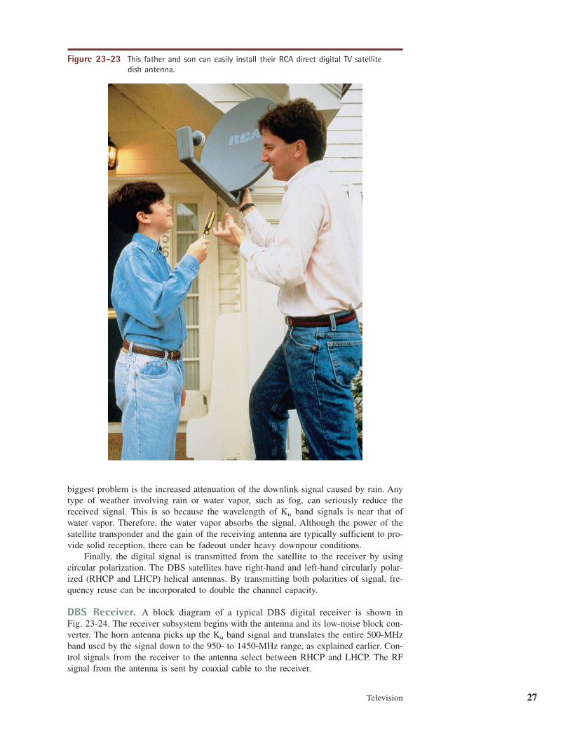
DBS Receiver. A block diagram of a typical DBS digital receiver is shown inFig. 23-24. The receiver subsystem begins with the antenna and its low-noise block con-verter. The horn antenna picks up the band signal and translates the entire 500-MHzband used by the signal down to the 950- to 1450-MHz range, as explained earlier. Con-trol signals from the receiver to the antenna select between RHCP and LHCP. The RFsignal from the antenna is sent by coaxial cable to the receiver.
Ku
Ku
Figure 23-23 This father and son can easily install their RCA direct digital TV satellitedish antenna.
28 Chapter 23
A typical DBS downlink signal occurs in the 12.2- to 12.7-GHz portion of the band. Each transponder has a bandwidth of approximately 24 MHz. The digital signalusually occurs at a rate of approximately 27 Mbps.
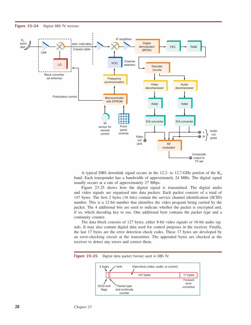
Figure 23-25 shows how the digital signal is transmitted. The digital audioand video signals are organized into data packets. Each packet consists of a total of147 bytes. The first 2 bytes (16 bits) contain the service channel identification (SCID)number. This is a 12-bit number that identifies the video program being carried by thepacket. The 4 additional bits are used to indicate whether the packet is encrypted and,if so, which decoding key to use. One additional byte contains the packet type and acontinuity counter.
The data block consists of 127 bytes, either 8-bit video signals or 16-bit audio sig-nals. It may also contain digital data used for control purposes in the receiver. Finally,the last 17 bytes are the error detection check codes. These 17 bytes are developed byan error-checking circuit at the transmitter. The appended bytes are checked at thereceiver to detect any errors and correct them.
Ku
D/A converter D/A converter
RAM RAM
LO
Frequencysynchronization
Videodecompresser
Audiodecompresser
RFmodulator
VCO
FEC RAM
Decodercircuits
Kubanddish
LNA
950–1450 MHz
Coaxial cable
Digitaldemodulator
(BPSK)
Channelselection
IF amplifiers
IRsensor for
remotecontrol
Frontpanel
controls
Block converter(at antenna)
Polarization control
L
R
Audioout
jacksVideooutjack
Compositeoutput toTV set
Microcontrollerwith EPROM
Figure 23-24 Digital DBS TV receiver.
2 bytes 1 byte Data block (video, audio, or control)
127 bytes 17 bytes
SCID andflags
Packet typeand continuity
counter
Forwarderror
correction
Figure 23-25 Digital data packet format used in DBS TV.
Television 29
The received signal is passed through another mixer with a variable-frequency localoscillator to provide channel selection. The digital signal at the second IF is then demodu-lated to recover the originally transmitted digital signal, which is passed through a forwarderror correction (FEC) circuit. This circuit is designed to detect bit errors in the transmis-sion and to correct them on the fly. Any bits lost or obscured by noise during the trans-mission process are usually caught and corrected to ensure a near-perfect digital signal.
The resulting error-corrected signals are then sent to the audio and video decom-pression circuits. Then they are stored in random access memory (RAM), after whichthe signal is decoded to separate it into both the video and the audio portions. The DBSTV system uses digital compression-decompression standards referred to as MPEG2(MPEG means Moving Picture Experts Group, which is a standards organization thatestablishes technical standards for movies and video). MPEG2 is a compression methodfor video that achieves a compression of about 50 to 1 in data rate. Finally, the signalsare sent to D/A converters that modulate the RF modulator which sends the signals tothe TV set antenna terminals.
Although the new DBS digital systems will not replace cable TV, they provide theconsumer with the capability of receiving a wide range of TV channels. The use of dig-ital techniques provides an unusually high-quality signal.
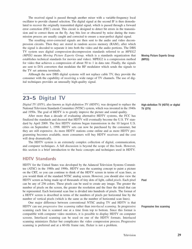
23-5 Digital TVDigital TV (DTV), also known as high-definition TV (HDTV), was designed to replace theNational Television Standards Committee (NTSC) system, which was invented in the 1940sand 1950s. The goal of HDTV is to greatly improve the picture and sound quality.
After more than a decade of evaluating alternative HDTV systems, the FCC hasfinalized the standards and decreed that HDTV will eventually become the U.S. TV stan-dard by April 2009. The first HDTV stations began transmission in the 10 largest U.S.cities on September 1, 1998. HDTV sets can now be purchased by the consumer, butthey are still expensive. As more HDTV stations come online and as more HDTV pro-gramming becomes available, more consumers will buy HDTV receivers and the costwill drop dramatically.
The HDTV system is an extremely complex collection of digital, communication,and computer techniques. A full discussion is beyond the scope of this book. However,this section is a brief introduction to the basic concepts and techniques used in HDTV.
HDTV StandardsHDTV for the United States was developed by the Adanced Television Systems Commit-tee (ATSC) in the 1980s and 1990s. HDTV uses the scanning concept to paint a pictureon the CRT, so you can continue to think of the HDTV screen in terms of scan lines, asyou would think of the standard NTSC analog screen. However, you should also view theHDTV screen as being made up of thousands of tiny dots of light, called pixels. Each pixelcan be any of 256 colors. These pixels can be used to create any image. The greater thenumber of pixels on the screen, the greater the resolution and the finer the detail that canbe represented. Each horizontal scan line is divided into hundreds of pixels. The format ofa HDTV screen is described in terms of the numbers of pixels per horizontal line by thenumber of vertical pixels (which is the same as the number of horizontal scan lines).
One major difference between conventional NTSC analog TV and HDTV is thatHDTV can use progressive line scanning rather than interlaced scanning. In progressivescanning each line is scanned one at a time from top to bottom. Since this format iscompatible with computer video monitors, it is possible to display HDTV on computerscreens. Interlaced scanning can be used on one of the HDTV formats. Interlacedscanning minimizes flicker but complicates the video compression process. Progressivescanning is preferred and at a 60-Hz frame rate, flicker is not a problem.
Moving Picture Experts Group(MPEG)
High-definition TV (HDTV) or digitalTV (DTV)
Progressive line scanning
Pixel
30 Chapter 23
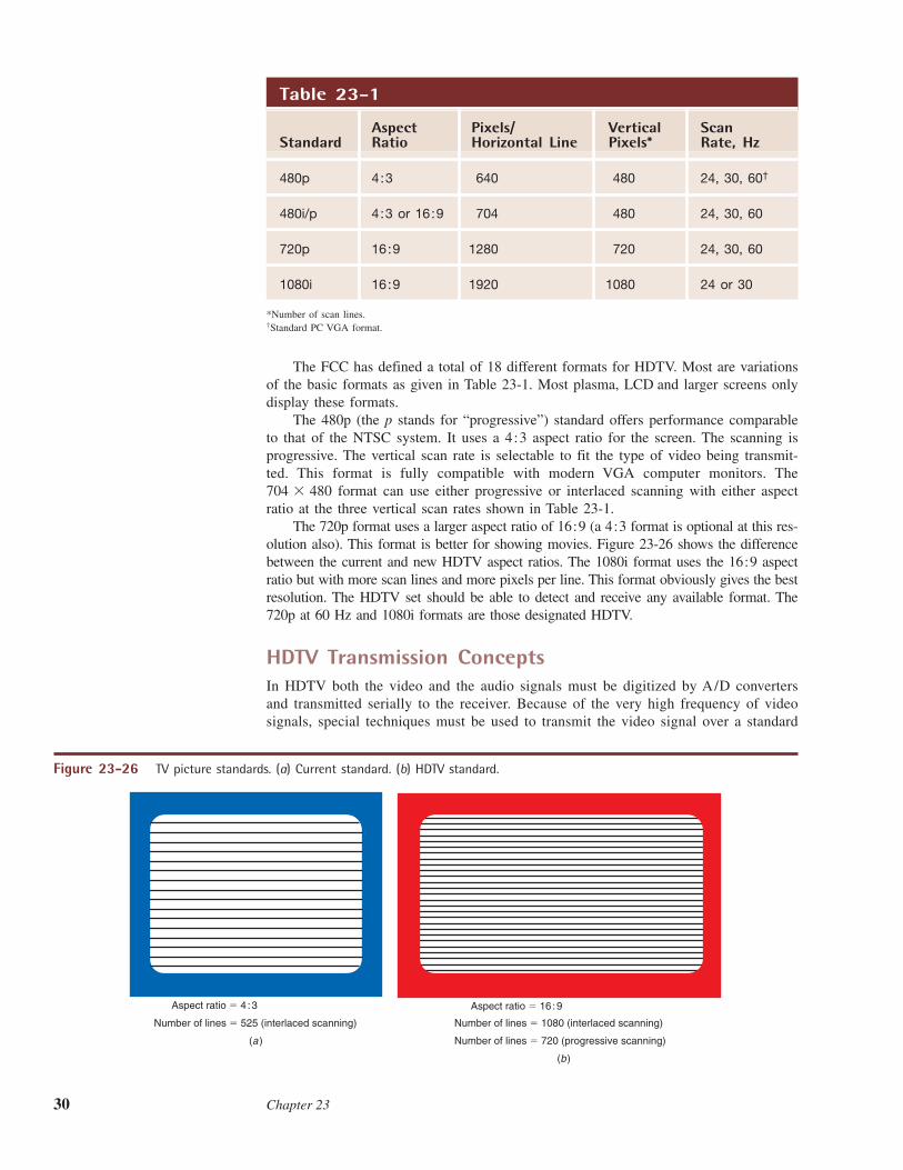
The FCC has defined a total of 18 different formats for HDTV. Most are variationsof the basic formats as given in Table 23-1. Most plasma, LCD and larger screens onlydisplay these formats.
The 480p (the p stands for “progressive”) standard offers performance comparableto that of the NTSC system. It uses a 4:3 aspect ratio for the screen. The scanning isprogressive. The vertical scan rate is selectable to fit the type of video being transmit-ted. This format is fully compatible with modern VGA computer monitors. The
format can use either progressive or interlaced scanning with either aspectratio at the three vertical scan rates shown in Table 23-1.
The 720p format uses a larger aspect ratio of 16:9 (a 4:3 format is optional at this res-olution also). This format is better for showing movies. Figure 23-26 shows the differencebetween the current and new HDTV aspect ratios. The 1080i format uses the 16:9 aspectratio but with more scan lines and more pixels per line. This format obviously gives the bestresolution. The HDTV set should be able to detect and receive any available format. The720p at 60 Hz and 1080i formats are those designated HDTV.
HDTV Transmission ConceptsIn HDTV both the video and the audio signals must be digitized by A/D convertersand transmitted serially to the receiver. Because of the very high frequency of videosignals, special techniques must be used to transmit the video signal over a standard
704 � 480
Table 23-1
Aspect Pixels/ Vertical ScanStandard Ratio Horizontal Line Pixels* Rate, Hz
480p 4:3 640 480 24, 30, 60†
480i/p 4:3 or 16:9 704 480 24, 30, 60
720p 16:9 1280 720 24, 30, 60
1080i 16:9 1920 1080 24 or 30
*Number of scan lines.†Standard PC VGA format.
Aspect ratio � 4 : 3
Number of lines � 525 (interlaced scanning)
Aspect ratio � 16 : 9
Number of lines � 1080 (interlaced scanning)
Number of lines � 720 (progressive scanning)(a )
(b)
Figure 23-26 TV picture standards. (a) Current standard. (b) HDTV standard.
Television 31
6-MHz-bandwidth TV channel. And because both video and audio must be transmittedover the same channel, multiplexing techniques must be used. The FCC’s requirement isthat all this information be transmitted reliably over the standard 6-MHz TV channelsnow defined for NTSC TV.
Assume that the video to be transmitted contains frequencies up to 4.2 MHz. Forthis signal to be digitized, it must be sampled at least 2 times per cycle or at a minimumsampling rate of 8.4 MHz. If each sample is translated to an 8-bit word (byte) and thebytes are transmitted serially, the data stream has a rate of , or 67.2 MHz.Multiply this by 3 to get 67.2 � 3 = 201.6 MHz. Add to this the audio channels, andthe total required bandwidth is almost 300 MHz. To permit this quantity of data to betransmitted over the 6-MHz channel, special encoding and modulation techniques areused.
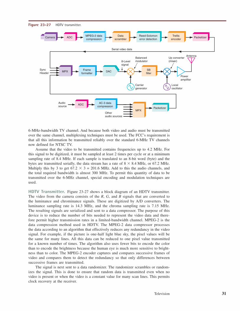
HDTV Transmitter. Figure 23-27 shows a block diagram of an HDTV transmitter.The video from the camera consists of the R, G, and B signals that are converted tothe luminance and chrominance signals. These are digitized by A/D converters. Theluminance sampling rate is 14.3 MHz, and the chroma sampling rate is 7.15 MHz.The resulting signals are serialized and sent to a data compressor. The purpose of thisdevice is to reduce the number of bits needed to represent the video data and there-fore permit higher transmission rates in a limited-bandwidth channel. MPEG-2 is thedata compression method used in HDTV. The MPEG-2 data compressor processesthe data according to an algorithm that effectively reduces any redundancy in the videosignal. For example, if the picture is one-half light blue sky, the pixel values will bethe same for many lines. All this data can be reduced to one pixel value transmittedfor a known number of times. The algorithm also uses fewer bits to encode the colorthan to encode the brightness because the human eye is much more sensitive to bright-ness than to color. The MPEG-2 encoder captures and compares successive frames ofvideo and compares them to detect the redundancy so that only differences betweensuccessive frames are transmitted.
The signal is next sent to a data randomizer. The randomizer scrambles or random-izes the signal. This is done to ensure that random data is transmitted even when novideo is present or when the video is a constant value for many scan lines. This permitsclock recovery at the receiver.
8 � 8.4 MHz
Camera ADC MPEG-2 datacompression
SyncHeader
Audiosource
Otheraudio sources
8-Levelsignal
Balancedmodulator
Carriergenerator
Localoscillator
Poweramplifier
Antenna
Serial video data
Packetizer
Packetizer
MPX Frameformatter
SBfilter
Datascrambler
ADC AC-3 datacompression
Trellisencoder
Reed-Solomonerror detection
MPX
DAC
Up converter(mixer)
Figure 23-27 HDTV transmitter.
32 Chapter 23
Next the random serial signal is passed through a Reed-Solomon (RS) errordetection and correction circuit. This circuit adds extra bits to the data stream so thattransmission errors can be detected at the receiver and corrected. This ensures high reli-ability in signal transmission even under severe noise conditions. In HDTV, the RS encoderadds 20 parity bytes per block of data that can provide correction for up to 10 byte errorsper block.
The signal is next fed to a trellis encoder. This circuit further modifies the data topermit error correction at the receiver. Trellis encoding is widely used in modems. Trel-lis coding is not used in the cable TV version of HDTV.
The audio portion of the HDTV signal is also digital. It provides for compact disk(CD) quality audio. The audio system can accommodate up to six audio channels, per-mitting monophonic sound, stereo, and multichannel surround sound. The channelarrangement is flexible to permit different systems. For example, one channel could beused for a second language transmission or closed captioning.
Each audio channel is sampled at a 48-kbps rate, ensuring that audio signals up toabout 24 kHz are accurately captured and transmitted. Each audio sample is convertedto an 18-bit digital word. The audio information is time-multiplexed and transmitted asa serial bit stream at a frequency of Adata compression technique designated AC-3 is used to speed up audio transmission.
5.185 Mbps.48 kbps � 6 channels � 18 bits �
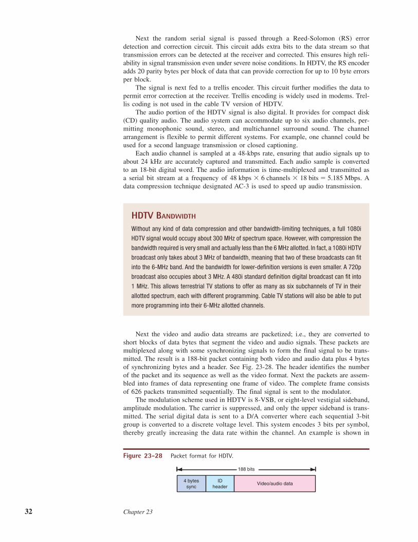
4 bytessync
IDheader
Video/audio data
188 bits
Figure 23-28 Packet format for HDTV.
HDTV BANDWIDTH
Without any kind of data compression and other bandwidth-limiting techniques, a full 1080i
HDTV signal would occupy about 300 MHz of spectrum space. However, with compression the
bandwidth required is very small and actually less than the 6 MHz allotted. In fact, a 1080i HDTV
broadcast only takes about 3 MHz of bandwidth, meaning that two of these broadcasts can fit
into the 6-MHz band. And the bandwidth for lower-definition versions is even smaller. A 720p
broadcast also occupies about 3 MHz. A 480i standard definition digital broadcast can fit into
1 MHz. This allows terrestrial TV stations to offer as many as six subchannels of TV in their
allotted spectrum, each with different programming. Cable TV stations will also be able to put
more programming into their 6-MHz allotted channels.
Next the video and audio data streams are packetized; i.e., they are converted toshort blocks of data bytes that segment the video and audio signals. These packets aremultiplexed along with some synchronizing signals to form the final signal to be trans-mitted. The result is a 188-bit packet containing both video and audio data plus 4 bytesof synchronizing bytes and a header. See Fig. 23-28. The header identifies the numberof the packet and its sequence as well as the video format. Next the packets are assem-bled into frames of data representing one frame of video. The complete frame consistsof 626 packets transmitted sequentially. The final signal is sent to the modulator.
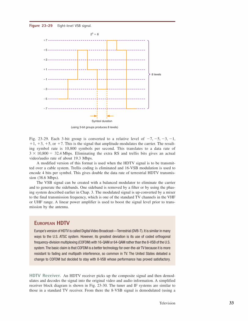
The modulation scheme used in HDTV is 8-VSB, or eight-level vestigial sideband,amplitude modulation. The carrier is suppressed, and only the upper sideband is trans-mitted. The serial digital data is sent to a D/A converter where each sequential 3-bitgroup is converted to a discrete voltage level. This system encodes 3 bits per symbol,thereby greatly increasing the data rate within the channel. An example is shown in
Television 33
Fig. 23-29. Each 3-bit group is converted to a relative level of or This is the signal that amplitude-modulates the carrier. The result-
ing symbol rate is 10,800 symbols per second. This translates to a data rate of. Eliminating the extra RS and trellis bits gives an actual
video/audio rate of about 19.3 Mbps.A modified version of this format is used when the HDTV signal is to be transmit-
ted over a cable system. Trellis coding is eliminated and 16-VSB modulation is used toencode 4 bits per symbol. This gives double the data rate of terrestrial HDTV transmis-sion (38.6 Mbps).
The VSB signal can be created with a balanced modulator to eliminate the carrierand to generate the sidebands. One sideband is removed by a filter or by using the phas-ing system described earlier in Chap. 3. The modulated signal is up-converted by a mixerto the final transmission frequency, which is one of the standard TV channels in the VHFor UHF range. A linear power amplifier is used to boost the signal level prior to trans-mission by the antenna.
32.4 Mbps3 � 10,800 �
�7.�1, �3, �5,�7, �5, �3, �1,
Symbol duration
23 � 8
(using 3-bit groups produces 8 levels)
�7
�5
�3
�1
�1
�3
�5
�7
8 levels
Figure 23-29 Eight-level VSB signal.
EUROPEAN HDTVEurope’s version of HDTV is called Digital Video Broadcast—Terrestrial (DVB-T). It is similar in many
ways to the U.S. ATSC system. However, its greatest deviation is its use of coded orthogonal
frequency-division multiplexing (COFDM) with 16-QAM or 64-QAM rather than the 8-VSB of the U.S.
system.The basic claim is that COFDM is a better technology for over-the-air TV because it is more
resistant to fading and multipath interference, so common in TV. The United States debated a
change to COFDM but decided to stay with 8-VSB whose performance has proved satisfactory.
HDTV Receiver. An HDTV receiver picks up the composite signal and then demod-ulates and decodes the signal into the original video and audio information. A simplifiedreceiver block diagram is shown in Fig. 23-30. The tuner and IF systems are similar tothose in a standard TV receiver. From there the 8-VSB signal is demodulated (using a
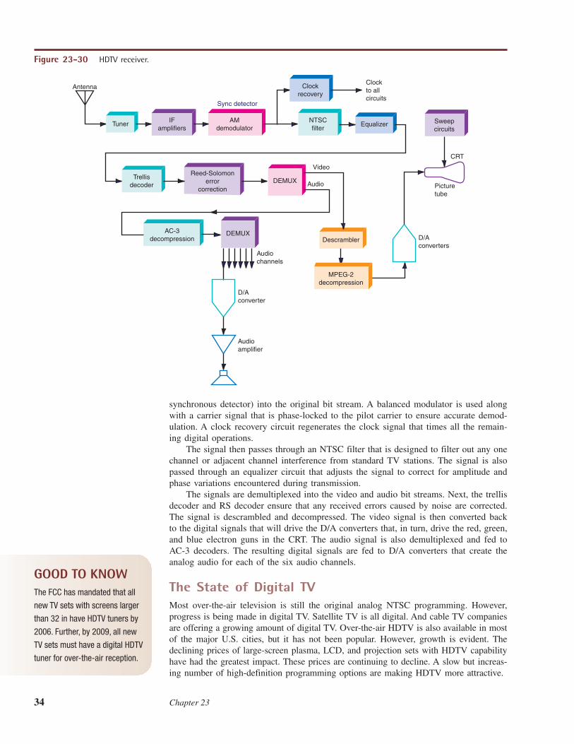
34 Chapter 23
synchronous detector) into the original bit stream. A balanced modulator is used alongwith a carrier signal that is phase-locked to the pilot carrier to ensure accurate demod-ulation. A clock recovery circuit regenerates the clock signal that times all the remain-ing digital operations.
The signal then passes through an NTSC filter that is designed to filter out any onechannel or adjacent channel interference from standard TV stations. The signal is alsopassed through an equalizer circuit that adjusts the signal to correct for amplitude andphase variations encountered during transmission.
The signals are demultiplexed into the video and audio bit streams. Next, the trellisdecoder and RS decoder ensure that any received errors caused by noise are corrected.The signal is descrambled and decompressed. The video signal is then converted backto the digital signals that will drive the D/A converters that, in turn, drive the red, green,and blue electron guns in the CRT. The audio signal is also demultiplexed and fed toAC-3 decoders. The resulting digital signals are fed to D/A converters that create theanalog audio for each of the six audio channels.
The State of Digital TVMost over-the-air television is still the original analog NTSC programming. However,progress is being made in digital TV. Satellite TV is all digital. And cable TV companiesare offering a growing amount of digital TV. Over-the-air HDTV is also available in mostof the major U.S. cities, but it has not been popular. However, growth is evident. Thedeclining prices of large-screen plasma, LCD, and projection sets with HDTV capabilityhave had the greatest impact. These prices are continuing to decline. A slow but increas-ing number of high-definition programming options are making HDTV more attractive.
Video
Audio
Sync detector
Antenna
D/Aconverters
Picturetube
CRT
Clockto allcircuits
DEMUX
D/Aconverter
Audioamplifier
Audiochannels
IFamplifiers
Tuner
Clockrecovery
AMdemodulator
Sweepcircuits
EqualizerNTSCfilter
Reed-Solomonerror
correction
DEMUX
Trellisdecoder
DEMUX
AC-3decompression Descrambler
MPEG-2decompression
Figure 23-30 HDTV receiver.
GOOD TO KNOWThe FCC has mandated that all
new TV sets with screens larger
than 32 in have HDTV tuners by
2006. Further, by 2009, all new
TV sets must have a digital HDTV
tuner for over-the-air reception.
Television 35
But despite the slow growth, the U.S. government is anxious to initiate a completeswitch to digital in the coming years. The previous declared deadline was the end of 2006,but Congress has moved that date out to February 17, 2009. At the heart of this initiativeis the government’s desire to reclaim a large portion of the UHF TV spectrum (roughly500 to 800 MHz) to auction off to cell phone companies for expanded growth. Spectrumis also needed for new land mobile communications services and equipment that areexpected to help resolve the incompatibility of radio services among the various city police,fire, and public services. The goal is to create fully interoperable radios for all government,military, and other agencies to allow them to communicate reliably during disasters.
When 2009 arrives, all current NTSC analog transmission will cease and everyonewill have to switch to HDTV. A new TV set is the best option, but for those who can-not afford one, the government will subsidize special converter boxes that will receivethe HDTV signals and convert them to standard analog output for older TV sets.
In the meantime, another form of digital TV is emerging. Known as IPTV or InternetProtocol TV, this form of TV will be transmitted using standard TCP/IP over high-speedInternet connections such as those furnished by cable TV companies and DSL carriers.Standard phone companies (AT&T, Verizon, etc.) will compete with cable TV compa-nies to distribute TV to consumers. The adoption of more advanced video compressiontechniques such as the ITU-T’s H.264 standard, also known as MPEG-4 compression, isexpected to further improve picture quality while minimizing bandwidth.
A special form of TV now being developed is that created for use on cell phones andother small-screen devices. Known as DVB-H, it is a form of digital TV derived from theEuropean Digital Video Broadcast (DVB) standard. The video is not high-definition sincethe small screens have such a small pixel count. Services to deliver small-screen TV arebeing developed in the 1670- to 1675-MHz band. An alternate service called MediaFLOuses the 716- to 722-MHz band, formerly the channel 55 UHF spectrum.
In general, the United States is well behind the rest of the world in converting todigital television. The technology is here now and has been for a number of years. Theconversion is inevitable but happening on a timetable controlled by government, politics,economics, and public acceptance.
Summary
CHAPTER REVIEW
Television is radio communication with both pictures andsound. In addition to standard audio transmission, TV systemsuse a camera to convert a visual scene to a voltage known as thevideo signal. This signal represents the picture information andmodulates a transmitter. The picture and the sound signals aretransmitted to the receiver. The receiver demodulates the sig-nals and presents the information to the user. The TV receiveris a special superheterodyne that recovers the sound and pictureinformation. The picture is displayed on a picture tube.
As common as a TV set is, we usually take for grantedthe extremely complex process involved in receiving a TVsignal and recovering it to present the picture and sound out-puts in a high-quality manner. During the several decadessince its invention, the TV set has evolved from a largevacuum tube unit into a smaller, more reliable solid-stateunit made mostly with ICs.
Although TV signals are still transmitted by radio,today most people get their TV signals via a hybrid fiber-optic coaxial cable system. A converter box at the TV setconverts the cable signals to a format compatible with theTV receiver.
One of the most common means of TV signal distribu-tion is via communication satellite. A communication satel-lite orbits the equator about 22,300 mi out in space. In thisposition it rotates in synchronism with the earth and there-fore appears to be stationary. The satellite is used as a radiorelay station. Satellites are widely used by the TV networks,the premium channel companies, and the cable TV industryfor distributing their signals nationally. A newer form of con-sumer satellite is direct broadcast satellite (DBS) TV. TheDBS systems are designed for consumer reception directlyfrom the satellite.
36 Chapter 23
The newest form of TV uses digital methods. Known asdigital TV (DTV) or high-definition TV (HDTV), these newsystems offer improved picture resolution and quality as well
as stereo sound. HDTV will be delivered over the air and bycable TV companies.
1. What is the bandwidth of a standard TV signal?2. State the kind of modulation used on the video carrier
and the sound carrier in a TV signal.3. What is the frequency spacing between the sound and
picture carriers?4. What do you call the brightness signal produced by a
video monochrome video camera?5. Name two widely used electronic imaging devices in TV
cameras that convert light variations to a video signal.6. What is the name of the process that breaks up a pic-
ture or scene into serially transmitted signals?7. What are the three basic colors that can be used to pro-
duce any other color light?8. What is the maximum number of scan lines used in an
NTSC TV picture or frame of video?9. How many scan lines make up one field of a TV picture?
10. What are the field and frame rates in NTSC color TV?11. What is the rate of scanning one horizontal line in a
color TV set?12. What is the name of the circuit that lets the picture
and sound transmitters use the same antenna?13. The color camera signals are combined in a resistive
matrix to produce the two composite color signals.What are they called?
14. How are the two color signals multiplexed and modu-lated onto the main video carrier?
15. What is the frequency of the subcarrier that the colorsignals modulate?
16. What characteristic of the composite color signaltells the receiver what the transmitted color is?
17. What type of modulation is used in the generation ofthe chrominance signals?
18. What portion of a modern TV set uses digitally codedinfrared signals to control channel selection and vol-ume level?
19. What is the name of the special filter that providesmost of the selectivity for the TV receiver?
20. The picture and sound IFs are heterodyned together toform the sound IF. What is its frequency?
21. Name two common sound demodulators in TV receivers.22. What is meant by a quadrature 3.58-MHz subcarrier
as used in demodulation?23. What circuit strips the horizontal sync pulses from the
video detector output?24. The horizontal sync pulses synchronize an internal sweep
oscillator to what frequency in a color TV receiver?25. What is the shape of the horizontal and vertical sweep
signals which are currents applied to the horizontaland vertical deflection coils?
26. What is the name of the assembly around the neck ofthe picture tube to which the sweep signals are ap-plied?
27. What element in the picture tube generates the elec-trons? What element in the picture tube focuses theelectrons into a narrow beam?
28. By what process is the electron beam deflected andswept across the face of the picture tube?
29. How many electron guns are used in a color CRT toexcite the color dot triads on the face of the tube?
30. What is the name of the circuits that ensure that theelectron beams strike the correct color dots?
31. What stage in the TV receiver is used as a switchingpower supply to develop the high voltage required tooperate the picture tube?
32. What is the name of the transformer used to step up andstep down the horizontal sync pulses to produce hori-zontal sweep as well as most dc power supply voltagesin a TV set?
33. What is the name given to the cable TV station that col-lects and distributes the cable signals?
34. What are the names of the main cables used to distrib-ute the TV signals to subscribers?
35. What two types of cables are used for the main distri-bution of signals in a cable TV system?
36. Name the coaxial cable that feeds individual houses ina cable TV system. What are the type designation andimpedance of this cable?
37. What is the name of the equipment at the cable stationused to change the TV signal frequency to another fre-quency? Why is this done?
38. What local-oscillator frequency would you use totranslate the TV signal at its normal IF values to cablechannel J?
39. What is the name of the circuit used to assemble or mixall the different cable channels to form a single signalthat is distributed by the cable?
40. Name the two main sections of a cable converter boxused by the subscriber.
41. What is a reverse channel on a cable TV converter box?42. Describe the nature of the output signal developed by
the cable converter box and where it is connected.43. Name the cable TV digital standard and its source.44. What is the approximate distance of a TV satellite
from the earth?45. What kind of amplifiers are used in satellite TV re-
ceiver front ends?46. What feature of the DBS system makes digital trans-
mission and reception possible?
Questions
Television 37
47. What natural occurrence can sometimes prohibit the re-ception of DBS signals?
48. Name two ways in which a satellite receiver, either con-ventional or DBS, is connected to a conventional TV set.
49. State the main reason for converting to a digital TVsystem.
50. What technique is used to reduce the data rate neededto transmit the digital TV signal in a limited band-width? What is the name of the video standard used?The audio standard used?
51. What is the allotted bandwidth of a digital TV channel?Actual bandwidth?
52. What is the name of the primary error correction sys-tem used in HDTV?
53. By what method is the number of bits per symbol in-creased to speed up data transmission?
54. Describe the type of modulation used in HDTV.55. What is the data rate through the TV channel?56. How many audio channels are used? What is their sam-
pling rate?57. Calculate the total number of screen pixels in the 720p
format.58. What is the basic packet size of the HDTV signal?59. Define progressive scanning. Why is it used?60. Define HDTV. What standards are used in HDTV?61. What is the name of the video compression standard
used in HDTV, and what is the approximate data ratereduction?
1. Compute the exact video and sound carriers for a chan-nel 12 TV station. ◆
2. What is the approximate upper frequency response ofthe video signal transmitted?
3. Using Carson’s rule, calculate the approximatebandwidth of the sound spectrum of a TV signal. ◆
4. How is the bandwidth of the video portion of a TV sig-nal restricted to minimize spectrum bandwidth?
5. Describe the process by which the picture at the re-ceiver is kept in step with the transmitted signal. Whatcomponent of the TV signal performs this function? ◆
6. Describe the process by which the color in a scene isconverted to video signals.
7. What signal is formed by adding the color signals in theproportion ◆
8. How is channel selection in the tuner accomplished?What type of local oscillator is used, and how does itwork?
9. A channel 33 UHF TV station has a picture carrierfrequency of 585.25 MHz. What is the sound carrierfrequency? ◆
10. What are the TV receiver sound IF and the picture IFvalues?
11. What would be the local-oscillator frequency to re-ceive a channel 10 signal?
12. How is the spectrum space conserved in transmittingthe video in a TV signal?
13. How is the composite chrominance signal demodu-lated? What types of demodulator circuits are used?
0.11B � 0.59G � 0.3R?
14. How is the 3.85-MHz subcarrier oscillator in the re-ceiver phase- and frequency-synchronized to the trans-mitted signal?
15. How is the vertical sweep oscillator synchronized to async pulse derived from the horizontal sync pulses oc-curring during the vertical blanking interval? What isthe vertical sync frequency in a color TV set?
16. How is cable attenuation occurring during distributionovercome?
17. Explain briefly how a cable company can remotelycontrol a subscriber’s cable converter.
18. Describe the antennas used in satellite transmissionand reception.
19. Why are the amplifiers and mixers in a satellite re-ceiver usually located at the antenna?
20. What are the operational frequency range and the banddesignation of a DBS receiver?
21. What is the rationale for HDTV?22. Describe the audio format used in HDTV.23. What will be the total number of pixels used to make up
the visible portion of the HDTV system? Calculate thisnumber for both the 1050- and the 787.5-line system.
24. Describe briefly how the audio and video data is trans-mitted in both the DBS and the HDTV systems. Whatis the packaging, or format, of the data?
25. Briefly define DVB-T and DVB-H.
◆ Answers to Selected Problems follow Chap. 22.
Problems
1. Name three reasons why digital TV transmission ispreferred over analog TV on a satellite.
2. What limits the transmission of video over the tele-phone lines? Explain how it might be possible
to transmit video over the conventional telephonenetwork.
Critical Thinking