Embed Size (px)
Citation preview

phone: 805.801.9385 | 277 N. Beechnut Ave., Nipomo, CA 93444 | e-mail: [email protected]
Project Number: 09.9-2/2
Project Description: Melfred Borzall Expansion/Remodel
Project Location: 2712 Airpark Drive, Santa Maria, CA
Client: Madjedi Design Management
Date: April 28, 2010 Page 1 of 236 The signing engineer is only responsible for building systems reviewed directly by him, as outlined within these structural calculations. The engineer shall not be responsible for errors and omissions in the project not in conformance with these calculations and the 2007 CBC. The engineer accepts no responsibility for field inspections during construction, or for the method or form of construction. It is the responsibility of the contractor to point out any points of conflict to the engineer that will not allow for the structure to be built as per the specs and drawings. This structure has been designed only for the loads within these calculations. Any additional loads or discrepancies shall be brought to the engineer's immediate attention. It is the goal of the lateral calculations contained herein to provide the building with sufficient strength to resist a minor earthquake without damage, a moderate earthquake without structural damage, and a major earthquake without collapse. An "earthquake proof" building is neither feasible nor required by the Code. These calculations are valid only for the above referenced project and location. Any use of these calculations on any other project with the written permission of the engineer is strictly prohibited and the engineer accepts no responsibility for any other projects associated with these calculations other than the above referenced project.
This calculation set is reflective of an expansion and remodel at the noted project location. All existing information has been provided to this firm by others and not verified by this firm. Only the portions of the expansion and remodel addressed in this calculation set have been designed by this firm. This calc set replaces the calc set previously provided by this firm dated February 8, 2010
ED
GE
FIE
LD
CO
NNEC
TO
RSEIS
MIC
(plf)
WIN
D(p
lf)
⅜" C
DX P
LYW
OO
D (
24/0
), A
PPLIE
D T
OO
NE S
IDE, B
LO
CK A
LL E
DG
ES
8d A
T 6
"o.c
.8
d A
T 1
2"o
.c.
16d A
T 6
"o.c
.1,2
260
365
⅜" C
DX P
LYW
OO
D (
24/0
), A
PPLIE
D T
OO
NE S
IDE, B
LO
CK A
LL E
DG
ES
8d A
T 4
"o.c
.8
d A
T 1
2"o
.c.
16d A
T 4
"o.c
.1,2
STAG
GER
ED
350
530
⅜" C
DX P
LYW
OO
D (
24/0
), A
PPLIE
D T
O
BO
TH S
IDES, B
LO
CK A
LL E
DG
ES
4,5
8d A
T 4
"o.c
.8
d A
T 1
2"o
.c.
SD
S2560
0SC
REW
S A
T8"o
.c.
760
1060
⅜" C
DX P
LYW
OO
D (
24/0
), A
PPLIE
D T
O
BO
TH S
IDES, B
LO
CK A
LL E
DG
ES
4,5
8d A
T 3
"o.c
.8
d A
T 1
2"o
.c.
SD
S2560
0SC
REW
S A
T6"o
.c.
980
1370
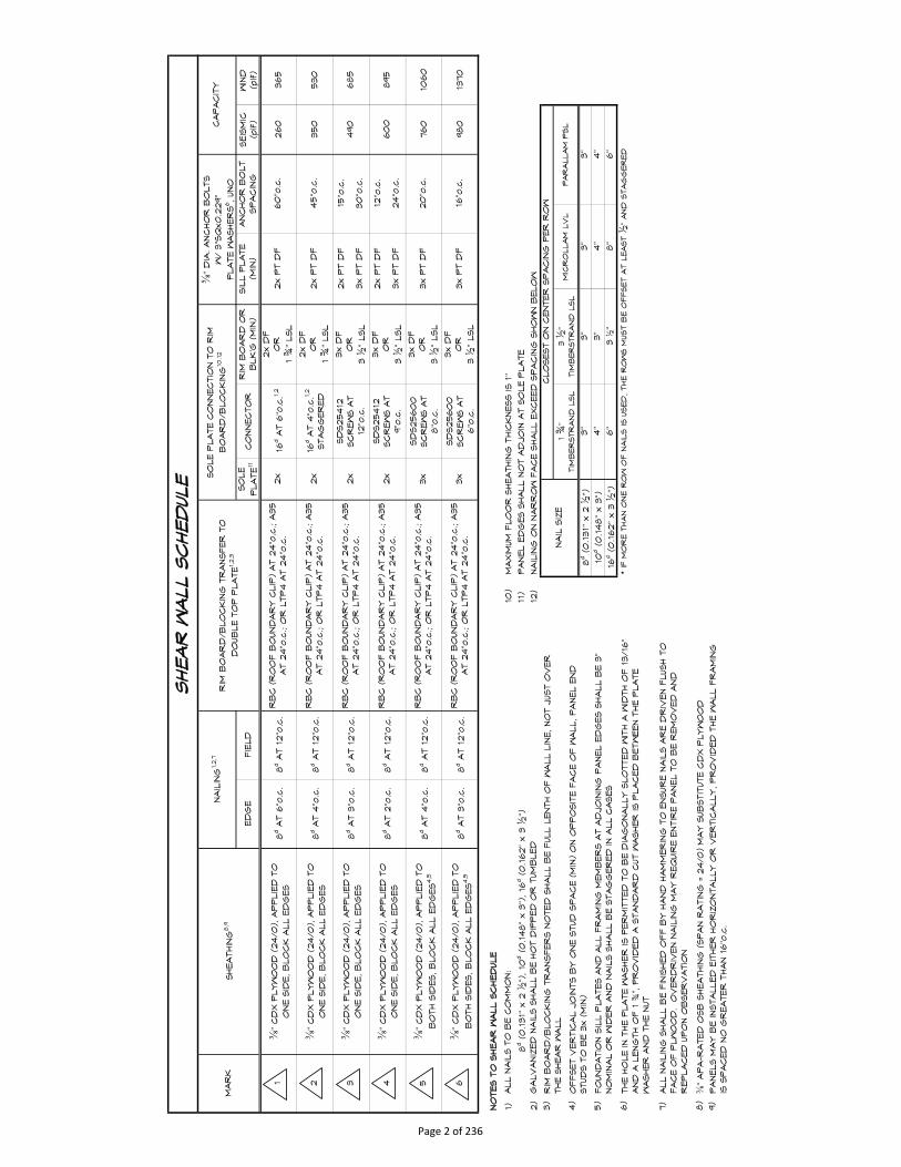
NO
TES T
O S
HEAR
WALL S
CHED
ULE
1)10
)M
AXIM
UM F
LO
OR
SHEATHIN
G T
HIC
KNESS IS 1
"
8d (
0.131"
x 2
½")
, 10
d (
0.148" x 3
"), 16
d (
0.162" x 3
½")
11)
PANEL E
DG
ES S
HALL N
OT A
DJO
IN A
T S
OLE P
LATE
2)
12)
NAIL
ING
ON N
AR
RO
W F
AC
E S
HALL E
XC
EED
SPAC
ING
SHO
WN B
ELO
W
3)
4)
5)
6)
* IF
MO
RE T
HAN O
NE R
OW
OF N
AIL
S IS U
SED
, THE R
OW
S M
UST B
E O
FFSET A
T L
EAST ½
" AND
STAG
GER
ED
7) 8)
9)
16d (
0.162" x 3
½")
NAIL
SIZ
E1 ¾
"TIM
BER
STR
AND
LSL
3"
4"
6"
3 ½
"TIM
BER
STR
AND
LSL
3"
3"
3 ½
"
MIC
RO
LLAM
LV
L
ALL N
AIL
ING
SHALL B
E F
INIS
HED
OFF B
Y H
AND
HAM
MER
ING
TO
ENSUR
E N
AIL
S A
RE D
RIV
EN F
LUS
H T
O
FAC
E O
F P
LW
OO
D. O
VER
DR
IVEN N
AIL
ING
MAY R
EQ
UIR
E E
NTIR
E P
ANEL T
O B
E R
EM
OV
ED
AND
R
EPLAC
ED
UPO
N O
BSER
VATIO
N
⅜" APA-R
ATED
OSB
SHEATHIN
G (
SPAN R
ATIN
G =
24/0
) M
AY S
UBSTIT
UTE C
DX P
LYW
OO
D
PANELS M
AY B
E INSTALLED
EIT
HER
HO
RIZ
ONTALLY O
R V
ER
TIC
ALLY, PR
OV
IDED
THE W
ALL F
RAM
ING
IS
SPAC
ED
NO
GR
EATER
THAN 1
6"o
.c.
8d (
0.131"
x 2
½")
10d (
0.148" x 3
")
SHEAR
WALL S
CHED
ULE
ALL N
AIL
S T
O B
E C
OM
MO
N:
GALV
ANIZ
ED
NAIL
S S
HALL B
E H
OT D
IPPED
OR
TUM
BLED
RIM
BO
AR
D/B
LO
CKIN
G T
RANSFER
S N
OTED
SHALL B
E F
ULL L
ENTH O
F W
ALL L
INE, NO
T J
UST O
VER
THE S
HEAR
WALL
PAR
ALLAM
PSL
CLO
SEST O
N C
ENTER
SPAC
ING
PER
RO
W20
"o.c
.
16"o
.c.
⅝" D
IA. ANC
HO
R B
OLTS
W/
3"S
Qx0
.229"
PLATE W
ASHER
S6, UN
O
3x
3x
MAR
K
1 2
SO
LE
PLATE
11
2x
2x
SHEATHIN
G8,9
CAPAC
ITY
3"
4"
8"
3"
4"
6"
60
"o.c
.
45"o
.c.
15"o
.c.
30
"o.c
.
12"o
.c.
RIM
BO
AR
D O
R
BLK'G
(M
IN)
2x D
FO
R1 ¾
" LSL
2x D
FO
R1 ¾
" LSL
OFFSET V
ER
TIC
AL J
OIN
TS B
Y O
NE S
TUD
SPAC
E (
MIN
) O
N O
PPO
SIT
E F
AC
E O
F W
ALL, PANEL E
ND
STUD
S T
O B
E 3
x (
MIN
)
FO
UND
ATIO
N S
ILL P
LATES A
ND
ALL F
RAM
ING
MEM
BER
S A
T A
DJO
ININ
G P
ANEL E
DG
ES S
HALL B
E 3
" NO
MIN
AL O
R W
IDER
AND
NAIL
S S
HALL B
E S
TAG
GER
ED
IN A
LL C
ASES
THE H
OLE IN T
HE P
LATE W
ASHER
IS P
ER
MIT
TED
TO
BE D
IAG
ONALLY S
LO
TTED
WIT
H A
WID
TH O
F 1
3/1
6"
AND
A L
ENG
TH O
F 1
¾", P
RO
VID
ED
A S
TAND
AR
D C
UT W
ASHER
IS P
LAC
ED
BETW
EEN T
HE P
LATE
WASHER
AND
THE N
UT
3 4 5 6
RB
C (
RO
OF B
OUN
DAR
Y C
LIP
) AT 2
4"o
.c.; A
35
AT 2
4"o
.c.; O
R L
TP4 A
T 2
4"o
.c.
RB
C (
RO
OF B
OUN
DAR
Y C
LIP
) AT 2
4"o
.c.; A
35
AT 2
4"o
.c.; O
R L
TP4 A
T 2
4"o
.c.
RB
C (
RO
OF B
OUN
DAR
Y C
LIP
) AT 2
4"o
.c.; A
35
AT 2
4"o
.c.; O
R L
TP4 A
T 2
4"o
.c.
SD
S25412
SC
REW
S A
T
12"o
.c.
3x D
FO
R3 ½
" LSL
3x D
FO
R3 ½
" LSL
3x P
T D
F
3x P
T D
F
⅜" C
DX P
LYW
OO
D (
24/0
), A
PPLIE
D T
OO
NE S
IDE, B
LO
CK A
LL E
DG
ES
SD
S25412
SC
REW
S A
T9"o
.c.
60
0895
2x
3x D
FO
R3 ½
" LSL
3x D
FO
R3 ½
" LSL
2x P
T D
F
3x P
T D
F
2x P
T D
F
3x P
T D
F24"o
.c.
⅜" C
DX P
LYW
OO
D (
24/0
), A
PPLIE
D T
OO
NE S
IDE, B
LO
CK A
LL E
DG
ES
8d A
T 3
"o.c
.8
d A
T 1
2"o
.c.
RB
C (
RO
OF B
OUN
DAR
Y C
LIP
) AT 2
4"o
.c.; A
35
AT 2
4"o
.c.; O
R L
TP4 A
T 2
4"o
.c.
RB
C (
RO
OF B
OUN
DAR
Y C
LIP
) AT 2
4"o
.c.; A
35
AT 2
4"o
.c.; O
R L
TP4 A
T 2
4"o
.c.
RIM
BO
AR
D/B
LO
CKIN
G T
RANSFER
TO
D
OUB
LE T
OP P
LATE
1,2,3
8d A
T 2
"o.c
.8
d A
T 1
2"o
.c.
RB
C (
RO
OF B
OUN
DAR
Y C
LIP
) AT 2
4"o
.c.; A
35
AT 2
4"o
.c.; O
R L
TP4 A
T 2
4"o
.c.
2x
490
685
NAIL
ING
1,2,7
SO
LE P
LATE C
ONNEC
TIO
N T
O R
IM
BO
AR
D/B
LO
CKIN
G10
,12
SIL
L P
LATE
(MIN
)
2x P
T D
F
2x P
T D
F
ANC
HO
R B
OLT
SPAC
ING
Page 2 of 236

FRAMING ANALYSIS
Page 3 of 236

Shawn Pierce Engineering
277 N. Beechnut Ave
Nipomo, CA 93444
Phone No.: (805) 801-9385
Email: [email protected]
Building Unit Weights
Main Floor Int. Walls Ceiling
(psf) (psf) (psf)
Plywood
Floor (1-1/8" Plywood) 3.5 --- ---
Walls (3/8" Plywood) --- 1.2 ---
Framing Members
Floor (18" I-Joists (Max) at 16"o.c.) 3.2 --- ---
Walls (2x6 at 16"o.c.) --- 4.0 ---
Ceiling (2x6 at 16"o.c., where applicable) --- --- 4.0
Ceiling
Dropped Panel Ceiling 2.0 --- ---
5/8" Gyp Board --- --- 2.8
Finishes
Carpet or 1/4" Tile 2.0 --- ---
1/2" Gyp Board --- 4.4 ---
Insulation 1.0 0.3 0.3
Mechanical/Electrical/Plumbing 1.0 0.1 0.2
Miscellaneous 1.3 --- 0.2
Dead Loads 14.0 10.0 7.5
Live Load 50.0 --- 10.0
*
*
* Live Load has been reduced for the Roof Framing per ASCE 7-05, Section 4.9
Material
All Dead Loads have been derived from either the ASCE 7-05 "Minimum Design Dead
Loads" Table C3-1, or per the manufacturer specs
All Live Loads have been derived from the ASCE 7-05 "Minimum Uniformly Distributed
Live Loads…" Table 4-1
Page 4 of 236
Page 5 of 236
Multiple Simple Beam Design ENERCALC, INC. 1983-2010, Ver: 6.1.03, N:40336License Owner : PIERCE ENGINEERINGLic. # : KW-06008640
File: Z:\@Shawn Pierce Engineering\09_Projects\Borzal Addition_02\Engineering\Design\melford borzall expansion.ec6Printed: 27 APR 2010, 11:55AM
Shawn Pierce Engineering277 N. Beechnut AveNipomo, CA 93444Phone: (805) 801-9385Email: [email protected]
Title : Melford Borzall Expansion Job # 09.9-2/2
Project Desc.:Dsgnr: Shawn D. Pierce
Project Notes :
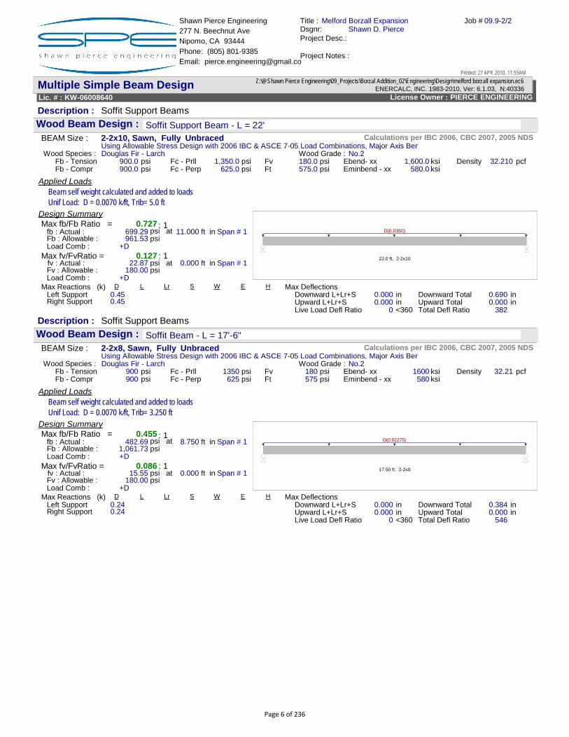
Soffit Support BeamsDescription :
BEAM Size : 2-2x10, Sawn, Fully UnbracedUsing Allowable Stress Design with 2006 IBC & ASCE 7-05 Load Combinations, Major Axis Bending
Wood Beam Design :Calculations per IBC 2006, CBC 2007, 2005 NDS
Douglas Fir - Larch No.2900.0900.0
1,350.0625.0
1,600.0580.0
180.0575.0
32.210Eminbend - xx ksi
Wood Species : Wood Grade :Fb - Tension
psipsi Fv psi
Fb - Compr Ft psiFc - Prll psi
psiFc - PerpEbend- xx ksi Density pcf
Soffit Support Beam - L = 22'
Applied LoadsBeam self weight calculated and added to loadsUnif Load: D = 0.0070 k/ft, Trib= 5.0 ft
.Design Summary
22.0 ft, 2-2x10
D(0.0350)Max fb/Fb Ratio = 0.727 : 1
Max Reactions (k) HEWSLrL
+DLoad Comb :
Span # 1
Left SupportD
in
11.000 inft
22.87 psi
Fb : Allowable : 961.53 psi
Right Support
Fv : Allowable :Span # 1
Load Comb : +D 180.00 psi
fb : Actual :
Max fv/FvRatio = 0.127 : 1 0.000 ft
699.29 psi at
atfv : Actual :
Live Load Defl Ratio 0 <360 Total Defl Ratio 382
Max DeflectionsDownward L+Lr+S 0.000 inUpward L+Lr+S 0.000 in
Downward Total 0.690 inUpward Total 0.000 in
0.45 0.45
Soffit Support BeamsDescription :
BEAM Size : 2-2x8, Sawn, Fully UnbracedUsing Allowable Stress Design with 2006 IBC & ASCE 7-05 Load Combinations, Major Axis Bending
Wood Beam Design :Calculations per IBC 2006, CBC 2007, 2005 NDS
Douglas Fir - Larch No.2900900
1350625
1600580
180575
32.21Eminbend - xx ksi
Wood Species : Wood Grade :Fb - Tension
psipsi Fv psi
Fb - Compr Ft psiFc - Prll psi
psiFc - PerpEbend- xx ksi Density pcf
Soffit Beam - L = 17'-6"
Applied LoadsBeam self weight calculated and added to loadsUnif Load: D = 0.0070 k/ft, Trib= 3.250 ft
.Design Summary
17.50 ft, 2-2x8
D(0.02275)Max fb/Fb Ratio = 0.455 : 1
Max Reactions (k) HEWSLrL
+DLoad Comb :
Span # 1
Left SupportD
in
8.750 inft
15.55 psi
Fb : Allowable : 1,061.73 psi
Right Support
Fv : Allowable :Span # 1
Load Comb : +D 180.00 psi
fb : Actual :
Max fv/FvRatio = 0.086 : 1 0.000 ft
482.69 psi at
atfv : Actual :
Live Load Defl Ratio 0 <360 Total Defl Ratio 546
Max DeflectionsDownward L+Lr+S 0.000 inUpward L+Lr+S 0.000 in
Downward Total 0.384 inUpward Total 0.000 in
0.24 0.24
Page 6 of 236

FRAMING ANALYSIS
Office Expansion
Page 7 of 236

Page 8 of 236

PROJECT INFORMATION:
Borzall Expansion
Santa Maria, CA
OPERATOR INFORMATION:
Michael Hayley
RedBuilt, LLC
3189 East Highway 46
Paso Robles, CA 93446
Phone : (805) 227-6633
Fax : (805) 227-6633
Typical Floor Joist = 18" Red-I65 at 16" o.c.
18" TJI®/L65 @ 16" o/cTJ-Beam® 6.35 Serial Number: 7005119916
User: 3 11/16/2009 1:40:23 PM
Page 1 Engine Version: 6.35.0THIS PRODUCT MEETS OR EXCEEDS THE SET DESIGN
CONTROLS FOR THE APPLICATION AND LOADS LISTED
LOADS:
Analysis is for a Joist Member.
Primary Load Group - Office Bldgs - Offices (psf): 50.0 Live at 100 % duration, 14.0 Dead, 20.0 Partition
SUPPORTS:
Input
Width
Bearing
Length
Vertical Reactions (lbs)
Live/Dead/Uplift/Total
Detail Other
1 Stud wall 3.50" 2.25" 767 / 521 / 0 / 1288 End, Rim 1 Ply 1 1/4" x 18" 1.3E TimberStrand® LSL
2 Stud wall 3.50" 2.25" 767 / 521 / 0 / 1288 End, Rim 1 Ply 1 1/4" x 18" 1.3E TimberStrand® LSL
DESIGN CONTROLS:
Maximum Design Control Result Location
Shear (lbs) 1265 -1255 2535 Passed (50%) Rt. end Span 1 under Floor loading
Vertical Reaction (lbs) 1265 1265 1535 Passed (82%) Bearing 2 under Floor loading
Moment (Ft-Lbs) 7140 7140 10380 Passed (69%) MID Span 1 under Floor loading
Live Load Defl (in) 0.323 0.452 Passed (L/839) MID Span 1 under Floor loading
Total Load Defl (in) 0.543 1.129 Passed (L/499) MID Span 1 under Floor loading
TJPro 47 45 Passed Span 1
-Deflection Criteria: STANDARD(LL:L/600,TL:L/240).
-Deflection analysis is based on composite action with single layer of 23/32" Panels (24" Span Rating) GLUED & NAILED wood decking.
-Bracing(Lu): All compression edges (top and bottom) must be braced at 4' 5" o/c unless detailed otherwise. Proper attachment and positioning of lateral bracing is required to achieve member stability.
-2000 lbs concentrated load requirements for standard non-residential floors have been considered for reaction and shear.
TJ-Pro RATING SYSTEM
-The TJ-Pro Rating System value provides additional floor performance information and is based on a GLUED & NAILED 23/32" Panels (24" Span Rating) decking. The controlling span is supported by walls. Additional considerations for this rating include: Ceiling - Suspended Ceiling. A structural analysis of the deck has not been performed by the program. Comparison Value: 2.2
ADDITIONAL NOTES:
-IMPORTANT! The analysis presented is output from software developed by iLevel®. Allowable product values shown are in accordance with current iLevel® materials and code accepted design values. The specific product application, input design loads and stated dimensions have been provided by others (____________________________________), have not been checked for conformance with the design drawings of the building, and have not been reviewed by iLevel® Engineering.
-THIS ANALYSIS FOR iLevel® PRODUCTS ONLY! PRODUCT SUBSTITUTION VOIDS THIS ANALYSIS.
-Allowable Stress Design methodology was used for Building Code IBC analyzing the iLevel® Custom product listed above.
Copyright © 2009 by iLevel®, Federal Way, WA.TJI® and TJ-Beam® are registered trademarks of iLevel®.e-I Joist™,Pro™ and TJ-Pro™ are trademarks of iLevel®.
D:\Documents and Settings\hayleymrb\My Documents\Mike\Jobs\09\Borzall Expansion - Santa Maria\Typical Floor Joist.sms
Page 9 of 236

Wood Beam Design ENERCALC, INC. 1983-2009, Ver: 6.0.24, N:40336License Owner : PIERCE ENGINEERINGLic. # : KW-06008640
File: Z:\@Shawn Pierce Engineering\09_Projects\Borzal Addition_02\Engineering\Design\melford borzall expansion.ec6Printed: 17 NOV 2009, 1:46PM
Description : FB-1 - Typ Floor Header at Office
Shawn Pierce Engineering277 N. Beechnut AveNipomo, CA 93444Phone: (805) 801-9385Email: [email protected]
Title : Melford Borzall Expansion Job # 09.9-2/2
Project Desc.:Dsgnr: Shawn D. Pierce
Project Notes :
Material Properties
Beam Bracing :
Calculations per IBC 2006, CBC 2007, 2005 NDS
Completely Unbraced
Allowable Stress Design
Douglas Fir - LarchNo.2
875.0875.0600.0625.0
1,300.0470.0
170.0425.0 32.210
Analysis Method :
Eminbend - xx ksiWood Species :Wood Grade :
Fb - Tensionpsipsi
Fv psi
Fb - Compr
Ft psi
Fc - Prll psipsiFc - Perp
E : Modulus of ElasticityEbend- xx ksi
Density pcf
Load Combination :2006 IBC & ASCE 7-05
6x10
Span = 4.50 ft
D(0.161) L(0.575)D(1.125)
.Applied Loads Service loads entered. Load Factors will be applied for calculations.
Beam self weight calculated and added to loadsLoad for Span Number 1
Uniform Load : D = 0.0140, L = 0.050 ksf, Tributary Width = 11.50 ftUniform Load : D = 0.090 ksf, Tributary Width = 12.50 ft
.DESIGN SUMMARY Design OKMaximum Bending Stress Ratio 0.787: 1
Load Combination +D+L+H
Span # where maximum occurs Span # 1Location of maximum on span 2.250ft
78.63 psi=
=
FB : Allowable 873.83psi Fv : Allowable
6x10Section used for this span
Span # where maximum occursLocation of maximum on span
Span # 1=
Load Combination +D+L+H=
=
=
170.00 psi==
Section used for this span 6x10fb : Actual
Maximum Shear Stress Ratio 0.463 : 1
3.713 ft==
687.58psi fv : Actual
Maximum Deflection
0 <4801583
Ratio = 0 <360
Max Downward L+Lr+S Deflection 0.010 in 5158Ratio =Max Upward L+Lr+S Deflection 0.000 in Ratio =Max Downward Total Deflection 0.034 in Ratio =Max Upward Total Deflection 0.000 in
.Maximum Forces & Stresses for Load Combinations
Span #Summary of Moment ValuesLoad Combination
d
Summary of Shear ValuesMax Stress RatiosM CV fb-designMactual fv-designFb-allow Vactual Fv-allowSegment Length
+D Length = 4.50 ft 1 0.545 0.320 1.000 3.28 476.46 873.83 1.90 170.00 54.48+D+L+H Length = 4.50 ft 1 0.787 0.463 1.000 4.74 687.58 873.83 2.74 170.00 78.63+D+Lr+H Length = 4.50 ft 1 0.545 0.320 1.000 3.28 476.46 873.83 1.90 170.00 54.48+D+0.750Lr+0.750L+H Length = 4.50 ft 1 0.726 0.427 1.000 4.38 634.80 873.83 2.53 170.00 72.59
.Location in SpanLoad CombinationMax. "-" Defl Location in SpanLoad Combination Span Max. "+" Defl
Overall Maximum Deflections - Unfactored Loads
D+L+Lr 1 0.0341 2.273 0.0000 0.000.
Page 10 of 236

Wood Beam Design ENERCALC, INC. 1983-2009, Ver: 6.0.24, N:40336License Owner : PIERCE ENGINEERINGLic. # : KW-06008640
File: Z:\@Shawn Pierce Engineering\09_Projects\Borzal Addition_02\Engineering\Design\melford borzall expansion.ec6Printed: 17 NOV 2009, 1:46PM
Description : FB-2 - Floor Header at Office - L=9'-6"
Shawn Pierce Engineering277 N. Beechnut AveNipomo, CA 93444Phone: (805) 801-9385Email: [email protected]
Title : Melford Borzall Expansion Job # 09.9-2/2
Project Desc.:Dsgnr: Shawn D. Pierce
Project Notes :
Material Properties
Beam Bracing :
Calculations per IBC 2006, CBC 2007, 2005 NDS
Completely Unbraced
Allowable Stress Design
iLevel Truss JoistMicroLam LVL 1.9 E
2,600.02,600.02,510.0
750.0
1,900.01,900.0
285.01,555.0 32.210
Analysis Method :
Eminbend - xx ksiWood Species :Wood Grade :
Fb - Tensionpsipsi
Fv psi
Fb - Compr
Ft psi
Fc - Prll psipsiFc - Perp
E : Modulus of ElasticityEbend- xx ksi
Density pcf
Load Combination :2006 IBC & ASCE 7-05
5.250x11.875
Span = 9.50 ft
D(0.161) L(0.575)D(1.125)
.Applied Loads Service loads entered. Load Factors will be applied for calculations.
Beam self weight calculated and added to loadsLoad for Span Number 1
Uniform Load : D = 0.0140, L = 0.050 ksf, Tributary Width = 11.50 ftUniform Load : D = 0.090 ksf, Tributary Width = 12.50 ft
.DESIGN SUMMARY Design OKMaximum Bending Stress Ratio 0.796: 1
Load Combination +D+L+H
Span # where maximum occurs Span # 1Location of maximum on span 4.750ft
171.42 psi=
=
FB : Allowable 2,584.11psi Fv : Allowable
5.250x11.875Section used for this span
Span # where maximum occursLocation of maximum on span
Span # 1=
Load Combination +D+L+H=
=
=
285.00 psi==
Section used for this span 5.250x11.875fb : Actual
Maximum Shear Stress Ratio 0.601 : 1
0.000 ft==
2,057.08psi fv : Actual
Maximum Deflection
0 <480458
Ratio = 0 <360
Max Downward L+Lr+S Deflection 0.076 in 1493Ratio =Max Upward L+Lr+S Deflection 0.000 in Ratio =Max Downward Total Deflection 0.249 in Ratio =Max Upward Total Deflection 0.000 in
.Maximum Forces & Stresses for Load Combinations
Span #Summary of Moment ValuesLoad Combination
d
Summary of Shear ValuesMax Stress RatiosM CV fb-designMactual fv-designFb-allow Vactual Fv-allowSegment Length
+D Length = 9.50 ft 1 0.552 0.417 1.000 14.67 1,426.23 2,584.11 4.94 285.00 118.85+D+L+H Length = 9.50 ft 1 0.796 0.601 1.000 21.15 2,057.08 2,584.11 7.12 285.00 171.42+D+Lr+H Length = 9.50 ft 1 0.552 0.417 1.000 14.67 1,426.23 2,584.11 4.94 285.00 118.85+D+0.750Lr+0.750L+H Length = 9.50 ft 1 0.735 0.555 1.000 19.53 1,899.37 2,584.11 6.58 285.00 158.28
.Location in SpanLoad CombinationMax. "-" Defl Location in SpanLoad Combination Span Max. "+" Defl
Overall Maximum Deflections - Unfactored Loads
D+L+Lr 1 0.2488 4.798 0.0000 0.000.
Page 11 of 236
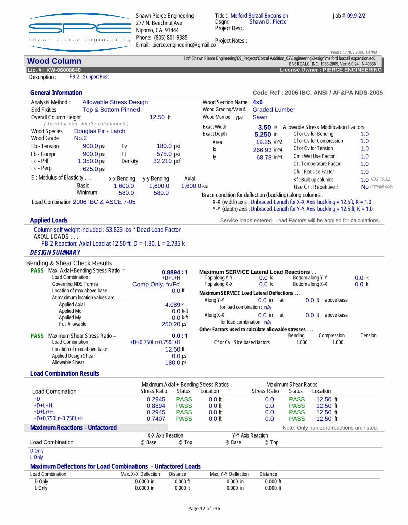
Wood Column ENERCALC, INC. 1983-2009, Ver: 6.0.24, N:40336License Owner : PIERCE ENGINEERINGLic. # : KW-06008640
File: Z:\@Shawn Pierce Engineering\09_Projects\Borzal Addition_02\Engineering\Design\melford borzall expansion.ec6Printed: 17 NOV 2009, 1:47PM
Description : FB-2 - Support Post
Shawn Pierce Engineering277 N. Beechnut AveNipomo, CA 93444Phone: (805) 801-9385Email: [email protected]
Title : Melford Borzall Expansion Job # 09.9-2/2
Project Desc.:Dsgnr: Shawn D. Pierce
Project Notes :
.General InformationWood Section Name
Code Ref : 2006 IBC, ANSI / AF&PA NDS-2005
4x6Analysis Method :
12.50Overall Column Height ft
Allowable Stress Design
( Used for non-slender calculations ) Allowable Stress Modification Factors
End Fixities Top & Bottom Pinned
Wood Species Douglas Fir - LarchWood Grade No.2Fb - Tension 900.0
900.0 psi1,350.0
625.0
180.0575.0
32.210
psi Fv psiFb - Compr Ft psiFc - Prll psi
psiDensity pcf
Fc - PerpE : Modulus of Elasticity . . .
1,600.0580.0
1,600.0580.0
Cfu : Flat Use Factor 1.0
Cf or Cv for Tension 1.0
Use Cr : Repetitive ?Kf : Built-up columns 1.0
(non-glb only)NDS 15.3.2
Exact Width 3.50 inExact Depth 5.250 in
Area 19.25 in^2Ix 266.93 in^4Iy 68.78 in^4
Wood Grading/Manuf. Graded LumberWood Member Type Sawn
Ct : Temperature Factor 1.0
Cf or Cv for Compression 1.0
1,600.0Axial
Cm : Wet Use Factor 1.0
Cf or Cv for Bending 1.0
x-x Bending y-y Bendingksi No
MinimumBasic
Y-Y (depth) axis :X-X (width) axis :
Unbraced Length for Y-Y Axis buckling = 12.5 ft, K = 1.0Unbraced Length for X-X Axis buckling = 12.5ft, K = 1.0
Brace condition for deflection (buckling) along columns :Load Combination :2006 IBC & ASCE 7-05
.Service loads entered. Load Factors will be applied for calculations.Applied LoadsColumn self weight included : 53.823 lbs * Dead Load FactorAXIAL LOADS . . . FB-2 Reaction: Axial Load at 12.50 ft, D = 1.30, L = 2.735 k
.DESIGN SUMMARY
PASS
PASS
Max. Axial+Bending Stress Ratio = 0.8894
Location of max.above base 0.0 ft
Applied Axial 4.089 kApplied Mx 0.0 k-ft
Load Combination +D+L+H
Load Combination +D+0.750Lr+0.750L+H
Bending & Shear Check Results
Maximum Shear Stress Ratio =
Applied Design Shear 0.0 psi180.0Allowable Shear
1.000 1.000
psi
0.0 : 1 Bending Compression TensionCf or Cv : Size based factors
Location of max.above base 12.50 ft
: 1
At maximum location values are . . .
Applied My 0.0 k-ft
Maximum SERVICE Lateral Load Reactions . .Top along Y-Y 0.0 k Bottom along Y-Y 0.0 kTop along X-X 0.0 k Bottom along X-X 0.0 kGoverning NDS Formla Comp Only, fc/Fc'
Maximum SERVICE Load Lateral Deflections . . .Along Y-Y 0.0 in at 0.0 ft above base
for load combination : n/aAlong X-X 0.0 in at 0.0 ft above base
Fc : Allowable 250.20 psiOther Factors used to calculate allowable stresses . . .
for load combination : n/a
.
Load Combination Stress Ratio Location Stress Ratio Status LocationStatusMaximum Axial + Bending Stress Ratios Maximum Shear Ratios
Load Combination Results
+D PASS PASS0.0 0.0 12.50 ftft0.2945+D+L+H PASS PASS0.0 0.0 12.50 ftft0.8894+D+Lr+H PASS PASS0.0 0.0 12.50 ftft0.2945+D+0.750Lr+0.750L+H PASS PASS0.0 0.0 12.50 ftft0.7407
.Note: Only non-zero reactions are listed.
Load CombinationX-X Axis Reaction Y-Y Axis Reaction
@ Base @ Top @ Base @ Top
Maximum Reactions - Unfactored
D OnlyL Only
.Max. X-X Deflection Max. Y-Y Deflection DistanceLoad Combination
Maximum Deflections for Load Combinations - Unfactored LoadsDistance
D Only 0.0000 0.000 0.000 ftft inin 0.000L Only 0.0000 0.000 0.000 ftft inin 0.000
.
Page 12 of 236

Page 13 of 236

Wood Beam Design ENERCALC, INC. 1983-2009, Ver: 6.1.01, N:40336License Owner : PIERCE ENGINEERINGLic. # : KW-06008640
File: Y:\@Shawn Pierce Engineering\09_Projects\Borzal Addition_02\Engineering\Design\melford borzall expansion.ec6Printed: 6 JAN 2010, 8:01AM
Description : FB-3 - Floor Header at Office - L=13'-6"
Shawn Pierce Engineering277 N. Beechnut AveNipomo, CA 93444Phone: (805) 801-9385Email: [email protected]
Title : Melford Borzall Expansion Job # 09.9-2/2
Project Desc.:Dsgnr: Shawn D. Pierce
Project Notes :
Material Properties
Beam Bracing :
Calculations per IBC 2006, CBC 2007, 2005 NDS
Completely Unbraced
Allowable Stress Design
iLevel Truss JoistParallam PSL 2.0E
2,900.02,900.02,900.0
750.0
2,000.02,000.0
290.02,025.0 32.210
Analysis Method :
Eminbend - xx ksiWood Species :Wood Grade :
Fb - Tensionpsipsi
Fv psi
Fb - Compr
Ft psi
Fc - Prll psipsiFc - Perp
E : Modulus of ElasticityEbend- xx ksi
Density pcf
Load Combination :2006 IBC & ASCE 7-05
5.25x14.0
Span = 13.50 ft
D(0.94) L(1.98) D(0.94) L(1.98)
D(0.161) L(0.575)D(0.1125)
D(0.042) L(0.15)D(0.161) L(0.575)
.Applied Loads Service loads entered. Load Factors will be applied for calculations.
Beam self weight calculated and added to loadsLoad for Span Number 1
Uniform Load : D = 0.0140, L = 0.050 ksf, Extent = 0.0 -->> 5.50 ft, Tributary Width = 11.50 ftUniform Load : D = 0.0090 ksf, Tributary Width = 12.50 ftUniform Load : D = 0.0140, L = 0.050 ksf, Extent = 5.50 -->> 11.50 ft, Tributary Width = 3.0 ftUniform Load : D = 0.0140, L = 0.050 ksf, Extent = 11.50 -->> 13.50 ft, Tributary Width = 11.50 ftPoint Load : D = 0.940, L = 1.980 k @ 5.50 ft, (FB-6)Point Load : D = 0.940, L = 1.980 k @ 11.50 ft, (FB-6)
.DESIGN SUMMARY Design OKMaximum Bending Stress Ratio 0.592: 1
Load Combination +D+L+H
Span # where maximum occurs Span # 1Location of maximum on span 5.535ft
132.00 psi=
=
FB : Allowable 2,865.66psi Fv : Allowable
5.25x14.0Section used for this span
Span # where maximum occursLocation of maximum on span
Span # 1=
Load Combination +D+L+H=
=
=
290.00 psi==
Section used for this span 5.25x14.0fb : Actual
Maximum Shear Stress Ratio 0.455 : 1
12.353 ft==
1,696.44psi fv : Actual
Maximum Deflection
0 <480505
Ratio = 0 <360
Max Downward L+Lr+S Deflection 0.203 in 797Ratio =Max Upward L+Lr+S Deflection 0.000 in Ratio =Max Downward Total Deflection 0.320 in Ratio =Max Upward Total Deflection 0.000 in
.Maximum Forces & Stresses for Load Combinations
Span #Summary of Moment ValuesLoad Combination
d
Summary of Shear ValuesMax Stress RatiosM CV fb-designMactual fv-designFb-allow Vactual Fv-allowSegment Length
+D Length = 13.50 ft 1 0.214 0.166 1.000 8.75 612.15 2,865.66 2.36 290.00 48.13+D+L+H Length = 13.50 ft 1 0.592 0.455 1.000 24.24 1,696.44 2,865.66 6.47 290.00 132.00+D+Lr+H Length = 13.50 ft 1 0.214 0.166 1.000 8.75 612.15 2,865.66 2.36 290.00 48.13+D+0.750Lr+0.750L+H Length = 13.50 ft 1 0.497 0.383 1.000 20.37 1,425.37 2,865.66 5.44 290.00 111.03
.
Page 14 of 236

Wood Beam Design ENERCALC, INC. 1983-2009, Ver: 6.1.01, N:40336License Owner : PIERCE ENGINEERINGLic. # : KW-06008640
File: Y:\@Shawn Pierce Engineering\09_Projects\Borzal Addition_02\Engineering\Design\melford borzall expansion.ec6Printed: 6 JAN 2010, 8:01AM
Description : FB-3 - Floor Header at Office - L=13'-6"
Shawn Pierce Engineering277 N. Beechnut AveNipomo, CA 93444Phone: (805) 801-9385Email: [email protected]
Title : Melford Borzall Expansion Job # 09.9-2/2
Project Desc.:Dsgnr: Shawn D. Pierce
Project Notes :
Location in SpanLoad CombinationMax. "-" Defl Location in SpanLoad Combination Span Max. "+" DeflOverall Maximum Deflections - Unfactored Loads
D+L+Lr 1 0.3203 6.683 0.0000 0.000.
Load Combination Support 1 Support 2Vertical Reactions - Unfactored Support notation : Far left is #1 Values in KIPS
Overall MAXimum 6.792 7.460D Only 2.389 2.691L Only 4.403 4.769D+L+S 6.792 7.460D+L+Lr 6.792 7.460
Page 15 of 236

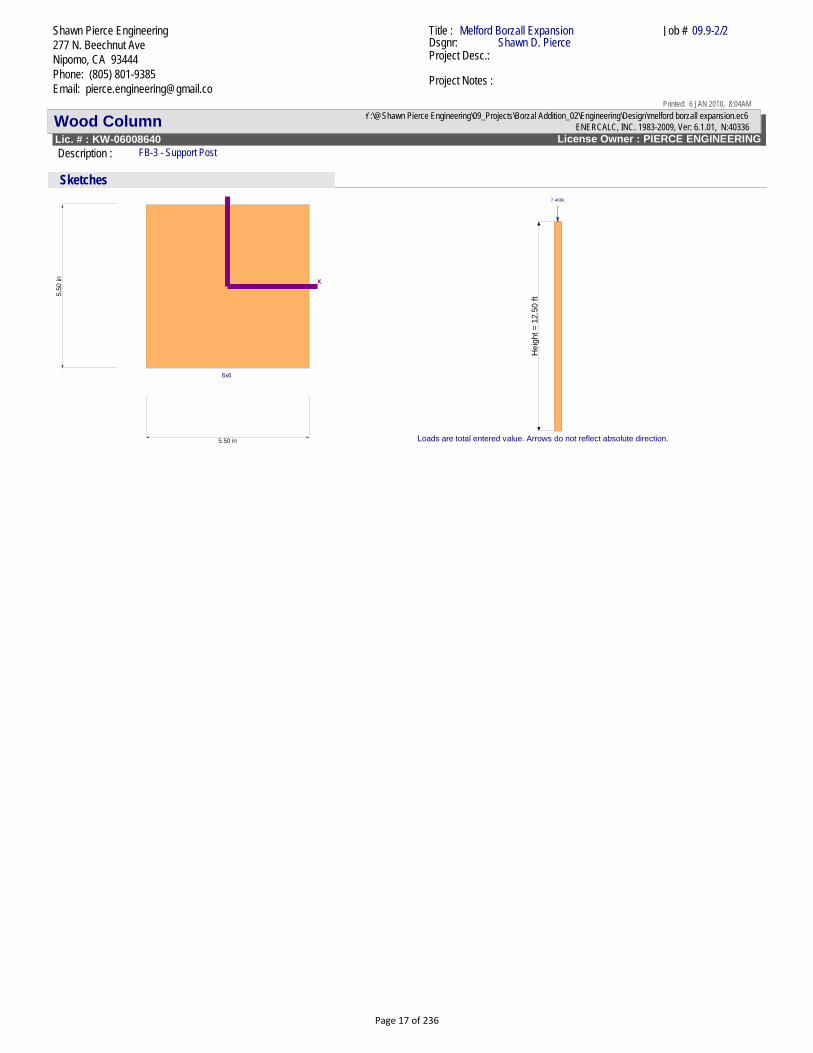
Wood Column ENERCALC, INC. 1983-2009, Ver: 6.1.01, N:40336License Owner : PIERCE ENGINEERINGLic. # : KW-06008640
File: Y:\@Shawn Pierce Engineering\09_Projects\Borzal Addition_02\Engineering\Design\melford borzall expansion.ec6Printed: 6 JAN 2010, 8:04AM
Description : FB-3 - Support Post
Shawn Pierce Engineering277 N. Beechnut AveNipomo, CA 93444Phone: (805) 801-9385Email: [email protected]
Title : Melford Borzall Expansion Job # 09.9-2/2
Project Desc.:Dsgnr: Shawn D. Pierce
Project Notes :
.General InformationWood Section Name
Code Ref : 2006 IBC, ANSI / AF&PA NDS-2005
6x6Analysis Method :
12.50Overall Column Height ft
Allowable Stress Design
( Used for non-slender calculations ) Allowable Stress Modification Factors
End Fixities Top & Bottom Pinned
Wood Species Douglas Fir - LarchWood Grade No.2Fb - Tension 750.0
750.0 psi700.0625.0
170.0475.0
32.210
psi Fv psiFb - Compr Ft psiFc - Prll psi
psiDensity pcf
Fc - PerpE : Modulus of Elasticity . . .
1,300.0470.0
1,300.0470.0
Cfu : Flat Use Factor 1.0
Cf or Cv for Tension 1.0
Use Cr : Repetitive ?Kf : Built-up columns 1.0
(non-glb only)NDS 15.3.2
Exact Width 5.50 inExact Depth 5.50 in
Area 30.250 in^2Ix 76.255 in^4Iy 76.255 in^4
Wood Grading/Manuf. Graded LumberWood Member Type Sawn
Ct : Temperature Factor 1.0
Cf or Cv for Compression 1.0
1,300.0Axial
Cm : Wet Use Factor 1.0
Cf or Cv for Bending 1.0
x-x Bending y-y Bendingksi No
MinimumBasic
Y-Y (depth) axis :X-X (width) axis :
Unbraced Length for Y-Y Axis buckling = 12.5 ft, K = 1.0Unbraced Length for X-X Axis buckling = 12.5ft, K = 1.0
Brace condition for deflection (buckling) along columns :Load Combination :2006 IBC & ASCE 7-05
.Service loads entered. Load Factors will be applied for calculations.Applied LoadsColumn self weight included : 84.579 lbs * Dead Load FactorAXIAL LOADS . . . FB-2 Reaction: Axial Load at 12.50 ft, D = 2.690, L = 4.770 k
.DESIGN SUMMARY
PASS
PASS
Max. Axial+Bending Stress Ratio = 0.6091
Location of max.above base 0.0 ft
Applied Axial 7.545 kApplied Mx 0.0 k-ft
Load Combination +D+L+H
Load Combination +D+0.750Lr+0.750L+H
Bending & Shear Check Results
Maximum Shear Stress Ratio =
Applied Design Shear 0.0 psi170.0Allowable Shear
1.000 1.000
psi
0.0 : 1 Bending Compression TensionCf or Cv : Size based factors
Location of max.above base 12.50 ft
: 1
At maximum location values are . . .
Applied My 0.0 k-ft
Maximum SERVICE Lateral Load Reactions . .Top along Y-Y 0.0 k Bottom along Y-Y 0.0 kTop along X-X 0.0 k Bottom along X-X 0.0 kGoverning NDS Formla Comp Only, fc/Fc'
Maximum SERVICE Load Lateral Deflections . . .Along Y-Y 0.0 in at 0.0 ft above base
for load combination : n/aAlong X-X 0.0 in at 0.0 ft above base
Fc : Allowable 409.44 psiOther Factors used to calculate allowable stresses . . .
for load combination : n/a
.
Load Combination Stress Ratio Location Stress Ratio Status LocationStatusMaximum Axial + Bending Stress Ratios Maximum Shear Ratios
Load Combination Results
+D PASS PASS0.0 0.0 12.50 ftft0.2240+D+L+H PASS PASS0.0 0.0 12.50 ftft0.6091+D+Lr+H PASS PASS0.0 0.0 12.50 ftft0.2240+D+0.750Lr+0.750L+H PASS PASS0.0 0.0 12.50 ftft0.5129
.Note: Only non-zero reactions are listed.
Load CombinationX-X Axis Reaction Y-Y Axis Reaction
@ Base @ Top @ Base @ Top
Maximum Reactions - Unfactored
D OnlyL Only
.Max. X-X Deflection Max. Y-Y Deflection DistanceLoad Combination
Maximum Deflections for Load Combinations - Unfactored LoadsDistance
D Only 0.0000 0.000 0.000 ftft inin 0.000L Only 0.0000 0.000 0.000 ftft inin 0.000
.
Page 16 of 236
Wood Column ENERCALC, INC. 1983-2009, Ver: 6.1.01, N:40336License Owner : PIERCE ENGINEERINGLic. # : KW-06008640
File: Y:\@Shawn Pierce Engineering\09_Projects\Borzal Addition_02\Engineering\Design\melford borzall expansion.ec6Printed: 6 JAN 2010, 8:04AM
Description : FB-3 - Support Post
Shawn Pierce Engineering277 N. Beechnut AveNipomo, CA 93444Phone: (805) 801-9385Email: [email protected]
Title : Melford Borzall Expansion Job # 09.9-2/2
Project Desc.:Dsgnr: Shawn D. Pierce
Project Notes :
Sketches
5.50
in
5.50 in
Y
XX
6x6
Hei
ght
= 1
2.50
ft
7.460k
Loads are total entered value. Arrows do not reflect absolute direction.
Page 17 of 236

Wood Beam Design ENERCALC, INC. 1983-2009, Ver: 6.0.24, N:40336License Owner : PIERCE ENGINEERINGLic. # : KW-06008640
File: Z:\@Shawn Pierce Engineering\09_Projects\Borzal Addition_02\Engineering\Design\melford borzall expansion.ec6Printed: 17 NOV 2009, 1:49PM
Description : FB-4 - Floor Beam - Line O
Shawn Pierce Engineering277 N. Beechnut AveNipomo, CA 93444Phone: (805) 801-9385Email: [email protected]
Title : Melford Borzall Expansion Job # 09.9-2/2
Project Desc.:Dsgnr: Shawn D. Pierce
Project Notes :
Material Properties
Beam Bracing :
Calculations per IBC 2006, CBC 2007, 2005 NDS
Beam is Fully Braced against lateral-torsion buckling
Allowable Stress Design
iLevel Truss JoistParallam PSL 2.0E
2,900.02,900.02,900.0
750.0
2,000.02,000.0
290.02,025.0 32.210
Analysis Method :
Eminbend - xx ksiWood Species :Wood Grade :
Fb - Tensionpsipsi
Fv psi
Fb - Compr
Ft psi
Fc - Prll psipsiFc - Perp
E : Modulus of ElasticityEbend- xx ksi
Density pcf
Load Combination :2006 IBC & ASCE 7-05
5.25x11.25
Span = 9.50 ft
D(0.196) L(0.7)
.Applied Loads Service loads entered. Load Factors will be applied for calculations.
Beam self weight calculated and added to loadsLoad for Span Number 1
Uniform Load : D = 0.0140, L = 0.050 ksf, Tributary Width = 14.0 ft.DESIGN SUMMARY Design OK
Maximum Bending Stress Ratio 0.383: 1
Load Combination +D+L+H
Span # where maximum occurs Span # 1Location of maximum on span 4.750ft
88.84 psi=
=
FB : Allowable 2,900.00psi Fv : Allowable
5.25x11.25Section used for this span
Span # where maximum occursLocation of maximum on span
Span # 1=
Load Combination +D+L+H=
=
=
290.00 psi==
Section used for this span 5.25x11.25fb : Actual
Maximum Shear Stress Ratio 0.306 : 1
0.000 ft==
1,111.45psi fv : Actual
Maximum Deflection
0 <480845
Ratio = 0 <360
Max Downward L+Lr+S Deflection 0.104 in 1098Ratio =Max Upward L+Lr+S Deflection 0.000 in Ratio =Max Downward Total Deflection 0.135 in Ratio =Max Upward Total Deflection 0.000 in
.Maximum Forces & Stresses for Load Combinations
Span #Summary of Moment ValuesLoad Combination
d
Summary of Shear ValuesMax Stress RatiosM CV fb-designMactual fv-designFb-allow Vactual Fv-allowSegment Length
+D Length = 9.50 ft 1 0.088 0.070 1.000 2.36 255.75 2,900.00 0.80 290.00 20.44+D+L+H Length = 9.50 ft 1 0.383 0.306 1.000 10.26 1,111.45 2,900.00 3.50 290.00 88.84+D+Lr+H Length = 9.50 ft 1 0.088 0.070 1.000 2.36 255.75 2,900.00 0.80 290.00 20.44+D+0.750Lr+0.750L+H Length = 9.50 ft 1 0.309 0.247 1.000 8.28 897.52 2,900.00 2.82 290.00 71.74
.Location in SpanLoad CombinationMax. "-" Defl Location in SpanLoad Combination Span Max. "+" Defl
Overall Maximum Deflections - Unfactored Loads
D+L+Lr 1 0.1348 4.798 0.0000 0.000.
Page 18 of 236
Page 19 of 236

Wood Beam Design ENERCALC, INC. 1983-2009, Ver: 6.1.01, N:40336License Owner : PIERCE ENGINEERINGLic. # : KW-06008640
File: Z:\@Shawn Pierce Engineering\09_Projects\Borzal Addition_02\Engineering\Design\melford borzall expansion.ec6Printed: 15 DEC 2009, 1:08PM
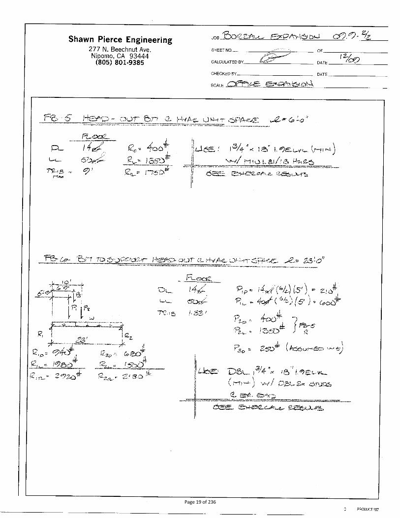
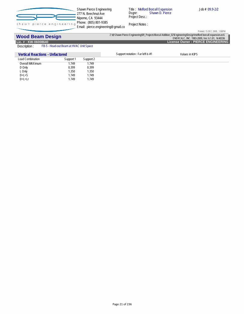
Description : FB-5 - Head-out Beam at HVAC Unit Space
Shawn Pierce Engineering277 N. Beechnut AveNipomo, CA 93444Phone: (805) 801-9385Email: [email protected]
Title : Melford Borzall Expansion Job # 09.9-2/2
Project Desc.:Dsgnr: Shawn D. Pierce
Project Notes :
Material Properties
Beam Bracing :
Calculations per IBC 2006, CBC 2007, 2005 NDS
Beam is Fully Braced against lateral-torsion buckling
Allowable Stress Design
iLevel Truss JoistMicroLam LVL 1.9 E
260026002510
750
1900965.71
2851555 32.21
Analysis Method :
Eminbend - xx ksiWood Species :Wood Grade :
Fb - Tensionpsipsi
Fv psi
Fb - Compr
Ft psi
Fc - Prll psipsiFc - Perp
E : Modulus of ElasticityEbend- xx ksi
Density pcf
Load Combination :2006 IBC & ASCE 7-05
1.75x18
Span = 6.0 ft
D(0.126) L(0.45)
.Applied Loads Service loads entered. Load Factors will be applied for calculations.
Beam self weight calculated and added to loadsLoad for Span Number 1
Uniform Load : D = 0.0140, L = 0.050 ksf, Tributary Width = 9.0 ft, (Floor).DESIGN SUMMARY Design OK
Maximum Bending Stress Ratio 0.128: 1
Load Combination +D+L+H
Span # where maximum occurs Span # 1Location of maximum on span 3.000ft
42.48 psi=
=
FB : Allowable 2,600.00psi Fv : Allowable
1.75x18Section used for this span
Span # where maximum occursLocation of maximum on span
Span # 1=
Load Combination +D+L+H=
=
=
285.00 psi==
Section used for this span 1.75x18fb : Actual
Maximum Shear Stress Ratio 0.149 : 1
4.530 ft==
333.17psi fv : Actual
Maximum Deflection
0 <4806789
Ratio = 0 <360
Max Downward L+Lr+S Deflection 0.008 in 8796Ratio =Max Upward L+Lr+S Deflection 0.000 in Ratio =Max Downward Total Deflection 0.011 in Ratio =Max Upward Total Deflection 0.000 in
.Maximum Forces & Stresses for Load Combinations
Span #Summary of Moment ValuesLoad Combination
d
Summary of Shear ValuesMax Stress RatiosM CV fb-designMactual fv-designFb-allow Vactual Fv-allowSegment Length
+D Length = 6.0 ft 1 0.029 0.034 1.000 0.60 76.03 2,600.00 0.20 285.00 9.69+D+L+H Length = 6.0 ft 1 0.128 0.149 1.000 2.62 333.17 2,600.00 0.89 285.00 42.48+D+Lr+H Length = 6.0 ft 1 0.029 0.034 1.000 0.60 76.03 2,600.00 0.20 285.00 9.69+D+0.750Lr+0.750L+H Length = 6.0 ft 1 0.103 0.120 1.000 2.12 268.88 2,600.00 0.72 285.00 34.28
.Location in SpanLoad CombinationMax. "-" Defl Location in SpanLoad Combination Span Max. "+" Defl
Overall Maximum Deflections - Unfactored Loads
D+L+Lr 1 0.0106 3.030 0.0000 0.000.
Page 20 of 236
Wood Beam Design ENERCALC, INC. 1983-2009, Ver: 6.1.01, N:40336License Owner : PIERCE ENGINEERINGLic. # : KW-06008640
File: Z:\@Shawn Pierce Engineering\09_Projects\Borzal Addition_02\Engineering\Design\melford borzall expansion.ec6Printed: 15 DEC 2009, 1:08PM
Description : FB-5 - Head-out Beam at HVAC Unit Space
Shawn Pierce Engineering277 N. Beechnut AveNipomo, CA 93444Phone: (805) 801-9385Email: [email protected]
Title : Melford Borzall Expansion Job # 09.9-2/2
Project Desc.:Dsgnr: Shawn D. Pierce
Project Notes :
Load Combination Support 1 Support 2Vertical Reactions - Unfactored Support notation : Far left is #1 Values in KIPS
Overall MAXimum 1.749 1.749D Only 0.399 0.399L Only 1.350 1.350D+L+S 1.749 1.749D+L+Lr 1.749 1.749
Page 21 of 236

Wood Beam Design ENERCALC, INC. 1983-2009, Ver: 6.1.01, N:40336License Owner : PIERCE ENGINEERINGLic. # : KW-06008640
File: Z:\@Shawn Pierce Engineering\09_Projects\Borzal Addition_02\Engineering\Design\melford borzall expansion.ec6Printed: 15 DEC 2009, 1:14PM
Description : FB-6 - Beam to Support Head out at HVAC Unit Space
Shawn Pierce Engineering277 N. Beechnut AveNipomo, CA 93444Phone: (805) 801-9385Email: [email protected]
Title : Melford Borzall Expansion Job # 09.9-2/2
Project Desc.:Dsgnr: Shawn D. Pierce
Project Notes :
Material Properties
Beam Bracing :
Calculations per IBC 2006, CBC 2007, 2005 NDS
Beam is Fully Braced against lateral-torsion buckling
Allowable Stress Design
iLevel Truss JoistMicroLam LVL 1.9 E
260026002510
750
1900965.71
2851555 32.21
Analysis Method :
Eminbend - xx ksiWood Species :Wood Grade :
Fb - Tensionpsipsi
Fv psi
Fb - Compr
Ft psi
Fc - Prll psipsiFc - Perp
E : Modulus of ElasticityEbend- xx ksi
Density pcf
Load Combination :2006 IBC & ASCE 7-05
3.5x18
Span = 23.0 ft
D(0.21) L(0.6) D(0.4) L(1.35)D(0.25)
D(0.01862) L(0.0665)
.Applied Loads Service loads entered. Load Factors will be applied for calculations.
Beam self weight calculated and added to loadsLoad for Span Number 1
Uniform Load : D = 0.0140, L = 0.050 ksf, Tributary Width = 1.330 ft, (Floor)Point Load : D = 0.210, L = 0.60 k @ 5.750 ft, (P1)Point Load : D = 0.40, L = 1.350 k @ 10.0 ft, (P2)Point Load : D = 0.250 k @ 6.750 ft, (P3 - Mechanical Uni)
.DESIGN SUMMARY Design OKMaximum Bending Stress Ratio 0.486: 1
Load Combination +D+L+H
Span # where maximum occurs Span # 1Location of maximum on span 10.005ft
65.85 psi=
=
FB : Allowable 2,600.00psi Fv : Allowable
3.5x18Section used for this span
Span # where maximum occursLocation of maximum on span
Span # 1=
Load Combination +D+L+H=
=
=
285.00 psi==
Section used for this span 3.5x18fb : Actual
Maximum Shear Stress Ratio 0.231 : 1
0.000 ft==
1,264.89psi fv : Actual
Maximum Deflection
0 <480518
Ratio = 0 <360
Max Downward L+Lr+S Deflection 0.368 in 750Ratio =Max Upward L+Lr+S Deflection 0.000 in Ratio =Max Downward Total Deflection 0.532 in Ratio =Max Upward Total Deflection 0.000 in
.Maximum Forces & Stresses for Load Combinations
Span #Summary of Moment ValuesLoad Combination
d
Summary of Shear ValuesMax Stress RatiosM CV fb-designMactual fv-designFb-allow Vactual Fv-allowSegment Length
+D Length = 23.0 ft 1 0.147 0.074 1.000 6.02 382.36 2,600.00 0.89 285.00 21.13+D+L+H Length = 23.0 ft 1 0.486 0.231 1.000 19.92 1,264.89 2,600.00 2.77 285.00 65.85+D+Lr+H Length = 23.0 ft 1 0.147 0.074 1.000 6.02 382.36 2,600.00 0.89 285.00 21.13+D+0.750Lr+0.750L+H Length = 23.0 ft 1 0.402 0.192 1.000 16.45 1,044.25 2,600.00 2.30 285.00 54.67
.
Page 22 of 236

Wood Beam Design ENERCALC, INC. 1983-2009, Ver: 6.1.01, N:40336License Owner : PIERCE ENGINEERINGLic. # : KW-06008640
File: Z:\@Shawn Pierce Engineering\09_Projects\Borzal Addition_02\Engineering\Design\melford borzall expansion.ec6Printed: 15 DEC 2009, 1:14PM
Description : FB-6 - Beam to Support Head out at HVAC Unit Space
Shawn Pierce Engineering277 N. Beechnut AveNipomo, CA 93444Phone: (805) 801-9385Email: [email protected]
Title : Melford Borzall Expansion Job # 09.9-2/2
Project Desc.:Dsgnr: Shawn D. Pierce
Project Notes :
Location in SpanLoad CombinationMax. "-" Defl Location in SpanLoad Combination Span Max. "+" DeflOverall Maximum Deflections - Unfactored Loads
D+L+Lr 1 0.5319 11.155 0.0000 0.000.
Load Combination Support 1 Support 2Vertical Reactions - Unfactored Support notation : Far left is #1 Values in KIPS
Overall MAXimum 2.914 2.178D Only 0.936 0.676L Only 1.978 1.502D+L+S 2.914 2.178D+L+Lr 2.914 2.178
Page 23 of 236

Page 24 of 236

Multiple Simple Beam Design ENERCALC, INC. 1983-2010, Ver: 6.1.03, N:40336License Owner : PIERCE ENGINEERINGLic. # : KW-06008640
File: Z:\@Shawn Pierce Engineering\09_Projects\Borzal Addition_02\Engineering\Design\melford borzall expansion.ec6Printed: 26 APR 2010, 10:41AM
Shawn Pierce Engineering277 N. Beechnut AveNipomo, CA 93444Phone: (805) 801-9385Email: [email protected]
Title : Melford Borzall Expansion Job # 09.9-2/2
Project Desc.:Dsgnr: Shawn D. Pierce
Project Notes :
FB-7, 8, 9Description :
BEAM Size : 1.750x18.000, Gang-Lam LVL, Fully UnbracedUsing Allowable Stress Design with 2006 IBC & ASCE 7-05 Load Combinations, Major Axis Bending
Wood Beam Design :Calculations per IBC 2006, CBC 2007, 2005 NDS
iLevel Truss Joist TimberStrand LSL 1.55E2,325.02,325.0
2,050.0800.0
1,550.0787.82
310.01,070.0
32.210Eminbend - xx ksi
Wood Species : Wood Grade :Fb - Tension
psipsi Fv psi
Fb - Compr Ft psiFc - Prll psi
psiFc - PerpEbend- xx ksi Density pcf
FB-7 - Beam to Support Floor Cantilever - Line O.4 Between 3 & 4
Applied LoadsBeam self weight calculated and added to loadsUnif Load: D = 0.0140, L = 0.050 k/ft, 0.0 ft to 4.0 ft, Trib= 11.50 ftUnif Load: D = 0.0140, L = 0.050 k/ft, 4.0 to 5.250 ft, Trib= 4.0 ftUnif Load: D = 0.0090 k/ft, 4.0 to 5.250 ft, Trib= 12.0 ftPoint: D = 0.4350 k @ 5.250 ft
.Design Summary
4.0 ft 1.250 ft, 1.750x18.000
D(0.4350)
D(0.1610) L(0.5750)D(0.0560) L(0.20)
D(0.1080)Max fb/Fb Ratio = 0.069 : 1
Max Reactions (k) HEWSLrL
+D+L+H, LL Comb Run (L*)Load Comb :
Span # 1
Left SupportD
in
1.780 inft
80.69 psi
Fb : Allowable : 2,136.88 psi
Right Support
Fv : Allowable :Span # 1
Load Comb : +D+L+H, LL Comb Run (LL) 310.00 psi
fb : Actual :
Max fv/FvRatio = 0.260 : 1 4.000 ft
148.15 psi at
atfv : Actual :
Live Load Defl Ratio 11940 Total Defl Ratio 11940
Max DeflectionsDownward L+Lr+S 0.003 inUpward L+Lr+S -0.003 in
Downward Total 0.003 inUpward Total -0.003 in
0.17 1.11 1.15 1.44
FB-7, 8, 9Description :
BEAM Size : 3.500x18.000, Gang-Lam LVL, Fully UnbracedUsing Allowable Stress Design with 2006 IBC & ASCE 7-05 Load Combinations, Major Axis Bending
Wood Beam Design :Calculations per IBC 2006, CBC 2007, 2005 NDS
iLevel Truss Joist TimberStrand LSL 1.55E2,325.02,325.0
2,050.0800.0
1,550.0787.82
310.01,070.0
32.210Eminbend - xx ksi
Wood Species : Wood Grade :Fb - Tension
psipsi Fv psi
Fb - Compr Ft psiFc - Prll psi
psiFc - PerpEbend- xx ksi Density pcf
FB-8 - Beam To Support R1 of FB-10
Applied LoadsUnif Load: D = 0.0140, L = 0.050 k/ft, Trib= 1.330 ftPoint: D = 0.3250, L = 1.150 k @ 14.50 ft
.Design Summary
23.0 ft, 3.500x18.000
D(0.3250) L(1.150)
D(0.01862) L(0.06650)Max fb/Fb Ratio = 0.439 : 1
Max Reactions (k) HEWSLrL
+D+L+HLoad Comb :
Span # 1
Left SupportD
in
14.490 inft
42.49 psi
Fb : Allowable : 1,902.49 psi
Right Support
Fv : Allowable :Span # 1
Load Comb : +D+L+H 310.00 psi
fb : Actual :
Max fv/FvRatio = 0.137 : 121.543 ft
834.71 psi at
atfv : Actual :
Live Load Defl Ratio 825 Total Defl Ratio 644
Max DeflectionsDownward L+Lr+S 0.334 inUpward L+Lr+S 0.000 in
Downward Total 0.428 inUpward Total 0.000 in
0.33 1.19 0.42 1.49
FB-7, 8, 9Description :
BEAM Size : 1.750x18.000, Gang-Lam LVL, Fully UnbracedUsing Allowable Stress Design with 2006 IBC & ASCE 7-05 Load Combinations, Major Axis Bending
Wood Beam Design :Calculations per IBC 2006, CBC 2007, 2005 NDS
iLevel Truss Joist TimberStrand LSL 1.55E2,325.02,325.0
2,050.0800.0
1,550.0787.82
310.01,070.0
32.210Eminbend - xx ksi
Wood Species : Wood Grade :Fb - Tension
psipsi Fv psi
Fb - Compr Ft psiFc - Prll psi
psiFc - PerpEbend- xx ksi Density pcf
FB-9 - Beam under Wall
Applied LoadsBeam self weight calculated and added to loadsUnif Load: D = 0.0140, L = 0.050 k/ft, Trib= 0.670 ftUnif Load: D = 0.0090 k/ft, Trib= 12.0 ft
.
Page 25 of 236

Multiple Simple Beam Design ENERCALC, INC. 1983-2010, Ver: 6.1.03, N:40336License Owner : PIERCE ENGINEERINGLic. # : KW-06008640
File: Z:\@Shawn Pierce Engineering\09_Projects\Borzal Addition_02\Engineering\Design\melford borzall expansion.ec6Printed: 26 APR 2010, 10:41AM
Shawn Pierce Engineering277 N. Beechnut AveNipomo, CA 93444Phone: (805) 801-9385Email: [email protected]
Title : Melford Borzall Expansion Job # 09.9-2/2
Project Desc.:Dsgnr: Shawn D. Pierce
Project Notes :
Design Summary
7.50 ft, 1.750x18.000
D(0.009380) L(0.03350)D(0.1080)
Max fb/Fb Ratio = 0.088 : 1
Max Reactions (k) HEWSLrL
+D+L+HLoad Comb :
Span # 1
Left SupportD
in
3.750 inft
17.11 psi
Fb : Allowable : 1,607.08 psi
Right Support
Fv : Allowable :Span # 1
Load Comb : +D+L+H 310.00 psi
fb : Actual :
Max fv/FvRatio = 0.055 : 1 6.025 ft
141.01 psi at
atfv : Actual :
Live Load Defl Ratio 49484 Total Defl Ratio 10496
Max DeflectionsDownward L+Lr+S 0.002 inUpward L+Lr+S 0.000 in
Downward Total 0.009 inUpward Total 0.000 in
0.47 0.13 0.47 0.13
Page 26 of 236

Page 27 of 236

Multiple Simple Beam Design ENERCALC, INC. 1983-2009, Ver: 6.1.01, N:40336License Owner : PIERCE ENGINEERINGLic. # : KW-06008640
File: Z:\@Shawn Pierce Engineering\09_Projects\Borzal Addition_02\Engineering\Design\melford borzall expansion.ec6Printed: 6 FEB 2010, 6:37AM
Shawn Pierce Engineering277 N. Beechnut AveNipomo, CA 93444Phone: (805) 801-9385Email: [email protected]
Title : Melford Borzall Expansion Job # 09.9-2/2
Project Desc.:Dsgnr: Shawn D. Pierce
Project Notes :
BEAM Size : 2x6, Sawn, Fully UnbracedUsing Allowable Stress Design with 2006 IBC & ASCE 7-05 Load Combinations, Major Axis Bending
Wood Beam Design :Calculations per IBC 2006, CBC 2007, 2005 NDS
Douglas Fir - Larch No.2900.0900.0
1,350.0625.0
1,600.0580.0
180.0575.0
32.210Eminbend - xx ksi
Wood Species : Wood Grade :Fb - Tension
psipsi Fv psi
Fb - Compr Ft psiFc - Prll psi
psiFc - PerpEbend- xx ksi Density pcf
Landing Floor Joists
Applied LoadsUnif Load: D = 0.0140, L = 0.10 k/ft, Trib= 1.330 ft
.Design Summary
4.0 ft, 2x6
D(0.01862) L(0.1330)
Max fb/Fb Ratio = 0.416 : 1
Max Reactions (k) HEWSLrL
+D+L+HLoad Comb :
Span # 1
Left SupportD
in
2.000 inft
42.64 psi
Fb : Allowable : 1,156.14 psi
Right Support
Fv : Allowable :Span # 1
Load Comb : +D+L+H 180.00 psi
fb : Actual :
Max fv/FvRatio = 0.237 : 1 0.000 ft
481.17 psi at
atfv : Actual :
Live Load Defl Ratio 2073 Total Defl Ratio 1819
Max DeflectionsDownward L+Lr+S 0.023 inUpward L+Lr+S 0.000 in
Downward Total 0.026 inUpward Total 0.000 in
0.04 0.27 0.04 0.27
Page 28 of 236

Page 29 of 236

Multiple Simple Beam Design ENERCALC, INC. 1983-2010, Ver: 6.1.03, N:40336License Owner : PIERCE ENGINEERINGLic. # : KW-06008640
File: Z:\@Shawn Pierce Engineering\09_Projects\Borzal Addition_02\Engineering\Design\melford borzall expansion.ec6Printed: 26 APR 2010, 10:27AM
Shawn Pierce Engineering277 N. Beechnut AveNipomo, CA 93444Phone: (805) 801-9385Email: [email protected]
Title : Melford Borzall Expansion Job # 09.9-2/2
Project Desc.:Dsgnr: Shawn D. Pierce
Project Notes :
Stair Stringer, FB-13, 14Description :
Fy = 46.0 ksiSTEEL Section : HSS10X2X1/8, Fully Unbraced
Using Allowable Stress Design with 2006 IBC & ASCE 7-05 Load Combinations, Major Axis Bending E = 29,000.0ksi
Steel Beam Design : Stair Stringer
Calculations per IBC 2006, CBC 2007, 13th AISC
Applied LoadsBeam self weight calculated and added to loadsUnif Load: D = 0.0050, L = 0.10 k/ft, Trib= 2.0 ft
.Design Summary
13.750 ft
D(0.010) L(0.20)Max fb/Fb Ratio = 0.318 : 1
Max Reactions (k) HEWSLrL
+D+L+HLoad Comb :
Span # 1
Left SupportD
in
6.875 inft
1.511 k
Mn / Omega : Allow 16.339 k-ft
Right Support
Vn / Omega : AllowSpan # 1
Load Comb : +D+L+H25.443 k
Mu : Applied
Max fv/FvRatio = 0.059 : 1 0.000 ft
5.196 k-ft at
atVu : Applied
Live Load Defl Ratio 843 Total Defl Ratio 767
Max DeflectionsDownward L+Lr+S 0.196 inUpward L+Lr+S 0.000 in
Downward Total 0.215 inUpward Total 0.000 in
0.14 1.38 0.14 1.38
Stair Stringer, FB-13, 14Description :
Fy = 46.0 ksiSTEEL Section : HSS8X2X1/8, Fully Unbraced
Using Allowable Stress Design with 2006 IBC & ASCE 7-05 Load Combinations, Major Axis Bending E = 29,000.0ksi
Steel Beam Design : FB-13 - Stair Landing Beam @ Stringers
Calculations per IBC 2006, CBC 2007, 13th AISC
Applied LoadsBeam self weight calculated and added to loadsUnif Load: D = 0.0050, L = 0.10 k/ft, Trib= 2.0 ftPoint: D = 0.0250, L = 0.470 k @ 3.830 ftPoint: D = 0.140, L = 2.750 k @ 4.420 ft
.Design Summary
8.250 ft
D(0.0250) L(0.470)D(0.140) L(2.750)
D(0.010) L(0.20)Max fb/Fb Ratio = 0.737 : 1
Max Reactions (k) HEWSLrL
+D+L+HLoad Comb :
Span # 1
Left SupportD
in
4.428 inft
2.678 k
Mn / Omega : Allow 11.730 k-ft
Right Support
Vn / Omega : AllowSpan # 1
Load Comb : +D+L+H27.469 k
Mu : Applied
Max fv/FvRatio = 0.097 : 1 8.250 ft
8.643 k-ft at
atVu : Applied
Live Load Defl Ratio 524 Total Defl Ratio 494
Max DeflectionsDownward L+Lr+S 0.189 inUpward L+Lr+S 0.000 in
Downward Total 0.200 inUpward Total 0.000 in
0.15 2.35 0.16 2.52
Stair Stringer, FB-13, 14Description :
Fy = 46.0 ksiSTEEL Section : HSS8X2X1/8, Fully Unbraced
Using Allowable Stress Design with 2006 IBC & ASCE 7-05 Load Combinations, Major Axis Bending E = 29,000.0ksi
Steel Beam Design : --None--
Calculations per IBC 2006, CBC 2007, 13th AISC
Applied LoadsBeam self weight calculated and added to loadsUnif Load: D = 0.0050, L = 0.10 k/ft, Trib= 4.50 ftPoint: D = 0.0250, L = 0.470 k @ 1.330 ft
.Design Summary
5.50 ft
D(0.0250) L(0.470)
D(0.02250) L(0.450)Max fb/Fb Ratio = 0.184 : 1
Max Reactions (k) HEWSLrL
+D+L+HLoad Comb :
Span # 1
Left SupportD
in
2.493 inft
1.697 k
Mn / Omega : Allow 11.730 k-ft
Right Support
Vn / Omega : AllowSpan # 1
Load Comb : +D+L+H27.469 k
Mu : Applied
Max fv/FvRatio = 0.062 : 1 0.000 ft
2.162 k-ft at
atVu : Applied
Live Load Defl Ratio 2679 Total Defl Ratio 2514
Max DeflectionsDownward L+Lr+S 0.025 inUpward L+Lr+S 0.000 in
Downward Total 0.026 inUpward Total 0.000 in
0.10 1.59 0.09 1.35 Page 30 of 236

Page 31 of 236

Multiple Simple Beam Design ENERCALC, INC. 1983-2010, Ver: 6.1.03, N:40336License Owner : PIERCE ENGINEERINGLic. # : KW-06008640
File: Z:\@Shawn Pierce Engineering\09_Projects\Borzal Addition_02\Engineering\Design\melford borzall expansion.ec6Printed: 26 APR 2010, 10:28AM
Shawn Pierce Engineering277 N. Beechnut AveNipomo, CA 93444Phone: (805) 801-9385Email: [email protected]
Title : Melford Borzall Expansion Job # 09.9-2/2
Project Desc.:Dsgnr: Shawn D. Pierce
Project Notes :
FB-15Description :
Fy = 46.0 ksiSTEEL Section : HSS8X2X1/8, Fully Unbraced
Using Allowable Stress Design with 2006 IBC & ASCE 7-05 Load Combinations, Major Axis Bending E = 29,000.0ksi
Steel Beam Design : FB-15 - Top Stair Landing Beam
Calculations per IBC 2006, CBC 2007, 13th AISC
Applied LoadsBeam self weight calculated and added to loadsUnif Load: D = 0.0050, L = 0.10 k/ft, Trib= 2.750 ft
.Design Summary
9.250 ft
D(0.01375) L(0.2750)Max fb/Fb Ratio = 0.271 : 1
Max Reactions (k) HEWSLrL
+D+L+HLoad Comb :
Span # 1
Left SupportD
in
4.625 inft
1.373 k
Mn / Omega : Allow 11.730 k-ft
Right Support
Vn / Omega : AllowSpan # 1
Load Comb : +D+L+H27.469 k
Mu : Applied
Max fv/FvRatio = 0.050 : 1 9.250 ft
3.175 k-ft at
atVu : Applied
Live Load Defl Ratio 1109 Total Defl Ratio 1027
Max DeflectionsDownward L+Lr+S 0.100 inUpward L+Lr+S 0.000 in
Downward Total 0.108 inUpward Total 0.000 in
0.10 1.27 0.10 1.27
Page 32 of 236

Steel Column ENERCALC, INC. 1983-2010, Ver: 6.1.03, N:40336License Owner : PIERCE ENGINEERINGLic. # : KW-06008640
File: Z:\@Shawn Pierce Engineering\09_Projects\Borzal Addition_02\Engineering\Design\melford borzall expansion.ec6Printed: 26 APR 2010, 10:29AM
Description : Steel Post Supporting Steel Stair Framing - Option #2
Shawn Pierce Engineering277 N. Beechnut AveNipomo, CA 93444Phone: (805) 801-9385Email: [email protected]
Title : Melford Borzall Expansion Job # 09.9-2/2
Project Desc.:Dsgnr: Shawn D. Pierce
Project Notes :
.Code Ref : 2006 IBC, AISC Manual 13th EditionGeneral Information
Steel Stress GradeTop & Bottom PinnedAnalysis Method :
, A-500, Grade B, Fy = 42 ksi, Carbon Stee
12.0Overall Column Height
ft
Top & Bottom Fixity
Allowable Stress
Fy : Steel Yieldksi29,000.0ksi
Steel Section Name : HSS 3X0.125
42.0
ft
E : Elastic Bending ModulusY-Y (depth) axis :X-X (width) axis :
Unbraced Length for Y-Y Axis buckling = 12 ft, K = 1.0Unbraced Length for X-X Axis buckling = 12ft, K = 1.0
Brace condition for deflection (buckling) along columns :
Load Combination :
2006 IBC & ASCE 7-05
.Service loads entered. Load Factors will be applied for calculations.Applied LoadsColumn self weight included : 46.101 lbs * Dead Load FactorAXIAL LOADS . . . Option #1: Axial Load at 12.0 ft, D = 1.60, L = 5.270 k
.DESIGN SUMMARY
PASS Max. Axial+Bending Stress Ratio = 0.8753
Location of max.above base 0.0 ft
6.916 k7.901 k
0.0 k-ft
Load Combination +D+L+H
Load Combination
2.022 k-ft
Bending & Shear Check Results
PASS Maximum Shear Stress Ratio =
0.0 k
0.0 : 1
Location of max.above base 0.0 ftAt maximum location values are . . .
: 1
At maximum location values are . . .
k
2.022 k-ft0.0 k-ft
Pu : AxialPn / Omega : AllowableMu-x : AppliedMn-x / Omega : AllowableMu-y : AppliedMn-y / Omega : Allowable
Vu : AppliedVn / Omega : Allowable
Maximum SERVICE Load Reactions . .
(see tab for all)
Top along X-X 0.0 kBottom along X-X 0.0 kTop along Y-Y 0.0 kBottom along Y-Y 0.0 k
Maximum SERVICE Load Deflections . . .Along Y-Y 0.0 in at 0.0 ft above base
for load combination :
Along X-X 0.0 in at 0.0 ft above basefor load combination :
0.0
.
Load Combination Stress Ratio Location Stress Ratio Status LocationStatusMaximum Axial + Bending Stress Ratios Maximum Shear Ratios
Load Combination Results
+D PASS PASS 0.00 0.000 0.00 ftft 0.208+D+L+H PASS PASS 0.00 0.000 0.00 ftft 0.875+D+Lr+H PASS PASS 0.00 0.000 0.00 ftft 0.208+D+S+H PASS PASS 0.00 0.000 0.00 ftft 0.208+D+0.750Lr+0.750L+H PASS PASS 0.00 0.000 0.00 ftft 0.709+D+0.750L+0.750S+H PASS PASS 0.00 0.000 0.00 ftft 0.709+D+W+H PASS PASS 0.00 0.000 0.00 ftft 0.208+D+0.70E+H PASS PASS 0.00 0.000 0.00 ftft 0.208+D+0.750Lr+0.750L+0.750W+H PASS PASS 0.00 0.000 0.00 ftft 0.709+D+0.750L+0.750S+0.750W+H PASS PASS 0.00 0.000 0.00 ftft 0.709+D+0.750Lr+0.750L+0.5250E+H PASS PASS 0.00 0.000 0.00 ftft 0.709+D+0.750L+0.750S+0.5250E+H PASS PASS 0.00 0.000 0.00 ftft 0.709+0.60D+W+H PASS PASS 0.00 0.000 0.00 ftft 0.125+0.60D+0.70E+H PASS PASS 0.00 0.000 0.00 ftft 0.125
.Note: Only non-zero reactions are listed.
Load CombinationX-X Axis Reaction Y-Y Axis Reaction
@ Base @ Top @ Base @ Top
Maximum Reactions - Unfactored
D OnlyL Only
.
Page 33 of 236

Steel Column ENERCALC, INC. 1983-2010, Ver: 6.1.03, N:40336License Owner : PIERCE ENGINEERINGLic. # : KW-06008640
File: Z:\@Shawn Pierce Engineering\09_Projects\Borzal Addition_02\Engineering\Design\melford borzall expansion.ec6Printed: 26 APR 2010, 10:29AM
Description : Steel Post Supporting Steel Stair Framing - Option #2
Shawn Pierce Engineering277 N. Beechnut AveNipomo, CA 93444Phone: (805) 801-9385Email: [email protected]
Title : Melford Borzall Expansion Job # 09.9-2/2
Project Desc.:Dsgnr: Shawn D. Pierce
Project Notes :
Max. X-X Deflection Max. Y-Y Deflection DistanceLoad CombinationMaximum Deflections for Load Combinations - Unfactored Loads
DistanceD Only 0.0000 0.000 0.000 ftft inin 0.000L Only 0.0000 0.000 0.000 ftft inin 0.000
.Steel Section Properties : HSS 3X0.125
R xx =
1.020
in
Depth = 3.000 in
R yy =
1.020
in
J = 2.190 in^4
Flange Width = 3.000 inFlange Thick
= 0.125 in
Area=
1.050 in^2Weight = 3.842 plf
I xx = 1.09 in^4S xx = 0.73 in^3Web Thick = 0.000 in
I yy = 1.090 in^4S yy = 0.730 in^3
Ycg = 0.000 in
3.00in
Load 1H
eig
ht =
12
.0 ft
6.870k
Loads are total entered value. Arrows do not reflect absolute direction.
Page 34 of 236

FRAMING ANALYSIS
Existing Office Remodel
Page 35 of 236

Page 36 of 236

Wood Beam Design ENERCALC, INC. 1983-2010, Ver: 6.1.03, N:40336License Owner : PIERCE ENGINEERINGLic. # : KW-06008640
File: Z:\@Shawn Pierce Engineering\09_Projects\Borzal Addition_02\Engineering\Design\melford borzall expansion.ec6Printed: 7 APR 2010, 2:41PM
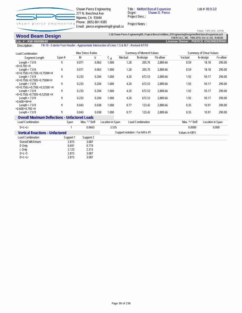
Description : FB-10 - Exterior Foor Header - Approxmiate Intersection of Lines 1.5 & M.7 - Revised 4/7/10
Shawn Pierce Engineering277 N. Beechnut AveNipomo, CA 93444Phone: (805) 801-9385Email: [email protected]
Title : Melford Borzall Expansion Job # 09.9-2/2
Project Desc.:Dsgnr: Shawn D. Pierce
Project Notes :
Material Properties
Beam Bracing :
Calculations per IBC 2006, CBC 2007, 2005 NDS
Completely Unbraced
Allowable Stress Design
iLevel Truss JoistParallam PSL 2.0E
2,900.02,900.02,900.0
750.0
2,000.02,000.0
290.02,025.0 32.210
Analysis Method :
Eminbend - xx ksiWood Species :Wood Grade :
Fb - Tensionpsipsi
Fv psi
Fb - Compr
Ft psi
Fc - Prll psipsiFc - Perp
E : Modulus of ElasticityEbend- xx ksi
Density pcf
Load Combination :2006 IBC & ASCE 7-05
5.25x9.25
Span = 7.0 ft
D(0.119,0.154) L(0.425,0.55)D(0.044,0.08)
L(0.1275,0.165)
.Applied Loads Service loads entered. Load Factors will be applied for calculations.
Beam self weight calculated and added to loadsLoad for Span Number 1
Varying Uniform Load : D(S,E) = 0.1190->0.1540, L(S,E) = 0.4250->0.550 k/ft, Extent = 0.0 -->> 7.0 ft, Trib Width = 1.0 ftVarying Uniform Load : D(S,E) = 0.0440->0.080 k/ft, Extent = 0.0 -->> 7.0 ft, Trib Width = 1.0 ftVarying Uniform Load : L(S,E) = 0.1275->0.1650 k/ft, Extent = 0.0 -->> 7.0 ft, Trib Width = 1.0 ft, (Partition Load)
.DESIGN SUMMARY Design OKMaximum Bending Stress Ratio 0.287: 1
Load Combination +D+L+H
Span # where maximum occurs Span # 1Location of maximum on span 3.570ft
72.83 psi=
=
FB : Allowable 2,889.66psi Fv : Allowable
5.25x9.25Section used for this span
Span # where maximum occursLocation of maximum on span
Span # 1=
Load Combination +D+L+H=
=
=
290.00 psi==
Section used for this span 5.25x9.25fb : Actual
Maximum Shear Stress Ratio 0.251 : 1
6.230 ft==
828.15psi fv : Actual
Maximum Deflection
0 <4801267
Ratio = 0 <360
Max Downward L+Lr+S Deflection 0.050 in 1685Ratio =Max Upward L+Lr+S Deflection 0.000 in Ratio =Max Downward Total Deflection 0.066 in Ratio =Max Upward Total Deflection 0.000 in
.Maximum Forces & Stresses for Load Combinations
Span #Summary of Moment ValuesLoad Combination
d
Summary of Shear ValuesMax Stress RatiosM CV fb-designMactual fv-designFb-allow Vactual Fv-allowSegment Length
+D Length = 7.0 ft 1 0.071 0.063 1.000 1.28 205.70 2,889.66 0.59 290.00 18.18+D+L+H Length = 7.0 ft 1 0.287 0.251 1.000 5.17 828.15 2,889.66 2.36 290.00 72.83+D+Lr+H Length = 7.0 ft 1 0.071 0.063 1.000 1.28 205.70 2,889.66 0.59 290.00 18.18+D+S+H Length = 7.0 ft 1 0.071 0.063 1.000 1.28 205.70 2,889.66 0.59 290.00 18.18+D+0.750Lr+0.750L+H Length = 7.0 ft 1 0.233 0.204 1.000 4.20 672.53 2,889.66 1.92 290.00 59.17+D+0.750L+0.750S+H Length = 7.0 ft 1 0.233 0.204 1.000 4.20 672.53 2,889.66 1.92 290.00 59.17+D+W+H
Page 37 of 236
Wood Beam Design ENERCALC, INC. 1983-2010, Ver: 6.1.03, N:40336License Owner : PIERCE ENGINEERINGLic. # : KW-06008640
File: Z:\@Shawn Pierce Engineering\09_Projects\Borzal Addition_02\Engineering\Design\melford borzall expansion.ec6Printed: 7 APR 2010, 2:41PM
Description : FB-10 - Exterior Foor Header - Approxmiate Intersection of Lines 1.5 & M.7 - Revised 4/7/10
Shawn Pierce Engineering277 N. Beechnut AveNipomo, CA 93444Phone: (805) 801-9385Email: [email protected]
Title : Melford Borzall Expansion Job # 09.9-2/2
Project Desc.:Dsgnr: Shawn D. Pierce
Project Notes :
Span #Summary of Moment ValuesLoad Combination
d
Summary of Shear ValuesMax Stress RatiosM CV fb-designMactual fv-designFb-allow Vactual Fv-allowSegment Length
Length = 7.0 ft 1 0.071 0.063 1.000 1.28 205.70 2,889.66 0.59 290.00 18.18+D+0.70E+H Length = 7.0 ft 1 0.071 0.063 1.000 1.28 205.70 2,889.66 0.59 290.00 18.18+D+0.750Lr+0.750L+0.750W+H Length = 7.0 ft 1 0.233 0.204 1.000 4.20 672.53 2,889.66 1.92 290.00 59.17+D+0.750L+0.750S+0.750W+H Length = 7.0 ft 1 0.233 0.204 1.000 4.20 672.53 2,889.66 1.92 290.00 59.17+D+0.750Lr+0.750L+0.5250E+H Length = 7.0 ft 1 0.233 0.204 1.000 4.20 672.53 2,889.66 1.92 290.00 59.17+D+0.750L+0.750S+0.5250E+H Length = 7.0 ft 1 0.233 0.204 1.000 4.20 672.53 2,889.66 1.92 290.00 59.17+0.60D+W+H Length = 7.0 ft 1 0.043 0.038 1.000 0.77 123.42 2,889.66 0.35 290.00 10.91+0.60D+0.70E+H Length = 7.0 ft 1 0.043 0.038 1.000 0.77 123.42 2,889.66 0.35 290.00 10.91
.Location in SpanLoad CombinationMax. "-" Defl Location in SpanLoad Combination Span Max. "+" Defl
Overall Maximum Deflections - Unfactored Loads
D+L+Lr 1 0.0663 3.535 0.0000 0.000.
Load Combination Support 1 Support 2Vertical Reactions - Unfactored Support notation : Far left is #1 Values in KIPS
Overall MAXimum 2.815 3.087D Only 0.691 0.774L Only 2.123 2.313D+L+S 2.815 3.087D+L+Lr 2.815 3.087
Page 38 of 236

Wood Beam Design ENERCALC, INC. 1983-2010, Ver: 6.1.03, N:40336License Owner : PIERCE ENGINEERINGLic. # : KW-06008640
File: Z:\@Shawn Pierce Engineering\09_Projects\Borzal Addition_02\Engineering\Design\melford borzall expansion.ec6Printed: 7 APR 2010, 2:44PM
Description : FB-11 - Floor Beam o/ Hallway - Revised 4/7/10
Shawn Pierce Engineering277 N. Beechnut AveNipomo, CA 93444Phone: (805) 801-9385Email: [email protected]
Title : Melford Borzall Expansion Job # 09.9-2/2
Project Desc.:Dsgnr: Shawn D. Pierce
Project Notes :
Material Properties
Beam Bracing :
Calculations per IBC 2006, CBC 2007, 2005 NDS
Completely Unbraced
Allowable Stress Design
Douglas Fir - LarchNo.2
875.0875.0600.0625.0
1,300.0470.0
170.0425.0 32.210
Analysis Method :
Eminbend - xx ksiWood Species :Wood Grade :
Fb - Tensionpsipsi
Fv psi
Fb - Compr
Ft psi
Fc - Prll psipsiFc - Perp
E : Modulus of ElasticityEbend- xx ksi
Density pcf
Load Combination :2006 IBC & ASCE 7-05
6x8
Span = 5.50 ft
D(0.119) L(0.425) L(0.1275)
.Applied Loads Service loads entered. Load Factors will be applied for calculations.
Beam self weight calculated and added to loadsLoad for Span Number 1
Uniform Load : D = 0.0140, L = 0.050 ksf, Tributary Width = 8.50 ftUniform Load : L = 0.0150 ksf, Tributary Width = 8.50 ft, (Partition Load)
.DESIGN SUMMARY Design OKMaximum Bending Stress Ratio 0.685: 1
Load Combination +D+L+H
Span # where maximum occurs Span # 1Location of maximum on span 2.750ft
53.10 psi=
=
FB : Allowable 873.88psi Fv : Allowable
6x8Section used for this span
Span # where maximum occursLocation of maximum on span
Span # 1=
Load Combination +D+L+H=
=
=
170.00 psi==
Section used for this span 6x8fb : Actual
Maximum Shear Stress Ratio 0.312 : 1
0.000 ft==
599.04psi fv : Actual
Maximum Deflection
0 <4801174
Ratio = 0 <360
Max Downward L+Lr+S Deflection 0.046 in 1446Ratio =Max Upward L+Lr+S Deflection 0.000 in Ratio =Max Downward Total Deflection 0.056 in Ratio =Max Upward Total Deflection 0.000 in
.Maximum Forces & Stresses for Load Combinations
Span #Summary of Moment ValuesLoad Combination
d
Summary of Shear ValuesMax Stress RatiosM CV fb-designMactual fv-designFb-allow Vactual Fv-allowSegment Length
+D Length = 5.50 ft 1 0.129 0.059 1.000 0.48 112.84 873.88 0.28 170.00 10.00+D+L+H Length = 5.50 ft 1 0.685 0.312 1.000 2.57 599.04 873.88 1.46 170.00 53.10+D+Lr+H Length = 5.50 ft 1 0.129 0.059 1.000 0.48 112.84 873.88 0.28 170.00 10.00+D+S+H Length = 5.50 ft 1 0.129 0.059 1.000 0.48 112.84 873.88 0.28 170.00 10.00+D+0.750Lr+0.750L+H Length = 5.50 ft 1 0.546 0.249 1.000 2.05 477.49 873.88 1.16 170.00 42.32+D+0.750L+0.750S+H Length = 5.50 ft 1 0.546 0.249 1.000 2.05 477.49 873.88 1.16 170.00 42.32+D+W+H Length = 5.50 ft 1 0.129 0.059 1.000 0.48 112.84 873.88 0.28 170.00 10.00
Page 39 of 236

Wood Beam Design ENERCALC, INC. 1983-2010, Ver: 6.1.03, N:40336License Owner : PIERCE ENGINEERINGLic. # : KW-06008640
File: Z:\@Shawn Pierce Engineering\09_Projects\Borzal Addition_02\Engineering\Design\melford borzall expansion.ec6Printed: 7 APR 2010, 2:44PM
Description : FB-11 - Floor Beam o/ Hallway - Revised 4/7/10
Shawn Pierce Engineering277 N. Beechnut AveNipomo, CA 93444Phone: (805) 801-9385Email: [email protected]
Title : Melford Borzall Expansion Job # 09.9-2/2
Project Desc.:Dsgnr: Shawn D. Pierce
Project Notes :
Span #Summary of Moment ValuesLoad Combination
d
Summary of Shear ValuesMax Stress RatiosM CV fb-designMactual fv-designFb-allow Vactual Fv-allowSegment Length
+D+0.70E+H Length = 5.50 ft 1 0.129 0.059 1.000 0.48 112.84 873.88 0.28 170.00 10.00+D+0.750Lr+0.750L+0.750W+H Length = 5.50 ft 1 0.546 0.249 1.000 2.05 477.49 873.88 1.16 170.00 42.32+D+0.750L+0.750S+0.750W+H Length = 5.50 ft 1 0.546 0.249 1.000 2.05 477.49 873.88 1.16 170.00 42.32+D+0.750Lr+0.750L+0.5250E+H Length = 5.50 ft 1 0.546 0.249 1.000 2.05 477.49 873.88 1.16 170.00 42.32+D+0.750L+0.750S+0.5250E+H Length = 5.50 ft 1 0.546 0.249 1.000 2.05 477.49 873.88 1.16 170.00 42.32+0.60D+W+H Length = 5.50 ft 1 0.077 0.035 1.000 0.29 67.70 873.88 0.17 170.00 6.00+0.60D+0.70E+H Length = 5.50 ft 1 0.077 0.035 1.000 0.29 67.70 873.88 0.17 170.00 6.00
.Location in SpanLoad CombinationMax. "-" Defl Location in SpanLoad Combination Span Max. "+" Defl
Overall Maximum Deflections - Unfactored Loads
D+L+Lr 1 0.0562 2.778 0.0000 0.000.
Load Combination Support 1 Support 2Vertical Reactions - Unfactored Support notation : Far left is #1 Values in KIPS
Overall MAXimum 1.872 1.872D Only 0.353 0.353L Only 1.519 1.519D+L+S 1.872 1.872D+L+Lr 1.872 1.872
Page 40 of 236

FRAMING ANALYSIS
Conference Room Expansion
Page 41 of 236

Page 42 of 236
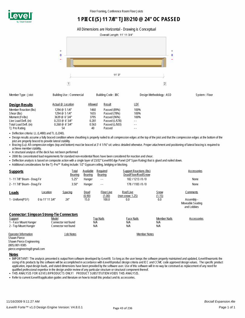
Floor Framing, Conference Room Floor Joists
1 PIECE(S) 11 7/8" TJI® 210 @ 24" OC PASSED
Borzall Expansion.4te
iLevel® Forte™ v1.0 Design Engine Version: V4.8.0.1
11/16/2009 9:11:27 AM
Page 1 of 1
(805) [email protected]
Shawn PierceShawn Pierce Engineering
• 2000 lbs concentrated load requirements for standard non-residential floors have been considered for reaction and shear.• Deflection analysis is based on composite action with a single layer of 23/32" iLevel® Edge Panel (24" Span Rating) that is glued and nailed down.• Additional considerations for the TJ-Pro™ Rating include: 1/2" Gypsum ceiling, bridging or blocking.
• A structural analysis of the deck has not been performed.
• Deflection criteria: LL (L/480) and TL (L/240).• Design results assume a fully braced condition where sheathing is properly nailed to all compression edges at the top of the joist and that the compression edges at the bottom of the
joist are properly braced to provide lateral stability.• Bracing (Lu): All compression edges (top and bottom) must be braced at 3' 4 1/16" o/c unless detailed otherwise. Proper attachment and positioning of lateral bracing is required to
achieve member stability.
• Refer to current iLevel® application guides and literature on how to install this product and its accessories.• THIS ANALYSIS FOR iLEVEL® PRODUCTS ONLY! PRODUCT SUBSTITUTION VOIDS THIS ANALYSIS.
• IMPORTANT! The analysis presented is output from software developed by iLevel®. So long as the user keeps the software properly maintained and updated, iLevel® warrants the sizing of its products by this software will be accomplished in accordance with iLevel® product design criteria and ICC and CCMC code approved design values. The specific product application, input design loads, and stated dimensions have been provided by the software user. Use of this software will in no way be construed as replacement of any need for qualified professional expertise in the design and/or review of any particular structure or structural component thereof.
Notes
TJ Pro Rating 54 40 Passed - -
Live Load Defl. (in) 0.233 @ 6' 3/4" 0.281 Passed (L/578) - -Total Load Defl. (in) 0.268 @ 6' 3/4" 0.563 Passed (L/503) - -
Moment (Ft-lbs) 3639 @ 6' 3/4" 3795 Passed (96%) 100%
Member Reaction (lbs) 1294 @ 5 1/4" 1460 Passed (89%) 100%Shear (lbs) 1294 @ 5 1/4" 1655 Passed (78%) 100%
Design Results Actual @ Location Allowed Result LDF
2 - 11 7/8" Beam - Doug Fir 3.50" Hanger - - 178 / 1183 / 0 / 0 None1 - 11 7/8" Beam - Doug Fir 5.25" Hanger - - 182 / 1213 / 0 / 0 None
Supports TotalBearing
AvailableBearing
RequiredBearing
Support Reactions (lbs)Dead/Floor/Roof/Snow
Accessories
1 - Uniform(PSF) 0 to 11' 11 3/4" 24'' 15.0 100.0 0.0 0.0 Assembly - Moveable Seating
and Lobbies
Loads Location Spacing Dead(0.90)
Floor Live(1.00)
Roof Live(non snow: 1.25)
Snow(1.15)
Comments
Member Type : Joist Building Use : Commercial Building Code : IBC Design Methodology : ASD System : Floor
2 - Top Mount Hanger Connector not found N/A N/A N/A1 - Face Mount Hanger Connector not found N/A N/A N/ASupport Model Top Nails Face Nails Member Nails AccessoriesConnector: Simpson Strong-Tie Connectors
Operator Information Job Notes Member Notes
All Dimensions are Horizontal - Drawing is Conceptual
Page 43 of 236

Floor Framing, Floor Beam - Lines F.5 & J.5
1 PIECE(S) 5 1/4" x 11 7/8" 2.0E Parallam® PSL PASSED
Borzall Expansion.4te
iLevel® Forte™ v1.0 Design Engine Version: V4.8.0.1
11/16/2009 9:12:47 AM
Page 1 of 1
(805) [email protected]
Shawn PierceShawn Pierce Engineering
• Bracing (Lu): All compression edges (top and bottom) must be braced at 19' 4 1/8" o/c unless detailed otherwise. Proper attachment and positioning of lateral bracing is required to achieve member stability.
• 2000 lbs concentrated load requirements for standard non-residential floors have been considered for reaction and shear.
• Deflection criteria: LL (L/480) and TL (L/240).• Design results assume a fully braced condition where all compression edges (top and bottom) are properly braced to provide lateral stability.
• Rim board and squash blocks are NOT designed by this software and loads on these accessories are assumed to bypass the member being designed. Loads at the end of an overhang, even if located on the closure material, are used to design the member.
• Refer to current iLevel® application guides and literature on how to install this product and its accessories.
• IMPORTANT! The analysis presented is output from software developed by iLevel®. So long as the user keeps the software properly maintained and updated, iLevel® warrants the sizing of its products by this software will be accomplished in accordance with iLevel® product design criteria and ICC and CCMC code approved design values. The specific product application, input design loads, and stated dimensions have been provided by the software user. Use of this software will in no way be construed as replacement of any need for qualified professional expertise in the design and/or review of any particular structure or structural component thereof.
• THIS ANALYSIS FOR iLEVEL® PRODUCTS ONLY! PRODUCT SUBSTITUTION VOIDS THIS ANALYSIS.
Notes
Moment (Ft-lbs) 11054 @ 5' 5 3/4" 29854 Passed (37%) 100%Live Load Defl. (in) 0.125 @ 5' 5 3/4" 0.266 Passed (L/999+) - -Total Load Defl. (in) 0.174 @ 5' 5 3/4" 0.531 Passed (L/734) - -
Shear (lbs) 3386 @ 9' 9 5/8" 12053 Passed (28%) 100%Member Reaction (lbs) 4178 @ 2" 5742 Passed (73%) - -Design Results Actual @ Location Allowed Result LDF
2 - 11 7/8" Beam - Doug Fir 3.50" Hanger Hanger 1232 / 3152 / 0 / 0 None1 - Beam - Doug Fir 3.50" 1.75" 1.50" 1207 / 3082 / 0 / 0 1 3/4" Rim Board
Supports TotalBearing
AvailableBearing
RequiredBearing
Support Reactions (lbs)Dead/Floor/Roof/Snow
Accessories
2 - Uniform(PLF) 0 to 11' 1" N/A 117.0 0.0 0.0 0.0
1 - Uniform(PSF) 0 to 11' 1" 5' 7 1/2" 15.0 100.0 0.0 0.0 Assembly - Moveable Seating
and Lobbies
Loads Location Tributary Width Dead(0.90)
Floor Live(1.00)
Roof Live(non snow: 1.25)
Snow(1.15)
Comments
Member Type : Flush Beam Building Use : Commercial Building Code : IBC Design Methodology : ASD System : Floor
2 - Top Mount Hanger Connector not found N/A N/A N/ASupport Model Top Nails Face Nails Member Nails AccessoriesConnector: Simpson Strong-Tie Connectors
Operator Information Job Notes Member Notes
All Dimensions are Horizontal - Drawing is Conceptual
Page 44 of 236
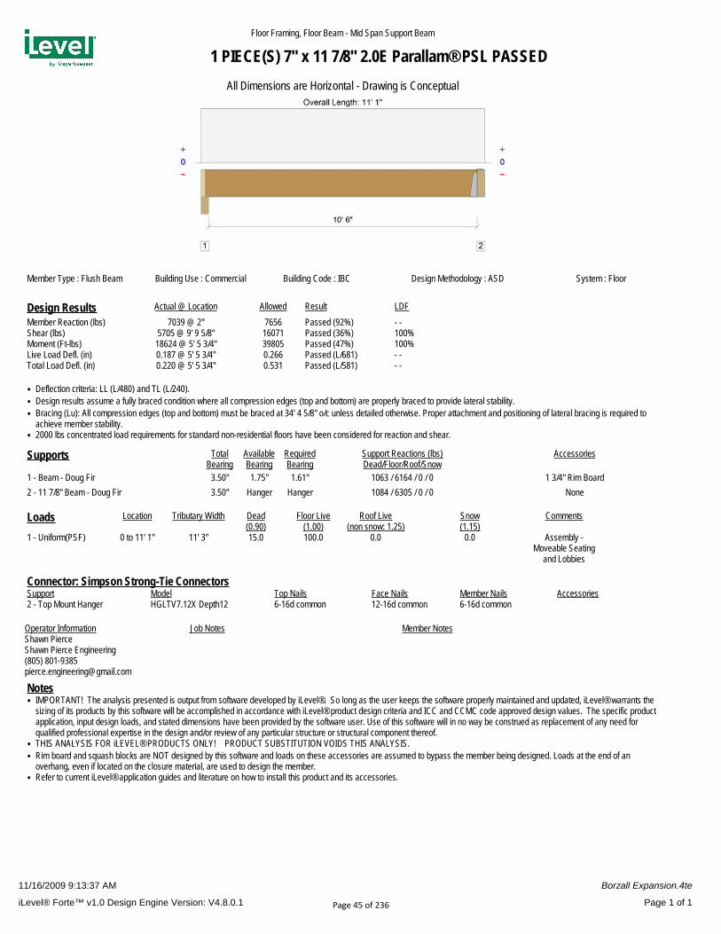
Floor Framing, Floor Beam - Mid Span Support Beam
1 PIECE(S) 7" x 11 7/8" 2.0E Parallam® PSL PASSED
Borzall Expansion.4te
iLevel® Forte™ v1.0 Design Engine Version: V4.8.0.1
11/16/2009 9:13:37 AM
Page 1 of 1
(805) [email protected]
Shawn PierceShawn Pierce Engineering
• Bracing (Lu): All compression edges (top and bottom) must be braced at 34' 4 5/8" o/c unless detailed otherwise. Proper attachment and positioning of lateral bracing is required to achieve member stability.
• 2000 lbs concentrated load requirements for standard non-residential floors have been considered for reaction and shear.
• Deflection criteria: LL (L/480) and TL (L/240).• Design results assume a fully braced condition where all compression edges (top and bottom) are properly braced to provide lateral stability.
• Rim board and squash blocks are NOT designed by this software and loads on these accessories are assumed to bypass the member being designed. Loads at the end of an overhang, even if located on the closure material, are used to design the member.
• Refer to current iLevel® application guides and literature on how to install this product and its accessories.
• IMPORTANT! The analysis presented is output from software developed by iLevel®. So long as the user keeps the software properly maintained and updated, iLevel® warrants the sizing of its products by this software will be accomplished in accordance with iLevel® product design criteria and ICC and CCMC code approved design values. The specific product application, input design loads, and stated dimensions have been provided by the software user. Use of this software will in no way be construed as replacement of any need for qualified professional expertise in the design and/or review of any particular structure or structural component thereof.
• THIS ANALYSIS FOR iLEVEL® PRODUCTS ONLY! PRODUCT SUBSTITUTION VOIDS THIS ANALYSIS.
Notes
Moment (Ft-lbs) 18624 @ 5' 5 3/4" 39805 Passed (47%) 100%Live Load Defl. (in) 0.187 @ 5' 5 3/4" 0.266 Passed (L/681) - -Total Load Defl. (in) 0.220 @ 5' 5 3/4" 0.531 Passed (L/581) - -
Shear (lbs) 5705 @ 9' 9 5/8" 16071 Passed (36%) 100%Member Reaction (lbs) 7039 @ 2" 7656 Passed (92%) - -Design Results Actual @ Location Allowed Result LDF
2 - 11 7/8" Beam - Doug Fir 3.50" Hanger Hanger 1084 / 6305 / 0 / 0 None1 - Beam - Doug Fir 3.50" 1.75" 1.61" 1063 / 6164 / 0 / 0 1 3/4" Rim Board
Supports TotalBearing
AvailableBearing
RequiredBearing
Support Reactions (lbs)Dead/Floor/Roof/Snow
Accessories
1 - Uniform(PSF) 0 to 11' 1" 11' 3" 15.0 100.0 0.0 0.0 Assembly - Moveable Seating
and Lobbies
Loads Location Tributary Width Dead(0.90)
Floor Live(1.00)
Roof Live(non snow: 1.25)
Snow(1.15)
Comments
Member Type : Flush Beam Building Use : Commercial Building Code : IBC Design Methodology : ASD System : Floor
2 - Top Mount Hanger HGLTV7.12X Depth12 6-16d common 12-16d common 6-16d commonSupport Model Top Nails Face Nails Member Nails AccessoriesConnector: Simpson Strong-Tie Connectors
Operator Information Job Notes Member Notes
All Dimensions are Horizontal - Drawing is Conceptual
Page 45 of 236
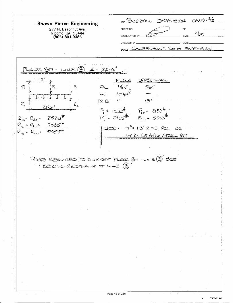
Page 46 of 236

Floor Framing, Floor beam - Line 3
1 PIECE(S) 7" x 18" 2.0E Parallam® PSL PASSED
Borzall Expansion.4te
iLevel® Forte™ v1.0 Design Engine Version: V4.8.0.1
11/16/2009 9:14:12 AM
Page 1 of 1
(805) [email protected]
Shawn PierceShawn Pierce Engineering
• Bracing (Lu): All compression edges (top and bottom) must be braced at 23' 5" o/c unless detailed otherwise. Proper attachment and positioning of lateral bracing is required to achieve member stability.
• 2000 lbs concentrated load requirements for standard non-residential floors have been considered for reaction and shear.
• Deflection criteria: LL (L/480) and TL (L/240).• Design results assume a fully braced condition where all compression edges (top and bottom) are properly braced to provide lateral stability.
• Refer to current iLevel® application guides and literature on how to install this product and its accessories.• THIS ANALYSIS FOR iLEVEL® PRODUCTS ONLY! PRODUCT SUBSTITUTION VOIDS THIS ANALYSIS.
• IMPORTANT! The analysis presented is output from software developed by iLevel®. So long as the user keeps the software properly maintained and updated, iLevel® warrants the sizing of its products by this software will be accomplished in accordance with iLevel® product design criteria and ICC and CCMC code approved design values. The specific product application, input design loads, and stated dimensions have been provided by the software user. Use of this software will in no way be construed as replacement of any need for qualified professional expertise in the design and/or review of any particular structure or structural component thereof.
Notes
Moment (Ft-lbs) 49363 @ 11' 3" 87330 Passed (57%) 100%Live Load Defl. (in) 0.507 @ 11' 3" 0.569 Passed (L/539) - -Total Load Defl. (in) 0.619 @ 11' 3" 1.138 Passed (L/441) - -
Shear (lbs) 5856 @ 21' 5 1/2" 24360 Passed (24%) 100%Member Reaction (lbs) 9401 @ 4" 28875 Passed (33%) - -Design Results Actual @ Location Allowed Result LDF
2 - Column - Doug Fir 5.50" 5.50" 1.70" 2039 / 6886 / 0 / 0 None1 - Column - Doug Fir 5.50" 5.50" 1.79" 2126 / 7276 / 0 / 0 None
Supports TotalBearing
AvailableBearing
RequiredBearing
Support Reactions (lbs)Dead/Floor/Roof/Snow
Accessories
4 - Point(lb) 22' 6" N/A 1030 2955 0 0 Beam on F.53 - Point(lb) 11' 3" N/A 830 5910 0 0 Beam at Midspan2 - Point(lb) 0 N/A 1030 2955 0 0 Beam on J.5
1 - Uniform(PSF) 0 to 23' 5" 1' 15.0 100.0 0.0 0.0 Assembly - Moveable Seating
and Lobbies
Loads Location Tributary Width Dead(0.90)
Floor Live(1.00)
Roof Live(non snow: 1.25)
Snow(1.15)
Comments
Member Type : Flush Beam Building Use : Commercial Building Code : IBC Design Methodology : ASD System : Floor
Operator Information Job Notes Member Notes
All Dimensions are Horizontal - Drawing is Conceptual
Page 47 of 236

FOUNDATION ANALYSIS
Page 48 of 236

Foundation Analysis
General Soil Information used for design of Foundation in this section:
1. Minimum required soil bearing pressure for DL + LL = 2000 psf. 2. Minimum footing requirements for stud walls shall be per Table
1805.4.2 of 2007 California Building Code, unless a soils investigation requires, or these structural calculations, requires otherwise.
3. This firm recommends that on building sites exhibiting characteristics of instability, a soils investigation be prepared, unless waived by the local building review agency. Deviation from design values used in these calculations shall be brought to this firms attention immediately.
4. Soils Report prepared by:
GSI Soils, Inc.
141 Suburban Road - Suite D-1
San Luis Obispo, CA
Report No.: 98-138 Date: 11/23/09
Page 49 of 236

FOUNDATION ANALYSIS
Metal Building Foundation
Page 50 of 236

Page 51 of 236
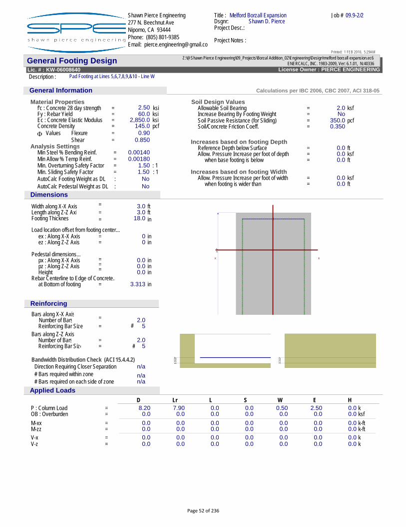
General Footing Design ENERCALC, INC. 1983-2009, Ver: 6.1.01, N:40336License Owner : PIERCE ENGINEERINGLic. # : KW-06008640
File: Z:\@Shawn Pierce Engineering\09_Projects\Borzal Addition_02\Engineering\Design\melford borzall expansion.ec6Printed: 1 FEB 2010, 5:29AM
Description : Pad Footing at Lines 5,6,7,8,9,&10 - Line W
Shawn Pierce Engineering277 N. Beechnut AveNipomo, CA 93444Phone: (805) 801-9385Email: [email protected]
Title : Melford Borzall Expansion Job # 09.9-2/2
Project Desc.:Dsgnr: Shawn D. Pierce
Project Notes :
Calculations per IBC 2006, CBC 2007, ACI 318-05General Information
Material Properties Soil Design Values2.0
Analysis Settings
350.0ksiNo
ksfAllowable Soil Bearing ==
2.5060.0
2,850.0145.0
0.00140
= 0.350Flexure = 0.90Shear =
Values
0.00180
0.0
Soil Passive Resistance (for Sliding)
1.501.50
=
Increases based on footing Width
:AutoCalc Pedestal Weight as DL No
Allow. Pressure Increase per foot of width = 0.0 ksfwhen footing is wider than = 0.0 ft
:
=
AutoCalc Footing Weight as DL No
when base footing is below 0.0 ft
pcf
Increase Bearing By Footing Weight= pcf
Min. Overturning Safety Factor=
: 1
Increases based on footing Depth0.850=
Soil/Concrete Friction Coeff.Ec : Concrete Elastic Modulus
Min. Sliding Safety Factor=
=
: 1
Reference Depth below Surface0.0
ft=Allow. Pressure Increase per foot of depth ksf
=
=
=
Concrete Density
=
Min Allow % Temp Reinf.
ksif'c : Concrete 28 day strengthFy : Rebar Yield ksi
Min Steel % Bending Reinf.
Ed
ge
Dist. =
3"
3'-0"
3'-0
"
Z
Z
X X
2 - # 5 Bars3.31
3"
X-X Section Looking to +Z 2 - # 5 Bars
3.3
13"
Z-Z Section Looking to +X
#
Dimensions
Width along X-X Axis 3.0 ftLength along Z-Z Axis
=3.0 ft
Load location offset from footing center...ex : Along X-X Axis 0 inez : Along Z-Z Axis 0 in
=Pedestal dimensions...
==
px : Along X-X Axis 0.0 inpz : Along Z-Z Axis 0.0 inHeight =
=0.0 in
Footing Thickness=
18.0 in=
Rebar Centerline to Edge of Concrete...= inat Bottom of footing 3.313
Reinforcing
#
Bars along X-X Axis
Reinforcing Bar Size=
5Number of Bars
=2.0
Bars along Z-Z Axis
Reinforcing Bar Size = 5Number of Bars = 2.0
Bandwidth Distribution Check (ACI 15.4.4.2)Direction Requiring Closer Separation n/a# Bars required within zone n/a# Bars required on each side of zone n/a
Applied Loads
8.20 7.90 0.0 0.0 0.50 2.50 0.00.0 0.0 0.0 0.0 0.0 0.0 0.0
D Lr
ksf
L SP : Column LoadOB : Overburden =
kW E
M-zzV-x
== 0.0 k
0.00.0 0.0 0.0 0.0 0.0
V-z 0.0 k0.0 0.0 0.0 0.0 0.00.0
0.0 0.0M-xx =
0.0 k-ft= 0.0 0.00.0 k-ft
0.00.0
0.00.0 0.0 0.0 0.0 0.0
H=
Page 52 of 236

General Footing Design ENERCALC, INC. 1983-2009, Ver: 6.1.01, N:40336License Owner : PIERCE ENGINEERINGLic. # : KW-06008640
File: Z:\@Shawn Pierce Engineering\09_Projects\Borzal Addition_02\Engineering\Design\melford borzall expansion.ec6Printed: 1 FEB 2010, 5:29AM
Description : Pad Footing at Lines 5,6,7,8,9,&10 - Line W
Shawn Pierce Engineering277 N. Beechnut AveNipomo, CA 93444Phone: (805) 801-9385Email: [email protected]
Title : Melford Borzall Expansion Job # 09.9-2/2
Project Desc.:Dsgnr: Shawn D. Pierce
Project Notes :
DESIGN SUMMARY Design OK
Governing Load CombinationMin. Ratio Item Applied CapacityPASS 0.8945 Soil Bearing 1.789 ksf 2.0 ksf +D+Lr+HPASS n/a Overturning - X-X 0.0 k-ft 0.0 k-ft No OverturningPASS n/a Overturning - Z-Z 0.0 k-ft 0.0 k-ft No OverturningPASS n/a Sliding - X-X 0.0 k 0.0 k No SlidingPASS n/a Sliding - Z-Z 0.0 k 0.0 k No SlidingPASS n/a Uplift 0.0 k 0.0 k No UpliftPASS 0.2129 Z Flexure (+X) 2.859 k-ft 13.433 k-ft +1.20D+1.60Lr+0.80WPASS 0.2129 Z Flexure (-X) 2.859 k-ft 13.433 k-ft +1.20D+1.60Lr+0.80WPASS 0.2129 X Flexure (+Z) 2.859 k-ft 13.433 k-ft +1.20D+1.60Lr+0.80WPASS 0.2129 X Flexure (-Z) 2.859 k-ft 13.433 k-ft +1.20D+1.60Lr+0.80WPASS 0.04752 1-way Shear (+X) 4.039 psi 85.0 psi +1.20D+1.60Lr+0.80WPASS 0.04752 1-way Shear (-X) 4.039 psi 85.0 psi +1.20D+1.60Lr+0.80WPASS 0.04752 1-way Shear (+Z) 4.039 psi 85.0 psi +1.20D+1.60Lr+0.80WPASS 0.04752 1-way Shear (-Z) 4.039 psi 85.0 psi +1.20D+1.60Lr+0.80WPASS 0.1293 2-way Punching 21.987 psi 170.0 psi +1.20D+1.60Lr+0.80W
Detailed Results
Rotation Axis &ZeccXecc
Actual Soil Bearing Stress Actual / AllowableSoil Bearing
Gross Allowable +Z +Z -X -X RatioLoad Combination...X-X, +D 2.0 n/a0.9111 0.9111 n/a 0.4560.0n/aX-X, +D+L+H 2.0 n/a0.9111 0.9111 n/a 0.4560.0n/aX-X, +D+Lr+H 2.0 n/a1.789 1.789 n/a 0.8950.0n/aX-X, +D+0.750Lr+0.750L+H 2.0 n/a1.569 1.569 n/a 0.7850.0n/aX-X, +D+W+H 2.0 n/a0.9667 0.9667 n/a 0.4830.0n/aX-X, +D+0.70E+H 2.0 n/a1.106 1.106 n/a 0.5530.0n/aX-X, +D+0.750Lr+0.750L+0.750W+H 2.0 n/a1.611 1.611 n/a 0.8060.0n/aX-X, +D+0.750L+0.750S+0.750W+H 2.0 n/a0.9528 0.9528 n/a 0.4760.0n/aX-X, +D+0.750Lr+0.750L+0.5250E+H 2.0 n/a1.715 1.715 n/a 0.8580.0n/aX-X, +D+0.750L+0.750S+0.5250E+H 2.0 n/a1.057 1.057 n/a 0.5290.0n/aX-X, +0.60D+W+H 2.0 n/a0.6022 0.6022 n/a 0.3010.0n/aX-X, +0.60D+0.70E+H 2.0 n/a0.7411 0.7411 n/a 0.3710.0n/aZ-Z, +D 2.0 0.9111n/a n/a 0.9111 0.456n/a0.0Z-Z, +D+L+H 2.0 0.9111n/a n/a 0.9111 0.456n/a0.0Z-Z, +D+Lr+H 2.0 1.789n/a n/a 1.789 0.895n/a0.0Z-Z, +D+0.750Lr+0.750L+H 2.0 1.569n/a n/a 1.569 0.785n/a0.0Z-Z, +D+W+H 2.0 0.9667n/a n/a 0.9667 0.483n/a0.0Z-Z, +D+0.70E+H 2.0 1.106n/a n/a 1.106 0.553n/a0.0Z-Z, +D+0.750Lr+0.750L+0.750W+H 2.0 1.611n/a n/a 1.611 0.806n/a0.0Z-Z, +D+0.750L+0.750S+0.750W+H 2.0 0.9528n/a n/a 0.9528 0.476n/a0.0Z-Z, +D+0.750Lr+0.750L+0.5250E+H 2.0 1.715n/a n/a 1.715 0.858n/a0.0Z-Z, +D+0.750L+0.750S+0.5250E+H 2.0 1.057n/a n/a 1.057 0.529n/a0.0Z-Z, +0.60D+W+H 2.0 0.6022n/a n/a 0.6022 0.301n/a0.0Z-Z, +0.60D+0.70E+H 2.0 0.7411n/a n/a 0.7411 0.371n/a0.0
Rotation Axis &Overturning Stability
Load Combination... StatusOverturning Moment Resisting Moment Stability RatioFooting Has NO Overturning
Force Application AxisSliding Stability
Load Combination... StatusSliding Force Resisting Force Sliding SafetyRatioFooting Has NO Sliding
Footing FlexureAs Req'd
Footing FlexureTension @ Bot.Which
Actual As StatusMu Side ? or Top ? Gvrn. As Phi*MnLoad Combination...Z-Z, +0.90D+E+1.60H 1.235 k-ft +X Bottom 0.02 in2/ft Bending 0.21 in2/ft 13.433 k-ft OKZ-Z, +0.90D+E+1.60H 1.235 k-ft +X Bottom 0.02 in2/ft Bending 0.21 in2/ft 13.433 k-ft OK
Page 53 of 236

General Footing Design ENERCALC, INC. 1983-2009, Ver: 6.1.01, N:40336License Owner : PIERCE ENGINEERINGLic. # : KW-06008640
File: Z:\@Shawn Pierce Engineering\09_Projects\Borzal Addition_02\Engineering\Design\melford borzall expansion.ec6Printed: 1 FEB 2010, 5:29AM
Description : Pad Footing at Lines 5,6,7,8,9,&10 - Line W
Shawn Pierce Engineering277 N. Beechnut AveNipomo, CA 93444Phone: (805) 801-9385Email: [email protected]
Title : Melford Borzall Expansion Job # 09.9-2/2
Project Desc.:Dsgnr: Shawn D. Pierce
Project Notes :
Z-Z, +0.90D+E+1.60H 1.235 k-ft +X Bottom 0.02 in2/ft Bending 0.21 in2/ft 13.433 k-ft OKZ-Z, +0.90D+E+1.60H 1.235 k-ft +X Bottom 0.02 in2/ft Bending 0.21 in2/ft 13.433 k-ft OK
Page 54 of 236

General Footing Design ENERCALC, INC. 1983-2009, Ver: 6.1.01, N:40336License Owner : PIERCE ENGINEERINGLic. # : KW-06008640
File: Z:\@Shawn Pierce Engineering\09_Projects\Borzal Addition_02\Engineering\Design\melford borzall expansion.ec6Printed: 1 FEB 2010, 5:29AM
Description : Pad Footing at Lines 5,6,7,8,9,&10 - Line W
Shawn Pierce Engineering277 N. Beechnut AveNipomo, CA 93444Phone: (805) 801-9385Email: [email protected]
Title : Melford Borzall Expansion Job # 09.9-2/2
Project Desc.:Dsgnr: Shawn D. Pierce
Project Notes :
Footing FlexureAs Req'd
Footing FlexureTension @ Bot.Which
Actual As StatusMu Side ? or Top ? Gvrn. As Phi*MnLoad Combination...Z-Z, +0.90D+E+1.60H 1.235 k-ft +X Bottom 0.02 in2/ft Bending 0.21 in2/ft 13.433 k-ft OKZ-Z, +0.90D+E+1.60H 1.235 k-ft +X Bottom 0.02 in2/ft Bending 0.21 in2/ft 13.433 k-ft OKZ-Z, +0.90D+E+1.60H 1.235 k-ft +X Bottom 0.02 in2/ft Bending 0.21 in2/ft 13.433 k-ft OKZ-Z, +0.90D+E+1.60H 1.235 k-ft +X Bottom 0.02 in2/ft Bending 0.21 in2/ft 13.433 k-ft OKZ-Z, +0.90D+E+1.60H 1.235 k-ft +X Bottom 0.02 in2/ft Bending 0.21 in2/ft 13.433 k-ft OKZ-Z, +0.90D+E+1.60H 1.235 k-ft +X Bottom 0.02 in2/ft Bending 0.21 in2/ft 13.433 k-ft OKZ-Z, +0.90D+E+1.60H 1.235 k-ft +X Bottom 0.02 in2/ft Bending 0.21 in2/ft 13.433 k-ft OKZ-Z, +0.90D+E+1.60H 1.235 k-ft +X Bottom 0.02 in2/ft Bending 0.21 in2/ft 13.433 k-ft OKZ-Z, +0.90D+E+1.60H 1.235 k-ft +X Bottom 0.02 in2/ft Bending 0.21 in2/ft 13.433 k-ft OKZ-Z, +0.90D+E+1.60H 1.235 k-ft +X Bottom 0.02 in2/ft Bending 0.21 in2/ft 13.433 k-ft OKZ-Z, +0.90D+E+1.60H 1.235 k-ft +X Bottom 0.02 in2/ft Bending 0.21 in2/ft 13.433 k-ft OKZ-Z, +0.90D+E+1.60H 1.235 k-ft +X Bottom 0.02 in2/ft Bending 0.21 in2/ft 13.433 k-ft OKZ-Z, +0.90D+E+1.60H 1.235 k-ft +X Bottom 0.02 in2/ft Bending 0.21 in2/ft 13.433 k-ft OKZ-Z, +0.90D+E+1.60H 1.235 k-ft +X Bottom 0.02 in2/ft Bending 0.21 in2/ft 13.433 k-ft OKZ-Z, +0.90D+E+1.60H 1.235 k-ft +X Bottom 0.02 in2/ft Bending 0.21 in2/ft 13.433 k-ft OKZ-Z, +0.90D+E+1.60H 1.235 k-ft +X Bottom 0.02 in2/ft Bending 0.21 in2/ft 13.433 k-ft OKZ-Z, +0.90D+E+1.60H 1.235 k-ft +X Bottom 0.02 in2/ft Bending 0.21 in2/ft 13.433 k-ft OKZ-Z, +0.90D+E+1.60H 1.235 k-ft +X Bottom 0.02 in2/ft Bending 0.21 in2/ft 13.433 k-ft OKZ-Z, +0.90D+E+1.60H 1.235 k-ft +X Bottom 0.02 in2/ft Bending 0.21 in2/ft 13.433 k-ft OKZ-Z, +0.90D+E+1.60H 1.235 k-ft +X Bottom 0.02 in2/ft Bending 0.21 in2/ft 13.433 k-ft OKZ-Z, +0.90D+E+1.60H 1.235 k-ft +X Bottom 0.02 in2/ft Bending 0.21 in2/ft 13.433 k-ft OKZ-Z, +0.90D+E+1.60H 1.235 k-ft +X Bottom 0.02 in2/ft Bending 0.21 in2/ft 13.433 k-ft OKZ-Z, +0.90D+E+1.60H 1.235 k-ft +X Bottom 0.02 in2/ft Bending 0.21 in2/ft 13.433 k-ft OKZ-Z, +0.90D+E+1.60H 1.235 k-ft +X Bottom 0.02 in2/ft Bending 0.21 in2/ft 13.433 k-ft OKZ-Z, +0.90D+E+1.60H 1.235 k-ft +X Bottom 0.02 in2/ft Bending 0.21 in2/ft 13.433 k-ft OKZ-Z, +0.90D+E+1.60H 1.235 k-ft +X Bottom 0.02 in2/ft Bending 0.21 in2/ft 13.433 k-ft OKZ-Z, +0.90D+E+1.60H 1.235 k-ft +X Bottom 0.02 in2/ft Bending 0.21 in2/ft 13.433 k-ft OKZ-Z, +0.90D+E+1.60H 1.235 k-ft +X Bottom 0.02 in2/ft Bending 0.21 in2/ft 13.433 k-ft OKZ-Z, +0.90D+E+1.60H 1.235 k-ft +X Bottom 0.02 in2/ft Bending 0.21 in2/ft 13.433 k-ft OKZ-Z, +0.90D+E+1.60H 1.235 k-ft +X Bottom 0.02 in2/ft Bending 0.21 in2/ft 13.433 k-ft OKZ-Z, +0.90D+E+1.60H 1.235 k-ft +X Bottom 0.02 in2/ft Bending 0.21 in2/ft 13.433 k-ft OKZ-Z, +0.90D+E+1.60H 1.235 k-ft +X Bottom 0.02 in2/ft Bending 0.21 in2/ft 13.433 k-ft OKZ-Z, +0.90D+E+1.60H 1.235 k-ft +X Bottom 0.02 in2/ft Bending 0.21 in2/ft 13.433 k-ft OKZ-Z, +0.90D+E+1.60H 1.235 k-ft +X Bottom 0.02 in2/ft Bending 0.21 in2/ft 13.433 k-ft OKZ-Z, +0.90D+E+1.60H 1.235 k-ft +X Bottom 0.02 in2/ft Bending 0.21 in2/ft 13.433 k-ft OKZ-Z, +0.90D+E+1.60H 1.235 k-ft +X Bottom 0.02 in2/ft Bending 0.21 in2/ft 13.433 k-ft OKZ-Z, +0.90D+E+1.60H 1.235 k-ft +X Bottom 0.02 in2/ft Bending 0.21 in2/ft 13.433 k-ft OKZ-Z, +0.90D+E+1.60H 1.235 k-ft +X Bottom 0.02 in2/ft Bending 0.21 in2/ft 13.433 k-ft OKOne Way Shear
Vu @ +XLoad Combination... Vu @ -X Vu @ -Z Vu @ +Z Vu:Max Phi*Vn / VuPhi Vn Status+0.90D+E+1.60H 1.744 1.744 1.744 1.744 1.744 85.0 0.02052psipsipsipsipsipsi OK+0.90D+E+1.60H 1.744 1.744 1.744 1.744 1.744 85.0 0.02052psipsipsipsipsipsi OK+0.90D+E+1.60H 1.744 1.744 1.744 1.744 1.744 85.0 0.02052psipsipsipsipsipsi OK+0.90D+E+1.60H 1.744 1.744 1.744 1.744 1.744 85.0 0.02052psipsipsipsipsipsi OK+0.90D+E+1.60H 1.744 1.744 1.744 1.744 1.744 85.0 0.02052psipsipsipsipsipsi OK+0.90D+E+1.60H 1.744 1.744 1.744 1.744 1.744 85.0 0.02052psipsipsipsipsipsi OK+0.90D+E+1.60H 1.744 1.744 1.744 1.744 1.744 85.0 0.02052psipsipsipsipsipsi OK+0.90D+E+1.60H 1.744 1.744 1.744 1.744 1.744 85.0 0.02052psipsipsipsipsipsi OK+0.90D+E+1.60H 1.744 1.744 1.744 1.744 1.744 85.0 0.02052psipsipsipsipsipsi OK+0.90D+E+1.60H 1.744 1.744 1.744 1.744 1.744 85.0 0.02052psipsipsipsipsipsi OK
Vu / Phi*VnPunching Shear
StatusVu Phi*VnLoad Combination...+0.90D+E+1.60H 9.494 170.0 0.05585 OKpsipsi+0.90D+E+1.60H 9.494 170.0 0.05585 OKpsipsi+0.90D+E+1.60H 9.494 170.0 0.05585 OKpsipsi+0.90D+E+1.60H 9.494 170.0 0.05585 OKpsipsi+0.90D+E+1.60H 9.494 170.0 0.05585 OKpsipsi+0.90D+E+1.60H 9.494 170.0 0.05585 OKpsipsi+0.90D+E+1.60H 9.494 170.0 0.05585 OKpsipsi+0.90D+E+1.60H 9.494 170.0 0.05585 OKpsipsi+0.90D+E+1.60H 9.494 170.0 0.05585 OKpsipsi
Page 55 of 236
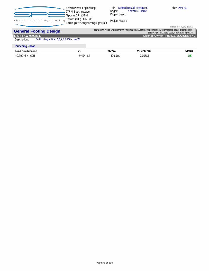
General Footing Design ENERCALC, INC. 1983-2009, Ver: 6.1.01, N:40336License Owner : PIERCE ENGINEERINGLic. # : KW-06008640
File: Z:\@Shawn Pierce Engineering\09_Projects\Borzal Addition_02\Engineering\Design\melford borzall expansion.ec6Printed: 1 FEB 2010, 5:29AM
Description : Pad Footing at Lines 5,6,7,8,9,&10 - Line W
Shawn Pierce Engineering277 N. Beechnut AveNipomo, CA 93444Phone: (805) 801-9385Email: [email protected]
Title : Melford Borzall Expansion Job # 09.9-2/2
Project Desc.:Dsgnr: Shawn D. Pierce
Project Notes :
Vu / Phi*VnPunching Shear
StatusVu Phi*VnLoad Combination...+0.90D+E+1.60H 9.494 170.0 0.05585 OKpsipsi
Page 56 of 236

Anchor Calculations
Anchor Designer for ACI 318 (Version 4.2.0.2)
Job Name : Borzal - Line 5-10 @ W Date/Time : 2/1/2010 5:58:33 AM
1) Input
Calculation Method : ACI 318 Appendix D For Cracked Concrete Calculation Type : Analysis
a) LayoutAnchor : 3/4" Heavy Hex Bolt Number of Anchors : 4Steel Grade: F1554 GR. 36 Embedment Depth : 6 inBuilt-up Grout Pads : No
Anchor Layout Dimensions : cx1 : 16.5 in
cx2 : 16.5 in
cy1 : 11.5 in
cy2 : 21.5 in
bx1 : 2.5 in
bx2 : 2.5 in
by1 : 3.5 in
by2 : 4.5 in
sx1 : 3 in
sy1 : 3 in
Page 1 of 5
2/1/2010about:blank
Page 57 of 236

Warning: Edge distance(s) and/or spacing(s) entered are not in compliance with minimum 6 times the anchor diameter requirements for torqued bolts as detailed in ACI 318 Section D.8.1 and D.8.2. User is responsible for complying with minimum cover requirements in ACI 318.
b) Base Material
Concrete : Normal weight f'c : 2500.0 psi
Cracked Concrete : Yes c,V : 1.00
Condition : A tension and shear Fp : 1381.3 psi
Thickness, h : 18 inSupplementary edge reinforcement : No
c) Factored LoadsLoad factor source : ACI 318 Section 9.2Nua : 9400 lb Vuax : 0 lb
Vuay : -7700 lb Mux : 0 lb*ft
Muy : 0 lb*ft
ex : 0 in
ey : 0 in
Moderate/high seismic risk or intermediate/high design category : NoApply entire shear load at front row for breakout : No d) Anchor Parameters
Anchor Model = HB75 do = 0.75 in
Category = N/A hef = 5.25 in
hmin = 6.75 in cac = 7.875 in
cmin = [minimum required by ACI 318 Section D8.2] smin = 3 in
Ductile = Yes
2) Tension Force on Each Individual Anchor
Anchor #1 Nua1 = 2350.00 lb
Anchor #2 Nua2 = 2350.00 lb
Anchor #3 Nua3 = 2350.00 lb
Anchor #4 Nua4 = 2350.00 lb
Sum of Anchor Tension Nua = 9400.00 lb
ax = 0.00 in
ay = 0.00 in
e'Nx = 0.00 in
Page 2 of 5
2/1/2010about:blank
Page 58 of 236

e'Ny = 0.00 in
3) Shear Force on Each Individual Anchor
Resultant shear forces in each anchor:Anchor #1 Vua1 = 1925.00 lb (Vua1x = 0.00 lb , Vua1y = -1925.00 lb )
Anchor #2 Vua2 = 1925.00 lb (Vua2x = 0.00 lb , Vua2y = -1925.00 lb )
Anchor #3 Vua3 = 1925.00 lb (Vua3x = 0.00 lb , Vua3y = -1925.00 lb )
Anchor #4 Vua4 = 1925.00 lb (Vua4x = 0.00 lb , Vua4y = -1925.00 lb )
Sum of Anchor Shear Vuax = 0.00 lb, Vuay = -7700.00 lb
e'Vx = 0.00 in
e'Vy = 0.00 in
4) Steel Strength of Anchor in Tension [Sec. D.5.1]Nsa = nAsefuta [Eq. D-3]
Number of anchors acting in tension, n = 4Nsa = 19370 lb (for each individual anchor)
= 0.75 [D.4.4]
Nsa = 14527.50 lb (for each individual anchor)
5) Concrete Breakout Strength of Anchor Group in Tension [Sec. D.5.2]
Ncbg = ANc/ANcoec,Ned,Nc,Ncp,NNb [Eq. D-5]
Number of influencing edges = 0hef = 5.25 in
ANco = 248.06 in2 [Eq. D-6]
ANc = 351.56 in2
ec,Nx = 1.0000 [Eq. D-9]
ec,Ny = 1.0000 [Eq. D-9]
ec,N = 1.0000 (Combination of x-axis & y-axis eccentricity factors.)
ed,N = 1.0000 [Eq. D-10 or D-11]
Note: Cracking shall be controlled per D.5.2.6
c,N = 1.0000 [Sec. D.5.2.6]
cp,N = 1.0000 [Eq. D-12 or D-13]
Nb = kc f ' c hef1.5 = 14435.11 lb [Eq. D-7]
kc = 24 [Sec. D.5.2.6]
Ncbg = 20457.93 lb [Eq. D-5]
= 0.75 [D.4.4]
Page 3 of 5
2/1/2010about:blank
Page 59 of 236

Ncbg = 15343.45 lb (for the anchor group)
6) Pullout Strength of Anchor in Tension [Sec. D.5.3] Np = 8Abrgf 'c [Eq. D-15]
Abrg = 0.9110 in2
Npn = c,pNp [Eq. D-14]
c,p = 1.0 [D.5.3.6]
Npn = 18220.00 lb
= 0.70 [D.4.4]
Npn = 12754.00 lb (for each individual anchor)
7) Side Face Blowout of Anchor in Tension [Sec. D.5.4]
Concrete side face blowout strength is only calculated for headed anchors in tension close to an edge, ca1 < 0.4hef. Not applicable in this case.
8) Steel Strength of Anchor in Shear [Sec D.6.1] Vsa = n0.6Asefuta [Eq. D-20]
Vsa = 11625.00 lb (for each individual anchor)
= 0.65 [D.4.4]
Vsa = 7556.25 lb (for each individual anchor)
9) Concrete Breakout Strength of Anchor Group in Shear [Sec D.6.2]
Concrete breakout strength has not been evaluated against applied shear load(s) per user option. Refer to Section D.4.2.1 of ACI 318 for conditions where calculations of the concrete breakout strength may not be required.
10) Concrete Pryout Strength of Anchor Group in Shear [Sec. D.6.3]
Vcpg = kcpNcbg [Eq. D-30]
kcp = 2 [Sec. D.6.3.1]
eNx = 0.00 in (Applied shear load eccentricity relative to anchor group c.g.)
eNy = 0.00 in (Applied shear load eccentricity relative to anchor group c.g.)
ec,Nx = 1.0000 [Eq. D-9] (Calulated using applied shear load eccentricity)
ec,Ny = 1.0000 [Eq. D-9] (Calulated using applied shear load eccentricity)
ec,N' = 1.0000 (Combination of x-axis & y-axis eccentricity factors)
Ncbg = (ANca/ANc)(ec,N'/ec,N)Ncbg
Ncbg = 20457.93 lb (from Section (5) of calculations)
ANc = 351.56 in2 (from Section (5) of calculations)
Page 4 of 5
2/1/2010about:blank
Page 60 of 236

ANca = 351.56 in2 (considering all anchors)
ec,N = 1.0000 (from Section(5) of calculations)
Ncbg = 20457.93 lb (considering all anchors)
Vcpg = 40915.85 lb
= 0.70 [D.4.4]
Vcpg = 28641.10 lb (for the anchor group)
11) Check Demand/Capacity Ratios [Sec. D.7]
Tension - Steel : 0.1618- Breakout : 0.6126- Pullout : 0.1843- Sideface Blowout : N/A
Shear - Steel : 0.2548- Breakout : N/A- Pryout : 0.2688
T.Max(0.61) + V.Max(0.27) = 0.88 <= 1.2 [Sec D.7.3]
Interaction check: PASSUse 3/4" diameter F1554 GR. 36 Heavy Hex Bolt anchor(s) with 6 in. embedment
Page 5 of 5
2/1/2010about:blank
Page 61 of 236

Anchor Calculations
Anchor Designer for ACI 318 (Version 4.2.0.2)
Job Name : Borzal - Line 5-10 @ W - EQ+ Date/Time : 2/1/2010 5:55:11 AM
1) Input
Calculation Method : ACI 318 Appendix D For Cracked Concrete Calculation Type : Analysis
a) LayoutAnchor : 3/4" Heavy Hex Bolt Number of Anchors : 4Steel Grade: F1554 GR. 36 Embedment Depth : 6 inBuilt-up Grout Pads : No
Anchor Layout Dimensions : cx1 : 16.5 in
cx2 : 16.5 in
cy1 : 11.5 in
cy2 : 21.5 in
bx1 : 2.5 in
bx2 : 2.5 in
by1 : 3.5 in
by2 : 4.5 in
sx1 : 3 in
sy1 : 3 in
Page 1 of 5
2/1/2010about:blank
Page 62 of 236

Warning: Edge distance(s) and/or spacing(s) entered are not in compliance with minimum 6 times the anchor diameter requirements for torqued bolts as detailed in ACI 318 Section D.8.1 and D.8.2. User is responsible for complying with minimum cover requirements in ACI 318.
b) Base Material
Concrete : Normal weight f'c : 2500.0 psi
Cracked Concrete : Yes c,V : 1.00
Condition : A tension and shear Fp : 1381.3 psi
Thickness, h : 18 inSupplementary edge reinforcement : No
c) Factored LoadsLoad factor source : ACI 318 Section 9.2Nua : 0 lb Vuax : 0 lb
Vuay : 5400 lb Mux : 0 lb*ft
Muy : 0 lb*ft
ex : 0 in
ey : 0 in
Moderate/high seismic risk or intermediate/high design category : YesApply entire shear load at front row for breakout : No d) Anchor Parameters
Anchor Model = HB75 do = 0.75 in
Category = N/A hef = 5.25 in
hmin = 6.75 in cac = 7.875 in
cmin = [minimum required by ACI 318 Section D8.2] smin = 3 in
Ductile = Yes
2) Tension Force on Each Individual Anchor
Anchor #1 Nua1 = 0.00 lb
Anchor #2 Nua2 = 0.00 lb
Anchor #3 Nua3 = 0.00 lb
Anchor #4 Nua4 = 0.00 lb
Sum of Anchor Tension Nua = 0.00 lb
ax = 0.00 in
ay = 0.00 in
e'Nx = 0.00 in
Page 2 of 5
2/1/2010about:blank
Page 63 of 236

e'Ny = 0.00 in
3) Shear Force on Each Individual Anchor
Resultant shear forces in each anchor:Anchor #1 Vua1 = 1350.00 lb (Vua1x = 0.00 lb , Vua1y = 1350.00 lb )
Anchor #2 Vua2 = 1350.00 lb (Vua2x = 0.00 lb , Vua2y = 1350.00 lb )
Anchor #3 Vua3 = 1350.00 lb (Vua3x = 0.00 lb , Vua3y = 1350.00 lb )
Anchor #4 Vua4 = 1350.00 lb (Vua4x = 0.00 lb , Vua4y = 1350.00 lb )
Sum of Anchor Shear Vuax = 0.00 lb, Vuay = 5400.00 lb
e'Vx = 0.00 in
e'Vy = 0.00 in
4) Steel Strength of Anchor in Tension [Sec. D.5.1]Nsa = nAsefuta [Eq. D-3]
Number of anchors acting in tension, n = 0Nsa = 19370 lb (for each individual anchor)
= 0.75 [D.4.4]
Nsa = 14527.50 lb (for each individual anchor)
5) Concrete Breakout Strength of Anchor Group in Tension [Sec. D.5.2]
Ncbg = ANc/ANcoec,Ned,Nc,Ncp,NNb [Eq. D-5]
Number of influencing edges = 0hef = 5.25 in
ANco = 248.06 in2 [Eq. D-6]
ANc = 351.56 in2
ec,Nx = 1.0000 [Eq. D-9]
ec,Ny = 1.0000 [Eq. D-9]
ec,N = 1.0000 (Combination of x-axis & y-axis eccentricity factors.)
ed,N = 1.0000 [Eq. D-10 or D-11]
Note: Cracking shall be controlled per D.5.2.6
c,N = 1.0000 [Sec. D.5.2.6]
cp,N = 1.0000 [Eq. D-12 or D-13]
Nb = kc f ' c hef1.5 = 14435.11 lb [Eq. D-7]
kc = 24 [Sec. D.5.2.6]
Ncbg = 20457.93 lb [Eq. D-5]
= 0.75 [D.4.4]
Page 3 of 5
2/1/2010about:blank
Page 64 of 236

seis = 0.75
Ncbg = 11507.58 lb (for the anchor group)
6) Pullout Strength of Anchor in Tension [Sec. D.5.3] Np = 8Abrgf 'c [Eq. D-15]
Abrg = 0.9110 in2
Npn = c,pNp [Eq. D-14]
c,p = 1.0 [D.5.3.6]
Npn = 18220.00 lb
= 0.70 [D.4.4]
seis = 0.75
Npn = Neq = 9565.50 lb (for each individual anchor)
7) Side Face Blowout of Anchor in Tension [Sec. D.5.4]
Concrete side face blowout strength is only calculated for headed anchors in tension close to an edge, ca1 < 0.4hef. Not applicable in this case.
8) Steel Strength of Anchor in Shear [Sec D.6.1] Veq = 11625.00 lb (for each individual anchor)
= 0.65 [D.4.4]
Veq = 7556.25 lb (for each individual anchor)
9) Concrete Breakout Strength of Anchor Group in Shear [Sec D.6.2]
Concrete breakout strength has not been evaluated against applied shear load(s) per user option. Refer to Section D.4.2.1 of ACI 318 for conditions where calculations of the concrete breakout strength may not be required.
10) Concrete Pryout Strength of Anchor Group in Shear [Sec. D.6.3]
Vcpg = kcpNcbg [Eq. D-30]
kcp = 2 [Sec. D.6.3.1]
eNx = 0.00 in (Applied shear load eccentricity relative to anchor group c.g.)
eNy = 0.00 in (Applied shear load eccentricity relative to anchor group c.g.)
ec,Nx = 1.0000 [Eq. D-9] (Calulated using applied shear load eccentricity)
ec,Ny = 1.0000 [Eq. D-9] (Calulated using applied shear load eccentricity)
ec,N' = 1.0000 (Combination of x-axis & y-axis eccentricity factors)
Ncbg = (ANca/ANc)(ec,N'/ec,N)Ncbg
Ncbg = 20457.93 lb (from Section (5) of calculations)
Page 4 of 5
2/1/2010about:blank
Page 65 of 236

ANc = 351.56 in2 (from Section (5) of calculations)
ANca = 351.56 in2 (considering all anchors)
ec,N = 1.0000 (from Section(5) of calculations)
Ncbg = 20457.93 lb (considering all anchors)
Vcpg = 40915.85 lb
= 0.70 [D.4.4]
seis = 0.75
Vcpg = 21480.82 lb (for the anchor group)
11) Check Demand/Capacity Ratios [Sec. D.7]
Tension - Steel : 0.0000- Breakout : 0.0000- Pullout : 0.0000- Sideface Blowout : N/A
Shear - Steel : 0.1787- Breakout : N/A- Pryout : 0.2514
T.Max(0) <= 0.2 and V.Max(0.25) <= 1.0 [Sec D.7.2]
Interaction check: PASSUse 3/4" diameter F1554 GR. 36 Heavy Hex Bolt anchor(s) with 6 in. embedment
BRITTLE FAILURE GOVERNS: Governing anchor failure mode is brittle failure. Per 2006 IBC Section 1908.1.16, anchors shall be governed by a ductile steel element in structures assigned to Seismic Design Category C, D, E, or F. Alternatively the minimum design strength of the anchor(s) shall be at least 2.5 times the factored forces or the anchor attachment to the structure shall undergo ductile yielding at a load level less than the design strength of the anchor(s). Designer must exercise own judgement to determine if this design is suitable.
Page 5 of 5
2/1/2010about:blank
Page 66 of 236

Anchor Calculations
Anchor Designer for ACI 318 (Version 4.2.0.2)
Job Name : Borzal - Line 5-10 @ W - EQ- Date/Time : 2/1/2010 5:54:16 AM
Calculation Summary - ACI 318 Appendix D For Cracked Concrete
Anchor
Anchor Steel # of Anchors Embedment Depth (in) Category
3/4" Heavy Hex Bolt F1554 GR. 36 4 6 N/A
Concrete
Concrete Cracked f'c(psi) c,V
Normal weight Yes 2500.0 1.00
Condition Thickness (in) Suppl. Edge Reinforcement
A tension and shear 18 No
Factored Loads
Nua (lb) Vuax (lb) Vuay (lb) Mux (lb*ft) Muy (lb*ft)
0 0 -600 0 0
ex(in) ey(in) Mod/high seismic Apply entire shear @ front row
0 0 Yes No
Individual Anchor Tension Loads
N
ua1
(lb)
N
ua2
(lb)
N
ua3
(lb)
N
ua4
(lb)
0.00 0.00 0.00 0.00
e'Nx(in) e'Ny(in)
0.00 0.00
Individual Anchor Shear Loads
V ua1
(lb)
V ua2
(lb)
V ua3
(lb)
V ua4
(lb)
150.00 150.00 150.00 150.00
e'Vx(in) e'Vy(in)
0.00 0.00
Tension Strengths
Steel ( = 0.75 )
Nsa(lb) Nsa(lb) Nua(lb) N ua /Nsa
19370 14527.50 0.00 0.0000
Concrete Breakout ( = 0.75 , seis = 0.75 )
Ncbg(lb) Ncbg(lb) Nua(lb) Nua /Ncbg
20457.93 11507.58 0.00 0.0000
Page 1 of 2
2/1/2010about:blank
Page 67 of 236
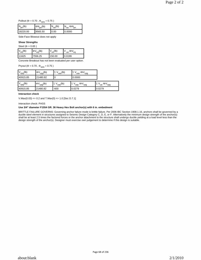
Pullout ( = 0.70 , seis = 0.75 )
Npn(lb) Npn(lb) Nua(lb) Nua /Npn
18220.00 9565.50 0.00 0.0000
Side-Face Blowout does not apply
Shear Strengths
Steel ( = 0.65 )
Veq(lb) Veq(lb) Vua(lb) V ua /Veq
11625 7556.25 150.00 0.0199
Concrete Breakout has not been evaluated per user option.
Pryout ( = 0.70 , seis = 0.75 )
Vcpg(lb) Vcpg(lb) Vuax(lb) Vuax /Vcpg
40915.85 21480.82 0 0.0000
Vcpg(lb) Vcpg(lb) Vuay(lb) Vuay /Vcpg Vua /Vcpg
40915.85 21480.82 -600 0.0279 0.0279
Interaction check
V.Max(0.03) <= 0.2 and T.Max(0) <= 1.0 [Sec D.7.1]
Interaction check: PASS
Use 3/4" diameter F1554 GR. 36 Heavy Hex Bolt anchor(s) with 6 in. embedment
BRITTLE FAILURE GOVERNS: Governing anchor failure mode is brittle failure. Per 2006 IBC Section 1908.1.16, anchors shall be governed by a ductile steel element in structures assigned to Seismic Design Category C, D, E, or F. Alternatively the minimum design strength of the anchor(s) shall be at least 2.5 times the factored forces or the anchor attachment to the structure shall undergo ductile yielding at a load level less than the design strength of the anchor(s). Designer must exercise own judgement to determine if this design is suitable.
Page 2 of 2
2/1/2010about:blank
Page 68 of 236
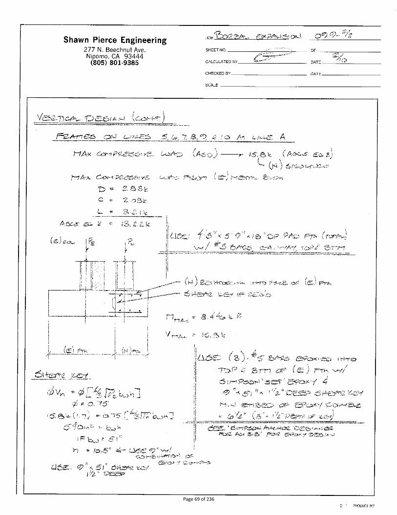
Page 69 of 236

Combined Footing Design ENERCALC, INC. 1983-2009, Ver: 6.1.01, N:40336License Owner : PIERCE ENGINEERINGLic. # : KW-06008640
File: Z:\@Shawn Pierce Engineering\09_Projects\Borzal Addition_02\Engineering\Design\melford borzall expansion.ec6Printed: 1 FEB 2010, 11:23AM
Description : Combining (E) Footing and (N) Footing to resist vertical Loads - Line A
Shawn Pierce Engineering277 N. Beechnut AveNipomo, CA 93444Phone: (805) 801-9385Email: [email protected]
Title : Melford Borzall Expansion Job # 09.9-2/2
Project Desc.:Dsgnr: Shawn D. Pierce
Project Notes :
General InformationMaterial Properties Analysis/Design Settings
YesCalculate footing weight as dead load ?NoCalculate Pedestal weight as dead load ?
2.5060
2,850.0 ksi145
0.00140.0018
1.51.5
pcfMin. Overturning Safety Factor : 1
Ec : Concrete Elastic Modulus
Min. Sliding Safety Factor : 1
Concrete Density Min Allow % Temp Reinf (based on thick)
ksif'c : Concrete 28 day strengthFy : Rebar Yield ksi
Min Steel % Bending Reinf (based on 'd')
0.90.85
: Phi Values Flexure :Shear :
Soil InformationSoil Bearing Increase2
No350.0
0.350
ksf(Allowable Soil Bearing adjusted for footing weight anddepth & width increases as specified by user.)
Increases based on footing Depth . . . .
Increases based on footing Width . . .
Footing base depth below soil surfaceAllowable Soil Bearing ksfIncrease Bearing By Footing Weight
Coefficient of Soil/Concrete Friction
Adjusted Allowable Soil Bearing
Soil Passive Sliding Resistance pcf Allow. Pressure Increase per foot ksfwhen base footing is below ft
Increase per foot of width ksfwhen length -or- width is greater than ft
(Uses entry for "Footing base depth below soil surface" for force)
Maximum Allowed Bearing Pressure 10 ksf(zero is no limit)
ft
Dimensions & Reinforcing
Distance Left of Column #1 ===
2.125 ftBetween Columns 2.083 ftDistance Right of Column #2 1.50 ft
Total Footing Length = 5.708
Col #1
ft
=4.250Footing Width = ft
Pedestal dimensions... Col #2Sq. Dim. 12 12 in=Height in=
in^2
Footing Thickness 18 in in^2
Rebar Center to Concrete Edge @ Top 3 inRebar Center to Concrete Edge @ Bottom 3 in
==
3 53 5
3 53 5
3 53 5
Bottom BarsSize #
As AsCount
0.930 1.652 in^2Req'dActual
1.652 in^2Bars Btwn Cols
Bottom Bars 0.930
0.930 1.652 in^2
Top Bars in^20.930 0.0
Bars Right of Col #2Top Bars 0.930 0.0
Top Bars 0.930 0.0Bottom Bars
Bars left of Col #1
Applied Loads
Applied @ Left ColumnAxial Load DownwardMoment (+CCW) =Shear (+X) =
S E HWLDL Lrk
Applied @ Right Column=
k-ftAxial Load Downward
k-ftk
kMoment (+CCW) =Shear (+X) =
= 4.910 8.310
7.90 7.90
kOverburden =
5'-8-1/2"
2'-1-1/2" 2'-1" 1'-6"
4'-3
"
1'-0
" 1'-0"
3-#5
3-#5
3-#5
3-#5
3-#5
3-#5
1'-6
"
Page 70 of 236

Combined Footing Design ENERCALC, INC. 1983-2009, Ver: 6.1.01, N:40336License Owner : PIERCE ENGINEERINGLic. # : KW-06008640
File: Z:\@Shawn Pierce Engineering\09_Projects\Borzal Addition_02\Engineering\Design\melford borzall expansion.ec6Printed: 1 FEB 2010, 11:23AM
Description : Combining (E) Footing and (N) Footing to resist vertical Loads - Line A
Shawn Pierce Engineering277 N. Beechnut AveNipomo, CA 93444Phone: (805) 801-9385Email: [email protected]
Title : Melford Borzall Expansion Job # 09.9-2/2
Project Desc.:Dsgnr: Shawn D. Pierce
Project Notes :
DESIGN SUMMARY Design OKGoverning Load CombinationRatio Item Applied Capacity
PASS 0.9607 Soil Bearing 1.921 ksf 2.0 ksf D+LrPASS No OTM Overturning 0.0 k-ft 0.0 k-ft No OTMPASS No Sliding Sliding 0.0 k 8.004 k No SlidingPASS No Uplift Uplift 0.0 k 0.0 k No Uplift
PASS No Bending Flexure - Right of Col #2 - Top
Flexure - Left of Col #1 - Top 0.0 k-ft0.05179 Flexure - Left of Col #1 - Bottom 3.195 k-ft
N/APASS
61.698 +1.40DPASS
k-ftFlexure - Between Cols - Top 0.00.0 k-ftNo Bending
+1.20D+1.60Lr+0.50Lk-ft
Flexure - Between Cols - Bottom 8.314 k-ft0.1347 61.698 k-ft0.0 k-ft 0.0 k-ft N/A
PASS 0.1369 Flexure - Right of Col #2 - Bottom 8.446 k-ft 61.698 k-ft +1.20D+1.60Lr+0.50L
PASS 0.08085 1-way Shear - Col #1 6.873 psi 85.0 psi +1.20D+1.60Lr+0.50LPASS 0.05229 1-way Shear - Col #2 4.445 psi 85.0 psi +1.40DPASS 0.03803 2-way Punching - Col #1 6.465 psi 170.0 psi +1.20D+1.60Lr+0.50L
2-way Punching - Col #2 4.896 psi 170.0 psi +1.20D+1.60Lr+0.50LNo Bending N/APASS
PASS0.0 k-ft
PASS 0.02880
Soil BearingEccentricity Actual Soil Bearing Stress Actual / Allow
Total Bearing @ Left Edge @ Right Edgefrom Ftg CL Allowable RatioLoad Combination...+D 18.09 0.44 1.05 2.00 0.526k in ksf ksf ksf 0.394+D+L+H 18.09 0.44 1.05 2.00 0.526k in ksf ksf ksf 0.394+D+Lr+H 34.30 0.91 1.92 2.00 0.961k in ksf ksf ksf 0.343+D+0.750Lr+0.750L+H 30.24 0.79 1.70 2.00 0.852k in ksf ksf ksf 0.350
Moments about Left Edge Moments about Right Edgek-ft k-ftOverturning Stability
Load Combination... Overturning Resisting Ratio Overturning Resisting RatioD 0.00 0.00 999.000 0.00 0.00 999.000D+Lr 0.00 0.00 999.000 0.00 0.00 999.000Sliding Stability
Load Combination... Sliding Force Resisting Force Sliding SafetyRatioD 0.00 8.00 999kkD+Lr 0.00 13.68 999kk
As Req'd
Footing Flexure - Maximum Values for Load CombinationTensionDistance
Actual As Mu / PhiMnbyMu from left SideGoverned
Phi*MnLoad Combination...D+Lr 0.000 0.000 0 0.000 0 0.000 0.000 0.000D+Lr 0.000 0.019 Bottom 1.652 Min. Percent 0.930 61.698 0.000D+Lr 0.001 0.038 Bottom 1.652 Min. Percent 0.930 61.698 0.000D+Lr 0.002 0.057 Bottom 1.652 Min. Percent 0.930 61.698 0.000D+Lr 0.004 0.076 Bottom 1.652 Min. Percent 0.930 61.698 0.000D+Lr 0.006 0.095 Bottom 1.652 Min. Percent 0.930 61.698 0.000D+Lr 0.009 0.114 Bottom 1.652 Min. Percent 0.930 61.698 0.000D+Lr 0.012 0.133 Bottom 1.652 Min. Percent 0.930 61.698 0.000D+Lr 0.016 0.152 Bottom 1.652 Min. Percent 0.930 61.698 0.000D+Lr 0.020 0.171 Bottom 1.652 Min. Percent 0.930 61.698 0.000D+Lr 0.024 0.190 Bottom 1.652 Min. Percent 0.930 61.698 0.000D+Lr 0.030 0.209 Bottom 1.652 Min. Percent 0.930 61.698 0.000D+Lr 0.035 0.228 Bottom 1.652 Min. Percent 0.930 61.698 0.001D+Lr 0.042 0.247 Bottom 1.652 Min. Percent 0.930 61.698 0.001D+Lr 0.048 0.266 Bottom 1.652 Min. Percent 0.930 61.698 0.001D+Lr 0.056 0.285 Bottom 1.652 Min. Percent 0.930 61.698 0.001D+Lr 0.064 0.304 Bottom 1.652 Min. Percent 0.930 61.698 0.001D+Lr 0.072 0.323 Bottom 1.652 Min. Percent 0.930 61.698 0.001D+Lr 0.081 0.342 Bottom 1.652 Min. Percent 0.930 61.698 0.001D+Lr 0.090 0.362 Bottom 1.652 Min. Percent 0.930 61.698 0.001D+Lr 0.101 0.381 Bottom 1.652 Min. Percent 0.930 61.698 0.002D+Lr 0.111 0.400 Bottom 1.652 Min. Percent 0.930 61.698 0.002D+Lr 0.122 0.419 Bottom 1.652 Min. Percent 0.930 61.698 0.002
Page 71 of 236

Combined Footing Design ENERCALC, INC. 1983-2009, Ver: 6.1.01, N:40336License Owner : PIERCE ENGINEERINGLic. # : KW-06008640
File: Z:\@Shawn Pierce Engineering\09_Projects\Borzal Addition_02\Engineering\Design\melford borzall expansion.ec6Printed: 1 FEB 2010, 11:23AM
Description : Combining (E) Footing and (N) Footing to resist vertical Loads - Line A
Shawn Pierce Engineering277 N. Beechnut AveNipomo, CA 93444Phone: (805) 801-9385Email: [email protected]
Title : Melford Borzall Expansion Job # 09.9-2/2
Project Desc.:Dsgnr: Shawn D. Pierce
Project Notes :
As Req'd
Footing Flexure - Maximum Values for Load CombinationTensionDistance
Actual As Mu / PhiMnbyMu from left SideGoverned
Phi*MnLoad Combination...D+Lr 0.134 0.438 Bottom 1.652 Min. Percent 0.930 61.698 0.002D+Lr 0.146 0.457 Bottom 1.652 Min. Percent 0.930 61.698 0.002D+Lr 0.159 0.476 Bottom 1.652 Min. Percent 0.930 61.698 0.003D+Lr 0.173 0.495 Bottom 1.652 Min. Percent 0.930 61.698 0.003D+Lr 0.187 0.514 Bottom 1.652 Min. Percent 0.930 61.698 0.003D+Lr 0.202 0.533 Bottom 1.652 Min. Percent 0.930 61.698 0.003D+Lr 0.217 0.552 Bottom 1.652 Min. Percent 0.930 61.698 0.004D+Lr 0.233 0.571 Bottom 1.652 Min. Percent 0.930 61.698 0.004D+Lr 0.249 0.590 Bottom 1.652 Min. Percent 0.930 61.698 0.004D+Lr 0.266 0.609 Bottom 1.652 Min. Percent 0.930 61.698 0.004D+Lr 0.284 0.628 Bottom 1.652 Min. Percent 0.930 61.698 0.005D+Lr 0.302 0.647 Bottom 1.652 Min. Percent 0.930 61.698 0.005D+Lr 0.321 0.666 Bottom 1.652 Min. Percent 0.930 61.698 0.005D+Lr 0.341 0.685 Bottom 1.652 Min. Percent 0.930 61.698 0.006D+Lr 0.361 0.704 Bottom 1.652 Min. Percent 0.930 61.698 0.006D+Lr 0.382 0.723 Bottom 1.652 Min. Percent 0.930 61.698 0.006D+Lr 0.404 0.742 Bottom 1.652 Min. Percent 0.930 61.698 0.007D+Lr 0.426 0.761 Bottom 1.652 Min. Percent 0.930 61.698 0.007D+Lr 0.449 0.780 Bottom 1.652 Min. Percent 0.930 61.698 0.007D+Lr 0.472 0.799 Bottom 1.652 Min. Percent 0.930 61.698 0.008D+Lr 0.496 0.818 Bottom 1.652 Min. Percent 0.930 61.698 0.008D+Lr 0.521 0.837 Bottom 1.652 Min. Percent 0.930 61.698 0.008D+Lr 0.546 0.856 Bottom 1.652 Min. Percent 0.930 61.698 0.009D+Lr 0.572 0.875 Bottom 1.652 Min. Percent 0.930 61.698 0.009D+Lr 0.599 0.894 Bottom 1.652 Min. Percent 0.930 61.698 0.010D+Lr 0.627 0.913 Bottom 1.652 Min. Percent 0.930 61.698 0.010D+Lr 0.655 0.932 Bottom 1.652 Min. Percent 0.930 61.698 0.011D+Lr 0.684 0.951 Bottom 1.652 Min. Percent 0.930 61.698 0.011D+Lr 0.713 0.970 Bottom 1.652 Min. Percent 0.930 61.698 0.012D+Lr 0.743 0.989 Bottom 1.652 Min. Percent 0.930 61.698 0.012D+Lr 0.774 1.008 Bottom 1.652 Min. Percent 0.930 61.698 0.013D+Lr 0.806 1.027 Bottom 1.652 Min. Percent 0.930 61.698 0.013D+Lr 0.838 1.046 Bottom 1.652 Min. Percent 0.930 61.698 0.014D+Lr 0.872 1.065 Bottom 1.652 Min. Percent 0.930 61.698 0.014D+Lr 0.905 1.085 Bottom 1.652 Min. Percent 0.930 61.698 0.015D+Lr 0.940 1.104 Bottom 1.652 Min. Percent 0.930 61.698 0.015D+Lr 0.975 1.123 Bottom 1.652 Min. Percent 0.930 61.698 0.016D+Lr 1.011 1.142 Bottom 1.652 Min. Percent 0.930 61.698 0.016D+Lr 1.048 1.161 Bottom 1.652 Min. Percent 0.930 61.698 0.017D+Lr 1.085 1.180 Bottom 1.652 Min. Percent 0.930 61.698 0.018D+Lr 1.124 1.199 Bottom 1.652 Min. Percent 0.930 61.698 0.018D+Lr 1.162 1.218 Bottom 1.652 Min. Percent 0.930 61.698 0.019D+Lr 1.202 1.237 Bottom 1.652 Min. Percent 0.930 61.698 0.019D+Lr 1.243 1.256 Bottom 1.652 Min. Percent 0.930 61.698 0.020D+Lr 1.284 1.275 Bottom 1.652 Min. Percent 0.930 61.698 0.021D+Lr 1.326 1.294 Bottom 1.652 Min. Percent 0.930 61.698 0.021D+Lr 1.369 1.313 Bottom 1.652 Min. Percent 0.930 61.698 0.022D+Lr 1.412 1.332 Bottom 1.652 Min. Percent 0.930 61.698 0.023D+Lr 1.457 1.351 Bottom 1.652 Min. Percent 0.930 61.698 0.024D+Lr 1.502 1.370 Bottom 1.652 Min. Percent 0.930 61.698 0.024D+Lr 1.548 1.389 Bottom 1.652 Min. Percent 0.930 61.698 0.025D+Lr 1.595 1.408 Bottom 1.652 Min. Percent 0.930 61.698 0.026D+Lr 1.642 1.427 Bottom 1.652 Min. Percent 0.930 61.698 0.027D+Lr 1.690 1.446 Bottom 1.652 Min. Percent 0.930 61.698 0.027D+Lr 1.740 1.465 Bottom 1.652 Min. Percent 0.930 61.698 0.028D+Lr 1.790 1.484 Bottom 1.652 Min. Percent 0.930 61.698 0.029D+Lr 1.840 1.503 Bottom 1.652 Min. Percent 0.930 61.698 0.030D+Lr 1.892 1.522 Bottom 1.652 Min. Percent 0.930 61.698 0.031D+Lr 1.944 1.541 Bottom 1.652 Min. Percent 0.930 61.698 0.032D+Lr 1.998 1.560 Bottom 1.652 Min. Percent 0.930 61.698 0.032D+Lr 2.052 1.579 Bottom 1.652 Min. Percent 0.930 61.698 0.033D+Lr 2.107 1.598 Bottom 1.652 Min. Percent 0.930 61.698 0.034D+Lr 2.162 1.617 Bottom 1.652 Min. Percent 0.930 61.698 0.035D+Lr 2.219 1.636 Bottom 1.652 Min. Percent 0.930 61.698 0.036
Page 72 of 236

Combined Footing Design ENERCALC, INC. 1983-2009, Ver: 6.1.01, N:40336License Owner : PIERCE ENGINEERINGLic. # : KW-06008640
File: Z:\@Shawn Pierce Engineering\09_Projects\Borzal Addition_02\Engineering\Design\melford borzall expansion.ec6Printed: 1 FEB 2010, 11:23AM
Description : Combining (E) Footing and (N) Footing to resist vertical Loads - Line A
Shawn Pierce Engineering277 N. Beechnut AveNipomo, CA 93444Phone: (805) 801-9385Email: [email protected]
Title : Melford Borzall Expansion Job # 09.9-2/2
Project Desc.:Dsgnr: Shawn D. Pierce
Project Notes :
As Req'd
Footing Flexure - Maximum Values for Load CombinationTensionDistance
Actual As Mu / PhiMnbyMu from left SideGoverned
Phi*MnLoad Combination...D+Lr 2.273 1.655 Bottom 1.652 Min. Percent 0.930 61.698 0.037D+Lr 2.327 1.674 Bottom 1.652 Min. Percent 0.930 61.698 0.038D+Lr 2.378 1.693 Bottom 1.652 Min. Percent 0.930 61.698 0.039D+Lr 2.428 1.712 Bottom 1.652 Min. Percent 0.930 61.698 0.039D+Lr 2.476 1.731 Bottom 1.652 Min. Percent 0.930 61.698 0.040D+Lr 2.523 1.750 Bottom 1.652 Min. Percent 0.930 61.698 0.041D+Lr 2.568 1.769 Bottom 1.652 Min. Percent 0.930 61.698 0.042D+Lr 2.611 1.789 Bottom 1.652 Min. Percent 0.930 61.698 0.042D+Lr 2.653 1.808 Bottom 1.652 Min. Percent 0.930 61.698 0.043D+Lr 2.694 1.827 Bottom 1.652 Min. Percent 0.930 61.698 0.044D+Lr 2.732 1.846 Bottom 1.652 Min. Percent 0.930 61.698 0.044D+Lr 2.769 1.865 Bottom 1.652 Min. Percent 0.930 61.698 0.045D+Lr 2.805 1.884 Bottom 1.652 Min. Percent 0.930 61.698 0.045D+Lr 2.839 1.903 Bottom 1.652 Min. Percent 0.930 61.698 0.046D+Lr 2.871 1.922 Bottom 1.652 Min. Percent 0.930 61.698 0.047D+Lr 2.902 1.941 Bottom 1.652 Min. Percent 0.930 61.698 0.047D+Lr 2.931 1.960 Bottom 1.652 Min. Percent 0.930 61.698 0.048D+Lr 2.959 1.979 Bottom 1.652 Min. Percent 0.930 61.698 0.048D+Lr 2.985 1.998 Bottom 1.652 Min. Percent 0.930 61.698 0.048D+Lr 3.009 2.017 Bottom 1.652 Min. Percent 0.930 61.698 0.049D+Lr 3.033 2.036 Bottom 1.652 Min. Percent 0.930 61.698 0.049D+Lr 3.054 2.055 Bottom 1.652 Min. Percent 0.930 61.698 0.049D+Lr 3.074 2.074 Bottom 1.652 Min. Percent 0.930 61.698 0.050D+Lr 3.092 2.093 Bottom 1.652 Min. Percent 0.930 61.698 0.050D+Lr 3.109 2.112 Bottom 1.652 Min. Percent 0.930 61.698 0.050D+Lr 3.125 2.131 Bottom 1.652 Min. Percent 0.930 61.698 0.051D+Lr 3.138 2.150 Bottom 1.652 Min. Percent 0.930 61.698 0.051D+Lr 3.151 2.169 Bottom 1.652 Min. Percent 0.930 61.698 0.051D+Lr 3.161 2.188 Bottom 1.652 Min. Percent 0.930 61.698 0.051D+Lr 3.171 2.207 Bottom 1.652 Min. Percent 0.930 61.698 0.051D+Lr 3.179 2.226 Bottom 1.652 Min. Percent 0.930 61.698 0.052D+Lr 3.185 2.245 Bottom 1.652 Min. Percent 0.930 61.698 0.052D+Lr 3.190 2.264 Bottom 1.652 Min. Percent 0.930 61.698 0.052D+Lr 3.193 2.283 Bottom 1.652 Min. Percent 0.930 61.698 0.052D+Lr 3.195 2.302 Bottom 1.652 Min. Percent 0.930 61.698 0.052D+Lr 3.195 2.321 Bottom 1.652 Min. Percent 0.930 61.698 0.052D+Lr 3.194 2.340 Bottom 1.652 Min. Percent 0.930 61.698 0.052D+Lr 3.192 2.359 Bottom 1.652 Min. Percent 0.930 61.698 0.052D+Lr 3.187 2.378 Bottom 1.652 Min. Percent 0.930 61.698 0.052D+Lr 3.182 2.397 Bottom 1.652 Min. Percent 0.930 61.698 0.052D+Lr 3.175 2.416 Bottom 1.652 Min. Percent 0.930 61.698 0.051D+Lr 3.167 2.435 Bottom 1.652 Min. Percent 0.930 61.698 0.051D+Lr 3.157 2.454 Bottom 1.652 Min. Percent 0.930 61.698 0.051D+Lr 3.145 2.473 Bottom 1.652 Min. Percent 0.930 61.698 0.051D+Lr 3.133 2.492 Bottom 1.652 Min. Percent 0.930 61.698 0.051D+Lr 3.118 2.512 Bottom 1.652 Min. Percent 0.930 61.698 0.051D+Lr 3.103 2.531 Bottom 1.652 Min. Percent 0.930 61.698 0.050D+Lr 3.086 2.550 Bottom 1.652 Min. Percent 0.930 61.698 0.050D+Lr 3.067 2.569 Bottom 1.652 Min. Percent 0.930 61.698 0.050D+Lr 3.047 2.588 Bottom 1.652 Min. Percent 0.930 61.698 0.049D+Lr 3.026 2.607 Bottom 1.652 Min. Percent 0.930 61.698 0.049D+Lr 8.314 2.626 Bottom 1.652 Min. Percent 0.930 61.698 0.135D+Lr 8.232 2.645 Bottom 1.652 Min. Percent 0.930 61.698 0.133D+Lr 8.153 2.664 Bottom 1.652 Min. Percent 0.930 61.698 0.132D+Lr 8.077 2.683 Bottom 1.652 Min. Percent 0.930 61.698 0.131D+Lr 8.003 2.702 Bottom 1.652 Min. Percent 0.930 61.698 0.130D+Lr 7.931 2.721 Bottom 1.652 Min. Percent 0.930 61.698 0.129D+Lr 7.862 2.740 Bottom 1.652 Min. Percent 0.930 61.698 0.127D+Lr 7.796 2.759 Bottom 1.652 Min. Percent 0.930 61.698 0.126D+Lr 7.733 2.778 Bottom 1.652 Min. Percent 0.930 61.698 0.125D+Lr 7.672 2.797 Bottom 1.652 Min. Percent 0.930 61.698 0.124D+Lr 7.613 2.816 Bottom 1.652 Min. Percent 0.930 61.698 0.123D+Lr 7.557 2.835 Bottom 1.652 Min. Percent 0.930 61.698 0.122D+Lr 7.504 2.854 Bottom 1.652 Min. Percent 0.930 61.698 0.122
Page 73 of 236

Combined Footing Design ENERCALC, INC. 1983-2009, Ver: 6.1.01, N:40336License Owner : PIERCE ENGINEERINGLic. # : KW-06008640
File: Z:\@Shawn Pierce Engineering\09_Projects\Borzal Addition_02\Engineering\Design\melford borzall expansion.ec6Printed: 1 FEB 2010, 11:23AM
Description : Combining (E) Footing and (N) Footing to resist vertical Loads - Line A
Shawn Pierce Engineering277 N. Beechnut AveNipomo, CA 93444Phone: (805) 801-9385Email: [email protected]
Title : Melford Borzall Expansion Job # 09.9-2/2
Project Desc.:Dsgnr: Shawn D. Pierce
Project Notes :
As Req'd
Footing Flexure - Maximum Values for Load CombinationTensionDistance
Actual As Mu / PhiMnbyMu from left SideGoverned
Phi*MnLoad Combination...D+Lr 7.453 2.873 Bottom 1.652 Min. Percent 0.930 61.698 0.121D+Lr 7.405 2.892 Bottom 1.652 Min. Percent 0.930 61.698 0.120D+Lr 7.360 2.911 Bottom 1.652 Min. Percent 0.930 61.698 0.119D+Lr 7.317 2.930 Bottom 1.652 Min. Percent 0.930 61.698 0.119D+Lr 7.277 2.949 Bottom 1.652 Min. Percent 0.930 61.698 0.118D+Lr 7.240 2.968 Bottom 1.652 Min. Percent 0.930 61.698 0.117D+Lr 7.205 2.987 Bottom 1.652 Min. Percent 0.930 61.698 0.117D+Lr 7.173 3.006 Bottom 1.652 Min. Percent 0.930 61.698 0.116D+Lr 7.144 3.025 Bottom 1.652 Min. Percent 0.930 61.698 0.116D+Lr 7.117 3.044 Bottom 1.652 Min. Percent 0.930 61.698 0.115D+Lr 7.093 3.063 Bottom 1.652 Min. Percent 0.930 61.698 0.115D+Lr 7.072 3.082 Bottom 1.652 Min. Percent 0.930 61.698 0.115D+Lr 7.053 3.101 Bottom 1.652 Min. Percent 0.930 61.698 0.114D+Lr 7.037 3.120 Bottom 1.652 Min. Percent 0.930 61.698 0.114D+Lr 7.024 3.139 Bottom 1.652 Min. Percent 0.930 61.698 0.114D+Lr 7.013 3.158 Bottom 1.652 Min. Percent 0.930 61.698 0.114D+Lr 7.006 3.177 Bottom 1.652 Min. Percent 0.930 61.698 0.114D+Lr 7.001 3.196 Bottom 1.652 Min. Percent 0.930 61.698 0.113D+Lr 6.999 3.216 Bottom 1.652 Min. Percent 0.930 61.698 0.113D+Lr 6.999 3.235 Bottom 1.652 Min. Percent 0.930 61.698 0.113D+Lr 7.002 3.254 Bottom 1.652 Min. Percent 0.930 61.698 0.113D+Lr 7.008 3.273 Bottom 1.652 Min. Percent 0.930 61.698 0.114D+Lr 7.017 3.292 Bottom 1.652 Min. Percent 0.930 61.698 0.114D+Lr 7.029 3.311 Bottom 1.652 Min. Percent 0.930 61.698 0.114D+Lr 7.043 3.330 Bottom 1.652 Min. Percent 0.930 61.698 0.114D+Lr 7.060 3.349 Bottom 1.652 Min. Percent 0.930 61.698 0.114D+Lr 7.080 3.368 Bottom 1.652 Min. Percent 0.930 61.698 0.115D+Lr 7.103 3.387 Bottom 1.652 Min. Percent 0.930 61.698 0.115D+Lr 7.129 3.406 Bottom 1.652 Min. Percent 0.930 61.698 0.116D+Lr 7.157 3.425 Bottom 1.652 Min. Percent 0.930 61.698 0.116D+Lr 7.189 3.444 Bottom 1.652 Min. Percent 0.930 61.698 0.117D+Lr 7.223 3.463 Bottom 1.652 Min. Percent 0.930 61.698 0.117D+Lr 7.260 3.482 Bottom 1.652 Min. Percent 0.930 61.698 0.118D+Lr 7.299 3.501 Bottom 1.652 Min. Percent 0.930 61.698 0.118D+Lr 7.342 3.520 Bottom 1.652 Min. Percent 0.930 61.698 0.119D+Lr 7.388 3.539 Bottom 1.652 Min. Percent 0.930 61.698 0.120D+Lr 7.436 3.558 Bottom 1.652 Min. Percent 0.930 61.698 0.121D+Lr 7.487 3.577 Bottom 1.652 Min. Percent 0.930 61.698 0.121D+Lr 7.542 3.596 Bottom 1.652 Min. Percent 0.930 61.698 0.122D+Lr 7.599 3.615 Bottom 1.652 Min. Percent 0.930 61.698 0.123D+Lr 7.659 3.634 Bottom 1.652 Min. Percent 0.930 61.698 0.124D+Lr 7.722 3.653 Bottom 1.652 Min. Percent 0.930 61.698 0.125D+Lr 7.788 3.672 Bottom 1.652 Min. Percent 0.930 61.698 0.126D+Lr 7.856 3.691 Bottom 1.652 Min. Percent 0.930 61.698 0.127D+Lr 7.928 3.710 Bottom 1.652 Min. Percent 0.930 61.698 0.128D+Lr 7.998 3.729 Bottom 1.652 Min. Percent 0.930 61.698 0.130D+Lr 8.062 3.748 Bottom 1.652 Min. Percent 0.930 61.698 0.131D+Lr 8.122 3.767 Bottom 1.652 Min. Percent 0.930 61.698 0.132D+Lr 8.176 3.786 Bottom 1.652 Min. Percent 0.930 61.698 0.133D+Lr 8.226 3.805 Bottom 1.652 Min. Percent 0.930 61.698 0.133D+Lr 8.270 3.824 Bottom 1.652 Min. Percent 0.930 61.698 0.134D+Lr 8.310 3.843 Bottom 1.652 Min. Percent 0.930 61.698 0.135D+Lr 8.344 3.862 Bottom 1.652 Min. Percent 0.930 61.698 0.135D+Lr 8.374 3.881 Bottom 1.652 Min. Percent 0.930 61.698 0.136D+Lr 8.398 3.900 Bottom 1.652 Min. Percent 0.930 61.698 0.136D+Lr 8.417 3.919 Bottom 1.652 Min. Percent 0.930 61.698 0.136D+Lr 8.432 3.939 Bottom 1.652 Min. Percent 0.930 61.698 0.137D+Lr 8.441 3.958 Bottom 1.652 Min. Percent 0.930 61.698 0.137D+Lr 8.446 3.977 Bottom 1.652 Min. Percent 0.930 61.698 0.137D+Lr 8.445 3.996 Bottom 1.652 Min. Percent 0.930 61.698 0.137D+Lr 8.440 4.015 Bottom 1.652 Min. Percent 0.930 61.698 0.137D+Lr 8.429 4.034 Bottom 1.652 Min. Percent 0.930 61.698 0.137D+Lr 8.414 4.053 Bottom 1.652 Min. Percent 0.930 61.698 0.136D+Lr 8.394 4.072 Bottom 1.652 Min. Percent 0.930 61.698 0.136
Page 74 of 236

Combined Footing Design ENERCALC, INC. 1983-2009, Ver: 6.1.01, N:40336License Owner : PIERCE ENGINEERINGLic. # : KW-06008640
File: Z:\@Shawn Pierce Engineering\09_Projects\Borzal Addition_02\Engineering\Design\melford borzall expansion.ec6Printed: 1 FEB 2010, 11:23AM
Description : Combining (E) Footing and (N) Footing to resist vertical Loads - Line A
Shawn Pierce Engineering277 N. Beechnut AveNipomo, CA 93444Phone: (805) 801-9385Email: [email protected]
Title : Melford Borzall Expansion Job # 09.9-2/2
Project Desc.:Dsgnr: Shawn D. Pierce
Project Notes :
As Req'd
Footing Flexure - Maximum Values for Load CombinationTensionDistance
Actual As Mu / PhiMnbyMu from left SideGoverned
Phi*MnLoad Combination...D+Lr 8.368 4.091 Bottom 1.652 Min. Percent 0.930 61.698 0.136D+Lr 8.338 4.110 Bottom 1.652 Min. Percent 0.930 61.698 0.135D+Lr 8.303 4.129 Bottom 1.652 Min. Percent 0.930 61.698 0.135D+Lr 8.263 4.148 Bottom 1.652 Min. Percent 0.930 61.698 0.134D+Lr 8.218 4.167 Bottom 1.652 Min. Percent 0.930 61.698 0.133D+Lr 8.168 4.186 Bottom 1.652 Min. Percent 0.930 61.698 0.132D+Lr 8.114 4.205 Bottom 1.652 Min. Percent 0.930 61.698 0.132D+Lr 8.054 4.224 Bottom 1.652 Min. Percent 0.930 61.698 0.131D+Lr 7.989 4.243 Bottom 1.652 Min. Percent 0.930 61.698 0.129D+Lr 7.920 4.262 Bottom 1.652 Min. Percent 0.930 61.698 0.128D+Lr 7.846 4.281 Bottom 1.652 Min. Percent 0.930 61.698 0.127D+Lr 7.767 4.300 Bottom 1.652 Min. Percent 0.930 61.698 0.126D+Lr 7.683 4.319 Bottom 1.652 Min. Percent 0.930 61.698 0.125D+Lr 7.594 4.338 Bottom 1.652 Min. Percent 0.930 61.698 0.123D+Lr 7.501 4.357 Bottom 1.652 Min. Percent 0.930 61.698 0.122D+Lr 7.402 4.376 Bottom 1.652 Min. Percent 0.930 61.698 0.120D+Lr 7.299 4.395 Bottom 1.652 Min. Percent 0.930 61.698 0.118D+Lr 7.191 4.414 Bottom 1.652 Min. Percent 0.930 61.698 0.117D+Lr 7.078 4.433 Bottom 1.652 Min. Percent 0.930 61.698 0.115D+Lr 6.960 4.452 Bottom 1.652 Min. Percent 0.930 61.698 0.113D+Lr 6.838 4.471 Bottom 1.652 Min. Percent 0.930 61.698 0.111D+Lr 6.711 4.490 Bottom 1.652 Min. Percent 0.930 61.698 0.109D+Lr 6.579 4.509 Bottom 1.652 Min. Percent 0.930 61.698 0.107D+Lr 6.442 4.528 Bottom 1.652 Min. Percent 0.930 61.698 0.104D+Lr 6.300 4.547 Bottom 1.652 Min. Percent 0.930 61.698 0.102D+Lr 6.154 4.566 Bottom 1.652 Min. Percent 0.930 61.698 0.100D+Lr 6.003 4.585 Bottom 1.652 Min. Percent 0.930 61.698 0.097D+Lr 5.847 4.604 Bottom 1.652 Min. Percent 0.930 61.698 0.095D+Lr 5.687 4.623 Bottom 1.652 Min. Percent 0.930 61.698 0.092D+Lr 5.521 4.643 Bottom 1.652 Min. Percent 0.930 61.698 0.089D+Lr 5.351 4.662 Bottom 1.652 Min. Percent 0.930 61.698 0.087D+Lr 5.177 4.681 Bottom 1.652 Min. Percent 0.930 61.698 0.084D+Lr 4.997 4.700 Bottom 1.652 Min. Percent 0.930 61.698 0.081D+Lr 4.815 4.719 Bottom 1.652 Min. Percent 0.930 61.698 0.078D+Lr 4.634 4.738 Bottom 1.652 Min. Percent 0.930 61.698 0.075D+Lr 4.457 4.757 Bottom 1.652 Min. Percent 0.930 61.698 0.072D+Lr 4.284 4.776 Bottom 1.652 Min. Percent 0.930 61.698 0.069D+Lr 4.113 4.795 Bottom 1.652 Min. Percent 0.930 61.698 0.067D+Lr 3.946 4.814 Bottom 1.652 Min. Percent 0.930 61.698 0.064D+Lr 3.783 4.833 Bottom 1.652 Min. Percent 0.930 61.698 0.061D+Lr 3.622 4.852 Bottom 1.652 Min. Percent 0.930 61.698 0.059D+Lr 3.465 4.871 Bottom 1.652 Min. Percent 0.930 61.698 0.056D+Lr 3.312 4.890 Bottom 1.652 Min. Percent 0.930 61.698 0.054D+Lr 3.162 4.909 Bottom 1.652 Min. Percent 0.930 61.698 0.051D+Lr 3.015 4.928 Bottom 1.652 Min. Percent 0.930 61.698 0.049D+Lr 2.872 4.947 Bottom 1.652 Min. Percent 0.930 61.698 0.047D+Lr 2.732 4.966 Bottom 1.652 Min. Percent 0.930 61.698 0.044D+Lr 2.595 4.985 Bottom 1.652 Min. Percent 0.930 61.698 0.042D+Lr 2.462 5.004 Bottom 1.652 Min. Percent 0.930 61.698 0.040D+Lr 2.332 5.023 Bottom 1.652 Min. Percent 0.930 61.698 0.038D+Lr 2.206 5.042 Bottom 1.652 Min. Percent 0.930 61.698 0.036D+Lr 2.083 5.061 Bottom 1.652 Min. Percent 0.930 61.698 0.034D+Lr 1.963 5.080 Bottom 1.652 Min. Percent 0.930 61.698 0.032D+Lr 1.847 5.099 Bottom 1.652 Min. Percent 0.930 61.698 0.030D+Lr 1.735 5.118 Bottom 1.652 Min. Percent 0.930 61.698 0.028D+Lr 1.626 5.137 Bottom 1.652 Min. Percent 0.930 61.698 0.026D+Lr 1.520 5.156 Bottom 1.652 Min. Percent 0.930 61.698 0.025D+Lr 1.418 5.175 Bottom 1.652 Min. Percent 0.930 61.698 0.023D+Lr 1.320 5.194 Bottom 1.652 Min. Percent 0.930 61.698 0.021D+Lr 1.224 5.213 Bottom 1.652 Min. Percent 0.930 61.698 0.020D+Lr 1.133 5.232 Bottom 1.652 Min. Percent 0.930 61.698 0.018D+Lr 1.045 5.251 Bottom 1.652 Min. Percent 0.930 61.698 0.017D+Lr 0.960 5.270 Bottom 1.652 Min. Percent 0.930 61.698 0.016D+Lr 0.879 5.289 Bottom 1.652 Min. Percent 0.930 61.698 0.014
Page 75 of 236

Combined Footing Design ENERCALC, INC. 1983-2009, Ver: 6.1.01, N:40336License Owner : PIERCE ENGINEERINGLic. # : KW-06008640
File: Z:\@Shawn Pierce Engineering\09_Projects\Borzal Addition_02\Engineering\Design\melford borzall expansion.ec6Printed: 1 FEB 2010, 11:23AM
Description : Combining (E) Footing and (N) Footing to resist vertical Loads - Line A
Shawn Pierce Engineering277 N. Beechnut AveNipomo, CA 93444Phone: (805) 801-9385Email: [email protected]
Title : Melford Borzall Expansion Job # 09.9-2/2
Project Desc.:Dsgnr: Shawn D. Pierce
Project Notes :
As Req'd
Footing Flexure - Maximum Values for Load CombinationTensionDistance
Actual As Mu / PhiMnbyMu from left SideGoverned
Phi*MnLoad Combination...D+Lr 0.801 5.308 Bottom 1.652 Min. Percent 0.930 61.698 0.013D+Lr 0.727 5.327 Bottom 1.652 Min. Percent 0.930 61.698 0.012D+Lr 0.657 5.346 Bottom 1.652 Min. Percent 0.930 61.698 0.011D+Lr 0.590 5.366 Bottom 1.652 Min. Percent 0.930 61.698 0.010D+Lr 0.527 5.385 Bottom 1.652 Min. Percent 0.930 61.698 0.009D+Lr 0.467 5.404 Bottom 1.652 Min. Percent 0.930 61.698 0.008D+Lr 0.410 5.423 Bottom 1.652 Min. Percent 0.930 61.698 0.007D+Lr 0.358 5.442 Bottom 1.652 Min. Percent 0.930 61.698 0.006D+Lr 0.309 5.461 Bottom 1.652 Min. Percent 0.930 61.698 0.005D+Lr 0.263 5.480 Bottom 1.652 Min. Percent 0.930 61.698 0.004D+Lr 0.221 5.499 Bottom 1.652 Min. Percent 0.930 61.698 0.004D+Lr 0.183 5.518 Bottom 1.652 Min. Percent 0.930 61.698 0.003D+Lr 0.148 5.537 Bottom 1.652 Min. Percent 0.930 61.698 0.002D+Lr 0.117 5.556 Bottom 1.652 Min. Percent 0.930 61.698 0.002D+Lr 0.090 5.575 Bottom 1.652 Min. Percent 0.930 61.698 0.001D+Lr 0.066 5.594 Bottom 1.652 Min. Percent 0.930 61.698 0.001D+Lr 0.046 5.613 Bottom 1.652 Min. Percent 0.930 61.698 0.001D+Lr 0.029 5.632 Bottom 1.652 Min. Percent 0.930 61.698 0.000D+Lr 0.017 5.651 Bottom 1.652 Min. Percent 0.930 61.698 0.000D+Lr 0.007 5.670 Bottom 1.652 Min. Percent 0.930 61.698 0.000D+Lr 0.002 5.689 Bottom 1.652 Min. Percent 0.930 61.698 0.000D+Lr 0.000 5.708 0 0.000 0 0.000 0.000 0.000One Way Shear Punching Shear
vu @ Col #1Load Combination... Phi Vn vu @ Col #2 vu @ Col #1 vu @ Col #2Phi Vn+1.40D 85.00 3.99 4.44 1.56 0.58 psi 170.00 psi psipsipsipsi+1.20D+0.50Lr+1.60L+1.60H 85.00 4.50 3.72 2.94 1.87 psi 170.00 psi psipsipsipsi+1.20D+1.60Lr+0.50L 85.00 6.87 3.51 6.46 4.90 psi 170.00 psi psipsipsipsi
Page 76 of 236

Anchor Calculations
Anchor Designer for ACI 318 (Version 4.2.0.2)
Job Name : Borzall - Pad Ftg Retrofit Date/Time : 2/1/2010 11:53:29 AM
1) Input
Calculation Method : ACI 318 Appendix D For Cracked Concrete Calculation Type : Analysis
a) LayoutAnchor : 5/8" SET-XP Number of Anchors : 6Steel Grade: A307 GR. C Embedment Depth : 5 inBuilt-up Grout Pads : No
Anchor Layout Dimensions : cx1 : 3.3125 in
cx2 : 3.3125 in
cy1 : 3.3125 in
cy2 : 3.3125 in
bx1 : 1 in
bx2 : 1 in
by1 : 1 in
by2 : 1 in
sx1 : 17.375 in
sy1 : 22.18 in
Page 1 of 10
2/1/2010about:blank
Page 77 of 236

sy2 : 22.128 in
b) Base Material
Concrete : Normal weight f'c : 2500.0 psi
Cracked Concrete : Yes c,V : 1.00
Condition : B tension and shearFp : 1381.3
psiThickness, h : 24 inSupplementary edge reinforcement : NoHole Condition : Dry ConcreteInspection : Continuous
Temperature Range : 1 (Maximum 110 oF short term and 75 oF long term temp.)
c) Factored LoadsLoad factor source : ACI 318 Section 9.2Nua : 0 lb Vuax : 0 lb
Vuay : 0 lb Mux : 0 lb*ft
Muy : 8446 lb*ft
ex : 0 in
ey : 0 in
Moderate/high seismic risk or intermediate/high design category : NoAnchor w/ sustained tension : NoAnchors only resist wind and/or seismic loads : NoApply entire shear load at front row for breakout : No d) Anchor ParametersFrom C-SAS-2009:
Anchor Model = SETXP do = 0.625 in
Category = 1 hef = 5 in
hmin = 8.125 in cac = 15 in
cmin = 1.75 in smin = 3 in
Ductile = Yes
2) Tension Force on Each Individual Anchor
Anchor #1 Nua1 = 1881.00 lb
Anchor #2 Nua2 = 17.27 lb
Anchor #3 Nua3 = 1881.00 lb
Page 2 of 10
2/1/2010about:blank
Page 78 of 236
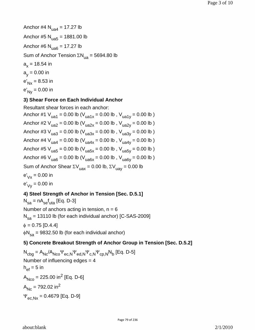
Anchor #4 Nua4 = 17.27 lb
Anchor #5 Nua5 = 1881.00 lb
Anchor #6 Nua6 = 17.27 lb
Sum of Anchor Tension Nua = 5694.80 lb
ax = 18.54 in
ay = 0.00 in
e'Nx = 8.53 in
e'Ny = 0.00 in
3) Shear Force on Each Individual Anchor
Resultant shear forces in each anchor:Anchor #1 Vua1 = 0.00 lb (Vua1x = 0.00 lb , Vua1y = 0.00 lb )
Anchor #2 Vua2 = 0.00 lb (Vua2x = 0.00 lb , Vua2y = 0.00 lb )
Anchor #3 Vua3 = 0.00 lb (Vua3x = 0.00 lb , Vua3y = 0.00 lb )
Anchor #4 Vua4 = 0.00 lb (Vua4x = 0.00 lb , Vua4y = 0.00 lb )
Anchor #5 Vua5 = 0.00 lb (Vua5x = 0.00 lb , Vua5y = 0.00 lb )
Anchor #6 Vua6 = 0.00 lb (Vua6x = 0.00 lb , Vua6y = 0.00 lb )
Sum of Anchor Shear Vuax = 0.00 lb, Vuay = 0.00 lb
e'Vx = 0.00 in
e'Vy = 0.00 in
4) Steel Strength of Anchor in Tension [Sec. D.5.1]Nsa = nAsefuta [Eq. D-3]
Number of anchors acting in tension, n = 6Nsa = 13110 lb (for each individual anchor) [C-SAS-2009]
= 0.75 [D.4.4]
Nsa = 9832.50 lb (for each individual anchor)
5) Concrete Breakout Strength of Anchor Group in Tension [Sec. D.5.2]
Ncbg = ANc/ANcoec,Ned,Nc,Ncp,NNb [Eq. D-5]
Number of influencing edges = 4hef = 5 in
ANco = 225.00 in2 [Eq. D-6]
ANc = 792.02 in2
ec,Nx = 0.4679 [Eq. D-9]
Page 3 of 10
2/1/2010about:blank
Page 79 of 236

ec,Ny = 1.0000 [Eq. D-9]
ec,N = 0.4679 (Combination of x-axis & y-axis eccentricity factors.)
Smallest edge distance, ca,min = 3.31 in
ed,N = 0.8325 [Eq. D-10 or D-11]
Note: Cracking shall be controlled per D.5.2.6
c,N = 1.0000 [Sec. D.5.2.6]
cp,N = 1.0000 [Eq. D-12 or D-13]
Nb = kc f ' c hef1.5 = 9503.29 lb [Eq. D-7]
kc = 17 [Sec. D.5.2.6]
Ncbg = 13030.25 lb [Eq. D-5]
= 0.65 [D.4.4]
Ncbg = 8469.66 lb (for the anchor group)
6) Adhesive Strength of Anchor in Tension [Sec. D.5.3 (AC308 Sec.3.3)]
k,cr = 718 psi [C-SAS-2009]
k,max,cr = kcr hef f'c/( do) [Eq. D-16i]
kcr = 17 [C-SAS-2009]
hef (unadjusted) = 5 in
k,max,cr = 968.00 psi
Nao = k,cr dohef = 7048.95 lb [Eq. D-16f]
k,uncr = 2263.00 psi for use in [Eq. D-16d]
scr,Na = min[20do (k,uncr/1450) , 3hef] = 15.000 in [Eq. D-16d]
ccr,Na = scr,Na/2 = 7.500 in [Eq. D-16e]
Nag = ANa/ANaoed,Nag,Naec,Nap,NaNao [Eq. D-16b]
ANao = 225.00 in2 [Eq. D-16c]
ANa = 792.02 in2
ec,Nax = 1/(1+2e'Nx/scr,Na) = 0.4679 [Eq. D-16j]
ec,Nay = 1/(1+2e'Ny/scr,Na) = 1.0000 [Eq. D-16j]
ec,Na = 0.4679 (Combination of x-axis and y-axis eccentricity factors.)
Smallest edge distance, ca,min = 3.31 in
ed,Na = min[0.7+0.3ca,min/ccr,Na , 1.0] = 0.8325 [Eq. D-16m]
p,Na = 1.0000 [Sec. D.5.3.14]
Page 4 of 10
2/1/2010about:blank
Page 80 of 236

g,Na = g,Nao+(s/scr,Na)0.5(1-g,Nao) [Eq. D-16g]
s = 15.000 in (largest spacing limited by scr,Na)
g,Nao = max{ n - [( n - 1)(k,cr/k,max,cr)1.5], 1.0} [Eq. D-16h]
g,Nao = 1.5235
g,Na = 1.0000
Nag = 9665.03 lb [Eq. D-16b]
= 0.65 [C-SAS-2009]
Nag = 6282.27 lb (for the anchor group)
7) Side Face Blowout of Anchor in Tension [Sec. D.5.4]
Concrete side face blowout strength is only calculated for headed anchors in tension close to an edge, ca1 < 0.4hef. Not applicable in this case.
8) Steel Strength of Anchor in Shear [Sec D.6.1] Vsa = n0.6Asefuta [Eq. D-20]
Vsa = 7865.00 lb (for each individual anchor) [C-SAS-2009]
= 0.65 [D.4.4]
Vsa = 5112.25 lb (for each individual anchor)
9) Concrete Breakout Strength of Anchor Group in Shear [Sec D.6.2]
Case 1: Anchor(s) closest to edge checked against sum of anchor shear loads at the edge In x-direction...
Vcbgx = Avcx/Avcoxec,Ved,Vc,VVbx [Eq. D-22]
ca1 = 3.31 in
Avcx = 131.67 in2
Avcox = 49.38 in2 [Eq. D-23]
ec,V = 1.0000 [Eq. D-26]
ed,V = 0.9000 [Eq. D-27 or D-28]
c,V = 1.0000 [Sec. D.6.2.7]
Vbx = 7(le/do)0.2 do f'c(ca1)1.5 [Eq. D-24]
le = 5.00 in
Vbx = 2528.48 lb
Vcbgx = 6068.36 lb [Eq. D-22]
= 0.70
Page 5 of 10
2/1/2010about:blank
Page 81 of 236
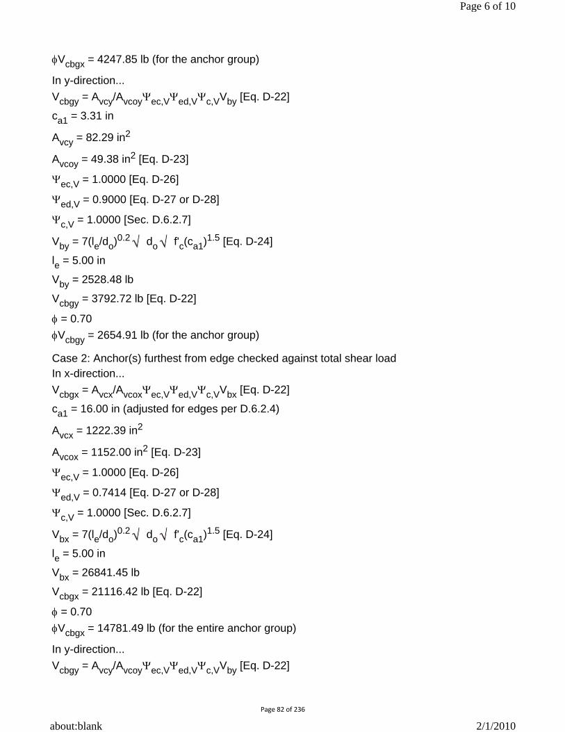
Vcbgx = 4247.85 lb (for the anchor group)
In y-direction...
Vcbgy = Avcy/Avcoyec,Ved,Vc,VVby [Eq. D-22]
ca1 = 3.31 in
Avcy = 82.29 in2
Avcoy = 49.38 in2 [Eq. D-23]
ec,V = 1.0000 [Eq. D-26]
ed,V = 0.9000 [Eq. D-27 or D-28]
c,V = 1.0000 [Sec. D.6.2.7]
Vby = 7(le/do)0.2 do f'c(ca1)1.5 [Eq. D-24]
le = 5.00 in
Vby = 2528.48 lb
Vcbgy = 3792.72 lb [Eq. D-22]
= 0.70
Vcbgy = 2654.91 lb (for the anchor group)
Case 2: Anchor(s) furthest from edge checked against total shear load In x-direction...
Vcbgx = Avcx/Avcoxec,Ved,Vc,VVbx [Eq. D-22]
ca1 = 16.00 in (adjusted for edges per D.6.2.4)
Avcx = 1222.39 in2
Avcox = 1152.00 in2 [Eq. D-23]
ec,V = 1.0000 [Eq. D-26]
ed,V = 0.7414 [Eq. D-27 or D-28]
c,V = 1.0000 [Sec. D.6.2.7]
Vbx = 7(le/do)0.2 do f'c(ca1)1.5 [Eq. D-24]
le = 5.00 in
Vbx = 26841.45 lb
Vcbgx = 21116.42 lb [Eq. D-22]
= 0.70
Vcbgx = 14781.49 lb (for the entire anchor group)
In y-direction...
Vcbgy = Avcy/Avcoyec,Ved,Vc,VVby [Eq. D-22]
Page 6 of 10
2/1/2010about:blank
Page 82 of 236

ca1 = 16.00 in (adjusted for edges per D.6.2.4)
Avcy = 576.00 in2
Avcoy = 1152.00 in2 [Eq. D-23]
ec,V = 1.0000 [Eq. D-26]
ed,V = 0.7414 [Eq. D-27 or D-28]
c,V = 1.0000 [Sec. D.6.2.7]
Vby = 7(le/do)0.2 do f'c(ca1)1.5 [Eq. D-24]
le = 5.00 in
Vby = 26841.45 lb
Vcbgy = 9950.21 lb [Eq. D-22]
= 0.70
Vcbgy = 6965.15 lb (for the entire anchor group)
Case 3: Anchor(s) closest to edge checked for parallel to edge condition Check anchors at cx1 edge
Vcbgx = Avcx/Avcoxec,Ved,Vc,VVbx [Eq. D-22]
ca1 = 3.31 in
Avcx = 131.67 in2
Avcox = 49.38 in2 [Eq. D-23]
ec,V = 1.0000 [Eq. D-26]
ed,V = 1.0000 [Sec. D.6.2.1(c)]
c,V = 1.0000 [Sec. D.6.2.7]
Vbx = 7(le/do)0.2 do f'c(ca1)1.5 [Eq. D-24]
le = 5.00 in
Vbx = 2528.48 lb
Vcbgx = 6742.62 lb [Eq. D-22]
Vcbgy = 2 * Vcbgx [Sec. D.6.2.1(c)]
Vcbgy = 13485.24 lb
= 0.70
Vcbgy = 9439.67 lb (for the anchor group)
Check anchors at cy1 edge
Vcbgy = Avcy/Avcoyec,Ved,Vc,VVby [Eq. D-22]
Page 7 of 10
2/1/2010about:blank
Page 83 of 236
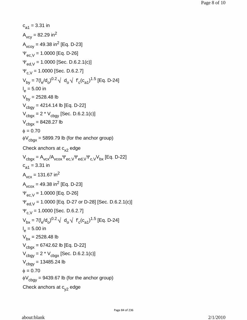
ca1 = 3.31 in
Avcy = 82.29 in2
Avcoy = 49.38 in2 [Eq. D-23]
ec,V = 1.0000 [Eq. D-26]
ed,V = 1.0000 [Sec. D.6.2.1(c)]
c,V = 1.0000 [Sec. D.6.2.7]
Vby = 7(le/do)0.2 do f'c(ca1)1.5 [Eq. D-24]
le = 5.00 in
Vby = 2528.48 lb
Vcbgy = 4214.14 lb [Eq. D-22]
Vcbgx = 2 * Vcbgy [Sec. D.6.2.1(c)]
Vcbgx = 8428.27 lb
= 0.70
Vcbgx = 5899.79 lb (for the anchor group)
Check anchors at cx2 edge
Vcbgx = Avcx/Avcoxec,Ved,Vc,VVbx [Eq. D-22]
ca1 = 3.31 in
Avcx = 131.67 in2
Avcox = 49.38 in2 [Eq. D-23]
ec,V = 1.0000 [Eq. D-26]
ed,V = 1.0000 [Eq. D-27 or D-28] [Sec. D.6.2.1(c)]
c,V = 1.0000 [Sec. D.6.2.7]
Vbx = 7(le/do)0.2 do f'c(ca1)1.5 [Eq. D-24]
le = 5.00 in
Vbx = 2528.48 lb
Vcbgx = 6742.62 lb [Eq. D-22]
Vcbgy = 2 * Vcbgx [Sec. D.6.2.1(c)]
Vcbgy = 13485.24 lb
= 0.70
Vcbgy = 9439.67 lb (for the anchor group)
Check anchors at cy2 edge
Page 8 of 10
2/1/2010about:blank
Page 84 of 236
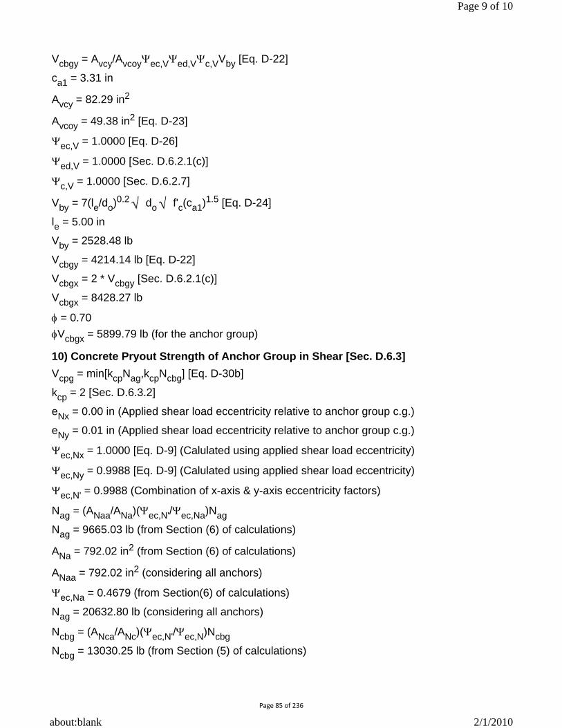
Vcbgy = Avcy/Avcoyec,Ved,Vc,VVby [Eq. D-22]
ca1 = 3.31 in
Avcy = 82.29 in2
Avcoy = 49.38 in2 [Eq. D-23]
ec,V = 1.0000 [Eq. D-26]
ed,V = 1.0000 [Sec. D.6.2.1(c)]
c,V = 1.0000 [Sec. D.6.2.7]
Vby = 7(le/do)0.2 do f'c(ca1)1.5 [Eq. D-24]
le = 5.00 in
Vby = 2528.48 lb
Vcbgy = 4214.14 lb [Eq. D-22]
Vcbgx = 2 * Vcbgy [Sec. D.6.2.1(c)]
Vcbgx = 8428.27 lb
= 0.70
Vcbgx = 5899.79 lb (for the anchor group)
10) Concrete Pryout Strength of Anchor Group in Shear [Sec. D.6.3]
Vcpg = min[kcpNag,kcpNcbg] [Eq. D-30b]
kcp = 2 [Sec. D.6.3.2]
eNx = 0.00 in (Applied shear load eccentricity relative to anchor group c.g.)
eNy = 0.01 in (Applied shear load eccentricity relative to anchor group c.g.)
ec,Nx = 1.0000 [Eq. D-9] (Calulated using applied shear load eccentricity)
ec,Ny = 0.9988 [Eq. D-9] (Calulated using applied shear load eccentricity)
ec,N' = 0.9988 (Combination of x-axis & y-axis eccentricity factors)
Nag = (ANaa/ANa)(ec,N'/ec,Na)Nag
Nag = 9665.03 lb (from Section (6) of calculations)
ANa = 792.02 in2 (from Section (6) of calculations)
ANaa = 792.02 in2 (considering all anchors)
ec,Na = 0.4679 (from Section(6) of calculations)
Nag = 20632.80 lb (considering all anchors)
Ncbg = (ANca/ANc)(ec,N'/ec,N)Ncbg
Ncbg = 13030.25 lb (from Section (5) of calculations)
Page 9 of 10
2/1/2010about:blank
Page 85 of 236

ANc = 792.02 in2 (from Section (5) of calculations)
ANca = 792.02 in2 (considering all anchors)
ec,N = 0.4679 (from Section(5) of calculations)
Ncbg = 27816.84 lb (considering all anchors)
Vcpg = 41265.61 lb
= 0.70 [D.4.4]
Vcpg = 28885.93 lb (for the anchor group)
11) Check Demand/Capacity Ratios [Sec. D.7]
Tension - Steel : 0.1913- Breakout : 0.6724- Adhesive : 0.9065- Sideface Blowout : N/A
Shear - Steel : 0.0000- Breakout (case 1) : 0.0000- Breakout (case 2) : 0.0000- Breakout (case 3) : 0.0000- Pryout : 0.0000
V.Max(0) <= 0.2 and T.Max(0.91) <= 1.0 [Sec D.7.1]
Interaction check: PASSUse 5/8" diameter A307 GR. C SET-XP anchor(s) with 5 in. embedment
Page 10 of 10
2/1/2010about:blank
Page 86 of 236

Page 87 of 236

Anchor Calculations
Anchor Designer for ACI 318 (Version 4.2.0.2)
Job Name : Borzal - Line 5-10 @ A (W) Date/Time : 2/4/2010 4:43:37 AM
Calculation Summary - ACI 318 Appendix D For Cracked Concrete
Anchor
Anchor Steel # of Anchors Embedment Depth (in) Category
3/4" Heavy Hex Bolt F1554 GR. 36 4 6 N/A
Concrete
Concrete Cracked f'c(psi) c,V
Normal weight Yes 2500.0 1.00
Condition Thickness (in) Suppl. Edge Reinforcement
A tension and shear 18 No
Factored Loads
Nua (lb) Vuax (lb) Vuay (lb) Mux (lb*ft) Muy (lb*ft)
8100 2900 0 0 0
ex(in) ey(in) Mod/high seismic Apply entire shear @ front row
0 0 No No
Individual Anchor Tension Loads
N ua1
(lb)
N ua2
(lb)
N ua3
(lb)
N ua4
(lb)
2025.00 2025.00 2025.00 2025.00
e'Nx(in) e'Ny(in)
0.00 0.00
Individual Anchor Shear Loads
V ua1
(lb)
V ua2
(lb)
V ua3
(lb)
V ua4
(lb)
725.00 725.00 725.00 725.00
e'Vx(in) e'Vy(in)
0.00 0.00
Tension Strengths
Steel ( = 0.75 )
Nsa(lb) Nsa(lb) Nua(lb) N ua /Nsa
19370 14527.50 2025.00 0.1394
Concrete Breakout ( = 0.75 )
Ncbg(lb) Ncbg(lb) Nua(lb) Nua /Ncbg
13070.34 9802.76 8100.00 0.8263
Page 1 of 2
2/4/2010about:blank
Page 88 of 236

Pullout ( = 0.70 )
Npn(lb) Npn(lb) Nua(lb) Nua /Npn
18220.00 12754.00 2025.00 0.1588
Side-Face Blowout does not apply
Shear Strengths
Steel ( = 0.65 )
Vsa(lb) Vsa (lb) Vua(lb) V ua /Vsa
11625 7556.25 725.00 0.0959
Concrete Breakout has not been evaluated per user option.
Pryout ( = 0.70 )
Vcpg(lb) Vcpg(lb) Vuax(lb) Vuax /Vcpg
26140.68 18298.48 2900 0.1585
Vcpg(lb) Vcpg(lb) Vuay(lb) Vuay /Vcpg Vua /Vcpg
26140.68 18298.48 0 0.0000 0.1585
Interaction check
V.Max(0.16) <= 0.2 and T.Max(0.83) <= 1.0 [Sec D.7.1]
Interaction check: PASS
Use 3/4" diameter F1554 GR. 36 Heavy Hex Bolt anchor(s) with 6 in. embedment
Page 2 of 2
2/4/2010about:blank
Page 89 of 236

Anchor Calculations
Anchor Designer for ACI 318 (Version 4.2.0.2)
Job Name : Borzal - Line 5-10 @ A (W) Date/Time : 2/4/2010 4:47:24 AM
Calculation Summary - ACI 318 Appendix D For Cracked Concrete
Anchor
Anchor Steel # of Anchors Embedment Depth (in) Category
3/4" Heavy Hex Bolt F1554 GR. 36 4 6 N/A
Concrete
Concrete Cracked f'c(psi) c,V
Normal weight Yes 2500.0 1.00
Condition Thickness (in) Suppl. Edge Reinforcement
A tension and shear 18 No
Factored Loads
Nua (lb) Vuax (lb) Vuay (lb) Mux (lb*ft) Muy (lb*ft)
-7100 -5300 0 0 0
ex(in) ey(in) Mod/high seismic Apply entire shear @ front row
0 0 No No
Individual Anchor Tension Loads
N
ua1
(lb)
N
ua2
(lb)
N
ua3
(lb)
N
ua4
(lb)
0.00 0.00 0.00 0.00
e'Nx(in) e'Ny(in)
0.00 0.00
Individual Anchor Shear Loads
V ua1
(lb)
V ua2
(lb)
V ua3
(lb)
V ua4
(lb)
1325.00 1325.00 1325.00 1325.00
e'Vx(in) e'Vy(in)
0.00 0.00
Tension Strengths
Steel ( = 0.75 )
Nsa(lb) Nsa(lb) Nua(lb) N ua /Nsa
19370 14527.50 0.00 0.0000
Concrete Breakout ( = 0.75 )
Ncbg(lb) Ncbg(lb) Nua(lb) Nua /Ncbg
13070.34 9802.76 0.00 0.0000
Page 1 of 2
2/4/2010about:blank
Page 90 of 236

Pullout ( = 0.70 )
Npn(lb) Npn(lb) Nua(lb) Nua /Npn
18220.00 12754.00 0.00 0.0000
Side-Face Blowout does not apply
Shear Strengths
Steel ( = 0.65 )
Vsa(lb) Vsa (lb) Vua(lb) V ua /Vsa
11625 7556.25 1325.00 0.1754
Concrete Breakout has not been evaluated per user option.
Pryout ( = 0.70 )
Vcpg(lb) Vcpg(lb) Vuax(lb) Vuax /Vcpg
26140.68 18298.48 -5300 0.2896
Vcpg(lb) Vcpg(lb) Vuay(lb) Vuay /Vcpg Vua /Vcpg
26140.68 18298.48 0 0.0000 0.2896
Interaction check
T.Max(0) <= 0.2 and V.Max(0.29) <= 1.0 [Sec D.7.2]
Interaction check: PASS
Use 3/4" diameter F1554 GR. 36 Heavy Hex Bolt anchor(s) with 6 in. embedment
Page 2 of 2
2/4/2010about:blank
Page 91 of 236

Anchor Calculations
Anchor Designer for ACI 318 (Version 4.2.0.2)
Job Name : Borzal - Line 5-10 @ A (EQ) Date/Time : 2/4/2010 4:48:57 AM
Calculation Summary - ACI 318 Appendix D For Cracked Concrete
Anchor
Anchor Steel # of Anchors Embedment Depth (in) Category
3/4" Heavy Hex Bolt F1554 GR. 36 4 6 N/A
Concrete
Concrete Cracked f'c(psi) c,V
Normal weight Yes 2500.0 1.00
Condition Thickness (in) Suppl. Edge Reinforcement
A tension and shear 18 No
Factored Loads
Nua (lb) Vuax (lb) Vuay (lb) Mux (lb*ft) Muy (lb*ft)
0 5200 0 0 0
ex(in) ey(in) Mod/high seismic Apply entire shear @ front row
0 0 Yes No
Individual Anchor Tension Loads
N
ua1
(lb)
N
ua2
(lb)
N
ua3
(lb)
N
ua4
(lb)
0.00 0.00 0.00 0.00
e'Nx(in) e'Ny(in)
0.00 0.00
Individual Anchor Shear Loads
V ua1
(lb)
V ua2
(lb)
V ua3
(lb)
V ua4
(lb)
1300.00 1300.00 1300.00 1300.00
e'Vx(in) e'Vy(in)
0.00 0.00
Tension Strengths
Steel ( = 0.75 )
Nsa(lb) Nsa(lb) Nua(lb) N ua /Nsa
19370 14527.50 0.00 0.0000
Concrete Breakout ( = 0.75 , seis = 0.75 )
Ncbg(lb) Ncbg(lb) Nua(lb) Nua /Ncbg
13070.34 7352.07 0.00 0.0000
Page 1 of 2
2/4/2010about:blank
Page 92 of 236

Pullout ( = 0.70 , seis = 0.75 )
Npn(lb) Npn(lb) Nua(lb) Nua /Npn
18220.00 9565.50 0.00 0.0000
Side-Face Blowout does not apply
Shear Strengths
Steel ( = 0.65 )
Veq(lb) Veq(lb) Vua(lb) V ua /Veq
11625 7556.25 1300.00 0.1720
Concrete Breakout has not been evaluated per user option.
Pryout ( = 0.70 , seis = 0.75 )
Vcpg(lb) Vcpg(lb) Vuax(lb) Vuax /Vcpg
26140.68 13723.86 5200 0.3789
Vcpg(lb) Vcpg(lb) Vuay(lb) Vuay /Vcpg Vua /Vcpg
26140.68 13723.86 0 0.0000 0.3789
Interaction check
T.Max(0) <= 0.2 and V.Max(0.38) <= 1.0 [Sec D.7.2]
Interaction check: PASS
Use 3/4" diameter F1554 GR. 36 Heavy Hex Bolt anchor(s) with 6 in. embedment
BRITTLE FAILURE GOVERNS: Governing anchor failure mode is brittle failure. Per 2006 IBC Section 1908.1.16, anchors shall be governed by a ductile steel element in structures assigned to Seismic Design Category C, D, E, or F. Alternatively the minimum design strength of the anchor(s) shall be at least 2.5 times the factored forces or the anchor attachment to the structure shall undergo ductile yielding at a load level less than the design strength of the anchor(s). Designer must exercise own judgement to determine if this design is suitable.
Page 2 of 2
2/4/2010about:blank
Page 93 of 236

Anchor Calculations
Anchor Designer for ACI 318 (Version 4.2.0.2)
Job Name : Borzal - Line 5-10 @ A (EQ) Date/Time : 2/4/2010 4:51:31 AM
Calculation Summary - ACI 318 Appendix D For Cracked Concrete
Anchor
Anchor Steel # of Anchors Embedment Depth (in) Category
3/4" Heavy Hex Bolt F1554 GR. 36 4 6 N/A
Concrete
Concrete Cracked f'c(psi) c,V
Normal weight Yes 2500.0 1.00
Condition Thickness (in) Suppl. Edge Reinforcement
A tension and shear 18 No
Factored Loads
Nua (lb) Vuax (lb) Vuay (lb) Mux (lb*ft) Muy (lb*ft)
0 -400 0 0 0
ex(in) ey(in) Mod/high seismic Apply entire shear @ front row
0 0 Yes No
Individual Anchor Tension Loads
N
ua1
(lb)
N
ua2
(lb)
N
ua3
(lb)
N
ua4
(lb)
0.00 0.00 0.00 0.00
e'Nx(in) e'Ny(in)
0.00 0.00
Individual Anchor Shear Loads
V ua1
(lb)
V ua2
(lb)
V ua3
(lb)
V ua4
(lb)
100.00 100.00 100.00 100.00
e'Vx(in) e'Vy(in)
0.00 0.00
Tension Strengths
Steel ( = 0.75 )
Nsa(lb) Nsa(lb) Nua(lb) N ua /Nsa
19370 14527.50 0.00 0.0000
Concrete Breakout ( = 0.75 , seis = 0.75 )
Ncbg(lb) Ncbg(lb) Nua(lb) Nua /Ncbg
13070.34 7352.07 0.00 0.0000
Page 1 of 2
2/4/2010about:blank
Page 94 of 236

Pullout ( = 0.70 , seis = 0.75 )
Npn(lb) Npn(lb) Nua(lb) Nua /Npn
18220.00 9565.50 0.00 0.0000
Side-Face Blowout does not apply
Shear Strengths
Steel ( = 0.65 )
Veq(lb) Veq(lb) Vua(lb) V ua /Veq
11625 7556.25 100.00 0.0132
Concrete Breakout has not been evaluated per user option.
Pryout ( = 0.70 , seis = 0.75 )
Vcpg(lb) Vcpg(lb) Vuax(lb) Vuax /Vcpg
26140.68 13723.86 -400 0.0291
Vcpg(lb) Vcpg(lb) Vuay(lb) Vuay /Vcpg Vua /Vcpg
26140.68 13723.86 0 0.0000 0.0291
Interaction check
V.Max(0.03) <= 0.2 and T.Max(0) <= 1.0 [Sec D.7.1]
Interaction check: PASS
Use 3/4" diameter F1554 GR. 36 Heavy Hex Bolt anchor(s) with 6 in. embedment
BRITTLE FAILURE GOVERNS: Governing anchor failure mode is brittle failure. Per 2006 IBC Section 1908.1.16, anchors shall be governed by a ductile steel element in structures assigned to Seismic Design Category C, D, E, or F. Alternatively the minimum design strength of the anchor(s) shall be at least 2.5 times the factored forces or the anchor attachment to the structure shall undergo ductile yielding at a load level less than the design strength of the anchor(s). Designer must exercise own judgement to determine if this design is suitable.
Page 2 of 2
2/4/2010about:blank
Page 95 of 236
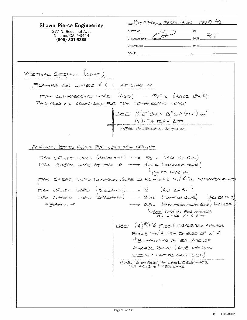
Page 96 of 236

General Footing Design ENERCALC, INC. 1983-2009, Ver: 6.1.01, N:40336License Owner : PIERCE ENGINEERINGLic. # : KW-06008640
File: Z:\@Shawn Pierce Engineering\09_Projects\Borzal Addition_02\Engineering\Design\melford borzall expansion.ec6Printed: 1 FEB 2010, 6:06AM
Description : Pad Footing at Lines 4 & 11 - Line W
Shawn Pierce Engineering277 N. Beechnut AveNipomo, CA 93444Phone: (805) 801-9385Email: [email protected]
Title : Melford Borzall Expansion Job # 09.9-2/2
Project Desc.:Dsgnr: Shawn D. Pierce
Project Notes :
Calculations per IBC 2006, CBC 2007, ACI 318-05General Information
Material Properties Soil Design Values2.0
Analysis Settings
350.0ksiNo
ksfAllowable Soil Bearing ==
2.5060.0
2,850.0145.0
0.00140
= 0.350Flexure = 0.90Shear =
Values
0.00180
0.0
Soil Passive Resistance (for Sliding)
1.501.50
=
Increases based on footing Width
:AutoCalc Pedestal Weight as DL No
Allow. Pressure Increase per foot of width = 0.0 ksfwhen footing is wider than = 0.0 ft
:
=
AutoCalc Footing Weight as DL No
when base footing is below 0.0 ft
pcf
Increase Bearing By Footing Weight= pcf
Min. Overturning Safety Factor=
: 1
Increases based on footing Depth0.850=
Soil/Concrete Friction Coeff.Ec : Concrete Elastic Modulus
Min. Sliding Safety Factor=
=
: 1
Reference Depth below Surface0.0
ft=Allow. Pressure Increase per foot of depth ksf
=
=
=
Concrete Density
=
Min Allow % Temp Reinf.
ksif'c : Concrete 28 day strengthFy : Rebar Yield ksi
Min Steel % Bending Reinf.
Edge D
ist. = 3"
2'-3"
2'-3
"
Z
Z
X X
2 - # 5 Bars3.3
13" X-X Section Looking to +Z 2 - # 5 Bars
3.3
13"
Z-Z Section Looking to +X
#
Dimensions
Width along X-X Axis 2.250 ftLength along Z-Z Axis
=2.250 ft
Load location offset from footing center...ex : Along X-X Axis 0 inez : Along Z-Z Axis 0 in
=Pedestal dimensions...
==
px : Along X-X Axis 0.0 inpz : Along Z-Z Axis 0.0 inHeight =
=0.0 in
Footing Thickness=
18.0 in=
Rebar Centerline to Edge of Concrete...= inat Bottom of footing 3.313
Reinforcing
#
Bars along X-X Axis
Reinforcing Bar Size=
5Number of Bars
=2.0
Bars along Z-Z Axis
Reinforcing Bar Size = 5Number of Bars = 2.0
Bandwidth Distribution Check (ACI 15.4.4.2)Direction Requiring Closer Separation n/a# Bars required within zone n/a# Bars required on each side of zone n/a
Applied Loads
5.20 4.70 0.0 0.0 0.0 1.90 0.00.0 0.0 0.0 0.0 0.0 0.0 0.0
D Lr
ksf
L SP : Column LoadOB : Overburden =
kW E
M-zzV-x
== 0.0 k
0.00.0 0.0 0.0 0.0 0.0
V-z 0.0 k0.0 0.0 0.0 0.0 0.00.0
0.0 0.0M-xx =
0.0 k-ft= 0.0 0.00.0 k-ft
0.00.0
0.00.0 0.0 0.0 0.0 0.0
H=
Page 97 of 236

General Footing Design ENERCALC, INC. 1983-2009, Ver: 6.1.01, N:40336License Owner : PIERCE ENGINEERINGLic. # : KW-06008640
File: Z:\@Shawn Pierce Engineering\09_Projects\Borzal Addition_02\Engineering\Design\melford borzall expansion.ec6Printed: 1 FEB 2010, 6:06AM
Description : Pad Footing at Lines 4 & 11 - Line W
Shawn Pierce Engineering277 N. Beechnut AveNipomo, CA 93444Phone: (805) 801-9385Email: [email protected]
Title : Melford Borzall Expansion Job # 09.9-2/2
Project Desc.:Dsgnr: Shawn D. Pierce
Project Notes :
DESIGN SUMMARY Design OK
Governing Load CombinationMin. Ratio Item Applied CapacityPASS 0.9780 Soil Bearing 1.956 ksf 2.0 ksf +D+Lr+HPASS n/a Overturning - X-X 0.0 k-ft 0.0 k-ft No OverturningPASS n/a Overturning - Z-Z 0.0 k-ft 0.0 k-ft No OverturningPASS n/a Sliding - X-X 0.0 k 0.0 k No SlidingPASS n/a Sliding - Z-Z 0.0 k 0.0 k No SlidingPASS n/a Uplift 0.0 k 0.0 k No UpliftPASS 0.09656 Z Flexure (+X) 1.720 k-ft 17.810 k-ft +1.20D+1.60Lr+0.50LPASS 0.09656 Z Flexure (-X) 1.720 k-ft 17.810 k-ft +1.20D+1.60Lr+0.50LPASS 0.09656 X Flexure (+Z) 1.720 k-ft 17.810 k-ft +1.20D+1.60Lr+0.50LPASS 0.09656 X Flexure (-Z) 1.720 k-ft 17.810 k-ft +1.20D+1.60Lr+0.50LPASS n/a 1-way Shear (+X) 0.0 psi 85.0 psi n/aPASS 0.0 1-way Shear (-X) 0.0 psi 0.0 psi n/aPASS n/a 1-way Shear (+Z) 0.0 psi 85.0 psi n/aPASS n/a 1-way Shear (-Z) 0.0 psi 85.0 psi n/aPASS n/a 2-way Punching 11.182 psi 85.0 psi +1.20D+1.60Lr+0.50L
Detailed Results
Rotation Axis &ZeccXecc
Actual Soil Bearing Stress Actual / AllowableSoil Bearing
Gross Allowable +Z +Z -X -X RatioLoad Combination...X-X, +D 2.0 n/a1.027 1.027 n/a 0.5140.0n/aX-X, +D+L+H 2.0 n/a1.027 1.027 n/a 0.5140.0n/aX-X, +D+Lr+H 2.0 n/a1.956 1.956 n/a 0.9780.0n/aX-X, +D+0.750Lr+0.750L+H 2.0 n/a1.723 1.723 n/a 0.8620.0n/aX-X, +D+0.70E+H 2.0 n/a1.290 1.290 n/a 0.6450.0n/aX-X, +D+0.750Lr+0.750L+0.5250E+H 2.0 n/a1.920 1.920 n/a 0.9600.0n/aX-X, +D+0.750L+0.750S+0.5250E+H 2.0 n/a1.224 1.224 n/a 0.6120.0n/aX-X, +0.60D+0.70E+H 2.0 n/a0.8790 0.8790 n/a 0.4400.0n/aZ-Z, +D 2.0 1.027n/a n/a 1.027 0.514n/a0.0Z-Z, +D+L+H 2.0 1.027n/a n/a 1.027 0.514n/a0.0Z-Z, +D+Lr+H 2.0 1.956n/a n/a 1.956 0.978n/a0.0Z-Z, +D+0.750Lr+0.750L+H 2.0 1.723n/a n/a 1.723 0.862n/a0.0Z-Z, +D+0.70E+H 2.0 1.290n/a n/a 1.290 0.645n/a0.0Z-Z, +D+0.750Lr+0.750L+0.5250E+H 2.0 1.920n/a n/a 1.920 0.960n/a0.0Z-Z, +D+0.750L+0.750S+0.5250E+H 2.0 1.224n/a n/a 1.224 0.612n/a0.0Z-Z, +0.60D+0.70E+H 2.0 0.8790n/a n/a 0.8790 0.440n/a0.0
Rotation Axis &Overturning Stability
Load Combination... StatusOverturning Moment Resisting Moment Stability RatioFooting Has NO Overturning
Force Application AxisSliding Stability
Load Combination... StatusSliding Force Resisting Force Sliding SafetyRatioFooting Has NO Sliding
Footing FlexureAs Req'd
Footing FlexureTension @ Bot.Which
Actual As StatusMu Side ? or Top ? Gvrn. As Phi*MnLoad Combination...Z-Z, +0.90D+E+1.60H 0.8224 k-ft +X Bottom 0.01 in2/ft Bending 0.28 in2/ft 17.810 k-ft OKZ-Z, +0.90D+E+1.60H 0.8224 k-ft +X Bottom 0.01 in2/ft Bending 0.28 in2/ft 17.810 k-ft OKZ-Z, +0.90D+E+1.60H 0.8224 k-ft +X Bottom 0.01 in2/ft Bending 0.28 in2/ft 17.810 k-ft OKZ-Z, +0.90D+E+1.60H 0.8224 k-ft +X Bottom 0.01 in2/ft Bending 0.28 in2/ft 17.810 k-ft OKZ-Z, +0.90D+E+1.60H 0.8224 k-ft +X Bottom 0.01 in2/ft Bending 0.28 in2/ft 17.810 k-ft OKZ-Z, +0.90D+E+1.60H 0.8224 k-ft +X Bottom 0.01 in2/ft Bending 0.28 in2/ft 17.810 k-ft OKZ-Z, +0.90D+E+1.60H 0.8224 k-ft +X Bottom 0.01 in2/ft Bending 0.28 in2/ft 17.810 k-ft OKZ-Z, +0.90D+E+1.60H 0.8224 k-ft +X Bottom 0.01 in2/ft Bending 0.28 in2/ft 17.810 k-ft OKZ-Z, +0.90D+E+1.60H 0.8224 k-ft +X Bottom 0.01 in2/ft Bending 0.28 in2/ft 17.810 k-ft OKZ-Z, +0.90D+E+1.60H 0.8224 k-ft +X Bottom 0.01 in2/ft Bending 0.28 in2/ft 17.810 k-ft OK
Page 98 of 236

General Footing Design ENERCALC, INC. 1983-2009, Ver: 6.1.01, N:40336License Owner : PIERCE ENGINEERINGLic. # : KW-06008640
File: Z:\@Shawn Pierce Engineering\09_Projects\Borzal Addition_02\Engineering\Design\melford borzall expansion.ec6Printed: 1 FEB 2010, 6:06AM
Description : Pad Footing at Lines 4 & 11 - Line W
Shawn Pierce Engineering277 N. Beechnut AveNipomo, CA 93444Phone: (805) 801-9385Email: [email protected]
Title : Melford Borzall Expansion Job # 09.9-2/2
Project Desc.:Dsgnr: Shawn D. Pierce
Project Notes :
Z-Z, +0.90D+E+1.60H 0.8224 k-ft +X Bottom 0.01 in2/ft Bending 0.28 in2/ft 17.810 k-ft OKZ-Z, +0.90D+E+1.60H 0.8224 k-ft +X Bottom 0.01 in2/ft Bending 0.28 in2/ft 17.810 k-ft OK
Page 99 of 236

General Footing Design ENERCALC, INC. 1983-2009, Ver: 6.1.01, N:40336License Owner : PIERCE ENGINEERINGLic. # : KW-06008640
File: Z:\@Shawn Pierce Engineering\09_Projects\Borzal Addition_02\Engineering\Design\melford borzall expansion.ec6Printed: 1 FEB 2010, 6:06AM
Description : Pad Footing at Lines 4 & 11 - Line W
Shawn Pierce Engineering277 N. Beechnut AveNipomo, CA 93444Phone: (805) 801-9385Email: [email protected]
Title : Melford Borzall Expansion Job # 09.9-2/2
Project Desc.:Dsgnr: Shawn D. Pierce
Project Notes :
Footing FlexureAs Req'd
Footing FlexureTension @ Bot.Which
Actual As StatusMu Side ? or Top ? Gvrn. As Phi*MnLoad Combination...Z-Z, +0.90D+E+1.60H 0.8224 k-ft +X Bottom 0.01 in2/ft Bending 0.28 in2/ft 17.810 k-ft OKZ-Z, +0.90D+E+1.60H 0.8224 k-ft +X Bottom 0.01 in2/ft Bending 0.28 in2/ft 17.810 k-ft OKZ-Z, +0.90D+E+1.60H 0.8224 k-ft +X Bottom 0.01 in2/ft Bending 0.28 in2/ft 17.810 k-ft OKZ-Z, +0.90D+E+1.60H 0.8224 k-ft +X Bottom 0.01 in2/ft Bending 0.28 in2/ft 17.810 k-ft OKZ-Z, +0.90D+E+1.60H 0.8224 k-ft +X Bottom 0.01 in2/ft Bending 0.28 in2/ft 17.810 k-ft OKZ-Z, +0.90D+E+1.60H 0.8224 k-ft +X Bottom 0.01 in2/ft Bending 0.28 in2/ft 17.810 k-ft OKZ-Z, +0.90D+E+1.60H 0.8224 k-ft +X Bottom 0.01 in2/ft Bending 0.28 in2/ft 17.810 k-ft OKZ-Z, +0.90D+E+1.60H 0.8224 k-ft +X Bottom 0.01 in2/ft Bending 0.28 in2/ft 17.810 k-ft OKZ-Z, +0.90D+E+1.60H 0.8224 k-ft +X Bottom 0.01 in2/ft Bending 0.28 in2/ft 17.810 k-ft OKZ-Z, +0.90D+E+1.60H 0.8224 k-ft +X Bottom 0.01 in2/ft Bending 0.28 in2/ft 17.810 k-ft OKOne Way Shear
Vu @ +XLoad Combination... Vu @ -X Vu @ -Z Vu @ +Z Vu:Max Phi*Vn / VuPhi Vn Status+0.90D+E+1.60H 0.0 0.0 0.0 0.0 0.0 85.0 0.0psipsipsipsipsipsi OK+0.90D+E+1.60H 0.0 0.0 0.0 0.0 0.0 85.0 0.0psipsipsipsipsipsi OK+0.90D+E+1.60H 0.0 0.0 0.0 0.0 0.0 85.0 0.0psipsipsipsipsipsi OK+0.90D+E+1.60H 0.0 0.0 0.0 0.0 0.0 85.0 0.0psipsipsipsipsipsi OK+0.90D+E+1.60H 0.0 0.0 0.0 0.0 0.0 85.0 0.0psipsipsipsipsipsi OK
Vu / Phi*VnPunching Shear
StatusVu Phi*VnLoad Combination...+0.90D+E+1.60H 5.347 170.0 0.03145 OKpsipsi+0.90D+E+1.60H 5.347 170.0 0.03145 OKpsipsi+0.90D+E+1.60H 5.347 170.0 0.03145 OKpsipsi+0.90D+E+1.60H 5.347 170.0 0.03145 OKpsipsi+0.90D+E+1.60H 5.347 170.0 0.03145 OKpsipsi
Page 100 of 236

Anchor Calculations
Anchor Designer for ACI 318 (Version 4.2.0.2)
Job Name : Borzal - Line 4 & 11 @ W Date/Time : 2/1/2010 6:19:05 AM
Calculation Summary - ACI 318 Appendix D For Cracked Concrete
Anchor
Anchor Steel # of Anchors Embedment Depth (in) Category
3/4" Heavy Hex Bolt F1554 GR. 36 4 6 N/A
Concrete
Concrete Cracked f'c(psi) c,V
Normal weight Yes 2500.0 1.00
Condition Thickness (in) Suppl. Edge Reinforcement
A tension and shear 18 No
Factored Loads
Nua (lb) Vuax (lb) Vuay (lb) Mux (lb*ft) Muy (lb*ft)
9600 0 4600 0 0
ex(in) ey(in) Mod/high seismic Apply entire shear @ front row
0 0 No No
Individual Anchor Tension Loads
N ua1
(lb)
N ua2
(lb)
N ua3
(lb)
N ua4
(lb)
2400.00 2400.00 2400.00 2400.00
e'Nx(in) e'Ny(in)
0.00 0.00
Individual Anchor Shear Loads
V ua1
(lb)
V ua2
(lb)
V ua3
(lb)
V ua4
(lb)
1150.00 1150.00 1150.00 1150.00
e'Vx(in) e'Vy(in)
0.00 0.00
Tension Strengths
Steel ( = 0.75 )
Nsa(lb) Nsa(lb) Nua(lb) N ua /Nsa
19370 14527.50 2400.00 0.1652
Concrete Breakout ( = 0.75 )
Ncbg(lb) Ncbg(lb) Nua(lb) Nua /Ncbg
20457.93 15343.45 9600.00 0.6257
Page 1 of 2
2/1/2010about:blank
Page 101 of 236

Pullout ( = 0.70 )
Npn(lb) Npn(lb) Nua(lb) Nua /Npn
18220.00 12754.00 2400.00 0.1882
Side-Face Blowout does not apply
Shear Strengths
Steel ( = 0.65 )
Vsa(lb) Vsa (lb) Vua(lb) V ua /Vsa
11625 7556.25 1150.00 0.1522
Concrete Breakout has not been evaluated per user option.
Pryout ( = 0.70 )
Vcpg(lb) Vcpg(lb) Vuax(lb) Vuax /Vcpg
40915.85 28641.10 0 0.0000
Vcpg(lb) Vcpg(lb) Vuay(lb) Vuay /Vcpg Vua /Vcpg
40915.85 28641.10 4600 0.1606 0.1606
Interaction check
V.Max(0.16) <= 0.2 and T.Max(0.63) <= 1.0 [Sec D.7.1]
Interaction check: PASS
Use 3/4" diameter F1554 GR. 36 Heavy Hex Bolt anchor(s) with 6 in. embedment
Page 2 of 2
2/1/2010about:blank
Page 102 of 236

Anchor Calculations
Anchor Designer for ACI 318 (Version 4.2.0.2)
Job Name : Borzal - Line 4 & 11 @ W Date/Time : 2/1/2010 6:20:38 AM
Calculation Summary - ACI 318 Appendix D For Cracked Concrete
Anchor
Anchor Steel # of Anchors Embedment Depth (in) Category
3/4" Heavy Hex Bolt F1554 GR. 36 4 6 N/A
Concrete
Concrete Cracked f'c(psi) c,V
Normal weight Yes 2500.0 1.00
Condition Thickness (in) Suppl. Edge Reinforcement
A tension and shear 18 No
Factored Loads
Nua (lb) Vuax (lb) Vuay (lb) Mux (lb*ft) Muy (lb*ft)
-4700 0 -6400 0 0
ex(in) ey(in) Mod/high seismic Apply entire shear @ front row
0 0 No No
Individual Anchor Tension Loads
N
ua1
(lb)
N
ua2
(lb)
N
ua3
(lb)
N
ua4
(lb)
0.00 0.00 0.00 0.00
e'Nx(in) e'Ny(in)
0.00 0.00
Individual Anchor Shear Loads
V ua1
(lb)
V ua2
(lb)
V ua3
(lb)
V ua4
(lb)
1600.00 1600.00 1600.00 1600.00
e'Vx(in) e'Vy(in)
0.00 0.00
Tension Strengths
Steel ( = 0.75 )
Nsa(lb) Nsa(lb) Nua(lb) N ua /Nsa
19370 14527.50 0.00 0.0000
Concrete Breakout ( = 0.75 )
Ncbg(lb) Ncbg(lb) Nua(lb) Nua /Ncbg
20457.93 15343.45 0.00 0.0000
Page 1 of 2
2/1/2010about:blank
Page 103 of 236

Pullout ( = 0.70 )
Npn(lb) Npn(lb) Nua(lb) Nua /Npn
18220.00 12754.00 0.00 0.0000
Side-Face Blowout does not apply
Shear Strengths
Steel ( = 0.65 )
Vsa(lb) Vsa (lb) Vua(lb) V ua /Vsa
11625 7556.25 1600.00 0.2117
Concrete Breakout has not been evaluated per user option.
Pryout ( = 0.70 )
Vcpg(lb) Vcpg(lb) Vuax(lb) Vuax /Vcpg
40915.85 28641.10 0 0.0000
Vcpg(lb) Vcpg(lb) Vuay(lb) Vuay /Vcpg Vua /Vcpg
40915.85 28641.10 -6400 0.2235 0.2235
Interaction check
T.Max(0) <= 0.2 and V.Max(0.22) <= 1.0 [Sec D.7.2]
Interaction check: PASS
Use 3/4" diameter F1554 GR. 36 Heavy Hex Bolt anchor(s) with 6 in. embedment
Page 2 of 2
2/1/2010about:blank
Page 104 of 236

Page 105 of 236

*Assume Cantilever Footing
*Weight of Ftg. approx.
replacing the weight of soil removed
Footing Information
width 24 in width 24 in a 0.729 inheight 18 in depth 15 in Mu 40.832 k-ftf'c 2500 psi f'c 2.5 ksiFb 2000 psf per soils report or
CBC min. fy 60 ksi L' 12.80 ft
Reinforcing Steel As 0.62 in2
6 AFtg 3.00 ft3/ft Fb(allow) 1780 psfFb 2000 psf Vc 63.3 psi
FALSE Vu 85.0 psiwDL (psf) wLL (psf) Trib (ft)
wDL Roof 78 0 5 Roof 390 plfwDL Wall 0 0 0 Wall 0 plf
wDL 2nd Flr. 0 0 0 2nd Flr 0 plf
Ftg. n/a plf Pmax 30,600 lbs
Slab 50 plfSum 440 plf
SHEAR GOVERNED
Calcs (cont.)
Dead Loads
Max Point Load @ (E) Footing
Input Calcs
Results
Equations
Pmax
L' = Length at which footing eliminates downward load
(2) #5 T&B
ftgallowb
cuftgftg
bc
ftg
actualDLballowb
DLDL
u
DLGuidedFixedMax
c
ys
aysnu
bLFPfinally
fVdb
LFV
bFFLet
LPM
Lso
LM
bf
fAawhere
dfAMM
)2(:
22
27.1
3...
3
7.1
9.085.
...
)(max
)()(
max
2
)(
2
Two Story
Page 106 of 236
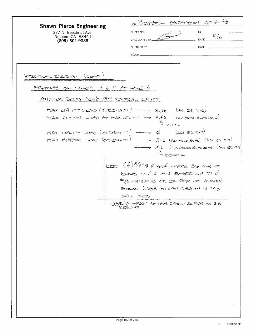
Page 107 of 236

Anchor Calculations
Anchor Designer for ACI 318 (Version 4.2.0.2)
Job Name : Borzal - Line 4-11 @ A (W) Date/Time : 2/4/2010 5:14:24 AM
Calculation Summary - ACI 318 Appendix D For Cracked Concrete
Anchor
Anchor Steel # of Anchors Embedment Depth (in) Category
3/4" Heavy Hex Bolt F1554 GR. 36 4 7 N/A
Concrete
Concrete Cracked f'c(psi) c,V
Normal weight Yes 2500.0 1.00
Condition Thickness (in) Suppl. Edge Reinforcement
A tension and shear 18 No
Factored Loads
Nua (lb) Vuax (lb) Vuay (lb) Mux (lb*ft) Muy (lb*ft)
8100 -4400 0 0 0
ex(in) ey(in) Mod/high seismic Apply entire shear @ front row
0 0 No No
Individual Anchor Tension Loads
N ua1
(lb)
N ua2
(lb)
N ua3
(lb)
N ua4
(lb)
2025.00 2025.00 2025.00 2025.00
e'Nx(in) e'Ny(in)
0.00 0.00
Individual Anchor Shear Loads
V ua1
(lb)
V ua2
(lb)
V ua3
(lb)
V ua4
(lb)
1100.00 1100.00 1100.00 1100.00
e'Vx(in) e'Vy(in)
0.00 0.00
Tension Strengths
Steel ( = 0.75 )
Nsa(lb) Nsa(lb) Nua(lb) N ua /Nsa
19370 14527.50 2025.00 0.1394
Concrete Breakout ( = 0.75 )
Ncbg(lb) Ncbg(lb) Nua(lb) Nua /Ncbg
14952.98 11214.74 8100.00 0.7223
Page 1 of 2
2/4/2010about:blank
Page 108 of 236

Pullout ( = 0.70 )
Npn(lb) Npn(lb) Nua(lb) Nua /Npn
18220.00 12754.00 2025.00 0.1588
Side-Face Blowout does not apply
Shear Strengths
Steel ( = 0.65 )
Vsa(lb) Vsa (lb) Vua(lb) V ua /Vsa
11625 7556.25 1100.00 0.1456
Concrete Breakout has not been evaluated per user option.
Pryout ( = 0.70 )
Vcpg(lb) Vcpg(lb) Vuax(lb) Vuax /Vcpg
29905.96 20934.17 -4400 0.2102
Vcpg(lb) Vcpg(lb) Vuay(lb) Vuay /Vcpg Vua /Vcpg
29905.96 20934.17 0 0.0000 0.2102
Interaction check
T.Max(0.72) + V.Max(0.21) = 0.93 <= 1.2 [Sec D.7.3]
Interaction check: PASS
Use 3/4" diameter F1554 GR. 36 Heavy Hex Bolt anchor(s) with 7 in. embedment
Page 2 of 2
2/4/2010about:blank
Page 109 of 236

Anchor Calculations
Anchor Designer for ACI 318 (Version 4.2.0.2)
Job Name : Borzal - Line 4-11 @ A (EQ-) Date/Time : 2/4/2010 5:16:18 AM
Calculation Summary - ACI 318 Appendix D For Cracked Concrete
Anchor
Anchor Steel # of Anchors Embedment Depth (in) Category
3/4" Heavy Hex Bolt F1554 GR. 36 4 7 N/A
Concrete
Concrete Cracked f'c(psi) c,V
Normal weight Yes 2500.0 1.00
Condition Thickness (in) Suppl. Edge Reinforcement
A tension and shear 18 No
Factored Loads
Nua (lb) Vuax (lb) Vuay (lb) Mux (lb*ft) Muy (lb*ft)
0 3100 0 0 0
ex(in) ey(in) Mod/high seismic Apply entire shear @ front row
0 0 Yes No
Individual Anchor Tension Loads
N
ua1
(lb)
N
ua2
(lb)
N
ua3
(lb)
N
ua4
(lb)
0.00 0.00 0.00 0.00
e'Nx(in) e'Ny(in)
0.00 0.00
Individual Anchor Shear Loads
V ua1
(lb)
V ua2
(lb)
V ua3
(lb)
V ua4
(lb)
775.00 775.00 775.00 775.00
e'Vx(in) e'Vy(in)
0.00 0.00
Tension Strengths
Steel ( = 0.75 )
Nsa(lb) Nsa(lb) Nua(lb) N ua /Nsa
19370 14527.50 0.00 0.0000
Concrete Breakout ( = 0.75 , seis = 0.75 )
Ncbg(lb) Ncbg(lb) Nua(lb) Nua /Ncbg
14952.98 8411.05 0.00 0.0000
Page 1 of 2
2/4/2010about:blank
Page 110 of 236

Pullout ( = 0.70 , seis = 0.75 )
Npn(lb) Npn(lb) Nua(lb) Nua /Npn
18220.00 9565.50 0.00 0.0000
Side-Face Blowout does not apply
Shear Strengths
Steel ( = 0.65 )
Veq(lb) Veq(lb) Vua(lb) V ua /Veq
11625 7556.25 775.00 0.1026
Concrete Breakout has not been evaluated per user option.
Pryout ( = 0.70 , seis = 0.75 )
Vcpg(lb) Vcpg(lb) Vuax(lb) Vuax /Vcpg
29905.96 15700.63 3100 0.1974
Vcpg(lb) Vcpg(lb) Vuay(lb) Vuay /Vcpg Vua /Vcpg
29905.96 15700.63 0 0.0000 0.1974
Interaction check
V.Max(0.2) <= 0.2 and T.Max(0) <= 1.0 [Sec D.7.1]
Interaction check: PASS
Use 3/4" diameter F1554 GR. 36 Heavy Hex Bolt anchor(s) with 7 in. embedment
BRITTLE FAILURE GOVERNS: Governing anchor failure mode is brittle failure. Per 2006 IBC Section 1908.1.16, anchors shall be governed by a ductile steel element in structures assigned to Seismic Design Category C, D, E, or F. Alternatively the minimum design strength of the anchor(s) shall be at least 2.5 times the factored forces or the anchor attachment to the structure shall undergo ductile yielding at a load level less than the design strength of the anchor(s). Designer must exercise own judgement to determine if this design is suitable.
Page 2 of 2
2/4/2010about:blank
Page 111 of 236

Page 112 of 236

Page 113 of 236

General Footing Design ENERCALC, INC. 1983-2009, Ver: 6.1.01, N:40336License Owner : PIERCE ENGINEERINGLic. # : KW-06008640
File: Z:\@Shawn Pierce Engineering\09_Projects\Borzal Addition_02\Engineering\Design\melford borzall expansion.ec6Printed: 1 FEB 2010, 6:32AM
Description : Pad Footing at Lines 2-10.1 - Line P
Shawn Pierce Engineering277 N. Beechnut AveNipomo, CA 93444Phone: (805) 801-9385Email: [email protected]
Title : Melford Borzall Expansion Job # 09.9-2/2
Project Desc.:Dsgnr: Shawn D. Pierce
Project Notes :
Calculations per IBC 2006, CBC 2007, ACI 318-05General Information
Material Properties Soil Design Values2.660
Analysis Settings
350.0ksiNo
ksfAllowable Soil Bearing ==
2.5060.0
2,850.0145.0
0.00140
= 0.350Flexure = 0.90Shear =
Values
0.00180
0.0
Soil Passive Resistance (for Sliding)
1.501.50
=
Increases based on footing Width
:AutoCalc Pedestal Weight as DL No
Allow. Pressure Increase per foot of width = 0.0 ksfwhen footing is wider than = 0.0 ft
:
=
AutoCalc Footing Weight as DL No
when base footing is below 0.0 ft
pcf
Increase Bearing By Footing Weight= pcf
Min. Overturning Safety Factor=
: 1
Increases based on footing Depth0.850=
Soil/Concrete Friction Coeff.Ec : Concrete Elastic Modulus
Min. Sliding Safety Factor=
=
: 1
Reference Depth below Surface0.0
ft=Allow. Pressure Increase per foot of depth ksf
=
=
=
Concrete Density
=
Min Allow % Temp Reinf.
ksif'c : Concrete 28 day strengthFy : Rebar Yield ksi
Min Steel % Bending Reinf.
Ed
ge
Dist. =
3"
2'-3"
2'-3
"
Z
Z
X X
2 - # 5 Bars3.3
13" X-X Section Looking to +Z
2 - # 5 Bars
3.3
13"
Z-Z Section Looking to +X
#
Dimensions
Width along X-X Axis 2.250 ftLength along Z-Z Axis
=2.250 ft
Load location offset from footing center...ex : Along X-X Axis 0 inez : Along Z-Z Axis 0 in
=Pedestal dimensions...
==
px : Along X-X Axis 0.0 inpz : Along Z-Z Axis 0.0 inHeight =
=0.0 in
Footing Thickness=
18.0 in=
Rebar Centerline to Edge of Concrete...= inat Bottom of footing 3.313
Reinforcing
#
Bars along X-X Axis
Reinforcing Bar Size=
5Number of Bars
=2.0
Bars along Z-Z Axis
Reinforcing Bar Size = 5Number of Bars = 2.0
Bandwidth Distribution Check (ACI 15.4.4.2)Direction Requiring Closer Separation n/a# Bars required within zone n/a# Bars required on each side of zone n/a
Applied Loads
4.10 3.80 0.0 0.0 5.20 3.70 0.00.0 0.0 0.0 0.0 0.0 0.0 0.0
D Lr
ksf
L SP : Column LoadOB : Overburden =
kW E
M-zzV-x
== 0.0 k
0.00.0 0.0 0.0 0.0 0.0
V-z 0.0 k0.0 0.0 0.0 0.0 0.00.0
0.0 0.0M-xx =
0.0 k-ft= 0.0 0.00.0 k-ft
0.00.0
0.00.0 0.0 0.0 0.0 0.0
H=
Page 114 of 236

General Footing Design ENERCALC, INC. 1983-2009, Ver: 6.1.01, N:40336License Owner : PIERCE ENGINEERINGLic. # : KW-06008640
File: Z:\@Shawn Pierce Engineering\09_Projects\Borzal Addition_02\Engineering\Design\melford borzall expansion.ec6Printed: 1 FEB 2010, 6:32AM
Description : Pad Footing at Lines 2-10.1 - Line P
Shawn Pierce Engineering277 N. Beechnut AveNipomo, CA 93444Phone: (805) 801-9385Email: [email protected]
Title : Melford Borzall Expansion Job # 09.9-2/2
Project Desc.:Dsgnr: Shawn D. Pierce
Project Notes :
DESIGN SUMMARY Design OK
Governing Load CombinationMin. Ratio Item Applied CapacityPASS 0.8056 Soil Bearing 2.143 ksf 2.660 ksf +D+0.750Lr+0.750L+0.PASS n/a Overturning - X-X 0.0 k-ft 0.0 k-ft No OverturningPASS n/a Overturning - Z-Z 0.0 k-ft 0.0 k-ft No OverturningPASS n/a Sliding - X-X 0.0 k 0.0 k No SlidingPASS n/a Sliding - Z-Z 0.0 k 0.0 k No SlidingPASS n/a Uplift 0.0 k 0.0 k No UpliftPASS 0.1064 Z Flexure (+X) 1.895 k-ft 17.810 k-ft +1.20D+1.60Lr+0.80WPASS 0.1064 Z Flexure (-X) 1.895 k-ft 17.810 k-ft +1.20D+1.60Lr+0.80WPASS 0.1064 X Flexure (+Z) 1.895 k-ft 17.810 k-ft +1.20D+1.60Lr+0.80WPASS 0.1064 X Flexure (-Z) 1.895 k-ft 17.810 k-ft +1.20D+1.60Lr+0.80WPASS n/a 1-way Shear (+X) 0.0 psi 85.0 psi n/aPASS 0.0 1-way Shear (-X) 0.0 psi 0.0 psi n/aPASS n/a 1-way Shear (+Z) 0.0 psi 85.0 psi n/aPASS n/a 1-way Shear (-Z) 0.0 psi 85.0 psi n/aPASS n/a 2-way Punching 12.319 psi 85.0 psi +1.20D+1.60Lr+0.80W
Detailed Results
Rotation Axis &ZeccXecc
Actual Soil Bearing Stress Actual / AllowableSoil Bearing
Gross Allowable +Z +Z -X -X RatioLoad Combination...X-X, +D 2.660 n/a0.8099 0.8099 n/a 0.3050.0n/aX-X, +D+L+H 2.660 n/a0.8099 0.8099 n/a 0.3050.0n/aX-X, +D+Lr+H 2.660 n/a1.560 1.560 n/a 0.5870.0n/aX-X, +D+0.750Lr+0.750L+H 2.660 n/a1.373 1.373 n/a 0.5160.0n/aX-X, +D+W+H 2.660 n/a1.837 1.837 n/a 0.6910.0n/aX-X, +D+0.70E+H 2.660 n/a1.321 1.321 n/a 0.4970.0n/aX-X, +D+0.750Lr+0.750L+0.750W+H 2.660 n/a2.143 2.143 n/a 0.8060.0n/aX-X, +D+0.750L+0.750S+0.750W+H 2.660 n/a1.580 1.580 n/a 0.5940.0n/aX-X, +D+0.750Lr+0.750L+0.5250E+H 2.660 n/a1.757 1.757 n/a 0.6610.0n/aX-X, +D+0.750L+0.750S+0.5250E+H 2.660 n/a1.194 1.194 n/a 0.4490.0n/aX-X, +0.60D+W+H 2.660 n/a1.513 1.513 n/a 0.5690.0n/aX-X, +0.60D+0.70E+H 2.660 n/a0.9975 0.9975 n/a 0.3750.0n/aZ-Z, +D 2.660 0.8099n/a n/a 0.8099 0.305n/a0.0Z-Z, +D+L+H 2.660 0.8099n/a n/a 0.8099 0.305n/a0.0Z-Z, +D+Lr+H 2.660 1.560n/a n/a 1.560 0.587n/a0.0Z-Z, +D+0.750Lr+0.750L+H 2.660 1.373n/a n/a 1.373 0.516n/a0.0Z-Z, +D+W+H 2.660 1.837n/a n/a 1.837 0.691n/a0.0Z-Z, +D+0.70E+H 2.660 1.321n/a n/a 1.321 0.497n/a0.0Z-Z, +D+0.750Lr+0.750L+0.750W+H 2.660 2.143n/a n/a 2.143 0.806n/a0.0Z-Z, +D+0.750L+0.750S+0.750W+H 2.660 1.580n/a n/a 1.580 0.594n/a0.0Z-Z, +D+0.750Lr+0.750L+0.5250E+H 2.660 1.757n/a n/a 1.757 0.661n/a0.0Z-Z, +D+0.750L+0.750S+0.5250E+H 2.660 1.194n/a n/a 1.194 0.449n/a0.0Z-Z, +0.60D+W+H 2.660 1.513n/a n/a 1.513 0.569n/a0.0Z-Z, +0.60D+0.70E+H 2.660 0.9975n/a n/a 0.9975 0.375n/a0.0
Rotation Axis &Overturning Stability
Load Combination... StatusOverturning Moment Resisting Moment Stability RatioFooting Has NO Overturning
Force Application AxisSliding Stability
Load Combination... StatusSliding Force Resisting Force Sliding SafetyRatioFooting Has NO Sliding
Footing FlexureAs Req'd
Footing FlexureTension @ Bot.Which
Actual As StatusMu Side ? or Top ? Gvrn. As Phi*MnLoad Combination...Z-Z, +0.90D+E+1.60H 0.9236 k-ft +X Bottom 0.01 in2/ft Bending 0.28 in2/ft 17.810 k-ft OKZ-Z, +0.90D+E+1.60H 0.9236 k-ft +X Bottom 0.01 in2/ft Bending 0.28 in2/ft 17.810 k-ft OK
Page 115 of 236
General Footing Design ENERCALC, INC. 1983-2009, Ver: 6.1.01, N:40336License Owner : PIERCE ENGINEERINGLic. # : KW-06008640
File: Z:\@Shawn Pierce Engineering\09_Projects\Borzal Addition_02\Engineering\Design\melford borzall expansion.ec6Printed: 1 FEB 2010, 6:32AM
Description : Pad Footing at Lines 2-10.1 - Line P
Shawn Pierce Engineering277 N. Beechnut AveNipomo, CA 93444Phone: (805) 801-9385Email: [email protected]
Title : Melford Borzall Expansion Job # 09.9-2/2
Project Desc.:Dsgnr: Shawn D. Pierce
Project Notes :
Z-Z, +0.90D+E+1.60H 0.9236 k-ft +X Bottom 0.01 in2/ft Bending 0.28 in2/ft 17.810 k-ft OKZ-Z, +0.90D+E+1.60H 0.9236 k-ft +X Bottom 0.01 in2/ft Bending 0.28 in2/ft 17.810 k-ft OK
Page 116 of 236
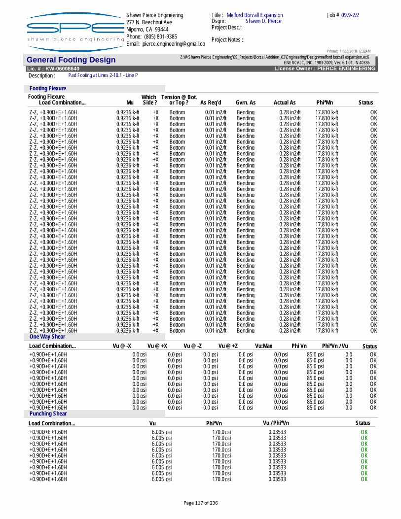
General Footing Design ENERCALC, INC. 1983-2009, Ver: 6.1.01, N:40336License Owner : PIERCE ENGINEERINGLic. # : KW-06008640
File: Z:\@Shawn Pierce Engineering\09_Projects\Borzal Addition_02\Engineering\Design\melford borzall expansion.ec6Printed: 1 FEB 2010, 6:32AM
Description : Pad Footing at Lines 2-10.1 - Line P
Shawn Pierce Engineering277 N. Beechnut AveNipomo, CA 93444Phone: (805) 801-9385Email: [email protected]
Title : Melford Borzall Expansion Job # 09.9-2/2
Project Desc.:Dsgnr: Shawn D. Pierce
Project Notes :
Footing FlexureAs Req'd
Footing FlexureTension @ Bot.Which
Actual As StatusMu Side ? or Top ? Gvrn. As Phi*MnLoad Combination...Z-Z, +0.90D+E+1.60H 0.9236 k-ft +X Bottom 0.01 in2/ft Bending 0.28 in2/ft 17.810 k-ft OKZ-Z, +0.90D+E+1.60H 0.9236 k-ft +X Bottom 0.01 in2/ft Bending 0.28 in2/ft 17.810 k-ft OKZ-Z, +0.90D+E+1.60H 0.9236 k-ft +X Bottom 0.01 in2/ft Bending 0.28 in2/ft 17.810 k-ft OKZ-Z, +0.90D+E+1.60H 0.9236 k-ft +X Bottom 0.01 in2/ft Bending 0.28 in2/ft 17.810 k-ft OKZ-Z, +0.90D+E+1.60H 0.9236 k-ft +X Bottom 0.01 in2/ft Bending 0.28 in2/ft 17.810 k-ft OKZ-Z, +0.90D+E+1.60H 0.9236 k-ft +X Bottom 0.01 in2/ft Bending 0.28 in2/ft 17.810 k-ft OKZ-Z, +0.90D+E+1.60H 0.9236 k-ft +X Bottom 0.01 in2/ft Bending 0.28 in2/ft 17.810 k-ft OKZ-Z, +0.90D+E+1.60H 0.9236 k-ft +X Bottom 0.01 in2/ft Bending 0.28 in2/ft 17.810 k-ft OKZ-Z, +0.90D+E+1.60H 0.9236 k-ft +X Bottom 0.01 in2/ft Bending 0.28 in2/ft 17.810 k-ft OKZ-Z, +0.90D+E+1.60H 0.9236 k-ft +X Bottom 0.01 in2/ft Bending 0.28 in2/ft 17.810 k-ft OKZ-Z, +0.90D+E+1.60H 0.9236 k-ft +X Bottom 0.01 in2/ft Bending 0.28 in2/ft 17.810 k-ft OKZ-Z, +0.90D+E+1.60H 0.9236 k-ft +X Bottom 0.01 in2/ft Bending 0.28 in2/ft 17.810 k-ft OKZ-Z, +0.90D+E+1.60H 0.9236 k-ft +X Bottom 0.01 in2/ft Bending 0.28 in2/ft 17.810 k-ft OKZ-Z, +0.90D+E+1.60H 0.9236 k-ft +X Bottom 0.01 in2/ft Bending 0.28 in2/ft 17.810 k-ft OKZ-Z, +0.90D+E+1.60H 0.9236 k-ft +X Bottom 0.01 in2/ft Bending 0.28 in2/ft 17.810 k-ft OKZ-Z, +0.90D+E+1.60H 0.9236 k-ft +X Bottom 0.01 in2/ft Bending 0.28 in2/ft 17.810 k-ft OKZ-Z, +0.90D+E+1.60H 0.9236 k-ft +X Bottom 0.01 in2/ft Bending 0.28 in2/ft 17.810 k-ft OKZ-Z, +0.90D+E+1.60H 0.9236 k-ft +X Bottom 0.01 in2/ft Bending 0.28 in2/ft 17.810 k-ft OKZ-Z, +0.90D+E+1.60H 0.9236 k-ft +X Bottom 0.01 in2/ft Bending 0.28 in2/ft 17.810 k-ft OKZ-Z, +0.90D+E+1.60H 0.9236 k-ft +X Bottom 0.01 in2/ft Bending 0.28 in2/ft 17.810 k-ft OKZ-Z, +0.90D+E+1.60H 0.9236 k-ft +X Bottom 0.01 in2/ft Bending 0.28 in2/ft 17.810 k-ft OKZ-Z, +0.90D+E+1.60H 0.9236 k-ft +X Bottom 0.01 in2/ft Bending 0.28 in2/ft 17.810 k-ft OKZ-Z, +0.90D+E+1.60H 0.9236 k-ft +X Bottom 0.01 in2/ft Bending 0.28 in2/ft 17.810 k-ft OKZ-Z, +0.90D+E+1.60H 0.9236 k-ft +X Bottom 0.01 in2/ft Bending 0.28 in2/ft 17.810 k-ft OKZ-Z, +0.90D+E+1.60H 0.9236 k-ft +X Bottom 0.01 in2/ft Bending 0.28 in2/ft 17.810 k-ft OKZ-Z, +0.90D+E+1.60H 0.9236 k-ft +X Bottom 0.01 in2/ft Bending 0.28 in2/ft 17.810 k-ft OKZ-Z, +0.90D+E+1.60H 0.9236 k-ft +X Bottom 0.01 in2/ft Bending 0.28 in2/ft 17.810 k-ft OKZ-Z, +0.90D+E+1.60H 0.9236 k-ft +X Bottom 0.01 in2/ft Bending 0.28 in2/ft 17.810 k-ft OKZ-Z, +0.90D+E+1.60H 0.9236 k-ft +X Bottom 0.01 in2/ft Bending 0.28 in2/ft 17.810 k-ft OKZ-Z, +0.90D+E+1.60H 0.9236 k-ft +X Bottom 0.01 in2/ft Bending 0.28 in2/ft 17.810 k-ft OKZ-Z, +0.90D+E+1.60H 0.9236 k-ft +X Bottom 0.01 in2/ft Bending 0.28 in2/ft 17.810 k-ft OKZ-Z, +0.90D+E+1.60H 0.9236 k-ft +X Bottom 0.01 in2/ft Bending 0.28 in2/ft 17.810 k-ft OKZ-Z, +0.90D+E+1.60H 0.9236 k-ft +X Bottom 0.01 in2/ft Bending 0.28 in2/ft 17.810 k-ft OKZ-Z, +0.90D+E+1.60H 0.9236 k-ft +X Bottom 0.01 in2/ft Bending 0.28 in2/ft 17.810 k-ft OKZ-Z, +0.90D+E+1.60H 0.9236 k-ft +X Bottom 0.01 in2/ft Bending 0.28 in2/ft 17.810 k-ft OKZ-Z, +0.90D+E+1.60H 0.9236 k-ft +X Bottom 0.01 in2/ft Bending 0.28 in2/ft 17.810 k-ft OKZ-Z, +0.90D+E+1.60H 0.9236 k-ft +X Bottom 0.01 in2/ft Bending 0.28 in2/ft 17.810 k-ft OKZ-Z, +0.90D+E+1.60H 0.9236 k-ft +X Bottom 0.01 in2/ft Bending 0.28 in2/ft 17.810 k-ft OKOne Way Shear
Vu @ +XLoad Combination... Vu @ -X Vu @ -Z Vu @ +Z Vu:Max Phi*Vn / VuPhi Vn Status+0.90D+E+1.60H 0.0 0.0 0.0 0.0 0.0 85.0 0.0psipsipsipsipsipsi OK+0.90D+E+1.60H 0.0 0.0 0.0 0.0 0.0 85.0 0.0psipsipsipsipsipsi OK+0.90D+E+1.60H 0.0 0.0 0.0 0.0 0.0 85.0 0.0psipsipsipsipsipsi OK+0.90D+E+1.60H 0.0 0.0 0.0 0.0 0.0 85.0 0.0psipsipsipsipsipsi OK+0.90D+E+1.60H 0.0 0.0 0.0 0.0 0.0 85.0 0.0psipsipsipsipsipsi OK+0.90D+E+1.60H 0.0 0.0 0.0 0.0 0.0 85.0 0.0psipsipsipsipsipsi OK+0.90D+E+1.60H 0.0 0.0 0.0 0.0 0.0 85.0 0.0psipsipsipsipsipsi OK+0.90D+E+1.60H 0.0 0.0 0.0 0.0 0.0 85.0 0.0psipsipsipsipsipsi OK+0.90D+E+1.60H 0.0 0.0 0.0 0.0 0.0 85.0 0.0psipsipsipsipsipsi OK+0.90D+E+1.60H 0.0 0.0 0.0 0.0 0.0 85.0 0.0psipsipsipsipsipsi OK
Vu / Phi*VnPunching Shear
StatusVu Phi*VnLoad Combination...+0.90D+E+1.60H 6.005 170.0 0.03533 OKpsipsi+0.90D+E+1.60H 6.005 170.0 0.03533 OKpsipsi+0.90D+E+1.60H 6.005 170.0 0.03533 OKpsipsi+0.90D+E+1.60H 6.005 170.0 0.03533 OKpsipsi+0.90D+E+1.60H 6.005 170.0 0.03533 OKpsipsi+0.90D+E+1.60H 6.005 170.0 0.03533 OKpsipsi+0.90D+E+1.60H 6.005 170.0 0.03533 OKpsipsi+0.90D+E+1.60H 6.005 170.0 0.03533 OKpsipsi+0.90D+E+1.60H 6.005 170.0 0.03533 OKpsipsi
Page 117 of 236

General Footing Design ENERCALC, INC. 1983-2009, Ver: 6.1.01, N:40336License Owner : PIERCE ENGINEERINGLic. # : KW-06008640
File: Z:\@Shawn Pierce Engineering\09_Projects\Borzal Addition_02\Engineering\Design\melford borzall expansion.ec6Printed: 1 FEB 2010, 6:32AM
Description : Pad Footing at Lines 2-10.1 - Line P
Shawn Pierce Engineering277 N. Beechnut AveNipomo, CA 93444Phone: (805) 801-9385Email: [email protected]
Title : Melford Borzall Expansion Job # 09.9-2/2
Project Desc.:Dsgnr: Shawn D. Pierce
Project Notes :
Vu / Phi*VnPunching Shear
StatusVu Phi*VnLoad Combination...+0.90D+E+1.60H 6.005 170.0 0.03533 OKpsipsi
Page 118 of 236
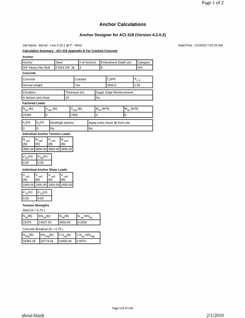
Anchor Calculations
Anchor Designer for ACI 318 (Version 4.2.0.2)
Job Name : Borzal - Line 2-10.1 @ P - Wind Date/Time : 2/1/2010 7:02:25 AM
Calculation Summary - ACI 318 Appendix D For Cracked Concrete
Anchor
Anchor Steel # of Anchors Embedment Depth (in) Category
3/4" Heavy Hex Bolt F1554 GR. 36 4 9 N/A
Concrete
Concrete Cracked f'c(psi) c,V
Normal weight Yes 2500.0 1.00
Condition Thickness (in) Suppl. Edge Reinforcement
A tension and shear 18 No
Factored Loads
Nua (lb) Vuax (lb) Vuay (lb) Mux (lb*ft) Muy (lb*ft)
15400 0 7600 0 0
ex(in) ey(in) Mod/high seismic Apply entire shear @ front row
0 0 No No
Individual Anchor Tension Loads
N ua1
(lb)
N ua2
(lb)
N ua3
(lb)
N ua4
(lb)
3850.00 3850.00 3850.00 3850.00
e'Nx(in) e'Ny(in)
0.00 0.00
Individual Anchor Shear Loads
V ua1
(lb)
V ua2
(lb)
V ua3
(lb)
V ua4
(lb)
1900.00 1900.00 1900.00 1900.00
e'Vx(in) e'Vy(in)
0.00 0.00
Tension Strengths
Steel ( = 0.75 )
Nsa(lb) Nsa(lb) Nua(lb) N ua /Nsa
19370 14527.50 3850.00 0.2650
Concrete Breakout ( = 0.75 )
Ncbg(lb) Ncbg(lb) Nua(lb) Nua /Ncbg
34365.39 25774.04 15400.00 0.5975
Page 1 of 2
2/1/2010about:blank
Page 119 of 236
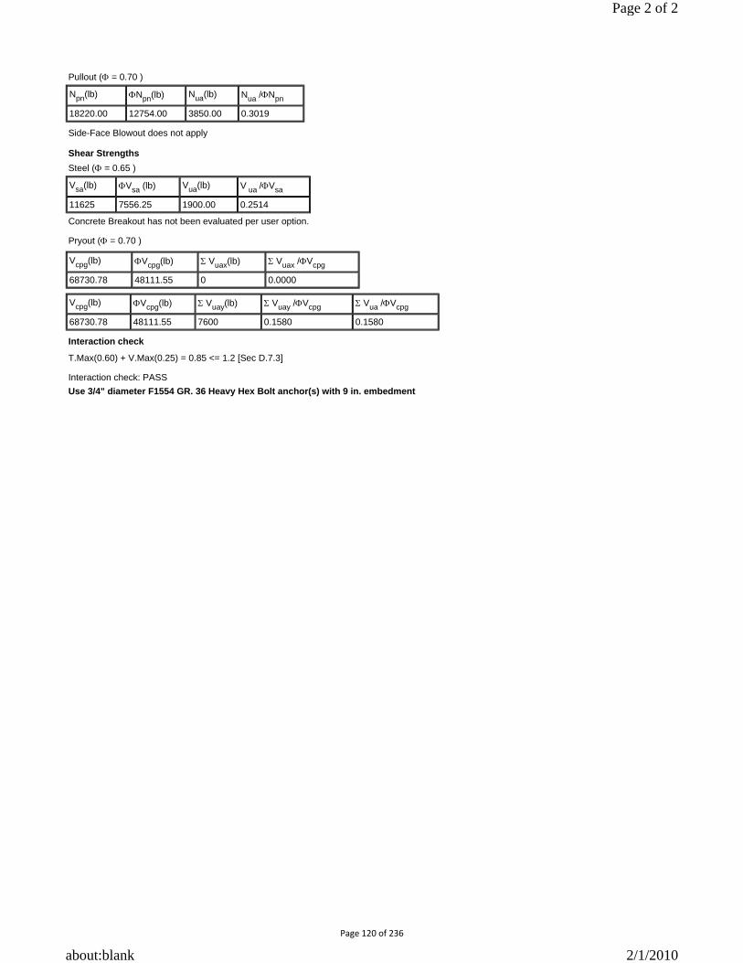
Pullout ( = 0.70 )
Npn(lb) Npn(lb) Nua(lb) Nua /Npn
18220.00 12754.00 3850.00 0.3019
Side-Face Blowout does not apply
Shear Strengths
Steel ( = 0.65 )
Vsa(lb) Vsa (lb) Vua(lb) V ua /Vsa
11625 7556.25 1900.00 0.2514
Concrete Breakout has not been evaluated per user option.
Pryout ( = 0.70 )
Vcpg(lb) Vcpg(lb) Vuax(lb) Vuax /Vcpg
68730.78 48111.55 0 0.0000
Vcpg(lb) Vcpg(lb) Vuay(lb) Vuay /Vcpg Vua /Vcpg
68730.78 48111.55 7600 0.1580 0.1580
Interaction check
T.Max(0.60) + V.Max(0.25) = 0.85 <= 1.2 [Sec D.7.3]
Interaction check: PASS
Use 3/4" diameter F1554 GR. 36 Heavy Hex Bolt anchor(s) with 9 in. embedment
Page 2 of 2
2/1/2010about:blank
Page 120 of 236

Anchor Calculations
Anchor Designer for ACI 318 (Version 4.2.0.2)
Job Name : Borzal - Line 2-10.1 @ P - Wind Date/Time : 2/1/2010 7:03:51 AM
Calculation Summary - ACI 318 Appendix D For Cracked Concrete
Anchor
Anchor Steel # of Anchors Embedment Depth (in) Category
3/4" Heavy Hex Bolt F1554 GR. 36 4 9 N/A
Concrete
Concrete Cracked f'c(psi) c,V
Normal weight Yes 2500.0 1.00
Condition Thickness (in) Suppl. Edge Reinforcement
A tension and shear 18 No
Factored Loads
Nua (lb) Vuax (lb) Vuay (lb) Mux (lb*ft) Muy (lb*ft)
-12000 0 -9000 0 0
ex(in) ey(in) Mod/high seismic Apply entire shear @ front row
0 0 No No
Individual Anchor Tension Loads
N
ua1
(lb)
N
ua2
(lb)
N
ua3
(lb)
N
ua4
(lb)
0.00 0.00 0.00 0.00
e'Nx(in) e'Ny(in)
0.00 0.00
Individual Anchor Shear Loads
V ua1
(lb)
V ua2
(lb)
V ua3
(lb)
V ua4
(lb)
2250.00 2250.00 2250.00 2250.00
e'Vx(in) e'Vy(in)
0.00 0.00
Tension Strengths
Steel ( = 0.75 )
Nsa(lb) Nsa(lb) Nua(lb) N ua /Nsa
19370 14527.50 0.00 0.0000
Concrete Breakout ( = 0.75 )
Ncbg(lb) Ncbg(lb) Nua(lb) Nua /Ncbg
34365.39 25774.04 0.00 0.0000
Page 1 of 2
2/1/2010about:blank
Page 121 of 236

Pullout ( = 0.70 )
Npn(lb) Npn(lb) Nua(lb) Nua /Npn
18220.00 12754.00 0.00 0.0000
Side-Face Blowout does not apply
Shear Strengths
Steel ( = 0.65 )
Vsa(lb) Vsa (lb) Vua(lb) V ua /Vsa
11625 7556.25 2250.00 0.2978
Concrete Breakout has not been evaluated per user option.
Pryout ( = 0.70 )
Vcpg(lb) Vcpg(lb) Vuax(lb) Vuax /Vcpg
68730.78 48111.55 0 0.0000
Vcpg(lb) Vcpg(lb) Vuay(lb) Vuay /Vcpg Vua /Vcpg
68730.78 48111.55 -9000 0.1871 0.1871
Interaction check
T.Max(0) <= 0.2 and V.Max(0.3) <= 1.0 [Sec D.7.2]
Interaction check: PASS
Use 3/4" diameter F1554 GR. 36 Heavy Hex Bolt anchor(s) with 9 in. embedment
Page 2 of 2
2/1/2010about:blank
Page 122 of 236
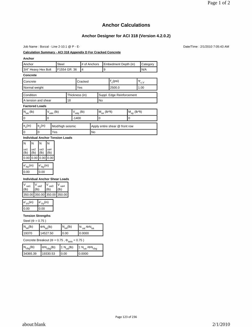
Anchor Calculations
Anchor Designer for ACI 318 (Version 4.2.0.2)
Job Name : Borzal - Line 2-10.1 @ P - E- Date/Time : 2/1/2010 7:05:43 AM
Calculation Summary - ACI 318 Appendix D For Cracked Concrete
Anchor
Anchor Steel # of Anchors Embedment Depth (in) Category
3/4" Heavy Hex Bolt F1554 GR. 36 4 9 N/A
Concrete
Concrete Cracked f'c(psi) c,V
Normal weight Yes 2500.0 1.00
Condition Thickness (in) Suppl. Edge Reinforcement
A tension and shear 18 No
Factored Loads
Nua (lb) Vuax (lb) Vuay (lb) Mux (lb*ft) Muy (lb*ft)
0 0 -1400 0 0
ex(in) ey(in) Mod/high seismic Apply entire shear @ front row
0 0 Yes No
Individual Anchor Tension Loads
N
ua1
(lb)
N
ua2
(lb)
N
ua3
(lb)
N
ua4
(lb)
0.00 0.00 0.00 0.00
e'Nx(in) e'Ny(in)
0.00 0.00
Individual Anchor Shear Loads
V ua1
(lb)
V ua2
(lb)
V ua3
(lb)
V ua4
(lb)
350.00 350.00 350.00 350.00
e'Vx(in) e'Vy(in)
0.00 0.00
Tension Strengths
Steel ( = 0.75 )
Nsa(lb) Nsa(lb) Nua(lb) N ua /Nsa
19370 14527.50 0.00 0.0000
Concrete Breakout ( = 0.75 , seis = 0.75 )
Ncbg(lb) Ncbg(lb) Nua(lb) Nua /Ncbg
34365.39 19330.53 0.00 0.0000
Page 1 of 2
2/1/2010about:blank
Page 123 of 236

Pullout ( = 0.70 , seis = 0.75 )
Npn(lb) Npn(lb) Nua(lb) Nua /Npn
18220.00 9565.50 0.00 0.0000
Side-Face Blowout does not apply
Shear Strengths
Steel ( = 0.65 )
Veq(lb) Veq(lb) Vua(lb) V ua /Veq
11625 7556.25 350.00 0.0463
Concrete Breakout has not been evaluated per user option.
Pryout ( = 0.70 , seis = 0.75 )
Vcpg(lb) Vcpg(lb) Vuax(lb) Vuax /Vcpg
68730.78 36083.66 0 0.0000
Vcpg(lb) Vcpg(lb) Vuay(lb) Vuay /Vcpg Vua /Vcpg
68730.78 36083.66 -1400 0.0388 0.0388
Interaction check
V.Max(0.05) <= 0.2 and T.Max(0) <= 1.0 [Sec D.7.1]
Interaction check: PASS
Use 3/4" diameter F1554 GR. 36 Heavy Hex Bolt anchor(s) with 9 in. embedment
Page 2 of 2
2/1/2010about:blank
Page 124 of 236

Page 125 of 236

Anchor Calculations
Anchor Designer for ACI 318 (Version 4.2.0.2)
Job Name : Borzal - Line 2-10.1 @ N (W) Date/Time : 2/4/2010 5:37:59 AM
Calculation Summary - ACI 318 Appendix D For Cracked Concrete
Anchor
Anchor Steel # of Anchors Embedment Depth (in) Category
4
Concrete
Concrete Cracked f'c(psi) c,V
Normal weight Yes NaN 1.00
Condition Thickness (in) Suppl. Edge Reinforcement
A tension and shear 18 No
Factored Loads
Nua (lb) Vuax (lb) Vuay (lb) Mux (lb*ft) Muy (lb*ft)
13700 6200 0 0 0
ex(in) ey(in) Mod/high seismic Apply entire shear @ front row
0 0 No No
Individual Anchor Tension Loads
N ua1
(lb)
N ua2
(lb)
N ua3
(lb)
N ua4
(lb)
3425.00 3425.00 3425.00 3425.00
e'Nx(in) e'Ny(in)
NaN NaN
Individual Anchor Shear Loads
V ua1
(lb)
V ua2
(lb)
V ua3
(lb)
V ua4
(lb)
1550.00 1550.00 1550.00 1550.00
e'Vx(in) e'Vy(in)
NaN NaN
Tension Strengths
Steel ( = NaN )
Nsa(lb) Nsa(lb) Nua(lb) N ua /Nsa
NaN 3425.00 NaN
Concrete Breakout ( = NaN )
Ncbg(lb) Ncbg(lb) Nua(lb) Nua /Ncbg
NaN NaN 13700.00 NaN
Page 1 of 2
2/4/2010about:blank
Page 126 of 236

Pullout does not apply
Side-Face Blowout ( = NaN )
Nsbg(lb) Nsbg(lb) Nua(lb) Nua /Nsbg
30542.82 22907.12 6850.00 0.2990
Shear Strengths
Steel ( = NaN )
Vsa(lb) Vsa (lb) Vua(lb) V ua /Vsa
NaN 1550.00 NaN
Concrete Breakout has not been evaluated per user option.
Pryout ( = NaN )
Vcpg(lb) Vcpg(lb) Vuax(lb) Vuax /Vcpg
NaN NaN 6200
Vcpg(lb) Vcpg(lb) Vuay(lb) Vuay /Vcpg Vua /Vcpg
NaN NaN 0 NaN
Interaction check
Interaction check:
Page 2 of 2
2/4/2010about:blank
Page 127 of 236

Anchor Calculations
Anchor Designer for ACI 318 (Version 4.2.0.2)
Job Name : Borzal - Line 2-10.1 @ N (W) Date/Time : 2/4/2010 5:40:01 AM
Calculation Summary - ACI 318 Appendix D For Cracked Concrete
Anchor
Anchor Steel # of Anchors Embedment Depth (in) Category
3/4" Heavy Hex Bolt F1554 GR. 36 4 12 N/A
Concrete
Concrete Cracked f'c(psi) c,V
Normal weight Yes 2500.0 1.00
Condition Thickness (in) Suppl. Edge Reinforcement
A tension and shear 18 No
Factored Loads
Nua (lb) Vuax (lb) Vuay (lb) Mux (lb*ft) Muy (lb*ft)
-15700 -5800 0 0 0
ex(in) ey(in) Mod/high seismic Apply entire shear @ front row
0 0 No No
Individual Anchor Tension Loads
N
ua1
(lb)
N
ua2
(lb)
N
ua3
(lb)
N
ua4
(lb)
0.00 0.00 0.00 0.00
e'Nx(in) e'Ny(in)
0.00 0.00
Individual Anchor Shear Loads
V ua1
(lb)
V ua2
(lb)
V ua3
(lb)
V ua4
(lb)
1450.00 1450.00 1450.00 1450.00
e'Vx(in) e'Vy(in)
0.00 0.00
Tension Strengths
Steel ( = 0.75 )
Nsa(lb) Nsa(lb) Nua(lb) N ua /Nsa
19370 14527.50 0.00 0.0000
Concrete Breakout ( = 0.75 )
Ncbg(lb) Ncbg(lb) Nua(lb) Nua /Ncbg
19446.45 14584.84 0.00 0.0000
Page 1 of 2
2/4/2010about:blank
Page 128 of 236

Pullout ( = 0.70 )
Npn(lb) Npn(lb) Nua(lb) Nua /Npn
18220.00 12754.00 0.00 0.0000
Side-Face Blowout ( = 0.75 )
Nsb(lb) Nsb(lb) Nua(lb) Nua /Nsb
0.00 0.00 0.00 N/A
Shear Strengths
Steel ( = 0.65 )
Vsa(lb) Vsa (lb) Vua(lb) V ua /Vsa
11625 7556.25 1450.00 0.1919
Concrete Breakout has not been evaluated per user option.
Pryout ( = 0.70 )
Vcpg(lb) Vcpg(lb) Vuax(lb) Vuax /Vcpg
38892.90 27225.03 -5800 0.2130
Vcpg(lb) Vcpg(lb) Vuay(lb) Vuay /Vcpg Vua /Vcpg
38892.90 27225.03 0 0.0000 0.2130
Interaction check
T.Max(0) <= 0.2 and V.Max(0.21) <= 1.0 [Sec D.7.2]
Interaction check: PASS
Use 3/4" diameter F1554 GR. 36 Heavy Hex Bolt anchor(s) with 12 in. embedment
Page 2 of 2
2/4/2010about:blank
Page 129 of 236

Page 130 of 236
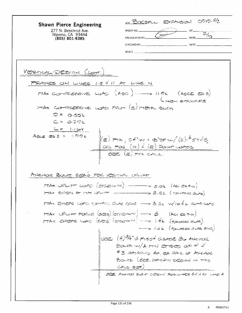
Page 131 of 236

b= 12 in h = 24 in d = in
Reinforcing Fy = psi
f'c = psi
ρ =
Mu = = lb-ft
Vu = = lbs
lbs (ASD) lbs (ASD) lbs (A
psf
ft
ft
lbs
wU = plf
lb-ft < lb-ft
lbs < lbs
PUp = lbs Strength Design
PUp U = lbs
plf
plf t = 4 in
plf
ft
ft
Standard Continuous Perimeter Footing - Vertical Loading
0.7 = MBNA Factor
0.00
L = L'/2 = 0.00
PDown/(Soil Bearing Pressure*b) =
12413
Check Actual Conditions
0.1PDown TL =
60000
Check Bending Capacity
(2) - #5 Top & Btm
2500
55683
20.69
0.0025
PDown DL = 0.1 PDown LL = 0.1
L' = Required Length =
Soil Bearing Pressure 2000
Check Uplift
7800
5460
0.31
PDown U/L' = 6200
1E-06MU = wUL2/3 =
VU = wUL = 0.155
55683
12413
PDown U = 1.4*(DL + CLL) + 1.7(LL) =
PUp*.7 =
Determine Dead Load Resistance
Footing:
Slab:
150pcf*b*h =
150pcf*t*4' =
300
200
wU DL = 1.4*(Ftg + Slab) = 700
Req'd L = PUp U/wU DL = 7.8
ft
VU/wU DL = 17.73Max L Shear =
Max L Moment = 15.45
c
yy
f
ffbd
'7.11
12
9.0 2
2
'2 bdf c
UDL
U
w
M 3*
Page 132 of 236

b= 12 in h = 24 in d = in
Reinforcing Fy = psi
f'c = psi
ρ =
Mu = = lb-ft
Vu = = lbs
psf
plf
ft
= ft
lbs
lbs t = 4 in
lbs
lbs
19574
ASD Thrust Resistance = (Total Thrust)/1.7 = 11514
CONTROLS
Total Passive Resistance = LMax*All Ult Pass Press = 7574
Slab Tension = t*3t*5*√f'c = 12000
14.89
Total Thrust Resistance =
10.82LMax Mnt =
Passive Pressure = 350
Allowed Ultimate Passive Pressure = 700
LMax Shear = Vu/Allowed Ult Passive Press =
23221
10425
Check Passive Resistance
2500
0.0030
8.688
(2) - #5 Top & Btm 60000
Standard Continuous Perimeter Footing - Thrust Loading
Check Bending Capacity
c
yy
f
ffhd
'7.11
12
9.0 2
2
'2 hdf c
Passive
U
w
M
*7.1
3*2*
Page 133 of 236

4 in Slab
lbs
= lbs
f'c = psi W at end of hairpin 10 ft
Assume no Hairpin
10 in
= lbs
lbs
lbs
2
2500
3200
CSlab design = Cslab/Factor of Safety =
Factor of Safety =
12500
Vthrust Inward
CSlab = 0.25f'cbd =
bPlate =
Check Concrete Tensile Failure at end of Base plate:
Check Concrete Compressive Failure at face of base plate:
Adjacent Slab will brace for buckling
25000
(1) - #3 Hairpin
38400
CONTROLSTension of Steel = 0.9(Ab)fy =
Check Concrete Tensile Failure at end of Hairpin:
7920
Check Thrust
Concrete Resistance for
Vthrust Outward
Check Rebar:
bdfT cSlab '6.1
bdfT cSlab '6.1
Page 134 of 236

FOUNDATION ANALYSIS
Office Expansion
Page 135 of 236

Page 136 of 236
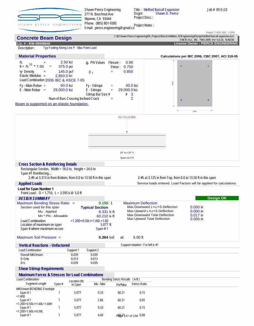
Concrete Beam Design ENERCALC, INC. 1983-2009, Ver: 6.0.24, N:40336License Owner : PIERCE ENGINEERINGLic. # : KW-06008640
File: Z:\@Shawn Pierce Engineering\09_Projects\Borzal Addition_02\Engineering\Design\melford borzall expansion.ec6Printed: 17 NOV 2009, 1:52PM
Description : Typ Footing Aloing Line P - Max Point Load
Shawn Pierce Engineering277 N. Beechnut AveNipomo, CA 93444Phone: (805) 801-9385Email: [email protected]
Title : Melford Borzall Expansion Job # 09.9-2/2
Project Desc.:Dsgnr: Shawn D. Pierce
Project Notes :
Material Properties Calculations per IBC 2006, CBC 2007, ACI 318-05
2.507.50
145.0Elastic Modulus 2,850.0 ksi
1
=60.0
29,000.040.0
29,000.03
Beam is supported on an elastic foundation,
2
= 0.900.750
f'c ksi
Fy - Main Rebar ksi
Density
1/2
=
fr = f'c * 375.0pcf
E - Main Rebar ksi
psi
=
Fy - Stirrups ksi
===
E - Stirrups ksi
18 in
24
in
0.850
===
Shear :
Stirrup Bar Size #Num of Bars Crossing Inclined Crack
Phi Values Flexure :
#
Load Combination :2006 IBC & ASCE 7-05
18" w x 24" h
Span=10.0 ft
D(1.71) L(3.595)
.Cross Section & Reinforcing DetailsRectangular Section, Width = 18.0 in, Height = 24.0 inSpan #1 Reinforcing.... 2-#5 at 3.313 in from Bottom, from 0.0 to 13.50 ft in this span 2-#5 at 3.125 in from Top, from 0.0 to 13.50 ft in this span
.Service loads entered. Load Factors will be applied for calculations.Applied LoadsLoad for Span Number 1
Point Load : D = 1.710, L = 3.595 k @ 5.0 ft.Design OKDESIGN SUMMARY
Maximum Bending Stress Ratio = 0.155 : 1
Load Combination +1.20D+0.50Lr+1.60L+1.60
Span # where maximum occurs Span # 1
Maximum Soil Pressure = 0.364 ksf at 5.00 ft
Location of maximum on span 5.077 ft
Mn * Phi : Allowable 60.210 k-ft
Typical SectionSection used for this spanMu : Applied 9.331 k-ft
Maximum DeflectionMax Downward L+Lr+S Deflection 0.000 inMax Upward L+Lr+S Deflection 0.000 inMax Downward Total Deflection 0.017 inMax Upward Total Deflection 0.005 in
.Load Combination Support 1 Support 2Vertical Reactions - Unfactored Support notation : Far left is #1
Overall MAXimum 0.039 0.039D Only 0.013 0.013D+L 0.039 0.039
.Shear Stirrup Requirements
.Maximum Forces & Stresses for Load Combinations
Span #Bending Stress Results ( k-ft )Location (ft)Load Combination
Mu : Max Stress RatioSegment Length Phi*Mnxin SpanMAXimum BENDING Envelope Span # 1 1 5.077 9.33 60.21 0.15+1.40D Span # 1 1 5.077 2.86 60.21 0.05+1.20D+0.50Lr+1.60L+1.60H Span # 1 1 5.077 9.33 60.21 0.15+1.20D+1.60Lr+0.50L Span # 1 1 5.077 4.60 60.21 0.08
.Page 137 of 236

FOUNDATION ANALYSIS
Conference Room Expansion
Page 138 of 236

Page 139 of 236

Concrete Beam Design ENERCALC, INC. 1983-2009, Ver: 6.0.24, N:40336License Owner : PIERCE ENGINEERINGLic. # : KW-06008640
File: Z:\@Shawn Pierce Engineering\09_Projects\Borzal Addition_02\Engineering\Design\melford borzall expansion.ec6Printed: 17 NOV 2009, 1:53PM
Description : (E) Footing for Additional Point Load - Intersection of Lines 2.5 & D.5
Shawn Pierce Engineering277 N. Beechnut AveNipomo, CA 93444Phone: (805) 801-9385Email: [email protected]
Title : Melford Borzall Expansion Job # 09.9-2/2
Project Desc.:Dsgnr: Shawn D. Pierce
Project Notes :
Material Properties Calculations per IBC 2006, CBC 2007, ACI 318-05
2.507.50
145.0Elastic Modulus 2,850.0 ksi
1
=60.0
29,000.040.0
29,000.03
Beam is supported on an elastic foundation,
2
= 0.900.750
f'c ksi
Fy - Main Rebar ksi
Density
1/2
=
fr = f'c * 375.0pcf
E - Main Rebar ksi
psi
=
Fy - Stirrups ksi
===
E - Stirrups ksi
12 in
18
in
0.850
===
Shear :
Stirrup Bar Size #Num of Bars Crossing Inclined Crack
Phi Values Flexure :
#
Load Combination :2006 IBC & ASCE 7-05
12" w x 18" h
Span=10.0 ft
D(0.16) Lr(1.125)
D(0.13) Lr(0.1)D(0.305) Lr(0.565)
.Cross Section & Reinforcing DetailsRectangular Section, Width = 12.0 in, Height = 18.0 inSpan #1 Reinforcing.... 1-#5 at 3.313 in from Bottom, from 0.0 to 15.0 ft in this span 1-#5 at 3.313 in from Top, from 0.0 to 15.0 ft in this span
.Service loads entered. Load Factors will be applied for calculations.Applied LoadsBeam self weight calculated and added to loadsLoad for Span Number 1
Point Load : D = 0.160, Lr = 1.125 k @ 5.0 ftUniform Load : D = 0.130, Lr = 0.10 k/ft, Extent = 0.0 -->> 5.0 ft, Tributary Width = 1.0 ftUniform Load : D = 0.3050, Lr = 0.5650 k/ft, Extent = 5.0 -->> 10.0 ft, Tributary Width = 1.0 ft
.Design OKDESIGN SUMMARYMaximum Bending Stress Ratio = 0.103 : 1
Load Combination +1.20D+1.60Lr+0.50L
Span # where maximum occurs Span # 1
Maximum Soil Pressure = 1.361 ksf at 10.00 ft
Location of maximum on span 5.077 ft
Mn * Phi : Allowable 23.075 k-ft
Typical SectionSection used for this spanMu : Applied 2.384 k-ft
Maximum DeflectionMax Downward L+Lr+S Deflection 0.000 inMax Upward L+Lr+S Deflection 0.000 inMax Downward Total Deflection 0.063 inMax Upward Total Deflection 0.015 in
.Load Combination Support 1 Support 2Vertical Reactions - Unfactored Support notation : Far left is #1
Overall MAXimum 0.031 0.105D Only 0.025 0.045D+Lr 0.031 0.105
.Shear Stirrup Requirements
.Maximum Forces & Stresses for Load Combinations
Span #Bending Stress Results ( k-ft )Location (ft)Load Combination
Mu : Max Stress RatioSegment Length Phi*Mnxin SpanMAXimum BENDING Envelope Span # 1 1 5.077 2.38 23.07 0.10+1.40D Span # 1 1 5.385 0.28 23.07 0.01+1.20D+0.50Lr+1.60L+1.60H Span # 1 1 5.077 0.91 23.07 0.04
Page 140 of 236

Concrete Beam Design ENERCALC, INC. 1983-2009, Ver: 6.0.24, N:40336License Owner : PIERCE ENGINEERINGLic. # : KW-06008640
File: Z:\@Shawn Pierce Engineering\09_Projects\Borzal Addition_02\Engineering\Design\melford borzall expansion.ec6Printed: 17 NOV 2009, 1:53PM
Description : (E) Footing for Additional Point Load - Intersection of Lines 2.5 & D.5
Shawn Pierce Engineering277 N. Beechnut AveNipomo, CA 93444Phone: (805) 801-9385Email: [email protected]
Title : Melford Borzall Expansion Job # 09.9-2/2
Project Desc.:Dsgnr: Shawn D. Pierce
Project Notes :
Span #Bending Stress Results ( k-ft )Location (ft)Load Combination
Mu : Max Stress RatioSegment Length Phi*Mnxin Span+1.20D+1.60Lr+0.50L Span # 1 1 5.077 2.38 23.07 0.10
.Location in SpanLoad CombinationMax. "-" Defl Location in SpanLoad Combination Span Max. "+" Defl
Overall Maximum Deflections - Unfactored Loads
Span 1 1 0.0630 10.000 0.0000 0.000
Page 141 of 236
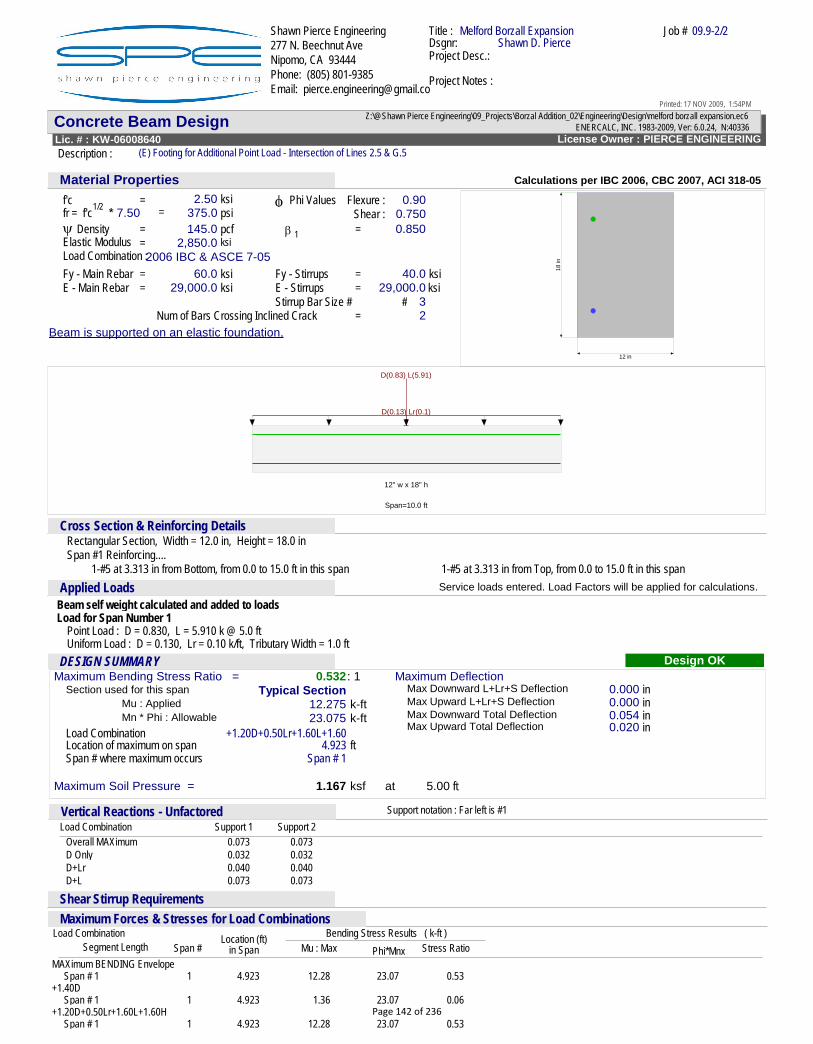
Concrete Beam Design ENERCALC, INC. 1983-2009, Ver: 6.0.24, N:40336License Owner : PIERCE ENGINEERINGLic. # : KW-06008640
File: Z:\@Shawn Pierce Engineering\09_Projects\Borzal Addition_02\Engineering\Design\melford borzall expansion.ec6Printed: 17 NOV 2009, 1:54PM
Description : (E) Footing for Additional Point Load - Intersection of Lines 2.5 & G.5
Shawn Pierce Engineering277 N. Beechnut AveNipomo, CA 93444Phone: (805) 801-9385Email: [email protected]
Title : Melford Borzall Expansion Job # 09.9-2/2
Project Desc.:Dsgnr: Shawn D. Pierce
Project Notes :
Material Properties Calculations per IBC 2006, CBC 2007, ACI 318-05
2.507.50
145.0Elastic Modulus 2,850.0 ksi
1
=60.0
29,000.040.0
29,000.03
Beam is supported on an elastic foundation,
2
= 0.900.750
f'c ksi
Fy - Main Rebar ksi
Density
1/2
=
fr = f'c * 375.0pcf
E - Main Rebar ksi
psi
=
Fy - Stirrups ksi
===
E - Stirrups ksi
12 in
18
in
0.850
===
Shear :
Stirrup Bar Size #Num of Bars Crossing Inclined Crack
Phi Values Flexure :
#
Load Combination :2006 IBC & ASCE 7-05
12" w x 18" h
Span=10.0 ft
D(0.83) L(5.91)
D(0.13) Lr(0.1)
.Cross Section & Reinforcing DetailsRectangular Section, Width = 12.0 in, Height = 18.0 inSpan #1 Reinforcing.... 1-#5 at 3.313 in from Bottom, from 0.0 to 15.0 ft in this span 1-#5 at 3.313 in from Top, from 0.0 to 15.0 ft in this span
.Service loads entered. Load Factors will be applied for calculations.Applied LoadsBeam self weight calculated and added to loadsLoad for Span Number 1
Point Load : D = 0.830, L = 5.910 k @ 5.0 ftUniform Load : D = 0.130, Lr = 0.10 k/ft, Tributary Width = 1.0 ft
.Design OKDESIGN SUMMARYMaximum Bending Stress Ratio = 0.532 : 1
Load Combination +1.20D+0.50Lr+1.60L+1.60
Span # where maximum occurs Span # 1
Maximum Soil Pressure = 1.167 ksf at 5.00 ft
Location of maximum on span 4.923 ft
Mn * Phi : Allowable 23.075 k-ft
Typical SectionSection used for this spanMu : Applied 12.275 k-ft
Maximum DeflectionMax Downward L+Lr+S Deflection 0.000 inMax Upward L+Lr+S Deflection 0.000 inMax Downward Total Deflection 0.054 inMax Upward Total Deflection 0.020 in
.Load Combination Support 1 Support 2Vertical Reactions - Unfactored Support notation : Far left is #1
Overall MAXimum 0.073 0.073D Only 0.032 0.032D+Lr 0.040 0.040D+L 0.073 0.073
.Shear Stirrup Requirements
.Maximum Forces & Stresses for Load Combinations
Span #Bending Stress Results ( k-ft )Location (ft)Load Combination
Mu : Max Stress RatioSegment Length Phi*Mnxin SpanMAXimum BENDING Envelope Span # 1 1 4.923 12.28 23.07 0.53+1.40D Span # 1 1 4.923 1.36 23.07 0.06+1.20D+0.50Lr+1.60L+1.60H Span # 1 1 4.923 12.28 23.07 0.53
Page 142 of 236

Concrete Beam Design ENERCALC, INC. 1983-2009, Ver: 6.0.24, N:40336License Owner : PIERCE ENGINEERINGLic. # : KW-06008640
File: Z:\@Shawn Pierce Engineering\09_Projects\Borzal Addition_02\Engineering\Design\melford borzall expansion.ec6Printed: 17 NOV 2009, 1:54PM
Description : (E) Footing for Additional Point Load - Intersection of Lines 2.5 & G.5
Shawn Pierce Engineering277 N. Beechnut AveNipomo, CA 93444Phone: (805) 801-9385Email: [email protected]
Title : Melford Borzall Expansion Job # 09.9-2/2
Project Desc.:Dsgnr: Shawn D. Pierce
Project Notes :
Span #Bending Stress Results ( k-ft )Location (ft)Load Combination
Mu : Max Stress RatioSegment Length Phi*Mnxin Span+1.20D+1.60Lr+0.50L Span # 1 1 4.923 4.64 23.07 0.20
.Location in SpanLoad CombinationMax. "-" Defl Location in SpanLoad Combination Span Max. "+" Defl
Overall Maximum Deflections - Unfactored Loads
Span 1 1 0.0540 5.000 0.0000 0.000
Page 143 of 236

Concrete Beam Design ENERCALC, INC. 1983-2009, Ver: 6.0.24, N:40336License Owner : PIERCE ENGINEERINGLic. # : KW-06008640
File: Z:\@Shawn Pierce Engineering\09_Projects\Borzal Addition_02\Engineering\Design\melford borzall expansion.ec6Printed: 17 NOV 2009, 2:06PM
Description : Continuous footing under new column
Shawn Pierce Engineering277 N. Beechnut AveNipomo, CA 93444Phone: (805) 801-9385Email: [email protected]
Title : Melford Borzall Expansion Job # 09.9-2/2
Project Desc.:Dsgnr: Shawn D. Pierce
Project Notes :
Material Properties Calculations per IBC 2006, CBC 2007, ACI 318-05
2.507.50
145.0Elastic Modulus 2,850.0 ksi
1
=60.0
29,000.040.0
29,000.03
Beam is supported on an elastic foundation,
2
= 0.900.750
f'c ksi
Fy - Main Rebar ksi
Density
1/2
=
fr = f'c * 375.0pcf
E - Main Rebar ksi
psi
=
Fy - Stirrups ksi
===
E - Stirrups ksi
18 in
24
in
0.850
===
Shear :
Stirrup Bar Size #Num of Bars Crossing Inclined Crack
Phi Values Flexure :
#
Load Combination :2006 IBC & ASCE 7-05
18" w x 24" h
Span=13.50 ft
D(2.92) L(7.035)
.Cross Section & Reinforcing DetailsRectangular Section, Width = 18.0 in, Height = 24.0 inSpan #1 Reinforcing.... 2-#5 at 3.313 in from Bottom, from 0.0 to 13.50 ft in this span 2-#5 at 3.125 in from Top, from 0.0 to 13.50 ft in this span
.Service loads entered. Load Factors will be applied for calculations.Applied LoadsLoad for Span Number 1
Point Load : D = 2.920, L = 7.035 k @ 10.50 ft.Design OKDESIGN SUMMARY
Maximum Bending Stress Ratio = 0.216 : 1
Load Combination +1.20D+0.50Lr+1.60L+1.60
Span # where maximum occurs Span # 1
Maximum Soil Pressure = 1.455 ksf at 13.50 ft
Location of maximum on span 10.488 ft
Mn * Phi : Allowable 60.210 k-ft
Typical SectionSection used for this spanMu : Applied 12.985 k-ft
Maximum DeflectionMax Downward L+Lr+S Deflection 0.000 inMax Upward L+Lr+S Deflection 0.000 inMax Downward Total Deflection 0.067 inMax Upward Total Deflection -0.035 in
.Load Combination Support 1 Support 2Vertical Reactions - Unfactored Support notation : Far left is #1
Overall MAXimum -0.001 0.227D Only -0.000 0.066D+L -0.001 0.227
.Shear Stirrup Requirements
.Maximum Forces & Stresses for Load Combinations
Span #Bending Stress Results ( k-ft )Location (ft)Load Combination
Mu : Max Stress RatioSegment Length Phi*Mnxin SpanMAXimum BENDING Envelope Span # 1 1 10.488 12.98 60.21 0.22+1.40D Span # 1 1 10.488 3.60 60.21 0.06+1.20D+0.50Lr+1.60L+1.60H Span # 1 1 10.488 12.98 60.21 0.22+1.20D+1.60Lr+0.50L Span # 1 1 10.488 6.18 60.21 0.10
.Page 144 of 236

LATERAL ANALYSIS
Page 145 of 236

Melford Borzall Expansion Project Number: 09.9-2/2
Latitude: 34°54'40.29" or 34.91° Longitude: -120°27'21.55" or -120.46° Conterminous 48 States 2003 NEHRP Seismic Design Provisions Latitude = 34.91 Longitude = -120.46 Spectral Response Accelerations Ss and S1 Ss and S1 = Mapped Spectral Acceleration Values Site Class B - Fa = 1.0 ,Fv = 1.0 Data are based on a 0.009999999776482582 deg grid spacing Period Sa (sec) (g) 0.2 1.266 (Ss, Site Class B) 1.0 0.434 (S1, Site Class B)
Conterminous 48 States 2003 NEHRP Seismic Design Provisions Latitude = 34.91 Longitude = -120.46 Spectral Response Accelerations SMs and SM1 SMs = Fa x Ss and SM1 = Fv x S1 Site Class D - Fa = 1.0 ,Fv = 1.566 Period Sa (sec) (g) 0.2 1.266 (SMs, Site Class D) 1.0 0.680 (SM1, Site Class D)
Conterminous 48 States 2003 NEHRP Seismic Design Provisions Latitude = 34.91 Longitude = -120.46 Design Spectral Response Accelerations SDs and SD1 SDs = 2/3 x SMs and SD1 = 2/3 x SM1 Site Class D - Fa = 1.0 ,Fv = 1.566 Period Sa (sec) (g) 0.2 0.844 (SDs, Site Class D) 1.0 0.453 (SD1, Site Class D)
Page 146 of 236

ASCE 7-05 Seismic Factor Determination ENERCALC, INC. 1983-2008, Ver: 6.0.221, N:40336License Owner : PIERCE ENGINEERINGLic. # : KW-06008640
File: Z:\@Shawn Pierce Engineering\09_Projects\Borzal Addition_02\Engineering\Design\melford borzall expansion.ec6Printed: 16 NOV 2009, 4:38PM
Description : Melford Borzall Expansion
Title Block Line 1You can changes this areausing the "Settings" menu itemand then using the "Printing &Title Block" selection.Title Block Line 6
Title : Melford Borzall Expansion Job # 09.9-2/2
Project Desc.:Dsgnr: Shawn D. Pierce
Project Notes :
Occupancy CategoryACSE 7-05, Page 3, Table 1-1
Calculations per IBC 2006 & ASCE 7-05
"II" : All Buildings and other structures except those listed as Category I, III, and IVOccupancy Category of Building or Other Structure :
Occupancy Importance Factor = 1 ACSE 7-05, Page 116, Table 11.5-1
ASCE 7-05 9.4.1.1USER DEFINED Ground MotionMax. Ground Motions, 5% Damping :
S = 1.266S g, 0.2 sec responseS 0.43401 g, 1.0 sec response=
Site Classification ASCE 7-05 Table 20.3-1"D" : Shear Wave Velocity 600 to 1,200 ft/sec = DSite Coefficients Fa & Fv ASCE 7-05 Table 11.4-1 & 11.4-2
(using straight-line interpolation from table values)Fa = 1.00Fv = 1.57
Maximum Considered Eartquake Acceleration ASCE 7-05 Table 11.4-3S = Fa * Ss 1.266=MSS = Fv * S1 = 0.680M1
Design Spectral Acceleration ASCE 7-05 Table 11.4-4S = S * 2/3 = 0.844MSDS= 0.453S = S * 2/3M1D1
Seismic Design Category ASCE 7-05 Table 11.6-1= D ( SD1 is most severe )
Site Class, Site Coeff. and Design Category
ASCE 7-05 Table 12.2-1
Basic Seismic Force Resisting System . . . Bearing Wall SystemsLight-framed walls sheathed w/wood structural panels rated for shear resistance or steel sheets.
NOTE! See ASCE 7-05 for all applicable footnotes.
Building height Limits :Response Modification Coefficient " R " = 6.50Category "A & B" Limit: No LimitSystem Overstrength Factor " Wo " = 3.00Category "C" Limit: No LimitDeflection Amplification Factor " Cd " = 4.00 Category "D" Limit: Limit = 65Category "E" Limit: Limit = 65Category "F" Limit: Limit = 65
Resisting System
Redundancy FactorRedundancy Factor ASCE 7-05 Section 12.3.4
Seismic Design Category of D, E, or F therefore Redundancy Factor " p " = 1.3
Lateral Force Procedure ASCE 7-05 Section 12.8
Equivalent Lateral Force ProcedureThe "Equivalent Lateral Force Procedure" is being used according to the provisions of ASCE 7-05 12.8
Use ASCE 12.8-7Determine Building PeriodStructure Type for Building Period Calculation : All Other Structural Systems
" Ct " value 0.020=" x " value
" hn " : Height from base to highest level = 12.330 ft
" Ta " Approximate fundemental period using Eq. 12.8-7 :12.000"TL" : Long-period transition period per ASCE 7-05 Maps 22-15 -> 22-20 sec
Ta = Ct * (hn ^ x) = 0.132 0.75
sec=
Building Period " Ta " Calculated from Approximate Method selected = 0.132 sec
" Cs " Response Coefficient ASCE 7-05 Section 12.8.1.1S : Short Period Design Spectral Response 0.844" R " : Response Modification Factor 6.50" I " : Occupancy Importance Factor = 1
0.130From Eq. 12.8-2, Preliminary Cs = 0.530From Eq. 12.8-3 & 12.8-4 , Cs need not exceed =
From Eq. 12.8-5 & 12.8-6, Cs not be less than = 0.010
DS
=Cs : Seismic Response Coefficient = S / (R/I) * 0.70 0.0909DSUser has selected ASCE 12.8.1.3 : Regular structure,Less than 5 Stories and with T <<= 0.5 sec, SO Ss <= 1.5 for Cs calculation
= =
Page 147 of 236

ASCE 7-05 Seismic Factor Determination ENERCALC, INC. 1983-2008, Ver: 6.0.221, N:40336License Owner : PIERCE ENGINEERINGLic. # : KW-06008640
File: Z:\@Shawn Pierce Engineering\09_Projects\Borzal Addition_02\Engineering\Design\melford borzall expansion.ec6Printed: 16 NOV 2009, 4:38PM
Description : Melford Borzall Expansion
Title Block Line 1You can changes this areausing the "Settings" menu itemand then using the "Printing &Title Block" selection.Title Block Line 6
Title : Melford Borzall Expansion Job # 09.9-2/2
Project Desc.:Dsgnr: Shawn D. Pierce
Project Notes :
Seismic Base Shear ASCE 7-05 Section 12.8.3
W ( see Sum Wi below ) = 0.00 k
Calculated for Allowable Stress Design Load Combinations
Cs = 0.0909 from 12.8.1.1Seismic Base Shear V = Cs * W = 0.00 kVertical Distribution of Seismic Forces
" k " : hx exponent based on Ta = 1.00Table of building Weights by Floor Level...
Wi : Weight Hi : Height (Wi * Hi) ^k Cvx Fx=Cvx * V Sum Story Shear Sum Story MomentLevel #
Sum Wi = 0.00 k Total Base Shear = 0.00 kBase Moment =
0.00 k-ftSum Wi * Hi = 0.0 k-ft
Diaphragm Forces : Seismic Design Category "D", "E" & "F" ASCE 7-05 9.5.2.6.4.4
Level # Wi Fi Sum Fi Sum Wi FpxWpx . . . . . . . . . . . . . . . . . . . . . . . . . . . . . .Weight at level of diaphragm and other structure elements attached to it.Fi . . . . . . . . . . . . . . . . . . . . . . . . . . . . . .Design Lateral Force applied at the level.Sum Fi . . . . . . . . . . . . . . . . . . . . . . . . . . . . .Sum of "Lat. Force" of current level plus all levels above
0.20 * S * I * WpxMIN Req'd Force @ Level . . . . . . . . . . DS
DSMAX Req'd Force @ Level . . . . . . . . . .0.40 * S * I * WpxFpx : Design Force @ Level . . . . . . . . . .Wpx * SUM(x->n) Fi / SUM(x->n) wi, x = Current level, n = Top Level
Wall AnchorageConcrete & Masonry Wall Normal Force : Minimum Force per ACSE 7-05 12.11.1
Minimum Factor : 0.40 * SDS * Importance * Weight 0.3376 * Weight=
Concrete & Masonry Wall Anchorage : Seismic Design Category "C" & "D" per ACSE 7-05 12.11.2.1
Actual Wall Weight Tributary to Anchor lbs/ lin. ft
Rigid Diaphragm Design Force = 0.40 * SDS * I * Trib. Weight =
=
lbs / foot
lbs / footFlexible Diaphragm Design Force = 0.80 * SDS * I * Trib. Weight =
0.00
0.00
Fp : Anchorage Design Force . . .
Combination of Load Effects ASCE 7-05 12.4.2.3
0.000 0.000 0.000 0.000 0.000 0.000 0.000 0.000 0.000E = p * Qe + 0.20 * SDS * D = 0.000 0.000 0.000E = p * Qe + 0.20 * SDS * D = 0.000 0.000 0.000E = p * Qe + 0.20 * SDS * D = 0.000 0.000 E = p * Qe + 0.20 * SDS * D = 0.000 0.000 0.000 E = p * Qe + 0.20 * SDS * D = 0.000 0.000 0.000 0.000E = p * Qe + 0.20 * SDS * D =
Load DescriptionD
Dead LoadQe E
Seismic Load H & V Load EffectE = p * Qe + 0.20 * SDS * D =E = p * Qe + 0.20 * SDS * D =
Page 148 of 236

LATERAL ANALYSIS
Office Expansion
Page 149 of 236

Page 150 of 236

Page 151 of 236

Page 152 of 236

Page 153 of 236

Anchor Calculations
Anchor Designer for ACI 318 (Version 4.2.0.2)
Job Name : Holdown into (E) Footing - Line N Date/Time : 2/5/2010 8:00:04 AM
Calculation Summary - ACI 318 Appendix D For Cracked Concrete
Anchor
Anchor Steel # of Anchors Embedment Depth (in) Category
5/8" SET-XP A307 GR. C 1 5 1
Concrete
Concrete Cracked f'c(psi) c,V
Normal weight Yes 2500.0 1.00
Condition Thickness (in) Suppl. Edge Reinforcement
B tension and shear 18 No
Hole Condition Inspection Temp. Range
Dry Concrete Continuous 1
Factored Loads
Nua (lb) Vuax (lb) Vuay (lb) Mux (lb*ft) Muy (lb*ft)
1740 0 0 0 0
ex(in)
ey(in)
Mod/high seismic
Anchor w/ sustained tension
Anchor only resists wind/seis loads
Apply entire shear @ front row
0 0 Yes No Yes No
Individual Anchor Tension Loads
N ua1 (lb)
1740.00
e'Nx(in) e'Ny(in)
0.00 0.00
Individual Anchor Shear Loads
V ua1 (lb)
0.00
e'Vx(in) e'Vy(in)
0.00 0.00
Tension Strengths
Steel ( = 0.75 )
Nsa(lb) Nsa(lb) Nua(lb) N ua /Nsa
13110 9832.50 1740.00 0.1770
Concrete Breakout ( = 0.65 , seis = 0.75 )
Ncb(lb) Ncb(lb) Nua(lb) Nua /Ncb
5854.03 2853.84 1740.00 0.6097
Page 1 of 2
2/5/2010about:blank
Page 154 of 236

Adhesive ( = 0.65 , seis = 0.75 )
Na(lb) Na(lb) Nua(lb) Nua /Na
4342.15 2116.80 1740.00 0.8220
Side-Face Blowout does not apply
Shear Strengths
Steel ( = 0.65 , v.seis = 0.71 )
Veq(lb) Veq(lb) Vua(lb) V ua /Veq
5584.15 3629.70 0.00 0.0000
Concrete Breakout (case 1) ( = 0.70 , seis = 0.75 )
Vcbx(lb) Vcbx(lb) Vuax(lb) Vuax /Vcbx
2746.17 1441.74 0.00 0.0000
Vcby(lb) Vcby(lb) Vuay(lb) Vuay /Vcby Vua /Vcb
8181.50 4295.29 0.00 0.0000 0.0000
Concrete Breakout (case 2) does not apply to single anchor layout
Concrete Breakout (case 3) ( = 0.70 , seis = 0.75 )
cx1 edge
Vcby(lb) Vcby(lb) Vuay(lb) Vuay /Vcby
40262.18 21137.64 0.00 0.0000
cy1 edge
Vcbx(lb) Vcbx(lb) Vuax(lb) Vuax /Vcbx
21781.91 11435.50 0.00 0.0000
cx2 edge
Vcby(lb) Vcby(lb) Vuay(lb) Vuay /Vcby
5492.35 2883.48 0.00 0.0000
cy2 edge
Vcbx(lb) Vcbx(lb) Vuax(lb) Vuax /Vcbx Vua /Vcb
21781.91 11435.50 0.00 0.0000 0.0000
Pryout ( = 0.70 , seis = 0.75 )
Vcp(lb) Vcp(lb) Vuax(lb) Vuax /Vcp
8684.30 4559.26 0 0.0000
Vcp(lb) Vcp(lb) Vuay(lb) Vuay /Vcp Vua /Vcp
8684.30 4559.26 0 0.0000 0.0000
Interaction check
V.Max(0) <= 0.2 and T.Max(0.82) <= 1.0 [Sec D.7.1]
Interaction check: PASS
Use 5/8" diameter A307 GR. C SET-XP anchor(s) with 5 in. embedment
BRITTLE FAILURE GOVERNS: Governing anchor failure mode is brittle failure. Per 2006 IBC Section 1908.1.16, anchors shall be governed by a ductile steel element in structures assigned to Seismic Design Category C, D, E, or F. Alternatively the minimum design strength of the anchor(s) shall be at least 2.5 times the factored forces or the anchor attachment to the structure shall undergo ductile yielding at a load level less than the design strength of the anchor(s). Designer must exercise own judgement to determine if this design is suitable.
Page 2 of 2
2/5/2010about:blank
Page 155 of 236

Anchor Calculations
Anchor Designer for ACI 318 (Version 4.2.0.2)
Job Name : Holdown into (N) Footing Date/Time : 2/5/2010 8:27:09 AM
Calculation Summary - ACI 318 Appendix D For Cracked Concrete
Anchor
Anchor Steel # of Anchors Embedment Depth (in) Category
5/8" Heavy Hex Bolt F1554 GR. 36 1 6 N/A
Concrete
Concrete Cracked f'c(psi) c,V
Normal weight Yes 2500.0 1.00
Condition Thickness (in) Suppl. Edge Reinforcement
B tension and shear 18 No
Factored Loads
Nua (lb) Vuax (lb) Vuay (lb) Mux (lb*ft) Muy (lb*ft)
2860 0 0 0 0
ex(in) ey(in) Mod/high seismic Apply entire shear @ front row
0 0 Yes No
Individual Anchor Tension Loads
N ua1 (lb)
2860.00
e'Nx(in) e'Ny(in)
0.00 0.00
Individual Anchor Shear Loads
V ua1 (lb)
0.00
e'Vx(in) e'Vy(in)
0.00 0.00
Tension Strengths
Steel ( = 0.75 )
Nsa(lb) Nsa(lb) Nua(lb) N ua /Nsa
13100 9825.00 2860.00 0.2911
Concrete Breakout ( = 0.70 , seis = 0.75 )
Ncb(lb) Ncb(lb) Nua(lb) Nua /Ncb
9196.65 4828.24 2860.00 0.5923
Page 1 of 2
2/5/2010about:blank
Page 156 of 236

Pullout ( = 0.70 , seis = 0.75 )
Npn(lb) Npn(lb) Nua(lb) Nua /Npn
13420.00 7045.50 2860.00 0.4059
Side-Face Blowout does not apply
Shear Strengths
Steel ( = 0.65 )
Veq(lb) Veq(lb) Vua(lb) V ua /Veq
7865 5112.25 0.00 0.0000
Concrete Breakout (case 1) ( = 0.70 , seis = 0.75 )
Vcbx(lb) Vcbx(lb) Vuax(lb) Vuax /Vcbx
3045.60 1598.94 0.00 0.0000
Vcby(lb) Vcby(lb) Vuay(lb) Vuay /Vcby Vua /Vcb
8306.98 4361.17 0.00 0.0000 0.0000
Concrete Breakout (case 2) does not apply to single anchor layout
Concrete Breakout (case 3) ( = 0.70 , seis = 0.75 )
cx1 edge
Vcby(lb) Vcby(lb) Vuay(lb) Vuay /Vcby
37745.79 19816.54 0.00 0.0000
cy1 edge
Vcbx(lb) Vcbx(lb) Vuax(lb) Vuax /Vcbx
22008.81 11554.62 0.00 0.0000
cx2 edge
Vcby(lb) Vcby(lb) Vuay(lb) Vuay /Vcby
6091.20 3197.88 0.00 0.0000
cy2 edge
Vcbx(lb) Vcbx(lb) Vuax(lb) Vuax /Vcbx Vua /Vcb
22008.81 11554.62 0.00 0.0000 0.0000
Pryout ( = 0.70 , seis = 0.75 )
Vcp(lb) Vcp(lb) Vuax(lb) Vuax /Vcp
18393.31 9656.49 0 0.0000
Vcp(lb) Vcp(lb) Vuay(lb) Vuay /Vcp Vua /Vcp
18393.31 9656.49 0 0.0000 0.0000
Interaction check
V.Max(0) <= 0.2 and T.Max(0.59) <= 1.0 [Sec D.7.1]
Interaction check: PASS
Use 5/8" diameter F1554 GR. 36 Heavy Hex Bolt anchor(s) with 6 in. embedment
BRITTLE FAILURE GOVERNS: Governing anchor failure mode is brittle failure. Per 2006 IBC Section 1908.1.16, anchors shall be governed by a ductile steel element in structures assigned to Seismic Design Category C, D, E, or F. Alternatively the minimum design strength of the anchor(s) shall be at least 2.5 times the factored forces or the anchor attachment to the structure shall undergo ductile yielding at a load level less than the design strength of the anchor(s). Designer must exercise own judgement to determine if this design is suitable.
Page 2 of 2
2/5/2010about:blank
Page 157 of 236

Anchor Calculations
Anchor Designer for ACI 318 (Version 4.2.0.2)
Job Name : Holdown into (N) Footing - 12" Wide Ftg Date/Time : 2/5/2010 9:18:16 AM
Calculation Summary - ACI 318 Appendix D For Cracked Concrete
Anchor
Anchor Steel # of Anchors Embedment Depth (in) Category
5/8" Heavy Hex Bolt F1554 GR. 36 1 6 N/A
Concrete
Concrete Cracked f'c(psi) c,V
Normal weight Yes 2500.0 1.00
Condition Thickness (in) Suppl. Edge Reinforcement
B tension and shear 18 No
Factored Loads
Nua (lb) Vuax (lb) Vuay (lb) Mux (lb*ft) Muy (lb*ft)
2860 0 0 0 0
ex(in) ey(in) Mod/high seismic Apply entire shear @ front row
0 0 Yes No
Individual Anchor Tension Loads
N ua1 (lb)
2860.00
e'Nx(in) e'Ny(in)
0.00 0.00
Individual Anchor Shear Loads
V ua1 (lb)
0.00
e'Vx(in) e'Vy(in)
0.00 0.00
Tension Strengths
Steel ( = 0.75 )
Nsa(lb) Nsa(lb) Nua(lb) N ua /Nsa
13100 9825.00 2860.00 0.2911
Concrete Breakout ( = 0.70 , seis = 0.75 )
Ncb(lb) Ncb(lb) Nua(lb) Nua /Ncb
10274.31 5394.01 2860.00 0.5302
Page 1 of 2
2/5/2010about:blank
Page 158 of 236

Pullout ( = 0.70 , seis = 0.75 )
Npn(lb) Npn(lb) Nua(lb) Nua /Npn
13420.00 7045.50 2860.00 0.4059
Side-Face Blowout does not apply
Shear Strengths
Steel ( = 0.65 )
Veq(lb) Veq(lb) Vua(lb) V ua /Veq
7865 5112.25 0.00 0.0000
Concrete Breakout (case 1) ( = 0.70 , seis = 0.75 )
Vcbx(lb) Vcbx(lb) Vuax(lb) Vuax /Vcbx
6163.86 3236.03 0.00 0.0000
Vcby(lb) Vcby(lb) Vuay(lb) Vuay /Vcby Vua /Vcb
4649.08 2440.76 0.00 0.0000 0.0000
Concrete Breakout (case 2) does not apply to single anchor layout
Concrete Breakout (case 3) ( = 0.70 , seis = 0.75 )
cx1 edge
Vcby(lb) Vcby(lb) Vuay(lb) Vuay /Vcby
12327.72 6472.06 0.00 0.0000
cy1 edge
Vcbx(lb) Vcbx(lb) Vuax(lb) Vuax /Vcbx
11622.69 6101.91 0.00 0.0000
cx2 edge
Vcby(lb) Vcby(lb) Vuay(lb) Vuay /Vcby
12327.72 6472.06 0.00 0.0000
cy2 edge
Vcbx(lb) Vcbx(lb) Vuax(lb) Vuax /Vcbx Vua /Vcb
11622.69 6101.91 0.00 0.0000 0.0000
Pryout ( = 0.70 , seis = 0.75 )
Vcp(lb) Vcp(lb) Vuax(lb) Vuax /Vcp
20548.61 10788.02 0 0.0000
Vcp(lb) Vcp(lb) Vuay(lb) Vuay /Vcp Vua /Vcp
20548.61 10788.02 0 0.0000 0.0000
Interaction check
V.Max(0) <= 0.2 and T.Max(0.53) <= 1.0 [Sec D.7.1]
Interaction check: PASS
Use 5/8" diameter F1554 GR. 36 Heavy Hex Bolt anchor(s) with 6 in. embedment
BRITTLE FAILURE GOVERNS: Governing anchor failure mode is brittle failure. Per 2006 IBC Section 1908.1.16, anchors shall be governed by a ductile steel element in structures assigned to Seismic Design Category C, D, E, or F. Alternatively the minimum design strength of the anchor(s) shall be at least 2.5 times the factored forces or the anchor attachment to the structure shall undergo ductile yielding at a load level less than the design strength of the anchor(s). Designer must exercise own judgement to determine if this design is suitable.
Page 2 of 2
2/5/2010about:blank
Page 159 of 236
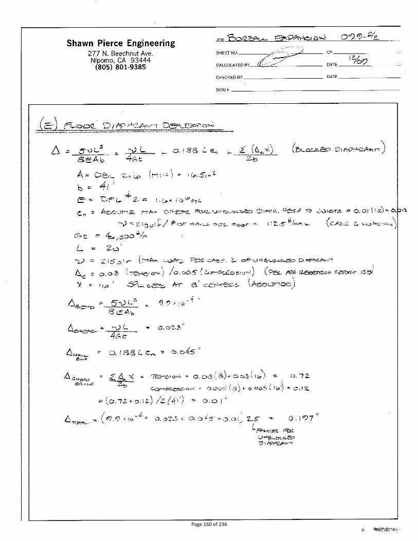
Page 160 of 236
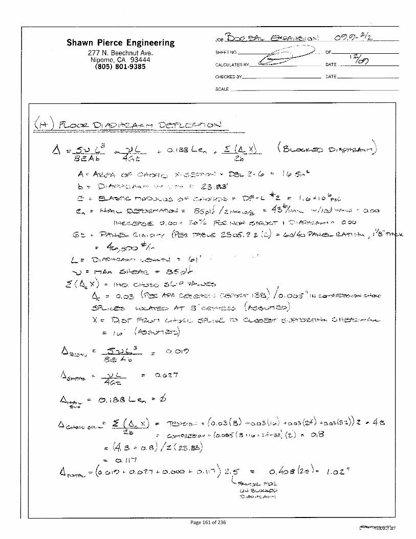
Page 161 of 236

Page 162 of 236

Page 163 of 236

Page 164 of 236
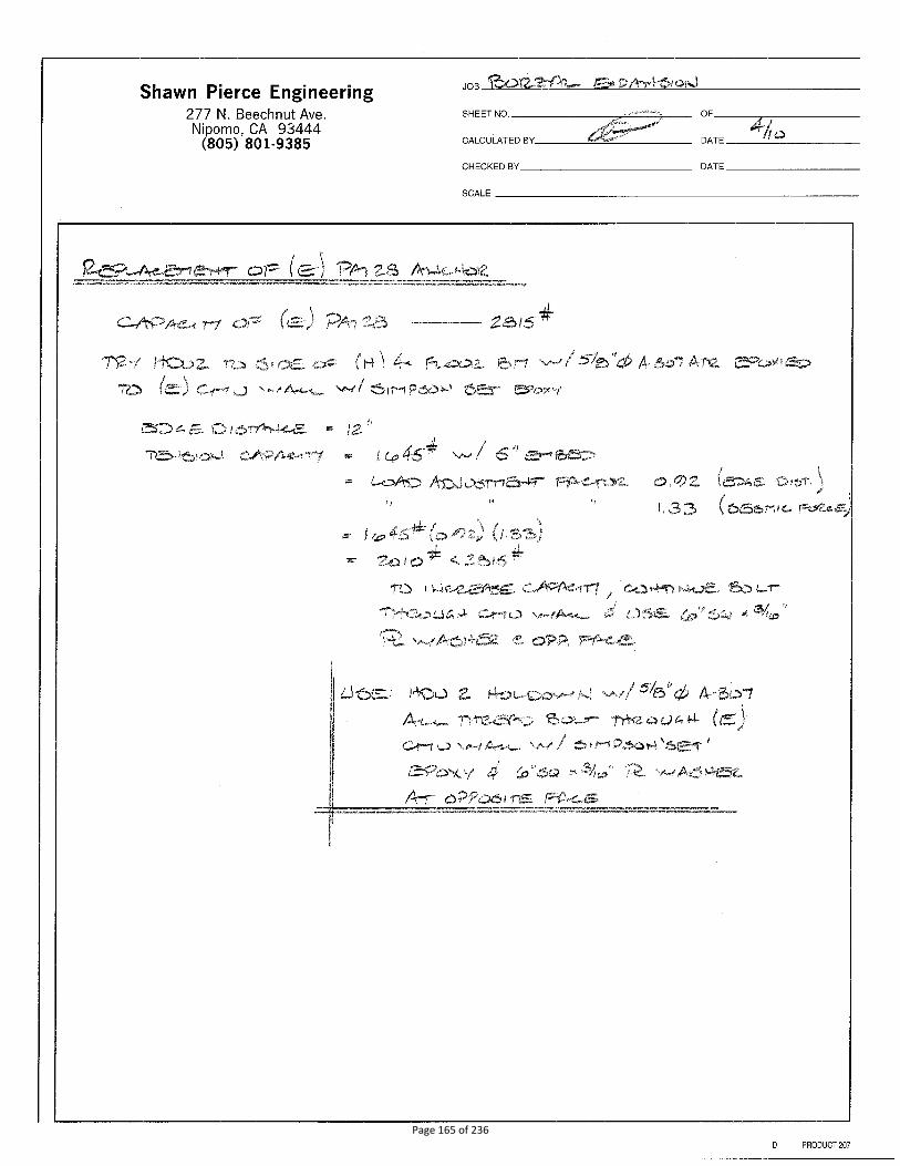
Page 165 of 236

LATERAL ANALYSIS
Conference Room Expansion
Page 166 of 236
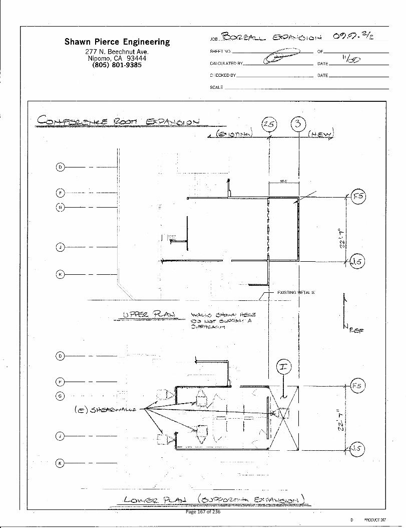
Page 167 of 236

Page 168 of 236

Page 169 of 236

Steel Column ENERCALC, INC. 1983-2009, Ver: 6.0.24, N:40336License Owner : PIERCE ENGINEERINGLic. # : KW-06008640
File: Z:\@Shawn Pierce Engineering\09_Projects\Borzal Addition_02\Engineering\Design\melford borzall expansion.ec6Printed: 17 NOV 2009, 2:03PM
Description : Cantilevered Column at Line 3
Shawn Pierce Engineering277 N. Beechnut AveNipomo, CA 93444Phone: (805) 801-9385Email: [email protected]
Title : Melford Borzall Expansion Job # 09.9-2/2
Project Desc.:Dsgnr: Shawn D. Pierce
Project Notes :
.Code Ref : 2006 IBC, AISC Manual 13th EditionGeneral Information
Steel Stress GradeTop Free, Bottom FixedAnalysis Method :
, A-500, Grade B, Fy = 46 ksi, Carbon Steel
11.50Overall Column Height
ft
Top & Bottom Fixity
Allowable Stress
Fy : Steel Yieldksi29,000.0ksi
Steel Section Name : HSS6X6X3/16
46.0
ft
E : Elastic Bending ModulusY-Y (depth) axis :X-X (width) axis :
Unbraced Length for Y-Y Axis buckling = 10 ft, K = 2.1Unbraced Length for X-X Axis buckling = 10ft, K = 2.1
Brace condition for deflection (buckling) along columns :
Load Combination :
2006 IBC & ASCE 7-05
.Service loads entered. Load Factors will be applied for calculations.Applied LoadsColumn self weight included : 166.83 lbs * Dead Load FactorAXIAL LOADS . . . Floor Beam on Line 3: Axial Load at 11.50 ft, D = 2.920, L = 7.035 kBENDING LOADS . . . Seismic Load: Lat. Point Load at 11.50 ft creating Mx-x, E = 1.090 k
.DESIGN SUMMARY
PASS Max. Axial+Bending Stress Ratio = 0.4818
Location of max.above base 0.0 ft
3.087 k51.146 k
8.775 k-ft
Load Combination +D+0.70E+H
Load Combination +D+0.70E+H
19.809 k-ft
Bending & Shear Check Results
PASS Maximum Shear Stress Ratio =
0.7630 k
0.02270 : 1
Location of max.above base 0.0 ftAt maximum location values are . . .
: 1
At maximum location values are . . .
k
19.431 k-ft0.0 k-ft
Pu : AxialPn / Omega : AllowableMu-x : AppliedMn-x / Omega : AllowableMu-y : AppliedMn-y / Omega : Allowable
Vu : AppliedVn / Omega : Allowable
Maximum SERVICE Load Reactions . .
(see tab for all)
Top along X-X 0.0 kBottom along X-X 0.0 kTop along Y-Y 0.0 kBottom along Y-Y 1.090 k
Maximum SERVICE Load Deflections . . .Along Y-Y -1.469 in at 11.50 ft above base
for load combination :E Only
Along X-X 0.0 in at 0.0 ft above basefor load combination :
33.613
.
Load Combination Stress Ratio Location Stress Ratio Status LocationStatusMaximum Axial + Bending Stress Ratios Maximum Shear Ratios
Load Combination Results
+D PASS PASS 0.00 0.000 0.00 ftft 0.060+D+L+H PASS PASS 0.00 0.000 0.00 ftft 0.198+D+Lr+H PASS PASS 0.00 0.000 0.00 ftft 0.060+D+0.750Lr+0.750L+H PASS PASS 0.00 0.000 0.00 ftft 0.164+D+0.70E+H PASS PASS 0.00 0.023 0.00 ftft 0.482+D-0.70E+H PASS PASS 0.00 0.023 0.00 ftft 0.482+D+0.750Lr+0.750L+0.5250E+H PASS PASS 0.00 0.017 0.00 ftft 0.420+D+0.750Lr+0.750L-0.5250E+H PASS PASS 0.00 0.017 0.00 ftft 0.420+D+0.750L+0.750S+0.5250E+H PASS PASS 0.00 0.017 0.00 ftft 0.420+D+0.750L+0.750S-0.5250E+H PASS PASS 0.00 0.017 0.00 ftft 0.420+0.60D+0.70E+H PASS PASS 0.00 0.023 0.00 ftft 0.470+0.60D-0.70E+H PASS PASS 0.00 0.023 0.00 ftft 0.470
.Note: Only non-zero reactions are listed.
Load CombinationX-X Axis Reaction Y-Y Axis Reaction
@ Base @ Top @ Base @ Top
Maximum Reactions - Unfactored
D OnlyL OnlyE Only 1.090-E Only -1.090
.
Page 170 of 236
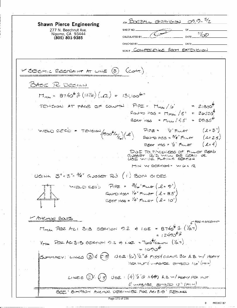
Page 171 of 236

Steel Base Plate Design ENERCALC, INC. 1983-2009, Ver: 6.0.24, N:40336License Owner : PIERCE ENGINEERINGLic. # : KW-06008640
File: Z:\@Shawn Pierce Engineering\09_Projects\Borzal Addition_02\Engineering\Design\melford borzall expansion.ec6Printed: 17 NOV 2009, 2:18PM
Description : Base Plate - Column at Intersection of Lines J.5 & 3
Shawn Pierce Engineering277 N. Beechnut AveNipomo, CA 93444Phone: (805) 801-9385Email: [email protected]
Title : Melford Borzall Expansion Job # 09.9-2/2
Project Desc.:Dsgnr: Shawn D. Pierce
Project Notes :
General Information
Material PropertiesAllowable Stress Design
Concrete Support f'c 2.50 ksiAllowable Bearing Fp per J8 3.188 ksi
1.0ABIF : Allowable Bearing Increase FactorASIF : Allowable Stress Increase Factor 1.0
: ASD Safety Factor. 2.50cSteel Plate Fy = 36.0 ksi
Assumed Bearing Area :Full Bearing
Calculations per 13th AISC & AISC Design Guide No. 1, 1990 by DeWolf & Ricker
=
AISC Design Method
Column Properties
1'-6"
2'-0
"
1'-0"
1'-0
"X
Y
Steel Section : HSS6X6X3/16Depth
0.174 in
in in^23.986 Area
Support width along "X" 24.0 inLength along "Z' 18.0 in
Support Dimensions
Column assumed welded to base plate.
Width 6 inFlange Thickness
Ixx in^4in^4
Web Thickness in
Plate DimensionsN : Length 12.0 inB : Width 12.0 inThickness 0.750 in
Iyy
Y YX X
Column & Plate
Applied Loads
1.090 12.490
" P " = Gravity load, "+" sign is downward.
kk
P-Yk
kkkk
"+" Moments create higher soil pressure at +Z edge.
M-X
k-ftk-ftk-ftk-ftk-ftk-ft
k-ftV-Z
D : Dead Load .......L : Live .......Lr : Roof Live .........S : Snow ................W : Wind ................E : Earthquake ...............
k
H : Lateral Earth ......... k
kkkk
k
"+" Shears push plate towards +Z edge.
Anchor BoltsAnchor Bolt
6.1802.570
2.03.0
Anchor Bolt or Rod Description
Number of Bolts in each Row...................
k
Number of Bolt Rows........................
Max of Tension or Pullout Capacity...........Shear Capacity......................................... k
1.50 inEdge distance : bolt to plate...................
Row Spacing................................. 4.50 in
Page 172 of 236

Steel Base Plate Design ENERCALC, INC. 1983-2009, Ver: 6.0.24, N:40336License Owner : PIERCE ENGINEERINGLic. # : KW-06008640
File: Z:\@Shawn Pierce Engineering\09_Projects\Borzal Addition_02\Engineering\Design\melford borzall expansion.ec6Printed: 17 NOV 2009, 2:12PM
Description : Base Plate - Column at Intersection of Lines J.5 & 3
Shawn Pierce Engineering277 N. Beechnut AveNipomo, CA 93444Phone: (805) 801-9385Email: [email protected]
Title : Melford Borzall Expansion Job # 09.9-2/2
Project Desc.:Dsgnr: Shawn D. Pierce
Project Notes :
General Information
Material PropertiesAllowable Stress Design
Concrete Support f'c 2.50 ksiAllowable Bearing Fp per J8 3.188 ksi
1.0ABIF : Allowable Bearing Increase FactorASIF : Allowable Stress Increase Factor 1.0
: ASD Safety Factor. 2.50cSteel Plate Fy = 36.0 ksi
Assumed Bearing Area :Full Bearing
Calculations per 13th AISC & AISC Design Guide No. 1, 1990 by DeWolf & Ricker
=
AISC Design Method
Column Properties
1'-6"
2'-0
"
1'-0"
1'-0
"X
Y
Steel Section : HSS6X6X3/16Depth
0.174 in
in in^23.986 Area
Support width along "X" 24.0 inLength along "Z' 18.0 in
Support Dimensions
Column assumed welded to base plate.
Width 6 inFlange Thickness
Ixx in^4in^4
Web Thickness in
Plate DimensionsN : Length 12.0 inB : Width 12.0 inThickness 0.750 in
Iyy
Y YX X
Column & Plate
Applied Loads
1.090 12.490
" P " = Gravity load, "+" sign is downward.
kk
P-Yk
kkkk
"+" Moments create higher soil pressure at +Z edge.
M-X
k-ftk-ftk-ftk-ftk-ftk-ft
k-ftV-Z
D : Dead Load .......L : Live .......Lr : Roof Live .........S : Snow ................W : Wind ................E : Earthquake ...............
k
H : Lateral Earth ......... k
kkkk
k
"+" Shears push plate towards +Z edge.
Anchor BoltsAnchor Bolt
6.1802.570
2.02.0
Anchor Bolt or Rod Description
Number of Bolts in each Row...................
k
Number of Bolt Rows........................
Max of Tension or Pullout Capacity...........Shear Capacity......................................... k
1.50 inEdge distance : bolt to plate...................
Row Spacing................................. 9.0 in
Page 173 of 236

Anchor Calculations
Anchor Designer for ACI 318 (Version 4.2.0.0)
Job Name : Borzall Expansion Date/Time : 11/5/2009 2:03:41 PM
1) Input
Calculation Method : ACI 318 Appendix D For Cracked Concrete Calculation Type : Design
a) LayoutAnchor : 1/2" PAB4 Number of Anchors : 6Steel Grade: AB Embedment Depth : 16 inBuilt-up Grout Pads : Yes
Anchor Layout Dimensions : cx1 : 13.5 in
cx2 : 13.5 in
cy1 : 6 in
cy2 : 22 in
bx1 : 1.5 in
bx2 : 1.5 in
by1 : 1.5 in
by2 : 1.5 in
sx1 : 9 in
sy1 : 4.5 in
Page 1 of 10
11/5/2009about:blank
Page 174 of 236

sy2 : 4.5 in
WARNING: EXCESS BEARING PRESSURE! Calculated bearing pressure is 3072.26 psi and exceeds the permissible bearing stress of Fp per ACI 318 Section 10.17. Designer must exercise own judgement to determine if this design is suitable.
b) Base Material
Concrete : Normal weight f'c : 2500.0 psi
Cracked Concrete : Yes c,V : 1.20
Condition : A tension and shear Fp : 1381.3 psi
Thickness, h : 24 inSupplementary edge reinforcement : No
c) Factored LoadsLoad factor source : ACI 318 Section 9.2Nua : 0 lb Vuax : 0 lb
Vuay : -1090 lb Mux : -12490 lb*ft
Muy : 0 lb*ft
ex : 0 in
ey : 1.8125 in
Moderate/high seismic risk or intermediate/high design category : YesApply entire shear load at front row for breakout : No d) Anchor Parameters
Anchor Model = PAB4 do = 0.5 in
Category = N/A hef = 15 in
hmin = 16.75 in cac = 22.5 in
cmin = 3 in smin = 3 in
Ductile = Yes
2) Tension Force on Each Individual Anchor
Anchor #1 Nua1 = 5784.02 lb
Anchor #2 Nua2 = 5784.02 lb
Anchor #3 Nua3 = 3046.53 lb
Anchor #4 Nua4 = 3046.53 lb
Anchor #5 Nua5 = 309.03 lb
Anchor #6 Nua6 = 309.03 lb
Page 2 of 10
11/5/2009about:blank
Page 175 of 236
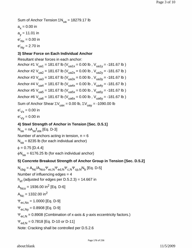
Sum of Anchor Tension Nua = 18279.17 lb
ax = 0.00 in
ay = 11.01 in
e'Nx = 0.00 in
e'Ny = 2.70 in
3) Shear Force on Each Individual Anchor
Resultant shear forces in each anchor:Anchor #1 Vua1 = 181.67 lb (Vua1x = 0.00 lb , Vua1y = -181.67 lb )
Anchor #2 Vua2 = 181.67 lb (Vua2x = 0.00 lb , Vua2y = -181.67 lb )
Anchor #3 Vua3 = 181.67 lb (Vua3x = 0.00 lb , Vua3y = -181.67 lb )
Anchor #4 Vua4 = 181.67 lb (Vua4x = 0.00 lb , Vua4y = -181.67 lb )
Anchor #5 Vua5 = 181.67 lb (Vua5x = 0.00 lb , Vua5y = -181.67 lb )
Anchor #6 Vua6 = 181.67 lb (Vua6x = 0.00 lb , Vua6y = -181.67 lb )
Sum of Anchor Shear Vuax = 0.00 lb, Vuay = -1090.00 lb
e'Vx = 0.00 in
e'Vy = 0.00 in
4) Steel Strength of Anchor in Tension [Sec. D.5.1]Nsa = nAsefuta [Eq. D-3]
Number of anchors acting in tension, n = 6Nsa = 8235 lb (for each individual anchor)
= 0.75 [D.4.4]
Nsa = 6176.25 lb (for each individual anchor)
5) Concrete Breakout Strength of Anchor Group in Tension [Sec. D.5.2]
Ncbg = ANc/ANcoec,Ned,Nc,Ncp,NNb [Eq. D-5]
Number of influencing edges = 4hef (adjusted for edges per D.5.2.3) = 14.667 in
ANco = 1936.00 in2 [Eq. D-6]
ANc = 1332.00 in2
ec,Nx = 1.0000 [Eq. D-9]
ec,Ny = 0.8908 [Eq. D-9]
ec,N = 0.8908 (Combination of x-axis & y-axis eccentricity factors.)
ed,N = 0.7818 [Eq. D-10 or D-11]
Note: Cracking shall be controlled per D.5.2.6
Page 3 of 10
11/5/2009about:blank
Page 176 of 236
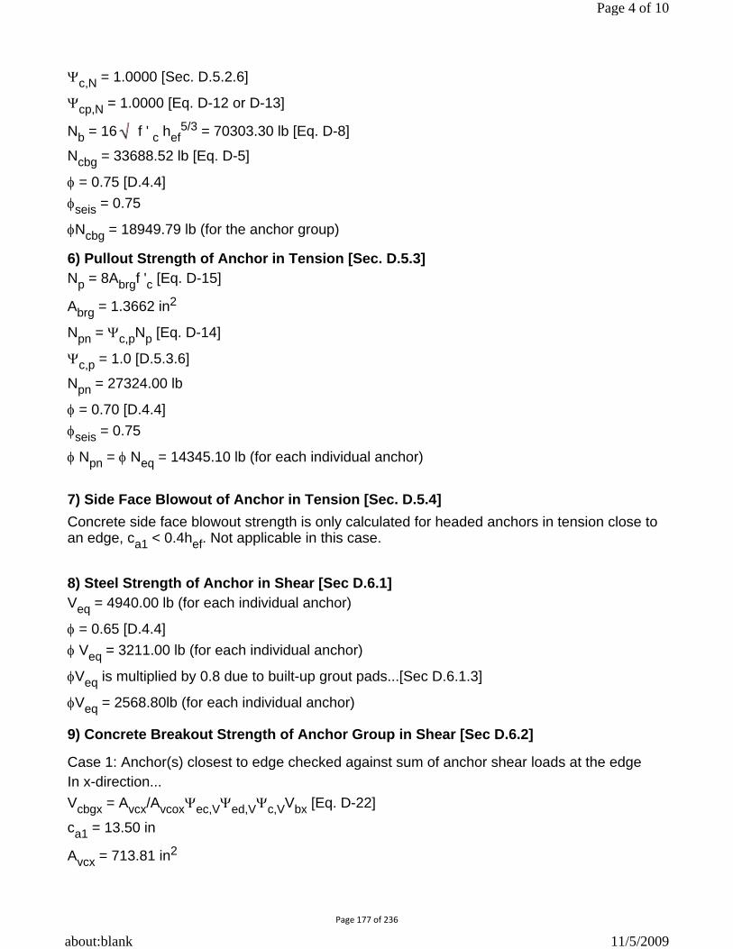
c,N = 1.0000 [Sec. D.5.2.6]
cp,N = 1.0000 [Eq. D-12 or D-13]
Nb = 16 f ' c hef5/3 = 70303.30 lb [Eq. D-8]
Ncbg = 33688.52 lb [Eq. D-5]
= 0.75 [D.4.4]
seis = 0.75
Ncbg = 18949.79 lb (for the anchor group)
6) Pullout Strength of Anchor in Tension [Sec. D.5.3] Np = 8Abrgf 'c [Eq. D-15]
Abrg = 1.3662 in2
Npn = c,pNp [Eq. D-14]
c,p = 1.0 [D.5.3.6]
Npn = 27324.00 lb
= 0.70 [D.4.4]
seis = 0.75
Npn = Neq = 14345.10 lb (for each individual anchor)
7) Side Face Blowout of Anchor in Tension [Sec. D.5.4]
Concrete side face blowout strength is only calculated for headed anchors in tension close to an edge, ca1 < 0.4hef. Not applicable in this case.
8) Steel Strength of Anchor in Shear [Sec D.6.1] Veq = 4940.00 lb (for each individual anchor)
= 0.65 [D.4.4]
Veq = 3211.00 lb (for each individual anchor)
Veq is multiplied by 0.8 due to built-up grout pads...[Sec D.6.1.3]
Veq = 2568.80lb (for each individual anchor)
9) Concrete Breakout Strength of Anchor Group in Shear [Sec D.6.2]
Case 1: Anchor(s) closest to edge checked against sum of anchor shear loads at the edge In x-direction...
Vcbgx = Avcx/Avcoxec,Ved,Vc,VVbx [Eq. D-22]
ca1 = 13.50 in
Avcx = 713.81 in2
Page 4 of 10
11/5/2009about:blank
Page 177 of 236

Avcox = 820.13 in2 [Eq. D-23]
ec,V = 1.0000 [Eq. D-26]
ed,V = 0.7889 [Eq. D-27 or D-28]
c,V = 1.2000 [Sec. D.6.2.7]
Vbx = 7(le/do)0.2 do f'c(ca1)1.5 [Eq. D-24]
le = 4.00 in
Vbx = 18606.80 lb
Vcbgx = 15331.08 lb [Eq. D-22]
= 0.75
seis = 0.75
Vcbgx = 8623.74 lb (for the anchor group)
In y-direction...
Vcbgy = Avcy/Avcoyec,Ved,Vc,VVby [Eq. D-22]
ca1 = 6.00 in
Avcy = 243.00 in2
Avcoy = 162.00 in2 [Eq. D-23]
ec,V = 1.0000 [Eq. D-26]
ed,V = 1.0000 [Eq. D-27 or D-28]
c,V = 1.2000 [Sec. D.6.2.7]
Vby = 7(le/do)0.2 do f'c(ca1)1.5 [Eq. D-24]
le = 4.00 in
Vby = 5513.13 lb
Vcbgy = 9923.63 lb [Eq. D-22]
= 0.75
seis = 0.75
Vcbgy = 5582.04 lb (for the anchor group)
Case 2: Anchor(s) furthest from edge checked against total shear load In x-direction...
Vcbgx = Avcx/Avcoxec,Ved,Vc,VVbx [Eq. D-22]
ca1 = 16.00 in (adjusted for edges per D.6.2.4)
Avcx = 888.00 in2
Avcox = 1152.00 in2 [Eq. D-23]
Page 5 of 10
11/5/2009about:blank
Page 178 of 236
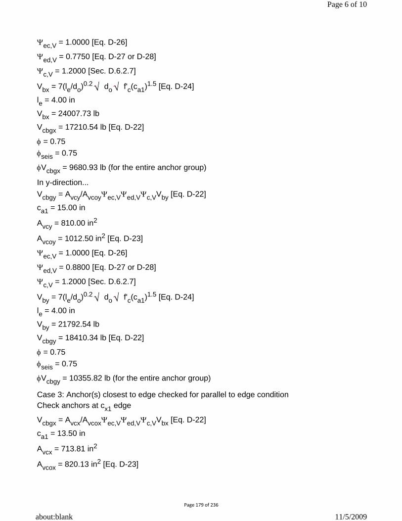
ec,V = 1.0000 [Eq. D-26]
ed,V = 0.7750 [Eq. D-27 or D-28]
c,V = 1.2000 [Sec. D.6.2.7]
Vbx = 7(le/do)0.2 do f'c(ca1)1.5 [Eq. D-24]
le = 4.00 in
Vbx = 24007.73 lb
Vcbgx = 17210.54 lb [Eq. D-22]
= 0.75
seis = 0.75
Vcbgx = 9680.93 lb (for the entire anchor group)
In y-direction...
Vcbgy = Avcy/Avcoyec,Ved,Vc,VVby [Eq. D-22]
ca1 = 15.00 in
Avcy = 810.00 in2
Avcoy = 1012.50 in2 [Eq. D-23]
ec,V = 1.0000 [Eq. D-26]
ed,V = 0.8800 [Eq. D-27 or D-28]
c,V = 1.2000 [Sec. D.6.2.7]
Vby = 7(le/do)0.2 do f'c(ca1)1.5 [Eq. D-24]
le = 4.00 in
Vby = 21792.54 lb
Vcbgy = 18410.34 lb [Eq. D-22]
= 0.75
seis = 0.75
Vcbgy = 10355.82 lb (for the entire anchor group)
Case 3: Anchor(s) closest to edge checked for parallel to edge condition Check anchors at cx1 edge
Vcbgx = Avcx/Avcoxec,Ved,Vc,VVbx [Eq. D-22]
ca1 = 13.50 in
Avcx = 713.81 in2
Avcox = 820.13 in2 [Eq. D-23]
Page 6 of 10
11/5/2009about:blank
Page 179 of 236

ec,V = 1.0000 [Eq. D-26]
ed,V = 1.0000 [Sec. D.6.2.1(c)]
c,V = 1.2000 [Sec. D.6.2.7]
Vbx = 7(le/do)0.2 do f'c(ca1)1.5 [Eq. D-24]
le = 4.00 in
Vbx = 18606.80 lb
Vcbgx = 19433.77 lb [Eq. D-22]
Vcbgy = 2 * Vcbgx [Sec. D.6.2.1(c)]
Vcbgy = 38867.54 lb
= 0.75
seis = 0.75
Vcbgy = 21862.99 lb (for the anchor group)
Check anchors at cy1 edge
Vcbgy = Avcy/Avcoyec,Ved,Vc,VVby [Eq. D-22]
ca1 = 6.00 in
Avcy = 243.00 in2
Avcoy = 162.00 in2 [Eq. D-23]
ec,V = 1.0000 [Eq. D-26]
ed,V = 1.0000 [Sec. D.6.2.1(c)]
c,V = 1.2000 [Sec. D.6.2.7]
Vby = 7(le/do)0.2 do f'c(ca1)1.5 [Eq. D-24]
le = 4.00 in
Vby = 5513.13 lb
Vcbgy = 9923.63 lb [Eq. D-22]
Vcbgx = 2 * Vcbgy [Sec. D.6.2.1(c)]
Vcbgx = 19847.25 lb
= 0.75
seis = 0.75
Vcbgx = 11164.08 lb (for the anchor group)
Check anchors at cx2 edge
Vcbgx = Avcx/Avcoxec,Ved,Vc,VVbx [Eq. D-22]
Page 7 of 10
11/5/2009about:blank
Page 180 of 236

ca1 = 13.50 in
Avcx = 713.81 in2
Avcox = 820.13 in2 [Eq. D-23]
ec,V = 1.0000 [Eq. D-26]
ed,V = 1.0000 [Eq. D-27 or D-28] [Sec. D.6.2.1(c)]
c,V = 1.2000 [Sec. D.6.2.7]
Vbx = 7(le/do)0.2 do f'c(ca1)1.5 [Eq. D-24]
le = 4.00 in
Vbx = 18606.80 lb
Vcbgx = 19433.77 lb [Eq. D-22]
Vcbgy = 2 * Vcbgx [Sec. D.6.2.1(c)]
Vcbgy = 38867.54 lb
= 0.75
seis = 0.75
Vcbgy = 21862.99 lb (for the anchor group)
Check anchors at cy2 edge
Vcbgy = Avcy/Avcoyec,Ved,Vc,VVby [Eq. D-22]
ca1 = 16.00 in (adjusted for edges per D.6.2.4)
Avcy = 864.00 in2
Avcoy = 1152.00 in2 [Eq. D-23]
ec,V = 1.0000 [Eq. D-26]
ed,V = 1.0000 [Sec. D.6.2.1(c)]
c,V = 1.2000 [Sec. D.6.2.7]
Vby = 7(le/do)0.2 do f'c(ca1)1.5 [Eq. D-24]
le = 4.00 in
Vby = 24007.73 lb
Vcbgy = 21606.95 lb [Eq. D-22]
Vcbgx = 2 * Vcbgy [Sec. D.6.2.1(c)]
Vcbgx = 43213.91 lb
= 0.75
seis = 0.75
Page 8 of 10
11/5/2009about:blank
Page 181 of 236

Vcbgx = 24307.82 lb (for the anchor group)
10) Concrete Pryout Strength of Anchor Group in Shear [Sec. D.6.3]
Vcpg = kcpNcbg [Eq. D-30]
kcp = 2 [Sec. D.6.3.1]
eNx = 0.00 in (Applied shear load eccentricity relative to anchor group c.g.)
eNy = 1.81 in (Applied shear load eccentricity relative to anchor group c.g.)
ec,Nx = 1.0000 [Eq. D-9] (Calulated using applied shear load eccentricity)
ec,Ny = 0.9239 [Eq. D-9] (Calulated using applied shear load eccentricity)
ec,N' = 0.9239 (Combination of x-axis & y-axis eccentricity factors)
Ncbg = (ANca/ANc)(ec,N'/ec,N)Ncbg
Ncbg = 33688.52 lb (from Section (5) of calculations)
ANc = 1332.00 in2 (from Section (5) of calculations)
ANca = 1332.00 in2 (considering all anchors)
ec,N = 0.8908 (from Section(5) of calculations)
Ncbg = 34938.00 lb (considering all anchors)
Vcpg = 69876.00 lb
= 0.70 [D.4.4]
seis = 0.75
Vcpg = 36684.90 lb (for the anchor group)
11) Check Demand/Capacity Ratios [Sec. D.7]
Tension - Steel : 0.9365- Breakout : 0.9646- Pullout : 0.4032- Sideface Blowout : N/A
Shear - Steel : 0.0707- Breakout (case 1) : 0.0651- Breakout (case 2) : 0.1053- Breakout (case 3) : 0.0249- Pryout : 0.0297
V.Max(0.11) <= 0.2 and T.Max(0.96) <= 1.0 [Sec D.7.1]
Interaction check: PASSUse 1/2" diameter PAB4 anchor(s) with 16 in. embedment
BRITTLE FAILURE GOVERNS: Governing anchor failure mode is brittle failure. Per 2006 IBC
Page 9 of 10
11/5/2009about:blank
Page 182 of 236
Section 1908.1.16, anchors shall be governed by a ductile steel element in structures assigned to Seismic Design Category C, D, E, or F. Alternatively the minimum design strength of the anchor(s) shall be at least 2.5 times the factored forces or the anchor attachment to the structure shall undergo ductile yielding at a load level less than the design strength of the anchor(s). Designer must exercise own judgement to determine if this design is suitable.
Page 10 of 10
11/5/2009about:blank
Page 183 of 236

Steel Base Plate Design ENERCALC, INC. 1983-2008, Ver: 6.0.221, N:40336License Owner : PIERCE ENGINEERINGLic. # : KW-06008640
File: Y:\@Shawn Pierce Engineering\09_Projects\Borzal Addition_02\Engineering\Design\melford borzall expansion.ec6Printed: 9 NOV 2009, 9:19AM
Description : Base Plate - Column at Intersection of Lines F.5 & 3
Title Block Line 1You can changes this areausing the "Settings" menu itemand then using the "Printing &Title Block" selection.Title Block Line 6
Title : Melford Borzall Expansion Job # 09.9-2/2
Project Desc.:Dsgnr: Shawn D. Pierce
Project Notes :
General Information
Material PropertiesAllowable Stress Design
Concrete Support f'c 2.50 ksiAllowable Bearing Fp per J8 3.188 ksi
1.0ABIF : Allowable Bearing Increase FactorASIF : Allowable Stress Increase Factor 1.0
: ASD Safety Factor. 2.50cSteel Plate Fy = 36.0 ksi
Assumed Bearing Area :Full Bearing
Calculations per 13th AISC & AISC Design Guide No. 1, 1990 by DeWolf & Ricker
=
AISC Design Method
Column Properties
1'-6"
2'-0
"
1'-0"
1'-0"X
Y
Steel Section : HSS6X6X3/16Depth
0.174 in
in in^23.986 Area
Support width along "X" 24.0 inLength along "Z' 18.0 in
Support Dimensions
Column assumed welded to base plate.
Width 6 inFlange Thickness
Ixx 22.3 in^422.3 in^4
Web Thickness in
Plate DimensionsN : Length 12.0 inB : Width 12.0 inThickness 0.750 in
0Iyy
Y YX X
Column & Plate
Applied Loads
1.090 12.490
" P " = Gravity load, "+" sign is downward.
kk
P-Yk
kkkk
"+" Moments create higher soil pressure at +Z edge.
M-X
k-ftk-ftk-ftk-ftk-ftk-ft
k-ftV-Z
D : Dead Load .......L : Live .......Lr : Roof Live .........S : Snow ................W : Wind ................E : Earthquake ...............
k
H : Lateral Earth ......... k
kkkk
k
"+" Shears push plate towards +Z edge.
Anchor BoltsAnchor Bolt
6.1802.570
2.03.0
Anchor Bolt or Rod Description
Number of Bolts in each Row...................
k
Number of Bolt Rows........................
Max of Tension or Pullout Capacity...........Shear Capacity......................................... k
1.50 inEdge distance : bolt to plate...................
Row Spacing................................. 4.50 in
GOVERNING DESIGN LOAD CASE SUMMARYPlate Design Summary
Fp : Allowable :min( 0.85*f'c*sqrt(A2/A1), 1.7* f'c)*Ome
1.275 ksi
Bearing Stress OKfv : Actual ................................ 0.365 ksi
0.017Fv : Allowable = 0.60 * Fy / 1.5 (per G2) 21.557ksi
Stress Ratio .................Shear Stress OK
Stress Ratio .................
0.738
fu : Max. Plate Bearing Stress .... 0.364 ksi
Design Method Allowable Stress Design+D+0.70E+H
Governing Load Case Type Axial + Moment, Eccentricity <= L/6Design Plate Size 1'-0" x 1'-0" x 0 -3/4"Pa : Axial Load .... 0.000 kMa : Moment ........ 8.743 k-ft
Mu : Max. Moment ..................... 1.491 k-in
Governing Load Combination
fb : Max. Bending Stress ............... 15.905 ksiFb : Allowable :
Fy * ASIF / Omega 21.557 ksi
Bending Stress OKStress Ratio .................
0.286
Page 184 of 236
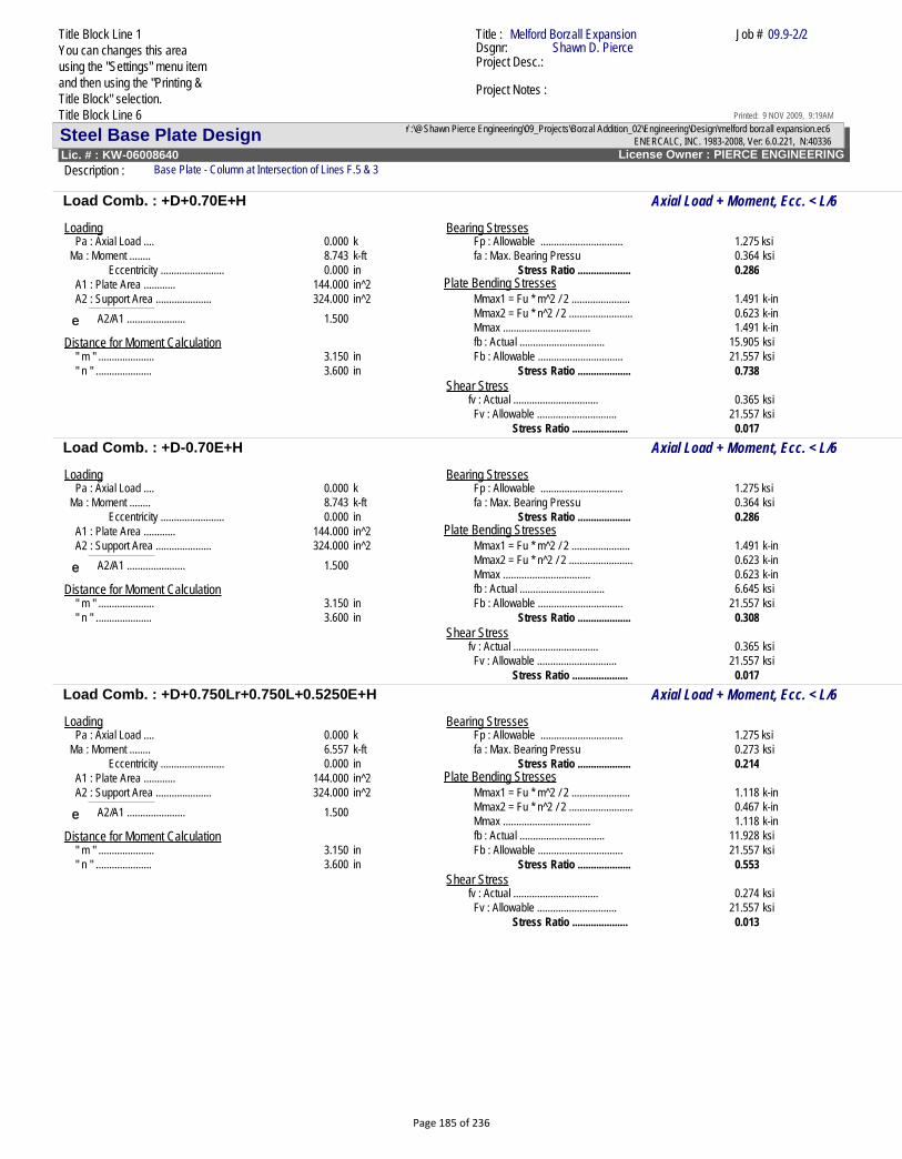
Steel Base Plate Design ENERCALC, INC. 1983-2008, Ver: 6.0.221, N:40336License Owner : PIERCE ENGINEERINGLic. # : KW-06008640
File: Y:\@Shawn Pierce Engineering\09_Projects\Borzal Addition_02\Engineering\Design\melford borzall expansion.ec6Printed: 9 NOV 2009, 9:19AM
Description : Base Plate - Column at Intersection of Lines F.5 & 3
Title Block Line 1You can changes this areausing the "Settings" menu itemand then using the "Printing &Title Block" selection.Title Block Line 6
Title : Melford Borzall Expansion Job # 09.9-2/2
Project Desc.:Dsgnr: Shawn D. Pierce
Project Notes :
Axial Load + Moment, Ecc. < L/6Load Comb. : +D+0.70E+H
LoadingPa : Axial Load .... 0.000 k
Bearing Stresses
A1 : Plate Area ............ 144.000 in^2
Fb : Allowable ................................ 21.557 ksi
A2 : Support Area ..................... 324.000 in^2
eA2/A1 ...................... 1.500
Mmax ................................. 1.491 k-in
Fp : Allowable ............................... 1.275 ksi
Distance for Moment Calculation
Ma : Moment ........ 8.743 k-ft
" m " ..................... 3.150 in
Eccentricity ........................ 0.000 in
" n " ..................... 3.600 in Stress Ratio .................... 0.738
fa : Max. Bearing Pressu 0.364 ksi
fb : Actual ................................ 15.905 ksi
Mmax1 = Fu * m^2 / 2 ...................... 1.491 k-inPlate Bending Stresses
Stress Ratio .................... 0.286
Mmax2 = Fu * n^2 / 2 ........................ 0.623 k-in
Shear Stressfv : Actual ................................ 0.365 ksi
Fv : Allowable .............................. 21.557 ksiStress Ratio ..................... 0.017
Axial Load + Moment, Ecc. < L/6Load Comb. : +D-0.70E+H
LoadingPa : Axial Load .... 0.000 k
Bearing Stresses
A1 : Plate Area ............ 144.000 in^2
Fb : Allowable ................................ 21.557 ksi
A2 : Support Area ..................... 324.000 in^2
eA2/A1 ...................... 1.500
Mmax ................................. 0.623 k-in
Fp : Allowable ............................... 1.275 ksi
Distance for Moment Calculation
Ma : Moment ........ 8.743 k-ft
" m " ..................... 3.150 in
Eccentricity ........................ 0.000 in
" n " ..................... 3.600 in Stress Ratio .................... 0.308
fa : Max. Bearing Pressu 0.364 ksi
fb : Actual ................................ 6.645 ksi
Mmax1 = Fu * m^2 / 2 ...................... 1.491 k-inPlate Bending Stresses
Stress Ratio .................... 0.286
Mmax2 = Fu * n^2 / 2 ........................ 0.623 k-in
Shear Stressfv : Actual ................................ 0.365 ksi
Fv : Allowable .............................. 21.557 ksiStress Ratio ..................... 0.017
Axial Load + Moment, Ecc. < L/6Load Comb. : +D+0.750Lr+0.750L+0.5250E+H
LoadingPa : Axial Load .... 0.000 k
Bearing Stresses
A1 : Plate Area ............ 144.000 in^2
Fb : Allowable ................................ 21.557 ksi
A2 : Support Area ..................... 324.000 in^2
eA2/A1 ...................... 1.500
Mmax ................................. 1.118 k-in
Fp : Allowable ............................... 1.275 ksi
Distance for Moment Calculation
Ma : Moment ........ 6.557 k-ft
" m " ..................... 3.150 in
Eccentricity ........................ 0.000 in
" n " ..................... 3.600 in Stress Ratio .................... 0.553
fa : Max. Bearing Pressu 0.273 ksi
fb : Actual ................................ 11.928 ksi
Mmax1 = Fu * m^2 / 2 ...................... 1.118 k-inPlate Bending Stresses
Stress Ratio .................... 0.214
Mmax2 = Fu * n^2 / 2 ........................ 0.467 k-in
Shear Stressfv : Actual ................................ 0.274 ksi
Fv : Allowable .............................. 21.557 ksiStress Ratio ..................... 0.013
Page 185 of 236

Steel Base Plate Design ENERCALC, INC. 1983-2008, Ver: 6.0.221, N:40336License Owner : PIERCE ENGINEERINGLic. # : KW-06008640
File: Y:\@Shawn Pierce Engineering\09_Projects\Borzal Addition_02\Engineering\Design\melford borzall expansion.ec6Printed: 9 NOV 2009, 9:19AM
Description : Base Plate - Column at Intersection of Lines F.5 & 3
Title Block Line 1You can changes this areausing the "Settings" menu itemand then using the "Printing &Title Block" selection.Title Block Line 6
Title : Melford Borzall Expansion Job # 09.9-2/2
Project Desc.:Dsgnr: Shawn D. Pierce
Project Notes :
Axial Load + Moment, Ecc. < L/6Load Comb. : +D+0.750Lr+0.750L-0.5250E+H
LoadingPa : Axial Load .... 0.000 k
Bearing Stresses
A1 : Plate Area ............ 144.000 in^2
Fb : Allowable ................................ 21.557 ksi
A2 : Support Area ..................... 324.000 in^2
eA2/A1 ...................... 1.500
Mmax ................................. 0.467 k-in
Fp : Allowable ............................... 1.275 ksi
Distance for Moment Calculation
Ma : Moment ........ 6.557 k-ft
" m " ..................... 3.150 in
Eccentricity ........................ 0.000 in
" n " ..................... 3.600 in Stress Ratio .................... 0.231
fa : Max. Bearing Pressu 0.273 ksi
fb : Actual ................................ 4.984 ksi
Mmax1 = Fu * m^2 / 2 ...................... 1.118 k-inPlate Bending Stresses
Stress Ratio .................... 0.214
Mmax2 = Fu * n^2 / 2 ........................ 0.467 k-in
Shear Stressfv : Actual ................................ 0.274 ksi
Fv : Allowable .............................. 21.557 ksiStress Ratio ..................... 0.013
Axial Load + Moment, Ecc. < L/6Load Comb. : +D+0.750L+0.750S+0.5250E+H
LoadingPa : Axial Load .... 0.000 k
Bearing Stresses
A1 : Plate Area ............ 144.000 in^2
Fb : Allowable ................................ 21.557 ksi
A2 : Support Area ..................... 324.000 in^2
eA2/A1 ...................... 1.500
Mmax ................................. 1.118 k-in
Fp : Allowable ............................... 1.275 ksi
Distance for Moment Calculation
Ma : Moment ........ 6.557 k-ft
" m " ..................... 3.150 in
Eccentricity ........................ 0.000 in
" n " ..................... 3.600 in Stress Ratio .................... 0.553
fa : Max. Bearing Pressu 0.273 ksi
fb : Actual ................................ 11.928 ksi
Mmax1 = Fu * m^2 / 2 ...................... 1.118 k-inPlate Bending Stresses
Stress Ratio .................... 0.214
Mmax2 = Fu * n^2 / 2 ........................ 0.467 k-in
Shear Stressfv : Actual ................................ 0.274 ksi
Fv : Allowable .............................. 21.557 ksiStress Ratio ..................... 0.013
Axial Load + Moment, Ecc. < L/6Load Comb. : +D+0.750L+0.750S-0.5250E+H
LoadingPa : Axial Load .... 0.000 k
Bearing Stresses
A1 : Plate Area ............ 144.000 in^2
Fb : Allowable ................................ 21.557 ksi
A2 : Support Area ..................... 324.000 in^2
eA2/A1 ...................... 1.500
Mmax ................................. 0.467 k-in
Fp : Allowable ............................... 1.275 ksi
Distance for Moment Calculation
Ma : Moment ........ 6.557 k-ft
" m " ..................... 3.150 in
Eccentricity ........................ 0.000 in
" n " ..................... 3.600 in Stress Ratio .................... 0.231
fa : Max. Bearing Pressu 0.273 ksi
fb : Actual ................................ 4.984 ksi
Mmax1 = Fu * m^2 / 2 ...................... 1.118 k-inPlate Bending Stresses
Stress Ratio .................... 0.214
Mmax2 = Fu * n^2 / 2 ........................ 0.467 k-in
Shear Stressfv : Actual ................................ 0.274 ksi
Fv : Allowable .............................. 21.557 ksiStress Ratio ..................... 0.013
Page 186 of 236
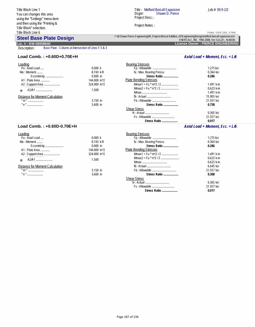
Steel Base Plate Design ENERCALC, INC. 1983-2008, Ver: 6.0.221, N:40336License Owner : PIERCE ENGINEERINGLic. # : KW-06008640
File: Y:\@Shawn Pierce Engineering\09_Projects\Borzal Addition_02\Engineering\Design\melford borzall expansion.ec6Printed: 9 NOV 2009, 9:19AM
Description : Base Plate - Column at Intersection of Lines F.5 & 3
Title Block Line 1You can changes this areausing the "Settings" menu itemand then using the "Printing &Title Block" selection.Title Block Line 6
Title : Melford Borzall Expansion Job # 09.9-2/2
Project Desc.:Dsgnr: Shawn D. Pierce
Project Notes :
Axial Load + Moment, Ecc. < L/6Load Comb. : +0.60D+0.70E+H
LoadingPa : Axial Load .... 0.000 k
Bearing Stresses
A1 : Plate Area ............ 144.000 in^2
Fb : Allowable ................................ 21.557 ksi
A2 : Support Area ..................... 324.000 in^2
eA2/A1 ...................... 1.500
Mmax ................................. 1.491 k-in
Fp : Allowable ............................... 1.275 ksi
Distance for Moment Calculation
Ma : Moment ........ 8.743 k-ft
" m " ..................... 3.150 in
Eccentricity ........................ 0.000 in
" n " ..................... 3.600 in Stress Ratio .................... 0.738
fa : Max. Bearing Pressu 0.364 ksi
fb : Actual ................................ 15.905 ksi
Mmax1 = Fu * m^2 / 2 ...................... 1.491 k-inPlate Bending Stresses
Stress Ratio .................... 0.286
Mmax2 = Fu * n^2 / 2 ........................ 0.623 k-in
Shear Stressfv : Actual ................................ 0.365 ksi
Fv : Allowable .............................. 21.557 ksiStress Ratio ..................... 0.017
Axial Load + Moment, Ecc. < L/6Load Comb. : +0.60D-0.70E+H
LoadingPa : Axial Load .... 0.000 k
Bearing Stresses
A1 : Plate Area ............ 144.000 in^2
Fb : Allowable ................................ 21.557 ksi
A2 : Support Area ..................... 324.000 in^2
eA2/A1 ...................... 1.500
Mmax ................................. 0.623 k-in
Fp : Allowable ............................... 1.275 ksi
Distance for Moment Calculation
Ma : Moment ........ 8.743 k-ft
" m " ..................... 3.150 in
Eccentricity ........................ 0.000 in
" n " ..................... 3.600 in Stress Ratio .................... 0.308
fa : Max. Bearing Pressu 0.364 ksi
fb : Actual ................................ 6.645 ksi
Mmax1 = Fu * m^2 / 2 ...................... 1.491 k-inPlate Bending Stresses
Stress Ratio .................... 0.286
Mmax2 = Fu * n^2 / 2 ........................ 0.623 k-in
Shear Stressfv : Actual ................................ 0.365 ksi
Fv : Allowable .............................. 21.557 ksiStress Ratio ..................... 0.017
Page 187 of 236

Anchor Calculations
Anchor Designer for ACI 318 (Version 4.2.0.0)
Job Name : Borzall Expansion Date/Time : 11/5/2009 3:53:26 PM
1) Input
Calculation Method : ACI 318 Appendix D For Cracked Concrete Calculation Type : Design
a) LayoutAnchor : 1/2" PAB4H Number of Anchors : 4Steel Grade: AB_H Embedment Depth : 12 inBuilt-up Grout Pads : Yes
Anchor Layout Dimensions : cx1 : 19.5 in
cx2 : 19.5 in
cy1 : 19.5 in
cy2 : 19.5 in
bx1 : 1.5 in
bx2 : 1.5 in
by1 : 1.5 in
by2 : 1.5 in
sx1 : 9 in
sy1 : 4.5 in
Page 1 of 10
11/5/2009about:blank
Page 188 of 236

WARNING: EXCESS BEARING PRESSURE! Calculated bearing pressure is 7740.14 psi and exceeds the permissible bearing stress of Fp per ACI 318 Section 10.17. Designer must exercise own judgement to determine if this design is suitable.
b) Base Material
Concrete : Normal weight f'c : 2500.0 psi
Cracked Concrete : Yes c,V : 1.20
Condition : A tension and shear Fp : 1381.3 psi
Thickness, h : 24 inSupplementary edge reinforcement : No
c) Factored LoadsLoad factor source : ACI 318 Section 9.2Nua : 0 lb Vuax : 0 lb
Vuay : -1090 lb Mux : -12490 lb*ft
Muy : 0 lb*ft
ex : 0 in
ey : 0 in
Moderate/high seismic risk or intermediate/high design category : YesApply entire shear load at front row for breakout : No d) Anchor Parameters
Anchor Model = PAB4H do = 0.5 in
Category = N/A hef = 11 in
hmin = 12.75 in cac = 16.5 in
cmin = 3 in smin = 3 in
Ductile = Yes
2) Tension Force on Each Individual Anchor
Anchor #1 Nua1 = 12767.49 lb
Anchor #2 Nua2 = 12767.49 lb
Anchor #3 Nua3 = 2050.51 lb
Anchor #4 Nua4 = 2050.51 lb
Sum of Anchor Tension Nua = 29636.00 lb
ax = 0.00 in
ay = 6.86 in
Page 2 of 10
11/5/2009about:blank
Page 189 of 236

e'Nx = 0.00 in
e'Ny = 1.63 in
3) Shear Force on Each Individual Anchor
Resultant shear forces in each anchor:Anchor #1 Vua1 = 272.50 lb (Vua1x = 0.00 lb , Vua1y = -272.50 lb )
Anchor #2 Vua2 = 272.50 lb (Vua2x = 0.00 lb , Vua2y = -272.50 lb )
Anchor #3 Vua3 = 272.50 lb (Vua3x = 0.00 lb , Vua3y = -272.50 lb )
Anchor #4 Vua4 = 272.50 lb (Vua4x = 0.00 lb , Vua4y = -272.50 lb )
Sum of Anchor Shear Vuax = 0.00 lb, Vuay = -1090.00 lb
e'Vx = 0.00 in
e'Vy = 0.00 in
4) Steel Strength of Anchor in Tension [Sec. D.5.1]Nsa = nAsefuta [Eq. D-3]
Number of anchors acting in tension, n = 4Nsa = 17040 lb (for each individual anchor)
= 0.75 [D.4.4]
Nsa = 12780.00 lb (for each individual anchor)
5) Concrete Breakout Strength of Anchor Group in Tension [Sec. D.5.2]
Ncbg = ANc/ANcoec,Ned,Nc,Ncp,NNb [Eq. D-5]
Number of influencing edges = 0hef = 11 in
h'ef = 11.458 in [Sec. D.5.2.8]
Note: ANco and ANc are calculated using h'ef for anchor with washer
ANco = 1181.64 in2 [Eq. D-6]
ANc = 1686.20 in2
ec,Nx = 1.0000 [Eq. D-9]
ec,Ny = 0.9102 [Eq. D-9]
ec,N = 0.9102 (Combination of x-axis & y-axis eccentricity factors.)
ed,N = 1.0000 [Eq. D-10 or D-11]
Note: Cracking shall be controlled per D.5.2.6
c,N = 1.0000 [Sec. D.5.2.6]
cp,N = 1.0000 [Eq. D-12 or D-13]
Page 3 of 10
11/5/2009about:blank
Page 190 of 236

Nb = 16 f ' c hef5/3 = 43525.57 lb [Eq. D-8]
Ncbg = 56535.34 lb [Eq. D-5]
= 0.75 [D.4.4]
seis = 0.75
Ncbg = 31801.13 lb (for the anchor group)
6) Pullout Strength of Anchor in Tension [Sec. D.5.3] Np = 8Abrgf 'c [Eq. D-15]
Abrg = 1.3662 in2
Npn = c,pNp [Eq. D-14]
c,p = 1.0 [D.5.3.6]
Npn = 27324.00 lb
= 0.70 [D.4.4]
seis = 0.75
Npn = Neq = 14345.10 lb (for each individual anchor)
7) Side Face Blowout of Anchor in Tension [Sec. D.5.4]
Concrete side face blowout strength is only calculated for headed anchors in tension close to an edge, ca1 < 0.4hef. Not applicable in this case.
8) Steel Strength of Anchor in Shear [Sec D.6.1] Veq = 10225.00 lb (for each individual anchor)
= 0.65 [D.4.4]
Veq = 6646.25 lb (for each individual anchor)
Veq is multiplied by 0.8 due to built-up grout pads...[Sec D.6.1.3]
Veq = 5317.00lb (for each individual anchor)
9) Concrete Breakout Strength of Anchor Group in Shear [Sec D.6.2]
Case 1: Anchor(s) closest to edge checked against sum of anchor shear loads at the edge In x-direction...
Vcbgx = Avcx/Avcoxec,Ved,Vc,VVbx [Eq. D-22]
ca1 = 16.00 in (adjusted for edges per D.6.2.4)
Avcx = 1044.00 in2
Avcox = 1152.00 in2 [Eq. D-23]
ec,V = 1.0000 [Eq. D-26]
Page 4 of 10
11/5/2009about:blank
Page 191 of 236
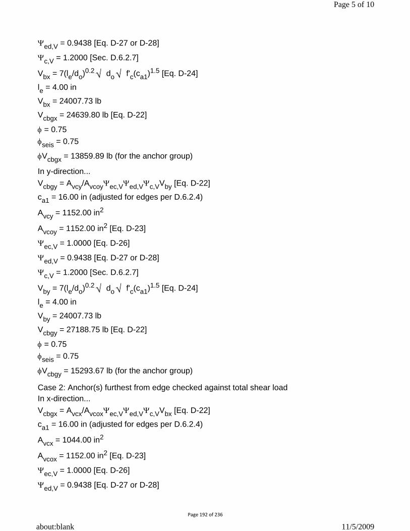
ed,V = 0.9438 [Eq. D-27 or D-28]
c,V = 1.2000 [Sec. D.6.2.7]
Vbx = 7(le/do)0.2 do f'c(ca1)1.5 [Eq. D-24]
le = 4.00 in
Vbx = 24007.73 lb
Vcbgx = 24639.80 lb [Eq. D-22]
= 0.75
seis = 0.75
Vcbgx = 13859.89 lb (for the anchor group)
In y-direction...
Vcbgy = Avcy/Avcoyec,Ved,Vc,VVby [Eq. D-22]
ca1 = 16.00 in (adjusted for edges per D.6.2.4)
Avcy = 1152.00 in2
Avcoy = 1152.00 in2 [Eq. D-23]
ec,V = 1.0000 [Eq. D-26]
ed,V = 0.9438 [Eq. D-27 or D-28]
c,V = 1.2000 [Sec. D.6.2.7]
Vby = 7(le/do)0.2 do f'c(ca1)1.5 [Eq. D-24]
le = 4.00 in
Vby = 24007.73 lb
Vcbgy = 27188.75 lb [Eq. D-22]
= 0.75
seis = 0.75
Vcbgy = 15293.67 lb (for the anchor group)
Case 2: Anchor(s) furthest from edge checked against total shear load In x-direction...
Vcbgx = Avcx/Avcoxec,Ved,Vc,VVbx [Eq. D-22]
ca1 = 16.00 in (adjusted for edges per D.6.2.4)
Avcx = 1044.00 in2
Avcox = 1152.00 in2 [Eq. D-23]
ec,V = 1.0000 [Eq. D-26]
ed,V = 0.9438 [Eq. D-27 or D-28]
Page 5 of 10
11/5/2009about:blank
Page 192 of 236

c,V = 1.2000 [Sec. D.6.2.7]
Vbx = 7(le/do)0.2 do f'c(ca1)1.5 [Eq. D-24]
le = 4.00 in
Vbx = 24007.73 lb
Vcbgx = 24639.80 lb [Eq. D-22]
= 0.75
seis = 0.75
Vcbgx = 13859.89 lb (for the entire anchor group)
In y-direction...
Vcbgy = Avcy/Avcoyec,Ved,Vc,VVby [Eq. D-22]
ca1 = 16.00 in (adjusted for edges per D.6.2.4)
Avcy = 1152.00 in2
Avcoy = 1152.00 in2 [Eq. D-23]
ec,V = 1.0000 [Eq. D-26]
ed,V = 0.9438 [Eq. D-27 or D-28]
c,V = 1.2000 [Sec. D.6.2.7]
Vby = 7(le/do)0.2 do f'c(ca1)1.5 [Eq. D-24]
le = 4.00 in
Vby = 24007.73 lb
Vcbgy = 27188.75 lb [Eq. D-22]
= 0.75
seis = 0.75
Vcbgy = 15293.67 lb (for the entire anchor group)
Case 3: Anchor(s) closest to edge checked for parallel to edge condition Check anchors at cx1 edge
Vcbgx = Avcx/Avcoxec,Ved,Vc,VVbx [Eq. D-22]
ca1 = 16.00 in (adjusted for edges per D.6.2.4)
Avcx = 1044.00 in2
Avcox = 1152.00 in2 [Eq. D-23]
ec,V = 1.0000 [Eq. D-26]
ed,V = 1.0000 [Sec. D.6.2.1(c)]
Page 6 of 10
11/5/2009about:blank
Page 193 of 236

c,V = 1.2000 [Sec. D.6.2.7]
Vbx = 7(le/do)0.2 do f'c(ca1)1.5 [Eq. D-24]
le = 4.00 in
Vbx = 24007.73 lb
Vcbgx = 26108.40 lb [Eq. D-22]
Vcbgy = 2 * Vcbgx [Sec. D.6.2.1(c)]
Vcbgy = 52216.80 lb
= 0.75
seis = 0.75
Vcbgy = 29371.95 lb (for the anchor group)
Check anchors at cy1 edge
Vcbgy = Avcy/Avcoyec,Ved,Vc,VVby [Eq. D-22]
ca1 = 16.00 in (adjusted for edges per D.6.2.4)
Avcy = 1152.00 in2
Avcoy = 1152.00 in2 [Eq. D-23]
ec,V = 1.0000 [Eq. D-26]
ed,V = 1.0000 [Sec. D.6.2.1(c)]
c,V = 1.2000 [Sec. D.6.2.7]
Vby = 7(le/do)0.2 do f'c(ca1)1.5 [Eq. D-24]
le = 4.00 in
Vby = 24007.73 lb
Vcbgy = 28809.27 lb [Eq. D-22]
Vcbgx = 2 * Vcbgy [Sec. D.6.2.1(c)]
Vcbgx = 57618.54 lb
= 0.75
seis = 0.75
Vcbgx = 32410.43 lb (for the anchor group)
Check anchors at cx2 edge
Vcbgx = Avcx/Avcoxec,Ved,Vc,VVbx [Eq. D-22]
ca1 = 16.00 in (adjusted for edges per D.6.2.4)
Avcx = 1044.00 in2
Page 7 of 10
11/5/2009about:blank
Page 194 of 236

Avcox = 1152.00 in2 [Eq. D-23]
ec,V = 1.0000 [Eq. D-26]
ed,V = 1.0000 [Eq. D-27 or D-28] [Sec. D.6.2.1(c)]
c,V = 1.2000 [Sec. D.6.2.7]
Vbx = 7(le/do)0.2 do f'c(ca1)1.5 [Eq. D-24]
le = 4.00 in
Vbx = 24007.73 lb
Vcbgx = 26108.40 lb [Eq. D-22]
Vcbgy = 2 * Vcbgx [Sec. D.6.2.1(c)]
Vcbgy = 52216.80 lb
= 0.75
seis = 0.75
Vcbgy = 29371.95 lb (for the anchor group)
Check anchors at cy2 edge
Vcbgy = Avcy/Avcoyec,Ved,Vc,VVby [Eq. D-22]
ca1 = 16.00 in (adjusted for edges per D.6.2.4)
Avcy = 1152.00 in2
Avcoy = 1152.00 in2 [Eq. D-23]
ec,V = 1.0000 [Eq. D-26]
ed,V = 1.0000 [Sec. D.6.2.1(c)]
c,V = 1.2000 [Sec. D.6.2.7]
Vby = 7(le/do)0.2 do f'c(ca1)1.5 [Eq. D-24]
le = 4.00 in
Vby = 24007.73 lb
Vcbgy = 28809.27 lb [Eq. D-22]
Vcbgx = 2 * Vcbgy [Sec. D.6.2.1(c)]
Vcbgx = 57618.54 lb
= 0.75
seis = 0.75
Vcbgx = 32410.43 lb (for the anchor group)
10) Concrete Pryout Strength of Anchor Group in Shear [Sec. D.6.3]
Page 8 of 10
11/5/2009about:blank
Page 195 of 236
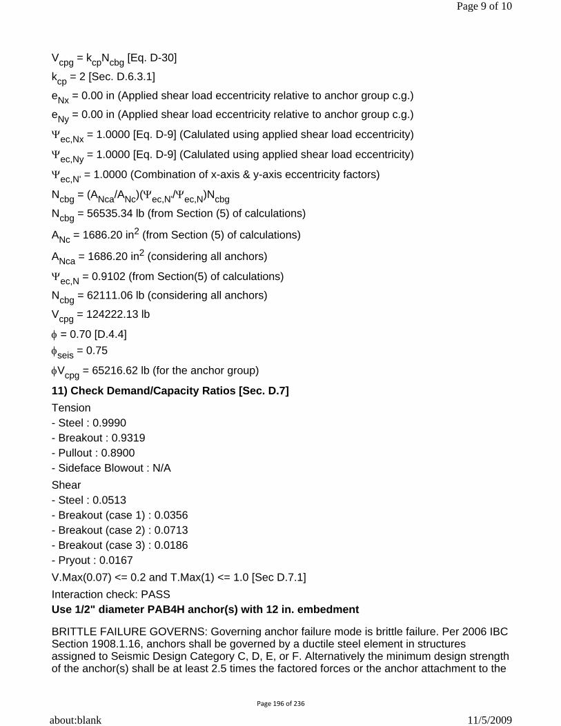
Vcpg = kcpNcbg [Eq. D-30]
kcp = 2 [Sec. D.6.3.1]
eNx = 0.00 in (Applied shear load eccentricity relative to anchor group c.g.)
eNy = 0.00 in (Applied shear load eccentricity relative to anchor group c.g.)
ec,Nx = 1.0000 [Eq. D-9] (Calulated using applied shear load eccentricity)
ec,Ny = 1.0000 [Eq. D-9] (Calulated using applied shear load eccentricity)
ec,N' = 1.0000 (Combination of x-axis & y-axis eccentricity factors)
Ncbg = (ANca/ANc)(ec,N'/ec,N)Ncbg
Ncbg = 56535.34 lb (from Section (5) of calculations)
ANc = 1686.20 in2 (from Section (5) of calculations)
ANca = 1686.20 in2 (considering all anchors)
ec,N = 0.9102 (from Section(5) of calculations)
Ncbg = 62111.06 lb (considering all anchors)
Vcpg = 124222.13 lb
= 0.70 [D.4.4]
seis = 0.75
Vcpg = 65216.62 lb (for the anchor group)
11) Check Demand/Capacity Ratios [Sec. D.7]
Tension - Steel : 0.9990- Breakout : 0.9319- Pullout : 0.8900- Sideface Blowout : N/A
Shear - Steel : 0.0513- Breakout (case 1) : 0.0356- Breakout (case 2) : 0.0713- Breakout (case 3) : 0.0186- Pryout : 0.0167
V.Max(0.07) <= 0.2 and T.Max(1) <= 1.0 [Sec D.7.1]
Interaction check: PASSUse 1/2" diameter PAB4H anchor(s) with 12 in. embedment
BRITTLE FAILURE GOVERNS: Governing anchor failure mode is brittle failure. Per 2006 IBC Section 1908.1.16, anchors shall be governed by a ductile steel element in structures assigned to Seismic Design Category C, D, E, or F. Alternatively the minimum design strength of the anchor(s) shall be at least 2.5 times the factored forces or the anchor attachment to the
Page 9 of 10
11/5/2009about:blank
Page 196 of 236

structure shall undergo ductile yielding at a load level less than the design strength of the anchor(s). Designer must exercise own judgement to determine if this design is suitable.
Page 10 of 10
11/5/2009about:blank
Page 197 of 236

Steel Base Plate Design ENERCALC, INC. 1983-2008, Ver: 6.0.221, N:40336License Owner : PIERCE ENGINEERINGLic. # : KW-06008640
File: Y:\@Shawn Pierce Engineering\09_Projects\Borzal Addition_02\Engineering\Design\melford borzall expansion.ec6Printed: 9 NOV 2009, 9:21AM
Description : Base Plate - Column at Intersection of Lines J.5 & 3
Title Block Line 1You can changes this areausing the "Settings" menu itemand then using the "Printing &Title Block" selection.Title Block Line 6
Title : Melford Borzall Expansion Job # 09.9-2/2
Project Desc.:Dsgnr: Shawn D. Pierce
Project Notes :
General Information
Material PropertiesAllowable Stress Design
Concrete Support f'c 2.50 ksiAllowable Bearing Fp per J8 3.188 ksi
1.0ABIF : Allowable Bearing Increase FactorASIF : Allowable Stress Increase Factor 1.0
: ASD Safety Factor. 2.50cSteel Plate Fy = 36.0 ksi
Assumed Bearing Area :Full Bearing
Calculations per 13th AISC & AISC Design Guide No. 1, 1990 by DeWolf & Ricker
=
AISC Design Method
Column Properties
1'-6"
2'-0
"
1'-0"
1'-0"X
Y
Steel Section : HSS6X6X3/16Depth
0.174 in
in in^23.986 Area
Support width along "X" 24.0 inLength along "Z' 18.0 in
Support Dimensions
Column assumed welded to base plate.
Width 6 inFlange Thickness
Ixx 22.3 in^422.3 in^4
Web Thickness in
Plate DimensionsN : Length 12.0 inB : Width 12.0 inThickness 0.750 in
Iyy
Y Y
X X
Column & Plate
Applied Loads
1.090 12.490
" P " = Gravity load, "+" sign is downward.
kk
P-Yk
kkkk
"+" Moments create higher soil pressure at +Z edge.
M-X
k-ftk-ftk-ftk-ftk-ftk-ft
k-ftV-Z
D : Dead Load .......L : Live .......Lr : Roof Live .........S : Snow ................W : Wind ................E : Earthquake ...............
k
H : Lateral Earth ......... k
kkkk
k
"+" Shears push plate towards +Z edge.
Anchor BoltsAnchor Bolt
6.1802.570
2.02.0
Anchor Bolt or Rod Description
Number of Bolts in each Row...................
k
Number of Bolt Rows........................
Max of Tension or Pullout Capacity...........Shear Capacity......................................... k
1.50 inEdge distance : bolt to plate...................
Row Spacing................................. 9.0 in
GOVERNING DESIGN LOAD CASE SUMMARYPlate Design Summary
Fp : Allowable :min( 0.85*f'c*sqrt(A2/A1), 1.7* f'c)*Ome
1.275 ksi
Bearing Stress OKfv : Actual ................................ 0.365 ksi
0.017Fv : Allowable = 0.60 * Fy / 1.5 (per G2) 21.557ksi
Stress Ratio .................Shear Stress OK
Stress Ratio .................
0.738
fu : Max. Plate Bearing Stress .... 0.364 ksi
Design Method Allowable Stress Design+D+0.70E+H
Governing Load Case Type Axial + Moment, Eccentricity <= L/6Design Plate Size 1'-0" x 1'-0" x 0 -3/4"Pa : Axial Load .... 0.000 kMa : Moment ........ 8.743 k-ft
Mu : Max. Moment ..................... 1.491 k-in
Governing Load Combination
fb : Max. Bending Stress ............... 15.905 ksiFb : Allowable :
Fy * ASIF / Omega 21.557 ksi
Bending Stress OKStress Ratio .................
0.286
Page 198 of 236

Steel Base Plate Design ENERCALC, INC. 1983-2008, Ver: 6.0.221, N:40336License Owner : PIERCE ENGINEERINGLic. # : KW-06008640
File: Y:\@Shawn Pierce Engineering\09_Projects\Borzal Addition_02\Engineering\Design\melford borzall expansion.ec6Printed: 9 NOV 2009, 9:21AM
Description : Base Plate - Column at Intersection of Lines J.5 & 3
Title Block Line 1You can changes this areausing the "Settings" menu itemand then using the "Printing &Title Block" selection.Title Block Line 6
Title : Melford Borzall Expansion Job # 09.9-2/2
Project Desc.:Dsgnr: Shawn D. Pierce
Project Notes :
Axial Load + Moment, Ecc. < L/6Load Comb. : +D+0.70E+H
LoadingPa : Axial Load .... 0.000 k
Bearing Stresses
A1 : Plate Area ............ 144.000 in^2
Fb : Allowable ................................ 21.557 ksi
A2 : Support Area ..................... 324.000 in^2
eA2/A1 ...................... 1.500
Mmax ................................. 1.491 k-in
Fp : Allowable ............................... 1.275 ksi
Distance for Moment Calculation
Ma : Moment ........ 8.743 k-ft
" m " ..................... 3.150 in
Eccentricity ........................ 0.000 in
" n " ..................... 3.600 in Stress Ratio .................... 0.738
fa : Max. Bearing Pressu 0.364 ksi
fb : Actual ................................ 15.905 ksi
Mmax1 = Fu * m^2 / 2 ...................... 1.491 k-inPlate Bending Stresses
Stress Ratio .................... 0.286
Mmax2 = Fu * n^2 / 2 ........................ 0.623 k-in
Shear Stressfv : Actual ................................ 0.365 ksi
Fv : Allowable .............................. 21.557 ksiStress Ratio ..................... 0.017
Axial Load + Moment, Ecc. < L/6Load Comb. : +D-0.70E+H
LoadingPa : Axial Load .... 0.000 k
Bearing Stresses
A1 : Plate Area ............ 144.000 in^2
Fb : Allowable ................................ 21.557 ksi
A2 : Support Area ..................... 324.000 in^2
eA2/A1 ...................... 1.500
Mmax ................................. 0.623 k-in
Fp : Allowable ............................... 1.275 ksi
Distance for Moment Calculation
Ma : Moment ........ 8.743 k-ft
" m " ..................... 3.150 in
Eccentricity ........................ 0.000 in
" n " ..................... 3.600 in Stress Ratio .................... 0.308
fa : Max. Bearing Pressu 0.364 ksi
fb : Actual ................................ 6.645 ksi
Mmax1 = Fu * m^2 / 2 ...................... 1.491 k-inPlate Bending Stresses
Stress Ratio .................... 0.286
Mmax2 = Fu * n^2 / 2 ........................ 0.623 k-in
Shear Stressfv : Actual ................................ 0.365 ksi
Fv : Allowable .............................. 21.557 ksiStress Ratio ..................... 0.017
Axial Load + Moment, Ecc. < L/6Load Comb. : +D+0.750Lr+0.750L+0.5250E+H
LoadingPa : Axial Load .... 0.000 k
Bearing Stresses
A1 : Plate Area ............ 144.000 in^2
Fb : Allowable ................................ 21.557 ksi
A2 : Support Area ..................... 324.000 in^2
eA2/A1 ...................... 1.500
Mmax ................................. 1.118 k-in
Fp : Allowable ............................... 1.275 ksi
Distance for Moment Calculation
Ma : Moment ........ 6.557 k-ft
" m " ..................... 3.150 in
Eccentricity ........................ 0.000 in
" n " ..................... 3.600 in Stress Ratio .................... 0.553
fa : Max. Bearing Pressu 0.273 ksi
fb : Actual ................................ 11.928 ksi
Mmax1 = Fu * m^2 / 2 ...................... 1.118 k-inPlate Bending Stresses
Stress Ratio .................... 0.214
Mmax2 = Fu * n^2 / 2 ........................ 0.467 k-in
Shear Stressfv : Actual ................................ 0.274 ksi
Fv : Allowable .............................. 21.557 ksiStress Ratio ..................... 0.013
Page 199 of 236

Steel Base Plate Design ENERCALC, INC. 1983-2008, Ver: 6.0.221, N:40336License Owner : PIERCE ENGINEERINGLic. # : KW-06008640
File: Y:\@Shawn Pierce Engineering\09_Projects\Borzal Addition_02\Engineering\Design\melford borzall expansion.ec6Printed: 9 NOV 2009, 9:21AM
Description : Base Plate - Column at Intersection of Lines J.5 & 3
Title Block Line 1You can changes this areausing the "Settings" menu itemand then using the "Printing &Title Block" selection.Title Block Line 6
Title : Melford Borzall Expansion Job # 09.9-2/2
Project Desc.:Dsgnr: Shawn D. Pierce
Project Notes :
Axial Load + Moment, Ecc. < L/6Load Comb. : +D+0.750Lr+0.750L-0.5250E+H
LoadingPa : Axial Load .... 0.000 k
Bearing Stresses
A1 : Plate Area ............ 144.000 in^2
Fb : Allowable ................................ 21.557 ksi
A2 : Support Area ..................... 324.000 in^2
eA2/A1 ...................... 1.500
Mmax ................................. 0.467 k-in
Fp : Allowable ............................... 1.275 ksi
Distance for Moment Calculation
Ma : Moment ........ 6.557 k-ft
" m " ..................... 3.150 in
Eccentricity ........................ 0.000 in
" n " ..................... 3.600 in Stress Ratio .................... 0.231
fa : Max. Bearing Pressu 0.273 ksi
fb : Actual ................................ 4.984 ksi
Mmax1 = Fu * m^2 / 2 ...................... 1.118 k-inPlate Bending Stresses
Stress Ratio .................... 0.214
Mmax2 = Fu * n^2 / 2 ........................ 0.467 k-in
Shear Stressfv : Actual ................................ 0.274 ksi
Fv : Allowable .............................. 21.557 ksiStress Ratio ..................... 0.013
Axial Load + Moment, Ecc. < L/6Load Comb. : +D+0.750L+0.750S+0.5250E+H
LoadingPa : Axial Load .... 0.000 k
Bearing Stresses
A1 : Plate Area ............ 144.000 in^2
Fb : Allowable ................................ 21.557 ksi
A2 : Support Area ..................... 324.000 in^2
eA2/A1 ...................... 1.500
Mmax ................................. 1.118 k-in
Fp : Allowable ............................... 1.275 ksi
Distance for Moment Calculation
Ma : Moment ........ 6.557 k-ft
" m " ..................... 3.150 in
Eccentricity ........................ 0.000 in
" n " ..................... 3.600 in Stress Ratio .................... 0.553
fa : Max. Bearing Pressu 0.273 ksi
fb : Actual ................................ 11.928 ksi
Mmax1 = Fu * m^2 / 2 ...................... 1.118 k-inPlate Bending Stresses
Stress Ratio .................... 0.214
Mmax2 = Fu * n^2 / 2 ........................ 0.467 k-in
Shear Stressfv : Actual ................................ 0.274 ksi
Fv : Allowable .............................. 21.557 ksiStress Ratio ..................... 0.013
Axial Load + Moment, Ecc. < L/6Load Comb. : +D+0.750L+0.750S-0.5250E+H
LoadingPa : Axial Load .... 0.000 k
Bearing Stresses
A1 : Plate Area ............ 144.000 in^2
Fb : Allowable ................................ 21.557 ksi
A2 : Support Area ..................... 324.000 in^2
eA2/A1 ...................... 1.500
Mmax ................................. 0.467 k-in
Fp : Allowable ............................... 1.275 ksi
Distance for Moment Calculation
Ma : Moment ........ 6.557 k-ft
" m " ..................... 3.150 in
Eccentricity ........................ 0.000 in
" n " ..................... 3.600 in Stress Ratio .................... 0.231
fa : Max. Bearing Pressu 0.273 ksi
fb : Actual ................................ 4.984 ksi
Mmax1 = Fu * m^2 / 2 ...................... 1.118 k-inPlate Bending Stresses
Stress Ratio .................... 0.214
Mmax2 = Fu * n^2 / 2 ........................ 0.467 k-in
Shear Stressfv : Actual ................................ 0.274 ksi
Fv : Allowable .............................. 21.557 ksiStress Ratio ..................... 0.013
Page 200 of 236

Steel Base Plate Design ENERCALC, INC. 1983-2008, Ver: 6.0.221, N:40336License Owner : PIERCE ENGINEERINGLic. # : KW-06008640
File: Y:\@Shawn Pierce Engineering\09_Projects\Borzal Addition_02\Engineering\Design\melford borzall expansion.ec6Printed: 9 NOV 2009, 9:21AM
Description : Base Plate - Column at Intersection of Lines J.5 & 3
Title Block Line 1You can changes this areausing the "Settings" menu itemand then using the "Printing &Title Block" selection.Title Block Line 6
Title : Melford Borzall Expansion Job # 09.9-2/2
Project Desc.:Dsgnr: Shawn D. Pierce
Project Notes :
Axial Load + Moment, Ecc. < L/6Load Comb. : +0.60D+0.70E+H
LoadingPa : Axial Load .... 0.000 k
Bearing Stresses
A1 : Plate Area ............ 144.000 in^2
Fb : Allowable ................................ 21.557 ksi
A2 : Support Area ..................... 324.000 in^2
eA2/A1 ...................... 1.500
Mmax ................................. 1.491 k-in
Fp : Allowable ............................... 1.275 ksi
Distance for Moment Calculation
Ma : Moment ........ 8.743 k-ft
" m " ..................... 3.150 in
Eccentricity ........................ 0.000 in
" n " ..................... 3.600 in Stress Ratio .................... 0.738
fa : Max. Bearing Pressu 0.364 ksi
fb : Actual ................................ 15.905 ksi
Mmax1 = Fu * m^2 / 2 ...................... 1.491 k-inPlate Bending Stresses
Stress Ratio .................... 0.286
Mmax2 = Fu * n^2 / 2 ........................ 0.623 k-in
Shear Stressfv : Actual ................................ 0.365 ksi
Fv : Allowable .............................. 21.557 ksiStress Ratio ..................... 0.017
Axial Load + Moment, Ecc. < L/6Load Comb. : +0.60D-0.70E+H
LoadingPa : Axial Load .... 0.000 k
Bearing Stresses
A1 : Plate Area ............ 144.000 in^2
Fb : Allowable ................................ 21.557 ksi
A2 : Support Area ..................... 324.000 in^2
eA2/A1 ...................... 1.500
Mmax ................................. 0.623 k-in
Fp : Allowable ............................... 1.275 ksi
Distance for Moment Calculation
Ma : Moment ........ 8.743 k-ft
" m " ..................... 3.150 in
Eccentricity ........................ 0.000 in
" n " ..................... 3.600 in Stress Ratio .................... 0.308
fa : Max. Bearing Pressu 0.364 ksi
fb : Actual ................................ 6.645 ksi
Mmax1 = Fu * m^2 / 2 ...................... 1.491 k-inPlate Bending Stresses
Stress Ratio .................... 0.286
Mmax2 = Fu * n^2 / 2 ........................ 0.623 k-in
Shear Stressfv : Actual ................................ 0.365 ksi
Fv : Allowable .............................. 21.557 ksiStress Ratio ..................... 0.017
Page 201 of 236

Page 202 of 236

Anchor Calculations
Anchor Designer for ACI 318 (Version 4.2.0.0)
Job Name : Tension Rebar Date/Time : 11/7/2009 6:59:19 PM
1) Input
Calculation Method : ACI 318 Appendix D For Cracked Concrete Calculation Type : Analysis
a) LayoutAnchor : 5/8" SET-XP Number of Anchors : 2Steel Grade: A615 GR. 60 Embedment Depth : 9 inBuilt-up Grout Pads : No
Anchor Layout Dimensions : cx1 : 6.75 in
cx2 : 26 in
cy1 : 3.5 in
cy2 : 20.5 in
sx1 : 9.75 in
b) Base Material
Concrete : Normal weight f'c : 2500.0 psi
Cracked Concrete : Yes c,V : 1.00
Condition : B tension and shear Fp : 1381.3
Page 1 of 10
11/7/2009about:blank
Page 203 of 236

psiThickness, h : 48 inSupplementary edge reinforcement : NoHole Condition : Dry ConcreteInspection : Continuous
Temperature Range : 1 (Maximum 110 oF short term and 75 oF long term temp.)
c) Factored LoadsLoad factor source : ACI 318 Section 9.2Nua : 5210 lb Vuax : 0 lb
Vuay : 0 lb Mux : 0 lb*ft
Muy : 0 lb*ft
ex : 0 in
ey : 0 in
Moderate/high seismic risk or intermediate/high design category : YesAnchor w/ sustained tension : NoAnchors only resist wind and/or seismic loads : YesApply entire shear load at front row for breakout : No d) Anchor ParametersFrom C-SAS-2009:
Anchor Model = SETXP do = 0.625 in
Category = 1 hef = 9 in
hmin = 12.125 in cac = 27 in
cmin = 1.75 in smin = 3 in
Ductile = Yes
2) Tension Force on Each Individual Anchor
Anchor #1 Nua1 = 2605.00 lb
Anchor #2 Nua2 = 2605.00 lb
Sum of Anchor Tension Nua = 5210.00 lb
e'Nx = 0.00 in
e'Ny = 0.00 in
3) Shear Force on Each Individual Anchor
Resultant shear forces in each anchor:Anchor #1 Vua1 = 0.00 lb (Vua1x = 0.00 lb , Vua1y = 0.00 lb )
Anchor #2 Vua2 = 0.00 lb (Vua2x = 0.00 lb , Vua2y = 0.00 lb )
Page 2 of 10
11/7/2009about:blank
Page 204 of 236
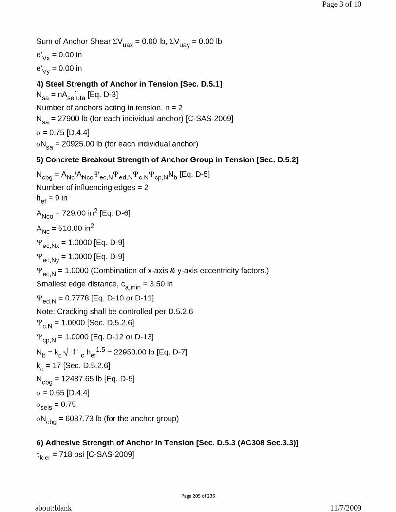
Sum of Anchor Shear Vuax = 0.00 lb, Vuay = 0.00 lb
e'Vx = 0.00 in
e'Vy = 0.00 in
4) Steel Strength of Anchor in Tension [Sec. D.5.1]Nsa = nAsefuta [Eq. D-3]
Number of anchors acting in tension, n = 2Nsa = 27900 lb (for each individual anchor) [C-SAS-2009]
= 0.75 [D.4.4]
Nsa = 20925.00 lb (for each individual anchor)
5) Concrete Breakout Strength of Anchor Group in Tension [Sec. D.5.2]
Ncbg = ANc/ANcoec,Ned,Nc,Ncp,NNb [Eq. D-5]
Number of influencing edges = 2hef = 9 in
ANco = 729.00 in2 [Eq. D-6]
ANc = 510.00 in2
ec,Nx = 1.0000 [Eq. D-9]
ec,Ny = 1.0000 [Eq. D-9]
ec,N = 1.0000 (Combination of x-axis & y-axis eccentricity factors.)
Smallest edge distance, ca,min = 3.50 in
ed,N = 0.7778 [Eq. D-10 or D-11]
Note: Cracking shall be controlled per D.5.2.6
c,N = 1.0000 [Sec. D.5.2.6]
cp,N = 1.0000 [Eq. D-12 or D-13]
Nb = kc f ' c hef1.5 = 22950.00 lb [Eq. D-7]
kc = 17 [Sec. D.5.2.6]
Ncbg = 12487.65 lb [Eq. D-5]
= 0.65 [D.4.4]
seis = 0.75
Ncbg = 6087.73 lb (for the anchor group)
6) Adhesive Strength of Anchor in Tension [Sec. D.5.3 (AC308 Sec.3.3)]
k,cr = 718 psi [C-SAS-2009]
Page 3 of 10
11/7/2009about:blank
Page 205 of 236

k,max,cr = kcr hef f'c/( do) [Eq. D-16i]
kcr = 17 [C-SAS-2009]
hef (unadjusted) = 9 in
k,max,cr = 1298.70 psi
Nao = k,cr dohef = 12688.11 lb [Eq. D-16f]
k,uncr = 2263.00 psi for use in [Eq. D-16d]
scr,Na = min[20do (k,uncr/1450) , 3hef] = 15.616 in [Eq. D-16d]
ccr,Na = scr,Na/2 = 7.808 in [Eq. D-16e]
Nag = ANa/ANaoed,Nag,Naec,Nap,NaNao [Eq. D-16b]
ANao = 243.86 in2 [Eq. D-16c]
ANa = 274.87 in2
ec,Nax = 1/(1+2e'Nx/scr,Na) = 1.0000 [Eq. D-16j]
ec,Nay = 1/(1+2e'Ny/scr,Na) = 1.0000 [Eq. D-16j]
ec,Na = 1.0000 (Combination of x-axis and y-axis eccentricity factors.)
Smallest edge distance, ca,min = 3.50 in
ed,Na = min[0.7+0.3ca,min/ccr,Na , 1.0] = 0.8345 [Eq. D-16m]
p,Na = 1.0000 [Sec. D.5.3.14]
g,Na = g,Nao+(s/scr,Na)0.5(1-g,Nao) [Eq. D-16g]
s = 10 in (largest spacing)
g,Nao = max{ n - [( n - 1)(k,cr/k,max,cr)1.5], 1.0} [Eq. D-16h]
g,Nao = 1.2439
g,Na = 1.0512
Nag = 12545.52 lb [Eq. D-16b]
= 0.65 [C-SAS-2009]
seis = 0.75
Nag = 6115.94 lb (for the anchor group)
7) Side Face Blowout of Anchor in Tension [Sec. D.5.4]
Concrete side face blowout strength is only calculated for headed anchors in tension close to an edge, ca1 < 0.4hef. Not applicable in this case.
8) Steel Strength of Anchor in Shear [Sec D.6.1] Vsa = 16740.00 lb (for each individual anchor)
Page 4 of 10
11/7/2009about:blank
Page 206 of 236
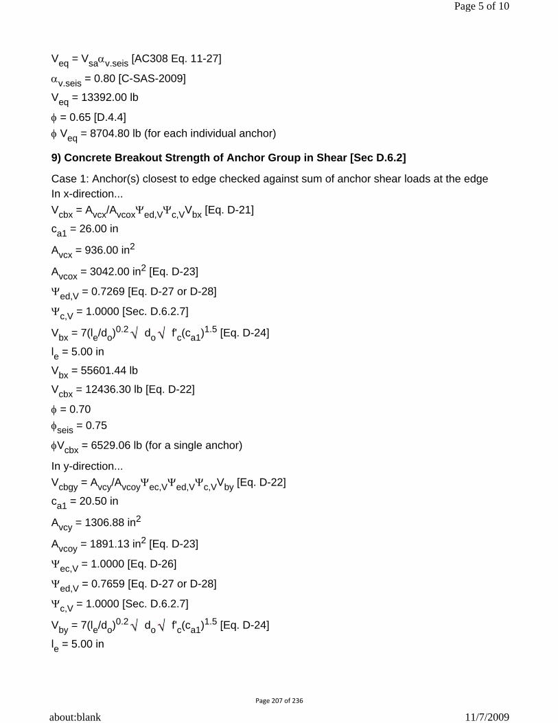
Veq = Vsav.seis [AC308 Eq. 11-27]
v.seis = 0.80 [C-SAS-2009]
Veq = 13392.00 lb
= 0.65 [D.4.4]
Veq = 8704.80 lb (for each individual anchor)
9) Concrete Breakout Strength of Anchor Group in Shear [Sec D.6.2]
Case 1: Anchor(s) closest to edge checked against sum of anchor shear loads at the edge In x-direction...
Vcbx = Avcx/Avcoxed,Vc,VVbx [Eq. D-21]
ca1 = 26.00 in
Avcx = 936.00 in2
Avcox = 3042.00 in2 [Eq. D-23]
ed,V = 0.7269 [Eq. D-27 or D-28]
c,V = 1.0000 [Sec. D.6.2.7]
Vbx = 7(le/do)0.2 do f'c(ca1)1.5 [Eq. D-24]
le = 5.00 in
Vbx = 55601.44 lb
Vcbx = 12436.30 lb [Eq. D-22]
= 0.70
seis = 0.75
Vcbx = 6529.06 lb (for a single anchor)
In y-direction...
Vcbgy = Avcy/Avcoyec,Ved,Vc,VVby [Eq. D-22]
ca1 = 20.50 in
Avcy = 1306.88 in2
Avcoy = 1891.13 in2 [Eq. D-23]
ec,V = 1.0000 [Eq. D-26]
ed,V = 0.7659 [Eq. D-27 or D-28]
c,V = 1.0000 [Sec. D.6.2.7]
Vby = 7(le/do)0.2 do f'c(ca1)1.5 [Eq. D-24]
le = 5.00 in
Page 5 of 10
11/7/2009about:blank
Page 207 of 236
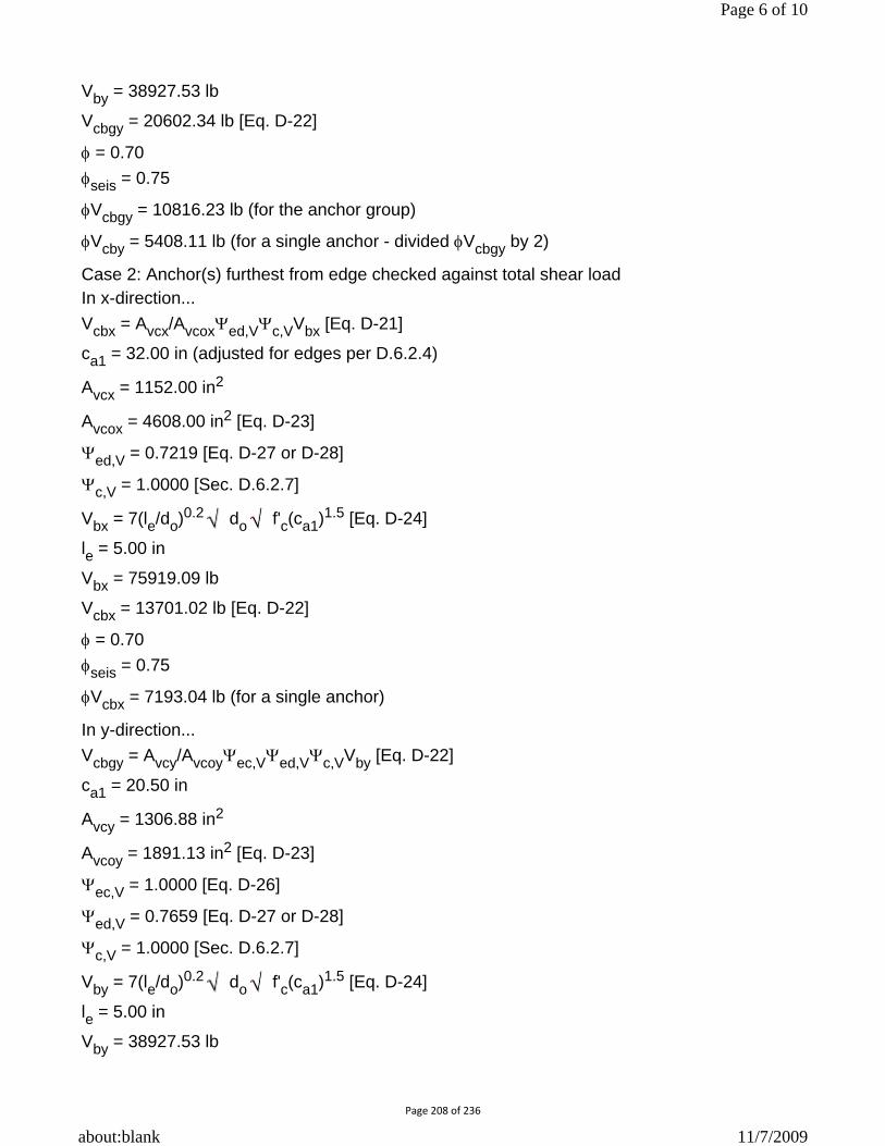
Vby = 38927.53 lb
Vcbgy = 20602.34 lb [Eq. D-22]
= 0.70
seis = 0.75
Vcbgy = 10816.23 lb (for the anchor group)
Vcby = 5408.11 lb (for a single anchor - divided Vcbgy by 2)
Case 2: Anchor(s) furthest from edge checked against total shear load In x-direction...
Vcbx = Avcx/Avcoxed,Vc,VVbx [Eq. D-21]
ca1 = 32.00 in (adjusted for edges per D.6.2.4)
Avcx = 1152.00 in2
Avcox = 4608.00 in2 [Eq. D-23]
ed,V = 0.7219 [Eq. D-27 or D-28]
c,V = 1.0000 [Sec. D.6.2.7]
Vbx = 7(le/do)0.2 do f'c(ca1)1.5 [Eq. D-24]
le = 5.00 in
Vbx = 75919.09 lb
Vcbx = 13701.02 lb [Eq. D-22]
= 0.70
seis = 0.75
Vcbx = 7193.04 lb (for a single anchor)
In y-direction...
Vcbgy = Avcy/Avcoyec,Ved,Vc,VVby [Eq. D-22]
ca1 = 20.50 in
Avcy = 1306.88 in2
Avcoy = 1891.13 in2 [Eq. D-23]
ec,V = 1.0000 [Eq. D-26]
ed,V = 0.7659 [Eq. D-27 or D-28]
c,V = 1.0000 [Sec. D.6.2.7]
Vby = 7(le/do)0.2 do f'c(ca1)1.5 [Eq. D-24]
le = 5.00 in
Vby = 38927.53 lb
Page 6 of 10
11/7/2009about:blank
Page 208 of 236
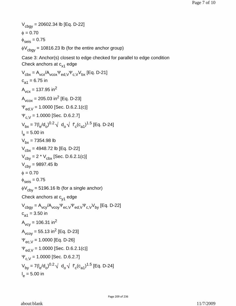
Vcbgy = 20602.34 lb [Eq. D-22]
= 0.70
seis = 0.75
Vcbgy = 10816.23 lb (for the entire anchor group)
Case 3: Anchor(s) closest to edge checked for parallel to edge condition Check anchors at cx1 edge
Vcbx = Avcx/Avcoxed,Vc,VVbx [Eq. D-21]
ca1 = 6.75 in
Avcx = 137.95 in2
Avcox = 205.03 in2 [Eq. D-23]
ed,V = 1.0000 [Sec. D.6.2.1(c)]
c,V = 1.0000 [Sec. D.6.2.7]
Vbx = 7(le/do)0.2 do f'c(ca1)1.5 [Eq. D-24]
le = 5.00 in
Vbx = 7354.98 lb
Vcbx = 4948.72 lb [Eq. D-22]
Vcby = 2 * Vcbx [Sec. D.6.2.1(c)]
Vcby = 9897.45 lb
= 0.70
seis = 0.75
Vcby = 5196.16 lb (for a single anchor)
Check anchors at cy1 edge
Vcbgy = Avcy/Avcoyec,Ved,Vc,VVby [Eq. D-22]
ca1 = 3.50 in
Avcy = 106.31 in2
Avcoy = 55.13 in2 [Eq. D-23]
ec,V = 1.0000 [Eq. D-26]
ed,V = 1.0000 [Sec. D.6.2.1(c)]
c,V = 1.0000 [Sec. D.6.2.7]
Vby = 7(le/do)0.2 do f'c(ca1)1.5 [Eq. D-24]
le = 5.00 in
Page 7 of 10
11/7/2009about:blank
Page 209 of 236

Vby = 2746.17 lb
Vcbgy = 5296.19 lb [Eq. D-22]
Vcbgx = 2 * Vcbgy [Sec. D.6.2.1(c)]
Vcbgx = 10592.39 lb
= 0.70
seis = 0.75
Vcbgx = 5561.00 lb (for the anchor group)
Check anchors at cx2 edge
Vcbx = Avcx/Avcoxed,Vc,VVbx [Eq. D-21]
ca1 = 26.00 in
Avcx = 936.00 in2
Avcox = 3042.00 in2 [Eq. D-23]
ed,V = 1.0000 [Eq. D-27 or D-28] [Sec. D.6.2.1(c)]
c,V = 1.0000 [Sec. D.6.2.7]
Vbx = 7(le/do)0.2 do f'c(ca1)1.5 [Eq. D-24]
le = 5.00 in
Vbx = 55601.44 lb
Vcbx = 17108.14 lb [Eq. D-22]
Vcby = 2 * Vcbx [Sec. D.6.2.1(c)]
Vcby = 34216.27 lb
= 0.70
seis = 0.75
Vcby = 17963.54 lb (for a single anchor)
Check anchors at cy2 edge
Vcbgy = Avcy/Avcoyec,Ved,Vc,VVby [Eq. D-22]
ca1 = 20.50 in
Avcy = 1306.88 in2
Avcoy = 1891.13 in2 [Eq. D-23]
ec,V = 1.0000 [Eq. D-26]
ed,V = 1.0000 [Sec. D.6.2.1(c)]
c,V = 1.0000 [Sec. D.6.2.7]
Page 8 of 10
11/7/2009about:blank
Page 210 of 236

Vby = 7(le/do)0.2 do f'c(ca1)1.5 [Eq. D-24]
le = 5.00 in
Vby = 38927.53 lb
Vcbgy = 26901.14 lb [Eq. D-22]
Vcbgx = 2 * Vcbgy [Sec. D.6.2.1(c)]
Vcbgx = 53802.28 lb
= 0.70
seis = 0.75
Vcbgx = 28246.20 lb (for the anchor group)
10) Concrete Pryout Strength of Anchor Group in Shear [Sec. D.6.3]
Vcpg = min[kcpNag,kcpNcbg] [Eq. D-30b]
kcp = 2 [Sec. D.6.3.2]
eNx = 0.00 in (Applied shear load eccentricity relative to anchor group c.g.)
eNy = 0.00 in (Applied shear load eccentricity relative to anchor group c.g.)
ec,Nx = 1.0000 [Eq. D-9] (Calulated using applied shear load eccentricity)
ec,Ny = 1.0000 [Eq. D-9] (Calulated using applied shear load eccentricity)
ec,N' = 1.0000 (Combination of x-axis & y-axis eccentricity factors)
Nag = (ANaa/ANa)(ec,N'/ec,Na)Nag
Nag = 12545.52 lb (from Section (6) of calculations)
ANa = 274.87 in2 (from Section (6) of calculations)
ANaa = 274.87 in2 (considering all anchors)
ec,Na = 1.0000 (from Section(6) of calculations)
Nag = 12545.52 lb (considering all anchors)
Ncbg = (ANca/ANc)(ec,N'/ec,N)Ncbg
Ncbg = 12487.65 lb (from Section (5) of calculations)
ANc = 510.00 in2 (from Section (5) of calculations)
ANca = 510.00 in2 (considering all anchors)
ec,N = 1.0000 (from Section(5) of calculations)
Ncbg = 12487.65 lb (considering all anchors)
Vcpg = 24975.31 lb
= 0.70 [D.4.4]
seis = 0.75
Page 9 of 10
11/7/2009about:blank
Page 211 of 236

Vcpg = 13112.04 lb (for the anchor group)
11) Check Demand/Capacity Ratios [Sec. D.7]
Tension - Steel : 0.1245- Breakout : 0.8558- Adhesive : 0.8519- Sideface Blowout : N/A
Shear - Steel : 0.0000- Breakout (case 1) : 0.0000- Breakout (case 2) : 0.0000- Breakout (case 3) : 0.0000- Pryout : 0.0000
V.Max(0) <= 0.2 and T.Max(0.86) <= 1.0 [Sec D.7.1]
Interaction check: PASSUse 5/8" diameter A615 GR. 60 SET-XP anchor(s) with 9 in. embedment
BRITTLE FAILURE GOVERNS: Governing anchor failure mode is brittle failure. Per 2006 IBC Section 1908.1.16, anchors shall be governed by a ductile steel element in structures assigned to Seismic Design Category C, D, E, or F. Alternatively the minimum design strength of the anchor(s) shall be at least 2.5 times the factored forces or the anchor attachment to the structure shall undergo ductile yielding at a load level less than the design strength of the anchor(s). Designer must exercise own judgement to determine if this design is suitable.
Page 10 of 10
11/7/2009about:blank
Page 212 of 236

Page 213 of 236
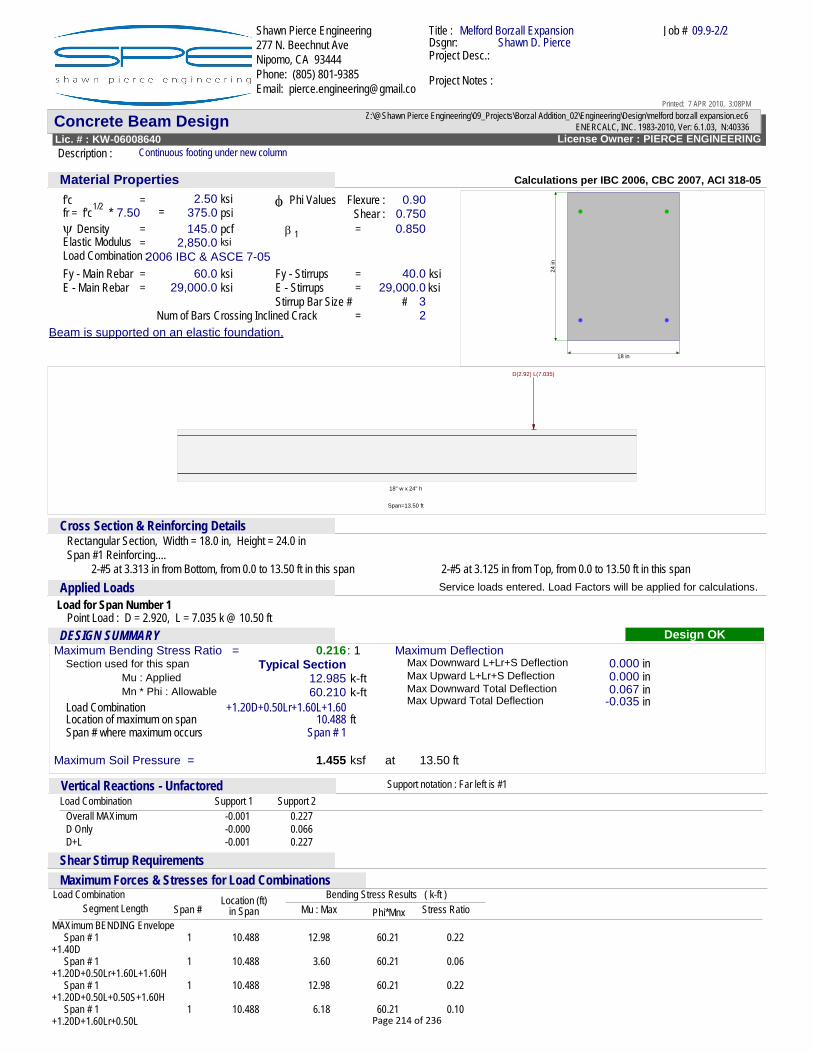
Concrete Beam Design ENERCALC, INC. 1983-2010, Ver: 6.1.03, N:40336License Owner : PIERCE ENGINEERINGLic. # : KW-06008640
File: Z:\@Shawn Pierce Engineering\09_Projects\Borzal Addition_02\Engineering\Design\melford borzall expansion.ec6Printed: 7 APR 2010, 3:08PM
Description : Continuous footing under new column
Shawn Pierce Engineering277 N. Beechnut AveNipomo, CA 93444Phone: (805) 801-9385Email: [email protected]
Title : Melford Borzall Expansion Job # 09.9-2/2
Project Desc.:Dsgnr: Shawn D. Pierce
Project Notes :
Material Properties Calculations per IBC 2006, CBC 2007, ACI 318-05
2.507.50
145.0Elastic Modulus 2,850.0 ksi
1
=60.0
29,000.040.0
29,000.03
Beam is supported on an elastic foundation,
2
= 0.900.750
f'c ksi
Fy - Main Rebar ksi
Density
1/2
=
fr = f'c * 375.0pcf
E - Main Rebar ksi
psi
=
Fy - Stirrups ksi
===
E - Stirrups ksi
18 in
24
in
0.850
===
Shear :
Stirrup Bar Size #Num of Bars Crossing Inclined Crack
Phi Values Flexure :
#
Load Combination :2006 IBC & ASCE 7-05
18" w x 24" h
Span=13.50 ft
D(2.92) L(7.035)
.Cross Section & Reinforcing DetailsRectangular Section, Width = 18.0 in, Height = 24.0 inSpan #1 Reinforcing.... 2-#5 at 3.313 in from Bottom, from 0.0 to 13.50 ft in this span 2-#5 at 3.125 in from Top, from 0.0 to 13.50 ft in this span
.Service loads entered. Load Factors will be applied for calculations.Applied LoadsLoad for Span Number 1
Point Load : D = 2.920, L = 7.035 k @ 10.50 ft.Design OKDESIGN SUMMARY
Maximum Bending Stress Ratio = 0.216 : 1
Load Combination +1.20D+0.50Lr+1.60L+1.60
Span # where maximum occurs Span # 1
Maximum Soil Pressure = 1.455 ksf at 13.50 ft
Location of maximum on span 10.488 ft
Mn * Phi : Allowable 60.210 k-ft
Typical SectionSection used for this spanMu : Applied 12.985 k-ft
Maximum DeflectionMax Downward L+Lr+S Deflection 0.000 inMax Upward L+Lr+S Deflection 0.000 inMax Downward Total Deflection 0.067 inMax Upward Total Deflection -0.035 in
.Load Combination Support 1 Support 2Vertical Reactions - Unfactored Support notation : Far left is #1
Overall MAXimum -0.001 0.227D Only -0.000 0.066D+L -0.001 0.227
.Shear Stirrup Requirements
.Maximum Forces & Stresses for Load Combinations
Span #Bending Stress Results ( k-ft )Location (ft)Load Combination
Mu : Max Stress RatioSegment Length Phi*Mnxin SpanMAXimum BENDING Envelope Span # 1 1 10.488 12.98 60.21 0.22+1.40D Span # 1 1 10.488 3.60 60.21 0.06+1.20D+0.50Lr+1.60L+1.60H Span # 1 1 10.488 12.98 60.21 0.22+1.20D+0.50L+0.50S+1.60H Span # 1 1 10.488 6.18 60.21 0.10+1.20D+1.60Lr+0.50L Page 214 of 236

Concrete Beam Design ENERCALC, INC. 1983-2010, Ver: 6.1.03, N:40336License Owner : PIERCE ENGINEERINGLic. # : KW-06008640
File: Z:\@Shawn Pierce Engineering\09_Projects\Borzal Addition_02\Engineering\Design\melford borzall expansion.ec6Printed: 7 APR 2010, 3:08PM
Description : Continuous footing under new column
Shawn Pierce Engineering277 N. Beechnut AveNipomo, CA 93444Phone: (805) 801-9385Email: [email protected]
Title : Melford Borzall Expansion Job # 09.9-2/2
Project Desc.:Dsgnr: Shawn D. Pierce
Project Notes :
Span #Bending Stress Results ( k-ft )Location (ft)Load Combination
Mu : Max Stress RatioSegment Length Phi*Mnxin Span Span # 1 1 10.488 6.18 60.21 0.10+1.20D+1.60Lr+0.50L+0.80W Span # 1 1 10.488 6.18 60.21 0.10+1.20D+0.50L+1.60S Span # 1 1 10.488 6.18 60.21 0.10+1.20D+0.50L+1.60S+0.80W Span # 1 1 10.488 6.18 60.21 0.10+1.20D+0.50Lr+0.50L+1.60W Span # 1 1 10.488 6.18 60.21 0.10+1.20D+0.50L+0.50S+1.60W Span # 1 1 10.488 6.18 60.21 0.10+1.20D+0.50L+0.20S+E Span # 1 1 10.488 6.18 60.21 0.10+0.90D+1.60W+1.60H Span # 1 1 10.488 2.31 60.21 0.04+0.90D+E+1.60H Span # 1 1 10.488 2.31 60.21 0.04
.Location in SpanLoad CombinationMax. "-" Defl Location in SpanLoad Combination Span Max. "+" Defl
Overall Maximum Deflections - Unfactored Loads
Span 1Span 1 1 0.0674 13.500 -0.0352 0.000
Page 215 of 236
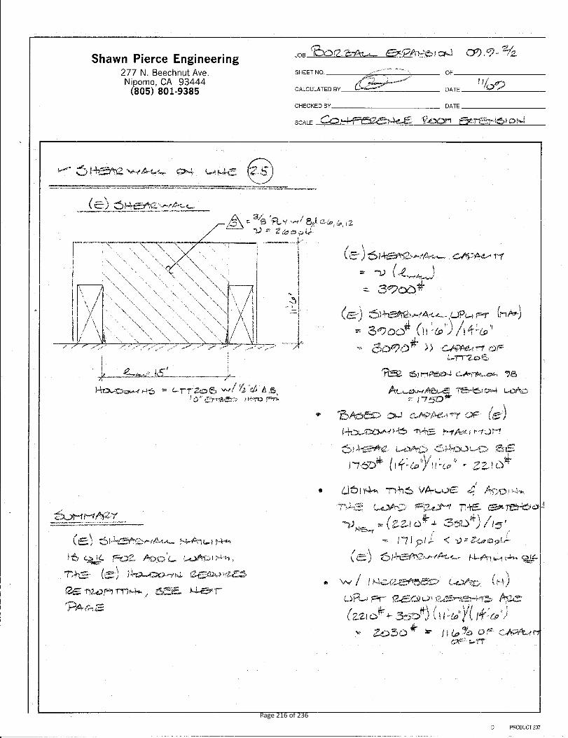
Page 216 of 236

Page 217 of 236

Anchor Calculations
Anchor Designer for ACI 318 (Version 4.2.0.0)
Job Name : Borzall - 5/8"Dia Anchor Date/Time : 11/9/2009 6:51:40 AM
1) Input
Calculation Method : ACI 318 Appendix D For Cracked Concrete Calculation Type : Analysis
a) LayoutAnchor : 5/8" SET-XP Number of Anchors : 1Steel Grade: A307 GR. C Embedment Depth : 5 inBuilt-up Grout Pads : No
Anchor Layout Dimensions : cx1 : 6 in
cx2 : 6 in
cy1 : 60 in
cy2 : 60 in
b) Base Material
Concrete : Normal weight f'c : 2500.0 psi
Cracked Concrete : Yes c,V : 1.00
Condition : A tension, B shearFp : 1381.3
psi
Page 1 of 5
11/9/2009about:blank
Page 218 of 236

Thickness, h : 18 inSupplementary edge reinforcement : NoHole Condition : Dry ConcreteInspection : Continuous
Temperature Range : 1 (Maximum 110 oF short term and 75 oF long term temp.)
c) Factored LoadsLoad factor source : ACI 318 Section 9.2Nua : 2030 lb Vuax : 0 lb
Vuay : 0 lb Mux : 0 lb*ft
Muy : 0 lb*ft
ex : 0 in
ey : 0 in
Moderate/high seismic risk or intermediate/high design category : YesAnchor w/ sustained tension : NoAnchors only resist wind and/or seismic loads : YesApply entire shear load at front row for breakout : No d) Anchor ParametersFrom C-SAS-2009:
Anchor Model = SETXP do = 0.625 in
Category = 1 hef = 5 in
hmin = 8.125 in cac = 15 in
cmin = 1.75 in smin = 3 in
Ductile = Yes
2) Tension Force on Each Individual Anchor
Anchor #1 Nua1 = 2030.00 lb
Sum of Anchor Tension Nua = 2030.00 lb
e'Nx = 0.00 in
e'Ny = 0.00 in
3) Shear Force on Each Individual Anchor
Resultant shear forces in each anchor:Anchor #1 Vua1 = 0.00 lb (Vua1x = 0.00 lb , Vua1y = 0.00 lb )
Sum of Anchor Shear Vuax = 0.00 lb, Vuay = 0.00 lb
e'Vx = 0.00 in
e'Vy = 0.00 in
Page 2 of 5
11/9/2009about:blank
Page 219 of 236
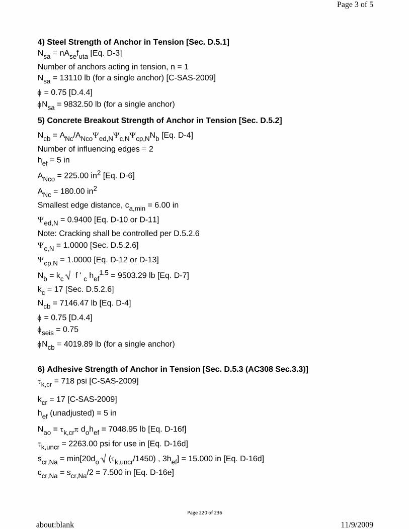
4) Steel Strength of Anchor in Tension [Sec. D.5.1]Nsa = nAsefuta [Eq. D-3]
Number of anchors acting in tension, n = 1Nsa = 13110 lb (for a single anchor) [C-SAS-2009]
= 0.75 [D.4.4]
Nsa = 9832.50 lb (for a single anchor)
5) Concrete Breakout Strength of Anchor in Tension [Sec. D.5.2]
Ncb = ANc/ANcoed,Nc,Ncp,NNb [Eq. D-4]
Number of influencing edges = 2hef = 5 in
ANco = 225.00 in2 [Eq. D-6]
ANc = 180.00 in2
Smallest edge distance, ca,min = 6.00 in
ed,N = 0.9400 [Eq. D-10 or D-11]
Note: Cracking shall be controlled per D.5.2.6
c,N = 1.0000 [Sec. D.5.2.6]
cp,N = 1.0000 [Eq. D-12 or D-13]
Nb = kc f ' c hef1.5 = 9503.29 lb [Eq. D-7]
kc = 17 [Sec. D.5.2.6]
Ncb = 7146.47 lb [Eq. D-4]
= 0.75 [D.4.4]
seis = 0.75
Ncb = 4019.89 lb (for a single anchor)
6) Adhesive Strength of Anchor in Tension [Sec. D.5.3 (AC308 Sec.3.3)]
k,cr = 718 psi [C-SAS-2009]
kcr = 17 [C-SAS-2009]
hef (unadjusted) = 5 in
Nao = k,cr dohef = 7048.95 lb [Eq. D-16f]
k,uncr = 2263.00 psi for use in [Eq. D-16d]
scr,Na = min[20do (k,uncr/1450) , 3hef] = 15.000 in [Eq. D-16d]
ccr,Na = scr,Na/2 = 7.500 in [Eq. D-16e]
Page 3 of 5
11/9/2009about:blank
Page 220 of 236

Na = ANa/ANaoed,Nap,NaNao [Eq. D-16a]
ANao = 225.00 in2 [Eq. D-16c]
ANa = 180.00 in2
Smallest edge distance, ca,min = 6.00 in
ed,Na = min[0.7+0.3ca,min/ccr,Na , 1.0] = 0.9400 [Eq. D-16m]
p,Na = 1.0000 [Sec. D.5.3.14]
Na = 5300.81 lb [Eq. D-16a]
= 0.65 [C-SAS-2009]
seis = 0.75
Na = 2584.14 lb (for a single anchor)
7) Side Face Blowout of Anchor in Tension [Sec. D.5.4]
Concrete side face blowout strength is only calculated for headed anchors in tension close to an edge, ca1 < 0.4hef. Not applicable in this case.
8) Steel Strength of Anchor in Shear [Sec D.6.1] Vsa = 7865.00 lb (for a single anchor)
Veq = Vsav.seis [AC308 Eq. 11-27]
v.seis = 0.71 [C-SAS-2009]
Veq = 5584.15 lb
= 0.65 [D.4.4]
Veq = 3629.70 lb (for a single anchor)
9) Concrete Breakout Strength of Anchor in Shear [Sec D.6.2]
Concrete breakout strength has not been evaluated against applied shear load(s) per user option. Refer to Section D.4.2.1 of ACI 318 for conditions where calculations of the concrete breakout strength may not be required.
10) Concrete Pryout Strength of Anchor in Shear [Sec. D.6.3]
Vcp = min[kcpNa,kcpNcb] [Eq. D-30a]
kcp = 2 [Sec. D.6.3.2]
Na = 5300.81 lb (from Section (6) of calculations)
Ncb = 7146.47 lb (from Section (5) of calculations)
Vcp = 10601.62 lb
= 0.70 [D.4.4]
seis = 0.75
Page 4 of 5
11/9/2009about:blank
Page 221 of 236

Vcp = 5565.85 lb (for a single anchor)
11) Check Demand/Capacity Ratios [Sec. D.7]
Tension - Steel : 0.2065- Breakout : 0.5050- Adhesive : 0.7856- Sideface Blowout : N/A
Shear - Steel : 0.0000- Breakout : N/A- Pryout : 0.0000
V.Max(0) <= 0.2 and T.Max(0.79) <= 1.0 [Sec D.7.1]
Interaction check: PASSUse 5/8" diameter A307 GR. C SET-XP anchor(s) with 5 in. embedment
BRITTLE FAILURE GOVERNS: Governing anchor failure mode is brittle failure. Per 2006 IBC Section 1908.1.16, anchors shall be governed by a ductile steel element in structures assigned to Seismic Design Category C, D, E, or F. Alternatively the minimum design strength of the anchor(s) shall be at least 2.5 times the factored forces or the anchor attachment to the structure shall undergo ductile yielding at a load level less than the design strength of the anchor(s). Designer must exercise own judgement to determine if this design is suitable.
Page 5 of 5
11/9/2009about:blank
Page 222 of 236

Page 223 of 236

APPENDIX
Page 224 of 236

TE
CH
NIC
AL
BU
LL
ET
IN
June
200
8 B
ulle
tin T
B-7
03
See
iLev
el® T
rus
Jois
t® T
imbe
rStr
and®
LSL
Sta
ir St
ringe
r Des
ign
Gui
de
TJ-8
003
for M
ore
Info
rmat
ion
and
Inst
alla
tion
Det
ails
Wey
erh
aeu
ser,
iLe
vel®
, T
imbe
rStr
and
® a
nd T
rus
Jois
t® a
re r
egi
ste
red
tra
dem
ark
s of
We
yerh
aeu
ser.
© 2
008
We
yerh
aeu
ser
Com
pan
y. A
ll rig
hts
re
serv
ed
.
CO
NTA
CT
US ▪ 1
.888
.iLev
el8
(1.8
88.4
53.8
358)
▪ w
ww
.iLev
el.c
om
Trus
Joi
st® 1
¾"
1.55
E Ti
mbe
rStr
and®
LSL
Sta
ir St
ringe
r Tab
les
Max
imum
Str
inge
r Run
– 4
0 ps
f Liv
e Lo
ad a
nd 1
2 ps
f Dea
d Lo
ad
36"
Trea
d W
idth
36
" Tr
ead
Wid
th
42"
Trea
d W
idth
44
" Tr
ead
Wid
th
48"
Trea
d W
idth
2
Strin
gers
3
Strin
gers
3
Strin
gers
3
Strin
gers
3
Strin
gers
1¾
" 1.
55E
LSL
Stai
r Str
inge
r Dep
th
With
2x4
R
einf
orce
men
t W
ith 2
x4
Rei
nfor
cem
ent
With
2x4
R
einf
orce
men
t W
ith 2
x4
Rei
nfor
cem
ent
With
2x4
R
einf
orce
men
t 9.
5"
7'-6
" 8'
-4"
7'-6
" 7'
-6"
7'-6
"
11⅞
" 10
'-10
" 12
'-6"
12'-6
" 11
'-8"
11'-8
"
14"
14'-2
" 14
'-2"
14'-2
" 14
'-2"
14'-2
"
Max
imum
Str
inge
r Run
– 1
00 p
sf L
ive
Load
and
12
psf D
ead
Load
36
" Tr
ead
Wid
th
36"
Trea
d W
idth
42
" Tr
ead
Wid
th
44"
Trea
d W
idth
48
" Tr
ead
Wid
th
2 St
ringe
rs
3 St
ringe
rs
3 St
ringe
rs
3 St
ringe
rs
3 St
ringe
rs
1¾"
1.55
E LS
L St
air S
trin
ger D
epth
W
ith 2
x4
Rei
nfor
cem
ent
With
2x4
R
einf
orce
men
t W
ith 2
x4
Rei
nfor
cem
ent
With
2x4
R
einf
orce
men
t W
ith 2
x4
Rei
nfor
cem
ent
9.5"
5'
-0"
5'-1
0"
5'-1
0"
5'-1
0"
5'-0
"
11⅞
" 8'
-4"
9'-2
" 9'
-2"
8'-4
" 8'
-4"
14"
10'-0
" 11
'-8"
10'-1
0"
10'-1
0"
10'-1
0"
Mul
tiple
Spa
n
Sim
ple
Span
Gen
eral
Gui
delin
es fo
r Cal
cula
ting
Step
Ris
e an
d R
un
T
he r
ise
times
the
run
sho
uld
equ
al a
ppro
xim
atel
y 75
".
T
wo
times
the
rise
plus
one
run
sho
uld
equ
al a
ppr
oxi
mat
ely
25"
.
Ris
e pl
us r
un s
hou
ld b
e 17
" to
18"
. G
ener
al N
otes
Max
imum
str
inge
r ru
ns s
ho
wn
are
valid
for
U.S
cod
es (
wo
rkin
g st
ress
) or
C
anad
ian
code
s (L
imit
Sta
te D
esig
n). L
oads
sho
wn
are
unfa
ctor
ed.
D
efle
ctio
n cr
iteria
of L
/360
live
load
and
L/2
40
tota
l loa
d.
S
tair
wa
y as
sem
bly
is u
nsta
ble
until
trea
ds a
re in
stal
led.
Use
sub
floor
adh
esiv
e to
impr
ove
the
stai
r p
erfo
rman
ce a
nd
min
imiz
e sq
uea
ks.
T
able
s ba
sed
on 7
¾"
ma
xim
um r
ise
and
10"
min
imum
ru
n. L
ocal
co
des
ma
y be
mor
e re
stric
tive.
Max
imum
ris
e be
twe
en fl
oor
s or
lan
din
gs p
erm
itted
by
code
is 1
2'-0
".
K
eep
mat
eria
ls d
ry.
Add
va
por
barr
ier
at b
otto
m o
f sta
ir st
ringe
r if
it is
in c
ont
act
with
con
cret
e
The
atta
chm
ent
deta
il sh
ow
n is
a s
ugge
stio
n on
ly;
alte
rnat
e de
tails
are
pos
sibl
e. R
espo
nsib
ility
re
mai
ns w
ith th
e pr
ojec
t des
igne
r or
en
gine
er o
f rec
ord.
Low
End
Atta
chm
ent –
40
psf L
ive
Load
12
psf D
ead
Load
F
or a
ssis
tanc
e w
ith lo
adin
g co
nditi
ons
and
stai
r co
nfig
urat
ions
not
sho
wn
,
cont
act
your
iLev
el r
epr
ese
ntat
ive.
Page 225 of 236
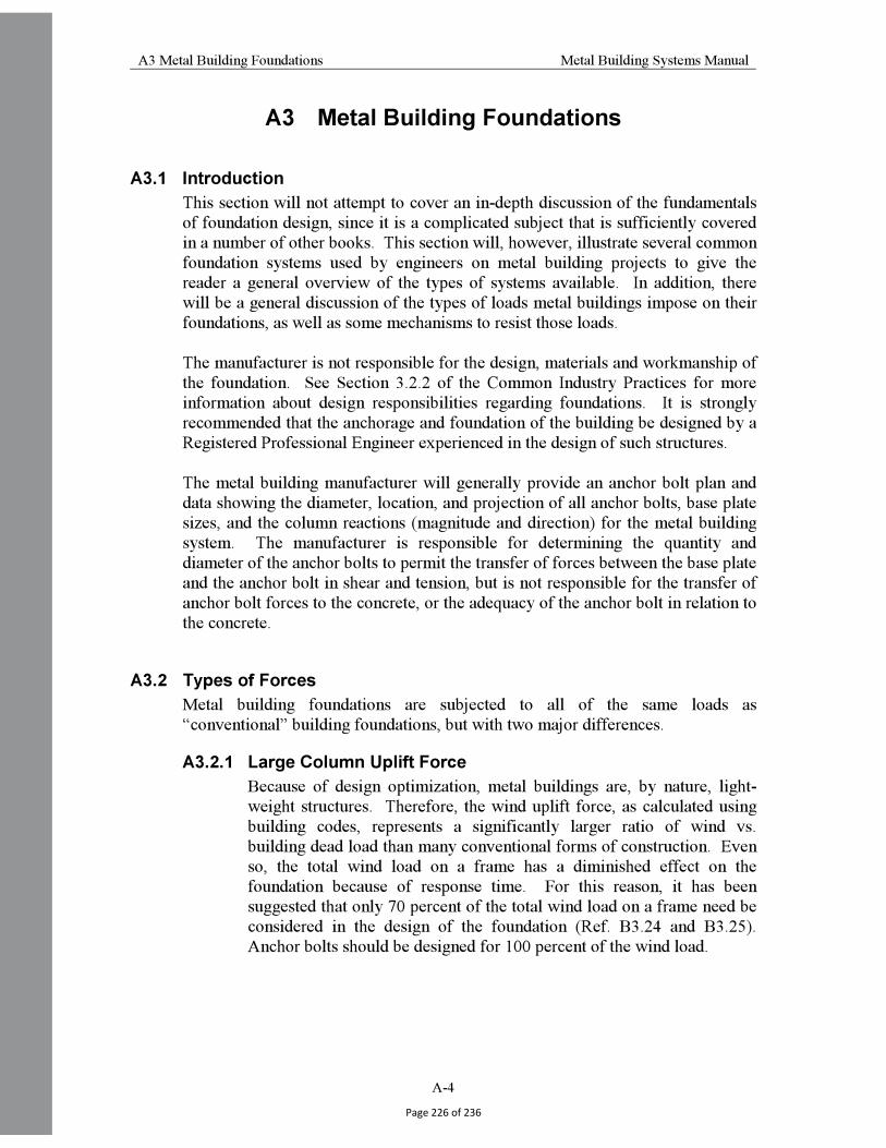
A3 Metal Building Foundations Metal Building Systems Manual
A-4
A3 Metal Building Foundations
A3.1 Introduction
This section will not attempt to cover an in-depth discussion of the fundamentals
of foundation design, since it is a complicated subject that is sufficiently covered
in a number of other books. This section will, however, illustrate several common
foundation systems used by engineers on metal building projects to give the
reader a general overview of the types of systems available. In addition, there
will be a general discussion of the types of loads metal buildings impose on their
foundations, as well as some mechanisms to resist those loads.
The manufacturer is not responsible for the design, materials and workmanship of
the foundation. See Section 3.2.2 of the Common Industry Practices for more
information about design responsibilities regarding foundations. It is strongly
recommended that the anchorage and foundation of the building be designed by a
Registered Professional Engineer experienced in the design of such structures.
The metal building manufacturer will generally provide an anchor bolt plan and
data showing the diameter, location, and projection of all anchor bolts, base plate
sizes, and the column reactions (magnitude and direction) for the metal building
system. The manufacturer is responsible for determining the quantity and
diameter of the anchor bolts to permit the transfer of forces between the base plate
and the anchor bolt in shear and tension, but is not responsible for the transfer of
anchor bolt forces to the concrete, or the adequacy of the anchor bolt in relation to
the concrete.
A3.2 Types of Forces
Metal building foundations are subjected to all of the same loads as
“conventional” building foundations, but with two major differences.
A3.2.1 Large Column Uplift Force
Because of design optimization, metal buildings are, by nature, light-
weight structures. Therefore, the wind uplift force, as calculated using
building codes, represents a significantly larger ratio of wind vs.
building dead load than many conventional forms of construction. Even
so, the total wind load on a frame has a diminished effect on the
foundation because of response time. For this reason, it has been
suggested that only 70 percent of the total wind load on a frame need be
considered in the design of the foundation (Ref. B3.24 and B3.25).
Anchor bolts should be designed for 100 percent of the wind load.
Page 226 of 236

Metal Building Systems Manual A3 Metal Building Foundations
A-5
A3.2.2 Horizontal Thrust Force
Many metal buildings utilize rigid frames, which can generate a
substantial horizontal “thrust” force from gravity loads. This force is
usually directed outward and tends to make the foundation want to
spread. For a pinned-base frame, Figure A3.2(a) illustrates this point.
Figure A3.2(b) shows the fixed-base case with a moment “M” added.
Figure A3.2(a) Horizontal “Thrust” Force (Pinned-base)
Figure A3.2(b) Horizontal “Thrust” Force (Fixed-base)
Pin A Pin BThrust A Thrust B
Gravity
R(A) R(B)
Thrust A Thrust B
Gravity
R(A) R(B)
M(A) M(B)
Page 227 of 236

A3 Metal Building Foundations Metal Building Systems Manual
A-6
A3.3 Methods of Lateral Load Resistance
The lateral forces transferred to foundations by the metal building system can be
resisted by the use of one of the following methods:
• Tension Ties
• “Hairpin” Rods
• Shear Block
A3.4 Tension Ties
A rod may be connected from a column (or pier) to the column (or pier) on the
opposite side of the building, thus balancing the horizontal forces. (See Figure
A3.4)
Figure A3.4 Tension rod
A3.5 Hairpin Rods
Another method of resisting horizontal forces involves use of a bent re-bar, or
“hairpin”, which is cast into the slab-on-grade (See Figure A3.5). The slab-on-
grade, if properly reinforced, can provide the required resistance to the horizontal
shear force. The force is transferred from the anchor bolts to the hairpin rod, then
to the concrete (through bond with the re-bar), and then into the mesh in the slab
which acts as the final tensile element. Figure A3.5 illustrates the use of the
spread tie for resisting horizontal thrusts.
Page 228 of 236

Metal Building Systems Manual A3 Metal Building Foundations
A-7
Figure - A3.5(a) Hairpin Rods
SLAB
REINFORCEMENT
Lt
Figure A3.5(b) Spread Tie Rod
To adequately resist the horizontal thrusts, the spread tie rod must extend into the
slab a sufficient distance so that the length of the “failure tensile crack” will have
enough reinforcing mesh crossing it – such that a proper factor of safety is
developed.
A3.6 Shear Blocks
In certain structures, it may not be possible to provide these tension ties or hairpin
rods. The only means by which the horizontal forces can be resisted, to prevent
sliding, is by either friction between footing and soil, use of a shear block, or a
combination of the two. (For instance, retaining walls must commonly provide
resistance to sliding, and use this method to do so). When the friction force is
insufficient to resist the total horizontal force (with a proper factor of safety), it
may be necessary to add a shear block. A shear block is nothing more than a
depression on the bottom of a footing as shown in Figure A3.6.
Hairpin Rod
Page 229 of 236

A3 Metal Building Foundations Metal Building Systems Manual
A-8
Figure A3.6 Examples of Shear Blocks
Page 230 of 236

34
C-SA
S-20
09 ©
200
9 SI
MPS
ON S
TRON
G-TI
E CO
MPA
NY IN
C.
Epox
y Ad
hesi
ves
SET-XP™ Structural Epoxy-Tie Anchoring Adhesive for Cracked and Uncracked Concrete
SET-XP Cartridge System
Model No.
Capacity ounces (cubic inches)
Cartridge Type
Carton Quantity
Dispensing tool(s) Mixing Nozzle
SET-XP22 22 (39.7) side-by-side 10EDT22B, EDT22AP, EDT22CKT
EMN22i
SUGGESTED SPECIFICATION: Anchoring adhesive shall be a two-component high-solids, epoxy-based system supplied in manufacturer’s standard cartridge and dispensed through a static-mixing nozzle supplied by the manufacturer. The adhesive anchor shall have been tested and qualifi ed for performance in cracked and uncracked concrete per ICC-ES AC308. Adhesive shall be SET-XP™ Epoxy-Tie® adhesive from Simpson Strong-Tie, Pleasanton, CA. Anchors shall be installed per Simpson Strong-Tie instructions for SET-XP Epoxy-Tie adhesive.
ACCESSORIES: See pages 87–92 for information on dispensing tools, mixing nozzles and other accessories.
SET-XP™ EMN22i
- IMPORTANT -SEE Pages 31–32
FOR INSTALLATIONINSTRUCTIONS
EDT22B
1. Cartridge estimation guides are available on page 64.2. Detailed information on dispensing tools, mixing nozzles and other adhesive
accessories is available on pages 87–92.3. Use only appropriate Simpson Strong-Tie mixing nozzle in accordance with
Simpson Strong-Tie instructions. Modification or improper use of mixing nozzle may impair epoxy performance.
Cure Schedule
Base Material Temerature Cure TimeºF ºC50 10 72 hrs.70 21 24 hrs.90 32 24 hrs.110 43 24 hrs.
IBC® 2006
TESTED TO
MEET
SET-XP™ is a 1:1 two component, high solids epoxy-based anchoring adhesive formulated for optimum performance in both cracked and uncracked concrete. SET-XP™ adhesive has been rigorously tested in accordance with ICC-ES AC308 and 2006 IBC requirements and has proven to offer increased reliability in the most adverse conditions, including performance in cracked concrete under static and seismic loading. SET-XP™ adhesive is teal in color in order to be identifi ed as a high-performance adhesive for adverse conditions. Resin and hardener are dispensed and mixed simultaneously through the mixing nozzle. SET-XP™ adhesive exceeds the ASTM C881 specifi cation for Type I and Type IV, Grade 3, Class C epoxy.
USES: • When SET-XP™ adhesive is used with the IXP™ anchor, all thread rod or rebar, the system can be used in tension and seismic zones where there is a risk of cracks occurring that pass through the anchor location. It is also suitable for uncracked concrete conditions.
CODES: ICC-ES ESR-2508; City of L.A. pending; Florida FL 11506.5 NSF/ANSI Standard 61 (216 in2/1000 gal). The load tables list values based upon results from the most recent testing and may not refl ect those in current code reports. Where code jurisdictions apply, consult the current reports for applicable load values.
APPLICATION: Surfaces to receive epoxy must be clean. The base-material temperature must be 50º F or above at the time of installation. For best results, material should be 70–80º F at the time of application. Cartridges should not be immersed in water to facilitate warming. To warm cold material, the cartridges should be stored in a warm, uniformly-heated area or storage container for a suffi cient time to allow epoxy to warm completely. Mixed material in nozzle can harden in 5–7 minutes at a temperature of 40º F or above.
DESIGN EXAMPLE: See pages 26–28
INSTALLATION: See pages 31–31
SHELF LIFE: 24 months from date of manufacture in unopened side-by-side cartridge.
STORAGE CONDITIONS: For best results, store between 45–90° F. To store partially used cartridges, leave hardened nozzle in place. To re-use, attach new nozzle.
COLOR: Resin – white, hardener – black-green. When properly mixed, SET-XP adhesive will be a uniform teal color.
CLEAN UP: Uncured material – Wipe up with cotton cloths. If desired, scrub area with abrasive, waterbased cleaner and fl ush with water. If approved, solvents such as ketones (MEK, acetone, etc.), lacquer thinner or adhesive remover can be used. DO NOT USE SOLVENTS TO CLEAN ADHESIVE FROM SKIN. Take appropriate precautions when handling fl ammable solvents. Solvents may damage surfaces to which they are applied. Cured Material – chip or grind off surface.
TEST CRITERIA: Anchors installed with SET-XP™ Epoxy-Tie® adhesive have been tested in accordance with ICC-ES’s Acceptance Criteria for Post-Installed Adhesive Anchors in Concrete Elements (AC308) for the following:
• Seismic and wind loading in cracked and uncracked concrete• Static tension and shear loading in cracked and
uncracked concrete• Horizontal and overhead installations• Long-term creep at elevated-temperatures• Static loading at elevated-temperatures• Damp holes• Freeze-thaw conditions• Critical and minimum edge distance and spacing
PROPERTY TEST METHOD RESULTS Consistency ASTM C881 Passed, non-sagGlass transition temperature ASTM E1356 155°FBond strength (moist cure) ASTM C882 3,742 psi at 2 daysWater absorption ASTM D570 0.10%Compressive yield strength ASTM D695 14,830 psiCompressive modulus ASTM D695 644,000 psiGel time ASTM C881 49 minutes
CHEMICAL RESISTANCE: Very good to excellent against distilled water, in-organic acids and alkalis. Fair to good against organic acids and alkalis, and many organic solvents. Poor against ketones. For more detailed information visit our website or contact Simpson Strong-Tie.
SET-XP™ Adhesive
Software Supported
Page 231 of 236

35
C-SA
S-20
09 ©
200
9 Si
mpS
on S
tron
g-ti
e Co
mpA
ny in
C.Epoxy Adhesives
SET-XP™ Structural Epoxy-Tie Anchoring Adhesive for Cracked and Uncracked Concrete
* *See page 10 for an explanation of the load table icons
SET-XP™ Epoxy Anchor Installation Information and Additional Data for Threaded Rod and Rebar in Normal-Weight Concrete1
Characteristic Symbol UnitsNominal Anchor Diameter
¹⁄₂ / #4 ⁵⁄₈ / #5 ³⁄₄ / #6 ⁷⁄₈ / #7 1 / #8Installation Information
Drill Bit Diameter d in. ⁵⁄₈ ³⁄₄ ⁷⁄₈ 1 1¹⁄₈
maximum tightening torque tinst ft-lb 40 90 130 200 300
permitted embedment Depth (hef) range2 minimum - in. 2³⁄₄ 3¹⁄₈ 3¹⁄₂ 3³⁄₄ 4maximum - in. 10 12¹⁄₂ 15 17 1/2 20
minimum Concrete thickness hmin in. 2.25 x hef
Critical edge Distance cac in. 3 x hef
minimum edge Distance cmin in. 1³⁄₄
minimum Anchor Spacing smin in. 31. the information presented in this table is to be used in conjunction with the design criteria of iCC-eS AC308. See pages 18–19.2. minimum and maximum embedment depths are set so as to fit the iCC-eS AC308 design model.
SET-XP™ Epoxy Tension Design Data for Threaded Rod and Rebar in Normal-Weight Concrete1,12
Characteristic Symbol UnitsNominal Anchor Diameter (inch) / Rebar Size
¹⁄₂ / #4 ⁵⁄₈ / #5 ³⁄₄ / #6 ⁷⁄₈ / #7 1 / #8Steel Strength in Tension
threaded rod
minimum tensile Stress Area Ase in2 0.142 0.226 0.334 0.462 0.606tension resistance of Steel - AStm A193, grade B7
nsa lb.
17,750 28,250 41,750 57,750 75,750 - AStm A307, grade C 8,235 13,110 19,370 26,795 35,150 - type 410 Stainless (AStm A193, grade B6) 15,620 24,860 36,740 50,820 66,660 - type 304 Stainless (AStm A193, grade B8) 10,650 16,950 25,050 34,650 45,450Strength reduction Factor - Steel Failure φ - 0.759
rebarminimum tensile Stress Area Ase in2 0.20 0.31 0.44 0.60 0.79tension resistance of Steel - rebar (AStm A615, grade 60) nsa lb. 18,000 27,900 39,600 54,000 71,100Strength reduction Factor - Steel Failure φ - 0.659
Concrete Breakout Strength in Tension15
effectiveness Factor - Uncracked Concrete kuncr - 24effectiveness Factor - Cracked Concrete kcr - 17Strength reduction Factor - Breakout Failure φ - 0.6511
Bond Strength in Tension (2,500 psi ≤ f'c ≤ 8,000 psi)15
temp. range 1 for Uncracked Concrete2,4,5
Characteristic Bond Strength8 τk,uncr psi 2,422 2,263 1,942 1,670 2,003
permitted embedment Depth rangeminimum
hef in2³⁄₄ 3¹⁄₈ 3¹⁄₂ 3³⁄₄ 4
maximum 10 12¹⁄₂ 15 17¹⁄₂ 20
temp. range 1 for Cracked Concrete2,4,5
Characteristic Bond Strength8,13,14 τk,cr psi 1,040 718 1,003 619 968
permitted embedment Depth rangeminimum
hef in4 5 6 7 8
maximum 10 12¹⁄₂ 15 17¹⁄₂ 20
temp. range 2 for Uncracked Concrete3,4,5
Characteristic Bond Strength6,8 τk,uncr psi 1,250 1,170 1,005 860 1,035
permitted embedment Depth rangeminimum
hef in2³⁄₄ 3¹⁄₈ 3¹⁄₂ 3³⁄₄ 4
maximum 10 12¹⁄₂ 15 17¹⁄₂ 20
temp. range 2 for Cracked Concrete3,4,5
Characteristic Bond Strength6,8,13,14 τk,cr psi 537 371 518 320 500
permitted embedment Depth rangeminimum
hef in4 5 6 7 8
maximum 10 12¹⁄₂ 15 17¹⁄₂ 20Bond Strength in Tension - Bond Strength Reduction Factors for Continuous Special Inspection
Strength reduction Factor - Dry Concrete φdry, ci - 0.6510
Strength reduction Factor - Water-saturated Concrete φsat, ci - 0.4510
Additional Factor for Water-saturated Concrete7 Ksat, ci - 0.57Bond Strength in Tension - Bond Strength Reduction Factors for Periodic Special Inspection
Strength reduction Factor - Dry Concrete φdry, pi - 0.5510
Strength reduction Factor - Water-saturated Concrete φsat, pi - 0.4510
Additional Factor for Water-saturated Concrete7 Ksat, pi - 0.48 the information presented in this table is to be used in conjunction with the design criteria of iCC-eS 1. AC308, except as modified below. See pages 18–19.temperature range 1: maximum short-term temperature of 110°F. maximum long-term temperature of 75°F.2. temperature range 2: maximum short-term temperature of 150°F. maximum long-term temperature of 110°F.3. Short-term concrete temperatures are those that occur over short intervals (diurnal cycling).4. Long-term concrete temperature are constant temperatures over a significant time period.5. For anchors that only resist wind or seismic loads, bond strengths may be increased by 72%.6. in water-saturated concrete, multiply 7. τk,uncr and τk,cr by Ksat.For anchors installed in overhead and subjected to tension resulting from sustained loading, multiply the 8. value calculated for na according to iCC-eS AC308 by 0.75. See page 18. the value of 9. φ applies when the load combinations of ACi 318 Section 9.2 are used. if the load combinations of ACi 318 Appendix C are used, refer to Section D4.5 to determine the appropriate value of φ.the value of 10. φ applies when both the load combinations of ACi 318 Section 9.2 are used and the requirements of Section D4.4(c) for Condition B are met. if the load combinations of ACi 318 Appendix C are used, refer to Section D4.5 to determine the appropriate value of φ.
the value of 11. φ applies when both the load combinations of ACi 318 Section 9.2 are used and the requirements of Section D4.4(c) for Condition B are met. if the load combinations of ACi 318 Section 9.2 are used and the requirements of Section D4.4(c) for Condition A are met, refer to Section D4.4 to determine the appropriate value of φ. if the load combinations of ACi 318 Appendix C are used, refer to Section D4.5 to determine the appropriate value of φ.Sand-lightweight and all-lightweight concrete are beyond the scope of this table.12. For anchors installed in regions assigned to Seismic Design Category C, D, e 13. or F, the bond strength values for 7/8" anchors or #7 rebar anchors must be multiplied by αn,seis = 0.80. For anchors installed in regions assigned to Seismic Design Category C, D, 14. e or F, the bond strength values for 1" anchors or #8 rebar anchors must be multiplied by αn,seis = 0.92the values of f'15. c used for calculation purposes must not exceed 8,000 psi (55.1 mpa) for uncracked concrete. the value of f'c used for calculation purposes must not exceed 2500 psi (17.2 mpa) for cracked concrete when calculating concrete breakout strength in tension and pullout strength in tension.
Page 232 of 236

36
C-SA
S-20
09 ©
200
9 Si
mpS
on S
tron
g-ti
e Co
mpA
ny in
C.
Epox
y Ad
hesi
ves
SET-XP™ Structural Epoxy-Tie Anchoring Adhesive for Cracked and Uncracked Concrete
SET-XP™ Epoxy Shear Design Data for Threaded Rod and Rebar in Normal-Weight Concrete1,5
Characteristic Symbol UnitsNominal Anchor Diameter (inch) / Rebar Size
¹⁄₂ / #4 ⁵⁄₈ / #5 ³⁄₄ / #6 ⁷⁄₈ / #7 1 / #8Steel Strength in Shear
threaded rod
minimum Shear Stress Area Ase in2 0.142 0.226 0.334 0.462 0.606Shear resistance of Steel - AStm A193, grade B7
Vsa6 lb.
10,650 16,950 25,050 34,650 45,450 - AStm A307, grade C 4,940 7,865 11,625 16,080 21,090 - type 410 Stainless (AStm A193, grade B6) 9,370 14,910 22,040 30,490 40,000 - type 304 Stainless (AStm A193, grade B8) 6,390 10,170 15,030 20,790 27,270reduction for Seismic Shear - AStm A307, grade C6
αV,seis -
0.71reduction for Seismic Shear - AStm A193, grade B76 0.71reduction for Seismic Shear - Stainless (AStm A193, grade B6)6 0.80reduction for Seismic Shear - Stainless (AStm A193, grade B8)6 0.80Strength reduction Factor - Steel Failure φ - 0.652
rebar
minimum Shear Stress Area Ase in2 0.20 0.31 0.44 0.60 0.79Shear resistance of Steel - rebar (AStm A615, grade 60) Vsa6 lb. 10,800 16,740 23,760 32,400 42,660reduction for Seismic Shear - rebar (AStm A615, grade 60)6 αV,seis - 0.80Strength reduction Factor - Steel Failure φ - 0.602
Concrete Breakout Strength in Shearoutside Diameter of Anchor do in. 0.500 0.625 0.750 0.875 1.000Load Bearing Length of Anchor in Shear ℓe in. hef
Strength reduction Factor - Breakout Failure φ - 0.703
Concrete Pryout Strength in Shear7
Coefficient for pryout Strength kcp - 2.0Strength reduction Factor - pryout Failure φ - 0.704
1. the information presented in this table is to be used in conjunction with the design criteria of iCC-eS AC308, except as modified below. See pages 18–19.2. the value of φ applies when the load combinations of ACi 318 Section 9.2 are used. if the load combinations of AC 318 Appendix C are used,
refer to Section D4.5 to determine the appropriate value of φ.3. the value of applies when both the load combinations of ACi 318 Section 9.2 are used and the requirements of Section D4.4(c) for Condition B are met.
if the load combinations of ACi 318 Section 9.2 are used and the requirements of Section D4.4(c) for Condition A are met, refer to Section D4.4 to determine the appropriate value of . if the load combinations of ACi 318 Appendix C are used, refer to Section D4.5 to determine the appropriate value of .
4. the value of applies when both the load combinations of ACi 318 Section 9.2 are used and the requirements of Section D4.4(c) for Condition B are met. if the load combinations of ACi 318 Appendix C are used, refer to Section D4.5 to determine the appropriate value of .
5. Sand-lightweight and all-lightweight concrete are beyond the scope of this table.6. the values of Vsa are applicable for both cracked and uncracked concrete. For anchors installed in regions assigned to Seismic Design Category C, D, e
or F, Vsa must be multiplied by αV,seis for the corresponding anchor material.7. the values of f'c used for calculation purposes must not exceed 8,000 psi (55.1 mpa) for uncracked concrete. the value of f'c used for calculation purposes
must not exceed 2500 psi (17.2 mpa) for cracked concrete when calculating concrete pryout strength in shear.
* *See page 10 for an explanation of the load table icons
Page 233 of 236

Simpson Strong-Tie Anchor Systems® 5956 W. Las Positas Boulevard Pleasanton, CA 94588 Phone: 925.560.9000 Fax: 925.847.3871 www.simpsonanchors.com
January 19, 2009
Subject: Determination of the Minimum Concrete Thickness for SET-XP™ adhesive in Cracked and Uncracked Concrete.
To Whom It May Concern:
Please be advised that based upon the results of additional testing by an independent testing and evaluation agency, the value of the minimum base material thickness, hmin, for SET-XP™ adhesive (ICC-ES ESR-2508) in both cracked and uncracked concrete may be determined using the following relationship:
hmin = hef + 5do
where:hmin = Minimum concrete thickness (inches) as defined in Tables 1 and 4 of ICC-ES ESR-2508;hef = Permissible embedment depth (inches) as defined in Table 5 of ICC-ES ESR-2508 ; anddo = Nominal insert diameter (inches) as defined in Tables 2, 3 and 4 of ICC-ES ESR-2508
Sincerely,
Simpson Strong-Tie Anchor Systems®
Page 234 of 236

Page 235 of 236

compression ring
sealing washer
outer skirt
flat bearing surface
A compression ring and outer skirt are designed right
into the fastener head. When driven, this configuration controls the flow of the special sealing washer, ensuring
sealing in critical areas.
Flo-Seal® Sealing System
Tapfast®Fasteners with Flo-Seal® WashersSelf-drilling Screws with Integral Washer
Eases InstallationFlat bearing surface at the base of the hex head means easier, more stable driving
Washer design compensates for different installation situations and techniques – engineered to provide reliable and consistent sealing even in under-tightened, over-tightened or angle-driven installations
Formed cutting point easily penetrates multiple panel thicknesses, to simplify installation of light-gage sheet metal to wood framing
Special rugged sealing washerDesigned to prevent spin-out and tearing
UV- and heat-resistant – counteracts the effects of thermal change and building movement
No metal-to-metal contact between fastener head and washer
Stalgard® coating standardProvides 800 hours of salt spray resistance (per ASTM B117)
Maximum in-place performanceFlo-Seal® system ensures long-term protection against leakage
#10 diameter and deep, spaced thread provide high pull-out values
•
•
•
•
•
•
•
•
•
Ease Installation and Maximize Performance in Metal-to-Wood Applications End costly wood frame fastening problems with Tapfast® fasteners, engineered for superior sealing and holding power, easier installation and outstanding corrosion resistance. Each incorporates a Flo-Seal® sealing washer to provide a custom seal.
Tapfast®Specifications Diameter: #10
Lengths: 1" to 3"
Head Style: Hex washer
Point Type: Pierce (cutting) for up to 18 gage steel
Material: Carbon steel
Washer Design: EPDM one-piece integral washer, 9/16" O.D.
Finish: Silver Stalgard® coating
Installation Tools: Can be installed with standard drive tools
Elco®, Flo-Seal®, Stalgard®, and Acument® are trademarks of Acument® Intellectual Properties, LLC.©2007 Acument Intellectual Properties, LLC
Standard Tapfast® Fasteners
DescriptionDrive/
Head StyleFinish Part No.
Qty./Shipper
10# x 1"
Hex WasherSilver
Stalgard®
HFHH210 3000
10# x 1-1/2" HFHH230 2500
10# x 2" HFHH250 1500
10# x 2-1/2" HFHH265 1000
10# x 3" HFHH280 800
Distributed By:
Distributed By:
Hurripanel™ Fasteners15502 Galveston Road, Suite 401 • Webster, TX 77598
281-488-3900www.hurripanel.com
Page 236 of 236