Embed Size (px)
Citation preview
Frameworks Derived from Business Process
Patterns
Oscar Barros and Samuel Varas
Industrial Engineering DepartmentUniversity of Chile
Republica 701 - Santiago - Chile
Abstract
A novel approach for the design of Business Objects Frameworks that encapsulateshigh level business knowledge and logic is presented. These frameworks are derivedfrom formal and explicit Business Process Patterns that include best practices forbusinesses in a given application domain. A pattern and a framework derived fromit can be applied to improve a process for a given business in the domain andto develop an application to support such process. This provides a very flexibleway, based on reusable components, to develop solutions and software for complexbusiness decisions, which is an alternative to packaged products. The approach isexemplified by using a specific application domain and applied to a real case in thedomain.
Key words: Business Patterns, Framework, Software Development
1 Introduction
Several authors (Bohrer et al., 1998; Cline and Girou, 2000; D’Sousa andNills, 1999; Fan et al., 2000) have established the need of Business Objectsthat represent things and behavior in a business domain and provide a solutionto generalized, recurring problems in it. Such Business Objects (BO) wouldbe organized in a framework (Cline and Girou, 2000; D’Sousa and Nills, 1999;Fowler, 1996), which is not necessarily executable, that can be adapted andspecialized to solve particular business problems. The value of a BusinessObjects Framework (BOF) depends on the relevance -in terms of impact on
Email address: obarros, [email protected] (Oscar Barros and SamuelVaras).
Preprint submitted to Elsevier Science 23 January 2004
business results- of the business situation its represents, the quality of thesupport it gives to such situation and the effort needed to make it work.
Examples of specific well known attempts to implement ideas above are asfollows:
i) The San Francisco Project (Bohrer et al., 1998) that, based on requirementsderived for a vertical domain defined by several IBM’s business partners,developed an extendable component-based development platform. This in-cludes basic business logic for common business functions -e.g. financialmanagement, order management and the like- to be enhanced and extendedby developers; Common Business Objects (CBO) that perform processingfunctions used in many applications domains; and a Foundation, which pro-vides an infrastructure that is used to build the business logic and the CBO.These components were commercially available for a few years and are nolonger marketed by IBM.
ii) Fowler’s patterns (Fowler, 1996), that are published frameworks in domainssuch as accounting, billing and payroll. They identify object structures andassociated logic that synthesize generalized solution in such domains. Thelogic considered is mostly information processing logic and not true decisionoriented business logic.
iii) The Catalysis approach (D’Sousa and Nills, 1999), which proposes frame-works similar to Fowler’s, but for a wider range of domains. It attempts tocover some business decision logic, but at a basic naive level.
All above approaches share a common weakness, which is that they do not startwith an explicit business process domain model that defines with precision thehigh level decision logic needed to run a business according to best practices.
In trying to overcome above limitation, we have developed a new approach todesign and produce BOF, which is novel in that:
i) It is based on formal models of generalized business processes for a givendomain -called Business Process Patterns (BPP)- which include high levellogic derived from best practices that assure a well run business (Barros,2000).
ii) It is systemic since business logic for each activity of a process -e.g. mar-keting, selling, order processing, producing and distributing - is consistentand integrated with the whole.
iii) It can be naturally connected with UML modelling of BO.iv) BO include business logic that offers alternatives and incremental levels of
complexity and sophistication for supporting a business activity.v) It is open in that BPP and BOF are published for wide use in a web site
(www.obarros.cl, 2003).
In summary, the most distinctive characteristic of our approach is that it
2
is closer to the most important decisions of a business than any previouslyproposed framework and provides a very flexible, reusable component-basedapproach for supporting such decisions.
It has been experimentally tested in real-life situations in Chile.
2 Business Process Patterns
Business Process Patterns (BPP) are models of how a business in a givendomain should be run, according to the best practices known (Barros, 2000).Hence they are based on empirical knowledge of how activities of a processin the best companies of a given domain are performed. Such knowledge canbe obtained from books (Hieleber et al., 1998), web sites (www.bwpccoe.org,2003; www.ebusinessforum.com, 2003; www.siebel.com/bestpractices, 2003)and direct observation of firms. Our patterns have benefited from the knowl-edge derived by hundred of cases in which processes of many different compa-nies have been modelled, analyzed and redesigned 1 .
We have found that beyond specific best practices for a given domain -usuallyexpressed in the form of an specific business logic-, BPP share a commonstructure of activities and flows. Thus, products or services provision pro-cesses -such as manufactured goods, health services, justice services, financialservices, etc.- share such a common structure. A first level of detail of sucha process structure for a very large domain is shown in Figure 1, where anactivity-based modelling scheme that uses IDEF0 is presented (Barros, 2000).This pattern is a more precise version of the value chain of a firm (Porter,1986). Such BPP establishes what activities and relationships, by means ofinformation flows, in the model should exist in practice in order that the busi-ness it realizes is well run. One activity in the model is of particular interest,since if represents the centralized IT-based storage of data needed to supportthe process, which is called State Status. Thus the BPP assumes that everytransaction that occurs in the activities other that State Status is informed tothis, and state of relevant entities is updated and fed back to former activities,so that they can act upon such knowledge.
Detail of flows -by means of attributes definition- and actions of activities,described by business logic, is given in the BPP dictionary(www.obarros.cl,2003).
Further detail of any activity can be given by decomposition of it, followingthe IDEF0 scheme. For example, Figure 2 shows the detail of activity 3. At
1 Representative cases are published in the web site www.obarros.cl (in Spanish)
3
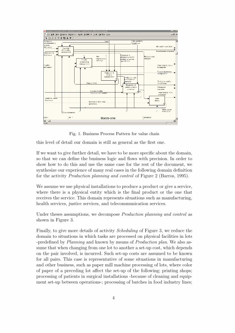
Fig. 1. Business Process Pattern for value chain
this level of detail our domain is still as general as the first one.
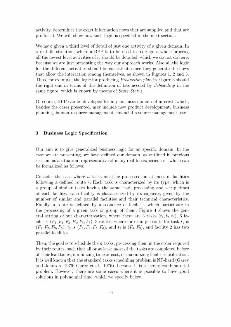
If we want to give further detail, we have to be more specific about the domain,so that we can define the business logic and flows with precision. In order toshow how to do this and use the same case for the rest of the document, wesynthesize our experience of many real cases in the following domain definitionfor the activity Production planning and control of Figure 2 (Barros, 1995).
We assume we use physical installations to produce a product or give a service,where there is a physical entity which is the final product or the one thatreceives the service. This domain represents situations such as manufacturing,health services, justice services, and telecommunication services.
Under theses assumptions, we decompose Production planning and control asshown in Figure 3.
Finally, to give more details of activity Scheduling of Figure 3, we reduce thedomain to situations in which tasks are processed on physical facilities in lots-predefined by Planning and known by means of Production plan. We also as-sume that when changing from one lot to another a set-up cost, which dependson the pair involved, is incurred. Such set-up costs are assumed to be knownfor all pairs. This case is representative of some situations in manufacturingand other business, such as paper mill machine processing of lots, where colorof paper of a preceding lot affect the set-up of the following; printing shops;processing of patients in surgical installations -because of cleaning and equip-ment set-up between operations-; processing of batches in food industry lines;
4
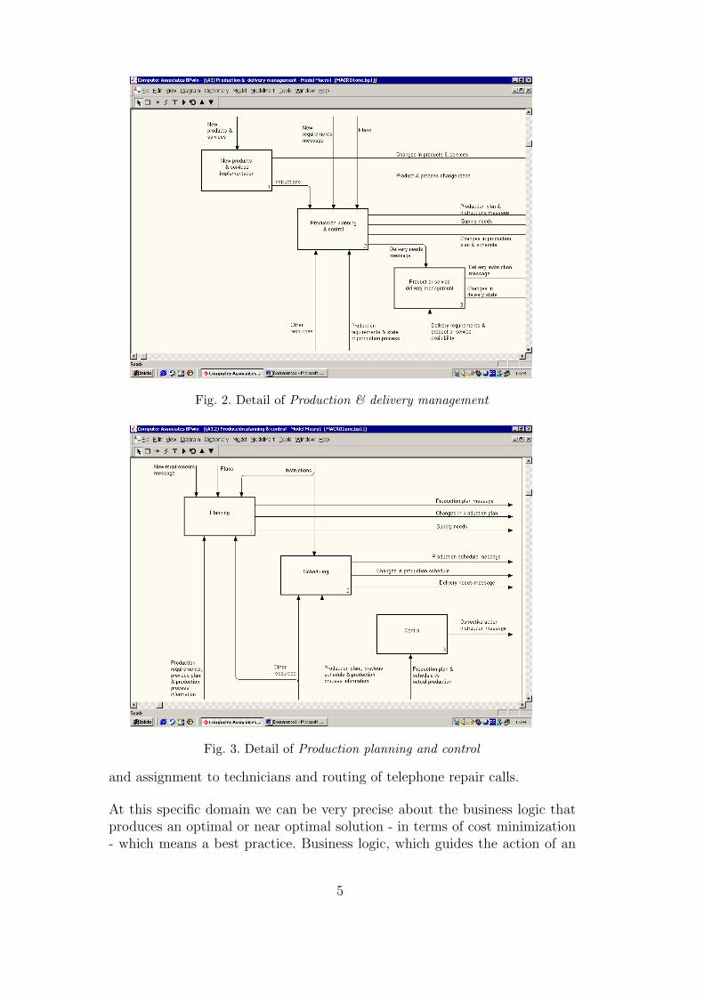
Fig. 2. Detail of Production & delivery management
Fig. 3. Detail of Production planning and control
and assignment to technicians and routing of telephone repair calls.
At this specific domain we can be very precise about the business logic thatproduces an optimal or near optimal solution - in terms of cost minimization- which means a best practice. Business logic, which guides the action of an
5
activity, determines the exact information flows that are supplied and that areproduced. We will show how such logic is specified in the next section.
We have given a third level of detail of just one activity of a given domain. Ina real-life situation, where a BPP is to be used to redesign a whole process,all the lowest level activities of it should be detailed, which we do not do here,because we are just presenting the way our approach works. Also all the logicfor the different activities should be consistent, since they generate the flowsthat allow the interaction among themselves, as shown in Figures 1, 2 and 3.Thus, for example, the logic for producing Production plan in Figure 3 shouldthe right one in terms of the definition of lots needed by Scheduling in thesame figure, which is known by means of State Status.
Of course, BPP can be developed for any business domain of interest, which,besides the cases presented, may include new product development, businessplanning, human resource management, financial resource management, etc.
3 Business Logic Specification
Our aim is to give generalized business logic for an specific domain. In thecase we are presenting, we have defined our domain, as outlined in previoussection, as a situation -representative of many real-life experiences - which canbe formalized as follows:
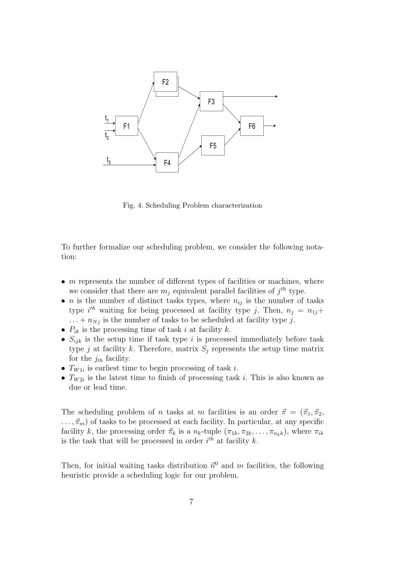
Consider the case where n tasks must be processed on at most m facilitiesfollowing a defined route r. Each task is characterized by its type, which isa group of similar tasks having the same lead, processing and setup timesat each facility. Each facility is characterized by its capacity, given by thenumber of similar and parallel facilities and their technical characteristics.Finally, a route is defined by a sequence of facilities which participate inthe processing of a given task or group of them. Figure 4 shows the gen-eral setting of our characterization, where there are 3 tasks (t1, t2, t3), 6 fa-cilities (F1, F2, F3, F4, F5, F6), 3 routes, where for example route for task t1 is(F1, F2, F3, F6), t2 is (F1, F4, F5, F6), and t3 is (F4, F3), and facility 2 has twoparallel facilities.
Then, the goal is to schedule the n tasks, processing them in the order requiredby their routes, such that all or at least most of the tasks are completed beforeof their lead times, minimizing time or cost, or maximizing facilities utilization.It is well known that the standard tasks scheduling problem is NP-hard (Gareyand Johnson, 1979; Garey et al., 1976), because it is a strong combinatorialproblem. However, there are some cases where it is possible to have goodsolutions in polynomial time, which we specify below.
6
F1
F4
F3
F5
F2
F6t1
t2
t3
Fig. 4. Scheduling Problem characterization
To further formalize our scheduling problem, we consider the following nota-tion:
• m represents the number of different types of facilities or machines, wherewe consider that there are mj equivalent parallel facilities of jth type.
• n is the number of distinct tasks types, where nij is the number of taskstype ith waiting for being processed at facility type j. Then, nj = n1j+. . . + nNj is the number of tasks to be scheduled at facility type j.
• Pik is the processing time of task i at facility k.• Sijk is the setup time if task type i is processed immediately before task
type j at facility k. Therefore, matrix Sj represents the setup time matrixfor the jth facility.
• TW1i is earliest time to begin processing of task i.• TW2i is the latest time to finish of processing task i. This is also known as
due or lead time.
The scheduling problem of n tasks at m facilities is an order ~π = (~π1, ~π2,. . . , ~πm) of tasks to be processed at each facility. In particular, at any specificfacility k, the processing order ~πk is a nk-tuple (π1k, π2k, . . . , πnkk), where πik
is the task that will be processed in order ith at facility k.
Then, for initial waiting tasks distribution ~n0 and m facilities, the followingheuristic provide a scheduling logic for our problem.
7
Heuristic Schedule(~n0, m)πj = 0, j = 1, . . . ,m~n = ~n0
SelectSet(m,~n, Φ)GetTask(Φ, ~π)if (m > 1) then
ImproveSchedule(~π)
where
• Routine SelectSet() selects a subset of tasks for every facility, where theresult is given in the m-tuple (Φ1, Φ2, . . . , Φm) of subsets of Φ.
• Routine GetTask() selects a sequence πj for the set of tasks Φj of eachfacility j, 1 ≤ j ≤ m; its implementation will depend on the specific case.
• Routine ImproveSchedule() improves the current schedule π for all facili-ties.
This heuristic synthesizes many proposals of algorithms and heuristics forsolution of problems in the domain (Beck et al., June 9-13, 2003; Johnson,1954; Thangiah et al., 1996).
In what follows we provide solutions (business logic) for both SelectSet() andGetTask() routines. Logic for ImproveSchedule() is provides when relevant.These solutions will depend on the characteristics of facilities, set-up times andlead times; some of them are proved optimum and the others are heuristics.We will concentrate on simpler cases in order to avoid very complex logic.However, these cases are useful for solving relevant real life cases, as we willshow in Section 5.
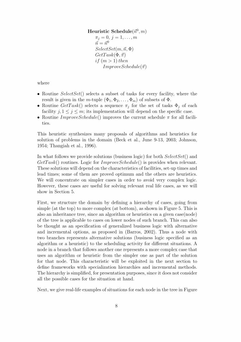
First, we structure the domain by defining a hierarchy of cases, going fromsimple (at the top) to more complex (at bottom), as shown in Figure 5. This isalso an inheritance tree, since an algorithm or heuristics on a given case(node)of the tree is applicable to cases on lower nodes of such branch. This can alsobe thought as an specification of generalized business logic with alternativeand incremental options, as proposed in (Barros, 2002). Thus a node withtwo branches represents alternative solutions (business logic specified as analgorithm or a heuristic) to the scheduling activity for different situations. Anode in a branch that follows another one represents a more complex case thatuses an algorithm or heuristic from the simpler one as part of the solutionfor that node. This characteristic will be exploited in the next section todefine frameworks with specialization hierarchies and incremental methods.The hierarchy is simplified, for presentation purposes, since it does not considerall the possible cases for the situation at hand.
Next, we give real-life examples of situations for each node in the tree in Figure
8
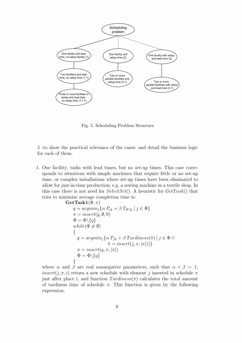
Schedulingproblem
One facility and lead time, no setup facility (1)
Two facilities and lead time, no setup time (1.1)
Three or more facilities in series and lead time, no setup time (1.1.1)
One facility andsetup time (2)
Two or more parallel facilities and
setup time (2.1)
One facility with setup and lead time (3)
Two or more parallel facilities with setup
and lead time (3.1)
Fig. 5. Scheduling Problem Structure
5 -to show the practical relevance of the cases- and detail the business logicfor each of them.
1. One facility; tasks with lead times, but no set-up times. This case corre-sponds to situations with simple machines that require little or no set-uptime, or complex installations where set-up times have been eliminated toallow for just-in-time production; e.g. a sewing machine in a textile shop. Inthis case there is not need for SelectSet(). A heuristic for GetTask() thattries to minimize average completion time is:
GetTask1(Φ, π)q = argminjα Pjk + β TW2j | j ∈ Φπ = insert(q, ∅, 0)Φ = Φ\qwhile(Φ 6= ∅)
q = argminjα Pjk + β Tardiness(π) | j ∈ Φ ∧π = insert(j, π, |π|))
π = insert(q, π, |π|)Φ = Φ\q
where α and β are real nonnegative parameters, such that α + β = 1,insert(j, π, i) return a new schedule with element j inserted in schedule πjust after place i, and function Tardiness(π) calculates the total amountof tardiness time of schedule π. This function is given by the followingexpression:
9
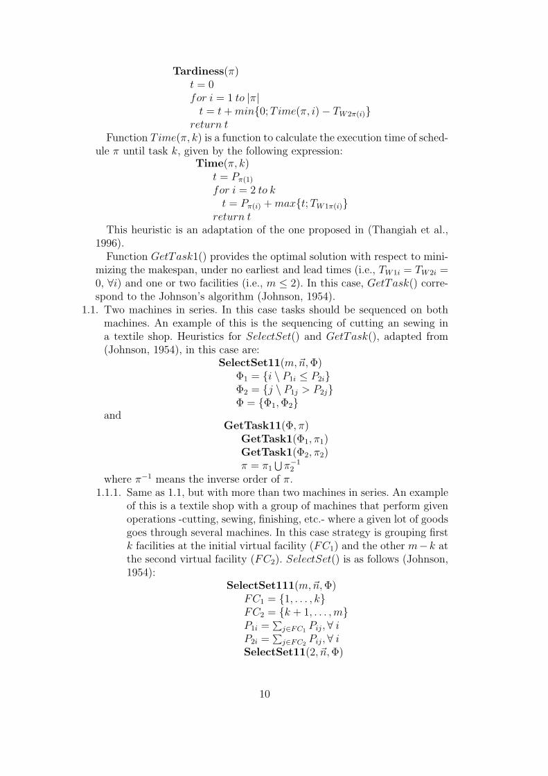
Tardiness(π)t = 0for i = 1 to |π|
t = t + min0; Time(π, i)− TW2π(i)return t
Function Time(π, k) is a function to calculate the execution time of sched-ule π until task k, given by the following expression:
Time(π, k)t = Pπ(1)
for i = 2 to kt = Pπ(i) + maxt; TW1π(i)
return tThis heuristic is an adaptation of the one proposed in (Thangiah et al.,
1996).Function GetTask1() provides the optimal solution with respect to mini-
mizing the makespan, under no earliest and lead times (i.e., TW1i = TW2i =0, ∀i) and one or two facilities (i.e., m ≤ 2). In this case, GetTask() corre-spond to the Johnson’s algorithm (Johnson, 1954).
1.1. Two machines in series. In this case tasks should be sequenced on bothmachines. An example of this is the sequencing of cutting an sewing ina textile shop. Heuristics for SelectSet() and GetTask(), adapted from(Johnson, 1954), in this case are:
SelectSet11(m,~n, Φ)Φ1 = i \ P1i ≤ P2iΦ2 = j \ P1j > P2jΦ = Φ1, Φ2
andGetTask11(Φ, π)
GetTask1(Φ1, π1)GetTask1(Φ2, π2)π = π1
⋃π−1
2
where π−1 means the inverse order of π.1.1.1. Same as 1.1, but with more than two machines in series. An example
of this is a textile shop with a group of machines that perform givenoperations -cutting, sewing, finishing, etc.- where a given lot of goodsgoes through several machines. In this case strategy is grouping firstk facilities at the initial virtual facility (FC1) and the other m−k atthe second virtual facility (FC2). SelectSet() is as follows (Johnson,1954):
SelectSet111(m,~n, Φ)FC1 = 1, . . . , kFC2 = k + 1, . . . ,mP1i =
∑j∈FC1
Pij,∀ iP2i =
∑j∈FC2
Pij,∀ iSelectSet11(2, ~n, Φ)
10
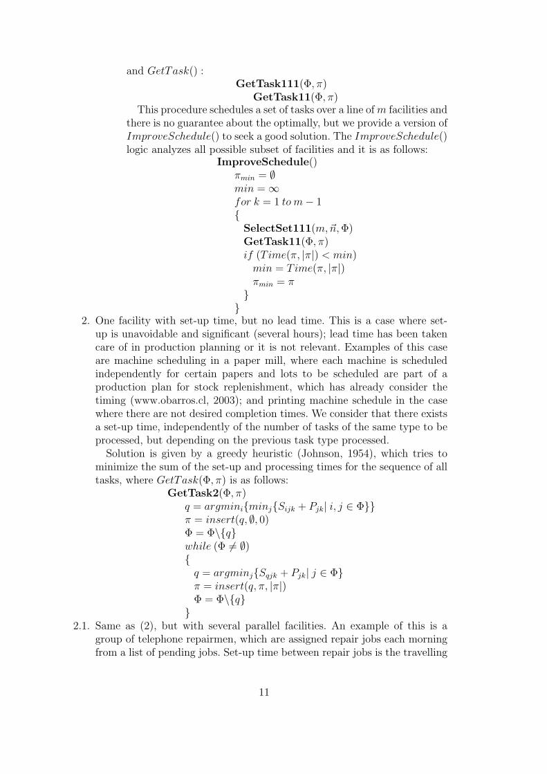
and GetTask() :GetTask111(Φ, π)
GetTask11(Φ, π)This procedure schedules a set of tasks over a line of m facilities and
there is no guarantee about the optimally, but we provide a version ofImproveSchedule() to seek a good solution. The ImproveSchedule()logic analyzes all possible subset of facilities and it is as follows:
ImproveSchedule()πmin = ∅min = ∞for k = 1 to m− 1
SelectSet111(m,~n, Φ)GetTask11(Φ, π)if (Time(π, |π|) < min)
min = Time(π, |π|)πmin = π
2. One facility with set-up time, but no lead time. This is a case where set-up is unavoidable and significant (several hours); lead time has been takencare of in production planning or it is not relevant. Examples of this caseare machine scheduling in a paper mill, where each machine is scheduledindependently for certain papers and lots to be scheduled are part of aproduction plan for stock replenishment, which has already consider thetiming (www.obarros.cl, 2003); and printing machine schedule in the casewhere there are not desired completion times. We consider that there existsa set-up time, independently of the number of tasks of the same type to beprocessed, but depending on the previous task type processed.
Solution is given by a greedy heuristic (Johnson, 1954), which tries tominimize the sum of the set-up and processing times for the sequence of alltasks, where GetTask(Φ, π) is as follows:
GetTask2(Φ, π)q = argminiminjSijk + Pjk| i, j ∈ Φπ = insert(q, ∅, 0)Φ = Φ\qwhile (Φ 6= ∅)
q = argminjSqjk + Pjk| j ∈ Φπ = insert(q, π, |π|)Φ = Φ\q
2.1. Same as (2), but with several parallel facilities. An example of this is a
group of telephone repairmen, which are assigned repair jobs each morningfrom a list of pending jobs. Set-up time between repair jobs is the travelling
11
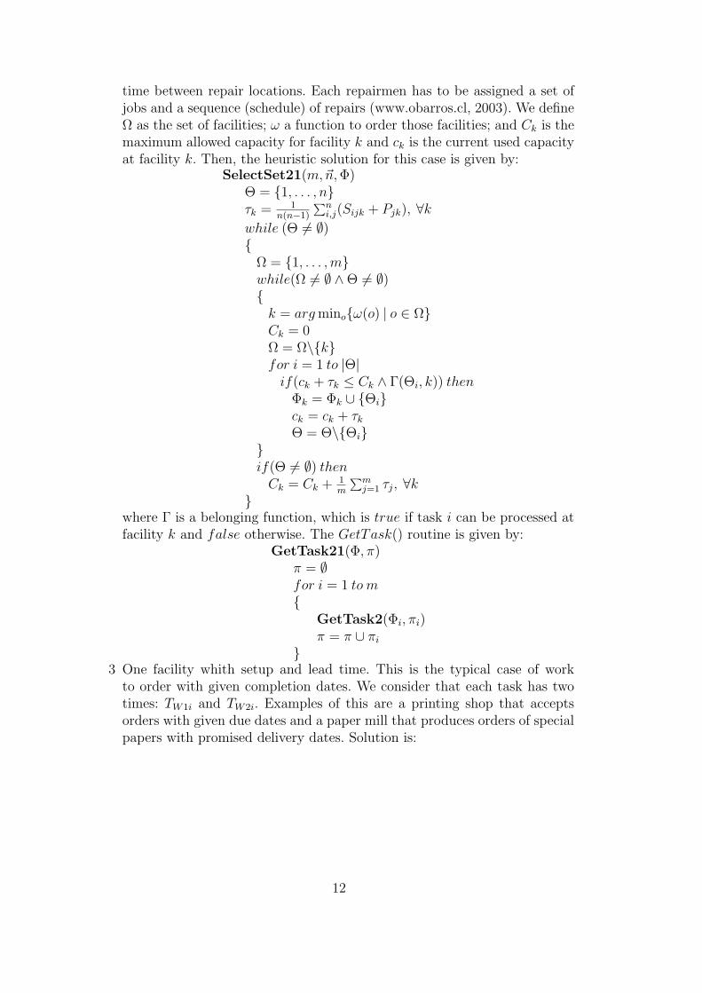
time between repair locations. Each repairmen has to be assigned a set ofjobs and a sequence (schedule) of repairs (www.obarros.cl, 2003). We defineΩ as the set of facilities; ω a function to order those facilities; and Ck is themaximum allowed capacity for facility k and ck is the current used capacityat facility k. Then, the heuristic solution for this case is given by:
SelectSet21(m,~n, Φ)Θ = 1, . . . , nτk = 1
n(n−1)
∑ni,j(Sijk + Pjk), ∀k
while (Θ 6= ∅)
Ω = 1, . . . ,mwhile(Ω 6= ∅ ∧Θ 6= ∅)
k = arg minoω(o) | o ∈ ΩCk = 0Ω = Ω\kfor i = 1 to |Θ|
if(ck + τk ≤ Ck ∧ Γ(Θi, k)) thenΦk = Φk ∪ Θick = ck + τk
Θ = Θ\Θiif(Θ 6= ∅) then
Ck = Ck + 1m
∑mj=1 τj, ∀k
where Γ is a belonging function, which is true if task i can be processed atfacility k and false otherwise. The GetTask() routine is given by:
GetTask21(Φ, π)π = ∅for i = 1 to m
GetTask2(Φi, πi)π = π ∪ πi
3 One facility whith setup and lead time. This is the typical case of work
to order with given completion dates. We consider that each task has twotimes: TW1i and TW2i. Examples of this are a printing shop that acceptsorders with given due dates and a paper mill that produces orders of specialpapers with promised delivery dates. Solution is:
12
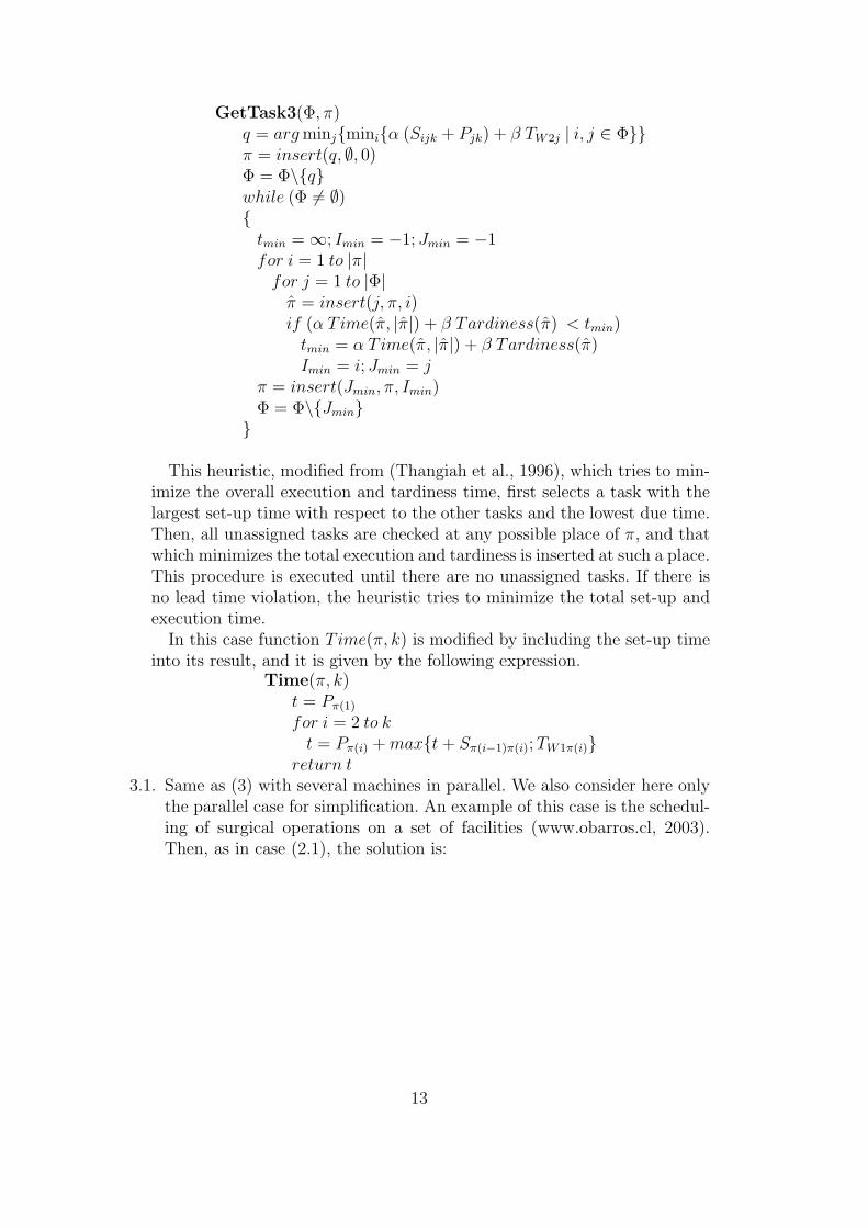
GetTask3(Φ, π)q = arg minjminiα (Sijk + Pjk) + β TW2j | i, j ∈ Φπ = insert(q, ∅, 0)Φ = Φ\qwhile (Φ 6= ∅)
tmin = ∞; Imin = −1; Jmin = −1for i = 1 to |π|
for j = 1 to |Φ|π = insert(j, π, i)if (α Time(π, |π|) + β Tardiness(π) < tmin)
tmin = α Time(π, |π|) + β Tardiness(π)Imin = i; Jmin = j
π = insert(Jmin, π, Imin)Φ = Φ\Jmin
This heuristic, modified from (Thangiah et al., 1996), which tries to min-imize the overall execution and tardiness time, first selects a task with thelargest set-up time with respect to the other tasks and the lowest due time.Then, all unassigned tasks are checked at any possible place of π, and thatwhich minimizes the total execution and tardiness is inserted at such a place.This procedure is executed until there are no unassigned tasks. If there isno lead time violation, the heuristic tries to minimize the total set-up andexecution time.
In this case function Time(π, k) is modified by including the set-up timeinto its result, and it is given by the following expression.
Time(π, k)t = Pπ(1)
for i = 2 to kt = Pπ(i) + maxt + Sπ(i−1)π(i); TW1π(i)
return t3.1. Same as (3) with several machines in parallel. We also consider here only
the parallel case for simplification. An example of this case is the schedul-ing of surgical operations on a set of facilities (www.obarros.cl, 2003).Then, as in case (2.1), the solution is:
13
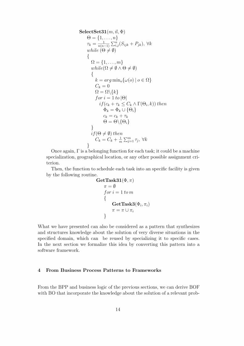
SelectSet31(m,~n, Φ)Θ = 1, . . . , nτk = 1
n(n−1)
∑ni,j(Sijk + Pjk), ∀k
while (Θ 6= ∅)
Ω = 1, . . . ,mwhile(Ω 6= ∅ ∧Θ 6= ∅)
k = arg minoω(o) | o ∈ ΩCk = 0Ω = Ω\kfor i = 1 to |Θ|
if(ck + τk ≤ Ck ∧ Γ(Θi, k)) thenΦk = Φk ∪ Θick = ck + τk
Θ = Θ\Θiif(Θ 6= ∅) then
Ck = Ck + 1m
∑mj=1 τj, ∀k
Once again, Γ is a belonging function for each task; it could be a machine
specialization, geographical location, or any other possible assignment cri-terion.
Then, the function to schedule each task into an specific facility is givenby the following routine.
GetTask31(Φ, π)π = ∅for i = 1 to m
GetTask3(Φi, πi)π = π ∪ πi
What we have presented can also be considered as a pattern that synthesizesand structures knowledge about the solution of very diverse situations in thespecified domain, which can be reused by specializing it to specific cases.In the next section we formalize this idea by converting this pattern into asoftware framework.
4 From Business Process Patterns to Frameworks
From the BPP and business logic of the previous sections, we can derive BOFwith BO that incorporate the knowledge about the solution of a relevant prob-
14
lem in the given domain. This BOF has as a purpose to provide a generalizedsolution to the problem that can be reused to develop an object-based softwareapplication for any particular real-life situation in the domain.
The mapping from BPP and business logic to a BOF, as proposed in (Barros,2002), is as follows:
i) The structure of the business logic of the domain gives a first cut definitionof the BO classes that encapsulate the algorithms or heuristics that solvethe problem for different cases in the domain. This structure contains,in general, alternative and incremental solutions to different cases in thedomain, as shown in Figure 5, for the scheduling problem.
ii) Structure of the BO can then be modelled using UML class diagrams,and operations or methods for classes defined according to business logic.
iii) Data needed to execute operations can then be derived from the param-eters included in the business logic.
iv) Data can then be structured into data classes that interact with BO in(ii). A complete class diagram with BO and data classes can then bemodelled using UML.
We follow steps above for the scheduling problem.
The structure of the business logic in Figure 5 leads us directly into theBO structure of Figure 6, where we also show the operations for each class.Such structure, which is an specialization one, shows that there are meth-ods - HueristicSchedule, SelectSet, GetTask, and ImproveSchedule - which areused by all specialization classes. Then the three branches starting a the classScheduler, define three alternative cases, one with lead time, another withsetup time, and one with both. Each branch has a method which is an spe-cialization of GetTask - GetTask1(), GetTask2() and GetTask3 - which isinherited by cases immediately below in such branch. Same is true for otherbranches below this one. All these methods have been specified in the businesslogic of Section 3.
Derivation of data needed is direct from the algorithms and heuristics of thebusiness logic. Thus task data -number, type, lead time- and set-up data isnecessary for the logic. Using well known principles of object oriented design(Pree, 1994) we come out with the class model of Figure 7, where we haveintegrated it with the BO model. Also we have made same design options,assuming specific implementation technology, separating data and logic in theidea of a web application (Conallen, 1999) and adopting Java as a program-ming tool. This design has actually been coded using Java and each node inthe specialization branches has been made to work with the inherited methods.
Clearly, the framework is simplified in the sense that includes just what isnecessary to run the logic. In real-life situations, other attributes, needed to
15
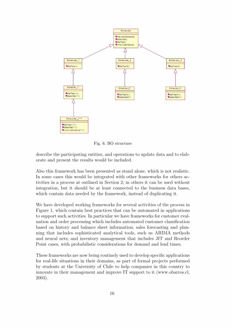
Fig. 6. BO structure
describe the participating entities, and operations to update data and to elab-orate and present the results would be included.
Also this framework has been presented as stand alone, which is not realistic.In some cases this would be integrated with other frameworks for others ac-tivities in a process at outlined in Section 2; in others it can be used withoutintegration, but it should be at least connected to the business data bases,which contain data needed by the framework, instead of duplicating it.
We have developed working frameworks for several activities of the process inFigure 1, which contain best practices that can be automated in applicationsto support such activities. In particular we have frameworks for customer eval-uation and order processing which includes automated customer classificationbased on history and balance sheet information; sales forecasting and plan-ning that includes sophisticated analytical tools, such us ARIMA methodsand neural nets; and inventory management that includes JIT and ReorderPoint cases, with probabilistic considerations for demand and lead times.
These frameworks are now being routinely used to develop specific applicationsfor real-life situations in their domains, as part of formal projects performedby students at the University of Chile to help companies in this country toinnovate in their management and improve IT support to it (www.obarros.cl,2003).
16
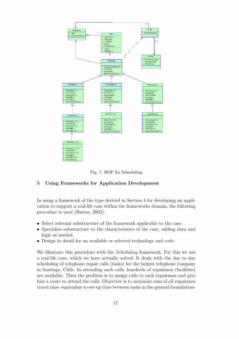
Fig. 7. BOF for Scheduling
5 Using Frameworks for Application Development
In using a framework of the type derived in Section 4 for developing an appli-cation to support a real-life case within the frameworks domain, the followingprocedure is used (Barros, 2002):
• Select relevant substructure of the framework applicable to the case.• Specialize substructure to the characteristics of the case, adding data and
logic as needed.• Design in detail for an available or selected technology and code.
We illustrate this procedure with the Scheduling framework. For this we usea real-life case, which we have actually solved. It deals with the day to dayscheduling of telephone repair calls (tasks) for the largest telephone companyin Santiago, Chile. In attending such calls, hundreds of repairmen (facilities)are available. Then the problem is to assign calls to each repairman and givehim a route to attend the calls. Objective is to minimize sum of all repairmentravel time -equivalent to set-up time between tasks in the general formulation-
17
subject to the maximum work load that can be assigned to each of them. Ad-ditionally, we would like that each repairmen has an assigned zone, where heor she will get to be known by customers and develop a good relationship withthem; then each repairmen should hopefully be assigned calls in such zone, buttrying to keep the work load balanced among repairmen by eventually assign-ing him -if he has time available- calls from other zones where the repairmanis overloaded.
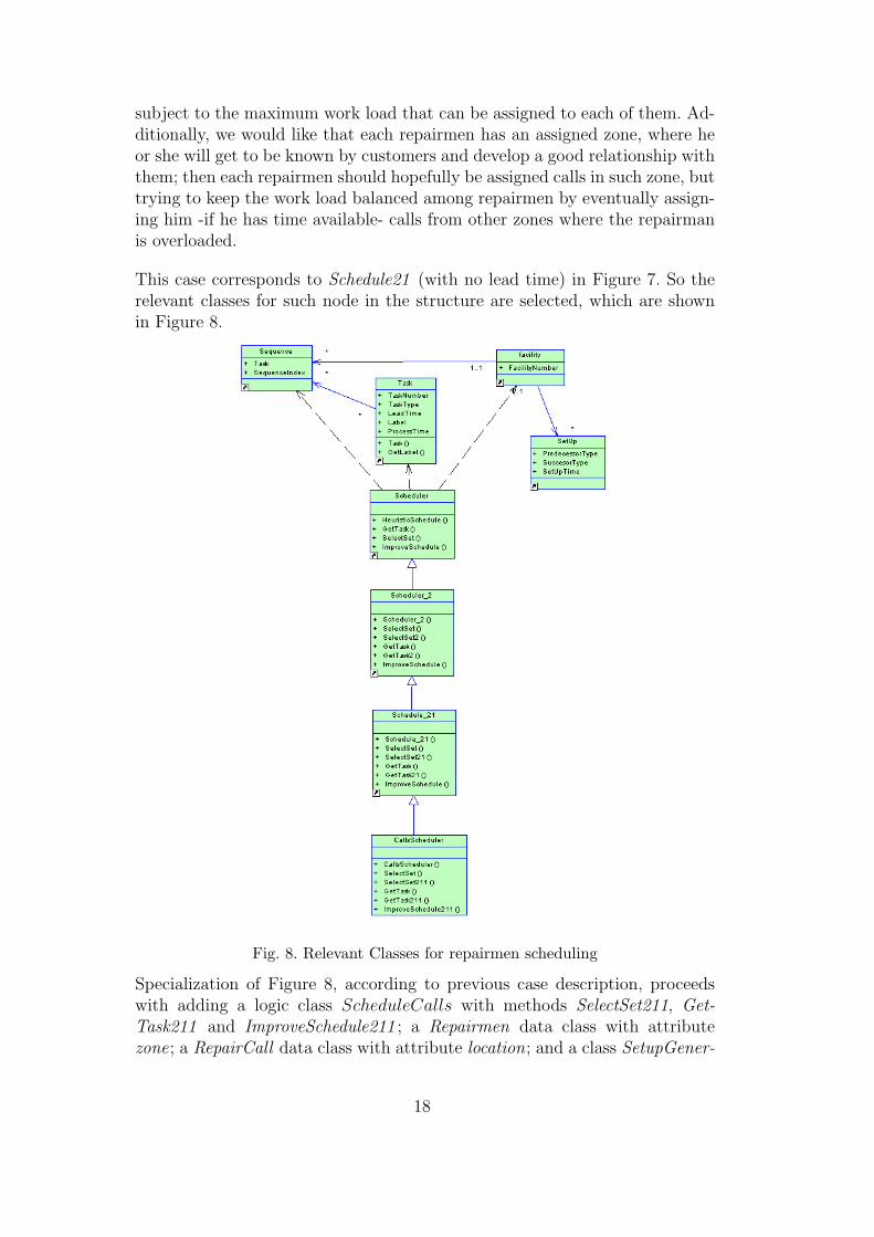
This case corresponds to Schedule21 (with no lead time) in Figure 7. So therelevant classes for such node in the structure are selected, which are shownin Figure 8.
Fig. 8. Relevant Classes for repairmen scheduling
Specialization of Figure 8, according to previous case description, proceedswith adding a logic class ScheduleCalls with methods SelectSet211, Get-Task211 and ImproveSchedule211 ; a Repairmen data class with attributezone; a RepairCall data class with attribute location; and a class SetupGener-
18
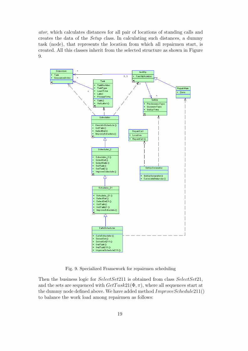
ator, which calculates distances for all pair of locations of standing calls andcreates the data of the Setup class. In calculating such distances, a dummytask (node), that represents the location from which all repairmen start, iscreated. All this classes inherit from the selected structure as shown in Figure9.
Fig. 9. Specialized Framework for repairmen scheduling
Then the business logic for SelectSet211 is obtained from class SelectSet21,and the sets are sequenced with GetTask21(Φ, π), where all sequences start atthe dummy node defined above. We have added method ImproveSchedule211()to balance the work load among repairmen as follows:
19
Method ImproveSchedule211(~n, m,~π)hk = Time(π, |π|)− C, ∀kσπ = 1
n2
∑nk=1(hk − hk)
2
while(σπ > ξ)
πk = πk, ∀kν = arg minkhkfor i = 1 to |πν |
κ = πνi
πν = πν\πνij = 1while(j ≤ m ∧ j 6= ν)
fork = 1 to |πj|π′
j = inser(πνi, πj, k)
Slack(π, π′j)
if(hj ≤ 0 ∧ σπ ≤ σπ)πj = insert(πνi, πj, k)σπ = σπ
πk = πk, ∀k
We have also coded the solution for this repairmen scheduling problem bytaking the Java code developed for the Scheduling framework and specializingit according to the additions in this section. In a sequel paper we will reportthe results obtained in the actual use of the solutions to solve the problem.
6 Conclusions and Future Work
We have shown in detail the workings of our approach for developing BOFbased on BPP. This included the application of the example framework to areal life case of moderate complexity. The relevance of such framework andthe easiness of its use confirm our claim of its flexibility and reusability insituations were non trivial business logic makes other approaches difficult toimplement. So it is apparently feasible to have the best of two worlds in thesupport of complex business decisions: the advantages of pre built software -with savings in developing costs- and the option to easily customize a solutionto the specific characteristics of a given case.
Our research is continuing in several directions. First, we are applying theexample framework of this paper to the actual solution of real life assign-ment and routing problems in companies of the telecommunications industryin Chile. Numerical results of such application will be presented in a sequel
20
paper. Second, such framework is being extended to include cases not includedin it; in particular, for situations with several facilities in any configuration.Thirdly, frameworks for other activities in the value chain defined in this paper-customer evaluation, sales predictions and production/supply management-are being perfected. We are also working in the integration of these frame-works; in particular we have developed an integrated framework -which coversthe whole value chain- with practices adapted to small and medium sizedcompanies. Finally, we are perfecting the way to deliver these frameworks forpractical use, by using technologies such as EJB and web services. A first testof these technologies was done with the framework for small and medium sizedcompanies which was developed using EJB.
Akcnowledgements
Authors appreciate the help of Sebastian Rıos in the coding of the Schedulingframework and its applications to the repairmen scheduling case.
References
Barros, O., 1995. Reingenierıa de Procesos de Negocios: Un EnfoqueMetodologico. Dolmen.
Barros, O., 2000. Rediseno de Procesos de Negocios mediante el uso de Pa-trones. Dolmen.
Barros, O., 2002. Componentes de logica del negocio desarrollados a partir depatrones de procesos. Ingenierıa de Sistemas XVI (1), 3–20.
Beck, J., Prosser, P., Selensky, E., June 9-13, 2003. Vehicle routing and jobshop scheduling: What’s the difference? In: ICAPS 2003 (13th InternationalConference on Automated Planning and Scheduling). Trento, Italy.
Bohrer, K., Johnson, V., Nilsson, A., Rubin, R., 1998. Business process com-ponents for distributed object applications. Communications of the ACM41 (6), 43–49.
Cline, M., Girou, M., 2000. Enduring business themes. Communications of theACM 43 (5), 101–106.
Conallen, J., 1999. Modeling web application architectures with UML. Com-munications of the ACM 42 (10), 63–77.
D’Sousa, D., Nills, A., 1999. Objects Components and Frameworks with UML.Addison-Wesley.
Fan, M., Stallaert, J., Whinston, A., 2000. The adoption and design method-ologies of component-based enterprise systems. European Journal of Infor-mation Systems (9), 25–35.
21
Fowler, M., 1996. Analysis Patterns: Reusable Objects Models. Addison-Wesley.
Garey, M., Johnson, D., 1979. Computers and Intractability: A Guide to theTheory of NP-Completeness. Freeman.
Garey, M., Johnson, D., Sethi, R., 1976. The complexity of flowshop andjobshop scheduling. Math. Operation Research (1), 117–129.
Hieleber, R., Kelly, T., Ketterman, C., 1998. Best Practices. Simon & Schuster.Johnson, S., 1954. Optimal two- and three-stage production schedules with
setup times included. Naval Research Logistics Quarterly (1), 61–68.Porter, M., 1986. Competitive Strategy. Free Press.Pree, W., 1994. Design Patterns for Object-Oriented Software Development.
ACM Press Books - Addison-Wesley.Thangiah, S., Potvin, J., Sun, T., 1996. Heuristic approaches to vehicle routing
with backhauls and time windows. Internation Journal of Computers andOperations Researc 23 (11), 1043–1057.
www.bwpccoe.org, 2003.www.ebusinessforum.com, 2003.www.obarros.cl, 2003.www.siebel.com/bestpractices, 2003.
22


![Derived Patterns in Binocular Rivalry Networksdiekman/papers/DiekmanGolubitskyWang13.pdf · Derived Patterns in Binocular Rivalry Networks ... (Blake and Logothetis [6]): ... when](https://img.pdfslide.us/doc/110x75/5ad8d8e77f8b9a991b8dd77b/derived-patterns-in-binocular-rivalry-networks-diekmanpapersdie-patterns-in-binocular.jpg)