Embed Size (px)
Citation preview
PNNL-13411
FRAMES User Defined Source Release Module Documentation JW Buck MA Pelton MA Eslinger December 2000 Prepared for the U.S. Department of Energy under Contract DE-AC06-76RL01830
DISCLAIMER
This report was prepared as an account of work sponsored by an agency of theUnited States Government. Neither the United States Government nor any agencythereof, nor Battelle Memorial Institute, nor any of their employees, makes anywarranty, express or implied, or assumes any legal liability or responsibility forthe accuracy, completeness, or usefulness of any information, apparatus,product, or process disclosed, or represents that its use would not infringeprivately owned rights. Reference herein to any specific commercial product,process, or service by trade name, trademark, manufacturer, or otherwise does notnecessarily constitute or imply its endorsement, recommendation, or favoring bythe United States Government or any agency thereof, or Battelle MemorialInstitute. The views and opinions of authors expressed herein do not necessarilystate or reflect those of the United States Government or any agency thereof.
PACIFIC NORTHWEST NATIONAL LABORATORYoperated byBATTELLE
for theUNITED STATES DEPARTMENT OF ENERGY
under Contract DE-AC06-76RLO 1830
Printed in the United States of America
Available to DOE and DOE contractors from theOffice of Scientific and Technical Information, P.O. Box 62, Oak Ridge, TN
37831;prices available from (615) 576-8401.
Available to the public from the National Technical Information Service,U.S. Department of Commerce, 5285 Port Royal Rd., Springfield, VA 22161
This document was printed on recycled paper.
PNNL-13411
FRAMES User Defined Source Release Module Documentation
J. W. BuckM. A. PeltonM. A. Eslinger
December 2000
Prepared forU.S. Department of Energyunder Contract DE-AC06-76RL01830
Pacific Northwest National LaboratoryRichland, Washington 99352
iii
Contents
1.0 Introduction . . . . . . . . . . . . . . . . . . . . . . . . . . . . . . . . . . . . . . . . . . . . . . . . . . . . . . . . . . . . . . . . 1
2.0 Purpose of FRAMES User-Defined Source Release Module . . . . . . . . . . . . . . . . . . . . . . . . . . . . . . . 1
3.0 Summary of Requirements for the FRAMES User-Defined Source Release Module . . . . . . . . . . . . . . 23.1 Input Requirements for the FRAMES Use-Defined Source Release Module . . . . . . . . . . . 23.2 Output Requirements for the FRAMES User-Defined Source Release Module . . . . . . . . . . 43.3 Scientific Requirements for the FRAMES User-Defined Source Release Module . . . . . . . . 4
4.0 Recommendations . . . . . . . . . . . . . . . . . . . . . . . . . . . . . . . . . . . . . . . . . . . . . . . . . . . . . . . . . . . . 5
5.0 Test Plan . . . . . . . . . . . . . . . . . . . . . . . . . . . . . . . . . . . . . . . . . . . . . . . . . . . . . . . . . . . . . . . . . . 65.1 Summary of Requirements . . . . . . . . . . . . . . . . . . . . . . . . . . . . . . . . . . . . . . . . . . . . . . . . 65.2 Test Case 1- Air . . . . . . . . . . . . . . . . . . . . . . . . . . . . . . . . . . . . . . . . . . . . . . . . . . . . . . . 7
5.2.1 Description and Rationale . . . . . . . . . . . . . . . . . . . . . . . . . . . . . . . . . . . . . . . . . 75.2.2 Input . . . . . . . . . . . . . . . . . . . . . . . . . . . . . . . . . . . . . . . . . . . . . . . . . . . . . . . . 75.2.3 Expected Results . . . . . . . . . . . . . . . . . . . . . . . . . . . . . . . . . . . . . . . . . . . . . . . 85.2.4 Conducting Test . . . . . . . . . . . . . . . . . . . . . . . . . . . . . . . . . . . . . . . . . . . . . . . . 85.2.5 Result . . . . . . . . . . . . . . . . . . . . . . . . . . . . . . . . . . . . . . . . . . . . . . . . . . . . . . . 9
5.3 Test Case #2 Water . . . . . . . . . . . . . . . . . . . . . . . . . . . . . . . . . . . . . . . . . . . . . . . . . . . . . 95.3.1 Description and Rationale . . . . . . . . . . . . . . . . . . . . . . . . . . . . . . . . . . . . . . . . . 95.3.2 Input . . . . . . . . . . . . . . . . . . . . . . . . . . . . . . . . . . . . . . . . . . . . . . . . . . . . . . . . 95.3.3 Expected Results . . . . . . . . . . . . . . . . . . . . . . . . . . . . . . . . . . . . . . . . . . . . . . 115.3.4 Conducting Test . . . . . . . . . . . . . . . . . . . . . . . . . . . . . . . . . . . . . . . . . . . . . . . 125.3.5 Result . . . . . . . . . . . . . . . . . . . . . . . . . . . . . . . . . . . . . . . . . . . . . . . . . . . . . . 12
5.4 Test Case #3 Overland . . . . . . . . . . . . . . . . . . . . . . . . . . . . . . . . . . . . . . . . . . . . . . . . . . 125.4.1 Description and Rationale . . . . . . . . . . . . . . . . . . . . . . . . . . . . . . . . . . . . . . . . 12
5.5 Test Case #4 Soil (Case 2B) . . . . . . . . . . . . . . . . . . . . . . . . . . . . . . . . . . . . . . . . . . . . . . 135.5.1 Description and Rationale . . . . . . . . . . . . . . . . . . . . . . . . . . . . . . . . . . . . . . . . 135.5.2 Input . . . . . . . . . . . . . . . . . . . . . . . . . . . . . . . . . . . . . . . . . . . . . . . . . . . . . . . 135.5.3 Expected Results . . . . . . . . . . . . . . . . . . . . . . . . . . . . . . . . . . . . . . . . . . . . . . 145.5.4 Conducting Test . . . . . . . . . . . . . . . . . . . . . . . . . . . . . . . . . . . . . . . . . . . . . . . 145.5.5 Results . . . . . . . . . . . . . . . . . . . . . . . . . . . . . . . . . . . . . . . . . . . . . . . . . . . . . 15
5.6 Test Case 5-All . . . . . . . . . . . . . . . . . . . . . . . . . . . . . . . . . . . . . . . . . . . . . . . . . . . . . . . 155.6.1 Description and Rationale . . . . . . . . . . . . . . . . . . . . . . . . . . . . . . . . . . . . . . . . 15
6.0 Quality Assurance Program . . . . . . . . . . . . . . . . . . . . . . . . . . . . . . . . . . . . . . . . . . . . . . . . . . . . 16
7.0 References . . . . . . . . . . . . . . . . . . . . . . . . . . . . . . . . . . . . . . . . . . . . . . . . . . . . . . . . . . . . . . . . 21
Appendix A: General Procedure for Test Case Implementation . . . . . . . . . . . . . . . . . . . . . . . . . . . . . . A.1

iv
v
Figures
1. Error Message . . . . . . . . . . . . . . . . . . . . . . . . . . . . . . . . . . . . . . . . . . . . . . . . . . . . . . . . . . . . . 122. Ensuring Quality in the Environmental Software Development Process . . . . . . . . . . . . . . . . . . . . 17
3. Quality Assurance Implementation Checklist for the FRAMES Technology Software System . . . . . . . . . . . . . . . . . . . . . . . . . . . . . . . . . . . . . . . . . . . . . . . . . . . . . . . . . . . 19
Tables
1. Relationship of PNNL Environmental Software Development Process to Quality Assurance Requirements . . . . . . . . . . . . . . . . . . . . . . . . . . . . . . . . . . . . . . . . . . . . . . . . 18
1
1.0 Introduction
The Framework for Risk Analysis in Multimedia Environmental Systems (FRAMES) User-Defined Source Release Module is generally the starting module for most analyses when the user knowsthe release rates of the contaminants. This module provides the user a way to input the user-definedcontaminant mass fluxes for each contaminant and the user-defined media flux rates. This reportcontains the requirements for this module and will be used by software engineers and testers to ensurethat the module functions properly. A test plan will be developed from this document. Test cases will bedeveloped from the test plan to ensure that the product meets the needs of the client(s) and to establish abaseline version of the module.
2.0 Purpose of FRAMES User-Defined Source Release Module
The purpose of the FRAMES User-Defined Source Release Module is to allow the user to inputuser-defined contaminant and media release rates to generate the appropriate FRAMES data files to beused by fate and transport and exposure modules. Both radionuclides and chemicals can be input into thismodule. These contaminant mass fluxes are used to describe the loss of contaminant from the sourcezone via loss routes to various environmental media (i.e., air, soil, and water), while the media releaserates define the flow rates of the medium associated with the contaminant mass fluxes. The contaminantand media release rates are time varying, and the user must define the time steps required. The user candefine four different contaminant mass flux rate types: infiltration, overland runoff, atmospheric, and/orsoil contamination in the FRAMES User-Defined Source Release Module.
2
3.0 Summary of Requirements for the FRAMES User-Defined SourceRelease Module
This section provides an overall summary of the requirements for the FRAMES User-DefinedSource Release Module. Detailed input, output, and scientific requirements are described in the sectionsthat follow.
The FRAMES User-Defined Source Release Module will:
• Allow user to input time-varying, contaminant mass flux and media release rates for water, air, soil,and overland release mechanisms.
• Allow at least 25 contaminants to be evaluated for a scenario.
• Operate under Windows 95 and have a user-friendly interface with a standard windows look andfeel.
• Produce Air Flux File (AFF), Water Flux File (WFF), and Soil Concentration File (SCF) followingthe FRAMES data file specifications.
3.1 Input Requirements for the FRAMES Use-Defined Source ReleaseModule
The user will enter the input data required for the FRAMES User-Defined Source ReleaseModule via the Module User Interface (MUI). The MUI will allow the user to define the source problemand associated data. The three main inputs to the FRAMES User-Defined Source Release Module MUIare 1) the medium type of source being modeled, 2) time-varying, contaminant mass fluxes, and 3) time-varying, media release rates. The media release rate types depend on which modules are connected tothis source module. If a vadose or aquifer module is connected, water fluxes will be required; if anoverland or surface water module is connected, sediment fluxes will be required; if an atmosphericmodule is connected, air emission rates are required; and if an exposure module is connected, soilconcentrations are required. The appropriate tabs should appear in the MUI based on the Modulesconnected.
The following general requirements are associated with the MUI:
1) The MUI will operate in Windows 95 and will have a standard Windows look and feel.
2) The MUI will have online help in an HTML format that provides users with an easy-to-understanddescription of all input parameters required by the MUI as well as an About tab to inform the user ofthe module title, version number, and brief description.
3) For all input parameters having dimensions associated with them, the MUI will provide users with achoice of units.
4) The MUI will include a reference feature in which the source of the specified value for each inputitem can be referenced if the user desires.
3
The MUI will show the range of values allowed for each input data item, when the cursor ispositioned on that item, as a message at the bottom of the screen will appear. When an out-of-rangevalue is entered in a field, the MUI will indicate this by a red background in the input field and an errormessage in addition to the allowed range message. Data input values within range are shown with agreen field background.
The MUI for the FRAMES User-Defined Source Release Module must allow the user to input allthe required data to execute the module. This includes allowing the user to enter data for:
• User-defined, time-varying, instantaneous contaminant mass fluxes and media release rates forwater media (aquifer, surface water, or vadose zone medium)
• User-defined, time-varying, instantaneous contaminant mass fluxes and media release rates foroverland medium
• User-defined, time-varying, annual average contaminant mass fluxes and media release rates forair medium
• User-defined, time-varying, instantaneous contaminant concentrations for soil in the waste zone.
There are four main data categories associated with the FRAMES User-Defined Source ReleaseModule and each of these categories, when selected, have requirements for entering data. The followingdata are obtained from the MUI and are needed by the module: 1) water flux, 2) overland flux, 3)atmospheric flux, and 4) soil concentration.
The data requirements for the Water Flux category are:
• Medium type (i.e., aquifer, vadose, or surface water)• Width of flux plane • Length of flux plane (vadose or surface water only)• Height of flux plane (aquifer only )• Distance below water table • Natural recharge rate • User-defined, time-varying, instantaneous contaminant mass fluxes for each contaminant• User-defined, time-varying, instantaneous medium release rates.
The data requirements for the Overland Flux category are:
• Medium type (vadose or surface water)• Width of flux plane• Height of flux plane• Distance below water table• Natural recharge rate• User-defined, time-varying, instantaneous contaminant mass fluxes for each contaminant• User-defined, time-varying, instantaneous medium release rates.
The data requirements for the Atmospheric Flux category are:
4
• Flux types (gas 1, particle 1, particle 2, or particle 3)• Flux type flux density (gas and particles) and particle radius (particles only)• Type of Release (point or area)• Exit area of source• Exit height of source (point only)• Height of adjacent structures (point only)• Exit velocity of source (point only)• Exit temperature of source (point only)• Ambient air temperature (point only)• User-defined, time-varying, annual average contaminant mass fluxes for each contaminant• User-defined, time-varying, annual average medium release rates (gas or particle).
The data requirements for the Soil Concentration category are:
• Type of contaminated medium (vadose)• Width of contaminated soil• Length of contaminated soil• Depth of contaminated soil• User-defined, time-varying, instantaneous contaminant soil concentration for each contaminant.
3.2 Output Requirements for the FRAMES User-Defined Source ReleaseModule
The FRAMES User-Defined Source Release Module is required to output time-varying,contaminant mass fluxes for air, water, and overland, as well as soil concentrations associated with thesource medium. These outputs must meet the specifications of the FRAMES (Whelan et al. 1997). Themass flux of contaminant to the air medium must be provided in the *.AFF file, the mass flux ofcontaminant to the water and overland media in the *.WFF file, and the soil concentrations remaining atthe source for each time step must be provided in the *.SCF file.
The FRAMES User-Defined Source Release Module outputs the following data to the AFF,WFF, and SCF:
• Time-varying, annual average contaminant particle and gaseous emission rates (AFF)• Time-varying, instantaneous contaminant infiltration and overland runoff flux rates (WFF)• Time-varying, instantaneous contaminant soil concentrations at the source (SCF)• Time-varying, instantaneous infiltration, soil erosion, and wind erosion rates (WFF and AFF)
3.3 Scientific Requirements for the FRAMES User-Defined Source ReleaseModule
The FRAMES User-Defined Source Release Module does not conduct computations that changethe values input by the user except to convert units to internal FRAMES units. This is done by the MUI. No other scientific requirements exist for this Module.

5
6
4.0 Recommendations
• Allow the user to enter known ground water or surface water concentrations (WCF format).
• Allow the user to enter know air concentrations and deposition rates (ATO format).
• Allow the user to enter known concentrations at the receptor for chemical and radionuclide (EPFformat).
• Allow the user to enter known intake rates for chemicals and radionuclides (RIF format).
• Allow the user to enter known impact values for contaminants by receptor (HIF format).
• Although the MUI will convert the dimensions of user input data values into the units needed bythe model, the MUI will always display the exact value and units in which the user originallyentered each input data item.
7
5.0 Test Plan
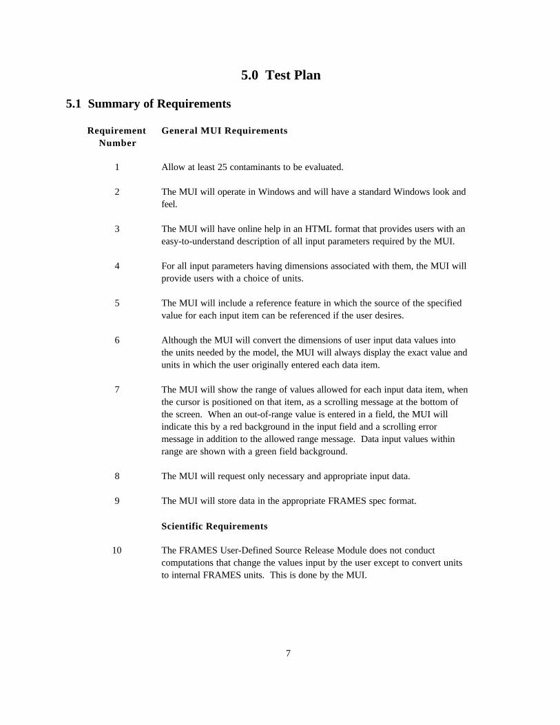
5.1 Summary of Requirements
RequirementNumber
General MUI Requirements
1 Allow at least 25 contaminants to be evaluated.
2 The MUI will operate in Windows and will have a standard Windows look andfeel.
3 The MUI will have online help in an HTML format that provides users with aneasy-to-understand description of all input parameters required by the MUI.
4 For all input parameters having dimensions associated with them, the MUI willprovide users with a choice of units.
5 The MUI will include a reference feature in which the source of the specifiedvalue for each input item can be referenced if the user desires.
6 Although the MUI will convert the dimensions of user input data values intothe units needed by the model, the MUI will always display the exact value andunits in which the user originally entered each data item.
7 The MUI will show the range of values allowed for each input data item, whenthe cursor is positioned on that item, as a scrolling message at the bottom ofthe screen. When an out-of-range value is entered in a field, the MUI willindicate this by a red background in the input field and a scrolling errormessage in addition to the allowed range message. Data input values withinrange are shown with a green field background.
8 The MUI will request only necessary and appropriate input data.
9 The MUI will store data in the appropriate FRAMES spec format.
Scientific Requirements
10 The FRAMES User-Defined Source Release Module does not conductcomputations that change the values input by the user except to convert unitsto internal FRAMES units. This is done by the MUI.
8
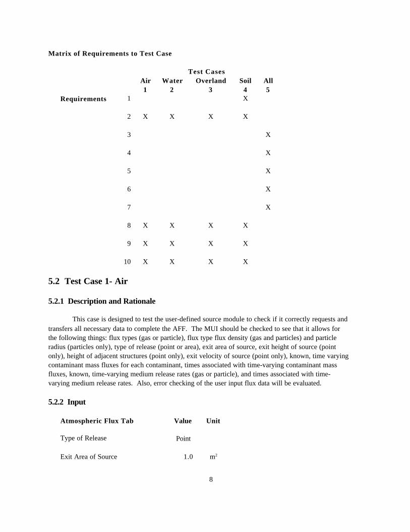
Matrix of Requirements to Test Case
Test CasesAir1
Water2
Overland3
Soil4
All5
Requirements 1 X
2 X X X X
3 X
4 X
5 X
6 X
7 X
8 X X X X
9 X X X X
10 X X X X
5.2 Test Case 1- Air
5.2.1 Description and Rationale
This case is designed to test the user-defined source module to check if it correctly requests andtransfers all necessary data to complete the AFF. The MUI should be checked to see that it allows forthe following things: flux types (gas or particle), flux type flux density (gas and particles) and particleradius (particles only), type of release (point or area), exit area of source, exit height of source (pointonly), height of adjacent structures (point only), exit velocity of source (point only), known, time varyingcontaminant mass fluxes for each contaminant, times associated with time-varying contaminant massfluxes, known, time-varying medium release rates (gas or particle), and times associated with time-varying medium release rates. Also, error checking of the user input flux data will be evaluated.
5.2.2 Input
Atmospheric Flux Tab Value Unit
Type of Release Point
Exit Area of Source 1.0 m2
9
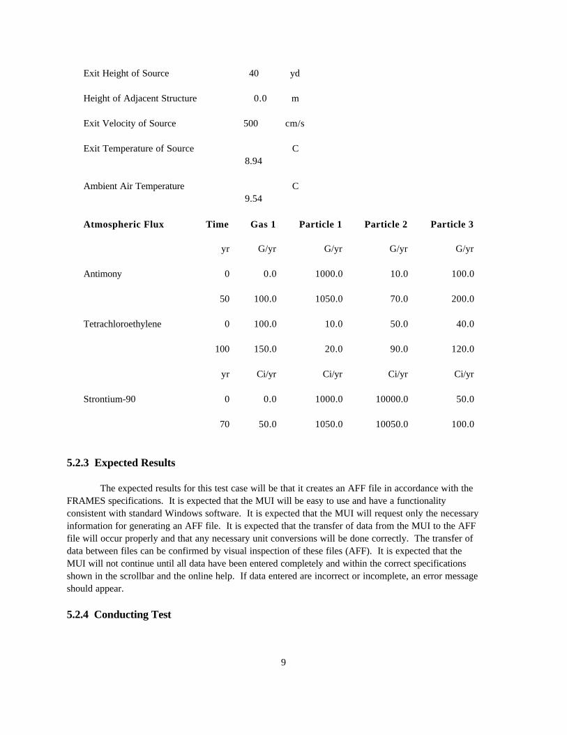
Exit Height of Source 40 yd
Height of Adjacent Structure 0.0 m
Exit Velocity of Source 500 cm/s
Exit Temperature of Source 8.94
C
Ambient Air Temperature 9.54
C
Atmospheric Flux Time Gas 1 Particle 1 Particle 2 Particle 3
yr G/yr G/yr G/yr G/yr
Antimony 0 0.0 1000.0 10.0 100.0
50 100.0 1050.0 70.0 200.0
Tetrachloroethylene 0 100.0 10.0 50.0 40.0
100 150.0 20.0 90.0 120.0
yr Ci/yr Ci/yr Ci/yr Ci/yr
Strontium-90 0 0.0 1000.0 10000.0 50.0
70 50.0 1050.0 10050.0 100.0
5.2.3 Expected Results
The expected results for this test case will be that it creates an AFF file in accordance with theFRAMES specifications. It is expected that the MUI will be easy to use and have a functionalityconsistent with standard Windows software. It is expected that the MUI will request only the necessaryinformation for generating an AFF file. It is expected that the transfer of data from the MUI to the AFFfile will occur properly and that any necessary unit conversions will be done correctly. The transfer ofdata between files can be confirmed by visual inspection of these files (AFF). It is expected that theMUI will not continue until all data have been entered completely and within the correct specificationsshown in the scrollbar and the online help. If data entered are incorrect or incomplete, an error messageshould appear.
5.2.4 Conducting Test
10
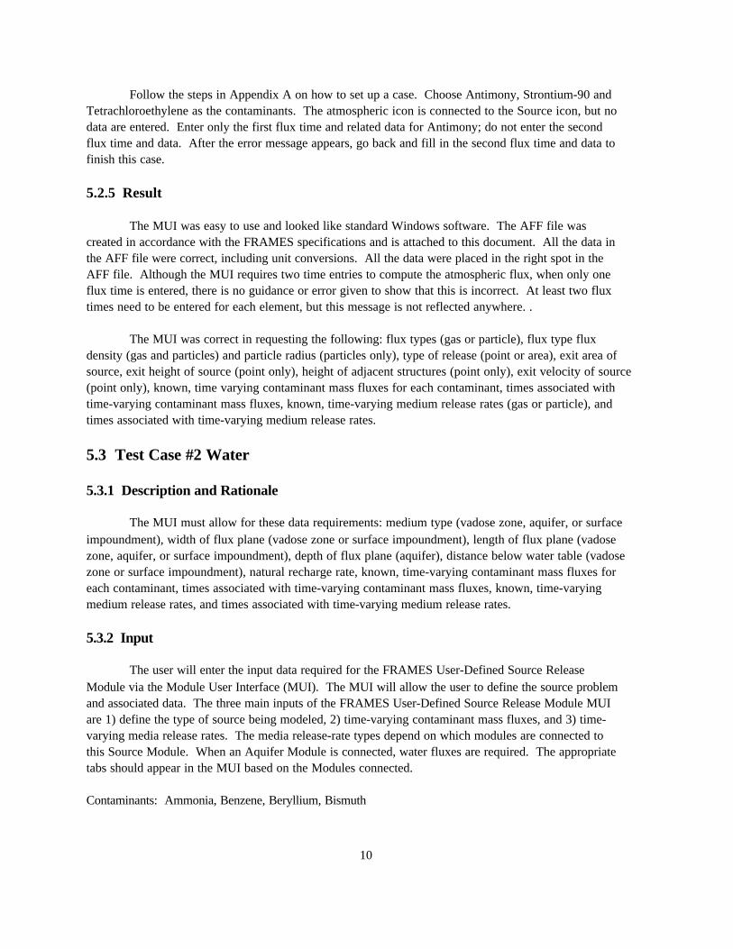
Follow the steps in Appendix A on how to set up a case. Choose Antimony, Strontium-90 andTetrachloroethylene as the contaminants. The atmospheric icon is connected to the Source icon, but nodata are entered. Enter only the first flux time and related data for Antimony; do not enter the secondflux time and data. After the error message appears, go back and fill in the second flux time and data tofinish this case.
5.2.5 Result
The MUI was easy to use and looked like standard Windows software. The AFF file wascreated in accordance with the FRAMES specifications and is attached to this document. All the data inthe AFF file were correct, including unit conversions. All the data were placed in the right spot in theAFF file. Although the MUI requires two time entries to compute the atmospheric flux, when only oneflux time is entered, there is no guidance or error given to show that this is incorrect. At least two fluxtimes need to be entered for each element, but this message is not reflected anywhere. .
The MUI was correct in requesting the following: flux types (gas or particle), flux type fluxdensity (gas and particles) and particle radius (particles only), type of release (point or area), exit area ofsource, exit height of source (point only), height of adjacent structures (point only), exit velocity of source(point only), known, time varying contaminant mass fluxes for each contaminant, times associated withtime-varying contaminant mass fluxes, known, time-varying medium release rates (gas or particle), andtimes associated with time-varying medium release rates.
5.3 Test Case #2 Water
5.3.1 Description and Rationale
The MUI must allow for these data requirements: medium type (vadose zone, aquifer, or surfaceimpoundment), width of flux plane (vadose zone or surface impoundment), length of flux plane (vadosezone, aquifer, or surface impoundment), depth of flux plane (aquifer), distance below water table (vadosezone or surface impoundment), natural recharge rate, known, time-varying contaminant mass fluxes foreach contaminant, times associated with time-varying contaminant mass fluxes, known, time-varyingmedium release rates, and times associated with time-varying medium release rates.
5.3.2 Input
The user will enter the input data required for the FRAMES User-Defined Source ReleaseModule via the Module User Interface (MUI). The MUI will allow the user to define the source problemand associated data. The three main inputs of the FRAMES User-Defined Source Release Module MUIare 1) define the type of source being modeled, 2) time-varying contaminant mass fluxes, and 3) time-varying media release rates. The media release-rate types depend on which modules are connected tothis Source Module. When an Aquifer Module is connected, water fluxes are required. The appropriatetabs should appear in the MUI based on the Modules connected.
Contaminants: Ammonia, Benzene, Beryllium, Bismuth
11
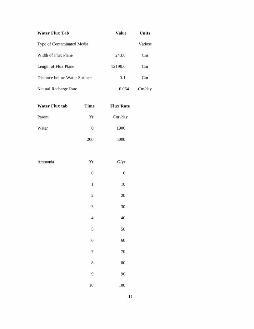
Water Flux Tab Value Units
Type of Contaminated Media Vadose
Width of Flux Plane 243.8 Cm
Length of Flux Plane 12190.0 Cm
Distance below Water Surface 0.1 Cm
Natural Recharge Rate 0.064 Cm/day
Water Flux tab Time Flux Rate
Parent Yr Cm3/day
Water 0 1900
200 5000
Ammonia Yr G/yr
0 0
1 10
2 20
3 30
4 40
5 50
6 60
7 70
8 80
9 90
10 100
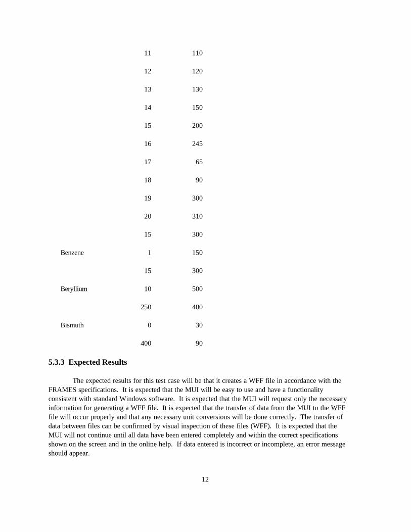
12
11 110
12 120
13 130
14 150
15 200
16 245
17 65
18 90
19 300
20 310
15 300
Benzene 1 150
15 300
Beryllium 10 500
250 400
Bismuth 0 30
400 90
5.3.3 Expected Results
The expected results for this test case will be that it creates a WFF file in accordance with theFRAMES specifications. It is expected that the MUI will be easy to use and have a functionalityconsistent with standard Windows software. It is expected that the MUI will request only the necessaryinformation for generating a WFF file. It is expected that the transfer of data from the MUI to the WFFfile will occur properly and that any necessary unit conversions will be done correctly. The transfer ofdata between files can be confirmed by visual inspection of these files (WFF). It is expected that theMUI will not continue until all data have been entered completely and within the correct specificationsshown on the screen and in the online help. If data entered is incorrect or incomplete, an error messageshould appear.
13
5.3.4 Conducting Test
Open the Multimedia Framework (fui.exe). Click on the contaminant icon. The icon will appearon the work screen. Click and hold on a Source Term icon; pull it down into the work screen. Pull downa vadose (brown and green) icon, saturated zone (mostly blue), and exposure (cow) icon. Follow theinstruction in the Appendix to finish conducting the test.
Note: To demonstrate the water-transport feature, an exposure icon must be connected to the transporticon. This exposure icon does not need to be populated with data for the water transport to bedemonstrated.
5.3.5 Result
The MUI was easy to use and looked like standard Windows software. The WFF file wascreated in accordance with the FRAMES specifications and is attached to this document. All the data inthe WFF file were correct, including unit conversions. All the data were placed in the right spot in theWFF file.
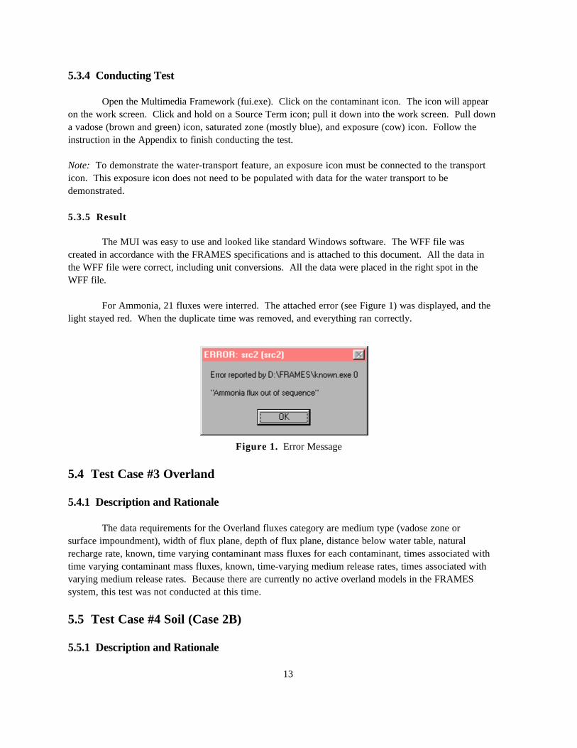
For Ammonia, 21 fluxes were interred. The attached error (see Figure 1) was displayed, and thelight stayed red. When the duplicate time was removed, and everything ran correctly.
Figure 1. Error Message
5.4 Test Case #3 Overland
5.4.1 Description and Rationale
The data requirements for the Overland fluxes category are medium type (vadose zone orsurface impoundment), width of flux plane, depth of flux plane, distance below water table, naturalrecharge rate, known, time varying contaminant mass fluxes for each contaminant, times associated withtime varying contaminant mass fluxes, known, time-varying medium release rates, times associated withvarying medium release rates. Because there are currently no active overland models in the FRAMESsystem, this test was not conducted at this time.
5.5 Test Case #4 Soil (Case 2B)
5.5.1 Description and Rationale
14
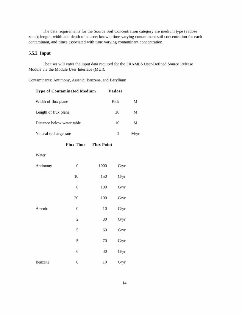
The data requirements for the Source Soil Concentration category are medium type (vadosezone); length, width and depth of source; known, time varying contaminant soil concentration for eachcontaminant, and times associated with time varying contaminant concentration.
5.5.2 Input
The user will enter the input data required for the FRAMES User-Defined Source ReleaseModule via the Module User Interface (MUI).
Contaminants: Antimony, Arsenic, Benzene, and Beryllium
Type of Contaminated Medium Vadose
Width of flux plane Kklk M
Length of flux plane 20 M
Distance below water table 10 M
Natural recharge rate 2 M/yr
Flux Time Flux Point
Water
Antimony 0 1000 G/yr
10 150 G/yr
8 100 G/yr
20 100 G/yr
Arsenic 0 10 G/yr
2 30 G/yr
5 60 G/yr
5 70 G/yr
6 30 G/yr
Benzene 0 10 G/yr
15
10 50 G/yr
11 60 G/yr
9 40 G/yr
13 80 G/yr
Beryllium 0 20 G/yr
0 30 G/yr
5 60 G/yr
8 92 G/yr
10 5 G/yr
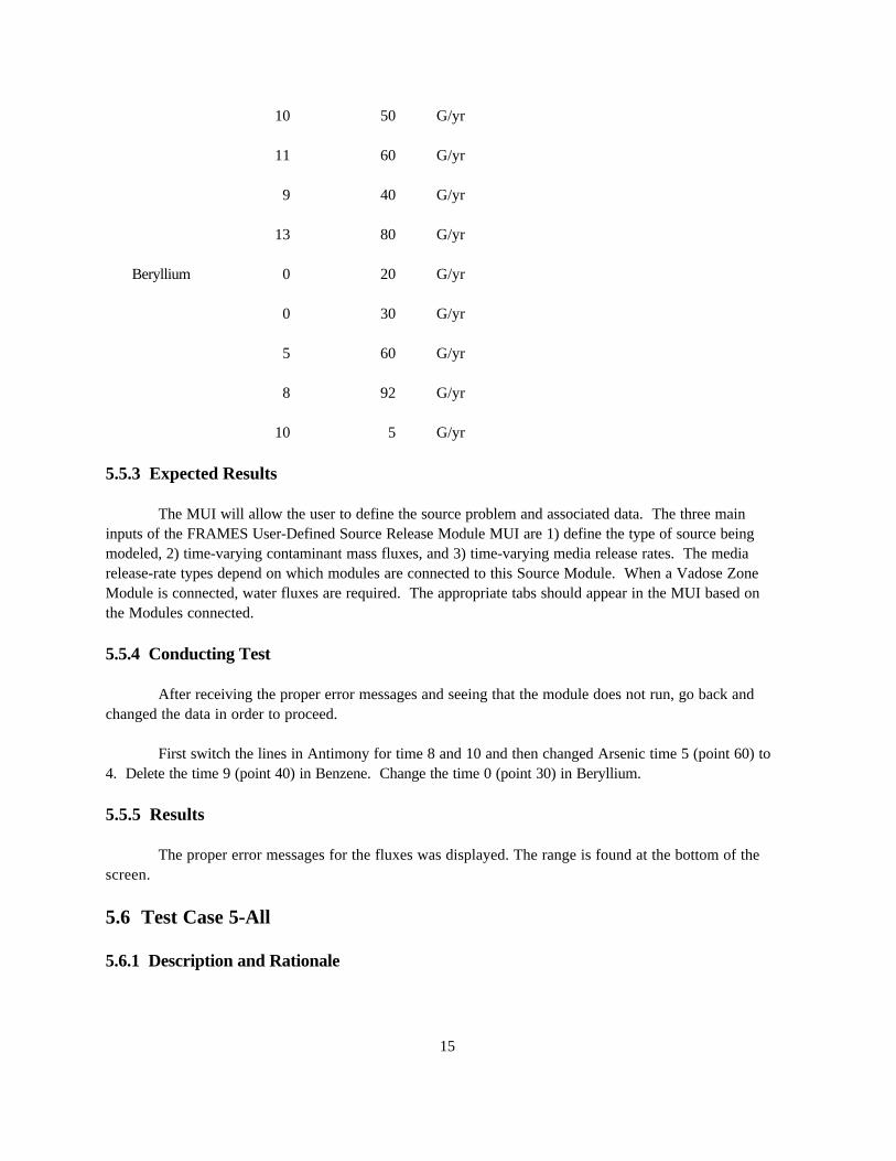
5.5.3 Expected Results
The MUI will allow the user to define the source problem and associated data. The three maininputs of the FRAMES User-Defined Source Release Module MUI are 1) define the type of source beingmodeled, 2) time-varying contaminant mass fluxes, and 3) time-varying media release rates. The mediarelease-rate types depend on which modules are connected to this Source Module. When a Vadose ZoneModule is connected, water fluxes are required. The appropriate tabs should appear in the MUI based onthe Modules connected.
5.5.4 Conducting Test
After receiving the proper error messages and seeing that the module does not run, go back andchanged the data in order to proceed.
First switch the lines in Antimony for time 8 and 10 and then changed Arsenic time 5 (point 60) to4. Delete the time 9 (point 40) in Benzene. Change the time 0 (point 30) in Beryllium.
5.5.5 Results
The proper error messages for the fluxes was displayed. The range is found at the bottom of thescreen.
5.6 Test Case 5-All
5.6.1 Description and Rationale
16
The online help will be tested to ensure that all links work correctly, all input parameters areaddressed and parameter descriptions are clear, and it can be understood by a typical user. Online help isnot yet developed for this module; therefore, this test was not conducted at this time.
17
6.0 Quality Assurance Program
Updates to the FRAMES technology software system will be developed under a qualityassurance program documented in Gelston et al. (1998). Quality is defined as the capability of thesoftware to meet client needs. Meeting client needs starts with a shared understanding of how thesoftware must perform and continues throughout the software life cycle of design, development, testing,and implementation through attention to details.
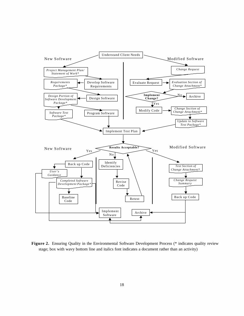
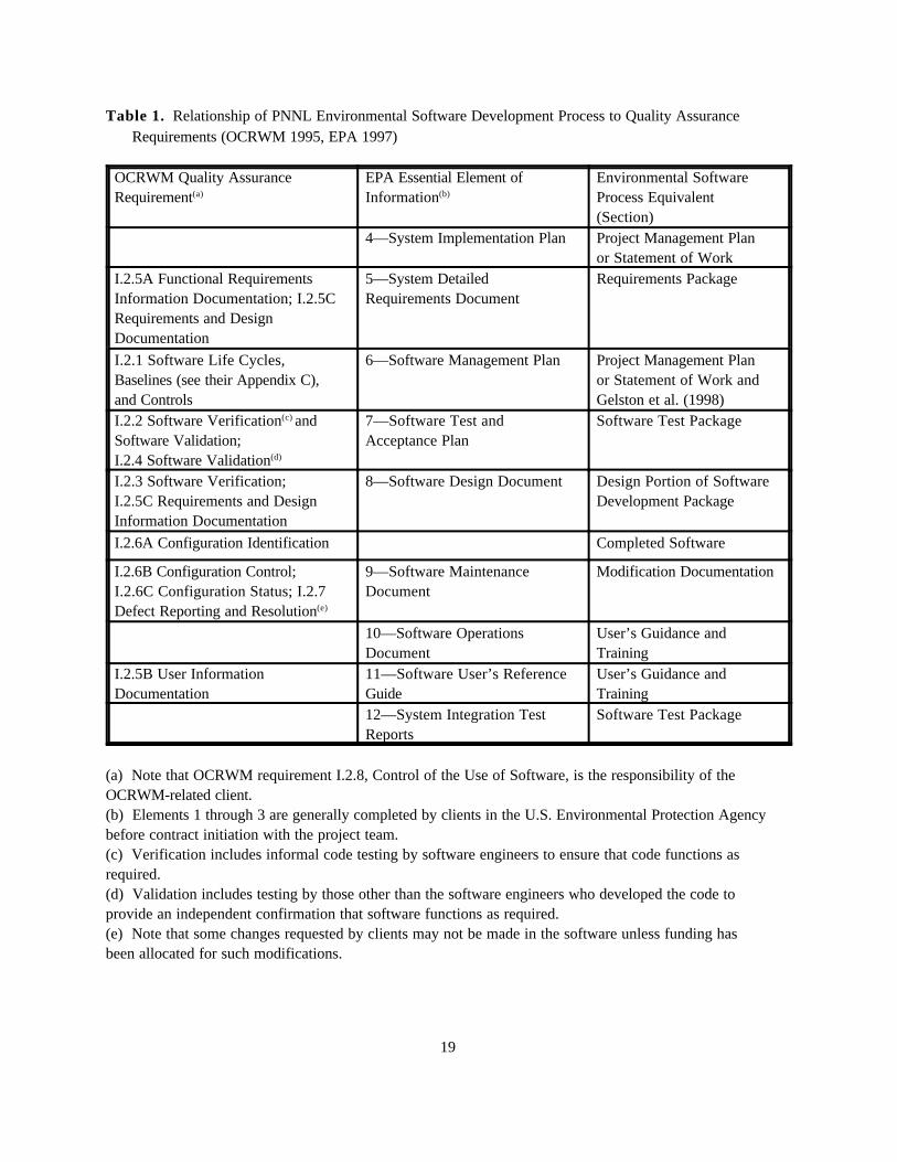
Figure 2 outlines the software-development process that will be used for the FRAMEStechnology software system highlighting the quality check points. The FRAMES technology softwaresystem activities flow down the left side of Figure 3 because it is software developed for the first time asopposed to a modification to existing software. The process shown is designed for compatibility withsimilar processes used by other government agencies. For example, this quality process comparesfavorably with that in EPA Directive 2182, System Design and Development Guidance (EPA 1997). Italso compares favorably with the Office of Civilian Radioactive Waste Management’s QualityAssurance Requirements and Description, Supplement I, Software (OCRWM 1995). Activitiesroughly equivalent across these processes are shown in Table 1.
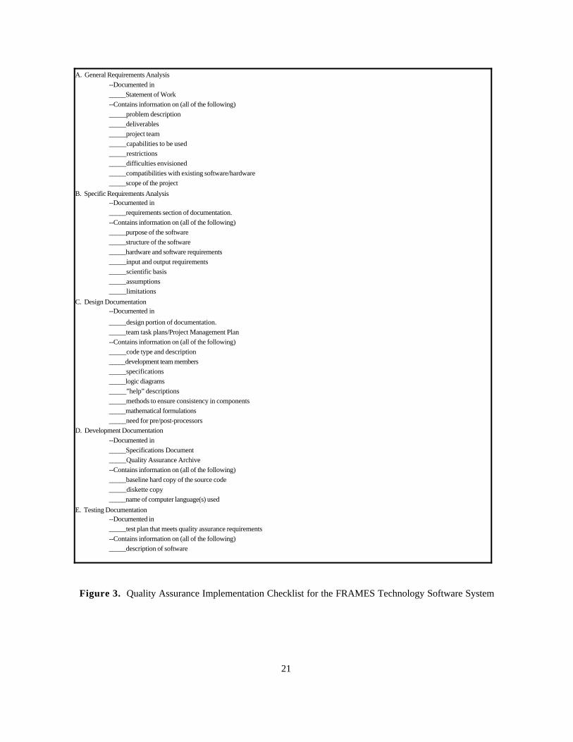
Development of the FRAMES technology software system includes the implementation of aquality assurance checklist (see Figure 3). All team members understand the component requirementsand design necessary to ensure quality. Completion of this checklist verifies that all documentation will becomplete for transfer of the software to client use.
18
Understand Client Needs
Project Management Plan/Statement of Work*
Change Request
New Sof tware Modif ied Sof tware
Develop SoftwareRequirements
RequirementsPackage*
Design SoftwareDesign Portion of
Software DevelopmentPackage*
Program SoftwareSoftware TestPackage*
Results Acceptable?
Evaluate Request Evaluation Section of Change Attachment*
ImplementChange? Archive
Modify CodeChange Section of
Change Attachment*
Update to SoftwareTest Package*
Implement Test Plan
No
Yes
New Sof tware Modif ied Sof tware
IdentifyDeficiencies
ReviseCode
Retest
NoYes Yes
Back up Code
User’sGuidance
Completed SoftwareDevelopment Package*
ImplementSoftware
BaselineCode
Archive
Test Section ofChange Attachment*
Change RequestSummary
Back up Code
Figure 2. Ensuring Quality in the Environmental Software Development Process (* indicates quality reviewstage; box with wavy bottom line and italics font indicates a document rather than an activity)
19
Table 1. Relationship of PNNL Environmental Software Development Process to Quality AssuranceRequirements (OCRWM 1995, EPA 1997)
OCRWM Quality AssuranceRequirement(a)
EPA Essential Element ofInformation(b)
Environmental SoftwareProcess Equivalent(Section)
4—System Implementation Plan Project Management Planor Statement of Work
I.2.5A Functional RequirementsInformation Documentation; I.2.5CRequirements and DesignDocumentation
5—System DetailedRequirements Document
Requirements Package
I.2.1 Software Life Cycles,Baselines (see their Appendix C),and Controls
6—Software Management Plan Project Management Planor Statement of Work andGelston et al. (1998)
I.2.2 Software Verification(c) andSoftware Validation; I.2.4 Software Validation(d)
7—Software Test andAcceptance Plan
Software Test Package
I.2.3 Software Verification; I.2.5C Requirements and DesignInformation Documentation
8—Software Design Document Design Portion of SoftwareDevelopment Package
I.2.6A Configuration Identification Completed Software
I.2.6B Configuration Control;I.2.6C Configuration Status; I.2.7Defect Reporting and Resolution(e)
9—Software MaintenanceDocument
Modification Documentation
10—Software OperationsDocument
User’s Guidance andTraining
I.2.5B User InformationDocumentation
11—Software User’s ReferenceGuide
User’s Guidance andTraining
12—System Integration TestReports
Software Test Package
(a) Note that OCRWM requirement I.2.8, Control of the Use of Software, is the responsibility of theOCRWM-related client.(b) Elements 1 through 3 are generally completed by clients in the U.S. Environmental Protection Agencybefore contract initiation with the project team.(c) Verification includes informal code testing by software engineers to ensure that code functions asrequired.(d) Validation includes testing by those other than the software engineers who developed the code toprovide an independent confirmation that software functions as required.(e) Note that some changes requested by clients may not be made in the software unless funding hasbeen allocated for such modifications.

20
21
A. General Requirements Analysis--Documented in _____Statement of Work--Contains information on (all of the following)_____problem description_____deliverables_____project team_____capabilities to be used_____restrictions_____difficulties envisioned_____compatibilities with existing software/hardware_____scope of the project
B. Specific Requirements Analysis--Documented in _____requirements section of documentation.--Contains information on (all of the following)_____purpose of the software_____structure of the software_____hardware and software requirements_____input and output requirements_____scientific basis_____assumptions_____limitations
C. Design Documentation--Documented in
_____design portion of documentation._____team task plans/Project Management Plan --Contains information on (all of the following)_____code type and description_____development team members_____specifications_____logic diagrams_____”help” descriptions_____methods to ensure consistency in components_____mathematical formulations_____need for pre/post-processors
D. Development Documentation--Documented in _____Specifications Document _____Quality Assurance Archive --Contains information on (all of the following)_____baseline hard copy of the source code_____diskette copy_____name of computer language(s) used
E. Testing Documentation--Documented in_____test plan that meets quality assurance requirements--Contains information on (all of the following)_____description of software
Figure 3. Quality Assurance Implementation Checklist for the FRAMES Technology Software System
22
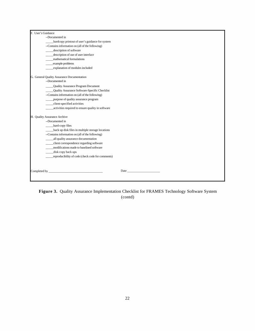
F. User’s Guidance--Documented in _____hardcopy printout of user’s guidance for system--Contains information on (all of the following)_____description of software_____description of use of user interface_____mathematical formulations_____example problems_____explanation of modules included
G. General Quality Assurance Documentation--Documented in
_____Quality Assurance Program Document_____Quality Assurance Software-Specific Checklist--Contains information on (all of the following)_____purpose of quality assurance program_____client-specified activities_____activities required to ensure quality in software
H. Quality Assurance Archive--Documented in _____hard-copy files _____back up disk files in multiple storage locations --Contains information on (all of the following)_____all quality assurance documentation_____client correspondence regarding software_____modifications made to baselined software_____disk copy back ups_____reproducibility of code (check code for comments)
Completed by ___________________________________ Date _____________________
Figure 3. Quality Assurance Implementation Checklist for FRAMES Technology Software System(contd)
23
7.0 References
Gelston, G. M., R. E. Lundgren, J. P. McDonald, and B. L. Hoopes. 1998. An Approach to EnsuringQuality in Environmental Software, PNNL-11880, Pacific Northwest National Laboratory, Richland,Washington.
Office of Civilian Radioactive Waste Management (OCRWM). 1995. Quality AssuranceRequirements and Description, Supplement I, Software, U.S. Department of Energy, Washington,D.C.
U.S. Environmental Protection Agency (EPA). 1997. System Design and Development Guidance,EPA Directive Number 2182, Washington, D.C.
Whelan, G., K. J. Castleton, J. W. Buck, G. M. Gelston, B. L. Hoopes, M. A. Pelton, D. L. Strenge, andR. N. Kickert. 1997. Concepts of a Framework for Risk Analysis in Multimedia EnvironmentalSystems (FRAMES), PNNL-11748, Pacific Northwest National Laboratory, Richland, Washington.
Appendix A
General Procedure for Test Case Implementation
A.1
Appendix A: General Procedure for Test Case Implementation
Open the Multimedia Framework (fui.exe). Select New from the File menu. Enter a file nameand slect Open. Enter a site name at the prompt and select Ok.
Click on the contaminant icon. The icon will appear on the work screen. Click and hold on aSource Term icon; pull it down into the work screen. Choose the desired icons to complete your case andrepeat, dragging them down onto the work screen. When all icons are in place, connect the iconstogether. To do this, hold down the shift key, click on an icon, and drag the mouse to the next icon. Release shift and mouse button. A line will connect the two icons with an arrow pointing from the firsticon clicked on to the second icon. To remove this line, repeat the steps used to connect it. Continuelinking all icons together, moving from left to right across the screen so that the arrows are pointing in theright direction and starting with the Source Term icon, not the contaminant icon. To remove an icon fromthe screen, drag it to the trash can located on the tool bar. An icon can have more than one arrowcoming from it to different icons (i.e., the source icon can have two of the graph icons attached to it withone set as a chart and the other as a viewer).
Right click on the contaminant icon and choose General Info. When the General Info screenopens, select Label: Contaminants and Module: FRAMES Default Chemical Database Selection. Clickon OK at the bottom of the screen; this returns you to the work area, and the signal light attached to thecontaminant icon changes from black into red. Right click on the contaminant icon in the work space andchoose User Input on the box that appears and the Contaminant Selection screen will open. Select fromPossible Contaminants: All Contaminants. Scroll to select the contaminants or use the Find option on thisscreen. Click OK to return to the work screen. The light will change from red into green.
Right click on the Source Term icon on the work area and choose General Info. Choose Label:Source and Module: FRAMES Known Contaminant Flux or Concentration. Click OK. The signal lightwill turn from black into red.
Right click on the Source Term icon and choose User Input, and the FRAMES Known SourceModule screen will open. In the source icon under Atmospheric Release Flux Types, do not change anyinformation; just use the automatic information and click done.
If the progeny is not showing up on the screen when the parent is chosen, click on Options:Choose Progeny. A check mark will appear by this option. To turn off this option, click on ChooseProgeny again. Fill in the red boxes on the Atmospheric Flux tab. On all the tabs, fill in the red boxes. These boxes will turn to green when the correct information is entered. For guidance on what to enter inthe red boxes, click on one of the boxes and look at the scrolling bar at the bottom of the screen. This barwill give you the boundaries for the box. If more guidance is needed, choose the desired box by clickingon it and press F1. This will open up the online help that will take you directly to the correct section.
Click save and exit; the light will turn from red into yellow.
A.2
For each test case, follow the above steps. After these first steps have been followed, continueto build the case using user-input information and the same steps used to fill in the information on theSource Term icon. When the test case has been built, and you are ready for the results, follow theseinstructions.
Right click on Source and choose Run Model. The model will run, and the light will change fromYellow into Green. Right click on the next icon and choose Run Model. The model will run, and the lightwill change from Yellow into Green. Instead of running each model individually, click on the GO button inthe toolbar at the top of the screen. This button works if all the lights are yellow. If one is black or redand you wish to leave it this way, then you will have to run each model separately.
To view results, right click on the Source Term icon, and select the desired viewer from theView/Print Module Output. To display a different viewer, exit the open viewer and reselect a differentviewer from the menu.