Embed Size (px)
Citation preview
Robustness assessment of a steel self-centering moment-resisting
frame under column loss
George Vasdravellis; Marco Baiguera; Dina Al-Sammaraie
Institute for Infrastructure and Environment, Heriot-Watt University, UK
Emails: [email protected], [email protected], [email protected]
Abstract. The robustness of a seismically-designed steel self-centering moment-resisting frame (SC-
MRF) under a column loss scenario is numerically assessed. The prototype SC-MRF is equipped with
post-tensioned bars and optimised stainless steel energy dissipation devices. The SC-MRF was
modelled in full detail using solid finite elements. The numerical model was calibrated using results
from previous tests on post-tensioned beam-column connections and isolated component tests on the
energy dissipation devices. Quasi-static analyses were carried out to identify the failure modes of the
SC-MRF under a column loss scenario. Nonlinear dynamic analyses were also performed to evaluate
the dynamic response of the frame and to assess the acceptance criteria against progressive collapse
according to the current codes of practice. The results show that the SC-MRF has superior robustness
and it can guarantee a high level of safety under a sudden column loss scenario due to the high fracture
capacity of the stainless steel energy dissipation devices and the tie force resistance provided by the
post-tensioned bars.
2
1 INTRODUCTION
In the last decades, many buildings around the world experienced progressive collapse due to extreme
loading conditions that resulted in the loss of one or more columns. Progressive collapse of a building
has catastrophic consequences, and so, there is a growing interest to design buildings with increased
robustness so that they can arrest the sudden loss of one or more bearing elements. Eurocode 1, Part
1-7 [1] stipulates the use of the Tie Force method to mitigate the consequences of a localised failure
in buildings from an unspecified cause. However, the rules given are not specific for a structural type
and no guidance is provided on the analysis type that should be performed, i.e. linear or nonlinear, or
on the consideration of the dynamic effects of the loading. In the USA, the General Services
Administration (GSA) [2] and the Unified Facilities Criteria (UFC) 4-023-23 [3] give more
systematic procedures and specific acceptance criteria for designing buildings against progressive
collapse. The GSA document requires that buildings should be assessed against progressive collapse
using the Alternate Load Path (ALP) method and gives specific rules for modelling and acceptance
criteria for each structural type. The UFC guidelines require the use of three design strategies,
depending on the building category: the Tie Force method, the ALP method and the Enhanced Local
Resistance method. Both GSA and UFC guidelines permit linear or nonlinear static analysis to be
performed using a Dynamic Increase Factor (DIF) to account for the inertia effects.
Experimental studies on the progressive collapse of steel and steel-concrete composite frames
include large-scale laboratory tests on two-dimensional frame sub-assemblies [4], tests on three-
dimensional steel and composite sub-assemblies [5]–[8], and column removal tests on steel buildings
[9], [10]. The studies by Yang and Tan [11-12], and Wang et al. [13] focused on the behaviour of
steel and composite beam-column connections under the effects of catenary action imposed by
progressive collapse. Numerical studies on the progressive collapse behaviour of steel and composite
frames using the finite element method (FEM) include the study of the effects of the composite floor
on the collapse behaviour of buildings [14]–[17], three-dimensional simulations of multi-story
buildings and investigation of the role of the gravity system on the robustness of frames [18]–[21],
3
and numerical studies focused on the effect of beam-column connections on the collapse resistance
[22]–[24]. Analytical assessment methods for progressive collapse were proposed in [25]–[28].
Steel self-centering moment-resisting frames (SC-MRFs) are a recently developed type of
seismic-resistant frames that are able to provide increased resilience under strong earthquakes. Post-
tensioned (PT) bars are used to clamp the beams to the columns and allow a gap to open and close at
the beam-column interface under lateral loading of the building. The restoring forces produced by the
elastic elongation of the PT bars provide self-centering capability, eliminating the residual drifts after
a strong seismic event. The use of energy dissipation devices (EDs) at the beam-column interfaces
increases the energy dissipation capacity of the structure. Moreover, the EDs can be designed to be
easily replaceable, thus minimising the downtime for the building repair. Several configurations of
SC-MRFs were proposed, with the main difference being the type of the EDs. Examples include steel
yielding EDs such as those proposed in [29]–[35], and friction-based EDs, such as those proposed in
[36]–[40].
Despite the relatively large body of research on the seismic behaviour of SC-MRFs, their
progressive collapse behaviour is not yet studied thoroughly. Tsitos et al. [41] tested experimentally
the collapse of a frame using PT connections and steel yielding bars as EDs. Pirmoz and Liu [42]
carried out FEM analyses on the same frame. The frames in those studies had only two bays and small
beam spans (1.219 m and 3 m), and thus the collapse of the frames in a sudden column loss scenario
was dictated by the early PT bar fracture.
This paper presents a numerical study on the behaviour of an SC-MRF under a column loss
scenario. The SC-MRF is part of a seismically designed five-storey prototype frame and uses stainless
steel hourglass-shape yielding EDs, denoted as web hourglass pins (WHPs), which possess very high
ductility [43]. The planar frame was reproduced in the simulations in full detail using solid finite
elements. The fracture capacity of the WHPs was calibrated using experimental data from tests
performed specifically on these devices in [43]. Quasi-static analyses were carried out to identify the
failure modes of the SC-MRF under a sudden column loss scenario. Nonlinear dynamic (NL) analyses
4
were also performed to evaluate the dynamic response of the SC-MRF and to assess the acceptance
criteria according to the UFC guidelines [3].
2 PROTOTYPE STEEL SELF-CENTERING MOMENT-RESISTING FRAME
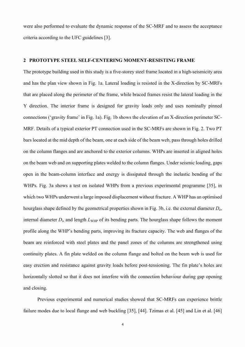
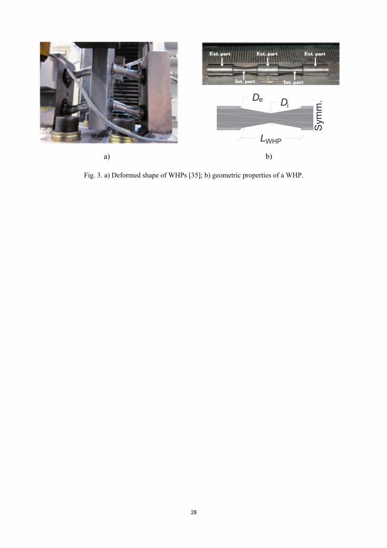
The prototype building used in this study is a five-storey steel frame located in a high-seismicity area
and has the plan view shown in Fig. 1a. Lateral loading is resisted in the X-direction by SC-MRFs
that are placed along the perimeter of the frame, while braced frames resist the lateral loading in the
Y direction. The interior frame is designed for gravity loads only and uses nominally pinned
connections (‘gravity frame’ in Fig. 1a). Fig. 1b shows the elevation of an X-direction perimeter SC-
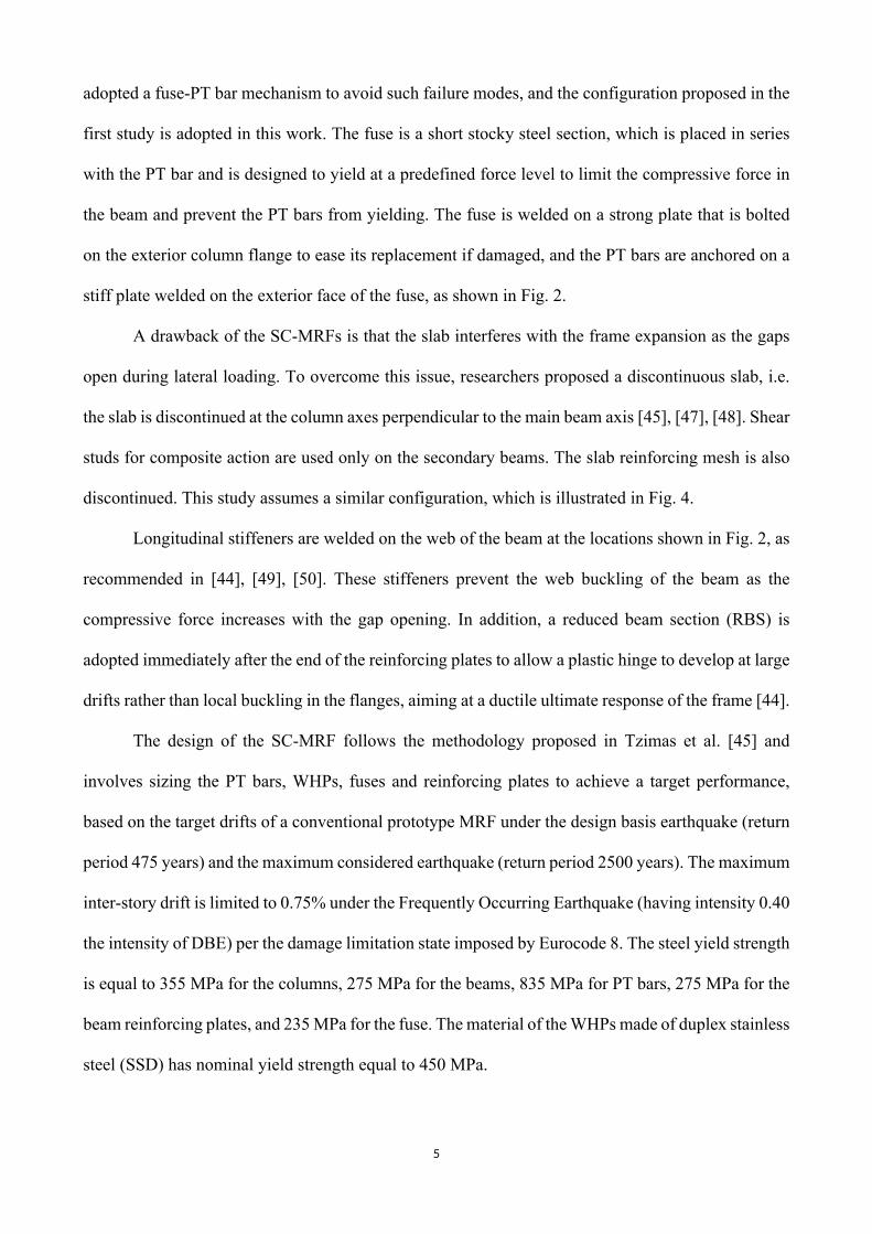
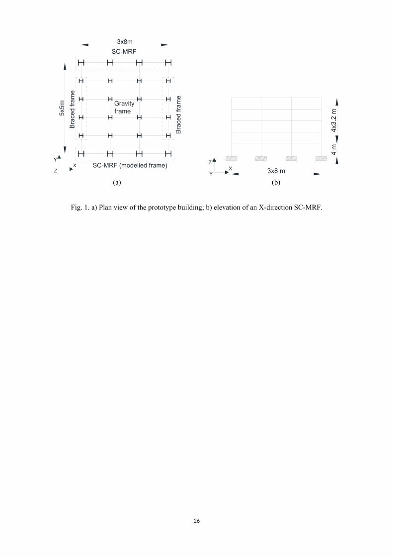
MRF. Details of a typical exterior PT connection used in the SC-MRFs are shown in Fig. 2. Two PT
bars located at the mid depth of the beam, one at each side of the beam web, pass through holes drilled
on the column flanges and are anchored to the exterior columns. WHPs are inserted in aligned holes
on the beam web and on supporting plates welded to the column flanges. Under seismic loading, gaps
open in the beam-column interface and energy is dissipated through the inelastic bending of the
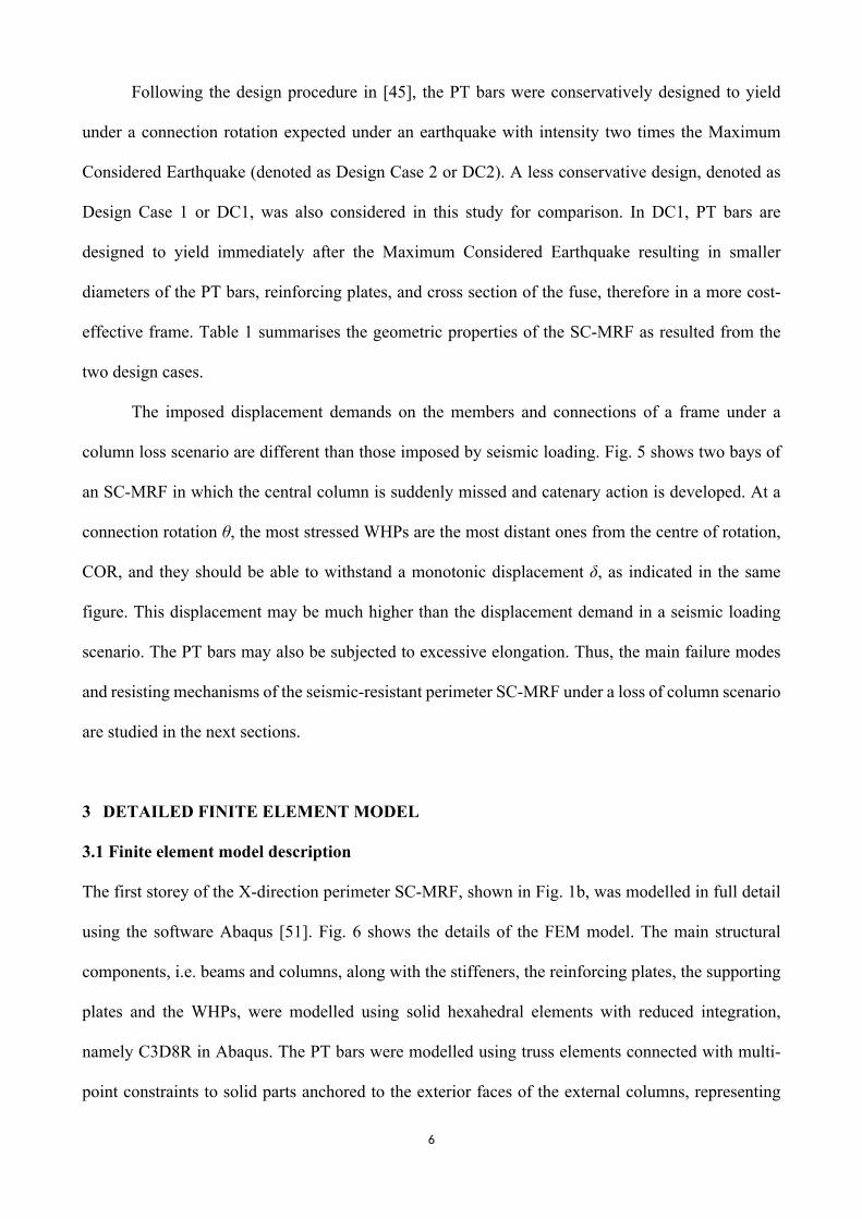
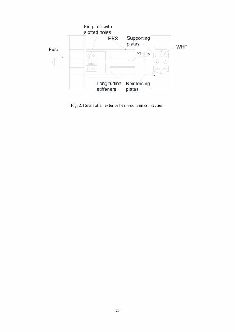
WHPs. Fig. 3a shows a test on isolated WHPs from a previous experimental programme [35], in
which two WHPs underwent a large imposed displacement without fracture. A WHP has an optimised
hourglass shape defined by the geometrical properties shown in Fig. 3b, i.e. the external diameter De,
internal diameter Di, and length LWHP of its bending parts. The hourglass shape follows the moment
profile along the WHP’s bending parts, improving its fracture capacity. The web and flanges of the
beam are reinforced with steel plates and the panel zones of the columns are strengthened using
continuity plates. A fin plate welded on the column flange and bolted on the beam web is used for
easy erection and resistance against gravity loads before post-tensioning. The fin plate’s holes are
horizontally slotted so that it does not interfere with the connection behaviour during gap opening
and closing.
Previous experimental and numerical studies showed that SC-MRFs can experience brittle
failure modes due to local flange and web buckling [35], [44]. Tzimas et al. [45] and Lin et al. [46]
5
adopted a fuse-PT bar mechanism to avoid such failure modes, and the configuration proposed in the
first study is adopted in this work. The fuse is a short stocky steel section, which is placed in series
with the PT bar and is designed to yield at a predefined force level to limit the compressive force in
the beam and prevent the PT bars from yielding. The fuse is welded on a strong plate that is bolted
on the exterior column flange to ease its replacement if damaged, and the PT bars are anchored on a
stiff plate welded on the exterior face of the fuse, as shown in Fig. 2.
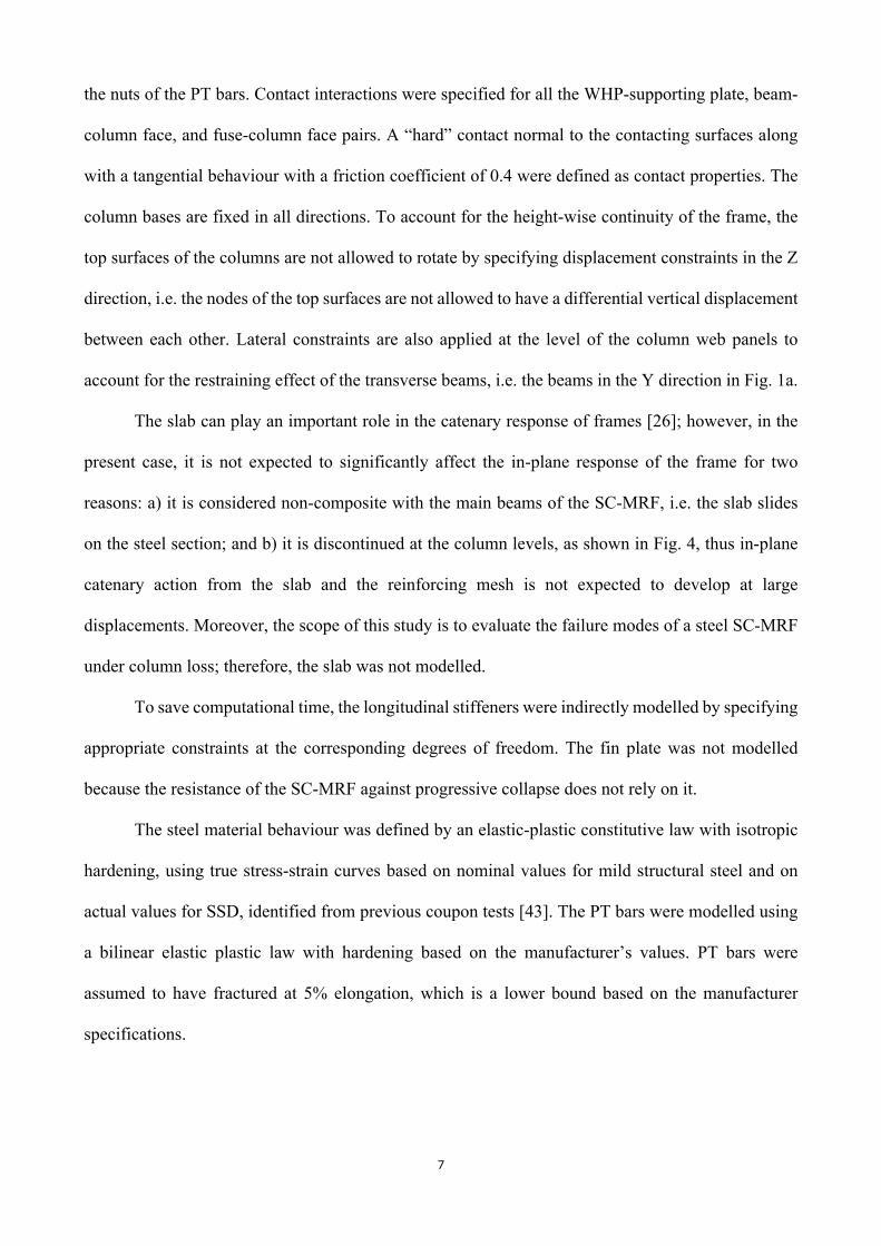
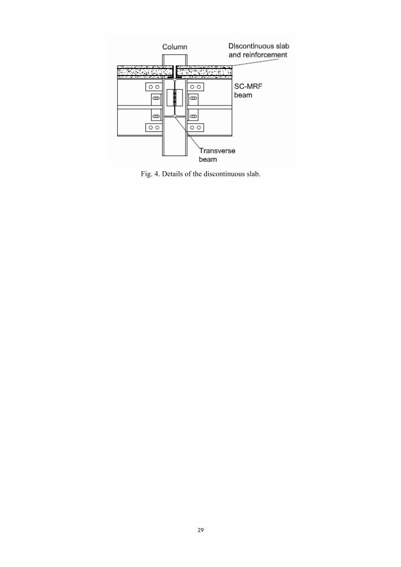
A drawback of the SC-MRFs is that the slab interferes with the frame expansion as the gaps
open during lateral loading. To overcome this issue, researchers proposed a discontinuous slab, i.e.
the slab is discontinued at the column axes perpendicular to the main beam axis [45], [47], [48]. Shear
studs for composite action are used only on the secondary beams. The slab reinforcing mesh is also
discontinued. This study assumes a similar configuration, which is illustrated in Fig. 4.
Longitudinal stiffeners are welded on the web of the beam at the locations shown in Fig. 2, as
recommended in [44], [49], [50]. These stiffeners prevent the web buckling of the beam as the
compressive force increases with the gap opening. In addition, a reduced beam section (RBS) is
adopted immediately after the end of the reinforcing plates to allow a plastic hinge to develop at large
drifts rather than local buckling in the flanges, aiming at a ductile ultimate response of the frame [44].
The design of the SC-MRF follows the methodology proposed in Tzimas et al. [45] and
involves sizing the PT bars, WHPs, fuses and reinforcing plates to achieve a target performance,
based on the target drifts of a conventional prototype MRF under the design basis earthquake (return
period 475 years) and the maximum considered earthquake (return period 2500 years). The maximum
inter-story drift is limited to 0.75% under the Frequently Occurring Earthquake (having intensity 0.40
the intensity of DBE) per the damage limitation state imposed by Eurocode 8. The steel yield strength
is equal to 355 MPa for the columns, 275 MPa for the beams, 835 MPa for PT bars, 275 MPa for the
beam reinforcing plates, and 235 MPa for the fuse. The material of the WHPs made of duplex stainless
steel (SSD) has nominal yield strength equal to 450 MPa.
6
Following the design procedure in [45], the PT bars were conservatively designed to yield
under a connection rotation expected under an earthquake with intensity two times the Maximum
Considered Earthquake (denoted as Design Case 2 or DC2). A less conservative design, denoted as
Design Case 1 or DC1, was also considered in this study for comparison. In DC1, PT bars are
designed to yield immediately after the Maximum Considered Earthquake resulting in smaller
diameters of the PT bars, reinforcing plates, and cross section of the fuse, therefore in a more cost-
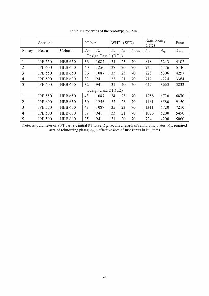
effective frame. Table 1 summarises the geometric properties of the SC-MRF as resulted from the
two design cases.
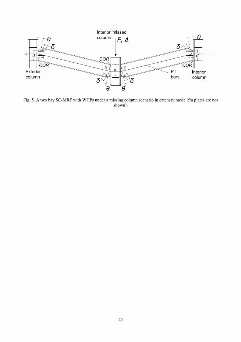
The imposed displacement demands on the members and connections of a frame under a
column loss scenario are different than those imposed by seismic loading. Fig. 5 shows two bays of
an SC-MRF in which the central column is suddenly missed and catenary action is developed. At a
connection rotation θ, the most stressed WHPs are the most distant ones from the centre of rotation,
COR, and they should be able to withstand a monotonic displacement δ, as indicated in the same
figure. This displacement may be much higher than the displacement demand in a seismic loading
scenario. The PT bars may also be subjected to excessive elongation. Thus, the main failure modes
and resisting mechanisms of the seismic-resistant perimeter SC-MRF under a loss of column scenario
are studied in the next sections.
3 DETAILED FINITE ELEMENT MODEL
3.1 Finite element model description
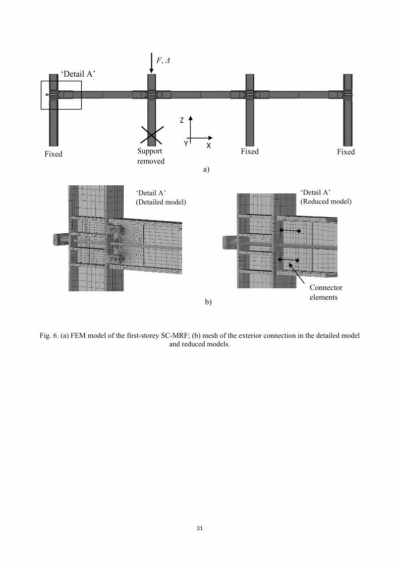
The first storey of the X-direction perimeter SC-MRF, shown in Fig. 1b, was modelled in full detail
using the software Abaqus [51]. Fig. 6 shows the details of the FEM model. The main structural
components, i.e. beams and columns, along with the stiffeners, the reinforcing plates, the supporting
plates and the WHPs, were modelled using solid hexahedral elements with reduced integration,
namely C3D8R in Abaqus. The PT bars were modelled using truss elements connected with multi-
point constraints to solid parts anchored to the exterior faces of the external columns, representing
7
the nuts of the PT bars. Contact interactions were specified for all the WHP-supporting plate, beam-
column face, and fuse-column face pairs. A “hard” contact normal to the contacting surfaces along
with a tangential behaviour with a friction coefficient of 0.4 were defined as contact properties. The
column bases are fixed in all directions. To account for the height-wise continuity of the frame, the
top surfaces of the columns are not allowed to rotate by specifying displacement constraints in the Z
direction, i.e. the nodes of the top surfaces are not allowed to have a differential vertical displacement
between each other. Lateral constraints are also applied at the level of the column web panels to
account for the restraining effect of the transverse beams, i.e. the beams in the Y direction in Fig. 1a.
The slab can play an important role in the catenary response of frames [26]; however, in the
present case, it is not expected to significantly affect the in-plane response of the frame for two
reasons: a) it is considered non-composite with the main beams of the SC-MRF, i.e. the slab slides
on the steel section; and b) it is discontinued at the column levels, as shown in Fig. 4, thus in-plane
catenary action from the slab and the reinforcing mesh is not expected to develop at large
displacements. Moreover, the scope of this study is to evaluate the failure modes of a steel SC-MRF
under column loss; therefore, the slab was not modelled.
To save computational time, the longitudinal stiffeners were indirectly modelled by specifying
appropriate constraints at the corresponding degrees of freedom. The fin plate was not modelled
because the resistance of the SC-MRF against progressive collapse does not rely on it.
The steel material behaviour was defined by an elastic-plastic constitutive law with isotropic
hardening, using true stress-strain curves based on nominal values for mild structural steel and on
actual values for SSD, identified from previous coupon tests [43]. The PT bars were modelled using
a bilinear elastic plastic law with hardening based on the manufacturer’s values. PT bars were
assumed to have fractured at 5% elongation, which is a lower bound based on the manufacturer
specifications.
8
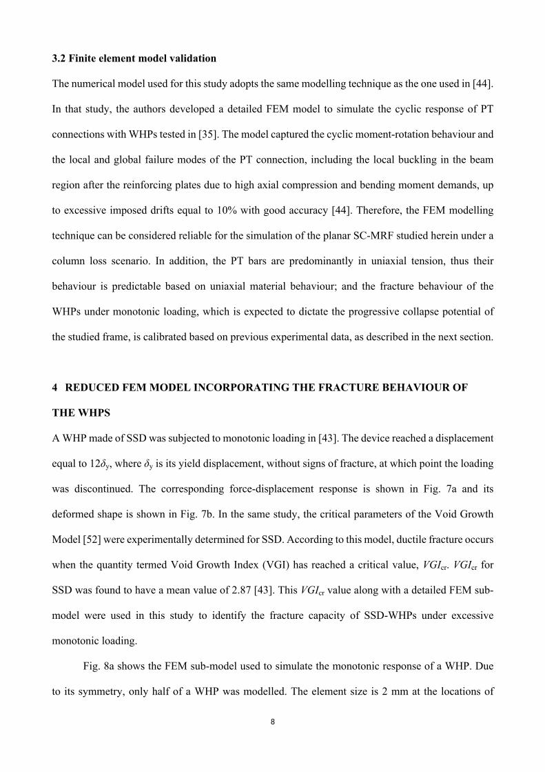
3.2 Finite element model validation
The numerical model used for this study adopts the same modelling technique as the one used in [44].
In that study, the authors developed a detailed FEM model to simulate the cyclic response of PT
connections with WHPs tested in [35]. The model captured the cyclic moment-rotation behaviour and
the local and global failure modes of the PT connection, including the local buckling in the beam
region after the reinforcing plates due to high axial compression and bending moment demands, up
to excessive imposed drifts equal to 10% with good accuracy [44]. Therefore, the FEM modelling
technique can be considered reliable for the simulation of the planar SC-MRF studied herein under a
column loss scenario. In addition, the PT bars are predominantly in uniaxial tension, thus their
behaviour is predictable based on uniaxial material behaviour; and the fracture behaviour of the
WHPs under monotonic loading, which is expected to dictate the progressive collapse potential of
the studied frame, is calibrated based on previous experimental data, as described in the next section.
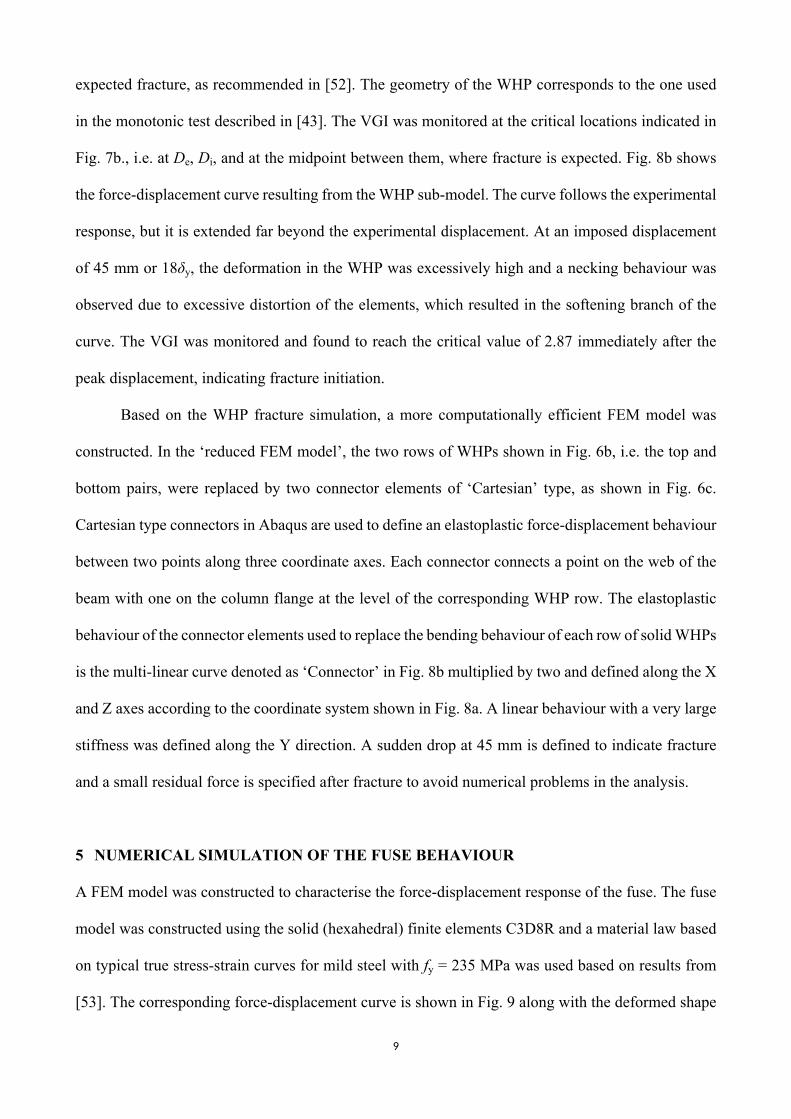
4 REDUCED FEM MODEL INCORPORATING THE FRACTURE BEHAVIOUR OF
THE WHPS
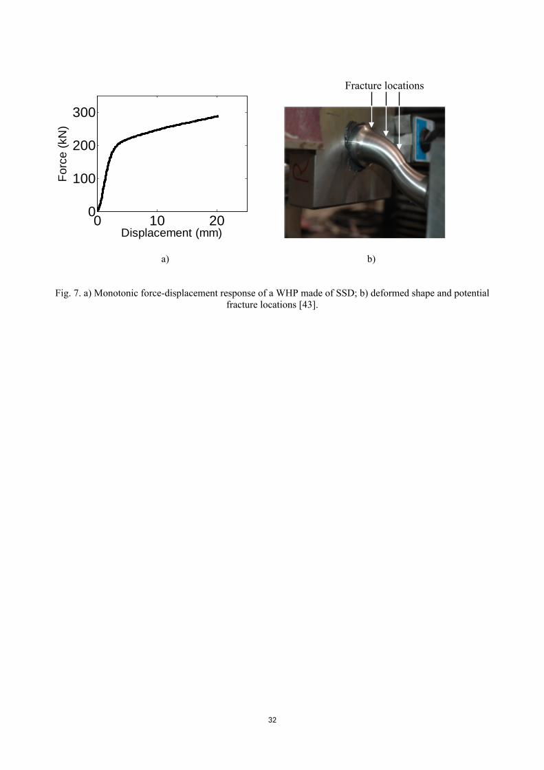
A WHP made of SSD was subjected to monotonic loading in [43]. The device reached a displacement
equal to 12δy, where δy is its yield displacement, without signs of fracture, at which point the loading
was discontinued. The corresponding force-displacement response is shown in Fig. 7a and its
deformed shape is shown in Fig. 7b. In the same study, the critical parameters of the Void Growth
Model [52] were experimentally determined for SSD. According to this model, ductile fracture occurs
when the quantity termed Void Growth Index (VGI) has reached a critical value, VGIcr. VGIcr for
SSD was found to have a mean value of 2.87 [43]. This VGIcr value along with a detailed FEM sub-
model were used in this study to identify the fracture capacity of SSD-WHPs under excessive
monotonic loading.
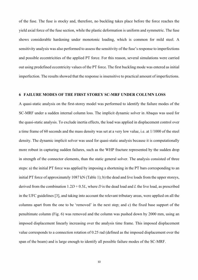
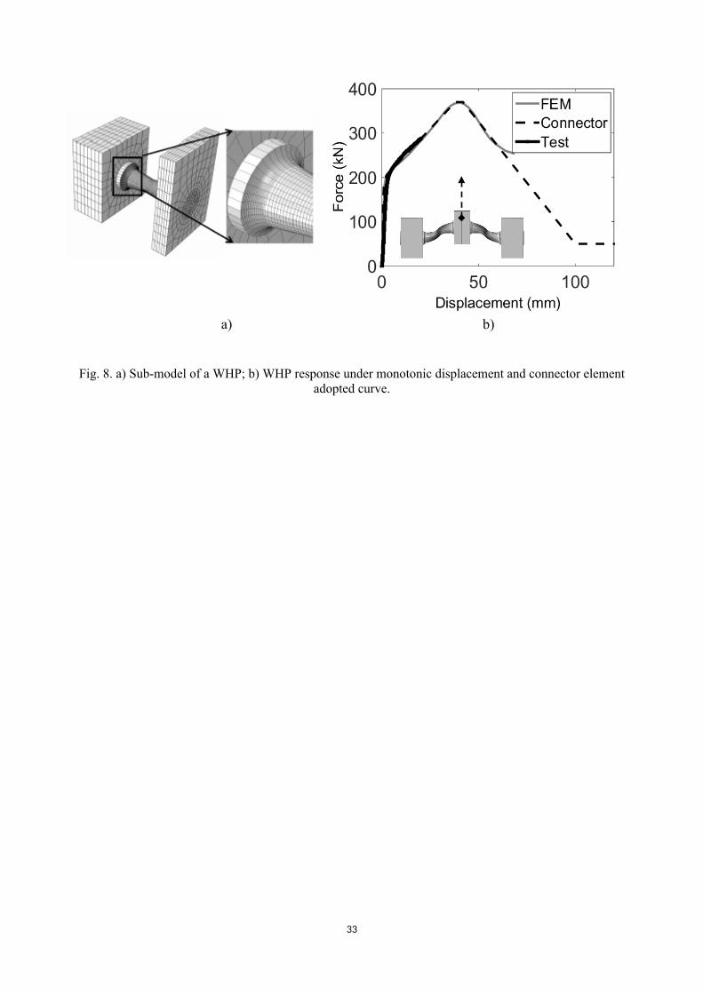
Fig. 8a shows the FEM sub-model used to simulate the monotonic response of a WHP. Due
to its symmetry, only half of a WHP was modelled. The element size is 2 mm at the locations of
9
expected fracture, as recommended in [52]. The geometry of the WHP corresponds to the one used
in the monotonic test described in [43]. The VGI was monitored at the critical locations indicated in
Fig. 7b., i.e. at De, Di, and at the midpoint between them, where fracture is expected. Fig. 8b shows
the force-displacement curve resulting from the WHP sub-model. The curve follows the experimental
response, but it is extended far beyond the experimental displacement. At an imposed displacement
of 45 mm or 18δy, the deformation in the WHP was excessively high and a necking behaviour was
observed due to excessive distortion of the elements, which resulted in the softening branch of the
curve. The VGI was monitored and found to reach the critical value of 2.87 immediately after the
peak displacement, indicating fracture initiation.
Based on the WHP fracture simulation, a more computationally efficient FEM model was
constructed. In the ‘reduced FEM model’, the two rows of WHPs shown in Fig. 6b, i.e. the top and
bottom pairs, were replaced by two connector elements of ‘Cartesian’ type, as shown in Fig. 6c.
Cartesian type connectors in Abaqus are used to define an elastoplastic force-displacement behaviour
between two points along three coordinate axes. Each connector connects a point on the web of the
beam with one on the column flange at the level of the corresponding WHP row. The elastoplastic
behaviour of the connector elements used to replace the bending behaviour of each row of solid WHPs
is the multi-linear curve denoted as ‘Connector’ in Fig. 8b multiplied by two and defined along the X
and Z axes according to the coordinate system shown in Fig. 8a. A linear behaviour with a very large
stiffness was defined along the Y direction. A sudden drop at 45 mm is defined to indicate fracture
and a small residual force is specified after fracture to avoid numerical problems in the analysis.
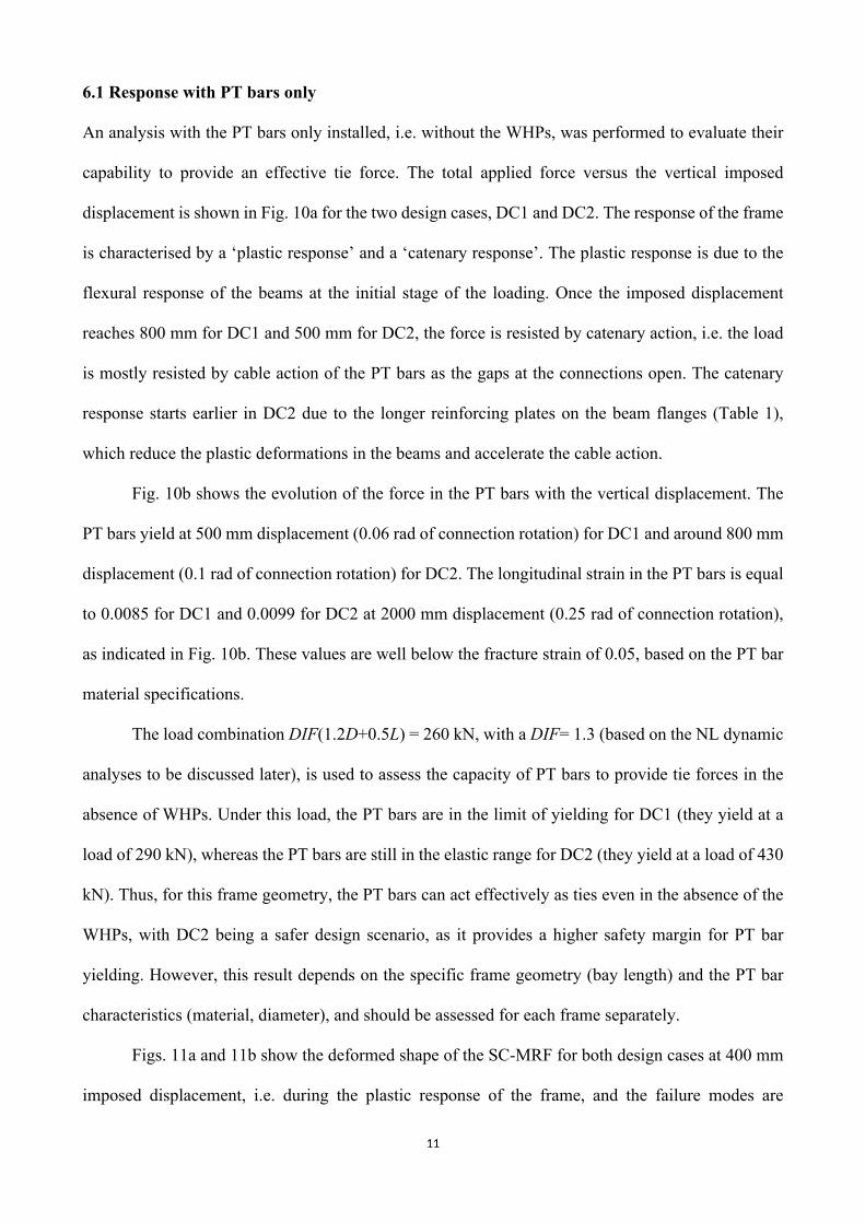
5 NUMERICAL SIMULATION OF THE FUSE BEHAVIOUR
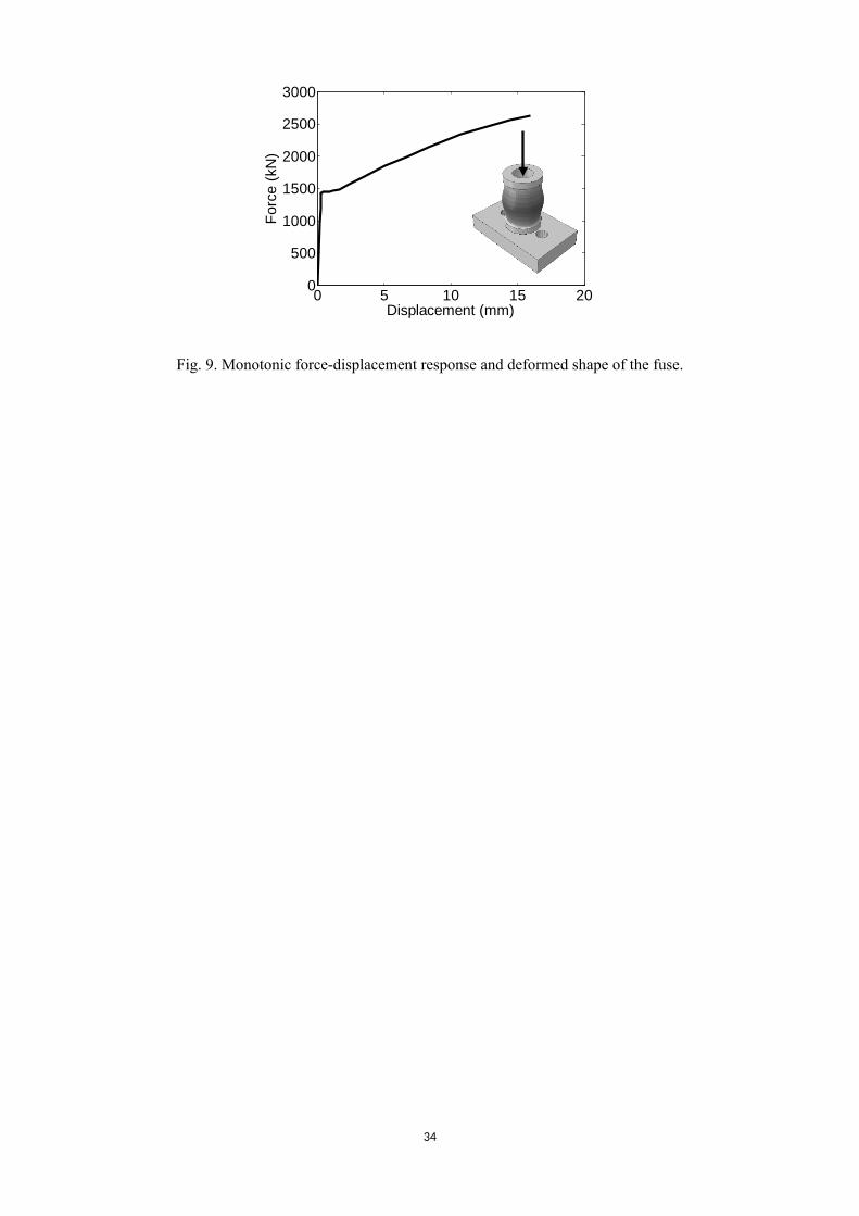
A FEM model was constructed to characterise the force-displacement response of the fuse. The fuse
model was constructed using the solid (hexahedral) finite elements C3D8R and a material law based
on typical true stress-strain curves for mild steel with fy = 235 MPa was used based on results from
[53]. The corresponding force-displacement curve is shown in Fig. 9 along with the deformed shape
10
of the fuse. The fuse is stocky and, therefore, no buckling takes place before the force reaches the
yield axial force of the fuse section, while the plastic deformation is uniform and symmetric. The fuse
shows considerable hardening under monotonic loading, which is common for mild steel. A
sensitivity analysis was also performed to assess the sensitivity of the fuse’s response to imperfections
and possible eccentricities of the applied PT force. For this reason, several simulations were carried
out using predefined eccentricity values of the PT force. The first buckling mode was entered as initial
imperfection. The results showed that the response is insensitive to practical amount of imperfections.
6 FAILURE MODES OF THE FIRST STOREY SC-MRF UNDER COLUMN LOSS
A quasi-static analysis on the first-storey model was performed to identify the failure modes of the
SC-MRF under a sudden internal column loss. The implicit dynamic solver in Abaqus was used for
the quasi-static analysis. To exclude inertia effects, the load was applied in displacement control over
a time frame of 60 seconds and the mass density was set at a very low value, i.e. at 1/1000 of the steel
density. The dynamic implicit solver was used for quasi-static analysis because it is computationally
more robust in capturing sudden failures, such as the WHP fracture represented by the sudden drop
in strength of the connector elements, than the static general solver. The analysis consisted of three
steps: a) the initial PT force was applied by imposing a shortening in the PT bars corresponding to an
initial PT force of approximately 1087 kN (Table 1); b) the dead and live loads from the upper storeys,
derived from the combination 1.2D + 0.5L, where D is the dead load and L the live load, as prescribed
in the UFC guidelines [3], and taking into account the relevant tributary areas, were applied on all the
columns apart from the one to be ‘removed’ in the next step; and c) the fixed base support of the
penultimate column (Fig. 6) was removed and the column was pushed down by 2000 mm, using an
imposed displacement linearly increasing over the analysis time frame. This imposed displacement
value corresponds to a connection rotation of 0.25 rad (defined as the imposed displacement over the
span of the beam) and is large enough to identify all possible failure modes of the SC-MRF.
11
6.1 Response with PT bars only
An analysis with the PT bars only installed, i.e. without the WHPs, was performed to evaluate their
capability to provide an effective tie force. The total applied force versus the vertical imposed
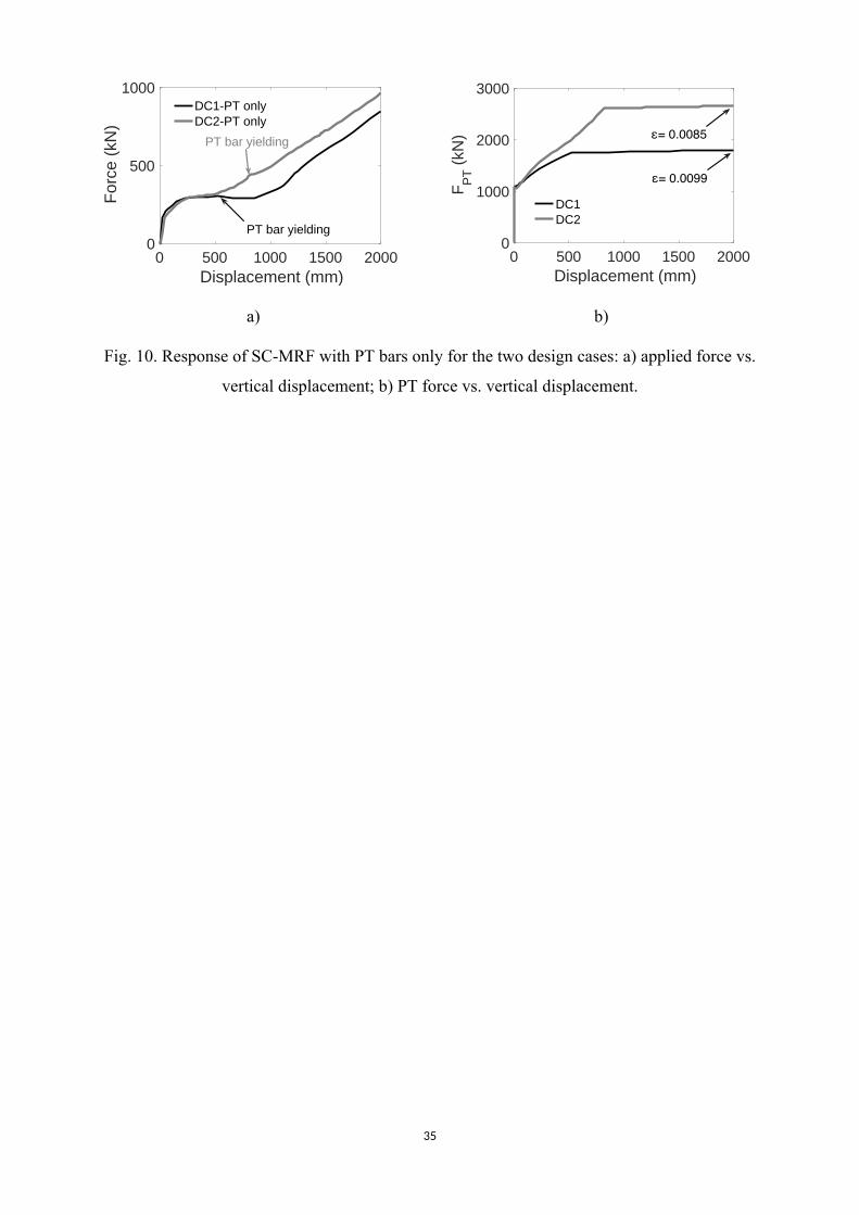
displacement is shown in Fig. 10a for the two design cases, DC1 and DC2. The response of the frame
is characterised by a ‘plastic response’ and a ‘catenary response’. The plastic response is due to the
flexural response of the beams at the initial stage of the loading. Once the imposed displacement
reaches 800 mm for DC1 and 500 mm for DC2, the force is resisted by catenary action, i.e. the load
is mostly resisted by cable action of the PT bars as the gaps at the connections open. The catenary
response starts earlier in DC2 due to the longer reinforcing plates on the beam flanges (Table 1),
which reduce the plastic deformations in the beams and accelerate the cable action.
Fig. 10b shows the evolution of the force in the PT bars with the vertical displacement. The
PT bars yield at 500 mm displacement (0.06 rad of connection rotation) for DC1 and around 800 mm
displacement (0.1 rad of connection rotation) for DC2. The longitudinal strain in the PT bars is equal
to 0.0085 for DC1 and 0.0099 for DC2 at 2000 mm displacement (0.25 rad of connection rotation),
as indicated in Fig. 10b. These values are well below the fracture strain of 0.05, based on the PT bar
material specifications.
The load combination DIF(1.2D+0.5L) = 260 kN, with a DIF= 1.3 (based on the NL dynamic
analyses to be discussed later), is used to assess the capacity of PT bars to provide tie forces in the
absence of WHPs. Under this load, the PT bars are in the limit of yielding for DC1 (they yield at a
load of 290 kN), whereas the PT bars are still in the elastic range for DC2 (they yield at a load of 430
kN). Thus, for this frame geometry, the PT bars can act effectively as ties even in the absence of the
WHPs, with DC2 being a safer design scenario, as it provides a higher safety margin for PT bar
yielding. However, this result depends on the specific frame geometry (bay length) and the PT bar
characteristics (material, diameter), and should be assessed for each frame separately.
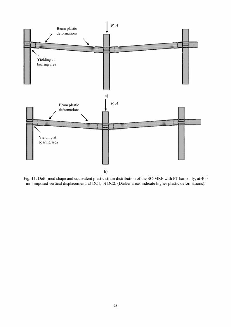
Figs. 11a and 11b show the deformed shape of the SC-MRF for both design cases at 400 mm
imposed displacement, i.e. during the plastic response of the frame, and the failure modes are
12
indicated. The PT bars are still elastic. The plastic region in the beams is more pronounced in DC1
due to the shorter reinforcing plates used on the beam flanges. Plastic deformations at the beam-
column bearing areas develop due to the reduction of the contact area, which results in a stress
concentration at that region.
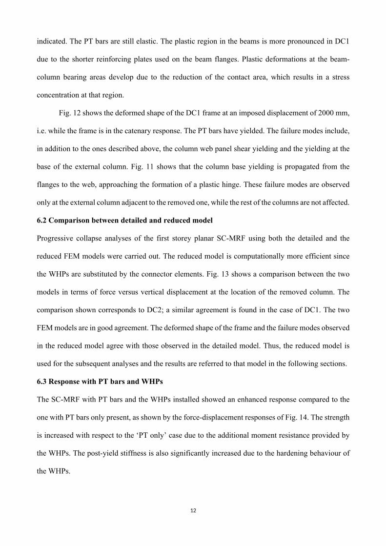
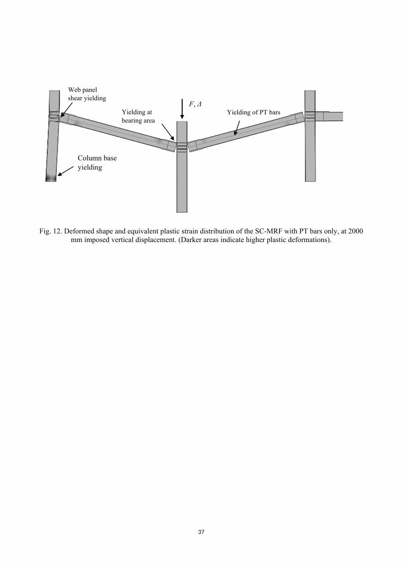
Fig. 12 shows the deformed shape of the DC1 frame at an imposed displacement of 2000 mm,
i.e. while the frame is in the catenary response. The PT bars have yielded. The failure modes include,
in addition to the ones described above, the column web panel shear yielding and the yielding at the
base of the external column. Fig. 11 shows that the column base yielding is propagated from the
flanges to the web, approaching the formation of a plastic hinge. These failure modes are observed
only at the external column adjacent to the removed one, while the rest of the columns are not affected.
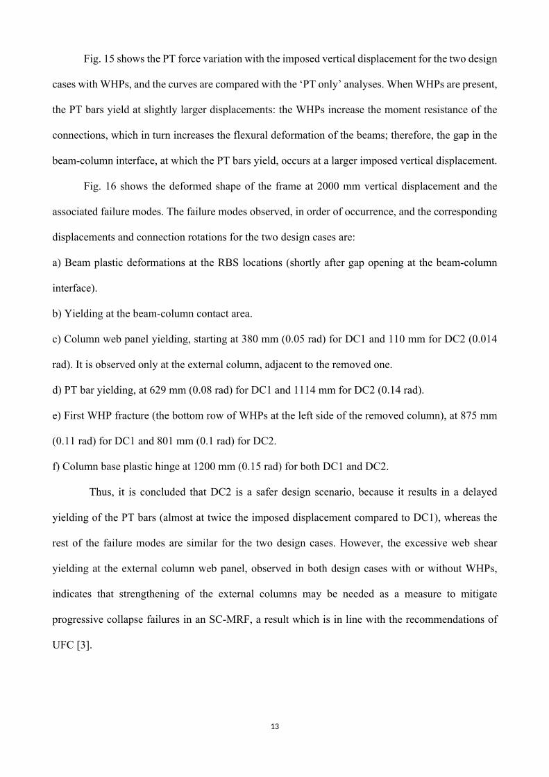
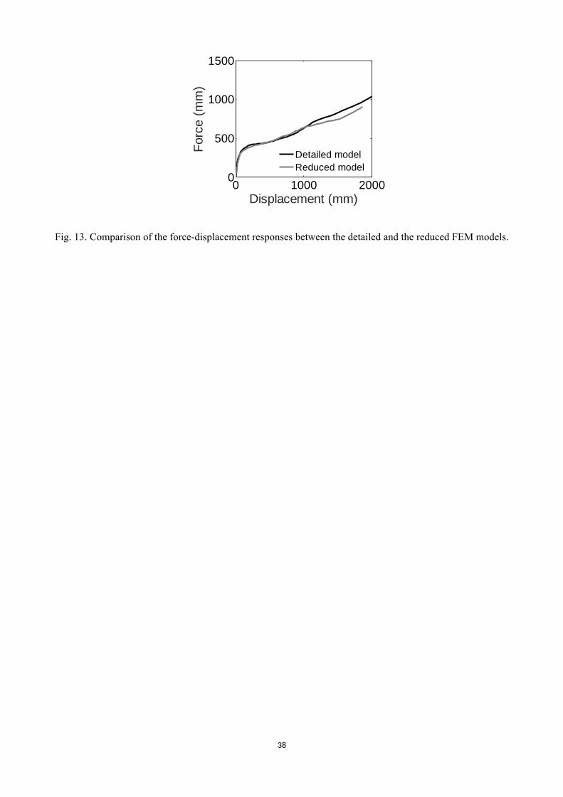
6.2 Comparison between detailed and reduced model
Progressive collapse analyses of the first storey planar SC-MRF using both the detailed and the
reduced FEM models were carried out. The reduced model is computationally more efficient since
the WHPs are substituted by the connector elements. Fig. 13 shows a comparison between the two
models in terms of force versus vertical displacement at the location of the removed column. The
comparison shown corresponds to DC2; a similar agreement is found in the case of DC1. The two
FEM models are in good agreement. The deformed shape of the frame and the failure modes observed
in the reduced model agree with those observed in the detailed model. Thus, the reduced model is
used for the subsequent analyses and the results are referred to that model in the following sections.
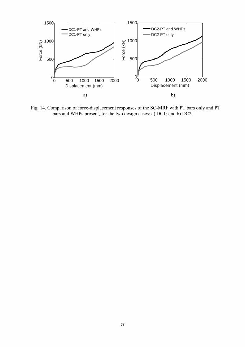
6.3 Response with PT bars and WHPs
The SC-MRF with PT bars and the WHPs installed showed an enhanced response compared to the
one with PT bars only present, as shown by the force-displacement responses of Fig. 14. The strength
is increased with respect to the ‘PT only’ case due to the additional moment resistance provided by
the WHPs. The post-yield stiffness is also significantly increased due to the hardening behaviour of
the WHPs.
13
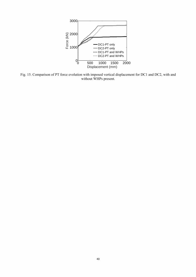
Fig. 15 shows the PT force variation with the imposed vertical displacement for the two design
cases with WHPs, and the curves are compared with the ‘PT only’ analyses. When WHPs are present,
the PT bars yield at slightly larger displacements: the WHPs increase the moment resistance of the
connections, which in turn increases the flexural deformation of the beams; therefore, the gap in the
beam-column interface, at which the PT bars yield, occurs at a larger imposed vertical displacement.
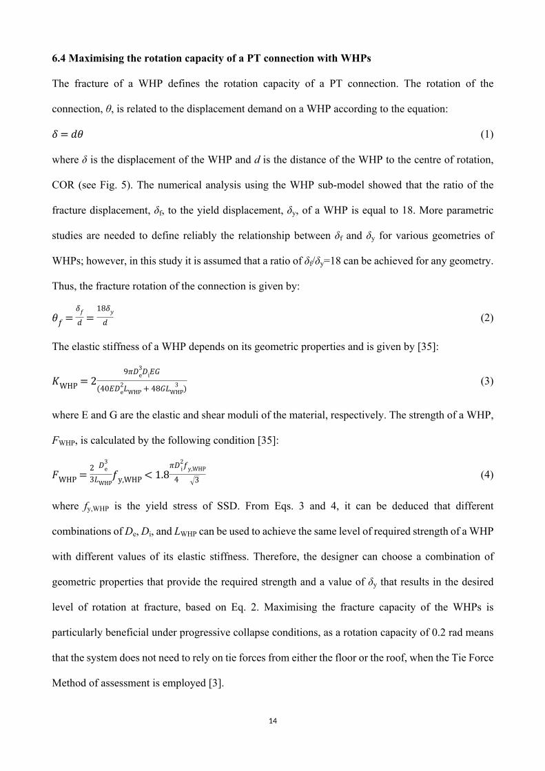
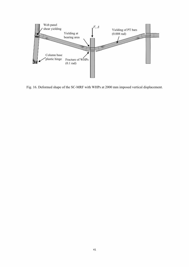
Fig. 16 shows the deformed shape of the frame at 2000 mm vertical displacement and the
associated failure modes. The failure modes observed, in order of occurrence, and the corresponding
displacements and connection rotations for the two design cases are:
a) Beam plastic deformations at the RBS locations (shortly after gap opening at the beam-column
interface).
b) Yielding at the beam-column contact area.
c) Column web panel yielding, starting at 380 mm (0.05 rad) for DC1 and 110 mm for DC2 (0.014
rad). It is observed only at the external column, adjacent to the removed one.
d) PT bar yielding, at 629 mm (0.08 rad) for DC1 and 1114 mm for DC2 (0.14 rad).
e) First WHP fracture (the bottom row of WHPs at the left side of the removed column), at 875 mm
(0.11 rad) for DC1 and 801 mm (0.1 rad) for DC2.
f) Column base plastic hinge at 1200 mm (0.15 rad) for both DC1 and DC2.
Thus, it is concluded that DC2 is a safer design scenario, because it results in a delayed
yielding of the PT bars (almost at twice the imposed displacement compared to DC1), whereas the
rest of the failure modes are similar for the two design cases. However, the excessive web shear
yielding at the external column web panel, observed in both design cases with or without WHPs,
indicates that strengthening of the external columns may be needed as a measure to mitigate
progressive collapse failures in an SC-MRF, a result which is in line with the recommendations of
UFC [3].
14
6.4 Maximising the rotation capacity of a PT connection with WHPs
The fracture of a WHP defines the rotation capacity of a PT connection. The rotation of the
connection, θ, is related to the displacement demand on a WHP according to the equation:
(1)𝛿 = 𝑑𝜃
where δ is the displacement of the WHP and d is the distance of the WHP to the centre of rotation,
COR (see Fig. 5). The numerical analysis using the WHP sub-model showed that the ratio of the
fracture displacement, δf, to the yield displacement, δy, of a WHP is equal to 18. More parametric
studies are needed to define reliably the relationship between δf and δy for various geometries of
WHPs; however, in this study it is assumed that a ratio of δf/δy=18 can be achieved for any geometry.
Thus, the fracture rotation of the connection is given by:
(2)𝜃𝑓 =𝛿𝑓
𝑑 =18𝛿𝑦
𝑑
The elastic stiffness of a WHP depends on its geometric properties and is given by [35]:
(3)𝐾WHP = 29𝜋𝐷3
e𝐷i𝐸𝐺
(40𝐸𝐷2e𝐿WHP + 48𝐺𝐿 3
WHP)
where E and G are the elastic and shear moduli of the material, respectively. The strength of a WHP,
FWHP, is calculated by the following condition [35]:
(4)𝐹WHP =23
𝐷3e
𝐿WHP𝑓y,WHP < 1.8
𝜋𝐷2i
4
𝑓y,WHP
3
where fy,WHP is the yield stress of SSD. From Eqs. 3 and 4, it can be deduced that different
combinations of De, Di, and LWHP can be used to achieve the same level of required strength of a WHP
with different values of its elastic stiffness. Therefore, the designer can choose a combination of
geometric properties that provide the required strength and a value of δy that results in the desired
level of rotation at fracture, based on Eq. 2. Maximising the fracture capacity of the WHPs is
particularly beneficial under progressive collapse conditions, as a rotation capacity of 0.2 rad means
that the system does not need to rely on tie forces from either the floor or the roof, when the Tie Force
Method of assessment is employed [3].
15
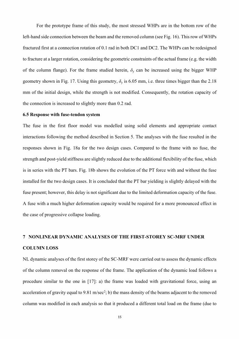
For the prototype frame of this study, the most stressed WHPs are in the bottom row of the
left-hand side connection between the beam and the removed column (see Fig. 16). This row of WHPs
fractured first at a connection rotation of 0.1 rad in both DC1 and DC2. The WHPs can be redesigned
to fracture at a larger rotation, considering the geometric constraints of the actual frame (e.g. the width
of the column flange). For the frame studied herein, δy can be increased using the bigger WHP
geometry shown in Fig. 17. Using this geometry, δy is 6.05 mm, i.e. three times bigger than the 2.18
mm of the initial design, while the strength is not modified. Consequently, the rotation capacity of
the connection is increased to slightly more than 0.2 rad.
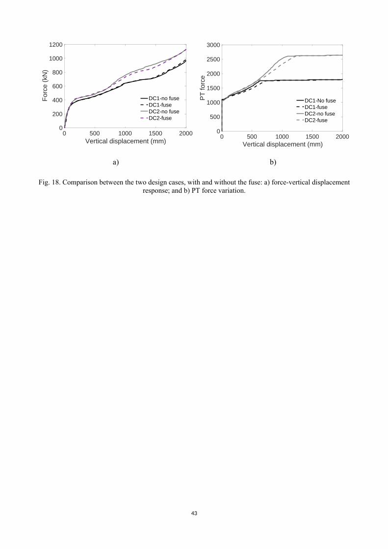
6.5 Response with fuse-tendon system
The fuse in the first floor model was modelled using solid elements and appropriate contact
interactions following the method described in Section 5. The analyses with the fuse resulted in the
responses shown in Fig. 18a for the two design cases. Compared to the frame with no fuse, the
strength and post-yield stiffness are slightly reduced due to the additional flexibility of the fuse, which
is in series with the PT bars. Fig. 18b shows the evolution of the PT force with and without the fuse
installed for the two design cases. It is concluded that the PT bar yielding is slightly delayed with the
fuse present; however, this delay is not significant due to the limited deformation capacity of the fuse.
A fuse with a much higher deformation capacity would be required for a more pronounced effect in
the case of progressive collapse loading.
7 NONLINEAR DYNAMIC ANALYSES OF THE FIRST-STOREY SC-MRF UNDER
COLUMN LOSS
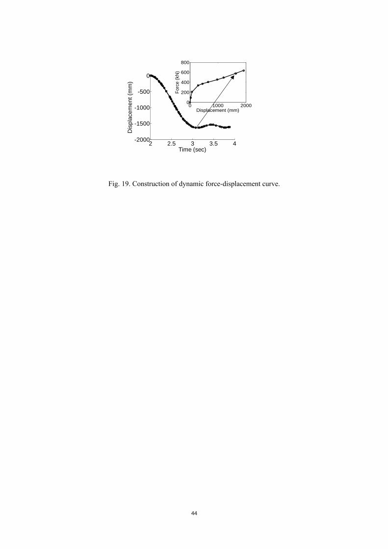
NL dynamic analyses of the first storey of the SC-MRF were carried out to assess the dynamic effects
of the column removal on the response of the frame. The application of the dynamic load follows a
procedure similar to the one in [17]: a) the frame was loaded with gravitational force, using an
acceleration of gravity equal to 9.81 m/sec2; b) the mass density of the beams adjacent to the removed
column was modified in each analysis so that it produced a different total load on the frame (due to
16
the self-weight of the beams); c) the penultimate column was instantaneously ‘removed’ (i.e. the
supports were released) and left to be pushed down by the gravitational load; d) the analysis was
continued until the oscillation of the frame has died out, and the maximum vertical displacement was
recorded; and e) the pairs of total load and maximum vertical displacement corresponding to each
analysis were used to construct the dynamic force-displacement curve of the SC-MRF. This
procedure is schematically shown in Fig. 19.
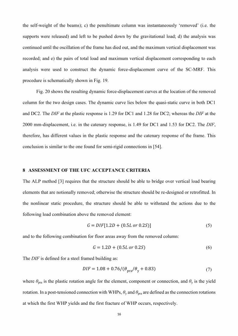
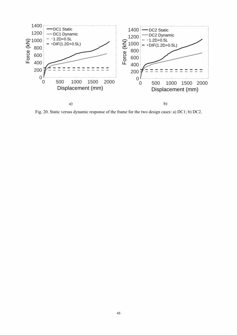
Fig. 20 shows the resulting dynamic force-displacement curves at the location of the removed
column for the two design cases. The dynamic curve lies below the quasi-static curve in both DC1
and DC2. The DIF at the plastic response is 1.29 for DC1 and 1.28 for DC2; whereas the DIF at the
2000 mm-displacement, i.e. in the catenary response, is 1.49 for DC1 and 1.53 for DC2. The DIF,
therefore, has different values in the plastic response and the catenary response of the frame. This
conclusion is similar to the one found for semi-rigid connections in [54].
8 ASSESSMENT OF THE UFC ACCEPTANCE CRITERIA
The ALP method [3] requires that the structure should be able to bridge over vertical load bearing
elements that are notionally removed; otherwise the structure should be re-designed or retrofitted. In
the nonlinear static procedure, the structure should be able to withstand the actions due to the
following load combination above the removed element:
𝐺 = 𝐷𝐼𝐹[1.2𝐷 + (0.5𝐿 𝑜𝑟 0.2𝑆)] (5)
and to the following combination for floor areas away from the removed column:
𝐺 = 1.2𝐷 + (0.5𝐿 𝑜𝑟 0.2𝑆) (6)
The DIF is defined for a steel framed building as:
𝐷𝐼𝐹 = 1.08 + 0.76/(𝜃pra/𝜃y + 0.83) (7)
where θpra is the plastic rotation angle for the element, component or connection, and θy is the yield
rotation. In a post-tensioned connection with WHPs, θy and θpra are defined as the connection rotations
at which the first WHP yields and the first fracture of WHP occurs, respectively.
17
From Eq. (1) the connection rotation is directly related to the displacement of the WHP. Thus,
δf/δy = θpra/θy = 18. Using this ratio in Eq. (7), the DIF is 1.12 for the SC-MRF. Comparing this value
with the DIF found in the dynamic analyses, i.e. approximately 1.3 in the plastic response and 1.5 in
the catenary response, it is concluded that the DIF calculated using Eq. (7) is a non-conservative value
to account for the dynamic effects of the progressive collapse in a SC-MRF. More studies on different
geometries of SC-MRFs are needed to safely generalise this conclusion.
The load combinations obtained using Eqs. (5) and (6) using DIF = 1.3 are plotted in Fig. 20.
From the graphs, it is evident that the SC-MRF is able to withstand the required load combination
after a sudden column removal while still in the elastic range.
9 PROGRESSIVE COLLAPSE SIMULATION OF THE FIVE-STOREY SC-MRF
Progressive collapse simulations of the five-storey planar SC-MRF using the reduced FEM model
were carried out. Although the five-storey frame analyses are considerably more demanding in terms
of computational time, they serve to study possible differences in the overall response as compared
to the first storey frame simulations. A quasi-static analysis using the implicit dynamic solver was
performed for each design case. The fuses were not modelled, as it is not expected that their
contribution will be significantly different than that shown in Fig. 18. The same modelling
assumptions as in the first storey frame simulations were made. The WHPs were redesigned to
provide a rotation capacity of the beam-column connections at fracture greater than 0.2 rad, using the
methodology described in Section 6.3. Table 2 provides the geometric details of the optimised WHPs,
their yield displacement, and the connection rotation, θf, at which the fracture of the most distant from
the COR WHP occurs.
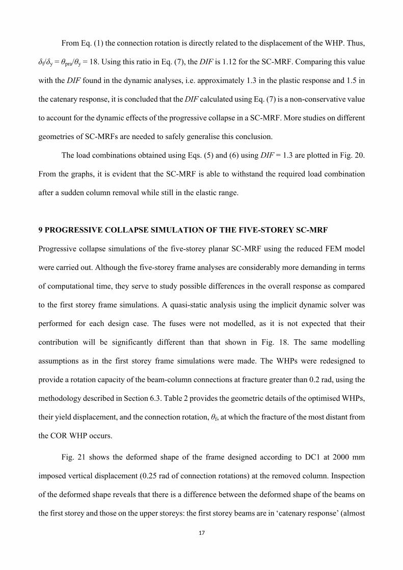
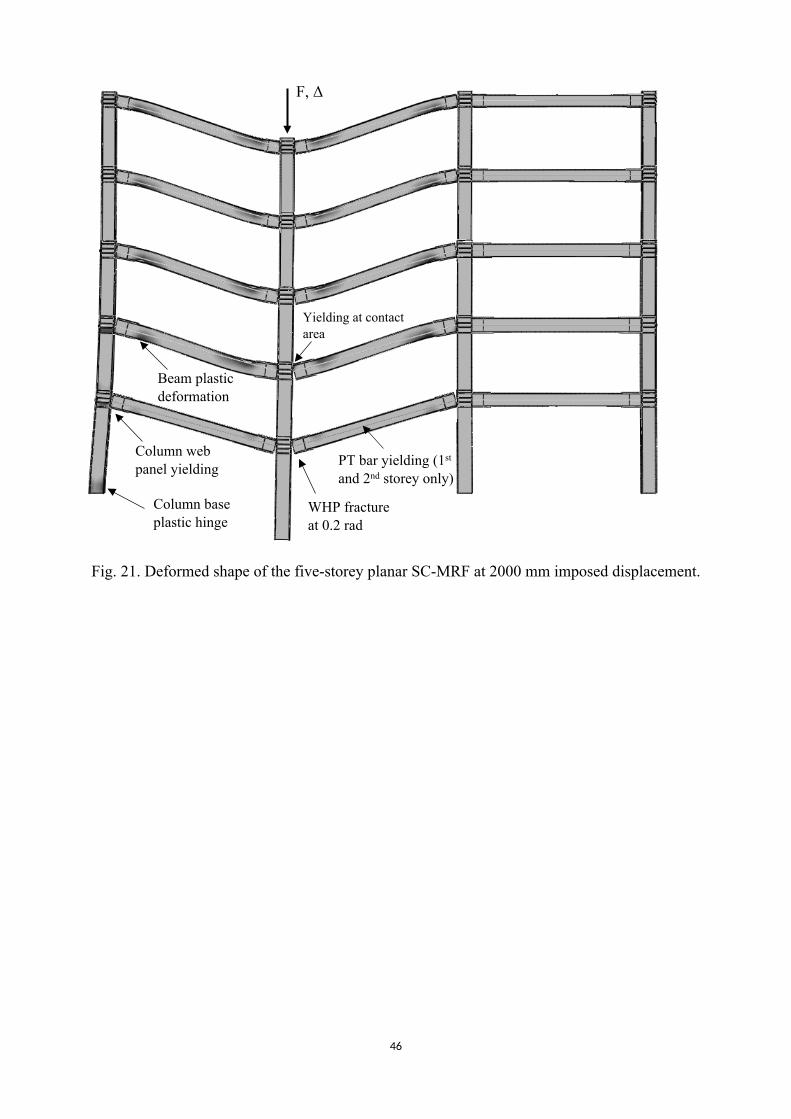
Fig. 21 shows the deformed shape of the frame designed according to DC1 at 2000 mm
imposed vertical displacement (0.25 rad of connection rotations) at the removed column. Inspection
of the deformed shape reveals that there is a difference between the deformed shape of the beams on
the first storey and those on the upper storeys: the first storey beams are in ‘catenary response’ (almost
18
straight deformed shape), whereas the beams on the upper stories are in ‘plastic response’ with much
more pronounced plastic deformations in the RBS locations. This behaviour is observed for both DC1
and DC2 and it can be explained by the significant shear distortion of the web panel and the plastic
deformations at the base of the external column on the first storey (foremost left column in Fig. 21).
This column leans towards the upper storeys creating a restraining effect that does not allow the
development of catenary action in the beams of the upper storeys.
The failure modes are indicated in Fig. 21, and they include: a) beam yielding at the RBS
locations, which is less noticeable on the first storey, but more extended on the upper storeys; b)
external column web panel shear yielding, which occurred only at the first and second storeys; c)
yielding at the beam-column contact area as the gaps open; d) plastic hinge formation at the base of
the external column adjacent to the removed column; e) PT bar yielding in the first and second
storeys; and f) WHP fracture at 0.2 rad of connection rotation in the first storey, as designed.
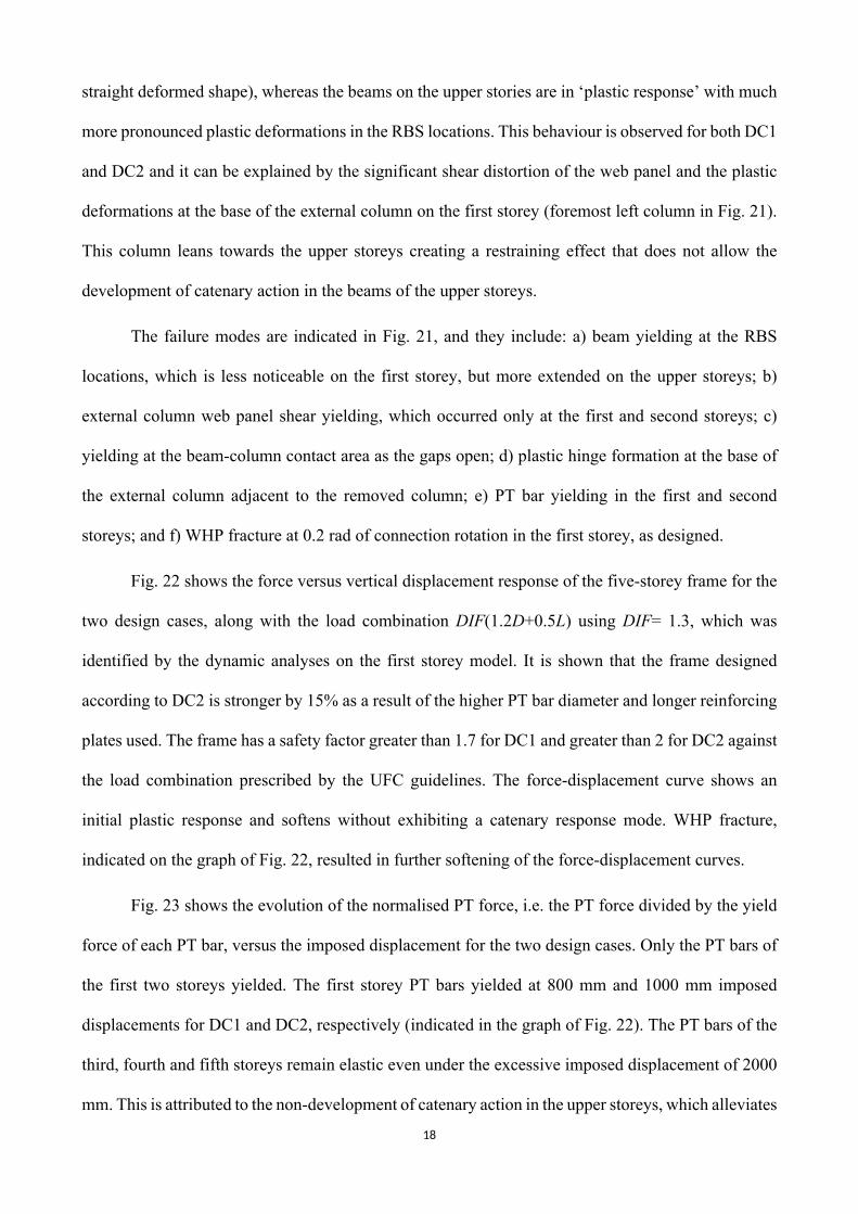
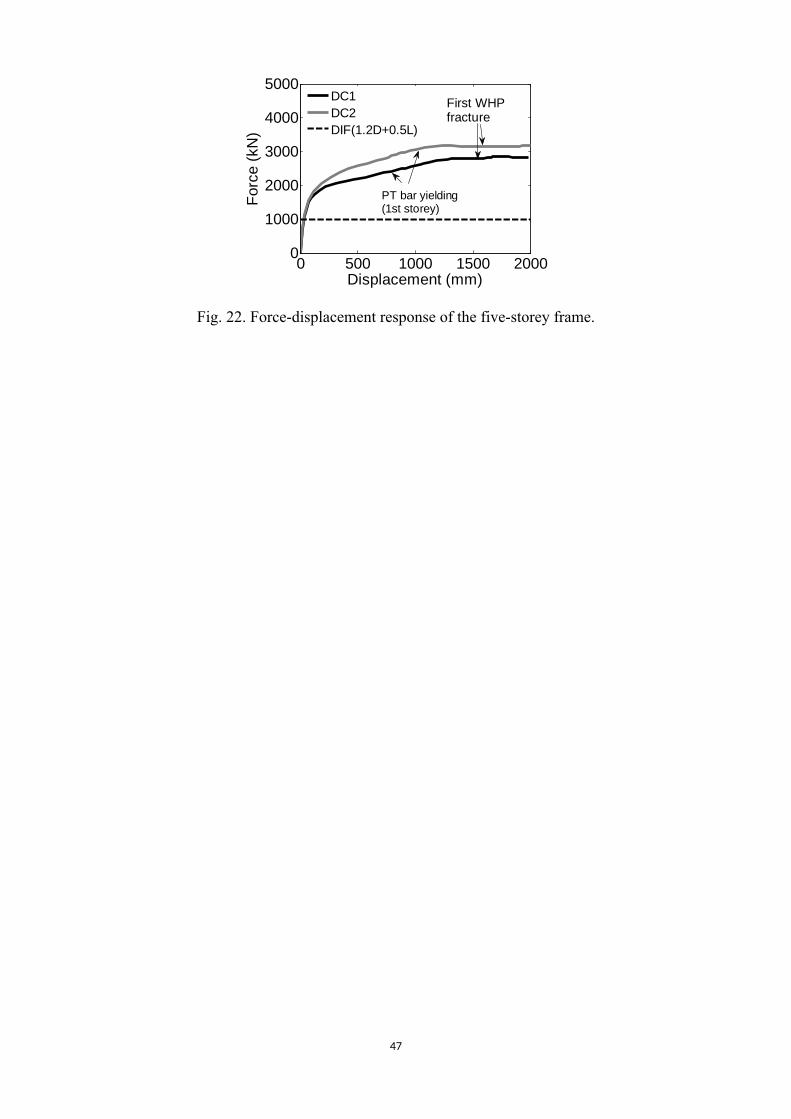
Fig. 22 shows the force versus vertical displacement response of the five-storey frame for the
two design cases, along with the load combination DIF(1.2D+0.5L) using DIF= 1.3, which was
identified by the dynamic analyses on the first storey model. It is shown that the frame designed
according to DC2 is stronger by 15% as a result of the higher PT bar diameter and longer reinforcing
plates used. The frame has a safety factor greater than 1.7 for DC1 and greater than 2 for DC2 against
the load combination prescribed by the UFC guidelines. The force-displacement curve shows an
initial plastic response and softens without exhibiting a catenary response mode. WHP fracture,
indicated on the graph of Fig. 22, resulted in further softening of the force-displacement curves.
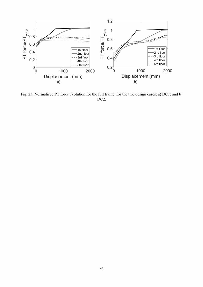
Fig. 23 shows the evolution of the normalised PT force, i.e. the PT force divided by the yield
force of each PT bar, versus the imposed displacement for the two design cases. Only the PT bars of
the first two storeys yielded. The first storey PT bars yielded at 800 mm and 1000 mm imposed
displacements for DC1 and DC2, respectively (indicated in the graph of Fig. 22). The PT bars of the
third, fourth and fifth storeys remain elastic even under the excessive imposed displacement of 2000
mm. This is attributed to the non-development of catenary action in the upper storeys, which alleviates
19
the demands for elongation in the PT bars. A slight relaxation in the PT bar forces of the upper storeys
is observed in Fig. 23, as a result of the plastic bending of the beams under the restraining effect of
the external column which causes a slight decrease in the length of the PT bars. It is concluded that
the first storey is the most critical based on the likelihood of WHP and PT bar fracture, whereas DC2
provides a higher safety margin against PT bar yielding.
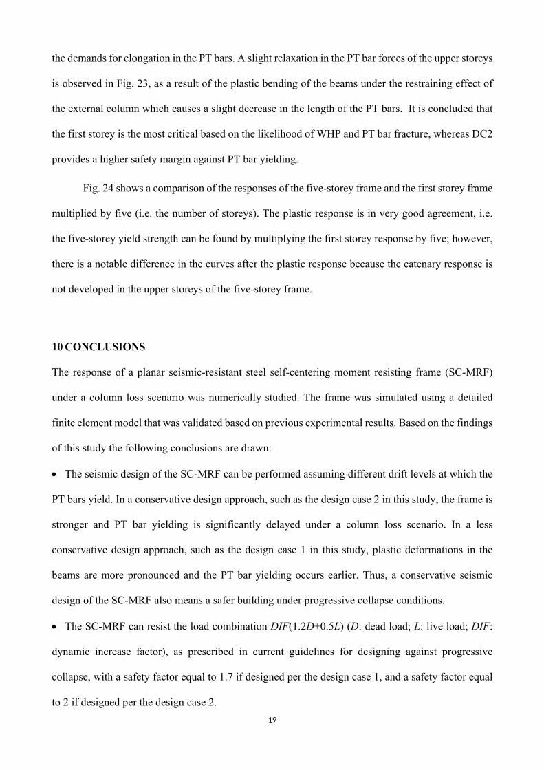
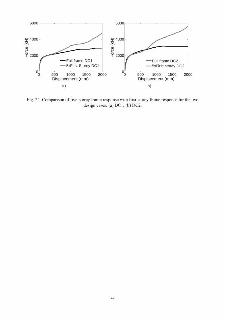
Fig. 24 shows a comparison of the responses of the five-storey frame and the first storey frame
multiplied by five (i.e. the number of storeys). The plastic response is in very good agreement, i.e.
the five-storey yield strength can be found by multiplying the first storey response by five; however,
there is a notable difference in the curves after the plastic response because the catenary response is
not developed in the upper storeys of the five-storey frame.
10 CONCLUSIONS
The response of a planar seismic-resistant steel self-centering moment resisting frame (SC-MRF)
under a column loss scenario was numerically studied. The frame was simulated using a detailed
finite element model that was validated based on previous experimental results. Based on the findings
of this study the following conclusions are drawn:
The seismic design of the SC-MRF can be performed assuming different drift levels at which the
PT bars yield. In a conservative design approach, such as the design case 2 in this study, the frame is
stronger and PT bar yielding is significantly delayed under a column loss scenario. In a less
conservative design approach, such as the design case 1 in this study, plastic deformations in the
beams are more pronounced and the PT bar yielding occurs earlier. Thus, a conservative seismic
design of the SC-MRF also means a safer building under progressive collapse conditions.
The SC-MRF can resist the load combination DIF(1.2D+0.5L) (D: dead load; L: live load; DIF:
dynamic increase factor), as prescribed in current guidelines for designing against progressive
collapse, with a safety factor equal to 1.7 if designed per the design case 1, and a safety factor equal
to 2 if designed per the design case 2.
20
The SC-MRF with PT bars only installed (without WHPs) can still resist the required load
combination with an acceptable safety margin only when the frame is designed per the design case 2.
The external column, adjacent to the one ‘removed’, is susceptible to excessive web panel yielding
and plastic hinge formation at the base. Therefore, strengthening of the external columns is
recommended if progressive collapse is a potential threat.
The use of a steel ‘fuse’ in series with the PT bars can delay the PT bar yielding; however, for
practical fuse lengths this delay is insignificant.
The WHPs made of duplex stainless steel are very ductile in monotonic loading and their use
results in a robust frame. The geometric properties of the WHPs can be adjusted so that they yield at
connection rotations greater than 0.2 rad, meaning that the frame needs not rely on tie forces from the
floor or the roof.
The nonlinear dynamic analyses showed that the dynamic increase factor for the specific SC-MRF
is 1.3 at the plastic response and 1.5 at the catenary response phase. This value is higher than the one
calculated according to the formula prescribed in the UFC guidelines, which is equal to 1.12.
The simulations using the five-storey planar SC-MRF showed that the first storey is the most
critical. The deformation demands on the web panel of the external column are much greater on the
first storey than on the upper storeys, resulting in a ‘catenary response’ of the beams of the first storey
and ‘flexural response’ of the beams of the upper storeys. This results in PT bar yielding only at the
first and second storeys, whereas the resistance at the upper storeys rely on the plastic resistance of
the beams and the WHPs.
This study provides initial data on the progressive collapse response of a realistic planar SC-
MRF equipped with stainless-steel energy-dissipating devices, under the following limitations: a) it
does not account the 3-dimensional effects of the gravity frame; b) it concerns the specific geometry
of the prototype SC-MRF used in this study; and c) it concerns PT connections with the specific
structural details for preventing beam buckling outlined in Section 2.
21
REFERENCES
[1] British Standards Institution, “BS EN 1991-1-7:2006+A1:2014 Eurocode 1 - Actions on structures - Part 1-7: General actions - Accidental actions.” 2006.
[2] GSA, “Alternate Path Analysis & Design Guidelines for Progressive Collapse Resistance,” 2013.
[3] DoD, UNIFIED FACILITIES CRITERIA ( UFC ) DESIGN OF BUILDINGS TO RESIST PROGRESSIVE COLLAPSE. 2009.
[4] L. Guo, S. Gao, F. Fu, and Y. Wang, “Experimental study and numerical analysis of progressive collapse resistance of composite frames,” J. Constr. Steel Res., vol. 89, pp. 236–251, 2013.
[5] J.-F. Demonceau and J.-P. Jaspart, “Experimental test simulating a column loss in a composite frame,” Adv. Steel Constr., vol. 6, no. Number 3, Sep. 2010.
[6] H. Zolghadr Jahromi, B. Izzuddin, D. Nethercot, S. Donahue, M. Hadjioannou, E. Williamson, M. Engelhardt, D. Stevens, K. Marchand, and M. Waggoner, “Robustness Assessment of Building Structures under Explosion,” Buildings, vol. 2, no. 4, pp. 497–518, 2012.
[7] E. S. Johnson, A. M. Asce, J. E. Meissner, A. M. Asce, L. A. Fahnestock, and M. Asce, “Experimental Behavior of a Half-Scale Steel Concrete Composite Floor System Subjected To Column Removal Scenarios,” J. Struct. Eng., vol. 142, no. 2, pp. 1–12, 2016.
[8] F. Dinu, I. Marginean, D. Dubina, and I. Petran, “Experimental testing and numerical analysis of 3D steel frame system under column loss,” Eng. Struct., vol. 113, pp. 59–70, 2016.
[9] B. I. Song and H. Sezen, “Experimental and analytical progressive collapse assessment of a steel frame building,” Eng. Struct., vol. 56, pp. 664–672, 2013.
[10] B. I. Song, K. A. Giriunas, and H. Sezen, “Progressive collapse testing and analysis of a steel frame building,” J. Constr. Steel Res., vol. 94, pp. 76–83, Mar. 2014.
[11] B. Yang and K. H. Tan, “Experimental tests of different types of bolted steel beam–column joints under a central-column-removal scenario,” Eng. Struct., vol. 54, no. 2, pp. 112–130, Sep. 2013.
[12] B. Yang and K. H. Tan, “Behavior of Composite Beam-Column Joints in a Middle-Column-Removal Scenario: Experimental Tests,” J. Struct. Eng., vol. 140, no. 2, p. 04013045, Feb. 2014.
[13] W. Wang, C. Fang, X. Qin, Y. Chen, and L. Li, “Performance of practical beam-to-SHS column connections against progressive collapse,” Eng. Struct., vol. 106, pp. 332–347, Jan. 2016.
[14] F. Sadek, S. El-Tawil, and H. S. Lew, “Robustness of Composite Floor Systems with Shear Connections: Modeling, Simulation, and Evaluation,” J. Struct. Eng., vol. 134, no. 11, pp. 1717–1725, Nov. 2008.
[15] Y. Alashker, D. Ph, S. El-tawil, and F. Sadek, “Progressive Collapse Resistance of Steel-Concrete Composite Floors,” vol. 136, no. 10, pp. 1187–1196, 2010.
[16] Y. Alashker and S. El-Tawil, “A design-oriented model for the collapse resistance of composite floors subjected to column loss,” J. Constr. Steel Res., vol. 67, no. 1, pp. 84–92, Jan. 2011.
[17] J. A. Main, “Composite Floor Systems under Column Loss: Collapse Resistance and Tie Force Requirements,” J. Struct. Eng., p. A4014003, Feb. 2014.
[18] F. Fu, “Progressive collapse analysis of high-rise building with 3-D finite element modeling method,” J. Constr. Steel Res., vol. 65, no. 6, pp. 1269–1278, Jun. 2009.
[19] F. Fu, “3-D nonlinear dynamic progressive collapse analysis of multi-storey steel composite frame buildings — Parametric study,” Eng. Struct., vol. 32, no. 12, pp. 3974–3980, Dec. 2010.
[20] H. Li and S. El-Tawil, “Three-Dimensional Effects and Collapse Resistance Mechanisms in Steel Frame Buildings,” J. Struct. Eng., p. 130312224713002, Mar. 2013.
[21] F. X. Flores, F. a. Charney, and D. Lopez-Garcia, “Influence of the gravity framing system on the collapse performance of special steel moment frames,” J. Constr. Steel Res., vol. 101,
22
pp. 351–362, Oct. 2014.[22] K. Khandelwal and S. El-Tawil, “Collapse Behavior of Steel Special Moment Resisting
Frame Connections,” J. Struct. Eng., vol. 133, no. 5, pp. 646–655, May 2007.[23] G. Xu and B. R. Ellingwood, “Disproportionate collapse performance of partially restrained
steel frames with bolted T-stub connections,” Eng. Struct., vol. 33, no. 1, pp. 32–43, Jan. 2011.
[24] F. Sadek, J. A. Main, H. S. Lew, and S. El-Tawil, “Performance of Steel Moment Connections under a Column Removal Scenario. II: Analysis,” J. Struct. Eng., vol. 139, no. 1, pp. 108–119, Jan. 2013.
[25] B. A. Izzuddin, A. G. Vlassis, A. Y. Elghazouli, and D. A. Nethercot, “Progressive collapse of multi-storey buildings due to sudden column loss — Part I: Simplified assessment framework,” Eng. Struct., vol. 30, no. 5, pp. 1308–1318, May 2008.
[26] H. Zolghadr Jahromi, A. G. Vlassis, and B. A. Izzuddin, “Modelling approaches for robustness assessment of multi-storey steel-composite buildings,” Eng. Struct., vol. 51, pp. 278–294, Jun. 2013.
[27] S. Gerasimidis, “Analytical assessment of steel frames progressive collapse vulnerability to corner column loss,” J. Constr. Steel Res., vol. 95, pp. 1–9, Apr. 2014.
[28] A. G. Vlassis, B. A. Izzuddin, A. Y. Elghazouli, and D. A. Nethercot, “Progressive collapse of multi-storey buildings due to sudden column loss—Part II: Application,” Eng. Struct., vol. 30, no. 5, pp. 1424–1438, May 2008.
[29] J. M. Ricles, R. Sause, M. M. Garlock, and C. Zhao, “Posttensioned Seismic-Resistant Connections for Steel Frames,” J. Struct. Eng., vol. 127, no. 2, pp. 113–121, Feb. 2001.
[30] J. M. Ricles, R. Sause, S. W. Peng, and L. W. Lu, “Experimental Evaluation of Earthquake Resistant Posttensioned Steel Connections,” J. Struct. Eng., vol. 128, no. 7, pp. 850–859, 2002.
[31] C. Christopoulos, A. Filiatrault, C. Uang, and B. Folz, “Posttensioned Energy Dissipating Connections for Moment-Resisting Steel Frames,” J. Struct. Eng., vol. 128, no. 9, 2003.
[32] M. M. Garlock, J. M. Ricles, R. Sause, and M. Asce, “Experimental Studies of Full-Scale Posttensioned Steel Connections,” J. Struct. Eng., vol. 131, no. 3, 2005.
[33] C.-C. Chou, J.-H. Chen, Y.-C. Chen, and K.-C. Tsai, “Evaluating performance of post-tensioned steel connections with strands and reduced flange plates,” Earthq. Eng. Struct. Dyn., vol. 35, no. 9, pp. 1167–1185, Jul. 2006.
[34] C.-C. Chou and Y.-J. Lai, “Post-tensioned self-centering moment connections with beam bottom flange energy dissipators,” J. Constr. Steel Res., vol. 65, no. 10–11, pp. 1931–1941, Oct. 2009.
[35] G. Vasdravellis, T. L. Karavasilis, and B. Uy, “Large-Scale Experimental Validation of Steel Posttensioned Connections with Web Hourglass Pins,” J. Struct. Eng., vol. 139, no. 6, pp. 1033–1042, Jun. 2013.
[36] P. Rojas, J. M. Ricles, and R. Sause, “Seismic Performance of Post-tensioned Steel Moment Resisting Frames With Friction Devices,” J. Struct. Eng., vol. 131, no. 4, 2005.
[37] K. Tsai, C. Chou, and C. Lin, “Seismic self-centering steel beam-to-column moment connections using bolted friction devices,” Earthq. Eng. Struct. Dyn., vol. 37, pp. 627–645, 2008.
[38] H. Kim and C. Christopoulos, “Friction Damped Posttensioned Self-Centering Steel Moment-Resisting Frames,” J. Struct. Eng., vol. 134, no. 11, pp. 1768–1779, 2008.
[39] J. Iyama, C.-Y. Seo, J. M. Ricles, and R. Sause, “Self-centering MRFs with bottom flange friction devices under earthquake loading,” J. Constr. Steel Res., vol. 65, no. 2, pp. 314–325, Feb. 2009.
[40] M. Wolski, J. M. Ricles, and R. Sause, “Experimental Study of a Self-Centering Beam–Column Connection with Bottom Flange Friction Device,” J. Struct. Eng., vol. 135, no. 5, pp. 479–488, May 2009.
[41] Tsitos, “Experimental study of progressive collapse os conventional and PT steel frames,” pp. 1–10, Apr. 2010.
[42] A. Pirmoz and M. M. Liu, “Finite element modeling and capacity analysis of post-tensioned steel frames against progressive collapse,” Eng. Struct., vol. 126, pp. 446–456, 2016.
23
[43] G. Vasdravellis, T. L. Karavasilis, and B. Uy, “Design rules, experimental evaluation, and fracture models for high-strength and stainless-steel hourglass shape energy dissipation devices,” J. Struct. Eng. (United States), vol. 140, no. 11, 2014.
[44] G. Vasdravellis, T. L. Karavasilis, and B. Uy, “Finite element models and cyclic behavior of self-centering steel post-tensioned connections with web hourglass pins,” Eng. Struct., vol. 52, pp. 1–16, 2013.
[45] A. S. Tzimas, A. I. Dimopoulos, and T. L. Karavasilis, “EC8-based seismic design and assessment of self-centering post-tensioned steel frames with viscous dampers,” J. Constr. Steel Res., vol. 105, pp. 60–73, Feb. 2015.
[46] Y.-C. Lin, R. Sause, and J. Ricles, “Seismic Performance of a Large-Scale Steel Self-Centering Moment-Resisting Frame: MCE Hybrid Simulations and Quasi-Static Pushover Tests,” J. Struct. Eng., vol. 139, no. 7, pp. 1227–1236, Jul. 2013.
[47] C.-C. Chou and J.-H. Chen, “Development of floor slab for steel post-tensioned self-centering moment frames,” J. Constr. Steel Res., vol. 67, no. 10, pp. 1621–1635, Oct. 2011.
[48] H. Kim and C. Christopoulos, “Seismic design procedure and seismic response of post-tensioned self-centering steel frames,” Earthq. Eng. Struct. Dyn., vol. 38, pp. 355–376, 2009.
[49] H. Kim and C. Christopoulos, “Numerical models and ductile ultimate deformation response of post-tensioned self-centering moment connections,” Earthq. Eng. Struct. Dyn., vol. 38, pp. 1–21, 2009.
[50] A. I. Dimopoulos, T. L. Karavasilis, G. Vasdravellis, and B. Uy, “Seismic design, modelling and assessment of self-centering steel frames using post-tensioned connections with web hourglass shape pins,” Bull. Earthq. Eng., vol. 11, no. 5, pp. 1797–1816, 2013.
[51] ABAQUS, “Abaqus Analysis User’s Manual.” 2011.[52] A. M. Kanvinde, A. M. Asce, G. G. Deierlein, and F. Asce, “Void Growth Model and Stress
Modified Critical Strain Model to Predict Ductile Fracture in Structural Steels,” no. December, pp. 1907–1918, 2006.
[53] G. Vasdravellis, B. Uy, E. L. Tan, and B. Kirkland, “Behaviour and design of composite beams subjected to sagging bending and compression,” J. Constr. Steel Res., vol. 79, pp. 34–47, 2012.
[54] J. Kim and T. Kim, “Assessment of progressive collapse-resisting capacity of steel moment frames,” J. Constr. Steel Res., vol. 65, no. 1, pp. 169–179, Jan. 2009.
24
Table 1: Properties of the prototype SC-MRF
Sections PT bars WHPs (SSD) Reinforcingplates Fuse
Storey Beam Column dPT T0 De Di LWHP Lrp Arp Afuse
Design Case 1 (DC1)1 IPE 550 HEB 650 36 1087 34 23 70 818 5243 41022 IPE 600 HEB 650 40 1256 37 26 70 935 6476 51463 IPE 550 HEB 650 36 1087 35 23 70 828 5306 42574 IPE 500 HEB 600 32 941 33 21 70 717 4224 33845 IPE 500 HEB 600 32 941 31 20 70 622 3663 3232
Design Case 2 (DC2)1 IPE 550 HEB 650 43 1087 34 23 70 1258 6720 68702 IPE 600 HEB 650 50 1256 37 26 70 1461 8580 91503 IPE 550 HEB 650 43 1087 35 23 70 1311 6720 72104 IPE 500 HEB 600 37 941 33 21 70 1073 5200 54905 IPE 500 HEB 600 35 941 31 20 70 724 4200 5060Note: dPT: diameter of a PT bar; T0: initial PT force; Lrp: required length of reinforcing plates; Arp: required
area of reinforcing plates; Afuse: effective area of fuse (units in kN, mm)

25
Table 2: Geometric properties of optimised WHPs in the five-storey frame simulations
Storey De Di LWHP δy θf1 41 22 120 6.05 0.242 44 25 120 5.8 0.213 42 23 120 6.1 0.244 39 21 120 5 0.225 37 19 120 5 0.22
Note: Units in mm, rad
26
Gravityframe
4 m
3x8 m
4x3.
2 m
SC-MRF (modelled frame)
SC-MRF5x
5m
3x8m
Brac
ed fr
ame
Brac
ed fr
ame
XY
ZX
Z
Y
4 m
3x8 m
4x3.
2 m
XZ
Y(a) (b)
Fig. 1. a) Plan view of the prototype building; b) elevation of an X-direction SC-MRF.
27
Supportingplates WHP
Reinforcingplates
PT barsFuse
Fin plate withslotted holes
Longitudinalstiffeners
RBS
Fig. 2. Detail of an exterior beam-column connection.
28
a) b)
De Di
LWHP
Sym
m.
Fig. 3. a) Deformed shape of WHPs [35]; b) geometric properties of a WHP.
29
Fig. 4. Details of the discontinuous slab.
30
Fig. 5. A two bay SC-MRF with WHPs under a missing column scenario in catenary mode (fin plates are not shown).
31
Z
XFixed Fixed FixedSupport
removed
‘Detail A’
YU
F, Δ
‘Detail A’(Detailed model)
Connector elements
‘Detail A’(Reduced model)
a)
b)
Fig. 6. (a) FEM model of the first-storey SC-MRF; (b) mesh of the exterior connection in the detailed model and reduced models.
32
0 10 200
100
200
300
Displacement (mm)
Forc
e (k
N)
a) b)
Fig. 7. a) Monotonic force-displacement response of a WHP made of SSD; b) deformed shape and potential fracture locations [43].
Fracture locations
33
a) b)
Fig. 8. a) Sub-model of a WHP; b) WHP response under monotonic displacement and connector element adopted curve.
34
0 5 10 15 200
500
1000
1500
2000
2500
3000
Displacement (mm)
Forc
e (k
N)
Fig. 9. Monotonic force-displacement response and deformed shape of the fuse.
35
0 500 1000 1500 2000Displacement (mm)
0
500
1000Fo
rce
(kN
)DC1-PT onlyDC2-PT only
PT bar yielding
PT bar yielding
0 500 1000 1500 2000Displacement (mm)
0
1000
2000
3000
F PT
(kN
)
DC1DC2
a) b)
Fig. 10. Response of SC-MRF with PT bars only for the two design cases: a) applied force vs.
vertical displacement; b) PT force vs. vertical displacement.
36
Fig. 11. Deformed shape and equivalent plastic strain distribution of the SC-MRF with PT bars only, at 400 mm imposed vertical displacement: a) DC1; b) DC2. (Darker areas indicate higher plastic deformations).
Beam plastic deformations
F, Δ
F, ΔBeam plastic deformations
a)
b)
Yielding at bearing area
Yielding at bearing area
37
Fig. 12. Deformed shape and equivalent plastic strain distribution of the SC-MRF with PT bars only, at 2000 mm imposed vertical displacement. (Darker areas indicate higher plastic deformations).
Column base yielding
Web panel shear yielding
F, ΔYielding of PT barsYielding at
bearing area
38
0 1000 20000
500
1000
1500
Displacement (mm)Fo
rce
(mm
)
Detailed modelReduced model
Fig. 13. Comparison of the force-displacement responses between the detailed and the reduced FEM models.
39
0 500 1000 1500 20000
500
1000
1500
Displacement (mm)
Forc
e (k
N)
DC2-PT and WHPsDC2-PT only
0 500 1000 1500 20000
500
1000
1500
Displacement (mm)
Forc
e (k
N)
DC1-PT and WHPsDC1-PT only
0 500 1000 1500 20000
500
1000
1500
Displacement (mm)
Forc
e (k
N)
DC2-PT and WHPsDC2-PT only
a) b)
Fig. 14. Comparison of force-displacement responses of the SC-MRF with PT bars only and PT bars and WHPs present, for the two design cases: a) DC1; and b) DC2.
40
0 500 1000 1500 20000
1000
2000
3000
Displacement (mm)Fo
rce
(kN
)
DC1-PT onlyDC2-PT onlyDC1-PT and WHPsDC2-PT and WHPs
Fig. 15. Comparison of PT force evolution with imposed vertical displacement for DC1 and DC2, with and without WHPs present.
41
Fig. 16. Deformed shape of the SC-MRF with WHPs at 2000 mm imposed vertical displacement.
F, ΔWeb panel shear yielding Yielding of PT bars
(0.008 rad)Yielding at bearing area
Column base plastic hinge Fracture of WHPs
(0.1 rad)

42
Initial geometryDe=34 mm; Di= 23 mm; LWHP= 70 mmdy=2.18 mm
New geometryDe=41 mm; Di= 22 mm; LWHP= 120 mmdy=6.05 mm
Fig. 17. Two geometries of WHPs giving the same strength but with different yield displacements.
43
0 500 1000 1500 2000Vertical displacement (mm)
0
200
400
600
800
1000
1200Fo
rce
(kN
)
DC1-no fuseDC1-fuseDC2-no fuseDC2-fuse
0 500 1000 1500 2000Vertical displacement (mm)
0
500
1000
1500
2000
2500
3000
PT
forc
e
DC1-No fuseDC1-fuseDC2-no fuseDC2-fuse
a) b)
Fig. 18. Comparison between the two design cases, with and without the fuse: a) force-vertical displacement response; and b) PT force variation.
44
2 2.5 3 3.5 4-2000
-1500
-1000
-500
0
Time (sec)
Dis
plac
emen
t (m
m)
0 1000 20000
200
400
600
800
Displacement (mm)
Forc
e (k
N)
Fig. 19. Construction of dynamic force-displacement curve.
45
0 500 1000 1500 2000Displacement (mm)
0200400600800
100012001400
Forc
e(k
N)
DC1 StaticDC1 Dynamic1.2D+0.5LDIF(1.2D+0.5L)
0 500 1000 1500 2000Displacement (mm)
0200400600800
100012001400
Forc
e(k
N)
DC2 StaticDC2 Dynamic1.2D+0.5LDIF(1.2D+0.5L)
a) b)
Fig. 20. Static versus dynamic response of the frame for the two design cases: a) DC1; b) DC2.
46
Fig. 21. Deformed shape of the five-storey planar SC-MRF at 2000 mm imposed displacement.
F, Δ
WHP fracture at 0.2 rad
Column base plastic hinge
Column web panel yielding
Beam plastic deformation
PT bar yielding (1st and 2nd storey only)
Yielding at contact area
47
0 500 1000 1500 20000
1000
2000
3000
4000
5000
Displacement (mm)
Forc
e (k
N)
DC1DC2DIF(1.2D+0.5L)
First WHPfracture
PT bar yielding(1st storey)
Fig. 22. Force-displacement response of the five-storey frame.
48
a) b)
Fig. 23. Normalised PT force evolution for the full frame, for the two design cases: a) DC1; and b) DC2.
49
0 500 1000 1500 20000
2000
4000
6000
Displacement (mm)
Forc
e (k
N)
Full frame DC15xFirst Storey DC1
0 500 1000 1500 20000
2000
4000
6000
Displacement (mm)
Forc
e (k
N)
Full frame DC25xFirst storey DC2
a) b)
Fig. 24. Comparison of five-storey frame response with first storey frame response for the two design cases: (a) DC1; (b) DC2.