Embed Size (px)
DESCRIPTION
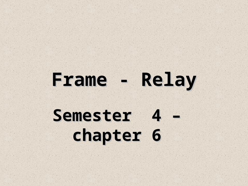
Frame - Relay. Semester 4 – chapter 6. Frame Relay Technology. What is a Frame – Relay ?. Introduction :. Circuit – switched services (T1):. Physical circuit must be established in advance between nodes (resources must be reserved). - PowerPoint PPT Presentation
Citation preview
Frame - RelayFrame - Relay
Semester 4 – chapter 6Semester 4 – chapter 6
Frame Relay TechnologyFrame Relay Technology
What is a Frame – Relay ?
Introduction:
Circuit – switched services (T1):
• Physical circuit must be established in advance between nodes (resources must be reserved).
• Resources are dedicated for each connection (bandwidth is not shared).
• In case of using leased lines (T1), a physical router interface is required for each destination node.
Frame-Relay (Packet – switched service):• Uses Virtual Circuits (VC) for data transmission (connection-oriented).
• Bandwidth can be shared by different sources.•Path is predetermined and well known for each destination.
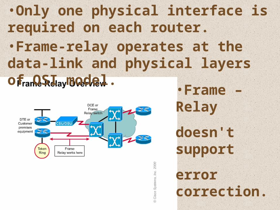
•Only one physical interface is required on each router.•Frame-relay operates at the data-link and physical layers of OSI model.
•Frame –Relay
doesn't support
error correction.
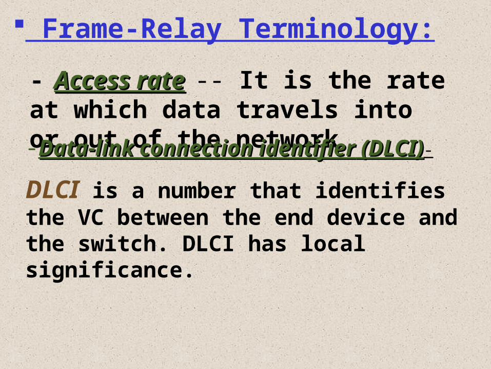
Frame-Relay Terminology:
- Access rateAccess rate -- It is the rate at which data travels into or out of the network.
-Data-link connection identifierData-link connection identifier (DLCI)(DLCI)-
DLCI is a number that identifies the VC between the end device and the switch. DLCI has local significance.
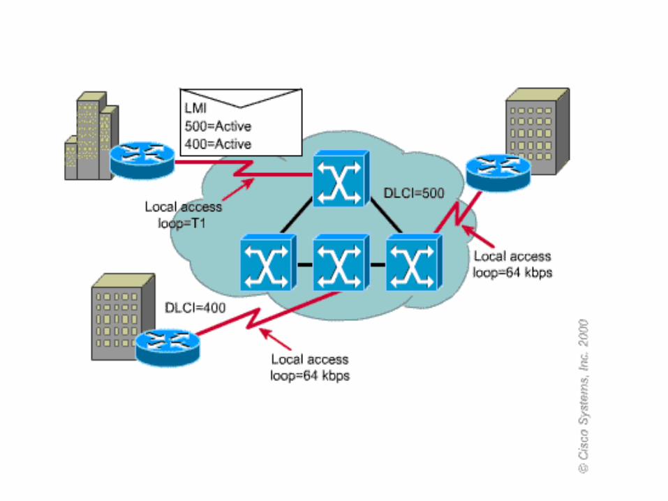
-LMILMI::Is a signaling standard between the frame relay switch and CPE.
Responsible for keepalive messages between the switch and CPE.
Ability to give DLCI global significance.
Keeps track of DLCIs status.
Three types of LMIs are supported:
and routers need to be told which LMI type is being used (In IOS 11.2 LMI is auto sensed).
ciscoansi
q933a
-Committed information rate (CIR):Committed information rate (CIR):
-Committed BurstCommitted Burst
The CIR is the guaranteed rate, in bits per second, that the service provider commits to providing.
The maximum number of bits that the switch agrees to transfer during a time interval.
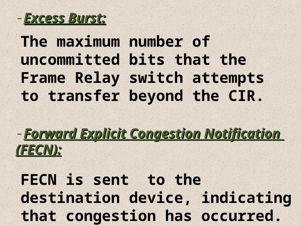
-Excess Burst:Excess Burst:
-Forward Explicit Congestion Forward Explicit Congestion Notification (FECN):Notification (FECN):
The maximum number of uncommitted bits that the Frame Relay switch attempts to transfer beyond the CIR.
FECN is sent to the destination device, indicating that congestion has occurred.
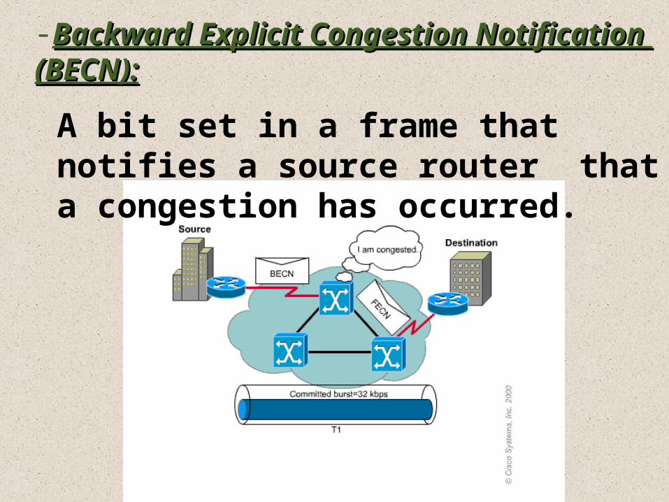
-Backward Explicit Congestion Backward Explicit Congestion Notification (BECN):Notification (BECN):
A bit set in a frame that notifies a source router that a congestion has occurred.
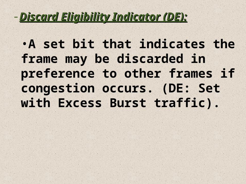
-Discard Eligibility Indicator (DE):Discard Eligibility Indicator (DE):
•A set bit that indicates the frame may be discarded in preference to other frames if congestion occurs. (DE: Set with Excess Burst traffic).
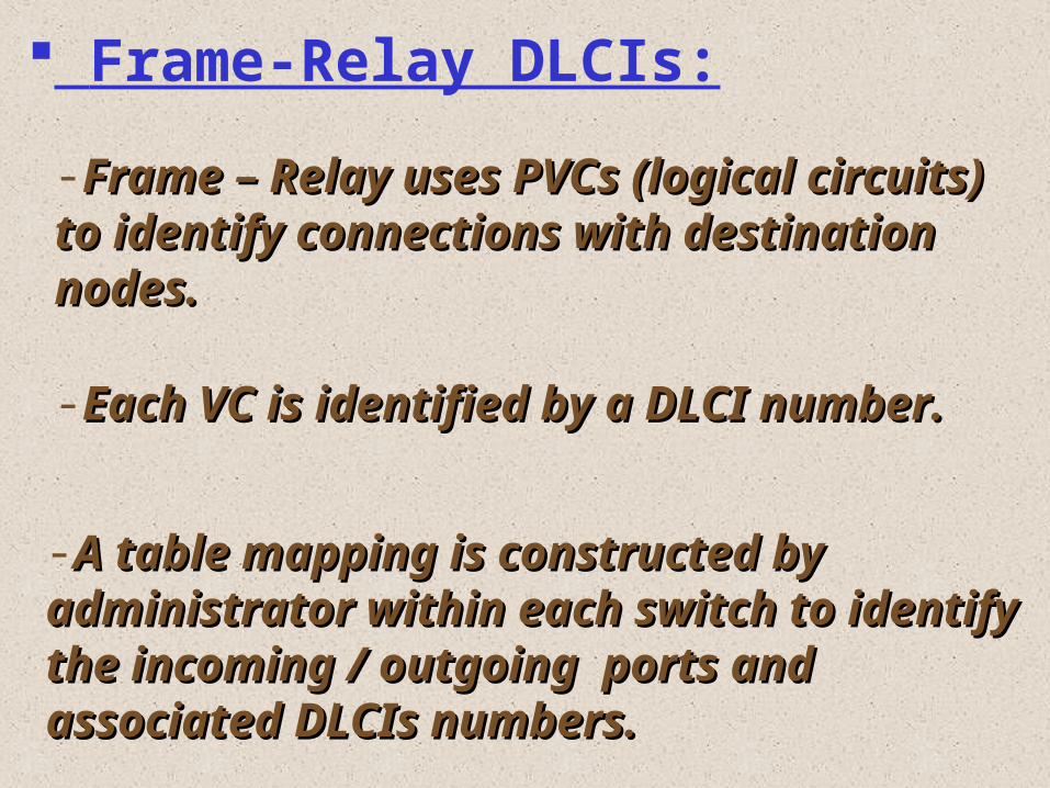
Frame-Relay DLCIs:
-Frame – Relay uses PVCs (logical Frame – Relay uses PVCs (logical circuits) to identify connections with circuits) to identify connections with destination nodes.destination nodes.
-Each VC is identified by a DLCI Each VC is identified by a DLCI number.number.
-A table mapping is constructed by A table mapping is constructed by administrator within each switch to administrator within each switch to identify the incoming / outgoing identify the incoming / outgoing ports and associated DLCIs numbers.ports and associated DLCIs numbers.
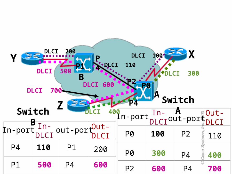
DLCI 100
DLCI 110
DLCI 200
A
B
In-port In-DLCI out-port
Out-DLCI
100P0 P2 110In-port In-
DLCIout-port Out-
DLCI
110P4 P1 200
Switch BSwitch A
DLCI 300
DLCI 400
P0 300 P4 400
DLCI 500
DLCI 600DLCI 700
P1 500 P4 600 P2 600 P4 700
P0P2
P4
P1P4 XY
Z
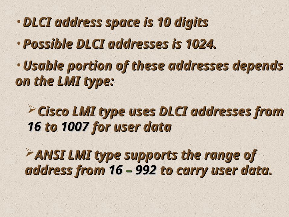
•DLCI address space is 10 digitsDLCI address space is 10 digits
•Possible DLCI addresses is 1024.Possible DLCI addresses is 1024.
•Usable portion of these addresses Usable portion of these addresses depends on the LMI type:depends on the LMI type:
Cisco LMI type uses DLCI addresses Cisco LMI type uses DLCI addresses fromfrom 1616 toto 10071007 for user datafor user data
ANSI LMI type supports the range ANSI LMI type supports the range of address fromof address from 1616 – – 992992 to carry to carry user data.user data.
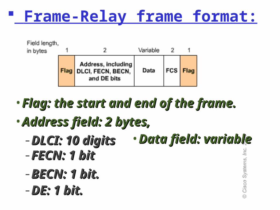
Frame-Relay frame format:
•Flag: the start and end of the frame.Flag: the start and end of the frame.•Address field: 2 bytes,Address field: 2 bytes,-DLCI: 10 digitsDLCI: 10 digits-FECN: 1 bitFECN: 1 bit-BECN: 1 bit.BECN: 1 bit.-DE: 1 bit.DE: 1 bit.
•Data field: Data field: variablevariable
LMI operationLMI operation
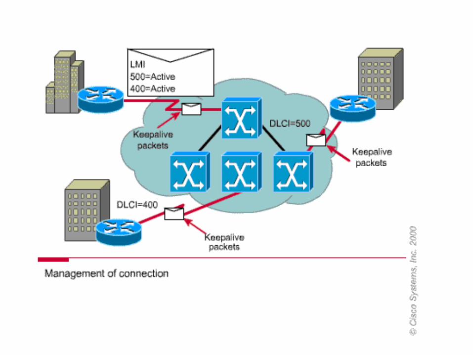
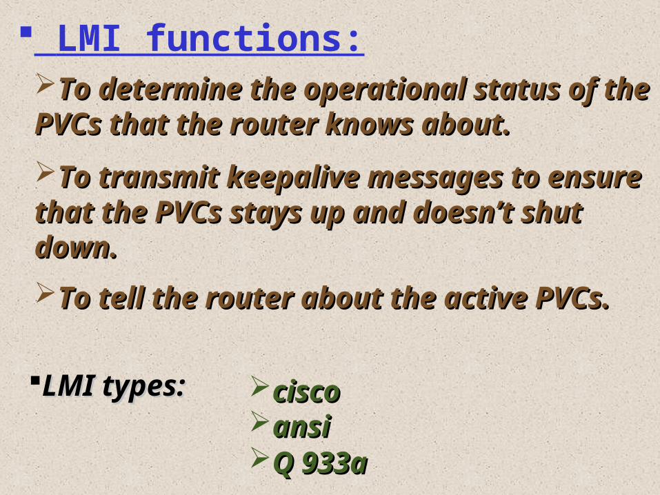
To determine the operational status To determine the operational status of the PVCs that the router knows of the PVCs that the router knows about.about.
LMI functions:
To transmit keepalive messages to To transmit keepalive messages to ensure that the PVCs stays up and ensure that the PVCs stays up and doesn’t shut down.doesn’t shut down.
To tell the router about the active To tell the router about the active PVCs.PVCs.
LMI types:LMI types: ciscociscoansiansiQ 933aQ 933a
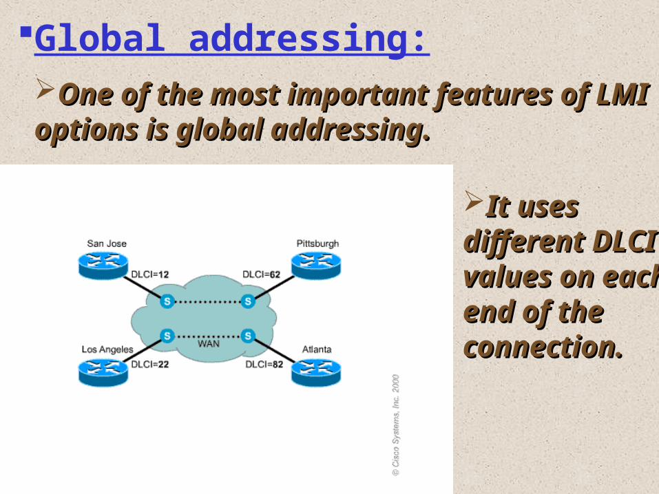
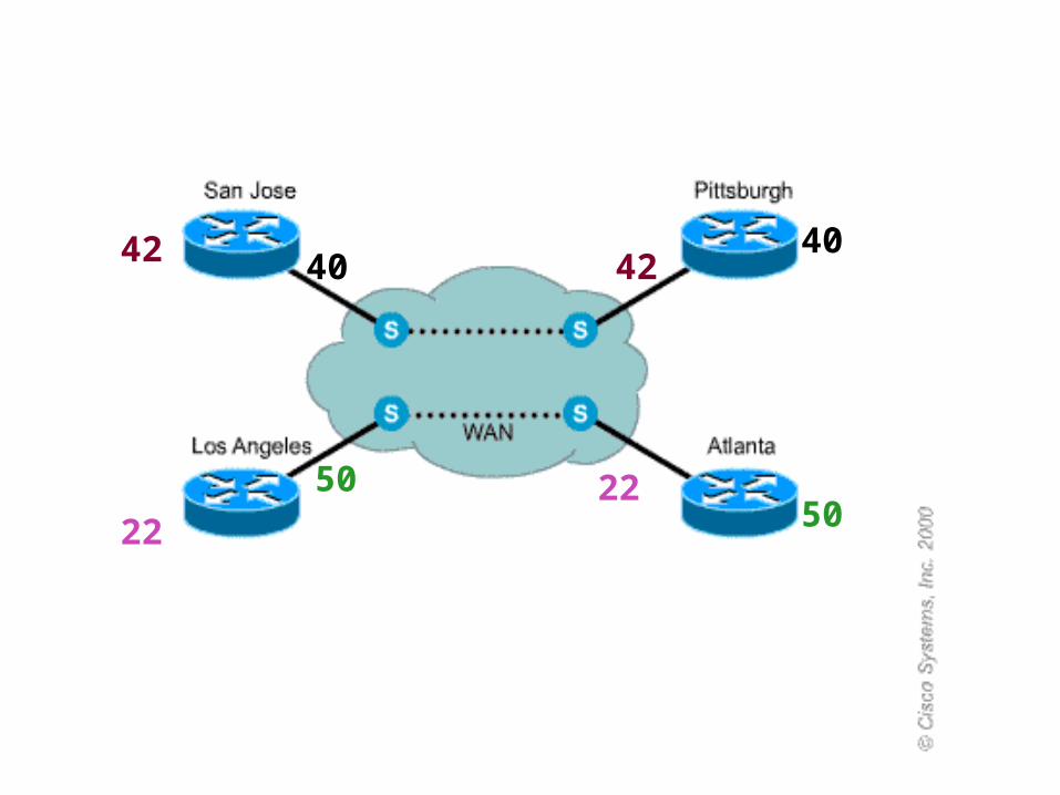
Global addressing:One of the most important features One of the most important features of LMI options is global addressing.of LMI options is global addressing.
It uses It uses different different DLCI values DLCI values on each end on each end of the of the connection.connection.
DLCIs are locally significant, needs DLCIs are locally significant, needs to be unique only on the same to be unique only on the same interface.interface.Global addressing makes DLCIs Global addressing makes DLCIs resemble the MAC address.resemble the MAC address.
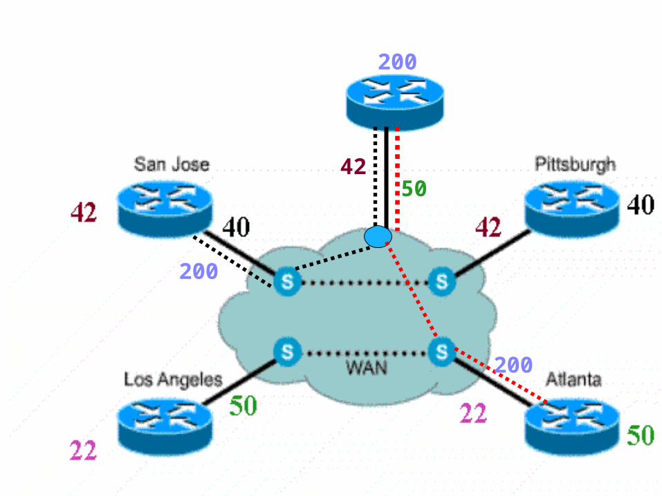
DLCI is assigned to the DTE not to DLCI is assigned to the DTE not to the access link and must be unique.the access link and must be unique.
Global address for one DTE means Global address for one DTE means that all DTEs with VC to this one that all DTEs with VC to this one DTE use its global address on their DTE use its global address on their access links.access links.
With normal addressing, a static With normal addressing, a static maps of destination IP address to maps of destination IP address to corresponding DLCI, must be corresponding DLCI, must be created.created.
4040
5050
42 42
2222
200
42
200
200
50
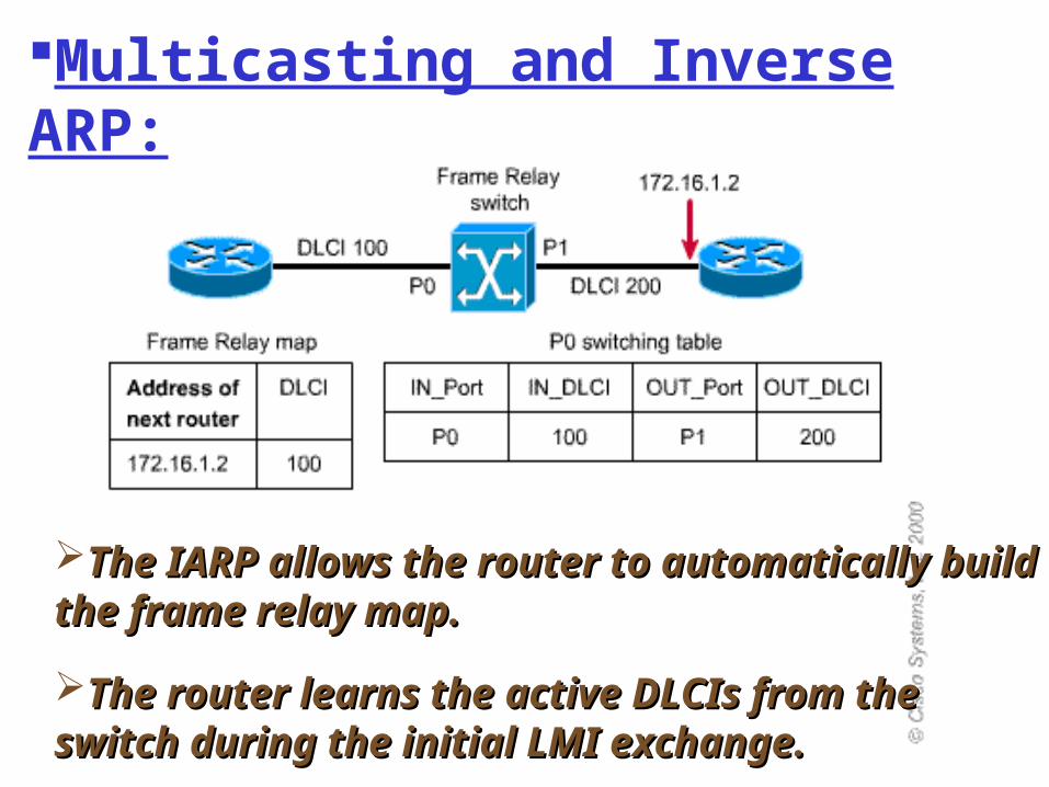
Multicasting and Inverse ARP:
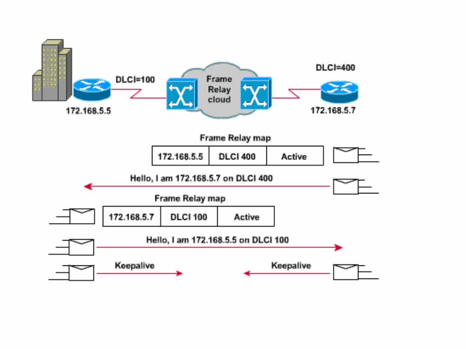
The IARP allows the router to The IARP allows the router to automatically build the frame relay map.automatically build the frame relay map.
The router learns the active DLCIs from The router learns the active DLCIs from the switch during the initial LMI the switch during the initial LMI exchange.exchange.
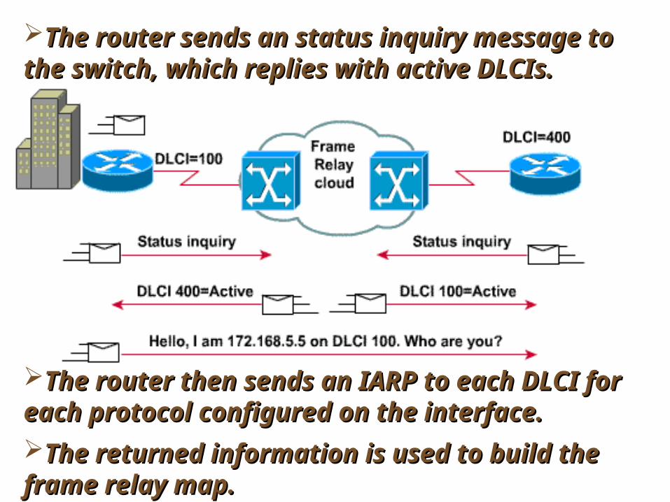
The router sends an status inquiry The router sends an status inquiry message to the switch, which replies with message to the switch, which replies with active DLCIs. active DLCIs.
The router then sends an IARP to each The router then sends an IARP to each DLCI for each protocol configured on the DLCI for each protocol configured on the interface. interface. The returned information is used to The returned information is used to build the frame relay map. build the frame relay map.
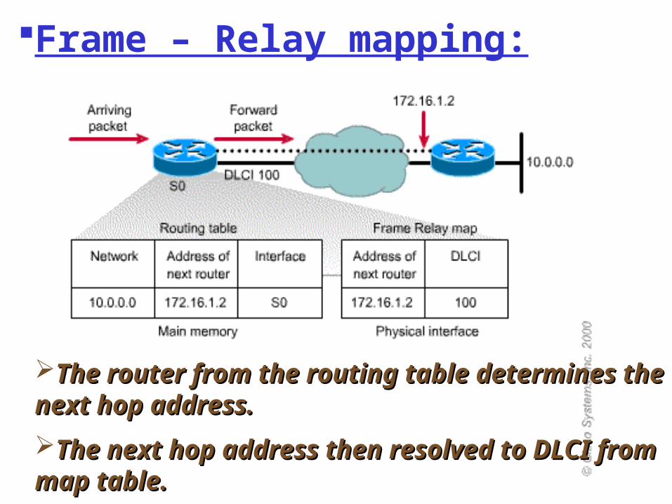
Frame – Relay mapping:
The router from the routing table The router from the routing table determines the next hop address. determines the next hop address.
The next hop address then resolved to The next hop address then resolved to DLCI from map table.DLCI from map table.
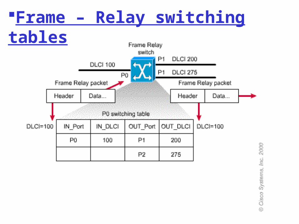
Frame – Relay switching tables
Frame – Relay Frame – Relay subinterfacessubinterfaces
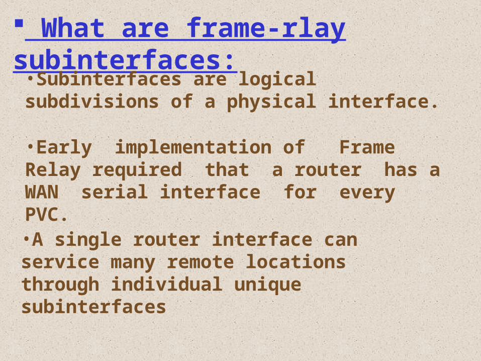
•Early implementation of Frame Relay required that a router has a WAN serial interface for every PVC.
What are frame-rlay subinterfaces:
•Subinterfaces are logical subdivisions of a physical interface.
•A single router interface can service many remote locations through individual unique subinterfaces
Configuration of subinterfaces:
Point – to – point , and
Multipoint configuration.
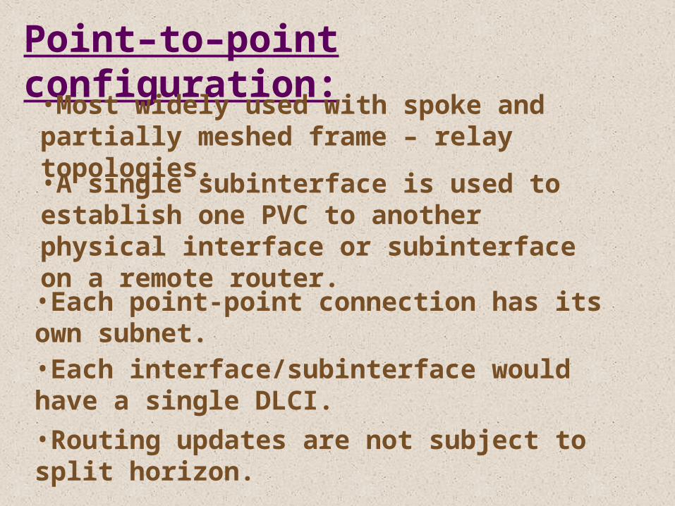
Point–to–point configuration:
•Most widely used with spoke and partially meshed frame – relay topologies.•A single subinterface is used to establish one PVC to another physical interface or subinterface on a remote router. •Each point-point connection has its own subnet. •Each interface/subinterface would have a single DLCI. •Routing updates are not subject to split horizon.
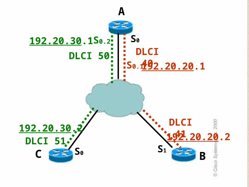
A
BC
S0
S1S0
DLCI 40
DLCI 41
S0.1
DLCI 50
DLCI 51
S0.2
192.20.20.1
192.20.20.2
192.20.30.1
192.20.30.2
A
BC S1S0
S0.1
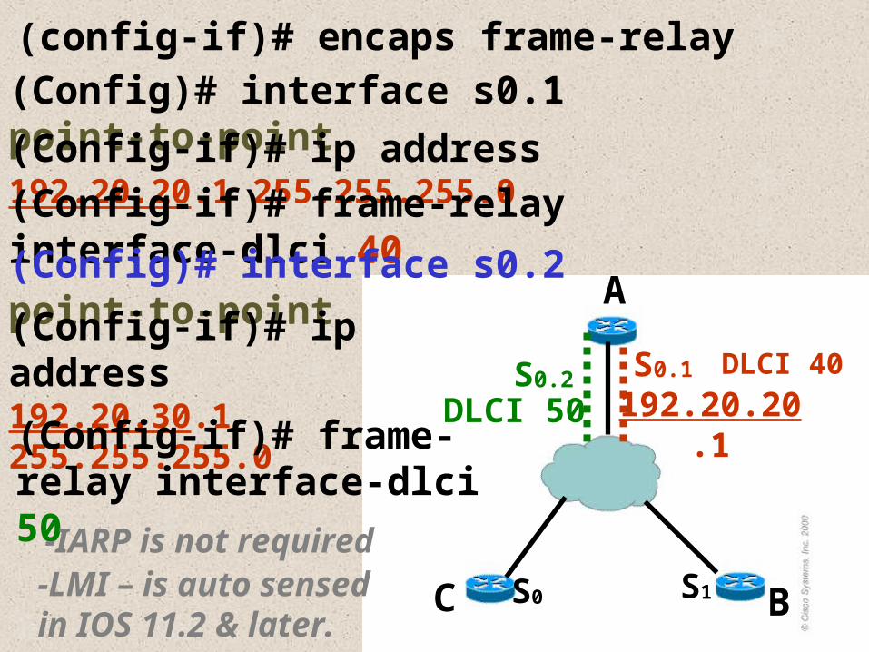
(config-if)# encaps frame-relay
(Config)# interface s0.1 point-to-point
(Config-if)# ip address 192.20.20.1 255.255.255.0
192.20.20.1
(Config-if)# frame-relay interface-dlci 40
DLCI 40
(Config)# interface s0.2 point-to-point
S0.2
(Config-if)# ip address 192.20.30.1 255.255.255.0
DLCI 50(Config-if)# frame-relay interface-dlci 50
-IARP is not required-LMI – is auto sensed in IOS 11.2 & later.
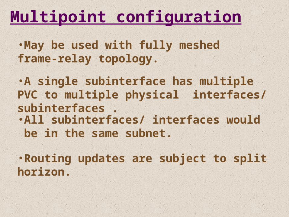
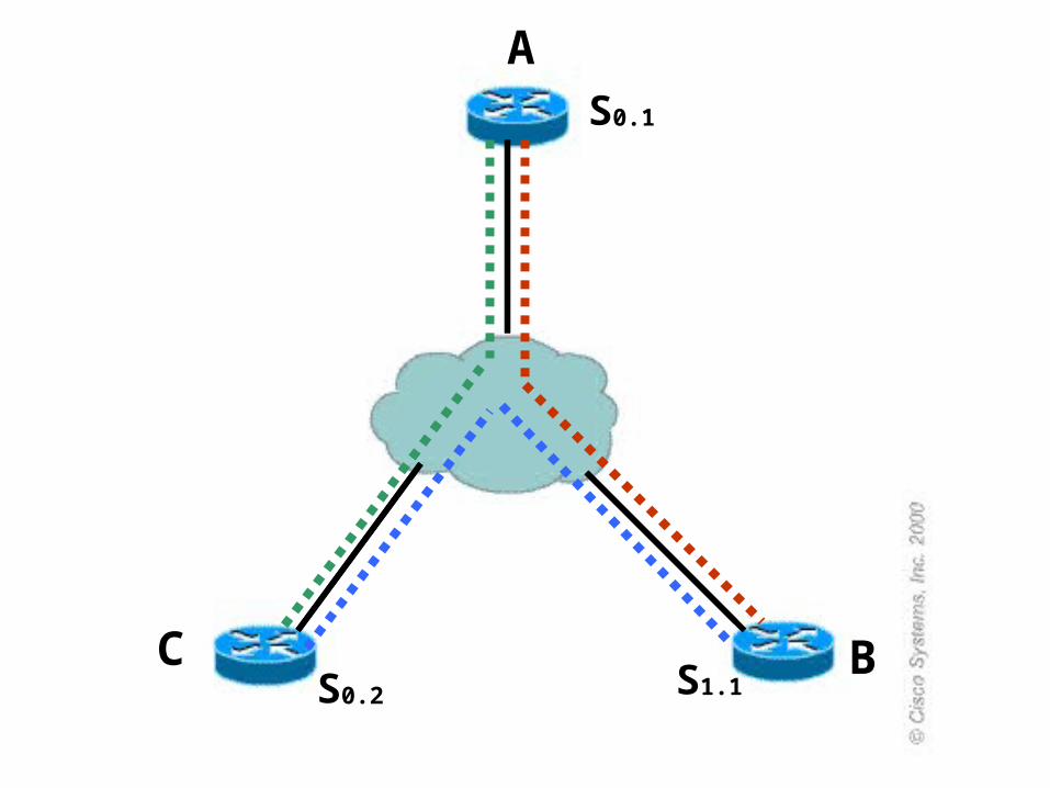
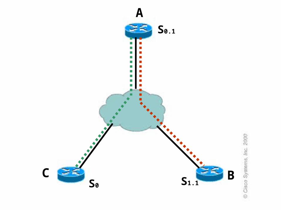
Multipoint configuration
•May be used with fully meshed frame-relay topology.
•A single subinterface has multiple PVC to multiple physical interfaces/ subinterfaces .•All subinterfaces/ interfaces would be in the same subnet.
•Routing updates are subject to split horizon.
A
BC
S0.1
S1.1S0.2
A
BC
S0.1
S1.1S0
A
BC
S0.1
S1.1S1
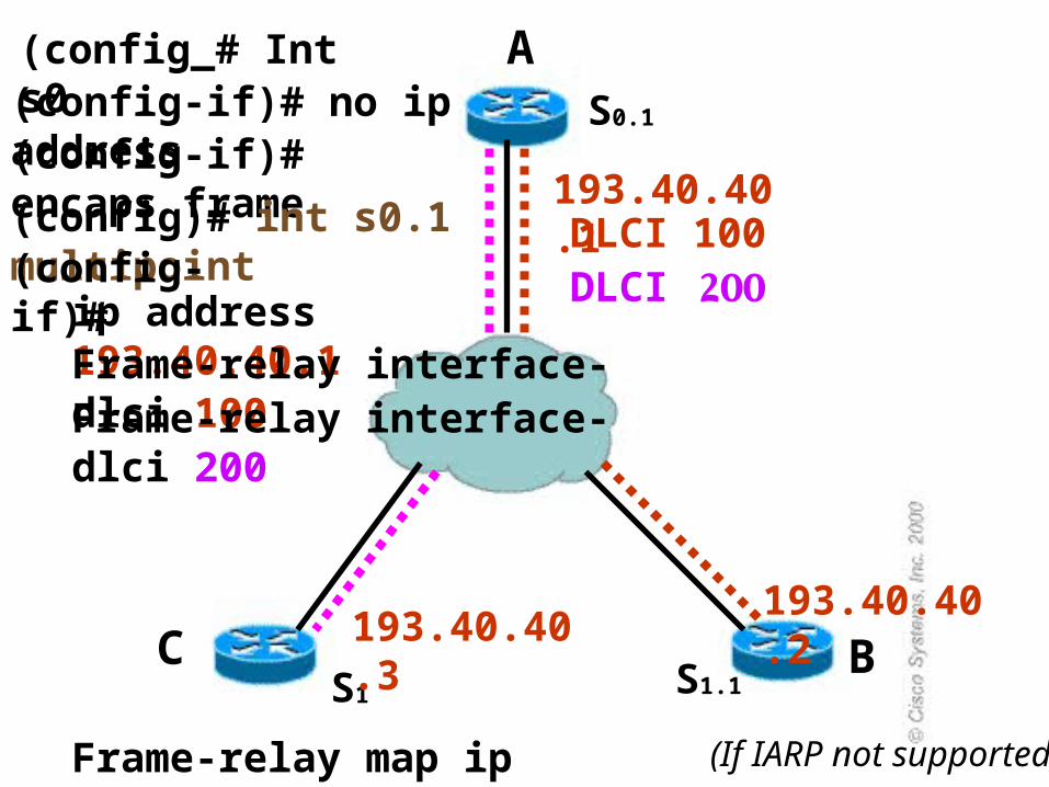
(config_# Int s0(config-if)# no ip address(config-if)# encaps frame
(config)# int s0.1 multipoint(config-if)#
193.40.40.1
193.40.40.2
ip address 193.40.40.1Frame-relay interface-dlci 100Frame-relay interface-dlci 200
DLCI 100DLCI 200
193.40.40.3
Frame-relay map ip 193.40.40.2 100 (If IARP not supported)
A
BC
S0.1
S1.1S1
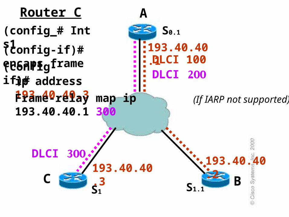
(config_# Int s1
(config-if)# encaps frame
(config-if)#
193.40.40.1
193.40.40.2
ip address 193.40.40.3
DLCI 100DLCI 200
193.40.40.3
Frame-relay map ip 193.40.40.1 300
DLCI 300
(If IARP not supported)
Router C

Good LuckGood Luck! !