Embed Size (px)
Citation preview
~ ~ -
Fracture toughness of denture base acrylics
G. D. Stafford and R. Huggett Department of Restorative Dentistry, Vental School, University of Wales. Cardiff, Wales B. E. Causton Department of Muterials Science in Dentistry, The London Hospital Medical College, University of London, England
Two types of fracture toughness specimen, the tapered cleavage (TC) and single edge notch (SEN), are compared. Their repro- ducibility, accuracy, and ease of preparation are investigated. The fracture toughness of four types of acrylic resin, heat cured, auto- polymerized, injection molded, and high impact resistant, has been determined by one or both of the above methods. High impact acrylic proved too ductile for either of the specimens to be used to assess K1,; however, these deviations from brittle be-
havior were revealed by the tests and some insight into impact resistance was gained. The SEN specimens proved capable of dis- tinguishing between the fracture toughness characteristics of the four types of denture base acrylics and proved easy to fabricate. The TC specimens proved difficult to fabri- cate requiring specialized equipment; however, once made, the specimens re- vealed more of the fracture process than did the SEN specimens.
INTRODUCTION
Denture base acrylics are subjected to many different types of stress in the mouth. These stresses may occur as a result of physical forces or chemical attack. Whatever the type of stress ultimate fracture of the denture will result because at one of the many flaws on the surface of the denture, stress has been concentrated to the point that crack growth can 0ccur.l
A large number of experiments on polymers have been reported that attempt to predict the degree of stress intensification required at the tip of the flaw to cause crack i n i t i a t i ~ n . ~ - ~ In addition the effect of te rnpera t~re ,~ molecular weight,6 degree of c r~ss l ink ing ,~ and rate of loading on the stress intensity factor ( K , ) have been reported.s
Most workers have used industrial poly(methy1 methacrylate) (PMM) in their evaluation of methods for determining K1, (the stress intensity at crack initiation). PMM in addition to being homogeneous has the advantages of availability, transparency, and a consistent molecular weight range.
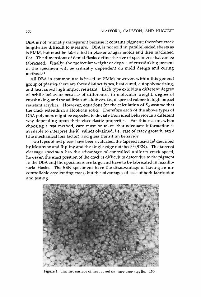
Denture base acrylic (DBA) has an heterogeneous m o r p h o l ~ g y ~ ~ ~ ~ (Fig. 1).
Journal of Biomedical Materials Research, Vol. 14,359-371 (1980) 0 1980 John Wiley & Sons, Inc. 002 1-9304 / 80 / 001 4-0359$0 1.30
360 STAFFORD, CAUSTON, AND HUGGETT
DBA is not normally transparent because it contains pigment; therefore crack lengths are difficult to measure. DBA is not sold in parallel-sided sheets as is PMM, but must be fabricated in plaster or agar molds and then machined flat. The dimensions of dental flasks define the size of specimens that can be fabricated. Finally, the molecular weight or degree of crosslinking present in the specimen will be critically dependent on mold design and curing method.ll
All DBA in common use is based on PMM; however, within this general group of plastics there are three distinct types, heat cured, autopolymerizing, and heat cured high impact resistant. Each type exhibits a different degree of brittle behavior because of differences in molecular weight, degree of crosslinking, and the addition of additives, i.e., dispersed rubber in high impact resistant acrylics. However, equations for the calculation of K , assume that the crack extends in a Hookean solid. Therefore each of the above types of DBA polymers might be expected to deviate from ideal behavior in a different way depending upon their viscoelastic properties. For this reason, when choosing a test method, care must be taken that adequate information is available to interpret the K , values obtained, i.e., rate of crack growth, tan 6 (the mechanical loss factor), and glass transition behavior.
Two types of test pieces have been evaluated, the tapered cleavage3 described by Mostovoy and Ripling and the single edge notched12 (SEN). The tapered cleavage specimen has the advantage of controlled uniform crack speed; however, the exact position of the crack is difficult to detect due to the pigment in the DBA and the specimens are large and have to be fabricated in maxillo- facial flasks. The SEN specimens have the disadvantage of having an un- controllable accelerating crack, but the advantages of ease of both fabrication and testing.
Figure 1. Fracture surface of heat cured denture base acrylic. 45X.
FRACTURE TOUGHNESS OF ACRYLICS 361
Theoretical
Inglis demonstrated that if a sheet under stress contains a crack, the stress will be intensified in the region of the crack and reach a maximum at the tip of the crack.13 This increase can be described by a single parameter K , pro- portional to the stress intensity factor. Under stress K increases until at break the intensification of local forces reach a critical value K , and the crack begins to increase in length. Griffithl related the K, to the critical strain energy re- lease rate (G,) of a growing crack.
K 2
E G, = (1 - v2) for plane strain
and
K C G, = - for plane stress E
where E = Young's modulus in bending and v = Poisson's ratio. These relations are important since G, is easier to determine than K , by direct methods.
Tapered cleavage specimen
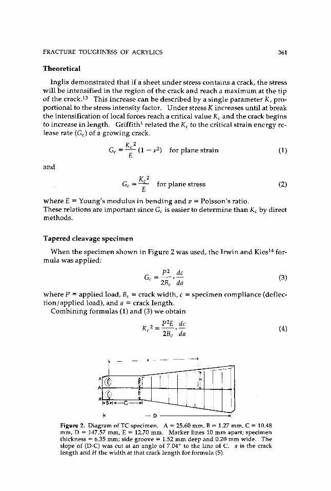
mula was applied: When the specimen shown in Figure 2 was used, the Irwin and Kies14 for-
P 2 d c 2 B , d a
G,=---.- (3)
where P = applied load, B, = crack width, c = specimen compliance (deflec- tion/applied load), and a = crack length.
Combining formulas (1) and (3) we obtain
P2E d c 2 B , d a
K,2 =-.- (4)
Figure 2. Diagram of TC specimen. A = 25.60 mm, B = 1.27 mm, C = 10.48 mm, D = 147.57 mm, E = 12.70 mm. Marker lines 10 mm apart; specimen thickness = 6.35 mm; side groove = 1.52 mm deep and 0.20 mm wide. The slope of (D-C) was cut at an angle of 7.04" to the line of C. a is the crack length aria H the width at that crack length for formula (5).
362 STAFFORD, CAUSTON, AND HUGGETT
To make the stress intensity factor independent of crack length, and the crack move through the specimen at a constant rate, the specimen is designed such that:
3a2 1 7 + - = const H H (5)
These conditions are only satisfied by a curved taper; however, the specimen used was a good approximation to the equation.
Two grooves cut in the sides of the specimen prevent crack deviation from the center line of the specimen.
Single edge notch specimen
Griffith has shown that for plane strain in a Hookean material'
2Ey(l - u2) U =
?ra
where (r = stress at failure and y = surface energy of crack formation,
G, = 2y
Substituting (7) and (1) in ( 6 ) we obtain
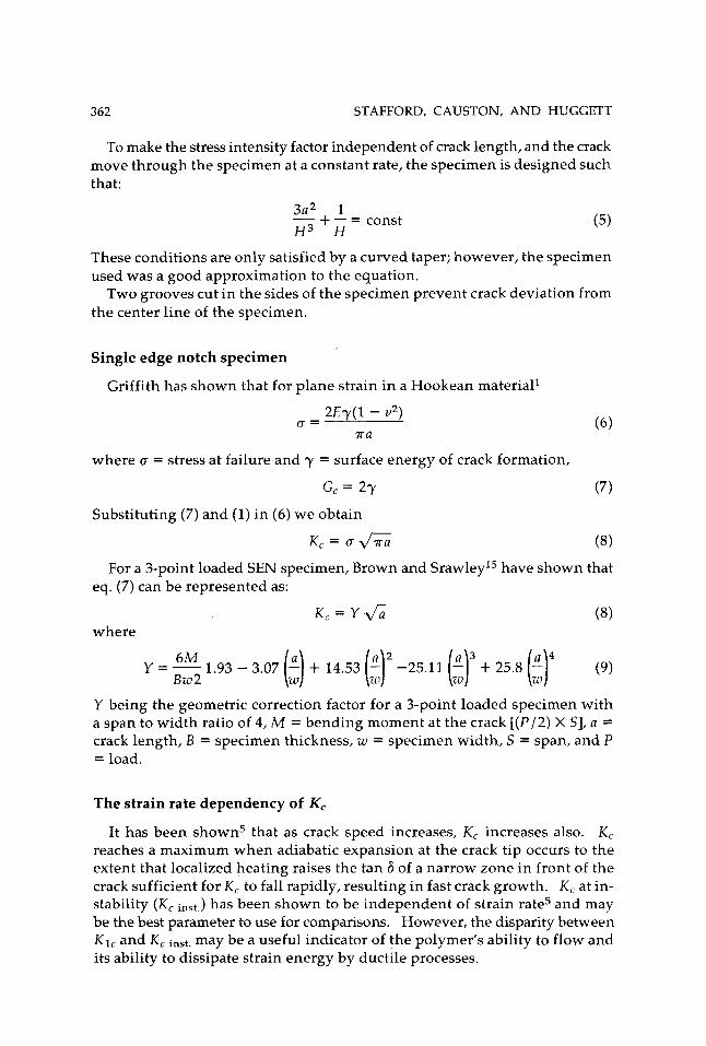
For a 3-point loaded SEN specimen, Brown and Srawley15 have shown that eq. (7) can be represented as:
K , = Y & where
6M y=- Bw2
Y being the geometric correction factor for a 3-point loaded specimen with a span to width ratio of 4, M = bending moment at the crack [(P/2) X S], a = crack length, B = specimen thickness, w = specimen width, S = span, and P = load.
The strain rate dependency of K,
It has been shown5 that as crack speed increases, K , increases also. K , reaches a maximum when adiabatic expansion at the crack tip occurs to the extent that localized heating raises the tan 6 of a narrow zone in front of the crack sufficient for K , to fall rapidly, resulting in fast crack growth. K , at in- stability ( K , inst.) has been shown to be independent of strain rate5 and may be the best parameter to use for comparisons. However, the disparity between K1, and K , inst. may be a useful indicator of the polymer's ability to flow and its ability to dissipate strain energy by ductile processes.
FRACTURE TOUGHNESS OF ACRYLICS 363
MATERIALS AND METHODS
Tapered cleavage experiment
Three polymers were tested using the tapered cleavage technique. Ho- mogeneous PMM" (A), a conventional heat cured DBAt (B), and a high impact resistant DBA* (C). The specimens were too large to be cured in standard dental flasks, and so maxillofacial flasks were used. For this reason samples of the autopolymerized and injection molded acrylic were not made. The PMM was tested dry and acted as a control for comparison with previously reported data.4J0 The conventional heat cured acrylic and the high impact material were equilibrated in water prior to testing, because in use denture base is wet and previous studies have shown that the K1, of wet DBA is greater than that of dry DBA.16
A sharp crack was introduced on the center line of each specimen using a wedge. This crack extended 1 cm along the specimen from the point of loading. The specimens were pulled apart in an Instron testing machine at a crosshead speed of 0.05 cmlmin. The chart was marked as the crack passed points on the specimen spaced 1 cm apart. This not only made it possible to calculate the compliance at each point but also the crack speed.
Single edge notch experiment
The three polymers tested in the tapered cleavage experiment were also tested using SEN specimens. In addition, two autopolymerized DBAs (D") (Et) and one injection molded acrylic (F*) were tested. These specimens were surface finished by hand on 600 grade silicon carbide paper. They were then centrally grooved on one face using a 45" angle cutter and the final dimensions are shown in Figure 3. Five samples of each acrylic were made and equili- brated in water. Twenty samples of PMM were made; ten were tested dry and ten were tested after equilibration in water.
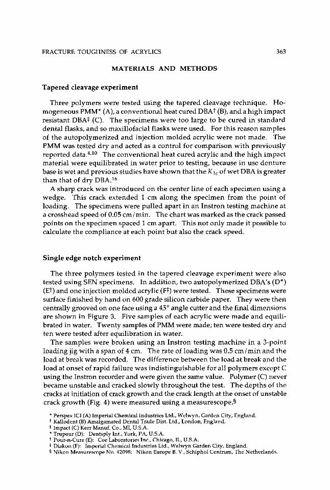
The samples were broken using an Instron testing machine in a 3-point loading jig with a span of 4 cm. The rate of loading was 0.5 cm/min and the load at break was recorded. The difference between the load at break and the load at onset of rapid failure was indistinguishable for all polymers except C using the Instron recorder and were given the same value. Polymer (C) never became unstable and cracked slowly throughout the test. The depths of the cracks at initiation of crack growth and the crack length at the onset of unstable crack growth (Fig. 4) were measured using a measurescope.5
* Perspex ICI (A) Imperial Chemical Industries Ltd., Welwyn, Garden City, England. t Kallodent (B) Amalgamated Dental Trade Dist. Ltd., London, England.
* Trupour (D): Dentsply Int., York, PA, U.S.A. t Pour-n-Cure (E): Coe Laboratories Inc., Chicago, IL, U.S.A. * Diakon (F): Imperial Chemical Industries Ltd., Welwyn Garden City, England. 5 Nikon Measurescope No. 42098: Nikon Europe B. V., Schiphol Centrum, The Netherlands
Impact (C) Kerr Manuf. Co., MI, U.S.A.
364
w_L
STAFFORD, CAUSTON, AND HUGGETT
Shape dependency experiment
Using a sharp crack specimen K, at instability was proved to be independent of strain rate. To determine whether this phenomenon is independent of sample geometry 30 SEN samples were cut from dry perspex; ten had the di- mensions 56 X 10 X 10 mm, ten the dimensions 56 X 5 X 5 mm, and ten the dimensions 28 X 5 X 5 mm. K1, and K, inst. was determined for each specimen size by the method described above.
RESULTS
The results of the tapered cleavage tests are given in Table I. The K1, values of dry PMM compare well with already published data on this materiaL4t6 The crack speeds are important in this test since the cracks are controlled and slow moving, and therefore are strain rate dependent.
Figure 4. Fracture surface of an SEN specimen showing position of crack at initiation (A) and position of crack at the onset of unstable crack growth (B). (Parabola are visible in portion beyond B.)
FRACTURE TOUGHNESS OF ACRYLICS 365
TABLE I Fracture Toughness Values Determined by Tapered Cleavage Method
K1, (MN/m3/2) Crack Speed Material Mean SD n mmlsec
Poly(methy1 methacrylate) (A) 1.13 0.10 6 0.12 Heat cured denture base acrylic (B) 1.49 0.01 5 0.11 High impact denture base acrylic (C) 3.98 + 8.13 1.62 4 0.02
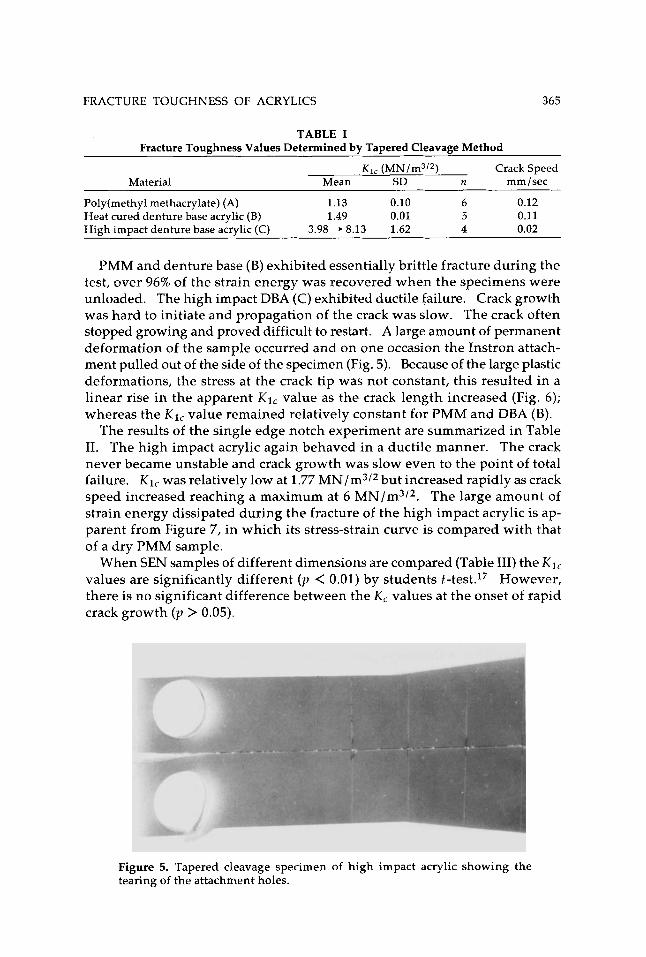
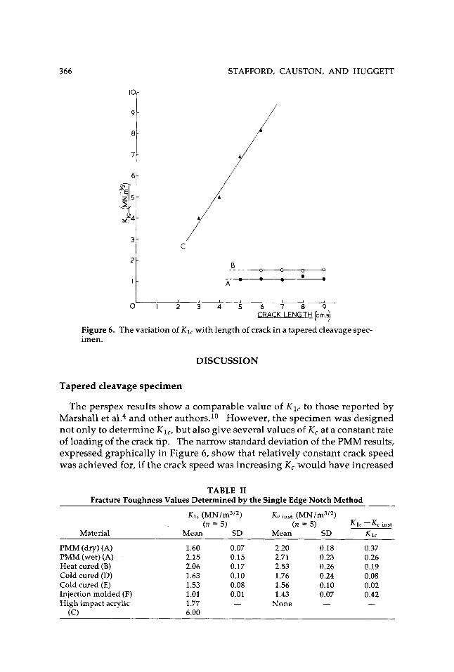
PMM and denture base (B) exhibited essentially brittle fracture during the test, over 96% of the strain energy was recovered when the specimens were unloaded. The high impact DBA (C) exhibited ductile failure. Crack growth was hard to initiate and propagation of the crack was slow. The crack often stopped growing and proved difficult to restart. A large amount of permanent deformation of the sample occurred and on one occasion the Instron attach- ment pulled out of the side of the specimen (Fig. 5). Because of the large plastic deformations, the stress at the crack tip was not constant, this resulted in a linear rise in the apparent K1, value as the crack length increased (Fig. 6); whereas the K 1 , value remained relatively constant for PMM and DBA (B).
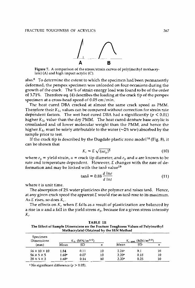
The results of the single edge notch experiment are summarized in Table 11. The high impact acrylic again behaved in a ductile manner. The crack never became unstable and crack growth was slow even to the point of total failure. K1, was relatively low at 1.77 MN/m3/2 but increased rapidly as crack speed increased reaching a maximum at 6 MN/m3/2. The large amount of strain energy dissipated during the fracture of the high impact acrylic is ap- parent from Figure 7, in which its stress-strain curve is compared with that of a dry PMM sample.
When SEN samples of different dimensions are compared (Table 111) the K1,
values are significantly different ( p < 0.01) by students t-test.17 However, there is no significant difference between the K , values at the onset of rapid crack growth ( p > 0.05).
Figure 5. Tapered cleavage specimen of high impact acrylic showing the tearing of the attachment holes.
366 STAFFORD, CAUSTON, AND HUGGETT
0 1 2 3 4 5 6 7 0 9 CRACK LENGTH (crn.9
Figure 6. The variation of K1, with length of crack in a tapered cleavage spec- imen.
DISCUSSION
Tapered cleavage specimen
The perspex results show a comparable value of K1, to those reported by Marshall et al.4 and other authors.1° However, the specimen was designed not only to determine KI, , but also give several values of K , at a constant rate of loading of the crack tip. The narrow standard deviation of the PMM results, expressed graphically in Figure 6, show that relatively constant crack speed was achieved for, if the crack speed was increasing K , would have increased
TABLE I1 Fracture Toughness Values Determined by the Single Edge Notch Method
K1, (MN/m3I2) K c inst. ( n = 5) ( n = 5) K1c --Kc inst.
Material Mean SD Mean SD K 1 ,
PMM (dry) (A) 1.60 PMM (wet) (A) 2.15 Heat cured (B) 2.06 Cold cured (D) 1.63 Cold cured (E) 1.53
High impact acrylic 1.77 (C) 6.00
Injection molded (F) 1.01
0.07 0.15 0.17 0.10 0.08 0.01 -
~ ~~~
2.20 0.18 2.71 0.23 2.53 0.26 1.76 0.24 1.56 0.10 1.43 0.07
None -
0.37 0.26 0.19 0.08 0.02 0.42
FRACTURE TOUGHNESS OF ACRYLICS 367
A B Figure 7. A comparison of the stress/strain curves of poly(methy1 methacry- late) (A) and high impact acrylic (C).
also8 To determine the extent to which the specimen had been permanently deformed, the perspex specimen was unloaded on four occasions during the growth of the crack. The % of strain energy load was found to be of the order of 3.71%. Therefore eq. (4) describes the loading at the crack tip of the perspex specimen at a cross-head speed of 0.05 cm/min.
The heat cured DBA cracked at almost the same crack speed as PMM. TherFfore their K1, values can be compared without correction for strain rate dependent factors. The wet heat cured DBA had a significantly ( p < 0.01) higher K1, value than the dry PMM. The heat cured denture base acrylic is crosslinked and of lower molecular weight than the PMM, and hence the higher K1, must be solely attributable to the water (-2% ww) absorbed by the sample prior to test.
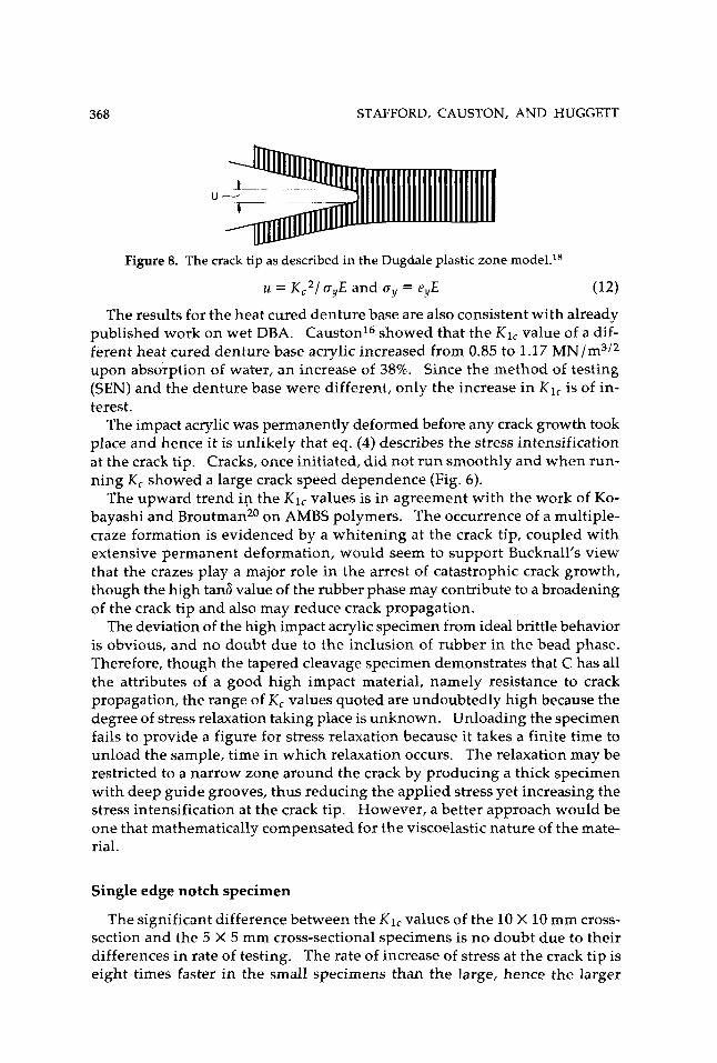
If the crack tip is described by the Dugdale plastic zone modells (Fig. 8), it can be shown that
K,=EJW (10) where ey = yield strain, u = crack tip diameter, and ey and u are known to be rate and temperature dependent. However, E changes with the rate of de- formation and may be linked with the tans value19
d lne tan6 = 0.88 -
d lnt where t is unit time.
The absorption of 2% water plasticizes the polymer and raises tan& Hence, at any given crack speed the apparent E would rise as tan6 rose to its maximum. As E rises, so does K,.
The effects on K , when E falls as a result of plasticization are balanced by a rise in u and a fall in the yield stress gy, because for a given stress intensity K C
TABLE I11 The Effect of Sample Dimensions on the Fracture Toughness Values of Poly(methy1
Methacrylate) Obtained by the SEN Method
Specimen Dimensions K 1 , (MN/m3I2) K c inst. (MN/m3’*)
Imm) Mean SD n Mean SD n
56 X 10 X 10 1.84 0.1 1 10 2.26a 0.1 10 5 6 X 5 X 5 1.60’ 0.07 10 2.20a 0.18 10 2 8 X 5 X 5 1.6ga 0.14 10 2.33a 0.25 10
a No significant difference ( p > 0.05).
368 STAFFORD, CAUSTON, AND HUGGETT
U
Figure 8. The crack tip as described in the Dugdale plastic zone rnodel.ls
u = K C 2 / ayE and uy = e,E (12)
The results for the heat cured denture base are also consistent with already published work on wet DBA. Causton16 showed that the K1, value of a dif- ferent heat cured denture base acrylic increased from 0.85 to 1.17 MN/m3/2 upon absorption of water, an increase of 38%. Since the method of testing (SEN) and the denture base were different, only the increase in K1, is of in- terest.
The impact acrylic was permanently deformed before any crack growth took place and hence it is unlikely that eq. (4) describes the stress intensification at the crack tip. Cracks, once initiated, did not run smoothly and when run- ning K, showed a large crack speed dependence (Fig. 6).
The upward trend in the K1, values is in agreement with the work of Ko- bayashi and Broutman20 on AMBS polymers. The occurrence of a multiple- craze formation is evidenced by a whitening at the crack tip, coupled with extensive permanent deformation, would seem to support Bucknall's view that the crazes play a major role in the arrest of catastrophic crack growth, though the high tan6 value of the rubber phase may contribute to a broadening of the crack tip and also may reduce crack propagation.
The deviation of the high impact acrylic specimen from ideal brittle behavior is obvious, and no doubt due to the inclusion of rubber in the bead phase. Therefore, though the tapered cleavage specimen demonstrates that C has all the attributes of a good high impact material, namely resistance to crack propagation, the range of K , values quoted are undoubtedly high because the degree of stress relaxation taking place is unknown. Unloading the specimen fails to provide a figure for stress relaxation because it takes a finite time to unload the sample, time in which relaxation occurs. The relaxation may be restricted to a narrow zone around the crack by producing a thick specimen with deep guide grooves, thus reducing the applied stress yet increasing the stress intensification at the crack tip. However, a better approach would be one that mathematically compensated for the viscoelastic nature of the mate- rial.
Single edge notch specimen
The significant difference between the KI, values of the 10 X 10 mm cross- section and the 5 X 5 mm cross-sectional specimens is no doubt due to their differences in rate of testing. The rate of increase of stress at the crack tip is eight times faster in the small specimens than the large, hence the larger
FRACTURE TOUGHNESS OF ACRYLICS 369
specimen has more time to dissipate strain energy by ductile processes. However, it is interesting to note that the K, instability of each of the three sizes of specimens proves to be independent of specimen size, and hence strain rate. This was predicted by Marshall et a1.8 and proved to be so using SEN specimens with sharp cracks (u = 1.6 pm). The phenomenon is therefore also true for blunt cracks (u = 5pm). The magnitude of K1, for dry PMM is very much higher than that found using tapered cleavage specimens. However, knowing the approximate values of u, eq. (12) allows an adjustment of K1, to be made to account for the bluntness of the SEN cracks, but no correction for strain rate is feasible for routine testing.
applying this correction to the dry perspex samples with the lowest strain rate the value for K1, is reduced from 1.60 to 0.91.
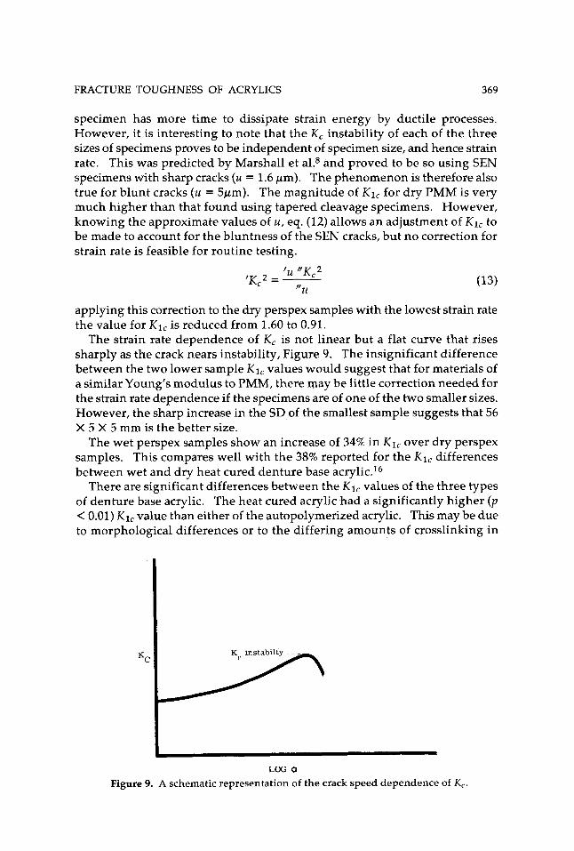
The strain rate dependence of K, is not linear but a flat curve that rises sharply as the crack nears instability, Figure 9. The insignificant difference between the two lower sample K1, values would suggest that for materials of a similar Young's modulus to PMM, there may be little correction needed for the strain rate dependence if the specimens are of one of the two smaller sizes. However, the sharp increase in the SD of the smallest sample suggests that 56 X 5 X 5 mm is the better size.
The wet perspex samples show an increase of 34% in K1, over dry perspex samples. This compares well with the 38% reported for the K1, differences between wet and dry heat cured denture base acrylic.I6
There are significant differences between the K1, values of the three types of denture base acrylic. The heat cured acrylic had a significantly higher ( p < 0.01) K1, value than either of the autopolymerized acrylic. This may be due to morphological differences or to the differing amounts of crosslinking in
LOG a Figure 9. A schematic representation of the crack speed dependence of K,.
370 STAFFORD, CAUSTON, AND HUGGETT
the interstitial matrix of the autopolymerized acrylic. It has been shown that heat cured acrylic is a graded series of interpenetrating polymer network^.^ Autopolymerized acrylics set before adequate monomer diffusion can occur and consist of linear polymer beads surrounded by an adherent crosslinked or branched phase. Kusy and Turner have also shown that heat cured acrylics fracture totally cohesively, whereas some degree of adhesive failure occurs in the autopolymerized acrylic.1° The differences between K1, and K, Inst, are smaller for the autopolymerized acrylics than for the heat cured acrylic, implying a more rapid acceleration in crack speed for the cold cured acrylics. This is possibly the result of a more branched or crosslinked interstitial ma- trix.7~11
The injection molded acrylic is more homogeneous than the denture base acrylics. However, its molecular weight (a,) is only 70,000; therefore, it is not surprising that its K1, value is very much lower than the others.6,21 The difference between K1, and K, inst. is large (50%) compared with that of perspex (25%), implying that considerable flow is possible before fracture occurs. The high impact acrylic once again exhibited a high degree of ductile behavior. Because the crack never became unstable only a range of Kl,’s can be given. However, since specimen geometry was not maintained, it is unlikely that shape factor Y was relevant for these specimens. All that can be said is that more energy was needed to break the impact specimen (Fig. 7). The wide range of Klc’s from a relatively low 1.77 MN/m3/2 rapidly rising to 6 MN/m3j2 suggests that crack initiation is easy, but the extreme strain rate dependency of K, rapidly slows the crack, preventing catastrophic failure.
CONCLUSIONS
Both the tapered cleavage and single edged notch specimens are capable of giving consistent and relevant values of K1, for denture base acrylics pro- vided they exhibit a high degree of elastic behavior.2 The single edged notch specimen was more convenient, but the tapered cleavage specimen is capable of greater control and gives a more precise view of the fracture process with regard to strain rate dependence.
Heat cured acrylic had a significantly higher fracture toughness than either the autopolymerized acrylic or the injection molded acrylic. The resistance of the acrylics to catastrophic failure followed the same pattern. However, the high impact acrylics are exceptional in this respect because neither type of specimen failed catastrophically.
References
1. A. A. Griffith, ”VI: The phenomena of rupture and flow in solids,” Philos. Trans. R. SOC. Ser. A, 221,163-198 (1921).
2. J. P. Berry, ”Fracture processes in polymer material. 11: The tensile strength of polystyrene,” J. Polym. Sci., 50,313-321 (1961).
3. S. Mostovoy and E. J. Ripling, ”Fracture toughness of an epoxy system,” J. Potym. Sci., 10,1351-1371 (1966).
FRACTURE TOUGHNESS OF ACRYLICS 371
4.
5.
6.
7.
8.
9.
10.
11.
12.
13.
14.
15.
16.
'17.
18.
19. 20.
21.
G. P. Marshall, L. E. Culver, and J. G. Williams, "Crack and craze propa- gation in polymers: a fracture-mechanics approach. 1: Crack growth in poly-(methylmethacrylate) in air," Plast. Polym., 37, (Pt. 127) 78-81 (1969). G. P. Marshall, L. H. Coutts, and J. G. Williams, "Temperature effects in the fracture of PMMA," J. Mater. Sci., 9,1409-1419 (1974). R. P. Kusy and D. T. Turner, "Influence of the molecular weight of poly- (methylmethacrylate) on fracture of surface energy in notched tension," Polymer, 17,161-166 (1976). J. P. Berry, "Fracture processes in polymer materials. IV: Dependence of the fracture surface energy on temperature and molecular structure," J. Polym. Sci., Part A, 1,993-1003 (1963). G. P. Marshall and J. G. Williams, "The correlation of fracture data for PMMA," J. Mater. Sci., 8,138-140 (1973). 8. E. Causton, "The physical and chemical properties of some polymeric dental materials," Ph.D. thesis, Faculty of Medicine, University of London (London Hospital Medical College), Chap. 2,1972. R. P. Kusy and D. T. Turner, "Fractography of two-phase acrylic polymers," J. Dent. Res., 53,520-529 (1974). R. P. Kusy, B. J. Lytwyn, and D. T. Turner, "Characterisation of cross-linked two-phase acrylic polymers," J. Dent. Res., 55,452-459 (1976). T. A. Freitag and S. L. Cannon, "Fracture characteristics of acrylic bone cements. 1. Fracture toughness," J. Biomed. Mater. Res., 10, 805-828 (1976). C. E. Inglis, "Stresses in a plate due to the presence of cracks and sharp corners," Trans. Inst. Naval Arch., 55,219-230 (1913) (DTSC-231-241). G. R. Irwin and J. A. Kies, "Fracturing and fracture dynamics," Welding
W. F. Brown and J., E. Srawley, "Plane strain crack toughness testing of high strength metallic materials," ASTM STP No. 470, ASTM, Philadelphia, 1967. B. E. Causton, "Fracture mechanics of dental poly(methy1 methacrylate)," J. Dent. Res., 54,339-343 (1975). J. Ipsen and P. Feigel, Bancrofts Introduction to Biostatistics, Harper and Row, New York, 1970. J. G. Williams, "Visco-elastic and thermal effects on crack growth in PMMA," Int. J. Fract. Mech., 8,393-401 (1972). M. Braden, personal communication, 1978. T. Kobayashi and L. J. Broutman, "Fracture studies in rubber-modified acrylics. 1: Experimental method; design of sandwich-tapered double- cantilever beam cleavage specimens," J. Polym. Sci., 17, 1909-1917 (1973). J. P. Berry, "Fracture processes in polymeric materials. V: Dependence of the ultimate properties of poly(methy1 methacrylate) on molecular weight," J. Polym. Sci., Part A, 2,4069-4076 (1964).
J., 31,95/S-lOO/S (1952).
Received March 16,1979 Accepted December 21,1979