Embed Size (px)
Citation preview
d e n t a l m a t e r i a l s 2 9 ( 2 0 1 3 ) 1244–1250
Available online at www.sciencedirect.com
ScienceDirect
jo ur nal ho me pag e: www.int l .e lsev ierhea l th .com/ journa ls /dema
Fracture risk of lithium-disilicate ceramic inlays:A finite element analysis
Christof Holberga,∗, Philipp Winterhaldera, Andrea Wichelhausa,Reinhard Hickelb, Karin Huthb
a Biomechanical Laboratory, Department of Orthodontics, School of Dentistry, University of Munich, Munich,Bavaria, Germanyb Department of Restorative Dentistry, School of Dentistry, University of Munich, Munich, Bavaria, Germany
a r t i c l e i n f o
Article history:
Received 11 November 2012
Received in revised form
1 March 2013
Accepted 18 September 2013
Keywords:
Lithium-disilicate
Ceramic inlay
Fracture risk
Preparation design
Parametric CAD modeling
Finite Element Method
Computer Aided Design
a b s t r a c t
Objectives. In the present study, lithium-disilicate ceramic inlays should be analyzed biome-
chanically according to their thickness and dimension, and it should be clarified as to
whether there is a significant relationship between the inlay volume and the induced tensile
stress level.
Methods. Using a new parametric CAD modeling procedure, 27 lithium-disilicate ceramic
inlays with various parameters of “depth”, “width”, “angle” and restoration volume were
generated. These inlays were integrated into the CAD model of a lower molar created from
the CT data of an anatomical preparation. The resulting CAD models were, finally, three-
dimensionally cross-linked to FEM models. After applying a compressive force of 200 N,
Principal Tensile Stresses (PTSs) could be measured in the inlay. The values were subject to
statistical analysis afterwards.
Results. The volume of the inlay restorations varied between 35.7 mm3 and 82.5 mm3. The
maximum PTS values (n = 10) only showed a slight negative correlation with the inlay vol-
ume. The correlation coefficient according to Spearman was −0.082 (p ≤ 0.001). If the highest
1000 PTS values of each inlay were considered (n = 1000), the correlation coefficient was fur-
ther reduced to +0.068 (p ≤ 0.001). No significant correlation between the inlay volume and
the induced PTS level could be detected.
Significance. Under the conditions and limitations of the present FEM study, the inlay volume
did not significantly influence the tensile stress level of ceramic inlays. The results may
support the thesis that volume-reduced all-ceramic inlays might not have an increased
fracture risk. Further studies are needed to confirm this.
emy
[1,4,5]. In addition to the indication, material suitability and
© 2013 Acad
1. Introduction
All-ceramic restorations have been approved for the treatmentof class II cavities. They can restore the natural morphology ofthe teeth, achieving both a high survival rate and a good visual
∗ Corresponding author at: Goethestrasse 70, 80336 Munich, Germany. TE-mail address: [email protected] (C. Holberg).
0109-5641/$ – see front matter © 2013 Academy of Dental Materials. Puhttp://dx.doi.org/10.1016/j.dental.2013.09.012
of Dental Materials. Published by Elsevier Ltd. All rights reserved.
appearance [1–3]. A fracture of the ceramic is a considerablecomplication, which can lead to the failure of the restoration
el.: +49 89 5160 3225; fax: +49 89 5160 7677.
quality of the adhesive bond, the form and dimension of thecavity preparation can have an effect on long-term success.The class II cavity preparation for full ceramic restoration can
blished by Elsevier Ltd. All rights reserved.
9 ( 2
bberm[a[etlbniufittwbasaIti
2
T(Tes
Fec
ing of the individual CAD models was done using parametriccoding (DWA from 111 to 333). The tooth enamel removed inthe virtual preparation was replaced anatomically by a virtual
d e n t a l m a t e r i a l s 2
e described parametrically using a basic form determinedy the parameters of depth, width and angle (DWA) [6]. How-ver, the volume of enamel and dentin removed by preparationemains mostly unknown. In vitro tests have shown that the
echanical stability of the tooth is reduced by the preparation7], but the adhesive bond between the ceramic restorationnd the enamel is able to re-establish the stability of the tooth8,9]. Nonetheless, the original tooth stability cannot be recov-red completely. The principle of each cavity preparation iso protect the natural enamel as far as possible [10], ofteneading to a gracile restoration. While gold inlays can almoste shaped in a gracile manner without fracturing [11], this isot the case with ceramic inlays [5]. Here, the stability of the
nlay depends upon its dimensions [8] and the type of ceramicsed [12]. Accordingly, the traditional preparation guidelinesor ceramic inlays are not as substance-friendly as with goldnlays, and often lead to considerable losses of enamel. Withhe continuous development of dental ceramics and innova-ive manufacturing processes [13], the question arises as tohether the preparation guidelines for ceramic inlays coulde adapted to minimally invasive treatment. Therefore, theim of the present study was to analyze various sizes andhapes of lithium-disilicate ceramic inlays biomechanically,nd to investigate the tensile stresses induced by mastication.n particular it should be clarified as to whether the risk of frac-ure is higher with volume-reduced lithium-disilicate ceramicnlays than with normally dimensioned ones.
. Materials and methods
he CT data from an anatomical preparation of the lower jawFig. 1) served as the morphological basis for the FEM models.
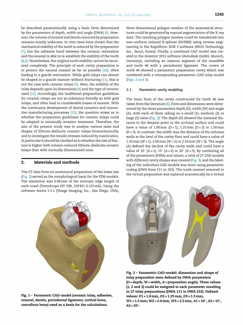
he resolution was 0.08 mm of the isotropic edge length ofach voxel (TomoScope HV 500, 220 kV; 0.125 mA). Using theoftware Amira 5.3.1 (Visage Imaging, Inc., San Diego, USA),ig. 1 – Parametric CAD-model (ceramic inlay, adhesive,namel, dentin, periodontal ligament, cortical bone,ancellous bone) used as a basis for the calculations.
0 1 3 ) 1244–1250 1245
three-dimensional polygon meshes of the anatomical struc-tures could be generated by manual segmentation of the X-raydata. The resulting polygon meshes could be transferred intonon-uniform rational B-splines (NURBS) using reverse engi-neering in the Rapidform XOR 3 software (INUS Technology,Inc., Seoul, Korea). Finally, a combined CAD model was cre-ated in the Inventor 2012 software (Autodesk GmbH, Munich,Germany), including an osseous segment of the mandibleand tooth 46 with a periodontal ligament. The crown oftooth 46 showed a parametric preparation cavity which wascombined with a corresponding parametric CAD inlay model(Figs. 2 and 3).
2.1. Parametric cavity modeling
The basic form of the cavity constructed for tooth 46 wastaken from the literature [6]. Form and dimensions were deter-mined by the three parameters depth (D), width (W) and angle(A), with each of them taking on a small (1), medium (2) orlarge (3) value (Fig. 2). The depth (D) showed the minimal dis-tance to the deepest point in the occlusal surface and couldhave a value of 1.00 mm (D = 1), 1.25 mm (D = 2) or 1.50 mm(D = 3). In contrast, the width was the distance of the isthmuswalls at the level of the cavity floor and could have a value of1.50 mm (W = 1), 2.00 mm (W = 2) or 2.50 mm (W = 3). The angle(A) defined the decline of the cavity walls and could have avalue of 10◦ (A = 1), 15◦ (A = 2) or 20◦ (A = 3). By combining allof the parameters (DWA) and values, a total of 27 CAD modelswith different cavity shapes was created (Fig. 3), and the label-
Fig. 2 – Parametric CAD-model: dimension and shape ofinlay preparation were defined by DWA-parameters(D = depth, W = width, A = preparation angle). Three values(1, 2 and 3) could be assigned to each parameter resultingin 27 inlay preparations (DWA 111 to DWA 333). Definedvalues: D1 = 1.0 mm, D2 = 1.25 mm, D3 = 1.5 mm,W1 = 1.5 mm; W2 = 2.0 mm, W3 = 2.5 mm, A1 = 10◦, A2 = 15◦,A3 = 20◦.
1246 d e n t a l m a t e r i a l s 2 9 ( 2 0 1 3 ) 1244–1250
Table 1 – Isotropic material properties used in all simulations: Young’s modulus specifies the elasticity of the materialand Poisson’s ratio specifies its transverse contraction characteristics.
Young’s modulus Poisson’s ratio References
Dentin 24.4 GPa 0.43 [19,25]LS2 ceramic (e.max Press) 91.0 GPa 0.23 [14]Nerve tissue 0.058 GPa 0.42 [18,22]
0.49 [16,24]0.25 [17]0.24 [23]
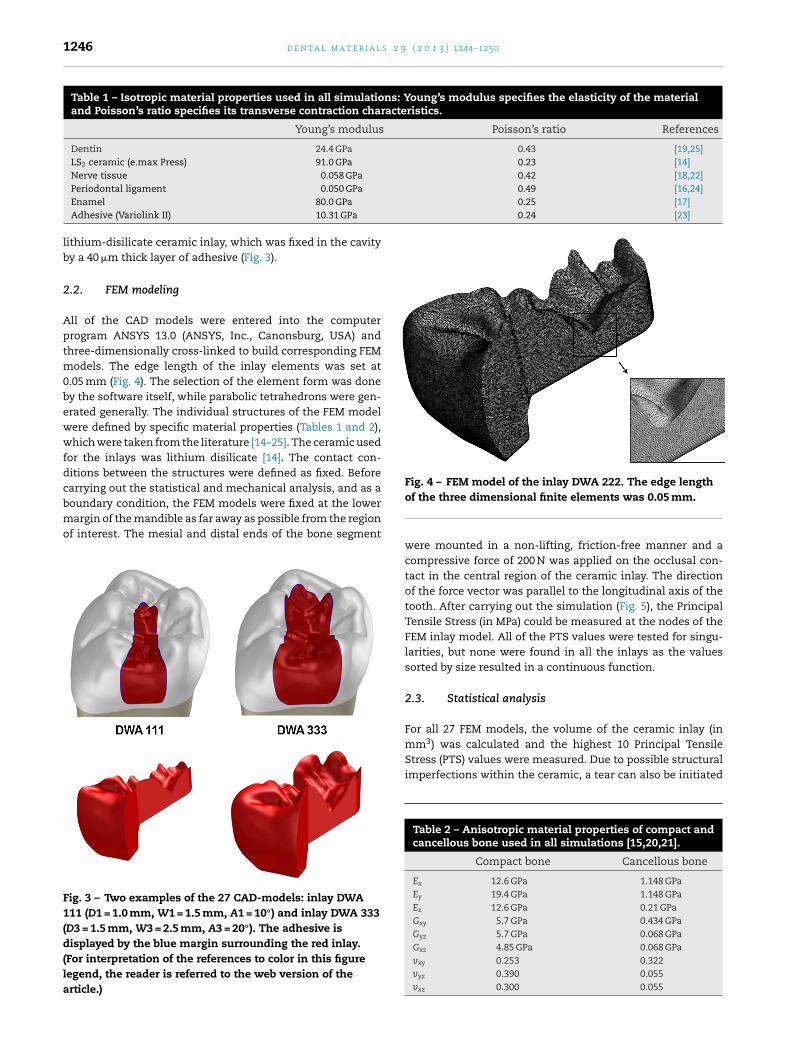
Fig. 4 – FEM model of the inlay DWA 222. The edge length
Periodontal ligament 0.050 GPa
Enamel 80.0 GPaAdhesive (Variolink II) 10.31 GPa
lithium-disilicate ceramic inlay, which was fixed in the cavityby a 40 �m thick layer of adhesive (Fig. 3).
2.2. FEM modeling
All of the CAD models were entered into the computerprogram ANSYS 13.0 (ANSYS, Inc., Canonsburg, USA) andthree-dimensionally cross-linked to build corresponding FEMmodels. The edge length of the inlay elements was set at0.05 mm (Fig. 4). The selection of the element form was doneby the software itself, while parabolic tetrahedrons were gen-erated generally. The individual structures of the FEM modelwere defined by specific material properties (Tables 1 and 2),which were taken from the literature [14–25]. The ceramic usedfor the inlays was lithium disilicate [14]. The contact con-ditions between the structures were defined as fixed. Beforecarrying out the statistical and mechanical analysis, and as a
boundary condition, the FEM models were fixed at the lowermargin of the mandible as far away as possible from the regionof interest. The mesial and distal ends of the bone segmentFig. 3 – Two examples of the 27 CAD-models: inlay DWA111 (D1 = 1.0 mm, W1 = 1.5 mm, A1 = 10◦) and inlay DWA 333(D3 = 1.5 mm, W3 = 2.5 mm, A3 = 20◦). The adhesive isdisplayed by the blue margin surrounding the red inlay.(For interpretation of the references to color in this figurelegend, the reader is referred to the web version of thearticle.)
of the three dimensional finite elements was 0.05 mm.
were mounted in a non-lifting, friction-free manner and acompressive force of 200 N was applied on the occlusal con-tact in the central region of the ceramic inlay. The directionof the force vector was parallel to the longitudinal axis of thetooth. After carrying out the simulation (Fig. 5), the PrincipalTensile Stress (in MPa) could be measured at the nodes of theFEM inlay model. All of the PTS values were tested for singu-larities, but none were found in all the inlays as the valuessorted by size resulted in a continuous function.
2.3. Statistical analysis
For all 27 FEM models, the volume of the ceramic inlay (in
mm3) was calculated and the highest 10 Principal TensileStress (PTS) values were measured. Due to possible structuralimperfections within the ceramic, a tear can also be initiatedTable 2 – Anisotropic material properties of compact andcancellous bone used in all simulations [15,20,21].
Compact bone Cancellous bone
Ex 12.6 GPa 1.148 GPaEy 19.4 GPa 1.148 GPaEz 12.6 GPa 0.21 GPaGxy 5.7 GPa 0.434 GPaGyz 5.7 GPa 0.068 GPaGxz 4.85 GPa 0.068 GPavxy 0.253 0.322vyz 0.390 0.055vxz 0.300 0.055
d e n t a l m a t e r i a l s 2 9 ( 2 0 1 3 ) 1244–1250 1247
Table 3 – Descriptive statistics of all inlays. Only the nodes with the highest 1000 values were statistically considered(n = 1000).
Inlay (DWA) Volume(mm3)
Elements Nodes n Mean(MPa)
Median(MPa)
SD (MPa) Min (MPa) Max (MPa)
111 35.68 2513946 3436435 1000 85.93 82.57 11.00 73.21 121.72112 39.32 2760141 3770545 1000 86.89 83.39 11.32 74.16 132.22113 43.04 3029442 4135864 1000 87.47 83.76 11.11 74.80 132.01121 46.88 3296942 4496796 1000 86.90 83.32 11.22 74.12 130.97122 50.82 3569901 4866641 1000 87.06 83.09 11.24 74.28 129.28123 54.97 3866478 5268892 1000 87.29 83.99 11.35 74.45 132.28131 58.98 4145188 5644779 1000 87.14 84.03 11.25 74.19 136.44132 63.24 4446687 6053683 1000 86.81 83.57 11.14 74.04 126.07133 67.89 4767963 6489048 1000 87.26 83.82 11.19 74.80 128.71211 39.38 2772525 3786712 1000 85.84 82.56 10.80 73.21 124.47212 43.71 3060791 4177898 1000 87.06 83.80 11.32 74.09 131.47213 47.93 3375077 4603367 1000 87.40 84.13 11.19 74.85 127.20221 51.67 3631954 4949002 1000 86.42 82.81 11.32 73.80 125.62222 56.35 3946091 5374061 1000 87.26 83.40 11.24 74.45 128.72223 60.87 4290408 5841203 1000 86.55 83.10 11.42 73.62 126.35231 64.90 4557607 6200988 1000 86.69 83.23 11.24 73.72 126.64232 69.88 4907382 6674346 1000 86.75 83.10 11.19 74.07 126.82233 75.14 5280173 7179642 1000 86.97 83.69 11.24 74.37 129.89311 43.10 3034943 4141352 1000 85.42 82.24 11.05 72.64 125.31312 47.71 3365798 4589774 1000 86.33 82.80 11.30 73.76 131.75313 53.00 3727179 5079232 1000 87.05 83.73 11.25 74.38 128.73321 56.51 3964626 5397726 1000 86.52 83.25 11.12 73.73 124.85322 61.72 4330006 5892321 1000 86.30 83.03 11.31 73.57 127.89323 67.20 4724292 6426672 1000 86.67 83.17 11.07 74.10 127.18
888
bfc(ctla
Fdfiv
331 70.77 4970283 6757195 1000
332 76.43 5370545 7299006 1000
333 82.47 5802512 7884044 1000
y slightly lower stress values than the maximum PTS. There-ore, the highest 1000 PTS values within each inlay were alsoonsidered for further statistical analysis. The analyzed nodesn = 1000) corresponded to an inlay volume of 0.01 mm3. Thealculated volumes and the measured PTS values were fed into
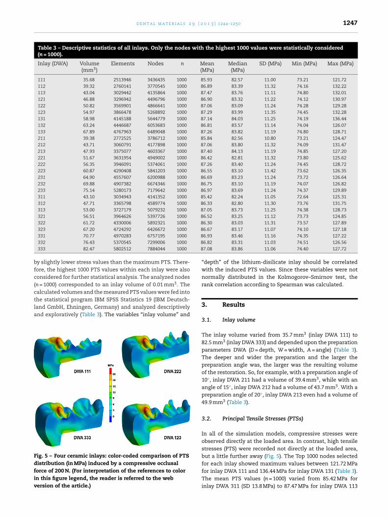
he statistical program IBM SPSS Statistics 19 (IBM Deutsch-and GmbH, Ehningen, Germany) and analyzed descriptivelynd exploratively (Table 3). The variables “inlay volume” andig. 5 – Four ceramic inlays: color-coded comparison of PTSistribution (in MPa) induced by a compressive occlusalorce of 200 N. (For interpretation of the references to colorn this figure legend, the reader is referred to the webersion of the article.)
6.93 83.46 11.16 74.35 127.226.82 83.31 11.03 74.51 126.567.08 83.86 11.06 74.40 127.72
“depth” of the lithium-disilicate inlay should be correlatedwith the induced PTS values. Since these variables were notnormally distributed in the Kolmogorov–Smirnov test, therank correlation according to Spearman was calculated.
3. Results
3.1. Inlay volume
The inlay volume varied from 35.7 mm3 (inlay DWA 111) to82.5 mm3 (inlay DWA 333) and depended upon the preparationparameters DWA (D = depth, W = width, A = angle) (Table 3).The deeper and wider the preparation and the larger thepreparation angle was, the larger was the resulting volumeof the restoration. So, for example, with a preparation angle of10◦, inlay DWA 211 had a volume of 39.4 mm3, while with anangle of 15◦, inlay DWA 212 had a volume of 43.7 mm3. With apreparation angle of 20◦, inlay DWA 213 even had a volume of49.9 mm3 (Table 3).
3.2. Principal Tensile Stresses (PTSs)
In all of the simulation models, compressive stresses wereobserved directly at the loaded area. In contrast, high tensilestresses (PTS) were recorded not directly at the loaded area,but a little further away (Fig. 5). The Top 1000 nodes selected
for each inlay showed maximum values between 121.72 MPafor inlay DWA 111 and 136.44 MPa for inlay DWA 131 (Table 3).The mean PTS values (n = 1000) varied from 85.42 MPa forinlay DWA 311 (SD 13.8 MPa) to 87.47 MPa for inlay DWA 113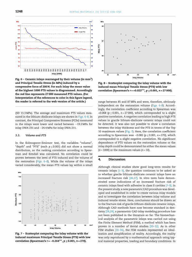
1248 d e n t a l m a t e r i a l s 2 9 ( 2 0 1 3 ) 1244–1250
Fig. 6 – Ceramic inlays rearranged by their volume (in mm3)and Principal Tensile Stress (in MPa) induced by acompressive force of 200 N. For each inlay the mean valueof the highest 1000 PTS values is diagrammed. Accordinglythe red line represents 27 000 measured PTS values. (Forinterpretation of the references to color in this figure legend,
Fig. 8 – Scatterplot comparing the inlay volume with theinduced mean Principal Tensile Stress (PTS) with low
the reader is referred to the web version of the article.)
(SD 13.3 MPa). The average and maximum PTS values mea-sured in the lithium-disilicate inlays are shown in Figs. 6–8. Incontrast, the Principal Compressive Stresses (PCSs) measuredin the inlays were lower and varied between −19.2 MPa forinlay DWA 231 and −24.4 MPa for inlay DWA 211.
3.3. Volume and PTS
In the Kolmogorov–Smirnov test, the variables “volume”,“depth” and “PTS” (each p ≤ 0.001) did not show a normaldistribution, so the ranking correlation according to Spear-man and Kendall was calculated. No correlation could be
proven between the level of PTS induced and the volume ofthe restoration (Figs. 6–8). While the volume of the inlaysvaried considerably, the mean PTS values lay within a smallFig. 7 – Scatterplot comparing the inlay volume with theinduced maximum Principal Tensile Stress (PTS) with lowcorrelation (Spearman’s r = −0.264***, p ≤ 0.001, n = 270).
correlation (Spearman’s r = +0.022***, p ≤ 0.001, n = 27 000).
range between 85 and 87 MPa and were, therefore, obviouslyindependent on the restoration volume (Figs. 6–8). Accord-ingly, the correlation coefficient according to Spearman was+0.068 (p ≤ 0.001, n = 27 000), which corresponded to a slightpositive correlation. A negative correlation leading to high PTSvalues in gracile lithium-disilicate ceramic inlays could notbe detected. It was also not possible to show a correlationbetween the inlay thickness and the PTS in terms of the Top10 maximum values (Fig. 7). Here, the correlation coefficientaccording to Spearman was −0.082 (p ≤ 0.001, n = 270), whichcorresponded to a slight negative correlation. No significantdependence of PTS values on the restoration volume or theinlay depth could be demonstrated for either the mean values(n = 1000) or the maximum values (n = 10).
4. Discussion
Although clinical studies show good long-term results forceramic inlays [1–3], the question continues to be asked asto whether gracile lithium-disilicate ceramic inlays have anincreased fracture risk [26,27]. In vitro tests have demon-strated some indications of an increased fracture risk ofceramic inlays fixed with adhesive in class II cavities [7–9]. Inthe present study, a new parametric CAD procedure was devel-oped and established in order to create various inlay modelsand to investigate the correlation between inlay volume andinduced tensile stress. Here, conclusions should be drawn asto the fracture risk of gracile lithium-disilicate ceramic inlays.Although CAD methods have now become standard in den-tistry [28,29], a parametric CAD inlay modeling procedure hasnot been published in the literature so far. The biomechan-ical analysis of the parametric inlays was carried out usingthe Finite Element Method (FEM), a method which has beenproven in a number of dental studies [30–32]. As in other
FEM studies [30–34], the FEM models represented an ideal-ization and simplification of reality. Accordingly, the realitywas only reproduced by a mathematical approach using typ-ical material properties, loading and boundary conditions. In
9 ( 2
ocetb[alu[iTv
4
Utpttt1sfcWalotttortmoipv
4
BlasrsirmTtcifsc
r
d e n t a l m a t e r i a l s 2
rder to keep the simplification effect as low as possible, thealculations were not limited to the tooth and the inlay, butxtended to other structures like the periodontal ligament andhe alveolar bone. The anisotropic material properties of theone [15,20,21] and the linear material properties of enamel
25], dentin [19], periodontal ligament [24], ceramic inlay [14],dhesive [23] and nerve tissue [18,22] could be taken from theiterature. Compared to other FEM studies, the FEM modelssed were more realistic in using patient individual CT data
30–32]. Considering the particular susceptibility of ceramicnlays to tensile stresses, this study calculated the Principalensile Stress (PTS) and not the Effective Stress according toan Mises.
.1. Inlay volume
sing the new parametric model generation method, the vir-ual preparation cavities could be created according to thearameters “depth”, “width” and “angle” (DWA). In additiono the standard preparation rules, the individual distance tohe pulp should also be taken into account when designinghe cavity. Therefore, the parameter “depth” was limited to.5 mm in the present study due to the individual dimen-ions of the pulpal cavity. During cavity preparation and theollowing treatment steps, the tooth is exposed to noxioushemical agents [6,27] or loaded mechanically and thermally.ith increasing proximity to the pulp, the risk of pulpal dam-
ge with resulting endodontic treatment and further enameloss is rising. This results in the clinical necessity of carryingut the cavity preparation as flatly as possible [27]. In con-rast, high values for the preparation angle and the width ofhe cavity transfer the restoration margin toward the den-al cusps. Corresponding to the individual occlusion protocolf the patient, the occlusal contacts can now occur on theestoration’s margin, making it necessary to further expandhe restoration. This results in the clinical necessity of not
aking the restoration too wide, at least initially [27,31]. Inrder to carry out the cavity preparation in as minimally
nvasive manner as possible, it is preferable to control thearameters during the preparation, thereby minimizing theolume of the substance loss [35,36].
.2. Principal Tensile Stress (PTS)
oth tensile and compressive stresses are induced in theithium-disilicate ceramic inlay as a result of the force appliedt the occlusal contact. During this process, the level of tensiletresses is the primary concern in terms of a potential mate-ial failure [37]. Directly below the loaded area, compressivetresses in particular were observed, but in the surround-ngs of this area tensile stresses dominated. This was theesult of a “stretching effect” caused by the minimal displace-
ent (“indent”) of the compressed area toward the dentin.herefore, relatively high tensile stresses were recorded in
he surroundings of the loaded region, but a tear in theeramic can also occur in regions further away due to defects
n the material structure of the ceramic [36,38]. The risk ofracture depends, therefore, not only upon the level of ten-ile stresses, but also upon the mechanical properties of theeramic and a lack of defects in the material structure [37].0 1 3 ) 1244–1250 1249
For all inlays, mostly “tensile stresses” but sometimes “com-pressive stresses” were measured at the control points. Thisdominance by “tensile stresses” was observed in all 27 inlays.Since the region of the applied force was kept constant in eachinlay, the margin of the restoration, the composite, the enameland the dentin had an individual distance to the applied forcevector. The wider the inlay and the further the restoration mar-gin away from the applied force, the lower were the PTS valuesthat were measured.
4.3. Inlay volume and PTS
The restoration volume and the induced PTS did not showa significant correlation for either the measured maximum(n = 10) or the mean PTS values (n = 1000). This implies thatthe highest stresses induced obviously do not depend uponthe dimensions of the lithium-disilicate ceramic inlay. Thepeak values measured in the gracile inlays were not higherthan those of the voluminous ones. Accordingly, the hypothe-sis that gracile lithium-disilicate inlays have an intrinsicallyincreased risk of fracture could not be confirmed by thepresent study. Volume-reduced lithium-disilicate ceramicinlays do not display higher tensile stresses than thicker ones.On the contrary: flat and gracile ceramic inlays spare theenamel, which in turn has a stabilizing effect on the ceramicrestoration [39].
5. Conclusion
Under the conditions and limitations of the present FEM study,the inlay volume was not an important factor influencing thetensile stress level of all-ceramic inlays. The results may sup-port the thesis that gracile all-ceramic inlays might not havean increased fracture risk and could be suitable for minimallyinvasive treatment. Further studies are needed to confirm this.
Acknowledgements
The results of the present study were decorated by a bestpaper award (2nd award) of the German Study Group Ceram-ics in Dental Science (AG Keramik in der Zahnheilkunde e.V.,D-76255 Ettlingen).
e f e r e n c e s
[1] Frankenberger R, Taschner M, Garcia-Godoy F, Petschelt A,Kramer N. Leucite-reinforced glass ceramic inlays andonlays after 12 years. J Adhes Dent 2008;10:393–8.
[2] Kramer N, Taschner M, Lohbauer U, Petschelt A,Frankenberger R. Totally bonded ceramic inlays and onlaysafter eight years. J Adhes Dent 2008;10:307–14.
[3] Land MF, Hopp CD. Survival rates of all-ceramic systemsdiffer by clinical indication and fabrication method. J Evid
Based Dent Pract 2010;10:37–8.[4] Beier US, Kapferer I, Dumfahrt H. Clinical long-termevaluation and failure characteristics of 1,335 all-ceramicrestorations. Int J Prosthodont 2012;25:70–8.
s 2 9
1250 d e n t a l m a t e r i a l[5] Boushell LW, Ritter AV. Ceramic inlays: a case presentationand lessons learned from the literature. J Esthet Restor Dent2009;21:77–87.
[6] Thompson MC, Thompson KM, Swain M. The all-ceramic,inlay supported fixed partial denture. Part 1. Ceramic inlaypreparation design: a literature review. Aust Dent J2010;55:120–7.
[7] Reel DC, Mitchell RJ. Fracture resistance of teeth restoredwith Class II composite restorations. J Prosthet Dent1989;61:177–80.
[8] Soares CJ, Martins LR, Fonseca RB, Correr-Sobrinho L,Fernandes Neta AJ. Influence of cavity preparation design onfracture resistance of posterior Leucite-reinforced ceramicrestorations. J Prosthet Dent 2006;95:421–9.
[9] St-Georges AJ, Sturdevant JR, Swift Jr EJ, Thompson JY.Fracture resistance of prepared teeth restored with bondedinlay restorations. J Prosthet Dent 2003;89:551–7.
[10] Momoi Y, Hayashi M, Fujitani M, Fukushima M, Imazato S,Kubo S, et al. Clinical guidelines for treating caries in adultsfollowing a minimal intervention policy—evidence andconsensus based report. J Dent 2012;40:95–105.
[11] Brackett MG, Kious AR, Brackett WW. Minimally retentivegold onlays: a six-year case report. Oper Dent 2009;34:352–5.
[12] Magne P, Paranhos MP, Schlichting LH. Influence of materialselection on the risk of inlay fracture duringpre-cementation functional occlusal tapping. Dent Mater2011;27:109–13.
[13] Edelhoff D, Brix O. All-ceramic restorations in differentindications: a case series. J Am Dent Assoc 2011;142:14S–9S.
[14] Albakry M, Guazzato M, Swain MV. Biaxial flexural strength,elastic moduli and X-ray diffraction characterization ofthree pressable all-ceramic materials. J Prosthet Dent2003;89:374–80.
[15] Dechow PC, Nail GA, Schwartz-Dabney CL, Ashman RB.Elastic properties of human supraorbital and mandibularbone. Am J Phys Anthropol 1993;90:291–306.
[16] Fill TS, Carey JP, Toogood RW, Major PW. Experimentallydetermined mechanical properties of, and models for, theperiodontal ligament: critical review of current literature. JDent Biomech 2011;2011:312980.
[17] He LH, Fujisawa N, Swain MV. Elastic modulus andstress–strain response of human enamel bynano-indentation. Biomaterials 2006;27:4388–98.
[18] Ichihara K, Taguchi T, Shimada Y, Sakuramoto I, Kawano S,Kawai S. Gray matter of the bovine cervical spinal cord ismechanically more rigid and fragile than the white matter. JNeurotrauma 2001;18:361–7.
[19] Kinney JH, Gladden JR, Marshall GW, Marshall SJ, So JH,Maynard JD. Resonant ultrasound spectroscopymeasurements of the elastic constants of human dentin. JBiomech 2004;37:437–41.
[20] O’Mahony AM, Williams JL, Katz JO, Spencer P. Anisotropic
elastic properties of cancellous bone from a humanedentulous mandible. Clin Oral Implants Res 2000;11:415–21.[21] O’Mahony AM, Williams JL, Spencer P. Anisotropic elasticityof cortical and cancellous bone in the posterior mandible
( 2 0 1 3 ) 1244–1250
increases peri-implant stress and strain under obliqueloading. Clin Oral Implants Res 2001;12:648–57.
[22] Borschel GH, Kia KF, Kuzon WM, Dennis RG. Mechanicalproperties of acellular peripheral nerve. J Surg Res2003;114:133–9.
[23] Oztürk E, Hickel R, Bolay S, Ilie N. Micromechanicalproperties of veneer luting resins after curing throughceramics. Clin Oral Investig 2012;16:139–46.
[24] Rees JS, Jacobsen PH. Elastic modulus of the periodontalligament. Biomaterials 1997;18:995–9.
[25] Xu HH, Smith DT, Jahanmir S, Romberg E, Kelly JR,Thompson VP, et al. Indentation damage and mechanicalproperties of human enamel and dentin. J Dent Res1998;77:472–80.
[26] Esquivel-Upshaw JF, Anusavice KJ, Yang MC, Lee RB. Fractureresistance of all-ceramic and metal-ceramic inlays. Int JProsthodont 2001;14:109–14.
[27] Arnetzl GV, Arnetzl G. Design of preparations for all-ceramicinlay materials. Int J Comput Dent 2006;9:289–98.
[28] Hickel R, Dasch W, Mehl A, Kremers L. CAD/CAM—fillings ofthe future? Int Dent J 1997;47:247–58.
[29] Mehl A, Blanz V. New procedure for fully automatic occlusalsurface reconstruction by means of a biogeneric toothmodel. Int J Comput Dent 2005;8:13–25.
[30] Magne P, Perakis N, Belser UC, Krejci I. Stress distribution ofinlay-anchored adhesive fixed partial dentures: a finiteelement analysis of the influence of restorative materialsand abutment preparation design. J Prosthet Dent2002;87:516–27.
[31] Arnetzl GV, Arnetzl G. Biomechanical examination of inlaygeometries—is there a basic biomechanical principle? Int JComput Dent 2009;12:119–30.
[32] Ona M, Watanabe C, Igarashi Y, Wakabayashi N. Influence ofpreparation design on failure risks of ceramic inlays: a finiteelement analysis. J Adhes Dent 2011;13:367–73.
[33] Dejak B, Mlotkowski A. Three-dimensional finite elementanalysis of strength and adhesion of composite resinversus ceramic inlays in molars. J Prosthet Dent2008;99:131–40.
[34] Seow LL, Toh CG, Fok AS, Wilson NH. A finite elementanalysis of ceramic restorations in endodontically treatedpremolars. Am J Dent 2008;21:331–6.
[35] Syrek A, Reich G, Ranftl D, Klein C, Cerny B, Brodesser J.Clinical evaluation of all-ceramic crowns fabricated fromintraoral digital impressions based on the principle of activewavefront sampling. J Dent 2010;38:553–9.
[36] Gonzaga CC, Cesar PF, Miranda Jr WG, Yoshimura HN. Slowcrack growth and reliability of dental ceramics. Dent Mater2011;27:394–406.
[37] Gabbert O, Ohlmann B, Schmitter M, Farhan D, Becker F,Rammelsberg P. Effect of gingival ceramic veneer thicknesson the fracture strength of zirconia-based fixed dentalprostheses. Am J Dent 2010;23:147–51.
[38] Peters MC, de Vree JH, Brekelmans WA. Distributed crack
analysis of ceramic inlays. J Dent Res 1993;72:1537–42.[39] Mehl A, Kunzelmann KH, Folwaczny M, Hickel R.Stabilization effects of CAD/CAM ceramic restorations inextended MOD cavities. J Adhes Dent 2004;6:239–45.


![A pilot trial on lithium disilicate partial crowns using a novel … · 2019. 12. 9. · lithium disilicate material (Initial LiSi press, GC) has been reported [8]. Only few clinical](https://img.pdfslide.us/doc/110x75/611d4130777ab743257f5b01/a-pilot-trial-on-lithium-disilicate-partial-crowns-using-a-novel-2019-12-9.jpg)


![Phase equilibria in the subsystem barium disilicate - … · Phase Equilibria in the Subsystem Barium Disilicate ... cation [8] polymorphism in barium disilicate was an nounced. T](https://img.pdfslide.us/doc/110x75/5b5b4ac67f8b9a302a8da3fa/phase-equilibria-in-the-subsystem-barium-disilicate-phase-equilibria-in-the.jpg)