Embed Size (px)
Citation preview
Fracture Resistance of Non-Metallic Molar
Crowns Manufactured with CEREC 3D
Dalia A. Madani, BSc, DDS
A thesis submitted in conformity with the requirements
for the degree of Master in Science
Graduate Department of Biomaterials
Faculty of Dentistry
University of Toronto
© Copyright by Dalia Madani (2010)
Fracture Resistance of Non-Metallic Molar Crowns Manufactured withCEREC 3D
Dalia A. MadaniMaster of Science
Graduate Department of Biomaterials, Faculty of DentistryUniversity of Toronto
2010
Abstract
Objectives: To compare fracture strength and fatigue resistance of ce-
ramic (ProCAD, Ivoclar-Vivadent)(C) and resin composite (ParadigmMZ100,
3M/ ESPE)(R) crowns made with CEREC-3D.Methods: A prepared ivorine
molar tooth was duplicated to produce 40 identical prepared specimens made
of epoxy resin (Viade). Twenty (C) crowns and 20 (R) were cemented to their
dies using resin cement. Ten of each group were subjected to compressive
loading to fracture. The remaining 10 of each group were subjected to me-
chanical cyclic loading for 500,000 cycles. The survivors were subjected to
compressive loading to fracture. Results: No signi�cant di�erence in mean
fracture load was found between the two materials. However, only 30% of
the (C) crowns vs. 100% of the (R) crowns survived the cyclic loading test.
Conclusions: (R) crowns demonstrated higher fatigue Resistance than (C)
crowns in-vitro and might better resist cracking in-vivo.
ii
Contents
1 Introduction 1
1.1 Background . . . . . . . . . . . . . . . . . . . . . . . . . . . . 1
1.2 Porcelain-Fused-to-Metal Restorations . . . . . . . . . . . . . 3
1.2.1 Advantages of Porcelain-Fused-to-Metal Restorations . 3
1.2.2 Limitations of Porcelain-Fused-to-Metal Restorations . 4
1.3 History of the CEREC technology . . . . . . . . . . . . . . . 4
1.3.1 CEREC I . . . . . . . . . . . . . . . . . . . . . . . . . 5
1.3.2 CEREC II . . . . . . . . . . . . . . . . . . . . . . . . . 6
1.3.3 CEREC III . . . . . . . . . . . . . . . . . . . . . . . . 7
1.4 Advantages and Limitations of the CEREC technology . . . . 9
1.4.1 Advantages of the CEREC technology . . . . . . . . . 9
1.4.2 Limitations of the CEREC technology . . . . . . . . . 12
1.5 Materials Used for Chair-side CEREC . . . . . . . . . . . . . 13
1.5.1 Ceramics . . . . . . . . . . . . . . . . . . . . . . . . . . 14
1.5.2 Composite Resin . . . . . . . . . . . . . . . . . . . . . 18
1.6 Concerns of the current CEREC materials . . . . . . . . . . . 20
iii
1.6.1 Strength . . . . . . . . . . . . . . . . . . . . . . . . . . 20
1.6.2 Esthetics . . . . . . . . . . . . . . . . . . . . . . . . . . 21
1.6.3 Post-operative Sensitivity . . . . . . . . . . . . . . . . 22
1.6.4 Margin Adaptation . . . . . . . . . . . . . . . . . . . . 24
1.6.5 Enamel Wear . . . . . . . . . . . . . . . . . . . . . . . 26
1.6.6 Longevity . . . . . . . . . . . . . . . . . . . . . . . . . 27
1.7 E�ects of porcelain surface pre-treatment and luting cement
on bond strength . . . . . . . . . . . . . . . . . . . . . . . . . 31
2 The Project 33
2.1 Rationale, Objectives and Hypothesis . . . . . . . . . . . . . . 33
2.1.1 Rationale . . . . . . . . . . . . . . . . . . . . . . . . . 33
2.1.2 Objectives . . . . . . . . . . . . . . . . . . . . . . . . . 34
2.1.3 Hypothesis . . . . . . . . . . . . . . . . . . . . . . . . . 34
2.2 Materials and Methods . . . . . . . . . . . . . . . . . . . . . . 35
2.2.1 Sample Size Calculation . . . . . . . . . . . . . . . . . 35
2.2.2 Preparation . . . . . . . . . . . . . . . . . . . . . . . . 36
2.2.3 Optical Impression and Restoration Designing . . . . . 37
2.2.4 Crown Fabrication . . . . . . . . . . . . . . . . . . . . 38
2.2.5 Cementation . . . . . . . . . . . . . . . . . . . . . . . . 41
2.2.6 Cyclic Fatigue and Fracture Test . . . . . . . . . . . . 44
2.2.7 Statistical Analysis . . . . . . . . . . . . . . . . . . . . 46
2.3 Results . . . . . . . . . . . . . . . . . . . . . . . . . . . . . . . 49
iv
2.3.1 Direct Loading Fracture Test Results . . . . . . . . . . 49
2.3.2 Compressive Cyclic Loading Test Results . . . . . . . . 55
2.4 Discussion . . . . . . . . . . . . . . . . . . . . . . . . . . . . . 57
2.4.1 Signi�cance of this research . . . . . . . . . . . . . . . 57
2.4.2 Fracture strength and fatigue resistance of Paradigm
MZ100 . . . . . . . . . . . . . . . . . . . . . . . . . . . 58
2.4.3 Fracture strength and fatigue resistance of ProCAD . . 60
2.4.4 Fracture strength and fatigue resistance comparison . . 64
2.4.5 Clinical relevance of study design . . . . . . . . . . . . 68
2.4.6 Limitations of study design . . . . . . . . . . . . . . . 71
2.4.7 Future projects . . . . . . . . . . . . . . . . . . . . . . 73
2.5 Conclusions . . . . . . . . . . . . . . . . . . . . . . . . . . . . 74
Bibliography 75
v
List of Tables
2.1 Epoxy resin die replicas dimensions . . . . . . . . . . . . . . . 37
2.2 Physical Properties of some of the materials used in this study
(Manufacturer's Data) . . . . . . . . . . . . . . . . . . . . . . 39
2.3 The composition of some of the materials used in this study
(Manufacturer's Data) . . . . . . . . . . . . . . . . . . . . . . 41
2.4 Materials used in this study . . . . . . . . . . . . . . . . . . . 43
2.5 Changes in the fatigued crowns . . . . . . . . . . . . . . . . . 55
2.6 Fracture loads (in N) of the four test groups . . . . . . . . . . 56
vi
List of Figures
1.1 CEREC-3 System, with split acquisition/design (a) and ma-
chining (b) units . . . . . . . . . . . . . . . . . . . . . . . . . 7
1.2 CEREC III: cylindrical diamond and tapered burs . . . . . . 8
1.3 CEREC III: in 2006 a �step bur� replaced the cylinder . . . . 9
2.1 The Epoxy resin replicas. . . . . . . . . . . . . . . . . . . . . . 37
2.2 Paradigm MZ100 bloc in the milling chamber prior milling . . 39
2.3 Paradigm MZ100 crown during milling. . . . . . . . . . . . . . 40
2.4 Di�erent views of the resulting Composite Resin and Ceramic
crowns. . . . . . . . . . . . . . . . . . . . . . . . . . . . . . . . 40
2.5 Ultrasonic cleaning system that was used to clean the crowns. 42
2.6 Panavia F 2.0 Dual Cure Dental Adhesive Cement (Kuraray
Medical Inc.). . . . . . . . . . . . . . . . . . . . . . . . . . . . 43
2.7 Crowns inserted in their corresponding replicas under static
pressure of 2.2 kg. . . . . . . . . . . . . . . . . . . . . . . . . . 45
2.8 Crown complete seating was veri�ed using a caliper. . . . . . . 46
2.9 Composite Resin (Paradigm MZ100) specimens. . . . . . . . . 47
vii
2.10 Ceramic (ProCAD) specimens. . . . . . . . . . . . . . . . . . . 48
2.11 Comparison between the resulting Composite Resin and the
ceramic crowns. . . . . . . . . . . . . . . . . . . . . . . . . . . 49
2.12 The Instron machine was used to apply load on the crowns. . 50
2.13 The load was applied along the long axis of the replicas with
a hardened steel bar centered at the central groove. . . . . . . 51
2.14 Mechanical Cyclic Loading Machine. . . . . . . . . . . . . . . 52
2.15 Fracture patterns following the direct fracture test. . . . . . . 53
2.16 Fracture Pattern of one of the Ceramic Crowns where the
crown remained cemented and the tooth replica was split in
half. . . . . . . . . . . . . . . . . . . . . . . . . . . . . . . . . 53
2.17 Box-plot of Fracture load test before and after cyclic loading
(fatigue). . . . . . . . . . . . . . . . . . . . . . . . . . . . . . . 54
2.18 Kaplan Meier survival curves of failure during cyclic loading
(fatigue) test of Paradigm MZ100 and ProCAD. . . . . . . . . 56
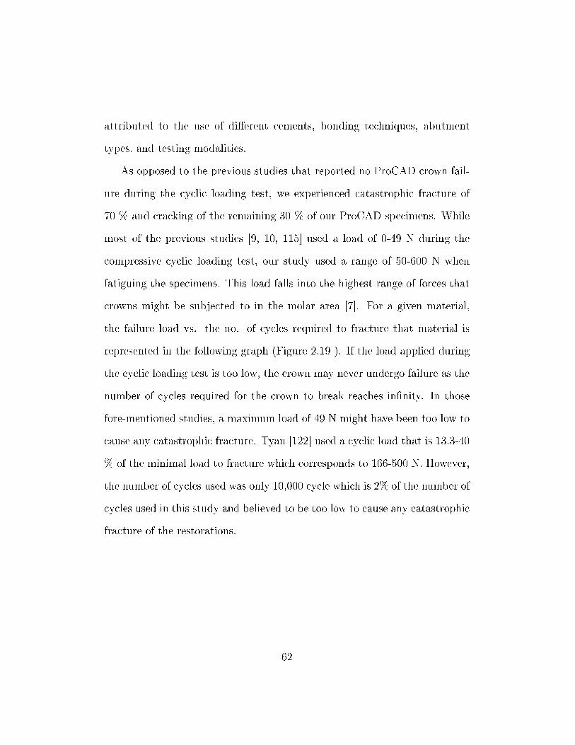
2.19 Number of cycles required for restoration failure graph. . . . . 63
2.20 SEM (500 X) image of milled surface of the Paradigm MZ100
crown showing �ne grooves which is indicative of a plastic
deformation mechanism of material removal. . . . . . . . . . . 66
2.21 SEM (500 X) image of the milled surface of the ceramic crown
showing a fracture mechanism of material removal. . . . . . . 67
2.22 SEM (60 X) comparison between the margin edge of the com-
posite resin vs. the ceramic crown. . . . . . . . . . . . . . . . 67
viii
Chapter 1
Introduction
1.1 Background
The need for esthetic restorations has increased tremendously over the past
decade. Ceramics have gained large popularity as esthetic restorative mate-
rials due to their high esthetic quality [95, 103], wear resistance, durability,
color stability [106], and biocompatibility [112, 4]. However, ceramics have
several disadvantages including low fracture resistance [28], excessive wear
of the opposing teeth [124], the need of more aggressive preparation design
[95, 16], technique sensitivity [16], less than ideal marginal adaptation [9],
repair di�culty [124], and high cost of fabrication. In ceramics, cracks ini-
tiate from defects in the �tted surface of the restoration. Sub-critical crack
growth is facilitated in the aqueous environment of the mouth. [31, 32, 123]
The biocompatibility of all-ceramic restorations [112] has elevated the in-
1
terest in metal-free restorations, especially that metal hypersensitivity has
been a concern to some people. Gold allergy, although rare, had been docu-
mented in the literature [65]. Population prevalence of metal contact allergy
was reported to be 0.78-9.5% for gold [107, 69], 1.6% for silver [63], 9% for
cobalt [69], 8.2% for tin [41], 8% for palladium [63], 8% for chromium [102],
and 29% for nickel [102]. Namikoshi reported a case that developed a hyper-
sensitivity reaction resulting in lichen planus due to the release of palladium
from a dental metal alloy [84]. Contact allergy to metal dental restorations
may even be a risk factor for development of intra-oral squamous cell car-
cinoma [51]. The highest percentage of metal allergic reactions occurred in
patients with lichenoid tissue reactions, lichen planus, burning mouth syn-
drome, stomatitis, gingivitis, and peri-oral dermatitis. [118]
The combination of advancements in dental material, computer technol-
ogy, and equipments has made it possible to fabricate an indirect esthetic
restoration in one appointment. The CAD/CAM CEREC system is used
for electronical designing and milling of restorations. Using this system, the
dentist can manufacture a restoration without the need for lab assistance and
without impressions nor temporary restorations [66]. The restoration can be
designed in less than �ve minutes and then milled in 10 to 12 minutes [119].
Hence, only one appointment is needed to prepare and insert the restoration.
After preparing the tooth, the dentist sprays tin oxide powder on the prepa-
ration. Then, he/she aligns the intra-oral camera's angle of vision for the
scan along the insertion axis of the preparation while checking the image on
2
the monitor. After the camera is stabilized, the preparation is scanned [78]
and the optical impression is completed. The restoration is designed, milled
and polished to prepare it for insertion.
1.2 Porcelain-Fused-to-Metal Restorations
1.2.1 Advantages of Porcelain-Fused-to-Metal Restora-
tions
� Clinically-proven longevity and fracture resistance: fracture rate of
porcelain-fused-to-metal crowns and bridges were reported to be as
low as 2.3% after 7.5 years. [5]
� Combines the esthetics of porcelain with the strength, marginal adap-
tation, and accuracy of cast metal restorations. [103]
� More resistant to fracture than conventional all-ceramic crowns. The
slight di�erence in the coe�cient of thermal expansion between the
metal and ceramic causes the ceramic to undergo residual compressive
stresses following the cooling process during crown fabrication . This
constant residual compressive stresses resists the tensile stresses the
crown is subjected to rendering the crown stronger and more fracture
resistant. [6]
� Amore conservative preparation provides adequate thickness for porcelain-
3
fused-to-metal crowns when compared to all-ceramic crowns. [5]
� No wear of ceramic by abrasion or attrition. [5]
� No change of color due to no microleakage between the veneer and the
metal. [5]
1.2.2 Limitations of Porcelain-Fused-to-Metal Restora-
tions
� Non-ideal esthetics since:
� the metal at the gingival margin may cause gingival discoloration
[131]
� the dark metal core may show through in areas with minimal
porcelain thickness especially at the gingival third
� the metal margin may become visible if gingival recession occurs
� Metal hypersensitivity
1.3 History of the CEREC technology
Advances in computer technology have made it possible to develop the CAD/CAM
technology (Computer-assisted Design/ Computer-aided Manufacturing). The
CEREC system (computer-assisted CERamic REConstruction) was the �rst
operational CAD/CAM system to be used in the dental o�ce [49]. The
4
design was produced by Dr. Brandestini and the software versions were de-
veloped by the CEREC teams at Siemens and Sirona (Bensheim, Germany)
[78]. In 1980, the basic concept was developed by Mormann (University of
Zurich) and Brandestini (Brandestini Instruments, Zurich). Dr. Alain Ferru,
a young French software engineer, was approached by Dr. Mormann to design
the CEREC software. In 1985, the �rst chair-side inlay was fabricated using
the CEREC I by Mormann and Brandestini (Brains, Zurich). In 1988, on-
lays and veneers capabilities were added to the unit. Full and partial crowns
and copings were made possible by introducing the CEREC 2 in 1994 by
Siemens (Munich, Germany). In 2000, the Cerec 3 was introduced and the
three dimensional capability was added in 2003. In 2005, the new software
enabled the automatic virtual occlusal adjustment. [78]
Several studies criticized the marginal �t of the CEREC restorations [121,
106]. However, the improvement in the CEREC unit and software made
it possible to produce more clinically acceptable marginal �t of the milled
restorations. [52, 81, 12, 53, 54, 44, 26]
1.3.1 CEREC I
The CEREC I prototype was available in 1983 [78]. The �rst unit had a
water turbine drive. The modi�ed version with E-drive and CEREC Oper-
ating System 2.0 was launched in 1991. In this system a ceramic block is fed
against a grinding wheel along the mesio-distal axis of the restoration with a
di�erent distance from the inlay axis at each feed step [78]. This system was
5
limited only to inlays, onlays, and veneers [49]. The two dimensional soft-
ware capability did not provide the restoration with any occlusal anatomy or
contact. Hence, the dentist had to carve and �nish the restoration's occlusal
anatomy and contacts him/herself after the unit milled the adapted surface
of the restoration which made this unit impractical to use. [78]
1.3.2 CEREC II
CEREC II was developed in 1994 to try to overcome the limitations of the
CEREC I unit. The team at Siemens (Munich, Germany) added a cylinder
diamond to the system which enabled the CEREC II unit to grind full and
partial crowns and copings [78]. The display was two-dimensional and the
design of the occlusion was introduced in three modes: extrapolation, corre-
lation and function. Bindl and Mormann [15] compared margin adaptation of
Vitablocs Mark II partial crowns fabricated with CEREC-I and CEREC-II
and found signi�cantly improved margin adaptation for CEREC-II manu-
factured partial crowns (207 ± 63µm) compared to those manufactured by
CEREC-I (308± 95µm). Mormann and Schug [82] also compared both sys-
tems in regards to precision of �t of the milled restorations. They found a 30
% improvement in the accuracy �t of CEREC-II manufactured restorations,
with marginal gap of 56±27µm, compared to that of CEREC I, which equals
84± 38µm.
6
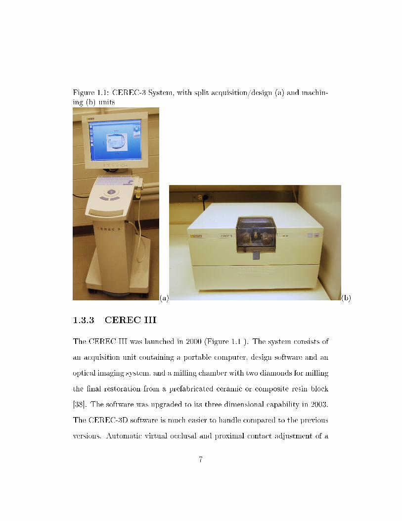
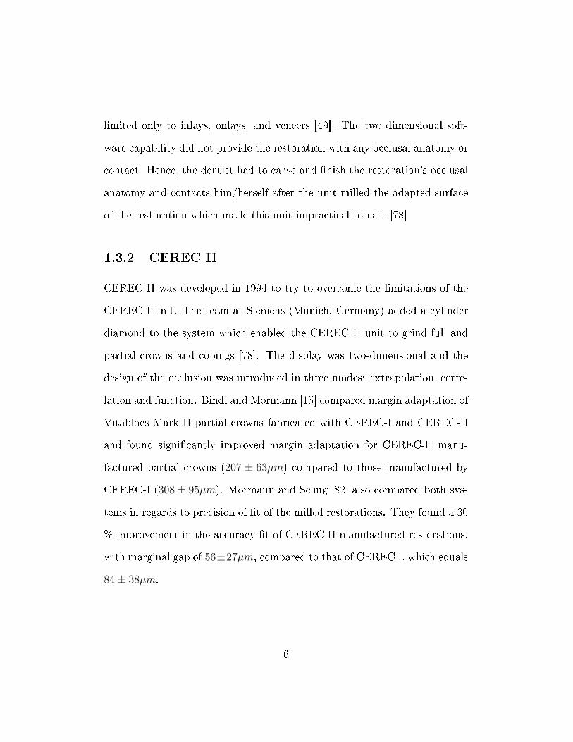
Figure 1.1: CEREC-3 System, with split acquisition/design (a) and machin-ing (b) units
(a) (b)
1.3.3 CEREC III
The CEREC III was launched in 2000 (Figure 1.1 ). The system consists of
an acquisition unit containing a portable computer, design software and an
optical imaging system, and a milling chamber with two diamonds for milling
the �nal restoration from a prefabricated ceramic or composite resin block
[38]. The software was upgraded to its three-dimensional capability in 2003.
The CEREC-3D software is much easier to handle compared to the previous
versions. Automatic virtual occlusal and proximal contact adjustment of a
7
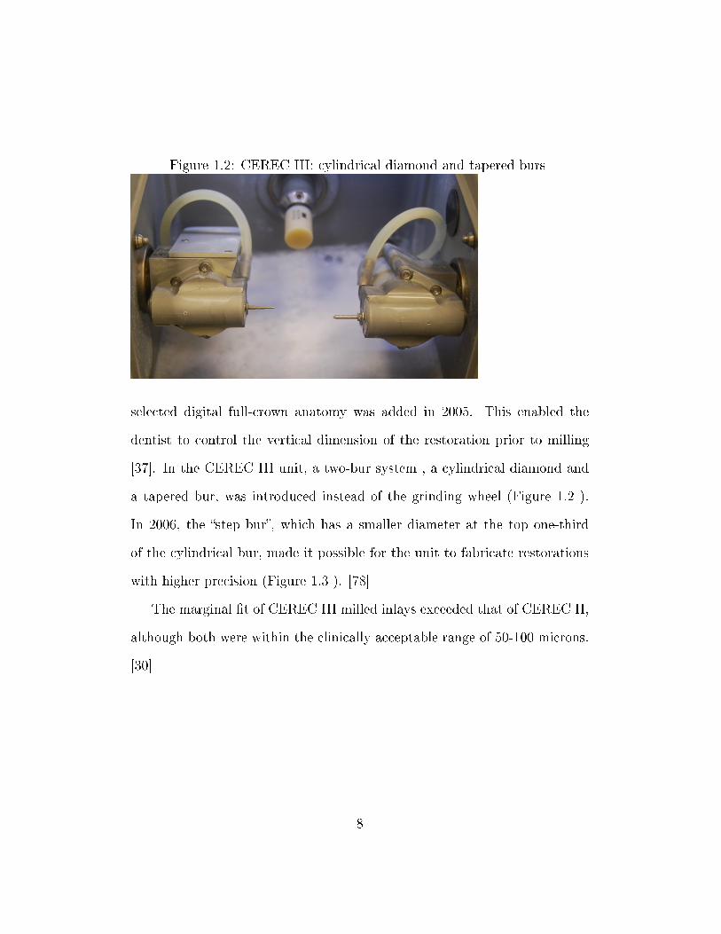
Figure 1.2: CEREC III: cylindrical diamond and tapered burs
selected digital full-crown anatomy was added in 2005. This enabled the
dentist to control the vertical dimension of the restoration prior to milling
[37]. In the CEREC III unit, a two-bur system , a cylindrical diamond and
a tapered bur, was introduced instead of the grinding wheel (Figure 1.2 ).
In 2006, the �step bur�, which has a smaller diameter at the top one-third
of the cylindrical bur, made it possible for the unit to fabricate restorations
with higher precision (Figure 1.3 ). [78]
The marginal �t of CEREC III milled inlays exceeded that of CEREC II,
although both were within the clinically acceptable range of 50-100 microns.
[30]
8
Figure 1.3: CEREC III: in 2006 a �step bur� replaced the cylinder
1.4 Advantages and Limitations of the CEREC
technology
1.4.1 Advantages of the CEREC technology
� CEREC restorations have demonstrated documented clinical success
and longevity [90]. Restoration size, tooth vitality, and tooth location
did not signi�cantly a�ect the prognosis. Posselt and Kerschbaum [90]
reported a survival probability of 95.5% over 9 years.
� The CAD/CAM blocks are fabricated under optimum controlled con-
ditions. This provides a restoration with higher intrinsic strength elim-
inating the material variation found in lab-fabricated restorations. [79]
� Utilizing the CAD/CAM technology, the computer controlled fabrica-
9
tion diminishes the potential inaccuracies resulting from human error
and is able to generate a restoration within a clinically acceptable �t
of about 50 micrometers as established by the American Dental Asso-
ciation. [30]
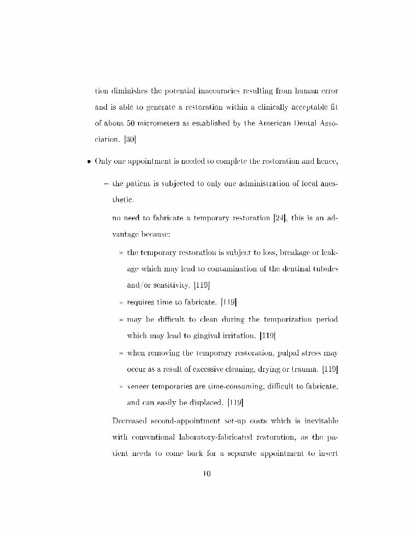
� Only one appointment is needed to complete the restoration and hence,
� the patient is subjected to only one administration of local anes-
thetic.
� no need to fabricate a temporary restoration [24], this is an ad-
vantage because:
* the temporary restoration is subject to loss, breakage or leak-
age which may lead to contamination of the dentinal tubules
and/or sensitivity. [119]
* requires time to fabricate. [119]
* may be di�cult to clean during the temporization period
which may lead to gingival irritation. [119]
* when removing the temporary restoration, pulpal stress may
occur as a result of excessive cleaning, drying or trauma. [119]
* veneer temporaries are time-consuming, di�cult to fabricate,
and can easily be displaced. [119]
� Decreased second-appointment set-up costs which is inevitable
with conventional laboratory-fabricated restoration, as the pa-
tient needs to come back for a separate appointment to insert
10
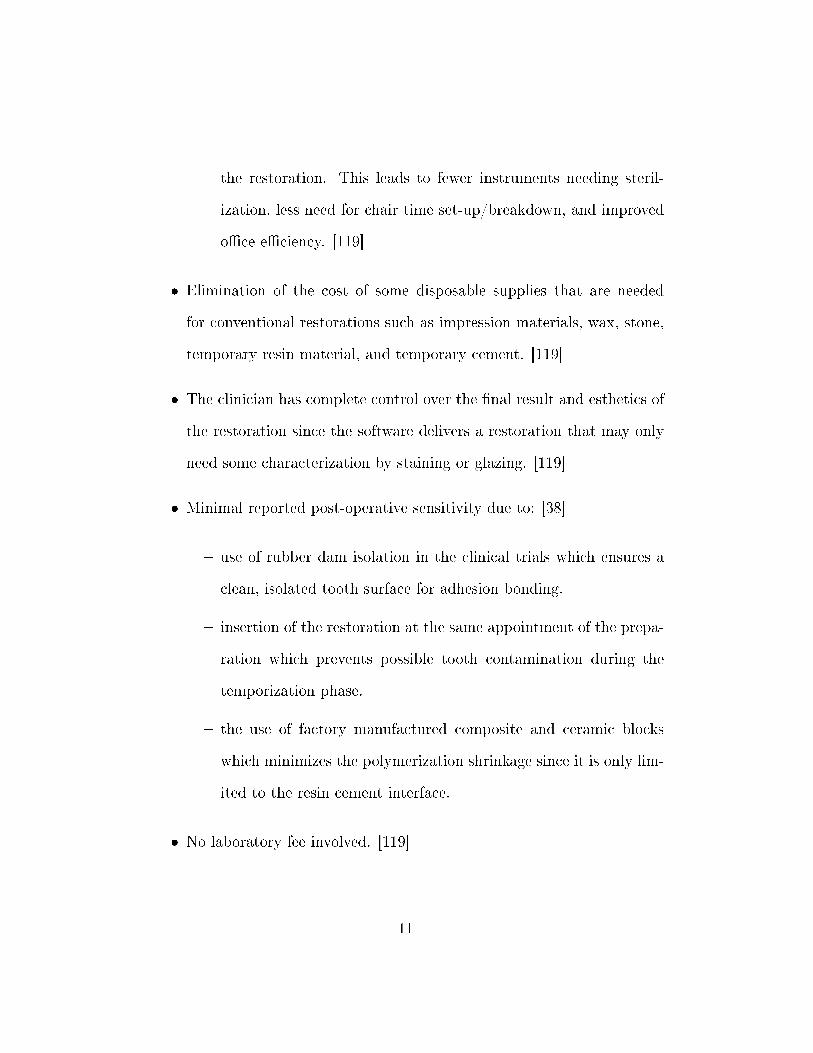
the restoration. This leads to fewer instruments needing steril-
ization, less need for chair time set-up/breakdown, and improved
o�ce e�ciency. [119]
� Elimination of the cost of some disposable supplies that are needed
for conventional restorations such as impression materials, wax, stone,
temporary resin material, and temporary cement. [119]
� The clinician has complete control over the �nal result and esthetics of
the restoration since the software delivers a restoration that may only
need some characterization by staining or glazing. [119]
� Minimal reported post-operative sensitivity due to: [38]
� use of rubber dam isolation in the clinical trials which ensures a
clean, isolated tooth surface for adhesion bonding.
� insertion of the restoration at the same appointment of the prepa-
ration which prevents possible tooth contamination during the
temporization phase.
� the use of factory manufactured composite and ceramic blocks
which minimizes the polymerization shrinkage since it is only lim-
ited to the resin cement interface.
� No laboratory fee involved. [119]
11
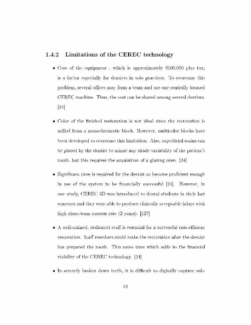
1.4.2 Limitations of the CEREC technology
� Cost of the equipment , which is approximately $100,000 plus tax,
is a factor especially for dentists in solo practices. To overcome this
problem, several o�ces may form a team and use one centrally located
CEREC machine. Thus, the cost can be shared among several dentists.
[24]
� Color of the �nished restoration is not ideal since the restoration is
milled from a monochromatic block. However, multicolor blocks have
been developed to overcome this limitation. Also, super�cial stains can
be placed by the dentist to mimic any shade variability of the patient's
tooth, but this requires the acquisition of a glazing oven. [24]
� Signi�cant time is required for the dentist to become pro�cient enough
in use of the system to be �nancially successful [24]. However, in
one study, CEREC 3D was introduced to dental students in their last
semester and they were able to produce clinically acceptable inlays with
high short-term success rate (2 years). [127]
� A well-trained, dedicated sta� is essential for a successful cost-e�cient
restoration. Sta� members could make the restoration after the dentist
has prepared the tooth. This saves time which adds to the �nancial
viability of the CEREC technology. [24]
� In severely broken down teeth, it is di�cult to digitally capture sub-
12
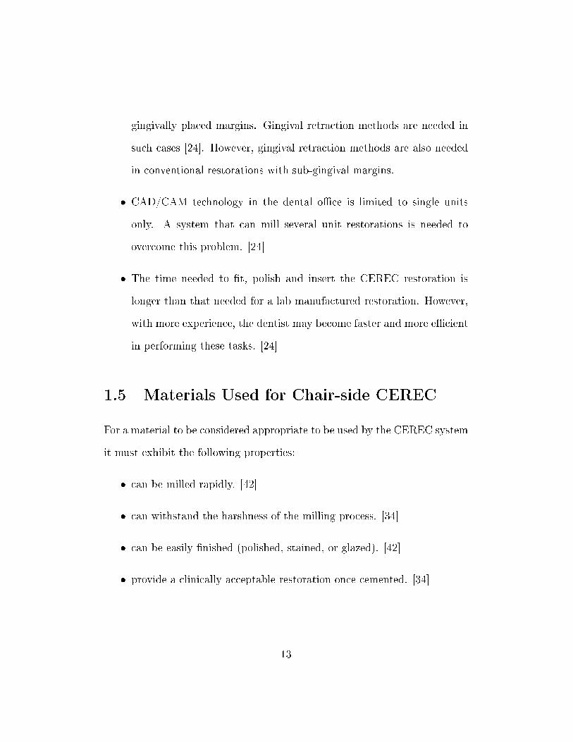
gingivally placed margins. Gingival retraction methods are needed in
such cases [24]. However, gingival retraction methods are also needed
in conventional restorations with sub-gingival margins.
� CAD/CAM technology in the dental o�ce is limited to single units
only. A system that can mill several unit restorations is needed to
overcome this problem. [24]
� The time needed to �t, polish and insert the CEREC restoration is
longer than that needed for a lab manufactured restoration. However,
with more experience, the dentist may become faster and more e�cient
in performing these tasks. [24]
1.5 Materials Used for Chair-side CEREC
For a material to be considered appropriate to be used by the CEREC system
it must exhibit the following properties:
� can be milled rapidly. [42]
� can withstand the harshness of the milling process. [34]
� can be easily �nished (polished, stained, or glazed). [42]
� provide a clinically acceptable restoration once cemented. [34]
13
All CEREC blocks have �ne particle-sized micro-structure which leads to
improved machining damage resistance, faster polishability, improved me-
chanical properties, and decreased wear of the opposing dentition. [42]
1.5.1 Ceramics
Feldspathic porcelain-based ceramics:
� Vitablocs Mark II (Vita Zahnfabrik, Bad Sackingen, Germany):
� Introduced in 1991. [34]
� Is a �ne-grained feldspathic ceramic [34] manufactured using �ne-
grained powders producing �ne crystal, pore-free ceramic which
leads to better polishability, lower enamel wear and higher strength
[42]. The strength of this ceramic material when polished is
approximately 130 MPa and it could reach 160 MPa or higher
if glazed. This is about twice as strong as conventional felds-
pathic ceramics and slightly higher than many pressable ceramics.
[101, 43]
� The average particle size is approximately 4µm. [34]
� It can be etched using hydro�uoric acid or abraded with Alu-
minum Oxide particles creating a retentive surface that provides
micro-mechanical retention to the adhesive resin cement. [34]
� CEREC Blocs (Vita Zahnfabrik, Bad Sackingen, Germany).
14
Leucite-reinforced Ceramics:
� ProCAD (Ivoclar Vivadent, Schaan, Lichtenstein) blocks:
� Introduced in 1998. [34]
� They can be etched. [34]
� A leucite-reinforced ceramic [34] with leucite crystals ranging from
5 to 10 micrometers in size. Strength properties are similar to
those of Vitablocs Mark II. [42]
� Empress CAD (Ivoclar Vivadent, Schaan, Lichtestein) blocks:
� The new generation of ProCAD
Advantages of Ceramics
� It is possible to produce a ceramic restoration with natural appearance
[9] in terms of color, translucency, and surface texture [95, 104] due to
the wide range of shades and translucency - opacity combinations that
can be customized to each case. The surface can also be characterized
by add-on stains for improved shade match to the adjacent tooth. [42]
� Ceramics are inert and highly biocompatible [109, 112] due to their
glass-like properties. Dental plaque adherence is minimized when the
ceramic restoration is polished and glazed [59]. A supra-gingival or
at-the-gingiva margin can produce an esthetically pleasing result with
15
all-ceramic restorations. This promotes a healthy periodontium since
,with these margins, the gingival involvement during tooth preparation,
impression, and function is minimized. [59]
� Machined ceramics demonstrated less wear rate when compared to type
I gold alloys, base-metal alloys, cobalt chromium alloys and composite
resin. [128]
� Ceramics have also shown better color stability compared to composite
resin restorations. [106]
Disadvantages of Ceramics
� Low tensile strength. [75]
� Higher yield stress response than enamel. [47]
� Crack propagation that may lead to catastrophic fracture [9]. Cracks
may initiate from two types of defects: fabrication defects (which are
introduced during processing or that exist as micro-structural features)
or surface micro-cracks (which are introduced during the machining
stage) [96]. The interaction of applied loads with those defects may
lead to microscopic damage which may cause restoration failure [28].
Failure can also occur as a result of sub-critical crack growth [31, 32]
which is facilitated by the surrounding aqueous environment.
� Excessive brittleness. [75, 98]
16
� Di�cult to repair if fracture occurs. [23, 98]
� Di�cult to adjust chair-side. [98]
� Technique sensitivity.
� Require �ring for glazing and stain characterization [98]. Glazing is
required for ceramics to attain optimum strength. [98]
� Firing shrinkage. [73]
� Wear of opposing natural dentition. [124, 98]
� Inadequate marginal �t which may lead to microleakage [9]. New ce-
ramic formulations and processing techniques were developed to over-
come such limitation. Also, the improvement of bonding systems and
the use of computed technology have resulted in all-ceramic restorations
with improved marginal adaptation and decreased microleakage. The
use of resin cement with ceramic restorations demonstrated improved
marginal �t and decreased microleakage. [97]
However, dental ceramics have been improved over the past two decades to
overcome the fore-mentioned limitations. Among these improved ceramics
is the injection molded Empress glass ceramic (Vivadent, Schaan, Liechten-
stein), a leucite-reinforced material that has improved fracture resistance.
17
1.5.2 Composite Resin
� Paradigm MZ100 (3M ESPE, St. Paul, Minn.)
� First introduced to the market in 2000. [34]
� ParadigmMZ100 is a bisphenol A-diglycidyldimethacrylate/triethylene
glycol dimethacrylate resin-based composite with �ller composed
of nanocrystalline zirconia in an amorphous silica matrix [98]. The
inorganic �ller is radio-opaque and its loading is 85% by weight
with mean particle size of 0.6 micrometers. Paradigm MZ100 is a
factory processed version of Z100 Restorative (3M ESPE) resin. It
has superior physical properties comparing to conventional Z100
resin due to controlled manufacturing conditions which lead to
a dense, pore-free material that is completely cured throughout.
This processing technique maximizes the degree of cross-linking
[34]. The degree of conversion of the methacrylate groups in
the Paradigm MZ100 is approximately 84% which is higher than
that for Z100 direct restorative composite resin material (74%).
This provides both dependable physical properties and su�cient
amount of unreacted monomers for bonding. [98]
Advantages of Composite Resin
� According to the manufacturers, a more conservative chamfer or bevel
preparation is acceptable with resin compared to ceramics which require
18
a shoulder or a broad chamfer. [121]
� Easier �nishing and polishing than ceramics. [42]
� Can be easily adjusted and/or polished intra-orally. [34]
� Kinder to opposing teeth in regards to wear relative to ceramics. [42,
98]
� Easier to add on adjustments if necessary which is di�cult in ceramic
restorations [132]. The surface can be air-abraded using 50µm silicon
dioxide particles then bonded to hybrid resin. [34]
� Color characterization can be easily accomplished by internal or exter-
nal resin tints and color modi�ers, which are light-cured rather than
oven-�red. [34]
� Using Paradigm MZ100 blocks can elongate the life of the milling di-
amond and increase the number of composite resin restorations milled
by each milling diamond before requiring replacement [34]. Rusin et al
[99] observed that ceramic materials required milling diamond replace-
ment at signi�cantly earlier stage than the Paradigm MZ100 material.
This leads to reduced operating cost and fewer delays from diamond
bur exchange. [99]
19
1.6 Concerns of the current CEREC materials
1.6.1 Strength
The blocks used for CEREC are fabricated under ideal manufacturing con-
ditions in a reproducible constant manner eliminating human error. This
results in a dense, defect-free, high-quality material. On the other hand,
conventionally fabricated restorations are made by hand which may intro-
duce human error that could a�ect its mechanical and esthetic properties.
[42]
In one study [117], it was concluded that industrially prepared ceramics
are more structurally reliable than conventional lab-fabricated ceramics al-
though CAD-CAM procedures may introduce surface and subsurface �aws
that may adversely a�ect this property. However, the strength can be gained
back by polishing using rubber wheels and diamond paste. Further enhance-
ment of strength of about 160 MPa can be acquired using a combination of
polishing and glazing. [42]
Attia concluded that the fracture resistance of teeth restored with CEREC
manufactured crowns was equivalent to that of unprepared natural teeth, but
was signi�cantly higher than that of teeth restored by conventional low-fusing
ceramic crowns. [9]
20
1.6.2 Esthetics
Esthetics have been a concern in CEREC materials due to the monochro-
matic nature of the blocks. However, the porcelain restoration can be stained
and glazed after milling. Color modi�ers and internal and external tints can
be easily added to composite restorations then cured [34]. Also, the blocks
come in a large variety of shades to match the adjacent natural dentition.
Vitablocs TriLuxe (Vita Zahnfabrik) contain three shades in a graded vari-
ation in which the middle layer has a regular chroma, the top layer has a
translucent, low intense chroma, and the lower layer has low translucency
and an intense chroma. This makes it possible to imitate the optical charac-
teristics of the natural tooth and hence make the restoration more blendable
with the adjacent teeth. [42]
Herrguth et al. conducted a clinical study to compare the esthetics of
individually stained CEREC-manufactured crowns to Cergogold crowns (De-
gussa Dental GmbH, Hanau, Germany) which is fabricated by the layering
technique [48]. They concluded that regardless of the type of crown used, the
restorations were esthetically acceptable to all patients with no statistically
signi�cant di�erence in the esthetic ratings between the two crowns. In a
clinical study of 109 inlays in 46 patients over 7 years, Cerutti et al. [21]
reported an initial good shade match of 88 % Alfa which decreased to 62.4 %
Alfa and 33 % Bravo after 7 years. Several studies reported that the degree
of color mismatch increased over time [76, 39]. In a series of studies by Sjo-
gren et al. [108, 110, 111] of 66 Vitablocs Mark II inlays, the color mismatch
21
increased from 16% to 38% after 10 years. The observed increase in color
mismatch was due to a color change of the tooth rather than the color shift
of the milled restoration [39]. In a di�erent clinical study, Fasbinder et al.
reported that the color match of Paradigm composite inlays was signi�cantly
better than Vitablocs Mark II ceramic inlays at three years. This was due to
the fact that composite resin appeared to re�ect the surrounding tooth color
to a better degree than did the ceramic inlays. [38]
In conclusion, CEREC-manufactured restorations can provide an esthet-
ically acceptable restoration when polished and an esthetically optimum one
when stained and glazed. The decrease in color match over time can be at-
tributed to a change in tooth shade and translucency, rather than a change
in the color of the CEREC-manufactured restoration. [36]
1.6.3 Post-operative Sensitivity
Signi�cant level of post-operative sensitivity was reported in early clinical
studies addressing CEREC-manufactured restorations. Magnuson et al. [67]
reported 9% immediate post-operative sensitivity in a study of 301 CEREC-
manufactured inlays. Most of these cases involving post-operative sensitivity
resolved within one month. However, three cases remained problematic for
six months and which necessitated endodontic therapy. In a di�erent study
by Sjogren et al. [108], 13.8 % of patients with Vitablocs Mark I or II inlays
complained of post-operative hypersensitivity. In a three-year clinical study
by Fasbinder et al. [40], 13 % of 92 Vitablocs Mark II onlays were slightly
22
sensitive after one week, and 4 % were slightly sensitive in two weeks. All
post-operative sensitivity resolved after one month, and no post-operative
sensitivity was reported in the three-year period of observation. Otto and
De Nisco [87] observed 13 % immediate post-operative sensitivity in 200
CEREC-manufactured inlays that were caused by premature occlusal con-
tact. Out of the 17 cases reported, 12 resolved within three weeks and the
rest resolved in seven months. The majority of post-operative sensitivity
can be attributed to occlusal interference since the CEREC-manufactured
restorations are inserted in a single appointment. Hence, it is advisable to
equilibrate the occlusal contacts after the e�ects of the local anesthetic have
worn away. [36]
More recent studies have reported less post operative sensitivity which
could be attributed to the signi�cant improvement of the adhesive materials.
In a study of 20 CEREC- generated Vitablocs Mark I inlays, Molin and
Karlsson reported no post-operative sensitivity throughout the observation
period of 5 years [76]. The same results were observed by Heymann et al. in
their four-year clinical trial of �fty CEREC-generated inlays [49]. Fasbinder
et al. reported only one sensitive restoration at one week in their randomized
clinical trial of 80 Vitablocs Mark II and Paradigm inlays. However, it was
resolved in two weeks and no sensitivity was reported in the remainder of the
observation period of three years. [38]
The lack of signi�cant post-operative sensitivity in CEREC-manufactured
restorations can be attributed to several factors. The optical imaging of the
23
preparation requires careful isolation. This ensures that optimum �uid con-
trol is possible which maximizes the adhesive cementation predictability [36].
The fact that CEREC-manufactured restorations eliminate the need of tem-
porization contributes to the lack of post-operative sensitivity, as it prevents
the possible contamination of the dentin tubules during the temporization
period if the temporary restoration is lost, fractured, or leaked. [38]
1.6.4 Margin Adaptation
Nakamura et al. [83] studied the e�ect of abutment occlusal conversion angle
and the computer luting space setting on the internal �t and marginal adap-
tation of the ceramic CEREC III milled restoration. They found that when
the computer luting space was set to 30 to 50 micrometers, the marginal gap
ranged from 53 to 67 micrometers and was not in�uenced by the abutment
angle of occlusal conversion. Other researchers measured margins of about
50 micrometers [30, 91] which suggested that the marginal �t of CAD/CAM
generated restorations is adequate for clinical use. Denissen et al. [26] re-
ported a margin gap of 85µm for CEREC III manufactured onlays, this is not
signi�cantly di�erent from that of the laboratory-fabricated onlays. These
recorded gaps are well within the reported maximum clinically accepted gap
of 120 µm. [74]
In a study of CEREC-manufactured restorations, Fasbinder reported less
detectable margins in resin-based composite inlays (Paradigm) compared to
ceramic inlays (Vitablocs Mark II) after 1 year [38]. However, in 3 years, no
24
signi�cant di�erence in margin adaptation between the ceramic and resin-
based composite inlays was detected. The nature of the tooth antagonist to
the restoration did not a�ect the amount of margin ditching [11]. Posselt
and Kerschbaum [90] reported 47.4 % of under�lled margins of 44 CEREC I
and CEREC II-manufactured restorations after 9 years.
A well-�tting margin is expected to maximize the longevity of a restora-
tion. In almost all the clinical studies of CEREC-manufactured restorations,
ditching due to wear of the composite resin cement at the margin was re-
ported. However, this ditching was not associated with margin discoloration
or recurrent decay. In a clinical study of 121 Vitablocs Mark II and Dicor
inlays cemented with micro�ll or hybrid resin-based composite luting agent,
a linear wear rate was reported in the �rst year but then it decreased by
approximately 50% [54]. They found that the vertical loss of cement at the
margin stopped when it reached 50% of the margin width. No microleak-
age or secondary decay was reported at the margin. Heymann et al. [49]
reported an increase in the wear of the adhesive luting agent at the occlusal
margin of inlays over the �rst 3 years, and then a decrease of that wear after
3 years. No enamel or porcelain inlay margin chipping or margin staining
was identi�ed as the adhesive cement started to wear. In a study compar-
ing Vitablocs Mark I and Dicor MGC porcelain inlays and P-50 resin-based
composite inlays, no signi�cant di�erence in margin adaptation was reported
[44]. No marginal staining or recurrent decay was noted either. In Otto and
De Nisco's study [87], a 74% occurrence of under�lled margins after 10 years
25
was not associated with clinical failure.
These studies agree to the fact that the margin wear is just a surface
phenomenon that is not associated with a deterioration in the adhesive bond
to the tooth. Also, the wear tends to localize at the margin of the occlusal
surface of the restoration rather than the margins of the proximal surfaces.
Micro�ll resin cements demonstrated better wear pattern compared to hybrid
resin cements. [57, 133]
1.6.5 Enamel Wear
Enamel wear is always a concern when ceramics are used as a restorative ma-
terial. Several factors may in�uence the harshness of ceramics against enamel
tooth structure. It is possible to minimize enamel wear by using �ne-grained
ceramics and by polishing or glazing the ceramic surface [42]. Several studies
have demonstrated that the wear of enamel against polished or glazed ceramic
restorations was essentially the same of that against enamel [61, 72, 71, 1].
Researchers measured the amount of tooth structure lost when in function
with di�erent dental materials and normalized the data relative to enamel
versus enamel. They found that Vitablocs Mark II and ProCAD blocks be-
haved much like enamel, whereas Paradigm MZ100 exhibited slightly higher
resin material loss, i,e. gentler on enamel than porcelains. [42]
26
1.6.6 Longevity
CEREC manufactured restorations have proven their success and longevity
through several studies. The �rst clinical trial was conducted by Mormann
et al. [80] who evaluated 94 CEREC I -manufactured Vitablocs Mark I in-
lays between September 1985 and August 1987 and reported two fractured
inlays. This low level of failure was repeatedly reproduced by a large number
of clinical studies. Isenberg et al. [54] observed 121 CEREC I -generated
inlays and reported a 94.2% success rate over three years. All the fractures
of the failed restorations (3 out of 121 inlays) occurred through the occlusal
isthmus and the thickness of ceramic at fracture site was less than 2 millime-
ters. In a clinical study over a 5-year period, Berg and Derand [11] reported
3 fractures in 115 Vitablocs Mark I inlays. A systemic review by Martin
and Jedynakiewicz undertook a comprehensive literature search from 1986
to 1997 to identify the survival rate of such restorations and their causes of
failure [70]. It determined that the mean survival rate of CEREC manufac-
tured restorations was 97.4% over a period of 4.2 years. Causes of failure
included fracture of ceramic, fracture of supporting tooth, post-operative
sensitivity, and wear of the adhesive. Vitablocs Mark II was used in most
of these clinical studies but ProCAD was used occasionally. Mormann and
Schug studied only Vitablocs Mark II and concluded that the success rate
was 95% in 5 years [82]. Brauner and Bieniek [18] reported a survival rate
of 88% for 238 Vitablocs Mark II inlays after 5.5 years of clinical service of
inlays. In a di�erent study, only one Vitabloc Mark II inlay fractured out
27
of 16 pairs of CAD/CAM inlays during an eight-year period [88]. During
the recall period, no tooth fractures were observed. A 90.4% survival rate
for 200 Vitabloc Mark II inlays was observed by Otto and De Nisco after
10 years of clinical service of inlays [87]. The failure was caused by ceramic
fractures in 8 cases and by tooth fracture in 3 cases. In an in-vivo study,
18 anterior Vitablocs Mark II crowns were compared to 18 anterior Ceramic
core (In-Ceram Spinell) crowns. Survival rate was determined to be 91.7%
for In-Ceram Spinell and 94.4% for Vitablocs Mark II over 2-5 years without
a statistically signi�cant di�erence [14]. This raised the interest in evalu-
ating monoceramic Vitablocs Mark II crowns clinically as an alternative to
ceramic-core crowns. Bindl et al. compared Vitablocs Mark II crowns in
regards to type of preparation and tooth type. They classi�ed type of prepa-
ration design to classic crown preparation (preparation wall height of at least
3 mm, 6-8 degree taper, and 1-1.2 mm shoulder), reduced crown preparation
(preparation wall height less than 3 mm), and endodontic crown preparation
(no clinical crown remaining which used only the pulp chamber for reten-
tion). In molars, the survival probability was 94.6% in classic crowns, 92.1
% in reduced crown, and 87.1 % in endodontic crowns. In premolars, the
reported survival probability was 97 % in classic crowns, 92.9 % in reduced
crown, and 68.8 % in endodontic crowns. A signi�cant di�erence was found
between the premolar classic crown and endodontic crown. The success of
the reduced crown was attributed to the use of the adhesive resin. They
concluded that CEREC-manufactured restorations had good prognosis for
28
classic and reduced crowns on both molars and premolars, and endodontic
crowns only for molars.
Another study evaluated 2,328 CEREC fabricated ceramic inlays and on-
lays in 794 patients and the survival rate was found to be 95.5% at 9 years
[90]. The majority of failure was caused by inlay fracture, tooth fracture,
tooth extraction, and replacement for occlusal reconstruction. In this study,
a successful prognosis was not a�ected by restoration size, tooth vitality,
treatment of caries profunda (CP), type of tooth treated, or whether the
restoration was placed in the maxilla or mandible. Reiss and Walther pub-
lished a series of articles on 1,011 CEREC-manufactured inlays and onlays
placed between 1987 and 1990 in 299 patients and evaluated them for up
to 18 years. They determined a survival probability of 95% after 5 years,
91.6% after 7 years, and 90.0% at 10 years [93, 94, 92]. Prognosis for inlays
in premolars (90%) was more favorable than those in molars (80 %). The lo-
cation of the restoration (maxillary or mandibular) and the number of tooth
surfaces restored did not signi�cantly in�uence the survivability of the inlay.
Sjogren et al. [108, 110, 111] published 3 reports on 66 Vitablocs Mark II
inlays from 1995 to 2004 and determined a survival probability of 89% after
10 years.
This survival rate is comparable to that of conventional IPS-Empress ce-
ramic restorations which was reported in a literature review to range from
96% at 4.5 years to 91% at 7 years for inlays and onlay and to range from
92% to 99% at 3-3.5 years for crowns [29]. In a separate literature review by
29
Hickel and Manhart, annual failure rates in posterior stress-bearing restora-
tions were reported to be: 0-7% for amalgam restorations, 0-9% for direct
composites, 1.4-14.4% for glass ionomers and derivatives, 0-11.8% for com-
posite inlays, 0-7.5% for ceramic restorations, 0-5.9% for cast gold inlays and
onlays, and 0-4.4% for CAD/CAM ceramic restorations [50]. While recurrent
decay was the primary cause of failure in direct restorations, fracture of the
restoration and tooth fracture were the the most frequent causes of failure in
indirect restorations.
In a clinical study, resin-based composite CAD/CAM inlays performed as
good as porcelain CAD/CAM inlays after three years of clinical observation
[38]. Fasbinder et al. also concluded that porcelain fracture was the primary
cause of failure for Vitablocs Mark II inlays, as two of the 40 Vitablocs Mark
II inlays and none of the Paradigm inlays fractured over the three year period
of study.
A low failure rate of CEREC-manufactured restorations was consistently
reported in the literature. This documents the reliability and the clinical
predictability of such restorations. Similar to conventional ceramic restora-
tions, the primary cause of failure of CEREC-manufactured restorations is
ceramic and tooth fractures. [50]
30
1.7 E�ects of porcelain surface pre-treatment
and luting cement on bond strength
Di�erent treatments of the adapted surface of the ceramic have been devel-
oped to improve the bonding strength to the resin luting cement [55, 77].
This includes mechanical roughening of the ceramic adapted surface with
a coarse diamond bur [2], air abrasion using Alumina particles [126], and
etching with hydro�uoric acid [114]. Each technique has some limitations.
Mechanical roughening could cause ceramic to chip which may a�ect the �t
of the restoration. Hydro�uoric acid is toxic, caustic, and extremely irritable
to the skin and lungs. [55]
Following the micro-roughening of the ceramic surface, a silane coupling
agent is applied which has bi-functional molecules capable of reacting with
both porcelain surface at one end and the resin luting cement at the other
end forming a chemical bond [33]. The use of this method has yielded a high
fracture resistance comparable to that of porcelain-fused to metal restora-
tions [27, 116, 55, 129, 56]. The fracture resistance is also a�ected by the
fabrication technique, the restoration's �nal surface �nish, and the type of
luting cement used [22, 58]. Chen et al. [22] concluded that oven-glazing
of ProCAD crowns resulted in signi�cantly higher strength and higher resis-
tance to cyclic loading than surface polishing.
Resin-based composites are the material of choice for adhesive luting for
all-porcelain restorations. Physical properties and wear behavior of �ne par-
31
ticle hybrid-type resin-based composites exceed those of other materials [62].
Enamel and dentin bonding was proven clinically acceptable when utilize
multi-step systems with separate primer and bonding agents, as it provides
a perfect internal seal with almost no hypersensitivity. [62]
32
Chapter 2
The Project
2.1 Rationale, Objectives and Hypothesis
2.1.1 Rationale
The demand for esthetic restorations has increased dramatically over the past
2 decades. The development of CAD/CAM technology has made it possible
to fabricate an indirect restoration at one appointment while the patient is
waiting. Several machinable materials are currently available to be used for
the CEREC chair-side restoration manufacturing. The recent introduction of
the composite resin blocks to be used for crowns has raised the question for
their strength and durability compared to ceramic blocks. The majority of
published CAD/CAM-manufactured restorations long-term clinical studies
were based on the CEREC I system. Hence, most of them addressed ceramic
inlays and onlays only and very few more recent studies focused on crowns
33
[36]. As a result, CEREC manufactured ceramic restorations were heavily
studied and their long term failure rate was reported to be low [68, 92, 111,
87, 88]. However, studies addressing CEREC manufactured composite resin
restorations are very limited. Hence, it is crucial to test the mechanical
properties such as fracture strength and fatigue resistance of these materials
in-vitro prior to conducting costly in-vivo studies.
Although laboratory studies are valuable to test the physical and mechan-
ical properties of the dental material, clinical studies are still mandatory to
test the clinical performance of the restoration in its actual setting in the
oral environment under normal function.
2.1.2 Objectives
The objectives of this study were:
1. To measure and compare fracture strength of crowns made with two dif-
ferent materials (ProCAD and Paradigm MZ100) utilizing CAD/CAM
CEREC-3D technology.
2. To investigate the e�ects of mechanical cyclic loading on the fatigue
resistance and fracture strength of CAD/CAM manufactured ceramic
(ProCAD) and composite resin (Paradigm MZ100) crowns.
2.1.3 Hypothesis
The null hypotheses are:
34
1. There is no di�erence between the fracture strength of CEREC manu-
factured ceramic and composite resin crowns.
2. Cyclic loading has no e�ect on fracture strength of crowns made with
the two di�erent materials (ceramic and composite resin).
3. There is no di�erence in fatigue resistance between CEREC manufac-
tured ceramic and composite resin crowns.
2.2 Materials and Methods
2.2.1 Sample Size Calculation
Using the following formula [86], the sample size was calculated at (α = 0.05)
and (β = 0.1):
n = 2[(Zα + Zβ)δ/∆]2
where:
n =sample size per group
Zα =standard score (Z value) corresponding to alpha error
Zβ =standard score (Z value) corresponding to beta error
δ =common standard deviation for both populations
∆ =di�erence in the mean that is considered to be clinically signi�cant
The values used for sample size calculation were based on a similar previ-
ous study [130] where the mean fracture strength of Vitabloc Mark II crowns
35
was 1272.65±109.06. A di�erence of 15% was set arbitrary for the di�erence
in mean between the samples to be considered clinically signi�cant.
n = 2[(1.96 + 1.28)[(109.06/1.15(1272.65) − 1272.65]2 = 6.85 (7 samples
per group)
Several studies comparing fracture strength of di�erent materials used a
sample size of 8-10 per group [130, 10, 9]. Hence, we selected n = 10 for the
sample size of our study.
2.2.2 Preparation
An arti�cial ivorine mandibular molar replica was prepared to receive an all-
ceramic crown following the preparation guidelines suggested for the CEREC
3D system [35]. The tooth received a reduction of 2 mm of the functional
cusp and 1.5 mm of the non-functional cusp. Minimal axial reduction was
1.2 mm and the gingival margin was a circumferential shoulder of at least 1
mm width. The lingual and facial surfaces were prepared in two planes and
all line angles were rounded to decrease stress concentration. The angle of
convergence was 12o. The prepared tooth replica was duplicated to form 40
replicas fabricated from highly �lled epoxy resin material (Viade Products
Inc., Camarillo, California, USA) (Figure 2.1 ). This material has a modulus
of elasticity equivalent to that of human dentin (12.9 GPa) and responds to
34% phosphoric acid etching by forming micro-roughness for bonding [85].
Using a caliper, the replicas' dimensions were measured occluso-gingivally,
facio-lingually, and mesio-distally to verify accuracy of reproduction (Table
36
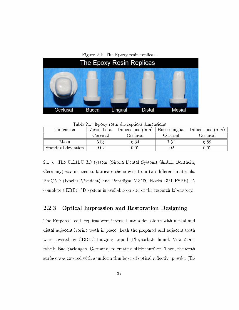
Figure 2.1: The Epoxy resin replicas.
Table 2.1: Epoxy resin die replicas dimensionsDimension Mesio-distal Dimensions (mm) Bucco-lingual Dimensions (mm)
Cervical Occlusal Cervical Occlusal
Mean 6.88 6.34 7.51 6.89Standard deviation 0.02 0.01 .02 0.01
2.1 ). The CEREC 3D system (Sirona Dental Systems GmbH, Benshein,
Germany) was utilized to fabricate the crowns from two di�erent materials:
ProCAD (Ivoclar/Vivadent) and Paradigm MZ100 blocks (3M/ESPE). A
complete CEREC 3D system is available on site of the research laboratory.
2.2.3 Optical Impression and Restoration Designing
The Prepared teeth replicas were inserted into a dentoform with mesial and
distal adjacent ivorine teeth in place. Both the prepared and adjacent teeth
were covered by CEREC Imaging Liquid (Ploysorbate liquid; Vita Zahn-
fabrik, Bad Sackingen, Germany) to create a sticky surface. Then, the teeth
surface was covered with a uniform thin layer of optical re�ective powder (Ti-
37
tanium dioxide; Vita Zahnfabrik, Bad Sackingen, Germany). The CEREC
3D intra-oral camera was used to capture optical impressions of the pre-
pared teeth replicas. An arti�cial ivorine unprepared mandibular molar was
inserted in a dentoform with adjacent teeth and a preoperative occlusal im-
pression was captured. CEREC 3D (Serial number 04996) and CEREC 3D
software V3.10 (Sirona Dental Systems GmbH, Bensheim, Germany) were
used to design the crown utilizing the correlation mode and the crown cop-
ings.
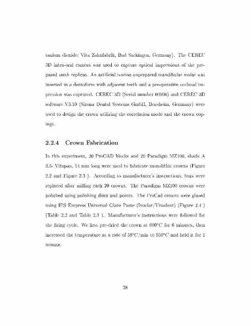
2.2.4 Crown Fabrication
In this experiment, 20 ProCAD blocks and 20 Paradigm MZ100, shade A
3.5- Vitapan, 14 mm long were used to fabricate monolithic crowns (Figure
2.2 and Figure 2.3 ). According to manufacturer's instructions, burs were
replaced after milling each 20 crowns. The Paradigm MZ100 crowns were
polished using polishing discs and points. The ProCad crowns were glazed
using IPS Empress Universal Glaze Paste (Ivoclar/Vivadent) (Figure 2.4 )
(Table 2.2 and Table 2.3 ). Manufacturer's instructions were followed for
the �ring cycle. We �rst pre-dried the crown at 600oC for 6 minutes, then
increased the temperature at a rate of 58oC/min to 950oC and held it for 1
minute.
38
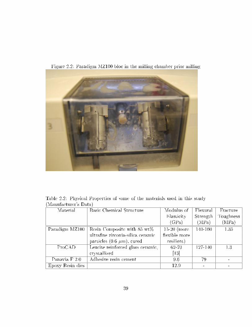
Figure 2.2: Paradigm MZ100 bloc in the milling chamber prior milling
Table 2.2: Physical Properties of some of the materials used in this study(Manufacturer's Data)
Material Basic Chemical Structure Modulus of Flexural FractureElasticity Strength Toughness(GPa) (MPa) (MPa)
Paradigm MZ100 Resin Composite with 85 wt% 15-20 (more 140-160 1.35ultra�ne zirconia-silica ceramic �exible moreparticles (0.6 µm), cured resilient)
ProCAD Leucite reinforced glass ceramic, 62-70 127-140 1.3crystallized [13]
Panavia F 2.0 Adhesive resin cement 9.6 79 -Epoxy Resin dies 12.9 - -
39
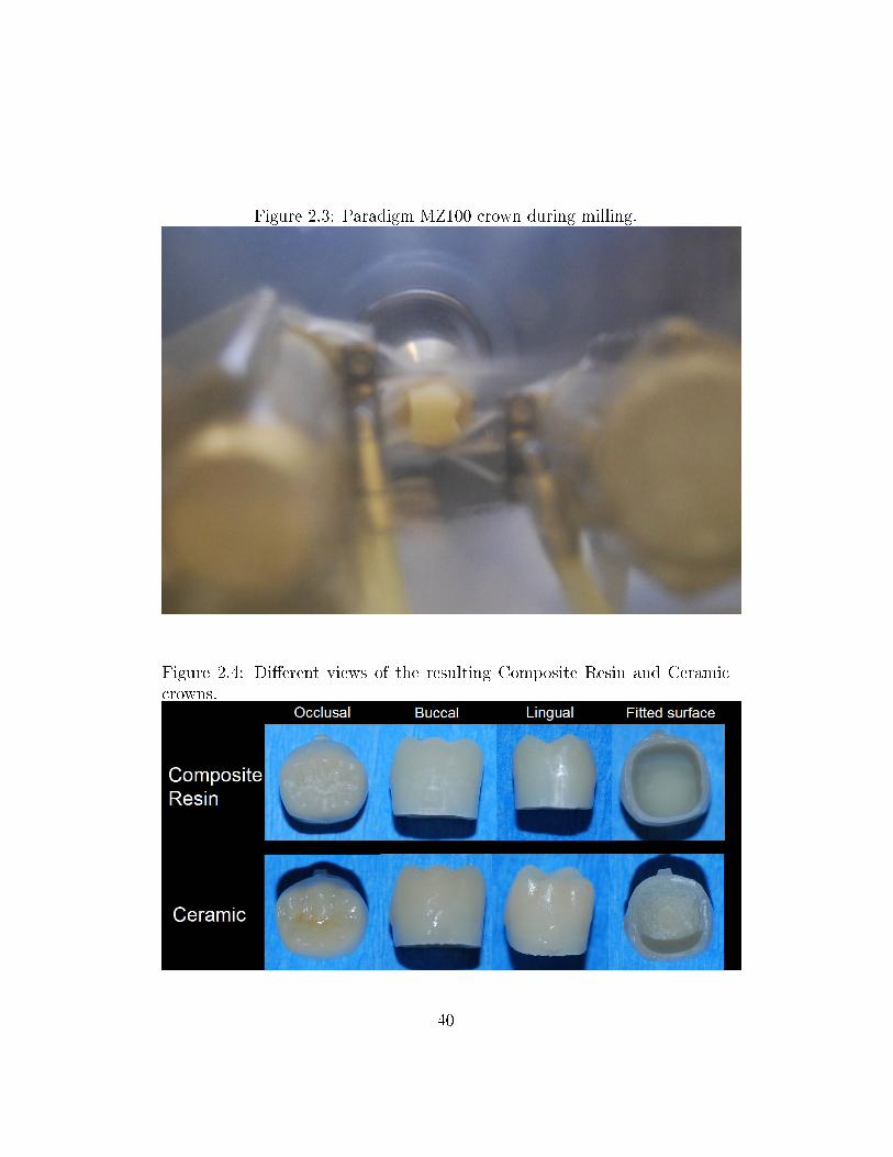
Figure 2.3: Paradigm MZ100 crown during milling.
Figure 2.4: Di�erent views of the resulting Composite Resin and Ceramiccrowns.
40
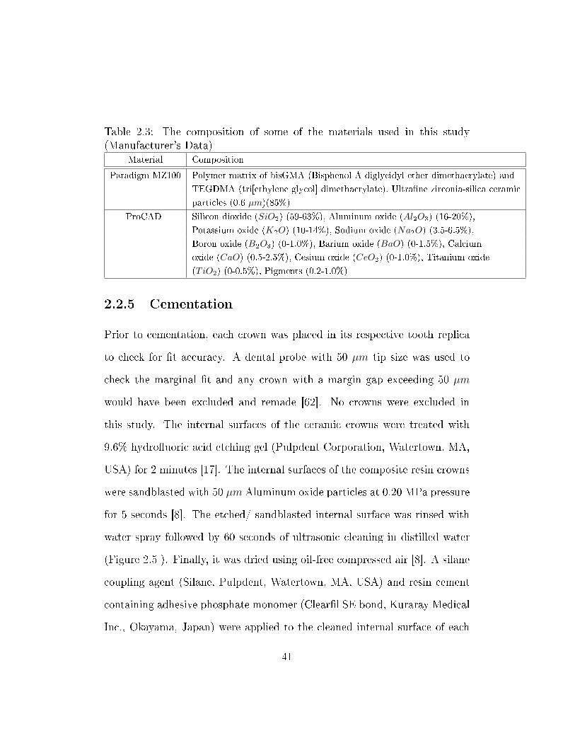
Table 2.3: The composition of some of the materials used in this study(Manufacturer's Data)
Material Composition
Paradigm MZ100 Polymer matrix of bisGMA (Bisphenol A diglycidyl ether dimethacrylate) and
TEGDMA (tri[ethylene glycol] dimethacrylate), Ultra�ne zirconia-silica ceramic
particles (0.6 µm)(85%)
ProCAD Silicon dioxide (SiO2) (59-63%), Aluminum oxide (Al2O3) (16-20%),
Potassium oxide (K2O) (10-14%), Sodium oxide (Na2O) (3.5-6.5%),
Boron oxide (B2O3) (0-1.0%), Barium oxide (BaO) (0-1.5%), Calcium
oxide (CaO) (0.5-2.5%), Cesium oxide (CeO2) (0-1.0%), Titanium oxide
(TiO2) (0-0.5%), Pigments (0.2-1.0%)
2.2.5 Cementation
Prior to cementation, each crown was placed in its respective tooth replica
to check for �t accuracy. A dental probe with 50 µm tip size was used to
check the marginal �t and any crown with a margin gap exceeding 50 µm
would have been excluded and remade [62]. No crowns were excluded in
this study. The internal surfaces of the ceramic crowns were treated with
9.6% hydro�uoric acid etching gel (Pulpdent Corporation, Watertown, MA,
USA) for 2 minutes [17]. The internal surfaces of the composite resin crowns
were sandblasted with 50 µm Aluminum oxide particles at 0.20 MPa pressure
for 5 seconds [8]. The etched/ sandblasted internal surface was rinsed with
water spray followed by 60 seconds of ultrasonic cleaning in distilled water
(Figure 2.5 ). Finally, it was dried using oil-free compressed air [8]. A silane
coupling agent (Silane, Pulpdent, Watertown, MA, USA) and resin cement
containing adhesive phosphate monomer (Clear�l SE bond, Kuraray Medical
Inc., Okayama, Japan) were applied to the cleaned internal surface of each
41
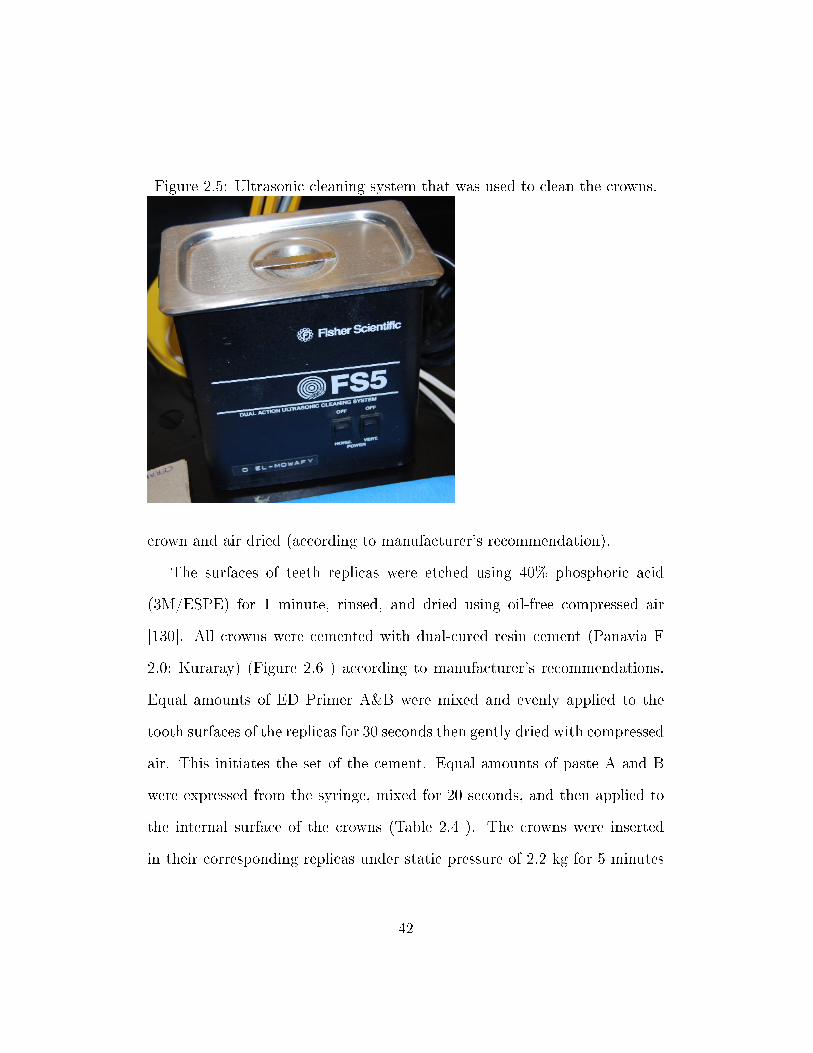
Figure 2.5: Ultrasonic cleaning system that was used to clean the crowns.
crown and air dried (according to manufacturer's recommendation).
The surfaces of teeth replicas were etched using 40% phosphoric acid
(3M/ESPE) for 1 minute, rinsed, and dried using oil-free compressed air
[130]. All crowns were cemented with dual-cured resin cement (Panavia F
2.0; Kuraray) (Figure 2.6 ) according to manufacturer's recommendations.
Equal amounts of ED Primer A&B were mixed and evenly applied to the
tooth surfaces of the replicas for 30 seconds then gently dried with compressed
air. This initiates the set of the cement. Equal amounts of paste A and B
were expressed from the syringe, mixed for 20 seconds, and then applied to
the internal surface of the crowns (Table 2.4 ). The crowns were inserted
in their corresponding replicas under static pressure of 2.2 kg for 5 minutes
42
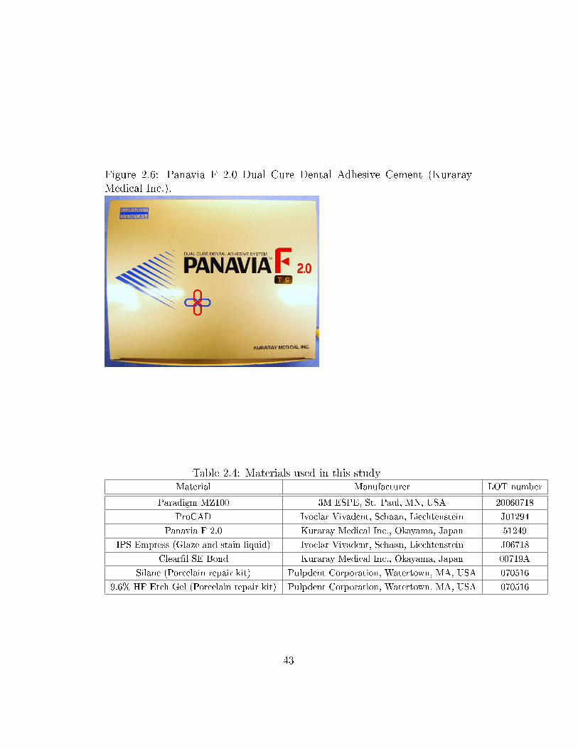
Figure 2.6: Panavia F 2.0 Dual Cure Dental Adhesive Cement (KurarayMedical Inc.).
Table 2.4: Materials used in this studyMaterial Manufacturer LOT number
Paradigm MZ100 3M ESPE, St. Paul, MN, USA 20060718
ProCAD Ivoclar Vivadent, Schaan, Liechtenstein J01294
Panavia F 2.0 Kuraray Medical Inc., Okayama, Japan 51249
IPS Empress (Glaze and stain liquid) Ivoclar Vivadent, Schaan, Liechtenstein J06718
Clear�l SE Bond Kuraray Medical Inc., Okayama, Japan 00719A
Silane (Porcelain repair kit) Pulpdent Corporation, Watertown, MA, USA 070516
9.6% HF Etch Gel (Porcelain repair kit) Pulpdent Corporation, Watertown, MA, USA 070516
43
[89] (Figure 2.7 ). The extruded excess cement was removed and each surface
(Buccal, Lingual, and occlusal) was light-cured (Optilux 501, Kerr Demetron,
Danbury, CT, USA) for 40 seconds. A layer of Oxyguard II was applied to the
margins for 3 minutes according to the manufacturer's instructions. Using
a caliper, the occluso-apical distance of each tooth was recorded before and
after cementation to verify the degree of seating (Figure 2.8 ). Any tooth
with more than 50 µm increase in that dimension as a result of cementation
would have been excluded and remade [130]. No crowns were excluded in
this study due to seating error. One hour following cementation, the crowns
were stored in distilled water at a temperature of 37oC for 1 week (Figure
2.9 , Figure 2.10 , and Figure 2.11 ). [10]
2.2.6 Cyclic Fatigue and Fracture Test
Each group of 20 crowns was randomly divided into two equal groups. One
half was loaded in the Instron machine (Instron, Canton, Mass) , a hydraulic
driven universal testing machine, using a cross head speed of 1 mm/min
(Figure 2.12 ). The load was applied along the long axis of the replicas
with hardened steel bar centered in the central groove (Figure 2.13 ). The
other half was subjected to mechanical cyclic loading in distilled water at
room temperature. The cyclic load ranged from 50 N to 600 N for 500,000
cycles at a frequency of 20 Hz (Figure 2.14 ). The Instron machine was
adjusted to stop if the deformation increased to more than 0.15 mm during
the mechanical cyclic loading. Those crowns that did not fracture during the
44
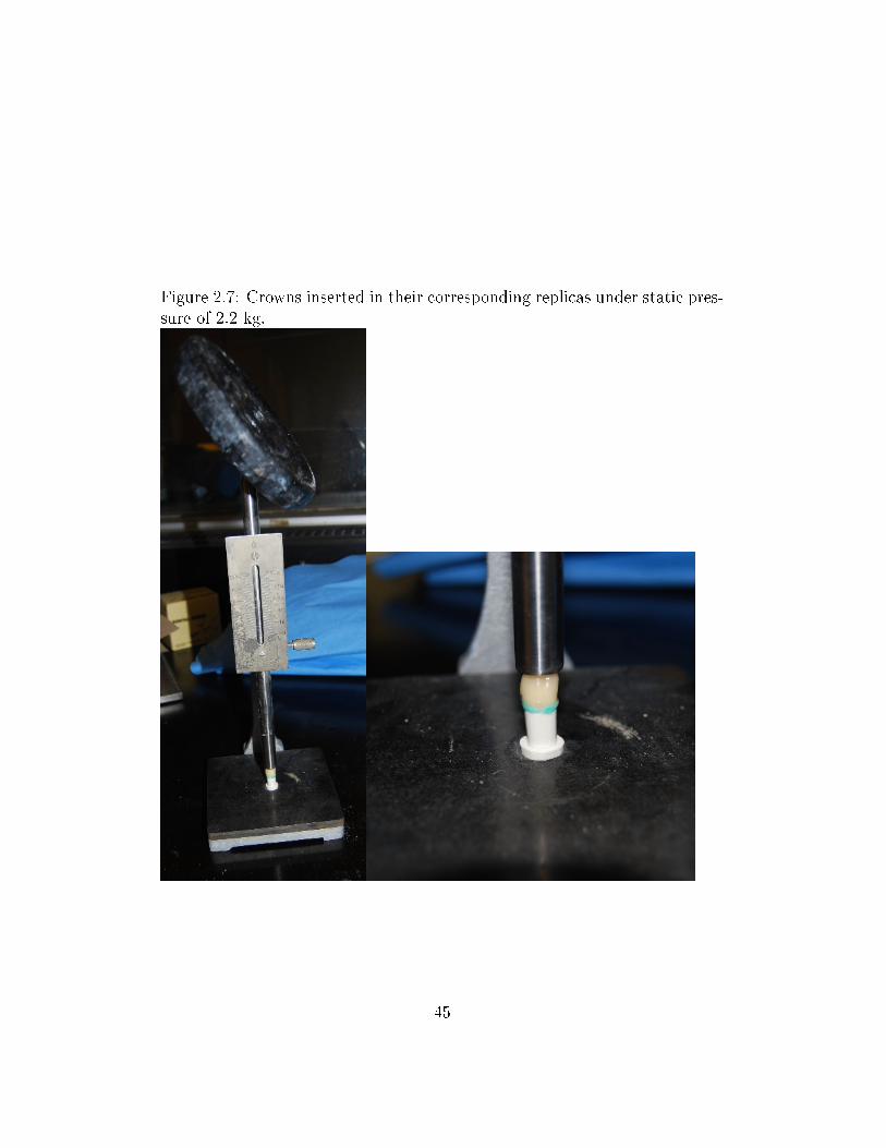
Figure 2.7: Crowns inserted in their corresponding replicas under static pres-sure of 2.2 kg.
45
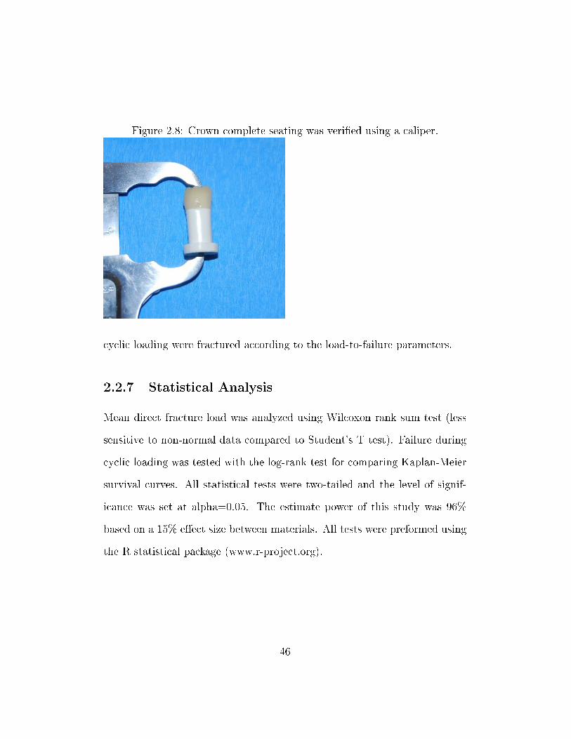
Figure 2.8: Crown complete seating was veri�ed using a caliper.
cyclic loading were fractured according to the load-to-failure parameters.
2.2.7 Statistical Analysis
Mean direct fracture load was analyzed using Wilcoxon rank sum test (less
sensitive to non-normal data compared to Student's T test). Failure during
cyclic loading was tested with the log-rank test for comparing Kaplan-Meier
survival curves. All statistical tests were two-tailed and the level of signif-
icance was set at alpha=0.05. The estimate power of this study was 96%
based on a 15% e�ect size between materials. All tests were preformed using
the R statistical package (www.r-project.org).
46
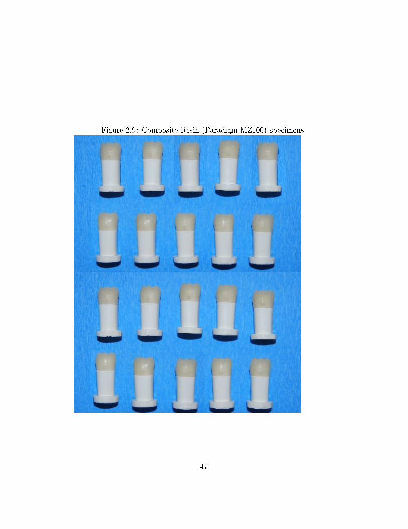
Figure 2.9: Composite Resin (Paradigm MZ100) specimens.
47
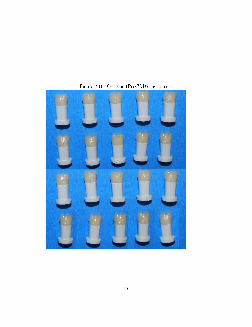
Figure 2.10: Ceramic (ProCAD) specimens.
48
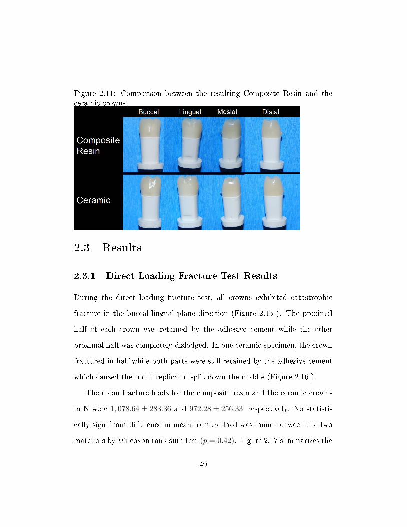
Figure 2.11: Comparison between the resulting Composite Resin and theceramic crowns.
2.3 Results
2.3.1 Direct Loading Fracture Test Results
During the direct loading fracture test, all crowns exhibited catastrophic
fracture in the buccal-lingual plane direction (Figure 2.15 ). The proximal
half of each crown was retained by the adhesive cement while the other
proximal half was completely dislodged. In one ceramic specimen, the crown
fractured in half while both parts were still retained by the adhesive cement
which caused the tooth replica to split down the middle (Figure 2.16 ).
The mean fracture loads for the composite resin and the ceramic crowns
in N were 1, 078.64 ± 283.36 and 972.28 ± 256.33, respectively. No statisti-
cally signi�cant di�erence in mean fracture load was found between the two
materials by Wilcoxon rank sum test (p = 0.42). Figure 2.17 summarizes the
49
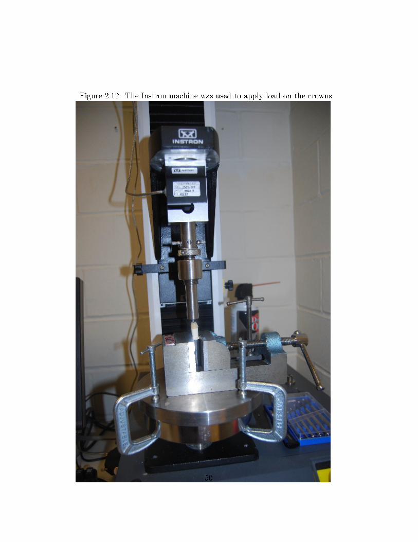
Figure 2.12: The Instron machine was used to apply load on the crowns.
50
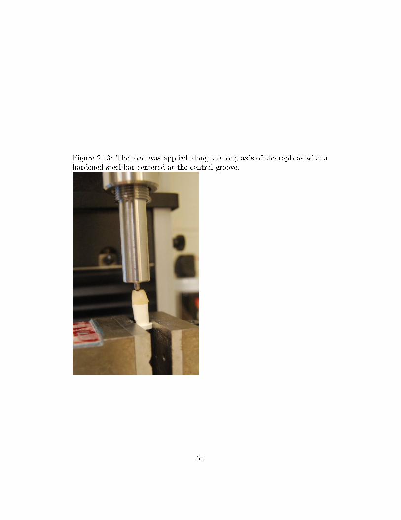
Figure 2.13: The load was applied along the long axis of the replicas with ahardened steel bar centered at the central groove.
51
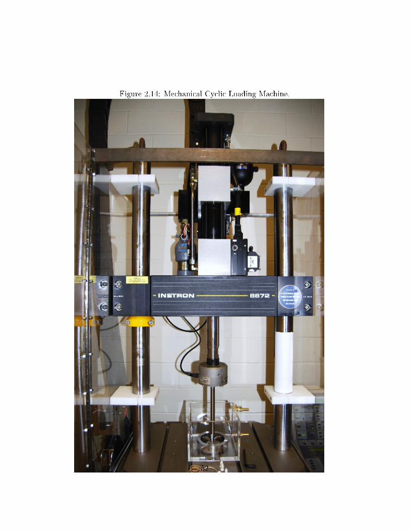
Figure 2.14: Mechanical Cyclic Loading Machine.
52
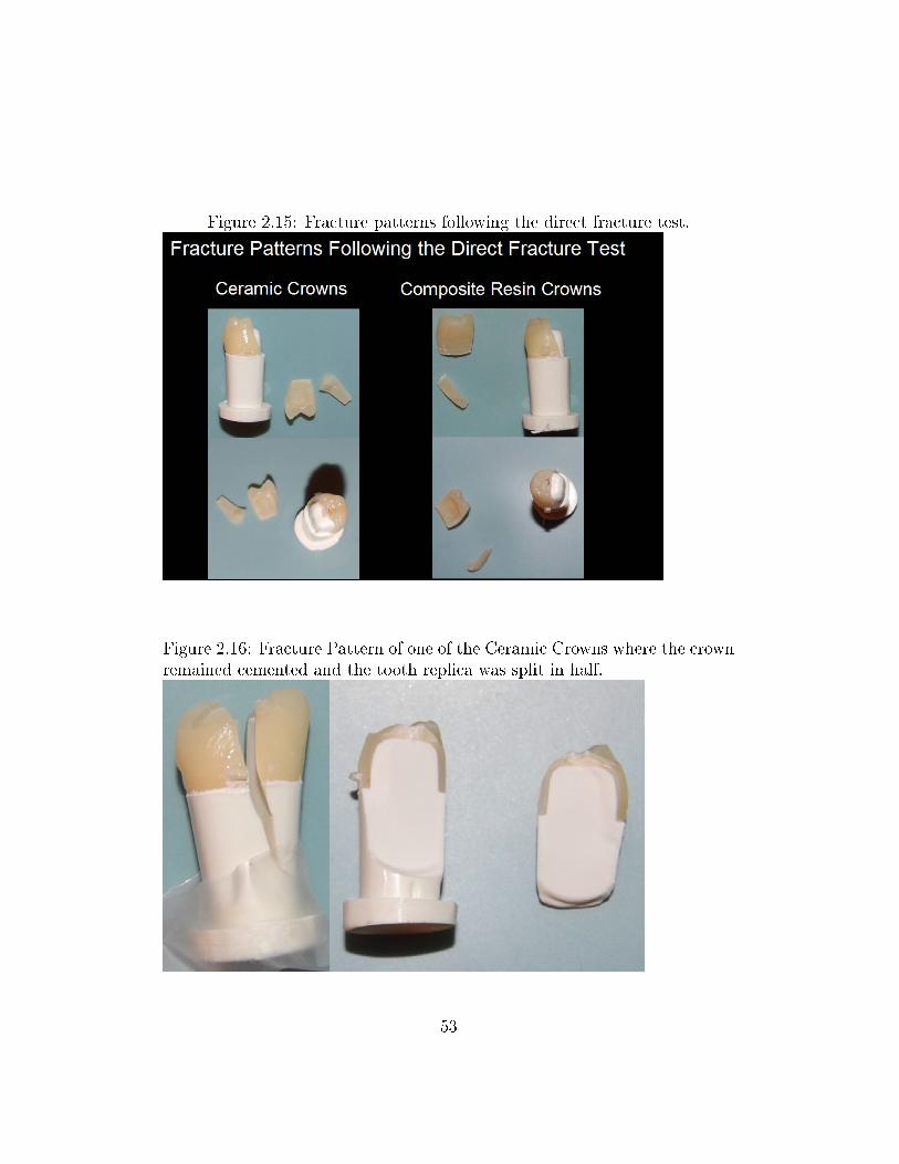
Figure 2.15: Fracture patterns following the direct fracture test.
Figure 2.16: Fracture Pattern of one of the Ceramic Crowns where the crownremained cemented and the tooth replica was split in half.
53
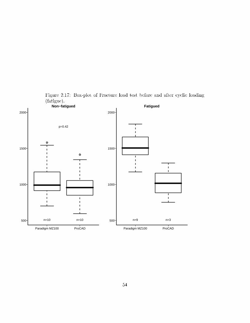
Figure 2.17: Box-plot of Fracture load test before and after cyclic loading(fatigue).
Paradigm MZ100 ProCAD
500
1000
1500
2000
Non−fatigued
n=10 n=10
p=0.42
Paradigm MZ100 ProCAD
500
1000
1500
2000
Fatigued
n=9 n=3
54
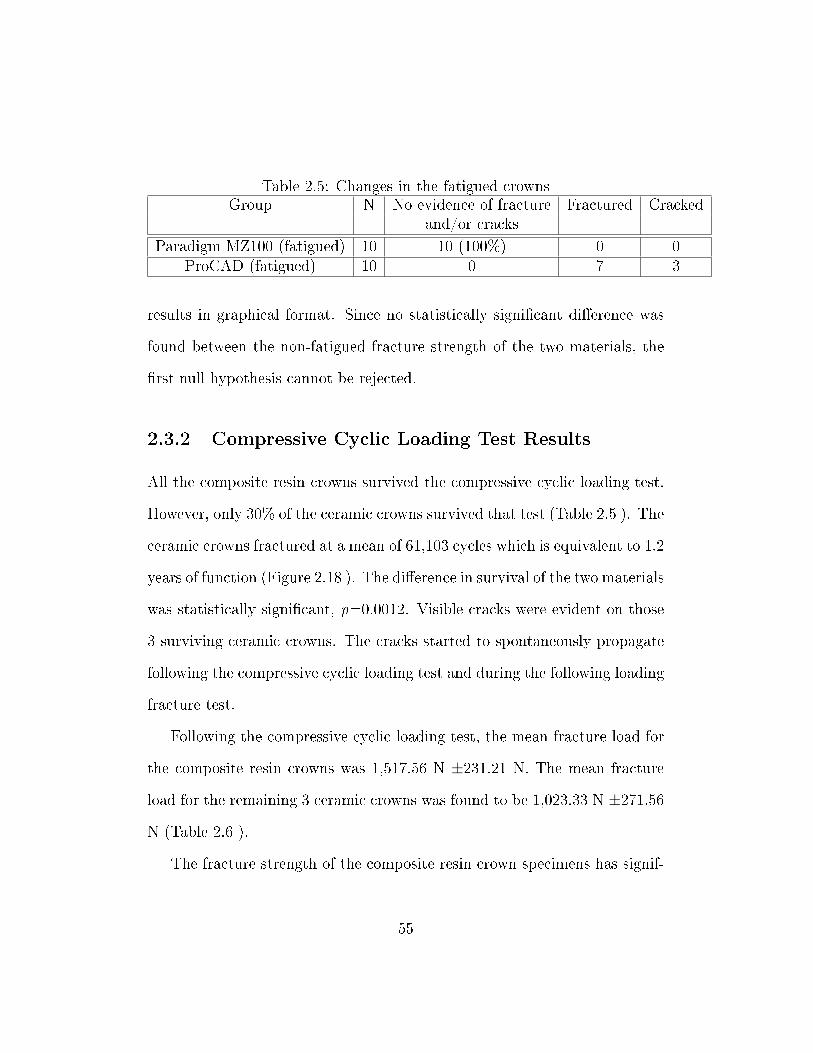
Table 2.5: Changes in the fatigued crownsGroup N No evidence of fracture Fractured Cracked
and/or cracks
Paradigm MZ100 (fatigued) 10 10 (100%) 0 0ProCAD (fatigued) 10 0 7 3
results in graphical format. Since no statistically signi�cant di�erence was
found between the non-fatigued fracture strength of the two materials, the
�rst null hypothesis cannot be rejected.
2.3.2 Compressive Cyclic Loading Test Results
All the composite resin crowns survived the compressive cyclic loading test.
However, only 30% of the ceramic crowns survived that test (Table 2.5 ). The
ceramic crowns fractured at a mean of 61,103 cycles which is equivalent to 1.2
years of function (Figure 2.18 ). The di�erence in survival of the two materials
was statistically signi�cant, p=0.0012. Visible cracks were evident on those
3 surviving ceramic crowns. The cracks started to spontaneously propagate
following the compressive cyclic loading test and during the following loading
fracture test.
Following the compressive cyclic loading test, the mean fracture load for
the composite resin crowns was 1,517.56 N ±231.21 N. The mean fracture
load for the remaining 3 ceramic crowns was found to be 1,023.33 N ±271.56
N (Table 2.6 ).
The fracture strength of the composite resin crown specimens has signif-
55
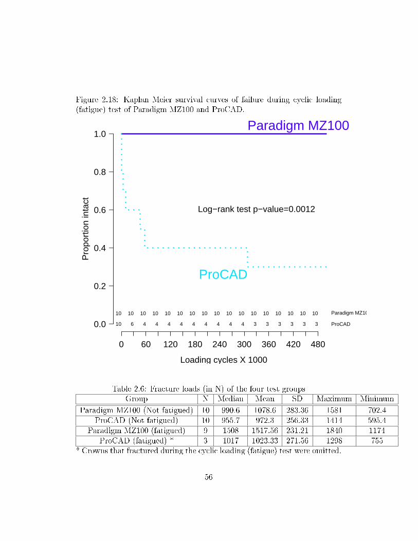
Figure 2.18: Kaplan Meier survival curves of failure during cyclic loading(fatigue) test of Paradigm MZ100 and ProCAD.
Loading cycles X 1000
Pro
port
ion
inta
ct
0 60 120 180 240 300 360 420 480
0.0
0.2
0.4
0.6
0.8
1.0
10 10 10 10 10 10 10 10 10 10 10 10 10 10 10 10 10 Paradigm MZ100
10 6 4 4 4 4 4 4 4 4 4 3 3 3 3 3 3 ProCAD
Paradigm MZ100
ProCAD
Log−rank test p−value=0.0012
Table 2.6: Fracture loads (in N) of the four test groupsGroup N Median Mean SD Maximum Minimum
Paradigm MZ100 (Not fatigued) 10 990.6 1078.6 283.36 1581 702.4ProCAD (Not fatigued) 10 955.7 972.3 256.33 1414 595.4
Paradigm MZ100 (fatigued) 9 1508 1517.56 231.21 1840 1174ProCAD (fatigued) * 3 1017 1023.33 271.56 1298 755
* Crowns that fractured during the cyclic loading (fatigue) test were omitted.
56
icantly increased following the compressive cyclic loading while the fracture
strength of the three surviving ceramic crown specimens demonstrated no sta-
tistically signi�cant di�erence to the non-fatigued specimens. Theoretically,
this leads to the rejection of the second null hypothesis for the composite
resin crown specimens. The second null hypothesis cannot be rejected for
the ceramic crown specimens. However, these results should be interpreted
cautiously since the conditions of the specimens were not standardized be-
tween pre- and post-fatiguing. While the specimens used for direct loading
fracture test were tested one week following cementation, those specimens
used for the compressive cyclic loading test were tested 3 to 4 months fol-
lowing cementation. In addition, the three surviving fatigued-ceramic crown
specimens demonstrated visible cracks prior the fracture test. This may have
resulted in inaccuracy of the second fracture test values. Since the di�erence
in survival of the ceramic and composite resin materials was statistically
signi�cant, the third null hypothesis can be rejected.
2.4 Discussion
2.4.1 Signi�cance of this research
Improvement in adhesive dentistry has made it possible for all-ceramic restora-
tions to be clinically successful. This encouraged the development of new
restorative materials to be used for anterior and posterior crowns, such as
ceramic and composite resin blocks that are used with CAD/CAM technol-
57
ogy. Although these blocks have been improving throughout the past several
years, a major disadvantage in this system is the adaptation of the restoration
and the surface smoothness following the milling procedure which may lead
to failure due to crack propagation and/or poor marginal adaptation. How-
ever, we believe that the new CEREC 3D software will prevent or minimize
such problems.
This study provides essential information regarding the in-vitro survival
of all-ceramic and composite crowns manufactured by CEREC 3D. The most
promising material will be selected for subsequent clinical trial supported by
industry and/or external funding agencies.
2.4.2 Fracture strength and fatigue resistance of Paradigm
MZ100
Since the introduction of composite resin blocks to be used for CEREC-3D
full-coverage crowns was fairly recent, studies addressing fracture strength
and fatigue resistance of composite resin crowns are very limited. For com-
posite resin crowns, Attia et al. [8] reported that the fracture load in N
for Paradigm MZ100 crowns was of 827.1 (86.3), 914.7 (131.7), and 955.9
(130.6) when used zinc phosphate, Fuji CEM, and RelyX ARC, respectively.
After subjecting his crowns to 3500 thermal cycles (58oC/4oC) and 600,000
masticatory cycles at 1.2 Hz ranging from 0 N to 49 N, the resulting frac-
ture loads in N of those fatigued composite resin crowns were reported to
58
be 772.3 (134.7), 923.6 (153.5), and 929.1 (148.5) when used zinc phosphate,
Fuji CEM, and RelyX ARC, respectively.
Tsitrou et al. [120] reported a fracture load of 1682 N (315 N) for
Paradigm MZ100 composite resin crowns and a fracture load of 1751 N (338
N) for minimally prepared composite resin crowns. Tyan et al. [122] found
that the fracture load for composite resin crowns was 2251N (714N) and
the fatigued fracture load of those crowns was 1464 N (266 N). In a di�er-
ent study [3], the mean fracture load for Paradigm MZ100 composite resin
crowns without fatigue and with 50,000 load cycles was stated to be 1680
N and 1330 N, respectively. In this study, the mean fracture load for of
Paradigm MZ100 crowns was 1,078.64 N (283.36 N) which falls within the
reported range of the mean fracture strengths (827.1 N to 2251 N).
All of the Paradigm MZ100 crowns subjected to cyclic loading survived
the test without any evidence of cracking. None of the previous limited stud-
ies reported any failure with Paradigm MZ100 crowns during cyclic loading
testing [8, 120, 122, 3]. However, the testing criteria in this study have
subjected the specimens to the most extreme testing conditions among the
previously reported studies.
The mean fracture load of the fatigued composite resin crowns was found
to be 1517.56 N (231.21 N). Most of the literature has reported a decrease in
fracture loads following the cyclic loading test [3, 8]. However, these studies
used di�erent cements than the one used in this study under di�erent cyclic
loading conditions. Attia and Kern [10] found that cyclic loading did not
59
decrease the median fracture load of crowns cemented with Panavia F. In
our study, the mean fracture load increased signi�cantly (p = 0.003). This
can be attributed to one or more of the following:
� The cyclic loading test high frequency (20 Hz) and load generated high
temperature that caused a higher degree of conversion in the resin ce-
ment and hence a more complete resin cure. However, the test was
conducted under water which would have acted as coolant and pre-
vented temperature rise.
� The specimens that received cyclic compressive loading were stored for
3 months in water prior testing due to unavailability of the Instron
machine for that period. This may have provided the resin cement
with more time to fully mature.
� The operator who conducted the direct fracture test is di�erent than
that who performed the cyclic loading and the following fracture test.
Inter-operator variability may have contributed to such results.
2.4.3 Fracture strength and fatigue resistance of Pro-
CAD
Attia and Kern [9] measured fracture load of ProCAD crowns to be 715.9
N (105.2 N) when used hydro�uoric acid etching and silane coupling agent
(Mirage ABC silane); and 708.4 N (108.7 N) when used phosphoric acid clean-
ing and Porcelain Liner-M primer. In a di�erent study, Attia and Kern [10]
60
recorded the fracture resistance of ProCAD crowns cemented with Panavia F
to be 960.2 N (211.8 N) and 809.2 N (96.4 N) without and with cyclic load-
ing, respectively. No statistically signi�cant di�erence was found between
the non-fatigued and fatigued ProCAD crowns when Panavia F was used for
cementation. Chen et al. [22] reported a fracture load of 2120 N (231 N) and
2254 N (186 N) for polished and oven glazed ProCAD crowns, respectively.
For the fatigued ProCAD crowns, Chen at al. reported a fracture load of 1613
(296) N and 2033 (413) N for polished and oven glazed crowns, respectively.
They found that prior cyclic loading decreased the fracture resistance of all
tested crowns signi�cantly. They also concluded that oven-glazing ProCAD
crowns improved their strength and fatigue properties signi�cantly. Stappert
et al. [115] studied partial coverage ProCAD crowns and recorded a mean
fracture strength of 2134 N (333 N) after subjecting all of the crowns to a
load of 49 N for 1.2 million masticatory cycles at 1.2 Hz. All of their Pro-
CAD specimens survived mastication simulation. Tyan et al. [122] reported
an initial load of 1250 N (255 N) and a fatigue load of 798 N (178 N) for
ProCAD crowns. Those crowns were subjected to 10,000 fatigue cycles with
a load that varied between the selected maximum value (40% of minimum
fracture load = 500 N) and a minimum value of about 1/3 of the maximum
load (166 N).
The recorded fracture resistance in this study for the ProCAD crowns
was 972.28 (256.33) N which falls within the literature reported means range
(715.9 N to 2254 N). The variability in the reported fracture loads can be
61
attributed to the use of di�erent cements, bonding techniques, abutment
types, and testing modalities.
As opposed to the previous studies that reported no ProCAD crown fail-
ure during the cyclic loading test, we experienced catastrophic fracture of
70 % and cracking of the remaining 30 % of our ProCAD specimens. While
most of the previous studies [9, 10, 115] used a load of 0-49 N during the
compressive cyclic loading test, our study used a range of 50-600 N when
fatiguing the specimens. This load falls into the highest range of forces that
crowns might be subjected to in the molar area [7]. For a given material,
the failure load vs. the no. of cycles required to fracture that material is
represented in the following graph (Figure 2.19 ). If the load applied during
the cyclic loading test is too low, the crown may never undergo failure as the
number of cycles required for the crown to break reaches in�nity. In those
fore-mentioned studies, a maximum load of 49 N might have been too low to
cause any catastrophic fracture. Tyan [122] used a cyclic load that is 13.3-40
% of the minimal load to fracture which corresponds to 166-500 N. However,
the number of cycles used was only 10,000 cycle which is 2% of the number of
cycles used in this study and believed to be too low to cause any catastrophic
fracture of the restorations.
62
Figure 2.19: Number of cycles required for restoration failure graph.
63
2.4.4 Fracture strength and fatigue resistance compar-
ison
In our study, Paradigm MZ100 crowns performed as well as ProCAD crowns
when subjected to direct fracture loads. There was no signi�cant di�erence
between both crowns in terms of direct fracture strength. All of the pre-
vious studies comparing Paradigm MZ100 crowns to CEREC manufactured
ceramic crowns have reported no signi�cant di�erence between the mean frac-
ture loads of both crown systems without cyclic loading [8, 122]. Similarly,
the previous studies have reported no failure of composite resin crowns when
subjected to compressive cyclic loading. This is consistent with the �ndings
of this study.
Although most clinicians assume that all-ceramic crowns have better me-
chanical properties when compared to composite resin crowns, we reported no
signi�cant di�erence in the mean direct fracture loads of Paradigm MZ100
and ProCAD crowns. This may be attributed to the optimized manufac-
turing conditions that CAD-CAM materials undergo eliminating the risk of
voids and volume defects [10, 9]. It may also be due to the fact that com-
posite resin crowns have improved elastic properties when compared to all
ceramic crowns [64]. As a result, during the process of loading, the composite
resin crowns may exhibit higher resiliency with more absorption of load, and
thus, the fracture load is increased [8]. Most published literature compar-
ing composite resin to ceramic various restorations reported similar �ndings
64
[25, 20, 19, 105]. Gracis et al. [45] concluded that composite resin reduced
the impact forces by 57% more than porcelain.
All of our composite resin crowns survived the rigorous compressive cyclic
loading test while only 30 % of the ceramic crowns survived the test. The
surviving 30 % ceramic crowns demonstrated visible cracks. When the milled
surfaces of the crowns were examined under 500 X magni�cation with the
Scanning Electron Microscope (SEM), a di�erence in the pattern of material
removal was observed. In the composite resin specimen, �ne grooves can
be seen on the milled surface indicating a plastic deformation mechanism
of material removal (Figure 2.20 ). However, ceramic specimens demon-
strated a surface typical of fracture mechanism material removal (Figure
2.21 ). The 3M Paradigm MZ100 technical product pro�le reported similar
�ndings. When the margins of milled crowns examined under 60 X SEM
magni�cation, the same broad contours and peaks can be seen in both crown
types which is re�ective of the margins shape. However, the margin edge
appears more sharply de�ned in the Paradigm MZ100 crown compared to
the ProCAD crown which also show chipping (Figure 2.22 ). While large
milling grooves matching the outer shape of the cutting bur can be seen in
both, smaller grooves corresponding to individual diamond grains can only
be seen on the Paradigm MZ100 material.
The fracture mechanism of material removal in the ProCAD crowns may
have introduced micro-cracks in the material during milling. Cyclic loading,
especially under wet conditions, results in propagation of micro-cracks that
65
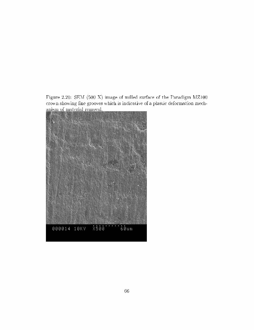
Figure 2.20: SEM (500 X) image of milled surface of the Paradigm MZ100crown showing �ne grooves which is indicative of a plastic deformation mech-anism of material removal.
66
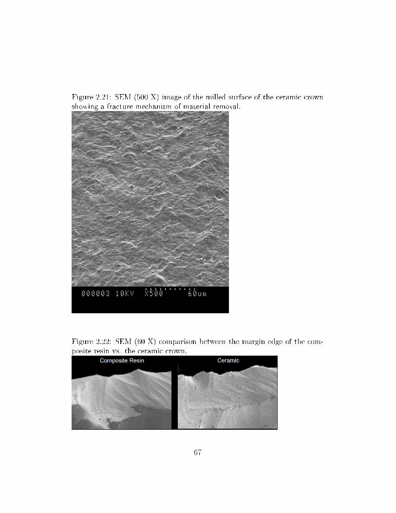
Figure 2.21: SEM (500 X) image of the milled surface of the ceramic crownshowing a fracture mechanism of material removal.
Figure 2.22: SEM (60 X) comparison between the margin edge of the com-posite resin vs. the ceramic crown.
67
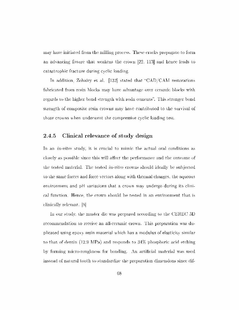
may have initiated from the milling process. These cracks propagate to form
an advancing �ssure that weakens the crown [22, 113] and hence leads to
catastrophic fracture during cyclic loading.
In addition, Zohairy et al. [132] stated that �CAD/CAM restorations
fabricated from resin blocks may have advantage over ceramic blocks with
regards to the higher bond strength with resin cements�. This stronger bond
strength of composite resin crowns may have contributed to the survival of
those crowns when underwent the compressive cyclic loading test.
2.4.5 Clinical relevance of study design
In an in-vitro study, it is crucial to mimic the actual oral conditions as
closely as possible since this will a�ect the performance and the outcome of
the tested material. The tested in-vitro crowns should ideally be subjected
to the same forces and force vectors along with thermal changes, the aqueous
environment and pH variations that a crown may undergo during its clini-
cal function. Hence, the crown should be tested in an environment that is
clinically relevant. [8]
In our study, the master die was prepared according to the CEREC 3D
recommendation to receive an all-ceramic crown. This preparation was du-
plicated using epoxy resin material which has a modulus of elasticity similar
to that of dentin (12.9 MPa) and responds to 34% phosphoric acid etching
by forming micro-roughness for bonding. An arti�cial material was used
instead of natural tooth to standardize the preparation dimensions since dif-
68
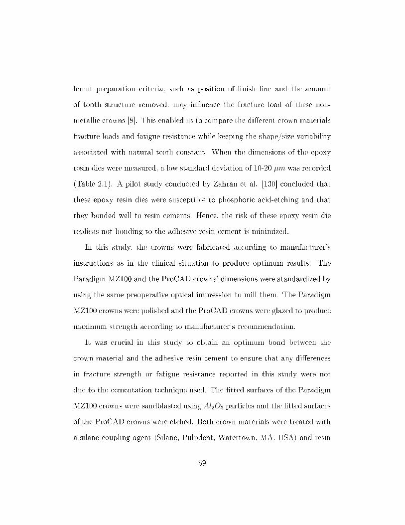
ferent preparation criteria, such as position of �nish line and the amount
of tooth structure removed, may in�uence the fracture load of these non-
metallic crowns [8]. This enabled us to compare the di�erent crown materials
fracture loads and fatigue resistance while keeping the shape/size variability
associated with natural teeth constant. When the dimensions of the epoxy
resin dies were measured, a low standard deviation of 10-20 µm was recorded
(Table 2.1). A pilot study conducted by Zahran et al. [130] concluded that
these epoxy resin dies were susceptible to phosphoric acid-etching and that
they bonded well to resin cements. Hence, the risk of these epoxy resin die
replicas not bonding to the adhesive resin cement is minimized.
In this study, the crowns were fabricated according to manufacturer's
instructions as in the clinical situation to produce optimum results. The
Paradigm MZ100 and the ProCAD crowns' dimensions were standardized by
using the same preoperative optical impression to mill them. The Paradigm
MZ100 crowns were polished and the ProCAD crowns were glazed to produce
maximum strength according to manufacturer's recommendation.
It was crucial in this study to obtain an optimum bond between the
crown material and the adhesive resin cement to ensure that any di�erences
in fracture strength or fatigue resistance reported in this study were not
due to the cementation technique used. The �tted surfaces of the Paradigm
MZ100 crowns were sandblasted using Al2O3 particles and the �tted surfaces
of the ProCAD crowns were etched. Both crown materials were treated with
a silane coupling agent (Silane, Pulpdent, Watertown, MA, USA) and resin
69
cement containing adhesive phosphate monomer (Clear�l SE bond, Kuraray
Medical Inc., Okayama, Japan). All crowns were cemented with the same
dual-curing phosphate-modi�ed resin cement Panavia F 2.0. No failure was
noted to occur between the cement and the crown material.
In the oral environment, non-metallic crowns fail as a result of slow crack
propagation that occurs due to fatigue under masticatory stress in a wet envi-
ronment. The crown specimens in this study were fatigued using a maximum
load of 600 N which corresponds to a high level of force a crown might be sub-
jected to in the posterior region. It was reported that the mean masticatory
forces during mastication and swallowing in humans to be approximately 40
N. However, the mean maximum posterior masticatory forces may vary from
150 N to 665 N [129, 8]. In our study, the crowns were loaded for 500,000
cycles which represents 10 years of clinical normal mastication function [125],
or about half a year of continuous bruxism as suggested by Kelly. [58]
The crack propagation in the oral cavity is accelerated by the presence of
saliva. All the compressive cyclic loading in this study was performed in wet
environment to simulate the hydrolytic e�ect of saliva on the crown mate-
rial �static fatigue: a stress-dependent chemical reaction between water and
surface �aws that causes the �aws to grow to a critical dimension, allowing
spontaneous crack propagation�. [10, 58]
Kelly [58] recommended several criteria for in-vitro failure testing for all-
ceramic crowns to be clinically relevant. Some of these recommendations
were followed in this study which includes using die material with elastic
70
modulus equivalent to that of dentin, preparing the dies according to clin-
ical recommendations, using crowns with dimensions similar to the clinical
situation, and using a reliable, commonly used luting cement.
2.4.6 Limitations of study design
1. Teeth replicas were used instead of natural teeth to allow for stan-
dardizing teeth sizes, preparation design, and di�erent factors a�ecting
the dentin modulus of elasticity. The dissimilarity in the coe�cient
of thermal expansion between the teeth replicas and the monolithic
crowns prevented thermocycling of the non-metallic crowns. In addi-
tion, epoxy resin is not identical to dentine in terms of cellular struc-
ture, bonding mechanism to the adhesive resin, and its physical and
mechanical properties.
2. In this study, all the forces during the cyclic loading were applied along
the vertical axes of the teeth replicas while ignoring all the other force
directions due to limitations in the loading machine. Crowns are sub-
jected to non-axial forces that is caused by the elliptical jaw movement
and the teeth contact on the cusps' inclines in the clinical environment
[46]. However, the majority of masticatory forces are vertical along the
long axis of the teeth in the molar area [46]. Due to the large damage
in�ected by the lateral forces [100], the clinical implication of the re-
sults of this in-vitro study should be limited only to the vertical loading
71
situation.
3. During the cyclic loading test, the use of high frequency of (20 Hz) com-
pared to a more clinically relevant frequency of (1-2 Hz) was inevitable
due to budget limitations. This high frequency may have lead to more
heat generation and may have not provided enough time for stress re-
laxation. In a study by Kelly et al. [60], a frequency of 20 Hz was
used for cyclic loading of leucite-reinforced all-ceramic crowns using a
staircase approach for loads between 200-800 N with a 100 N step size
for 1,000,000 cycles in water. They were able to record fracture loads
within reasonable clinical relevance. The high frequency used in this
study should not be a concern when comparing the two tested material
since both materials were fatigued under identical testing conditions.
4. The use of a stainless steel rounded tip rod would have increased the
contact pressure in the crown specimen compared to the clinical contact
pressure. This contact pressure is a�ected by the ratio of the elastic
modulus of the ceramic to that of the loading steel rod, and by the
radius of the tip of that steel rod. To overcome such limitation, we could
have used a loading ball with a modulus of elasticity lower than that
of the stainless steel rod to get a clinically relevant contact pressure.
However, the increase in the contact pressure due to using the stainless
steel rod with high modulus of elasticity and small diameter was applied
to both crown material specimens and should not alter the comparison
72
between them.
5. It is expected that crack initiation occurs at lower forces compared to
those needed for complete fracture. If a crack initiates in a crown, there
is a high possibility that the crack will propagate leading to catastrophic
fracture. In this study, the load needed to initiate cracking was not
recorded because the crack initiation was not accompanied by any drop
in the load since the loading piston was completely supported by the
intact crown. In this study, fracture loads were recorded when a sharp
drop in the load-displacement curve occurred. However, the load at
catastrophic fracture in not an adequate indicator of the load that the
material would withstand prior to crack initiation.
2.4.7 Future projects
According to the results of this study, the following need further investiga-
tions:
� In-vitro fracture strength and fatigue resistance of Paradigm MZ100
crowns compared to the gold-standard porcelain-fused-to-metal crowns.
This will provide signi�cant information regarding the strength and
durability of Paradigm MZ100 crowns compared to the clinically proven
strength and durability of porcelain-fused-to-metal crowns prior to con-
ducting expensive and time consuming clinical trials.
� If the Paradigm MZ100 crowns showed encouraging results in the pre-
73
vious in-vitro study, a clinical investigation of those resin composite
crowns should be conducted to test their durability and longevity un-
der the conditions of the oral environment and function.
2.5 Conclusions
Within the limitations of this in-vitro study, the following can be concluded:
1. There was no statistically-signi�cant di�erence between the in-vitro
mean compressive fracture loads of the resin composite (Paradigm
MZ100) and ceramic (ProCAD) molar crowns. However, this �nd-
ing should be cautiously interpreted since the two materials behaved
di�erently under conditions of cyclic loading.
2. Resin composite crowns sustained compressive cycling load without
any fractures while 70% of the ceramic crown specimens underwent
catastrophic fracture.
3. These in-vitro results suggest that resin composite molar crowns (Paradigm
MZ100) milled with CEREC-3D would be expected to resist fracture
well under forces of mastication.
74
Bibliography
[1] B. Abozenada, R. Pober, and R. Giordano. In-vitro wear of restorative
dental materials. In IADR Abstract no.1693, 2002.
[2] M. Aida, T. Hayakawa, and K. Mizukawa. Adhesion of composite to
porcelain with various surface conditions. The Journal of Prosthetic
Dentistry, 73(5):464�470, May 1995.
[3] K. AL-Gergawi, R. Giordano, and R. Pober. Cyclic fatigue of cad-cam
milled full thickness and layered crowns. In IADR Abstract no. 1367,
2004.
[4] K. J. Anusavice et al. Phillips' science of dental materials. W. B.
Saunders, Philadelphia, PA, 10th edition, 1996. pg. 585.
[5] K. J. Anusavice et al. Phillips' science of dental materials. W. B.
Saunders, Philadelphia, PA, 10th edition, 1996. pg. 607-608.
[6] K. J. Anusavice et al. Phillips' science of dental materials. W. B.
Saunders, Philadelphia, PA, 10th edition, 1996. pg. 593.
75
[7] K. J. Anusavice et al. Phillips' science of dental materials. W. B.
Saunders, Philadelphia, PA, 10th edition, 1996. pg. 66.
[8] A. Attia, K. M. Abdelaziz, S. Freitag, and M. Kern. Fracture load
of composite resin and feldspathic all-ceramic cad/cam crowns. The
Journal of Prosthetic Dentistry, 95(2):117�123, Feb 2006.
[9] A. Attia and M. Kern. Fracture strength of all-ceramic crowns luted
using two bonding methods. The Journal of Prosthetic Dentistry,
91(3):247�252, Mar 2004.
[10] A. Attia and M. Kern. In�uence of cyclic loading and luting agents
on the fracture load of two all-ceramic crown systems. The Journal of
Prosthetic Dentistry, 92(6):551�556, Dec 2004.
[11] N. G. Berg and T. Derand. A 5-year evaluation of ceramic inlays
(cerec). Swedish Dental Journal, 21(4):121�127, 1997.
[12] K. W. Bieniek and A. Peters. Clinical evaluation of ceramic restora-
tions machined by cad/cam technique. In W. H. Mormann, editor,
International symposium on computer restorations: state of the art of
the CEREC-method, pages 327�335. Quintessence, Chicago, 1991.
[13] A. Bindl, H. Luthy, andW. H. Mormann. Strength and fracture pattern
of monolithic cad/cam-generated posterior crowns. Dental Materials,
22(1):29�36, Jan 2006.
76
[14] A. Bindl and W. H. Morman. Survival rate of mono-ceramic and
ceramic-core cad/cam-generated anterior crowns over 2-5 years. Eu-
ropean Journal of Oral Sciences, 112(2):197�204, Apr 2004.
[15] A. Bindl and W. H. Mormann. Clinical and sem evaluation of all-
ceramic chair-side cad/cam-generated partial crowns. European Jour-
nal of Oral Sciences, 111(2):163�169, Apr 2003.
[16] M. B. Blatz. Long-term clinical success of all-ceramic posterior restora-
tions. Quintessence International, 33(6):415�426, Jun 2002.
[17] M. B. Blatz, A. Sadan, and M. Kern. Resin-ceramic bonding: a review
of the literature. The Journal of Prosthetic Dentistry, 89(3):268�274,
Mar 2003.
[18] A. W. Brauner and K. W. Bieniek. Seven years of clinical experience
with the cerec inlay system. In W. H. Mormann, editor, CAD/CIM
in aesthetic dentistry: CEREC 10 year anniversary symposium, pages
217�228. Quintessence, Chicago, 1996.
[19] B. D. Bremer andW. Geurtsen. Molar fracture resistance after adhesive
restoration with ceramic inlays or resin-based composites. American
Journal of Dentistry, 14(4):216�220, Aug 2001.
[20] P. A. Brunton, P. Cattell, F. J. Burke, and N. H. Wilson. Fracture
resistance of teeth restored with onlays of three contemporary tooth-
77
colored resin-bonded restorative materials. The Journal of Prosthetic
Dentistry, 82(2):167�171, Aug 1999.
[21] A. Cerutti, G. Venturi, and P. L. Sapelli. Seven year clinical evaluation
of 109 cad/cam inlays (abstract 2249). Journal of Dental Research, 77
(special issue B):913, 1998.
[22] H. Y. Chen, R. Hickel, J. C. Setcos, and K. H. Kunzelmann. E�ects
of surface �nish and fatigue testing on the fracture strength of cad-
cam and pressed-ceramic crowns. The Journal of Prosthetic Dentistry,
82(4):468�475, Oct 1999.
[23] L. Cho, J. Choi, Y. J. Yi, and C. J. Park. E�ect of �nish line vari-
ants on marginal accuracy and fracture strength of ceramic optimized
polymer/�ber-reinforced composite crowns. The Journal of Prosthetic
Dentistry, 91(6):554�560, Jun 2004.
[24] G. J. Christensen. Computerized restorative dentistry. state of the art.
Journal of the American Dental Association (1939), 132(9):1301�1303,
Sep 2001.
[25] P. H. P. Dalpino, C. E. Francischone, A. Ishikiriama, and E. B. Franco.
Fracture resistance of teeth directly and indirectly restored with com-
posite resin and indirectly restored with ceramic materials. American
Journal of Dentistry, 15(6):389�394, Dec 2002.
78
[26] H. Denissen, A. Dozic, J. van der Zel, and M. van Waas. Marginal �t
and short-term clinical performance of porcelain-veneered cicero, cerec,
and procera onlays. The Journal of Prosthetic Dentistry, 84(5):506�
513, Nov 2000.
[27] A. M. Diaz-Arnold, M. A. Vargas, and D. R. Haselton. Current status
of luting agents for �xed prosthodontics. The Journal of Prosthetic
Dentistry, 81(2):135�141, Feb 1999.
[28] J. L. Drummond. Ceramic behavior under di�erent environmental con-
ditions. dental materials in vivo: Aging and related phenomena. In
G. Eliades, T. Eliades, W. A. Brantley, and D. C. Watts, editors, Den-
tal Materials In Vivo: Aging and Related Phenomena, pages 35�46.
Quintessence, 2003.
[29] O. El-Mowafy and J. Brochu. Longevity and clinical performance of
ips-empress ceramic restorations�a literature review. Journal of the
Canadian Dental Association, 68(4):233�237, Apr 2002.
[30] D. Estafan, F. Dussetschleger, C. Agosta, and S. Reich. Scanning
electron microscope evaluation of cerec ii and cerec iii inlays. General
Dentistry, 51(5):450�454, Sep-Oct 2003.
[31] A. G. Evans. Slow crack growth in brittle materials under dynamic
loading conditions. International Journal of Fracture, 10(2):251�259,
1974.
79
[32] A. G. Evans and H. Johnson. The fracture stress and its dependence on
slow crack growth. Journal of Materials Science, 10(2):214�222, 1975.
[33] P. L. Fan. Porcelain repair materials. council on dental materials, in-
struments and equipment. Journal of the American Dental Association,
122(8):124, 126, 128�124, 126, 130, Aug 1991.
[34] D. J. Fasbinder. Restorative material options for cad/cam restorations.
Compendium of Continuing Education in Dentistry, 23(10):911�924,
Oct 2002.
[35] D. J. Fasbinder. CEREC 3D Operator's manual, volume 2. Cereconline
(Cited 2005 Apr 3), 2003.
[36] D. J. Fasbinder. Clinical performance of chairside cad/cam restora-
tions. Journal of the American Dental Association, 137 Suppl:22S�31S,
Sep 2006.
[37] D. J. Fasbinder. Predictable cerec occlusal relationships. In W. H.
Mormann, editor, State of the Art of CAD/CAM Restorations: 20
Years of CEREC, pages 93�100. Quintessence, 2006.
[38] D. J. Fasbinder, J. B. Dennison, D. R. Heys, and K. Lampe. The
clinical performance of cad/cam-generated composite inlays. Journal
of the American Dental Association, 136(12):1714�1723, Dec 2005.
[39] D. J. Fasbinder, K. Lampe, J. B. Dennison, M. C. Peters, and Ne-
matollahi K. Three year clinical performance of cad/cim generated
80
ceramic onlays (abstract 1883). Journal of Dental Research, 80 (spe-
cial issue):271, 2001.
[40] D. J. Fasbinder, K. Lampe, J. B. Dennison, M. C. Peters, and K. Ne-
matollahi. Clinical performance of CAD/CIM generated ceramic onlays
(abstract 2711). Journal of Dental Research, 78, 1999.
[41] J. F. Jr. Fowler. Allergic contact dermatitis to metals. American
Journal of Contact Dermatitis, 1:212�223, 1990.
[42] R. Giordano. Materials for chairside cad/cam-produced restorations.
Journal of the American Dental Association (1939), 137 Suppl:14S�
21S, Sep 2006.
[43] R. Giordano, K. Kanchanatawewat, P. Asvanund, and D. Nathanson.
Flexural strength of ceramics for celay restorations (abstract 860).
Journal of Dental Research, 75:125, 1996.
[44] S. Gladys, B. Van Meerbeek, S. Inokoshi, G. Willems, M. Braem,
P. Lambrechts, and G. Vanherle. Clinical and semiquantitative
marginal analysis of four tooth-coloured inlay systems at 3 years. Jour-
nal of Dentistry, 23(6):329�338, Dec 1995.
[45] S. E. Gracis, J. I. Nicholls, J. D. Chalupnik, and R. A. Yuodelis. Shock-
absorbing behavior of �ve restorative materials used on implants. The
International Journal of Prosthodontics, 4(3):282�291, 1991.
81
[46] H. Graf. Occlusal forces during function. In N. H. Rowe, editor, Pro-
ceedings of symposium on Occlusion: Research in Form and Function,
pages 90�111. Ann Arbor, Michigan, University of Michigan Press,
September 1975.
[47] L. H. He and M. V. Swain. Nanoindentation derived stress-strain prop-
erties of dental materials. Dental Materials, 23(7):814�821, Jul 2007.
[48] M. Herrguth, M. Wichmann, and S. Reich. The aesthetics of all-ceramic
veneered and monolithic cad/cam crowns. Journal of Oral Rehabilita-
tion, 32(10):747�752, Oct 2005.
[49] H. O. Heymann, S. C. Bayne, J. R. Sturdevant, A. D. Wilder Jr, and
T. M. Roberson. The clinical performance of cad-cam-generated ce-
ramic inlays: a four-year study. Journal of the American Dental Asso-
ciation (1939), 127(8):1171�1181, Aug 1996.
[50] R. Hickel and J. Manhart. Longevity of restorations in posterior teeth
and reasons for failure. Journal of Adhesive Dentistry, 3(1):45�64, 2001.
[51] F. G. Hougeir, J. A. Yiannias, M. L. Hinni, J. G. Hentz, and R. A.
el Azhary. Oral metal contact allergy: a pilot study on the cause of
oral squamous cell carcinoma. International Journal of Dermatology,
45(3):265�271, Mar 2006.
[52] M. B. Huerzeler, H. Fett, and W. H. Morman. Clinical evaluation
of ceramic restorations machined by cad/cam technique. In W. H.
82
Mormann, editor, International symposium on computer restorations:
state of the art of the CEREC-method, pages 327�335. Quintessence,
Chicago, 1991.
[53] S. Inokoshi, B. Van Meerbeek, G. Willems, P. Lambrechts, M. Braem,
and G. Vanherle. Marginal accuracy of cad/cam inlays made with the
original and the updated software. Journal of Dentistry, 20(3):171�177,
Jun 1992.
[54] B. P. Isenberg, M. E. Essig, and K. F. Leinfelder. Three-year clini-
cal evaluation of cad/cam restorations. Journal of Esthetic Dentistry,
4(5):173�176, Sep-Oct 1992.
[55] K. Kamada, K. Yoshida, and M. Atsuta. E�ect of ceramic surface
treatments on the bond of four resin luting agents to a ceramic material.
The Journal of Prosthetic Dentistry, 79(5):508�513, May 1998.
[56] E. C. Kao and W. M. Johnston. Fracture incidence on debonding of
orthodontic brackets from porcelain veneer laminates. The Journal of
Prosthetic Dentistry, 66(5):631�637, Nov 1991.
[57] K. Kawai, B. P. Isenberg, and K. F. Leinfelder. E�ect of gap dimension
on composite resin cement wear. Quintessence International, 25(1):53�
58, Jan 1994.
83
[58] J. R. Kelly. Clinically relevant approach to failure testing of all-ceramic
restorations. The Journal of Prosthetic Dentistry, 81(6):652�661, Jun
1999.
[59] J. R. Kelly. Dental ceramics: current thinking and trends. Dental
Clinics of North America, 48(2):513�530, Apr 2004.
[60] J. R. Kelly, B. D. Hunter, and M. R. Brenyo. Simulating clinical failure
during in vitro testing of all-ceramic crowns (abstract 1175). Journal
of Dental Research, 77 (special issue B):778, 1998.
[61] I. Krejci, F. Lutz, and M. Reimer. Wear of cad/cam ceramic inlays:
restorations, opposing cusps, and luting cements. Quintessence Inter-
national, 25(3):199�207, Mar 1994.
[62] N. Krämer, U. Lohbauer, and R. Frankenberger. Adhesive luting of in-
direct restorations. American Journal of Dentistry, 13(Spec No):60D�
76D, Nov 2000.
[63] B. Kränke, M. Binder, J. Derhaschnig, P. Komericki, D. Pirkhammer,
V. Ziegler, and W. Aberer. Patch testing with the "austrian standard
series"�epidemiologic test values and results. Wien Klin Wochenschr,
107(11):323�330, 1995.
[64] K. H. Kunzelmann, B. Jelen, A. Mehl, and R. Hickel. Wear evalua-
tion of mz100 compared to ceramic cad/cam materials. International
Journal of Computerized Dentistry, 4(3):171�184, Jul 2001.
84
[65] R. Laeijendecker and T. van Joost. Oral manifestations of gold allergy.
Journal of the American Academy of Dermatology, 30(2 Pt 1):205�209,
Feb 1994.
[66] K. F. Leinfelder, B. P. Isenberg, and M. E. Essig. A new method
for generating ceramic restorations: a cad-cam system. Journal of the
American Dental Association (1939), 118(6):703�707, Jun 1989.
[67] D. Magnuson, A. Oden, and I. Krystek. Clinical evaluation of cerec
restorations. In W. H. Mormann, editor, International symposium on
computer restorations: state of the art of the CEREC-method, pages
339�346. Quintessence, chicago, 1991.
[68] J. Manhart, H. Chen, G. Hamm, and R. Hickel. Buonocore memorial
lecture: Review of the clinical survival of direct and indirect restora-
tions in posterior teeth of the permanent dentition. Operative Dentistry,
29(5):481�508, 2004.
[69] J. G. Marks, D. V. Belsito, V. A. DeLeo, J. F. Fowler, A. F. Fran-
sway, H. I. Maibach, C. G. Mathias, M. D. Pratt, R. L. Rietschel, E. F.
Sherertz, F. J. Storrs, and J. S. Taylor. North american contact der-
matitis group patch-test results, 1996-1998. Archives of Dermatology,
136(2):272�273, Feb 2000.
85
[70] N. Martin and N. M. Jedynakiewicz. Clinical performance of cerec
ceramic inlays: a systematic review. Dental Materials, 15(1):54�61,
Jan 1999.
[71] E. A. McLaren and R. A. Giordano. Zirconia-based ceramics: ma-
terial properties, esthetics, and layering techniques of a new veneer-
ing porcelain, vm9, high-alumina frameworks. Quintessence of Dental
Technology, 28:1�12, 2005.
[72] E. A. McLaren, R. A. Giordano, R. Pober, and B. Abozenada. Material
testing and layering techniques of a new two-phase all glass veneering
porcelain. Quintessence of Dental Technology, 26:69�81, 2003.
[73] J. W. McLean, J. R. Hubbard, and M. I. Kedge. The Science and
Art of Dental Ceramics, chapter II: Construction of Porcelain Veneer
Crowns: Technical Considerations, page 45. Quintessence, Chicago,
1979.
[74] J. W. McLean and J. A. von Fraunhofer. The estimation of cement �lm
thickness by an in vivo technique. British Dental Journal, 131(3):107�
111, Aug 1971.
[75] P. F. Messer, V. Piddock, and C. H. Lloyd. The strength of dental
ceramics. Journal of Dentistry, 19(1):51�55, Feb 1991.
86
[76] M. K. Molin and S. L. Karlsson. A randomized 5-year clinical eval-
uation of 3 ceramic inlay systems. The International Journal of
Prosthodontics, 13(3):194�200, May-Jun 2000.
[77] T. Morikawa, H. Matsumura, and M. Atsuta. Bonding of a mica-based
castable ceramic material with a tri-n-butylborane-initiated adhesive
resin. Journal of Oral Rehabilitation, 23(7):450�455, Jul 1996.
[78] W. H. Mormann. The evolution of the cerec system. Journal of the
American Dental Association, 137 Suppl:7S�13S, Sep 2006.
[79] W. H. Mormann and A. Bindl. The new creativity in ceramic restora-
tions: dental cad-cim. Quintessence International, 27(12):821�828, Dec
1996.
[80] W. H. Mormann, T. Gotsch, I. Krejci, F. Lutz, and F. Barbakow.
Clinical status of 94 cerec ceramic inlays after 3 years in situ. In W. H.
Mormann, editor, International symposium on computer restorations:
state of the art of the CEREC-method, pages 355�362. Quintessence,
Chicago, 1991.
[81] W. H. Mormann and I. Krejci. Cinical and sem evaluation of cerec
inlays after 5 years in situ. In W. H. Mormann, editor, International
symposium on computer restorations: state of the art of the CEREC-
method, pages 25�32. Quintessence, Chicago, 1991.
87
[82] W. H. Mormann and J. Schug. Grinding precision and accuracy of �t
of cerec 2 cad-cim inlays. Journal of the American Dental Association,
128(1):47�53, Jan 1997.
[83] T. Nakamura, N. Dei, T. Kojima, and K. Wakabayashi. Marginal and
internal �t of cerec 3 cad/cam all-ceramic crowns. The International
Journal of Prosthodontics, 16(3):244�248, May-Jun 2003.
[84] T. Namikoshi. Case of oral lichen planus due to dental metal allergy.
Nihon Hotetsu Shika Gakkai Zasshi, 50(3):461�463, Jul 2006.
[85] G. Neiva, P. Yaman, J. B. Dennison, M. E. Razzoog, and B. R. Lang.
Resistance to fracture of three all-ceramic systems. Journal of Esthetic
Dentistry, 10(2):60�66, 1998.
[86] G. R. Norman and D. L. Streiner. Biostatistics : the bare essentials.
B.C. Decker, Hamilton, 3rd edition, 2008. Page 324.
[87] T. Otto and S. De Nisco. Computer-aided direct ceramic restorations:
a 10-year prospective clinical study of cerec cad/cam inlays and onlays.
The International Journal of Prosthodontics, 15(2):122�128, Mar-Apr
2002.
[88] U. Pallesen and J. W. van Dijken. An 8-year evaluation of sintered ce-
ramic and glass ceramic inlays processed by the cerec cad/cam system.
European Journal of Oral Sciences, 108(3):239�246, Jun 2000.
88
[89] K. Pallis, J. A. Griggs, R. D. Woody, G. E. Guillen, and A. W. Miller.
Fracture resistance of three all-ceramic restorative systems for posterior
applications. The Journal of Prosthetic Dentistry, 91(6):561�569, Jun
2004.
[90] A. Posselt and T. Kerschbaum. Longevity of 2328 chairside cerec inlays
and onlays. International Journal of Computerized Dentistry, 6(3):231�
248, Jul 2003.
[91] S. Reich, M. Wichmann, E. Nkenke, and P. Proeschel. Clinical �t of all-
ceramic three-unit �xed partial dentures, generated with three di�erent
cad/cam systems. European Journal of Oral Sciences, 113(2):174�179,
Apr 2005.
[92] B. Reiss. Clinical results of cerec inlays in a dental practice over a
period of 18 years. International Journal of Computerized Dentistry,
9(1):11�22, Jan 2006.
[93] B. Reiss and W. Walther. Survival analysis and clinical evaluation of
cerec restorations in a private practice. In W. H. Mormann, editor,
International symposium on computer restorations: state of the art of
the CEREC-method, pages 215�223. Quintessence, Chicago, 1991.
[94] B. Reiss andW.Walther. Clinical long-term results and 10-year kaplan-
meier analysis of cerec restorations. International Journal of Comput-
erized Dentistry, 3(1):9�23, Jan 2000.
89
[95] S.F. Rosenstiel, F. Martin, and J. Fujimoto. Contemporary Fixed
Prosthodontics. Mosby St. Louis, 4th edition, 2001. Page 262-271.
[96] S.F. Rosenstiel, F. Martin, and J. Fujimoto. Contemporary Fixed
Prosthodontics. Mosby St. Louis, 4th edition, 2001. Page 643-672.
[97] M. Rosentritt, M. Behr, R. Lang, and Handel G. In�uence of cement
type on the marginal adaptation of all-ceramic mod inlays. Dental
Materials, 20(5):463�469, Jun 2004.
[98] R. P. Rusin. Properties and applications of a new composite block
for cad/cam. Compendium of Continuing Education in Dentistry, 22(6
Suppl):35�41, Jun 2001.
[99] R. P. Rusin, R. P. Costin, and L. A. Goldsworthy. Tool life-time on the
cerec 2 system (abstract 582). Journal of Dental Research, 80, 2001.
[100] K. Sasaki, A. G. Hannam, and W. W. Wood. Relationships between
the size, position, and angulation of human jaw muscles and unilateral
�rst molar bite force. Journal of Dental Research, 68(3):499�503, Mar
1989.
[101] R. R. Seghi and J. A. Sorensen. Relative �exural strength of six
new ceramic materials. The International Journal of Prosthodontics,
8(3):239�246, 1995.
[102] A. Sertoli, S. Francalanci, MC Acciai, and M. Gola. Epidemiological
survey of contact dermatitis in Italy (1984-1993) by GIRDCA (Gruppo
90
Italiano Ricerca Dermatiti da Contatto e Ambientali). American Jour-
nal of Contact Dermatitis, 10(1):18�30, 1999.
[103] H. T. Shillingburg. Fundamentals of �xed prosthodontics. Chicago:
Quintessence Pub. Co., 3rd edition, 1997. page 455.
[104] H. T. Shillingburg. Fundamentals of �xed prosthodontics. Chicago:
Quintessence Pub. Co., 3rd edition, 1997. page 433-454.
[105] A. Shor, J. I. Nicholls, K. M. Phillips, and W. J. Libman. Fatigue load
of teeth restored with bonded direct composite and indirect ceramic
inlays in mod class ii cavity preparations. The International Journal
of Prosthodontics, 16(1):64�69, 2003.
[106] S. Siervo, A. Pampalone, P. Siervo, and R. Siervo. Where is the gap?
machinable ceramic systems and conventional laboratory restorations
at a glance. Quintessence International, 25(11):773�779, Nov 1994.
[107] R. Silva, F. Pereira, O. Bordalo, E. Silva, A. Barros, M. Gonçalo,
T. Correia, G. Pessoa, A. Baptista, and M. Pecegueiro. Contact allergy
to gold sodium thiosulfate. a comparative study. Contact Dermatitis,
37(2):78�81, Aug 1997.
[108] G. Sjogren, M. Bergman, M. Molin, and C. Bessing. A clinical ex-
amination of ceramic (cerec) inlays. Acta Odontologica Scandinavica,
50(3):171�178, Jun 1992.
91
[109] G. Sjogren, R. Lantto, A. Granberg, B. O. Sundstrom, and A. Till-
berg. Clinical examination of leucite-reinforced glass-ceramic crowns
(empress) in general practice: a retrospective study. The International
Journal of Prosthodontics, 12(2):122�128, Mar-Apr 1999.
[110] G. Sjogren, M. Molin, and J. W. van Dijken. A 5-year clinical evalua-
tion of ceramic inlays (cerec) cemented with a dual-cured or chemically
cured resin composite luting agent. Acta Odontologica Scandinavica,
56(5):263�267, Oct 1998.
[111] G. Sjogren, M. Molin, and J. W. Van Dijken. A 10-year prospective
evaluation of cad/cam-manufactured (cerec) ceramic inlays cemented
with a chemically cured or dual-cured resin composite. The Interna-
tional Journal of Prosthodontics, 17(2):241�246, Mar-Apr 2004.
[112] G. Sjogren, G. Sletten, and J. E. Dahl. Cytotoxicity of dental alloys,
metals, and ceramics assessed by millipore �lter, agar overlay, and mtt
tests. The Journal of Prosthetic Dentistry, 84(2):229�236, Aug 2000.
[113] L. C. Sobrinho, M. J. Cattell, R. H. Glover, and J. C. Knowles. Investi-
gation of the dry and wet fatigue properties of three all-ceramic crown
systems. The International Journal of Prosthodontics, 11(3):255�262,
1998.
92
[114] I. Stangel, D. Nathanson, and C. S. Hsu. Shear strength of the compos-
ite bond to etched porcelain. Journal of Dental Research, 66(9):1460�
1465, Sep 1987.
[115] C. F. Stappert, P. C. Guess, S. Chitmongkolsuk, T. Gerds, and J. R.
Strub. All-ceramic partial coverage restorations on natural molars.
masticatory fatigue loading and fracture resistance. American Journal
of Dentistry, 20(1):21�26, Feb 2007.
[116] J. R. Strub and S. M. Beschnidt. Fracture strength of 5 di�erent all-
ceramic crown systems. The International Journal of Prosthodontics,
11(6):602�609, Nov-Dec 1998.
[117] J. Tinschert, D. Zwez, R. Marx, and K. J. Anusavice. Structural relia-
bility of alumina-, feldspar-, leucite-, mica- and zirconia-based ceram-
ics. Journal of Dentistry, 28(7):529�535, Sep 2000.
[118] R. R. Torgerson, M. D. P. Davis, A. J. Bruce, S. A. Farmer, and
R. S. Rogers. Contact allergy in oral disease. Journal of the American
Academy of Dermatology, 57(2):315�321, Aug 2007.
[119] L. Trost, S. Stines, and L. Burt. Making informed decisions about
incorporating a cad/cam system into dental practice. Journal of the
American Dental Association (1939), 137 Suppl:32S�36S, Sep 2006.
93
[120] E. A. Tsitrou, M. Helvatjoglu-Antoniades, S.E. Northeast, and R. Van
Noort. Fracture resistance of minimally prepared cerec crowns. In
IADR Abstract no. 85781, 2006.
[121] E. A. Tsitrou, S. E. Northeast, and R. van Noort. Evaluation of the
marginal �t of three margin designs of resin composite crowns using
cad/cam. Journal of Dentistry, 35(1):68�73, Jan 2007.
[122] B. Tyan, R. Pober, and R. Giordano. Fatigue of cad/cam milled crowns.
In IADR Abstract no. 3963, 2002.
[123] S. M. Wiederhorn. Moisture assisted crack growth in ceramics. Inter-
national Journal of Fracture, 4(2):171�177, 1968.
[124] M. G. Wiley. E�ects of porcelain on occluding surfaces of restored
teeth. The Journal of Prosthetic Dentistry, 61(2):133�137, Feb 1989.
[125] H. W. Wiskott, J. I. Nicholls, and U. C. Belser. Stress fatigue: basic
principles and prosthodontic implications. The International Journal
of Prosthodontics, 8(2):105�116, 1995.
[126] D. M. Wolf, J. M. Powers, and K. L. O'Keefe. Bond strength of com-
posite to porcelain treated with new porcelain repair agents. Dental
Materials, 8(3):158�161, May 1992.
[127] K. T. Wrbas, N. Hein, J. F. Schirrmeister, M. J. Altenburger, and
E. Hellwig. Two-year clinical evaluation of cerec 3d ceramic inlays
94
inserted by undergraduate dental students. Quintessence International,
38(7):575�581, Jul 2007.
[128] K. H. K Yip, R. J. Smales, and J. A. Kaidonis. Di�erential wear of
teeth and restorative materials: clinical implications. The International
Journal of Prosthodontics, 17(3):350�356, 2004.
[129] M. Yoshinari and T. Derand. Fracture strength of all-ceramic crowns.
The International Journal of Prosthodontics, 7(4):329�338, Jul-Aug
1994.
[130] M. Zahran, O. El-Mowafy, L. Tam, P. A. Watson, and Y. Finer.
Fracture strength and fatigue resistance of all-ceramic molar crowns
manufactured with cad/cam technology. Journal of Prosthodontics,
17(5):370�377, Jul 2008.
[131] Z. T. Zhang, L. Yan, M. Zhong, X. D. Yang, and H. J. Ai. The ultra-
structure and activities of free radical scavenger in discolored gingiva
adjacent to porcelain fused to metal crowns. Shanghai Journal of Stom-
atology, 16(2):176�179, April 2007.
[132] A. A. El Zohairy, A. J. De Gee, M. M. Mohsen, and A. J. Feilzer.
Microtensile bond strength testing of luting cements to prefabricated
cad/cam ceramic and composite blocks. Dental Materials, 19(7):575�
583, Nov 2003.
95
[133] R. Zuellig-Singer and R. W. Bryant. Three-year evaluation
of computer-machined ceramic inlays: in�uence of luting agent.
Quintessence International, 29(9):573�582, Sep 1998.
96